operation and maintenance manual - sievers … pharma and checkpoint. e. user guide ... the...
TRANSCRIPT

Analytical Instruments
CheckPoint PharmaCheckPointeOn-Line/Portable TOC Sensors FIRMWARE VERSION 1.04 OR LATER
DLM 97200-02 EN Rev. A
Operation and M
aintenance Manual

Printed in USA ©2012
The Americas Europe/Middle East/Africa Asia Pacific 6060 Spine Road Unit 3, Mercury Way 7/F, Building 1, No. 1 Hua Tuo Rd.
Boulder, CO 80301-3687 USA Urmston, Manchester, M41 7LY ZhangJiang Hi-Tech Park, Pudong
T +1 800 255 6964 United Kingdom Shanghai China 201203
T +1 303 444 2009 T +44 (0) 161 864 6800 T +(8621) 38777735
F +1 303 444 9543 F +44 (0) 161 864 6829 F +(8621) 38777469
www.geinstruments.com [email protected] [email protected]

CheckPoint Pharma and CheckPointe User Guide
GE Analytical Instruments ©2012 3 of 90 DLM 97200-02 EN Rev. A
Identification Records
Sensor serial number: _______________________
(Appears on label on the left side of the Sensor.)
Date of receipt of Sensor: _______________________
(This is the warranty start date.)
CheckPoint Pharma and CheckPointe User Guide
GE Analytical Instruments ©2012 4 of 90 DLM 97200-02 EN Rev. A
Table of Contents
Identification Records ................................................................................................................................................ 3
Table of Contents ........................................................................................................................................................ 4
Revision History ........................................................................................................................................................... 7
Trademarks................................................................................................................................................................... 8
Confidentiality .............................................................................................................................................................. 8
Declaration of Conformity ......................................................................................................................................... 8
Standard Limited Warranty ...................................................................................................................................... 9
Warnings .................................................................................................................................................................... 10
English ........................................................................................................................................................................................................... 10
Chapter 1 — Introduction ........................................................................................................................................ 15
Chapter 2 — Menu Overview .................................................................................................................................. 17
Chapter 3 — System Specifications ....................................................................................................................... 19
Options and Accessories ..................................................................................................................................................................... 20
Battery Pack Kit ............................................................................................................................................................................... 20
I/O Board ............................................................................................................................................................................................ 20
Vial Sampling Kit ............................................................................................................................................................................. 21
Low-Pressure Sampling Kit ....................................................................................................................................................... 21
Sample Inlet Filter .......................................................................................................................................................................... 21
Printer ................................................................................................................................................................................................... 21
Chapter 4 — Installation .......................................................................................................................................... 23
Unpack and Inspect the Sensor ...................................................................................................................................................... 23
Optional Installation Equipment ............................................................................................................................................ 24
Step 1: Install the Mounting Bracket (Optional) ....................................................................................................................... 24
Step 2: Install the Power Option ...................................................................................................................................................... 25
Using the Sensor with a Battery ............................................................................................................................................ 25
Using the Sensor with a Power Cord ................................................................................................................................... 26
Using the Sensor with Power Conduit ................................................................................................................................ 26
Step 3: Install the I/O cabling (Optional) ...................................................................................................................................... 31
Step 4: Install the Sample Inlet and Waste Outlet ................................................................................................................. 36
Step 5: Install the Printer...................................................................................................................................................................... 36
Chapter 5 — Basic Operation and Menu Options ............................................................................................... 37
Function Keys ............................................................................................................................................................................................ 37
Main Buttons .............................................................................................................................................................................................. 37
Standby Mode ........................................................................................................................................................................................... 38
Navigation Keys ....................................................................................................................................................................................... 38
Starting and Stopping Analysis ........................................................................................................................................................ 39
Main Screen Options ............................................................................................................................................................................. 39
Mode Menu Options ............................................................................................................................................................................... 39
Calibration Mode ............................................................................................................................................................................ 39
Grab Sample Mode ....................................................................................................................................................................... 40
System Constants .......................................................................................................................................................................... 40
CheckPoint Pharma and CheckPointe User Guide
GE Analytical Instruments ©2012 5 of 90 DLM 97200-02 EN Rev. A
I/O Menu Options .................................................................................................................................................................................... 40
Analog Outputs ............................................................................................................................................................................... 40
Binary Input ....................................................................................................................................................................................... 41
Alarms .................................................................................................................................................................................................. 42
Using the Ethernet Connection and Modbus ........................................................................................................................... 43
Modbus Register Table ................................................................................................................................................................... 44 Setup Menu Options .............................................................................................................................................................................. 45
Output Rate ....................................................................................................................................................................................... 45
Password ............................................................................................................................................................................................ 46
Clock ..................................................................................................................................................................................................... 47
Units of Measure ............................................................................................................................................................................ 47
Instrument Name ........................................................................................................................................................................... 47
LCD Contrast .................................................................................................................................................................................... 47
Language Selection ...................................................................................................................................................................... 47
Inverse Display ................................................................................................................................................................................ 47
Maintenance Menu Options .............................................................................................................................................................. 48
Diagnostics ........................................................................................................................................................................................ 48
Consumables ................................................................................................................................................................................... 48
View Warnings and Errors......................................................................................................................................................... 48
The TOC Chart and Customizing Data Display ........................................................................................................................ 49
Customizing the Time Range ................................................................................................................................................... 49
Customizing Data Resolution and the AutoScale Feature ....................................................................................... 49
TOC Deviation Finder ................................................................................................................................................................... 50
Data History Export ................................................................................................................................................................................ 50
Hardware Considerations ................................................................................................................................................................... 51
Battery Operation .......................................................................................................................................................................... 51
LED Indicator .................................................................................................................................................................................... 52
Connecting the Vial Sampling Kit ................................................................................................................................................... 52
Storing the Sensor .................................................................................................................................................................................. 54
Printing .......................................................................................................................................................................................................... 54
Chapter 6 — Calibration and System Protocols .................................................................................................. 55
Flow Rate Calibration ............................................................................................................................................................................ 55
Conductivity Calibration ...................................................................................................................................................................... 56
TOC Calibration ......................................................................................................................................................................................... 57
Cleaning the Vial Sampling Kit ......................................................................................................................................................... 59
TOC Autozero ............................................................................................................................................................................................. 59
Performing a Manual Autozero .............................................................................................................................................. 60
Scheduling an Autozero ............................................................................................................................................................. 60
Conductivity Match ................................................................................................................................................................................ 61
TOC Match ................................................................................................................................................................................................... 61
Automatic Offset ...................................................................................................................................................................................... 62
Chapter 7 — Maintenance ....................................................................................................................................... 63
Replacing the Sample Pump Head and Tubing ...................................................................................................................... 64
Changing the UV Lamp ........................................................................................................................................................................ 66
CheckPoint Pharma and CheckPointe User Guide
GE Analytical Instruments ©2012 6 of 90 DLM 97200-02 EN Rev. A
Changing the Inline Filter Element ................................................................................................................................................. 68
Setting the Installation Date for New Consumables ............................................................................................................ 70
Cleaning the Sensor ............................................................................................................................................................................... 71
Cleaning the Vial Sampling Kit ......................................................................................................................................................... 71
Chapter 8 — Troubleshooting ................................................................................................................................ 73
Step 1: Review Warnings and Errors ............................................................................................................................................. 73
List of Warnings .............................................................................................................................................................................. 73
List of Errors ...................................................................................................................................................................................... 74
Step 2: Basic Troubleshooting Steps ............................................................................................................................................ 75
Downloading Service Data ....................................................................................................................................................... 75
Problems Connecting to the Sensor Via Ethernet ........................................................................................................ 76
No Flow Conditions ....................................................................................................................................................................... 76
Checking for Leaks ........................................................................................................................................................................ 77
Step 3: Returning the Sensor to GEAI ............................................................................................................................................ 77
Appendix A: Dimensional Drawings ...................................................................................................................... 79
Appendix B: Importing Sensor Data into a Spreadsheet Program .................................................................. 85
To export data from the Sensor ............................................................................................................................................. 85 To import data into Microsoft Excel ........................................................................................................................................ 85
Index ............................................................................................................................................................................ 89

CheckPoint Pharma and CheckPointe User Guide
GE Analytical Instruments ©2012 7 of 90 DLM 97200-02 EN Rev. A
Revision History
Document Version Software Version Date
DLM 97000-01 Rev. A 1.0 March 2008
DLM 97100-01 Rev. A Editorial Corrections April 2008
DLM 97100-02 Rev. A 1.01 June 2008
DLM 97100-03 Rev. A 1.03 August 2008
DLM 97100-03 Rev. B 1.03 October 2008
DLM 97100-03 Rev. C 1.03 April 2009
DLM 97100-04 Rev. A CheckPointe, High-Temperature and June 2009
O-zone Compatibility Updates
DLM 97100-05 Rev. A 1.04 July 2010
DLM 97200-01 Rev. A Product Name & Specifications Updates October 2010
DLM 97200-01 Rev. B Product Configuration Update April 2011
DLM 97200-02 EN Rev. A Fuse Value Change, Addition of June 2012
Conductivity Range Reference,
Updated Warnings & Errors List
CheckPoint Pharma and CheckPointe User Guide
GE Analytical Instruments ©2012 8 of 90 DLM 97200-02 EN Rev. A
Trademarks
*Sievers, DataPro and DataGuard are trademarks of General Electric Company and may be registered in
one or more countries.
Teflon® is a registered trademark of E.I. du Pont de Nemours and Company; Microsoft® and Excel® are
registered trademarks of Microsoft Corporation.
Confidentiality
The information contained in this manual may be confidential and proprietary and is the property of
GE Analytical Instruments. Information disclosed herein shall not be used to manufacture, construct, or
otherwise reproduce the goods disclosed herein. The information disclosed herein shall not be disclosed to
others or made public in any manner without the express written consent of GE Analytical Instruments.
Declaration of Conformity
A copy of the Declaration of Conformity for this product is available on our web site
(http://www.GEInstruments.com) under the Products link. Select TOC Analyzers and Sensors
CheckPoint Sensor Specifications. In the CheckPoint TOC Sensor Specifications table, refer to the
“Industrial Ratings and Safety Certifications” row (last row) and then select Declaration of Conformity.
CheckPoint Pharma and CheckPointe User Guide
GE Analytical Instruments ©2012 9 of 90 DLM 97200-02 EN Rev. A
Standard Limited Warranty
GE Analytical Instruments warrants its products (Sievers®, GE Analytical™, and Leakwise™) for defects in materials and workmanship. GE Analytical Instruments will, at its option, repair or replace instrument components that prove to be defective with new or remanufactured components (i.e., equivalent to new). The warranty set forth is exclusive and no other warranty, whether written or oral, is expressed or implied. Warranty Term The GE Analytical Instruments warranty term is thirteen (13) months ex-works, or twelve (12) months from installation or start up by GE Analytical Instruments certified service personnel. In no event shall the standard limited warranty coverage extend beyond thirteen (13) months from original shipment date. Warranty Service Warranty Service is provided to customers through telephone support (1-800-255-6964), Monday - Friday, from 8:00 a.m. to 5:00 p.m. (Mountain Time), excluding all company and legal holidays. Telephone support is provided for troubleshooting and determination of parts to be shipped from GE Analytical Instruments to the customer in order to return the product to operation. If telephone support is not effective, the product may be returned to GE Analytical Instruments for repair or replacement. In some instances, suitable instruments may be available for short duration loan or lease. GE Analytical Instruments warrants that any labor services provided shall conform to the reasonable standards of technical competency and performance effective at the time of delivery. All service interventions are to be reviewed and authorized as correct and complete at the completion of the service by a customer representative, or designate. GE Analytical Instruments warrants these services for 30 days after the authorization and will correct any qualifying deficiency in labor provided that the labor service deficiency is exactly related to the originating event. No other remedy, other than the provision of labor services, may be applicable. Repair components (parts and materials), but not consumables, provided in the course of a repair, or purchased individually, are warranted for 90 days ex-works for materials and workmanship. In no event will the incorporation of a warranted repair component into an instrument extend the whole instrument’s warranty beyond its original term. Consumables (e.g., dilution standards, verification solutions, and UV lamps, etc.) are warranted to the extent of their stated shelf life, provided these items are maintained within the stated environmental limitations. Warranty claims for consumables and verification standards are limited to the replacement of the defective items, prorated from the time of claim to the expiration of shelf life. Shipping A Repair Authorization Number (RA) must be obtained from the Technical Support Group before any product can be returned to the factory. GE Analytical Instruments will pay freight charges, exclusive of any taxes and duties, for replacement or repaired products shipped to the customer site. Customers shall pay freight charges, including all taxes and duties, for all products returning to GE Analytical Instruments. Any product returned to the factory without an RA number will be returned to the customer.
Limitation of Remedies and Liability The foregoing warranty shall not apply to defects resulting from improper or inadequate installation, maintenance, adjustment, calibration, or operation by customer. Installation, maintenance, adjustment, calibration, or operation must be performed in accordance with instructions stated in the Operation and Maintenance Manual. Usage of non-recommended maintenance materials may void a warranty claim. The remedies provided herein are the customer's sole and exclusive remedies. In no event shall GE Analytical Instruments be liable for direct, indirect, special, incidental or consequential damages (including loss of profits) whether based on contract, tort, or any other legal theory. The Operation and Maintenance Manual is believed to be accurate at the time of publication and no responsibility is taken for any errors that may be present. In no event shall GE Analytical Instruments be liable for incidental or consequential damages in connection with or arising from the use of the manual and its accompanying related materials. Warranty is valid only for the original purchaser. This Limited Warranty is not transferable from the original purchaser to any other party without the express written consent from GE Analytical Instruments. GE Analytical Instruments specifically disclaims the implied warranties of merchantability and fitness for a particular purpose.
CheckPoint Pharma and CheckPointe User Guide
GE Analytical Instruments ©2012 10 of 90 DLM 97200-02 EN Rev. A
Warnings
English
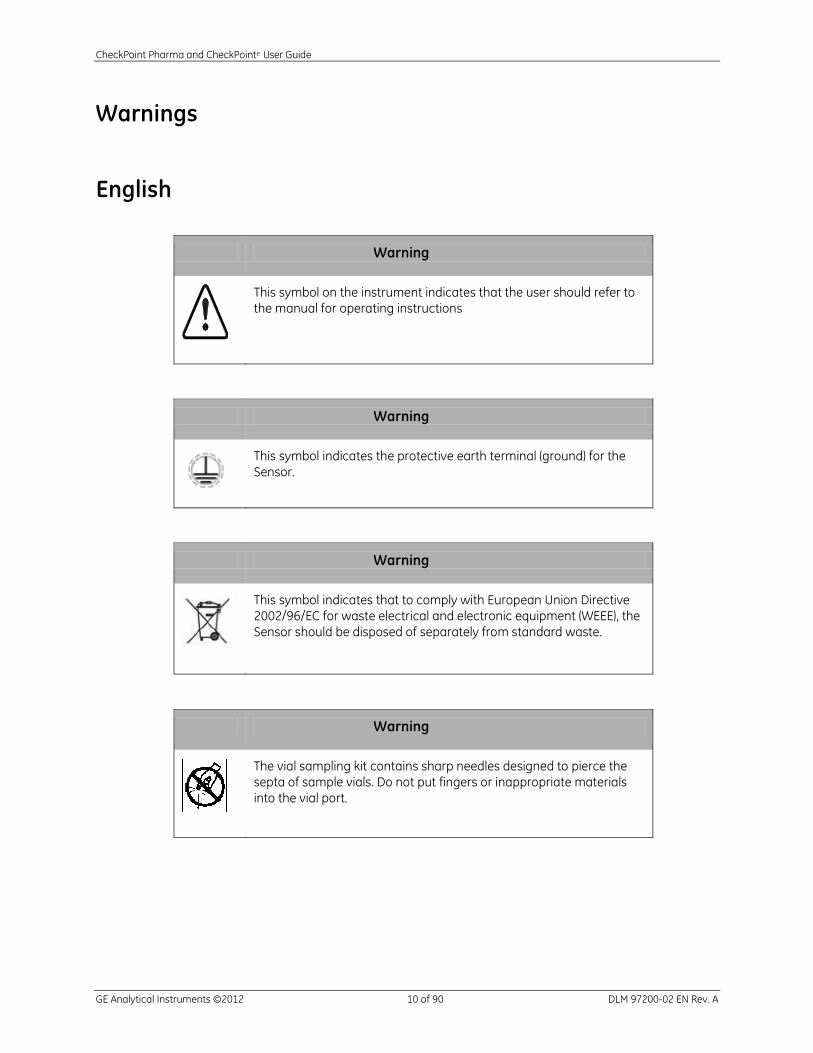
Warning
This symbol on the instrument indicates that the user should refer to
the manual for operating instructions
Warning
This symbol indicates the protective earth terminal (ground) for the
Sensor.
Warning
This symbol indicates that to comply with European Union Directive
2002/96/EC for waste electrical and electronic equipment (WEEE), the
Sensor should be disposed of separately from standard waste.
Warning
The vial sampling kit contains sharp needles designed to pierce the
septa of sample vials. Do not put fingers or inappropriate materials
into the vial port.

CheckPoint Pharma and CheckPointe User Guide
GE Analytical Instruments ©2012 11 of 90 DLM 97200-02 EN Rev. A
Warning
Any operation requiring access to the inside of the Sensor, including installation of
maintenance items, could result in injury. To avoid potentially dangerous shock or
burn, turn off power and, if possible, disconnect from the power supply before
opening the Sensor.
Warning
The UV lamp contains mercury and may be considered hazardous material in your
local area. Dispose of it in accordance with federal, state, or local government
regulations.
Warning
To protect against accidental exposure to ultra-violet radiation, do not operate the
UV lamp outside of its protective housing.
Warning
Before replacing the UV lamp, remove the battery from the Sensor and disable the
external circuit breaker.
Warning
This is a Safety Class I product. It must be must be attached to a grounded power
source.
Warning
If this instrument is used in a manner not specified by GE Analytical Instruments
USA, the protection provided by the instrument may be impaired.

CheckPoint Pharma and CheckPointe User Guide
GE Analytical Instruments ©2012 12 of 90 DLM 97200-02 EN Rev. A
Warning
Always stop analysis and power off the Sensor before unplugging the power cord
or removing the battery.
Warning
This is a Class A product. In a domestic environment, this product may cause
electromagnetic interference in which case the user may be required to take
adequate measures to correct the interference.
Warning
Equipment adjacent to the Sensor may be subject to electromagnetic interference
(EMI).
Warning
To ensure proper Sensor performance, only operate the Sensor in an environment
that complies with the Sensor’s environmental specifications.
Warning
The calibration kit contains a sharp needle. Do not put fingers or inappropriate
materials near the needle.
Warning
Install an external circuit breaker and overcurrent protection if you use power
conduit.
CheckPoint Pharma and CheckPointe User Guide
GE Analytical Instruments ©2012 13 of 90 DLM 97200-02 EN Rev. A
Warning
Before shipping the Sensor, remove the battery and drain all water from the
Sensor.
Warning
To prevent damage to the instrument, do NOT use the CheckPointe with samples
containing ozone.
Warning
If you experience an issue with the printed circuit assembly (PCA) that contains a
lithium battery, please contact GE Analytical instruments for return instructions.
Whenever changing the lithium battery, observe the correct polarity. Dispose of
used batteries according to the manufacturer’s instructions and local disposal
requirements.
CheckPoint Pharma and CheckPointe User Guide
GE Analytical Instruments ©2012 14 of 90 DLM 97200-02 EN Rev. A
This page is intentionally left blank.

CheckPoint Pharma and CheckPointe User Guide
GE Analytical Instruments ©2012 15 of 90 DLM 97200-02 EN Rev. A
Chapter 1 — Introduction
The CheckPoint* Pharma and CheckPointe Portable/On-Line TOC Sensors from GE Analytical
Instruments are high-sensitivity sensors used to measure the concentration of total organic carbon
(TOC) in water. The CheckPoint Pharma uses stainless steel sample inlet tubing, enabling high-
temperature and o-zone compatibility specific to Pharmaceutical industry applications. The CheckPointe
is designed with PEEK sample inlet tubing that produces greater sensitivity pertinent to the
Semiconductor, Power, and other industry applications (that do not require high-temperature or o-zone
compatibility).
The Sensors are based on the oxidation of organic compounds using UV radiation. The instruments
measure the difference in conductivity before and after oxidation of the sample.
The CheckPoint Pharma and CheckPointe Sensors are easy to operate, with extremely low maintenance,
and require no special training or chemical knowledge. The Sensors are calibrated at the factory, and
calibration remains stable for approximately six months. Calibration can be performed easily at
installation sites with the optional CheckPoint Vial Sampling Kit.
This User Guide describes typical operational requirements and recommended procedures that are
valid for most applications, and that apply to both the CheckPoint Pharma and CheckPointe
Portable/On-line TOC Sensors (which, for the remainder of this manual will referenced as CheckPoint
Sensors). Instructions specific to one model or another are noted as such (CheckPoint Pharma or
CheckPointe. as applicable). Special conditions in operating environments may require modifications to
the recommendations in this manual. Contact GEAI Technical Support (U.S. customers) at 800.255.6964
or at 44 (0) 161.864.6800 (UK customers). In other parts of the world, contact your local GEAI
representative.
* Trademark of General Electric Company; may be registered in one or more countries.

CheckPoint Pharma and CheckPointe User Guide
GE Analytical Instruments ©2012 16 of 90 DLM 97200-02 EN Rev. A
This page is intentionally left blank.
CheckPoint Pharma and CheckPointe User Guide
GE Analytical Instruments ©2012 17 of 90 DLM 97200-02 EN Rev. A
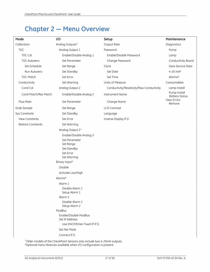
Chapter 2 — Menu Overview
Older models of the CheckPoint Sensors only include two 4-20mA outputs.
*Optional menu features available when I/O configuration is present.
Mode I/O Setup Maintenance
Calibration Analog Outputs* Output Rate Diagnostics
TOC Analog Output 1 Password Pump
TOC Cal Enable/Disable Analog 1 Enable/Disable Password Lamp
TOC Autozero Set Parameter Change Password Conductivity Board
Set Schedule Set Range Clock Save Service Data
Run Autozero Set Standby Set Date 4-20 mA*
TOC Match Set Error Set Time Alarms*
Conductivity Set Warning Units of Measure Consumables
Cond Cal Analog Output 2 Conductivity/Resistivity/Raw Conductivity Lamp Install
Cond Match/Res Match Enable/Disable Analog 2 Instrument Name Pump Install Battery Status
Flow Rate Set Parameter Change Name View Errors Remove
Grab Sample Set Range LCD Contrast
Sys Constants Set Standby Language
View Constants Set Error Inverse Display (F1)
Restore Constants Set Warning
Analog Output 3
Enable/Disable Analog 3
Set Parameter Set Range
Set Standby
Set Error Set Warning
Binary Input*
Disable
Activate Low/High
Alarms*
Alarm 1
Disable Alarm 1 Setup Alarm 1
Alarm 2
Disable Alarm 2 Setup Alarm 2
ModBus
Enable/Disable ModBus Set IP Address
Use DHCP/Enter Fixed IP (F1)
Set Net Mask
Connect (F1)

CheckPoint Pharma and CheckPointe User Guide
GE Analytical Instruments ©2012 18 of 90 DLM 97200-02 EN Rev. A
This page is intentionally left blank.
CheckPoint Pharma and CheckPointe User Guide
GE Analytical Instruments ©2012 19 of 90 DLM 97200-02 EN Rev. A
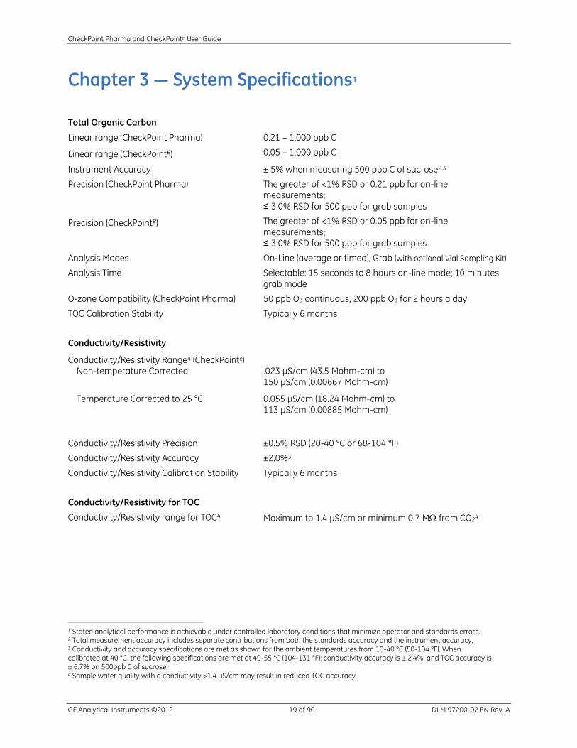
Chapter 3 — System Specifications1
Total Organic Carbon
Linear range (CheckPoint Pharma) 0.21 – 1,000 ppb C
Linear range (CheckPointe) 0.05 – 1,000 ppb C
Instrument Accuracy ± 5% when measuring 500 ppb C of sucrose2,3
Precision (CheckPoint Pharma) The greater of <1% RSD or 0.21 ppb for on-line measurements; ≤ 3.0% RSD for 500 ppb for grab samples
Precision (CheckPointe) The greater of <1% RSD or 0.05 ppb for on-line measurements; ≤ 3.0% RSD for 500 ppb for grab samples
Analysis Modes On-Line (average or timed), Grab (with optional Vial Sampling Kit)
Analysis Time Selectable: 15 seconds to 8 hours on-line mode; 10 minutes grab mode
O-zone Compatibility (CheckPoint Pharma) 50 ppb O3 continuous, 200 ppb O3 for 2 hours a day
TOC Calibration Stability Typically 6 months
Conductivity/Resistivity
Conductivity/Resistivity Range4 (CheckPointe) Non-temperature Corrected:
Temperature Corrected to 25 °C:
.023 μS/cm (43.5 Mohm-cm) to 150 μS/cm (0.00667 Mohm-cm)
0.055 μS/cm (18.24 Mohm-cm) to 113 μS/cm (0.00885 Mohm-cm)
Conductivity/Resistivity Precision ±0.5% RSD (20-40 °C or 68-104 °F)
Conductivity/Resistivity Accuracy
Conductivity/Resistivity Calibration Stability
Conductivity/Resistivity for TOC
Conductivity/Resistivity range for TOC4
±2.0%3
Typically 6 months
Maximum to 1.4 μS/cm or minimum 0.7 M from CO24
1 Stated analytical performance is achievable under controlled laboratory conditions that minimize operator and standards errors. 2 Total measurement accuracy includes separate contributions from both the standards accuracy and the instrument accuracy. 3 Conductivity and accuracy specifications are met as shown for the ambient temperatures from 10-40 °C (50-104 °F). When calibrated at 40 °C, the following specifications are met at 40-55 °C (104-131 °F): conductivity accuracy is ± 2.4%, and TOC accuracy is ± 6.7% on 500ppb C of sucrose. 4 Sample water quality with a conductivity >1.4 μS/cm may result in reduced TOC accuracy.
CheckPoint Pharma and CheckPointe User Guide
GE Analytical Instruments ©2012 20 of 90 DLM 97200-02 EN Rev. A
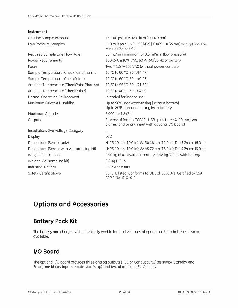
Instrument
On-Line Sample Pressure 15-100 psi (103-690 kPa) (1.0-6.9 bar)
Low Pressure Samples -1.0 to 8 psig (-6.9 – 55 kPa) (-0.069 – 0.55 bar) with optional Low Pressure Sample Kit
Required Sample Line Flow Rate 60 mL/min minimum or 0.5 ml/min (low pressure)
Power Requirements 100-240 ±10% VAC, 60 W, 50/60 Hz or battery
Fuses Two T 1.6 A/250 VAC (without power conduit)
Sample Temperature (CheckPoint Pharma) 10 °C to 90 °C (50-194 °F)
Sample Temperature (CheckPointe) 10 °C to 60 °C (50-140 °F)
Ambient Temperature (CheckPoint Pharma) 10 °C to 55 °C (50-131 °F)3
Ambient Temperature (CheckPointe) 10 °C to 40 °C (50-104 °F)
Normal Operating Environment Intended for indoor use
Maximum Relative Humidity Up to 90%, non-condensing (without battery) Up to 80% non-condensing (with battery)
Maximum Altitude 3,000 m (9,843 ft)
Outputs Ethernet (Modbus TCP/IP), USB, (plus three 4–20 mA, two alarms, and binary input with optional I/O board)
Installation/Overvoltage Category II
Display LCD
Dimensions (Sensor only) H: 25.40 cm (10.0 in); W: 30.48 cm (12.0 in); D: 15.24 cm (6.0 in)
Dimensions (Sensor with vial sampling kit) H: 25.40 cm (10.0 in); W: 45.72 cm (18.0 in); D: 15.24 cm (6.0 in)
Weight (Sensor only) 2.90 kg (6.4 lb) without battery; 3.58 kg (7.9 lb) with battery
Weight (Vial sampling kit) 0.6 kg (1.3 lb)
Industrial Ratings IP 23 enclosure
Safety Certifications CE, ETL listed. Conforms to UL Std. 61010-1. Certified to CSA C22.2 No. 61010-1.
Options and Accessories
Battery Pack Kit
The battery and charger system typically enable four to five hours of operation. Extra batteries also are available.
I/O Board
The optional I/O board provides three analog outputs (TOC or Conductivity/Resistivity, Standby and Error), one binary input (remote start/stop), and two alarms and 24 V supply.

CheckPoint Pharma and CheckPointe User Guide
GE Analytical Instruments ©2012 21 of 90 DLM 97200-02 EN Rev. A
Vial Sampling Kit
The CheckPoint Vial Sampling Kit, which attaches easily to the Sensor, allows users to measure standards and grab samples in vials.
Low-Pressure Sampling Kit
The Low-Pressure Sampling Kit includes Teflon® and stainless steel sampling tubes and a waste bag for collecting zero-pressure samples in the laboratory or fab.
Sample Inlet Filter
The 60 μm sample inlet filter is recommended for on-line sampling.
Figure 1: Sensor Schematic
Printer
For a list of GE recommended printers for the CheckPoint instruments, go to Products link on our Web
site http://www.geinstruments.com. Select TOC Analyzers and Sensors Check Point Sensor
CheckPoint Options and Accessories.

CheckPoint Pharma and CheckPointe User Guide
GE Analytical Instruments ©2012 22 of 90 DLM 97200-02 EN Rev. A
This page is intentionally left blank.
CheckPoint Pharma and CheckPointe User Guide
GE Analytical Instruments ©2012 23 of 90 DLM 97200-02 EN Rev. A
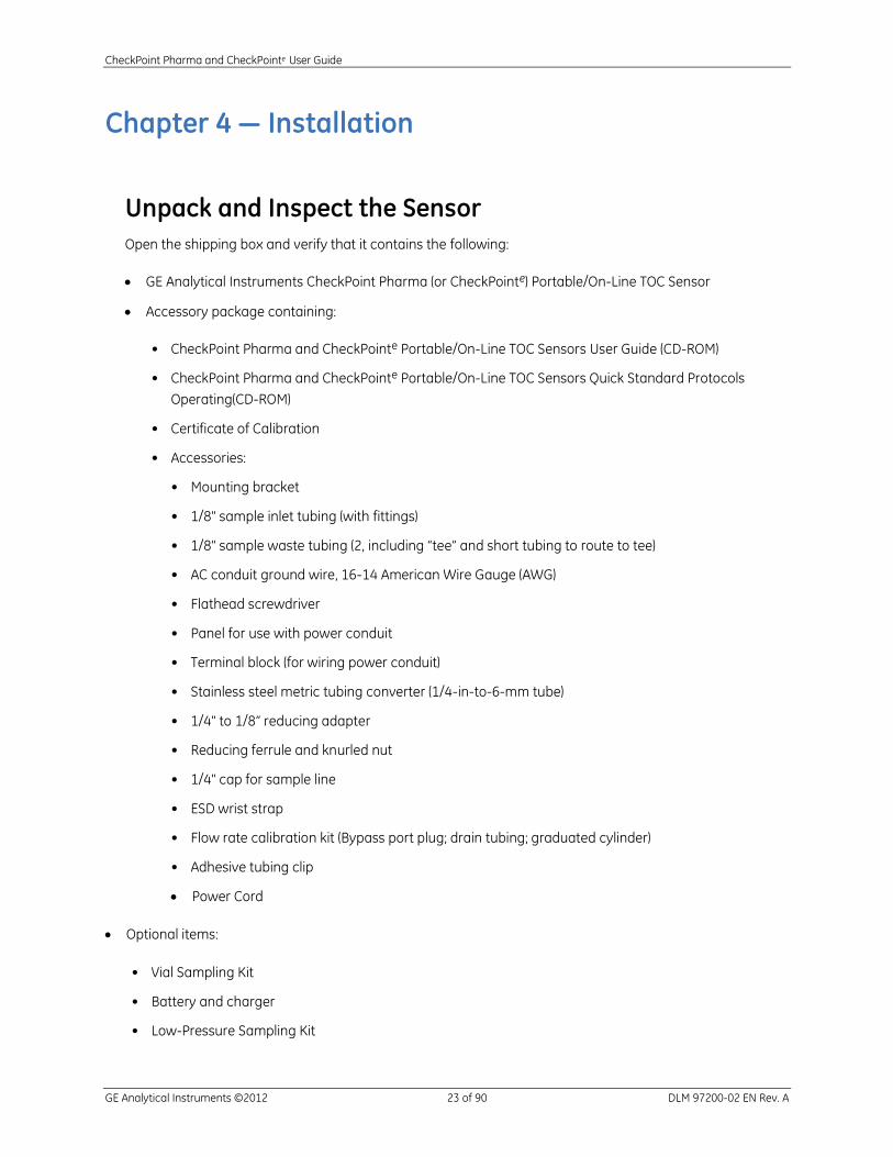
Chapter 4 — Installation
Unpack and Inspect the Sensor
Open the shipping box and verify that it contains the following:
GE Analytical Instruments CheckPoint Pharma (or CheckPointe) Portable/On-Line TOC Sensor
Accessory package containing:
• CheckPoint Pharma and CheckPointe Portable/On-Line TOC Sensors User Guide (CD-ROM)
• CheckPoint Pharma and CheckPointe Portable/On-Line TOC Sensors Quick Standard Protocols
Operating(CD-ROM)
• Certificate of Calibration
• Accessories:
• Mounting bracket
• 1/8" sample inlet tubing (with fittings)
• 1/8" sample waste tubing (2, including “tee” and short tubing to route to tee)
• AC conduit ground wire, 16-14 American Wire Gauge (AWG)
• Flathead screwdriver
• Panel for use with power conduit
• Terminal block (for wiring power conduit)
• Stainless steel metric tubing converter (1/4-in-to-6-mm tube)
• 1/4" to 1/8” reducing adapter
• Reducing ferrule and knurled nut
• 1/4" cap for sample line
• ESD wrist strap
• Flow rate calibration kit (Bypass port plug; drain tubing; graduated cylinder)
• Adhesive tubing clip
Power Cord
Optional items:
• Vial Sampling Kit
• Battery and charger
• Low-Pressure Sampling Kit

CheckPoint Pharma and CheckPointe User Guide
GE Analytical Instruments ©2012 24 of 90 DLM 97200-02 EN Rev. A
Optional Installation Equipment
The following equipment also may be required, depending on your installation configuration:
• Insulated wire, 22-12 AWG, rated to 300 Volts for analog and alarm outputs
• Analog (4-20 mA) recorder
• Insulated wire (18-12 AWG, rated to 300 Volts) for AC power conduit
• An external circuit breaker or switch that disconnects both poles of the supply voltage, rated
appropriately, if using power conduit.
• PLC or SCADA system for use with Modbus
• 60 micron filter for sample inlet line
• USB printer (For a list of GE recommended printers for the CheckPoint instruments, go to the
Products link on our Web site http://www.geinstruments.com. Select TOC Analyzers and Sensors
Check Point Sensor Options and Accessories.)
Step 1: Install the Mounting Bracket (Optional)
If you will be installing the Sensor in a fixed (permanent) position, install the provided mounting bracket in
the desired location by fastening screws through the bracket slots. Refer to Figure 47: Mounting Bracket
Dimensions on page 84 for bracket dimensions. After the bracket has been mounted, attach the Sensor to
the bracket by placing the mounting posts in the wider portion of the bracket cutouts and then pressing
down firmly but gently.
NOTE: If you plan to install the Vial sampling kit during maintenance activities with the Sensor wall mounted,
allow at least 30.5 cm (12 in) on the right side of the Sensor for attaching the kit (see Figure 45 on page 82).
Avoid direct sunlight and extreme temperatures; operating at elevated temperatures (greater than 40 °C)
prevents proper operation, and operating at low temperatures (10 °C) can cause errors in measurements.
Also make sure there is at least 1.2 in of clearance between the wall and the back of the Sensor.
If you will not be mounting the CheckPoint, attach the optional adhesive tubing clip to the back of the
Sensor, so you can restrain coiled sample cable while the Sensor is in transit.
CheckPoint Pharma and CheckPointe User Guide
GE Analytical Instruments ©2012 25 of 90 DLM 97200-02 EN Rev. A
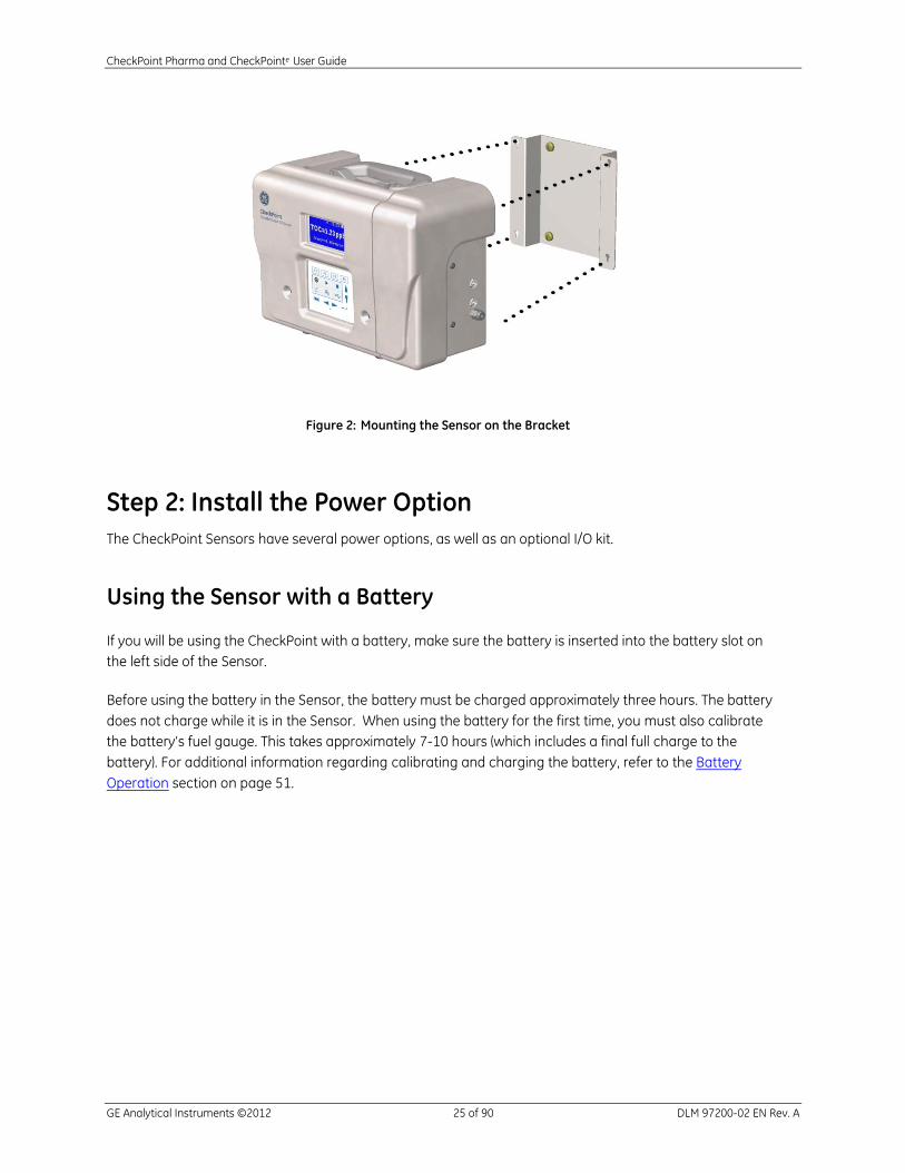
Figure 2: Mounting the Sensor on the Bracket
Step 2: Install the Power Option
The CheckPoint Sensors have several power options, as well as an optional I/O kit.
Using the Sensor with a Battery
If you will be using the CheckPoint with a battery, make sure the battery is inserted into the battery slot on
the left side of the Sensor.
Before using the battery in the Sensor, the battery must be charged approximately three hours. The battery
does not charge while it is in the Sensor. When using the battery for the first time, you must also calibrate
the battery’s fuel gauge. This takes approximately 7-10 hours (which includes a final full charge to the
battery). For additional information regarding calibrating and charging the battery, refer to the Battery
Operation section on page 51.
CheckPoint Pharma and CheckPointe User Guide
GE Analytical Instruments ©2012 26 of 90 DLM 97200-02 EN Rev. A
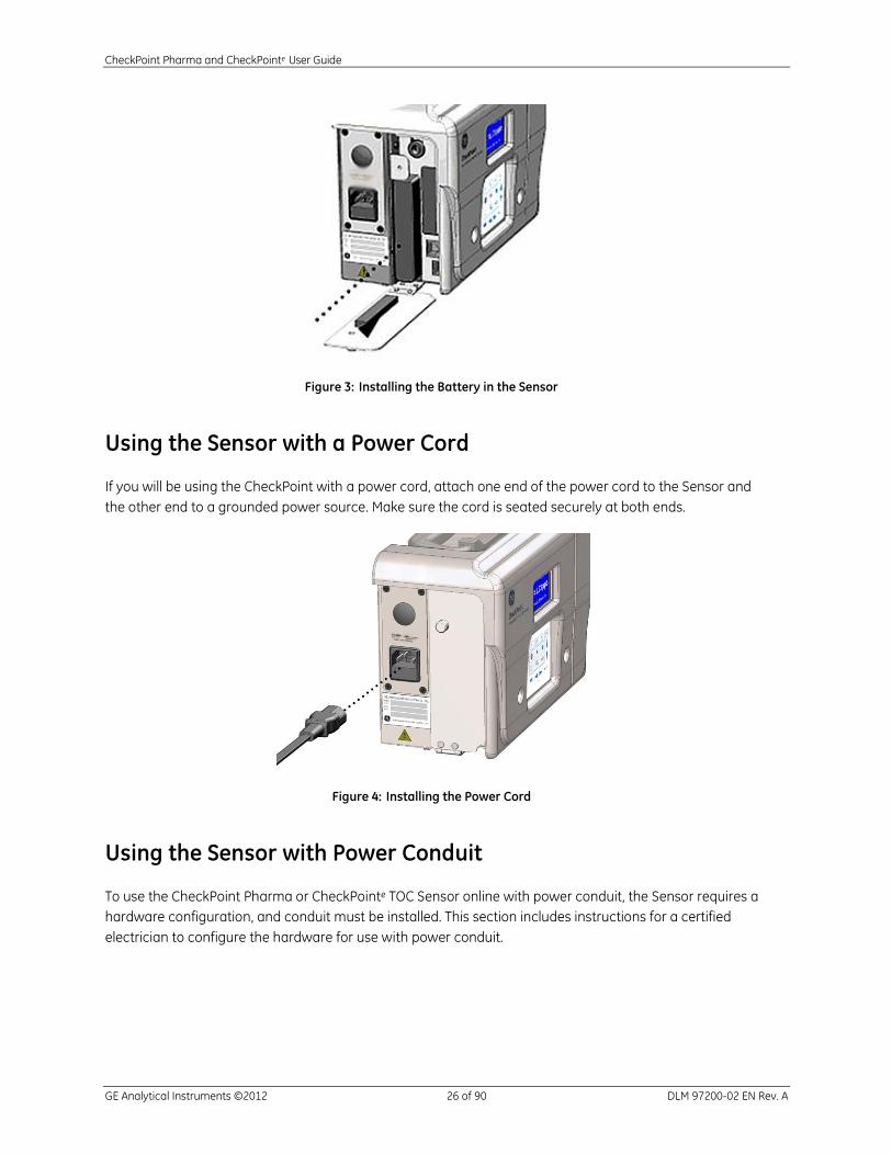
Figure 3: Installing the Battery in the Sensor
Using the Sensor with a Power Cord
If you will be using the CheckPoint with a power cord, attach one end of the power cord to the Sensor and
the other end to a grounded power source. Make sure the cord is seated securely at both ends.
Figure 4: Installing the Power Cord
Using the Sensor with Power Conduit
To use the CheckPoint Pharma or CheckPointe TOC Sensor online with power conduit, the Sensor requires a
hardware configuration, and conduit must be installed. This section includes instructions for a certified
electrician to configure the hardware for use with power conduit.
CheckPoint Pharma and CheckPointe User Guide
GE Analytical Instruments ©2012 27 of 90 DLM 97200-02 EN Rev. A
Warning
This procedure should ONLY be performed by a certified electrician. The following
step-by-step instructions are intended to be provided to the electrician as a
guideline for converting the CheckPoint for use with power conduit, and to provide
CheckPoint with conduit-specific electrical requirements.
Install an external circuit breaker and overcurrent protection if you use power
conduit.
1. If the power cord is attached, remove it.
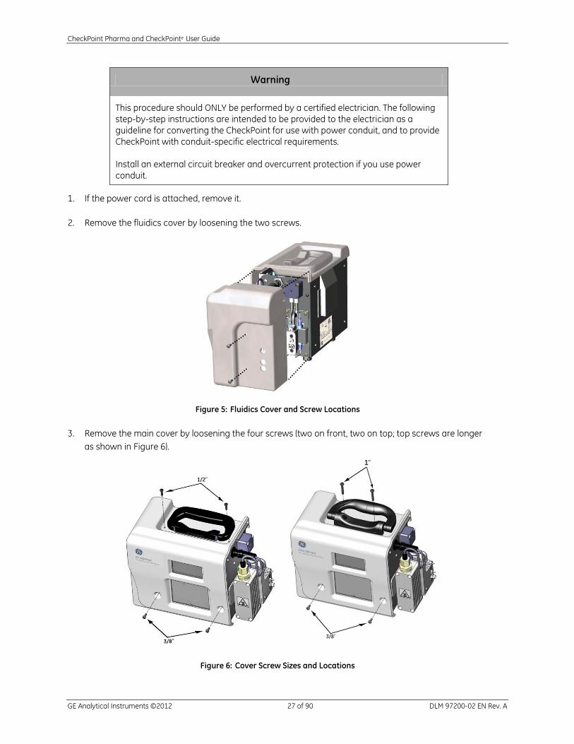
2. Remove the fluidics cover by loosening the two screws.
Figure 5: Fluidics Cover and Screw Locations
3. Remove the main cover by loosening the four screws (two on front, two on top; top screws are longer
as shown in Figure 6).
Figure 6: Cover Screw Sizes and Locations

CheckPoint Pharma and CheckPointe User Guide
GE Analytical Instruments ©2012 28 of 90 DLM 97200-02 EN Rev. A
4. Wearing an ESD strap (one is provided in the Accessories Kit), disconnect the three wires in the power
entry module from the Sensor:
• Pull the two connectors out from the left side of the fuse holder.
• Using a 3/8 in. nut driver, loosen the nut to remove the ground wire.
5. Loosen the four screws on the power module panel and remove the panel from the Sensor
(see Figure 7).
Figure 7: The Default Power Module Panel and I/O Cover
6. Attach the new power module panel to the Sensor by securing the screws. Make sure the panel is
correctly positioned. The labels should be right-side up so that they are readable.
In the pass-through port, use a watertight sealing device (or strain relief hub) that is appropriate for
your environment.
7. Remove the covers from the two fuse holders and then remove the two fuses (see Figure 8).
8. Remove the fuse holders by loosening the two screws and pulling the fuse holders out of the Sensor.
9. Cut the tab connectors off the wires that connect to the right side of the fuse holders (see Figure 8).
Power Module Panel
CheckPoint Pharma and CheckPointe User Guide
GE Analytical Instruments ©2012 29 of 90 DLM 97200-02 EN Rev. A
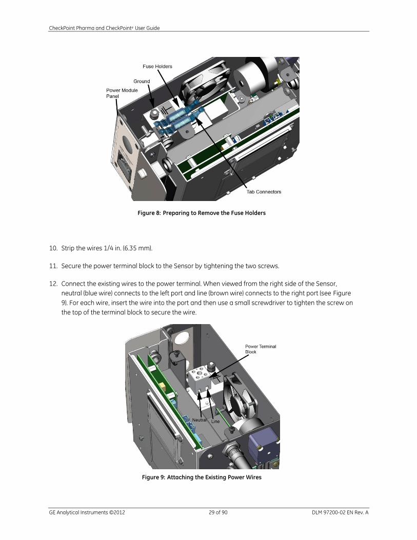
Figure 8: Preparing to Remove the Fuse Holders
10. Strip the wires 1/4 in. (6.35 mm).
11. Secure the power terminal block to the Sensor by tightening the two screws.
12. Connect the existing wires to the power terminal. When viewed from the right side of the Sensor,
neutral (blue wire) connects to the left port and line (brown wire) connects to the right port (see Figure
9). For each wire, insert the wire into the port and then use a small screwdriver to tighten the screw on
the top of the terminal block to secure the wire.
Figure 9: Attaching the Existing Power Wires

CheckPoint Pharma and CheckPointe User Guide
GE Analytical Instruments ©2012 30 of 90 DLM 97200-02 EN Rev. A
13. Route the power wiring into the Sensor through the pass-through port in the power module panel.
You can also choose to install a strain relief hub at the pass-through port.
NOTE: Wire should be 18-12 AWG, rated to 300 Volts. The strip length should be 8 mm (.33 in).
14. Connect the power wires to the terminal block, with the line (brown or black wire) connected to the
port on the left and neutral (blue or white wire) connected to the port on the right (see Figure 10). For
each wire, insert the wire into the port and then use a small screwdriver to tighten the screw on the
top of the terminal block to secure the wire.
Figure 10: Connecting the Power Wiring (With Conduit)
15. Connect the ground wires to the ground stud; the wire from the power inlet should be on the bottom
(see Figure 11).
A connector for 16-14 AWG wire is provided in the CheckPoint Accessories Kit. If you use wire of a
different gauge, you must provide an appropriate connector.
CheckPoint Pharma and CheckPointe User Guide
GE Analytical Instruments ©2012 31 of 90 DLM 97200-02 EN Rev. A
Figure 11: Stacking Order for the Ground Wires
16. If you also are using conduit for I/O cabling, do not replace the Sensor’s covers. Proceed to the next
step.
If you are installing I/O cabling but are not using I/O conduit, replace the Sensor’s covers and proceed
to the next step.
If you are not using the optional I/O kit, proceed to Step 4: Install the Sample Inlet and Waste Outlet.
Step 3: Install the I/O cabling (Optional)
The Sensor offers a USB port for data download via a USB Flash memory drive and an Ethernet port for
data acquisition. The USB port is located behind the I/O Cover. In addition, you can optionally configure the
Sensor with three 4-20 mA outputs, two alarms, and one binary input.
If you will not be using conduit for I/O wiring, follow these steps:
1. Open the I/O cover by loosening the thumbscrew.
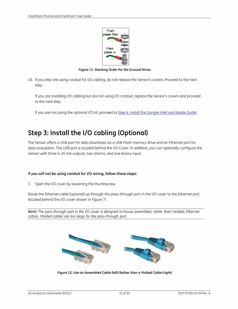
Route the Ethernet cable (optional) up through the pass-through port in the I/O cover to the Ethernet port
(located behind the I/O cover shown in Figure 7).
NOTE: The pass-through port in the I/O cover is designed to house assembled, rather than molded, Ethernet
cables. Molded cables are too large for the pass-through port.
Figure 12: Use an Assembled Cable (left) Rather than a Molded Cable (right)

CheckPoint Pharma and CheckPointe User Guide
GE Analytical Instruments ©2012 32 of 90 DLM 97200-02 EN Rev. A
2. Route the analog out, alarm, and binary input cables up through the pass-through port to the
appropriate terminal connectors. Refer to the tables below for pin functionality on the terminal blocks.
3. Close the I/O cover and tighten the thumbscrew.
4. Replace the main cover and secure the four screws.
5. Replace the fluidics cover and secure the two screws.
If you will be using conduit for I/O wiring, follow these steps:
1. If you have not already done so, remove the fluidics cover by loosening the two screws and the main
cover by loosening the four screws.
2. Open the I/O cover by loosening the thumbscrews.
3. Route the I/O cables into the Sensor through the power module panel pass-through port (see Figure
14).
4. Route the cables through the first grommet and then through the second grommet, to the I/O terminal
blocks (see Figure 13). If needed, you can cut a notch in the grommets to make wire manipulation
easier.
Figure 13: Routing the I/O Cables

CheckPoint Pharma and CheckPointe User Guide
GE Analytical Instruments ©2012 33 of 90 DLM 97200-02 EN Rev. A
Figure 14: Routing the I/O Cables (Detail)
5. For 4-20 mA, binary input, and alarm wiring, connect the wiring to the appropriate pins. Consult the
tables below for pin functionality on each terminal block.
Wire should be 22-12 AWG, rated to 300 Volts. Strip length should be 8-9 mm (.33 in). To attach the
output connections, first remove the terminal block from the I/O board by firmly grasping the terminal
block and pulling it straight out from the board. (Write down the orientation of the terminal block
before removing.)
Completely loosen the screw for each pin you are connecting, insert the wire, tighten the screw, and
then gently pull on each connection to make sure the connection is secure. Then, replace the terminal
blocks. Power isolation level is 240 VAC rms for all terminal blocks. The maximum load for the alarm
ports is 30 VDC at 1.0 A. The maximum 4-20 mA load is 600 ohms.
6. Replace the main cover and secure the four screws.
7. Replace the fluidics cover and secure the two screws.
Table 1: 4-20 mA Outputs (TB1)
Pin Number Output
1 Return 1 (-)
2 4-20 mA 1 (+)
3 Return 2 (-)
4 4-20 mA 2 (+)
5 Return 3 (-)
6 4-20 mA 3 (+)
CheckPoint Pharma and CheckPointe User Guide
GE Analytical Instruments ©2012 34 of 90 DLM 97200-02 EN Rev. A
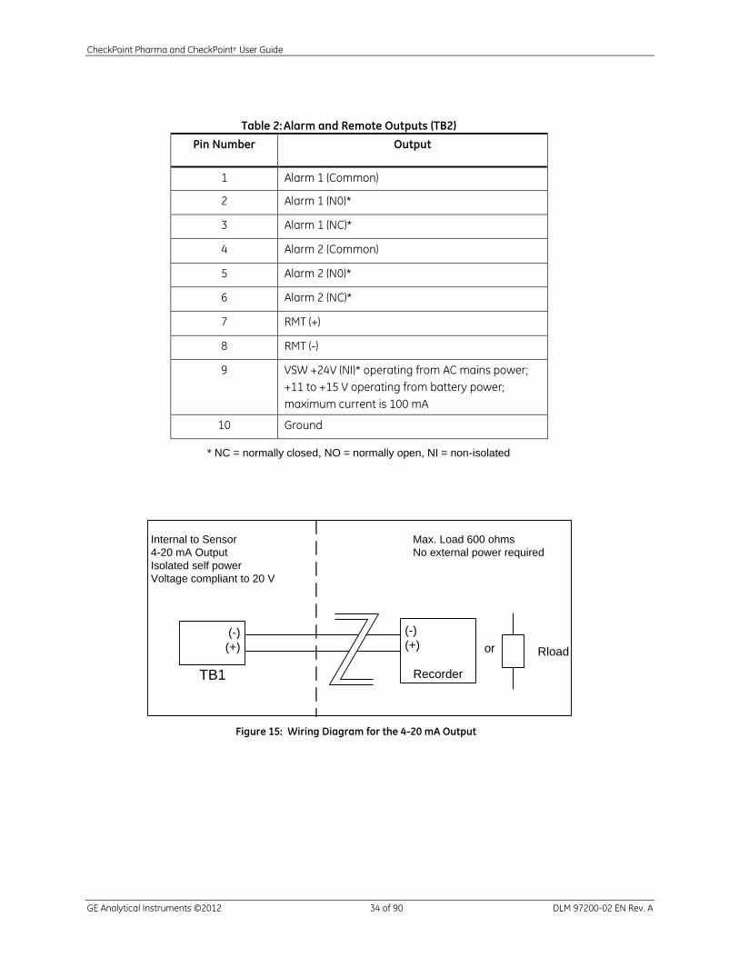
Table 2: Alarm and Remote Outputs (TB2)
Pin Number Output
1 Alarm 1 (Common)
2 Alarm 1 (N0)*
3 Alarm 1 (NC)*
4 Alarm 2 (Common)
5 Alarm 2 (N0)*
6 Alarm 2 (NC)*
7 RMT (+)
8 RMT (-)
9 VSW +24V (NI)* operating from AC mains power;
+11 to +15 V operating from battery power;
maximum current is 100 mA
10 Ground
* NC = normally closed, NO = normally open, NI = non-isolated
(-)
(+)
TB1
Internal to Sensor
4-20 mA Output
Isolated self power
Voltage compliant to 20 V
Max. Load 600 ohms
No external power required
(-)
(+)
Recorder
or Rload
Figure 15: Wiring Diagram for the 4-20 mA Output
CheckPoint Pharma and CheckPointe User Guide
GE Analytical Instruments ©2012 35 of 90 DLM 97200-02 EN Rev. A
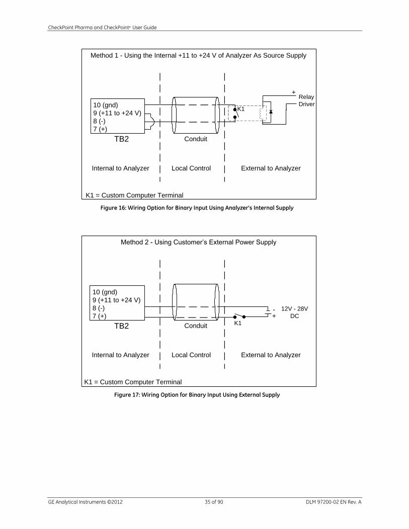
10 (gnd)
9 (+11 to +24 V)
8 (-)
7 (+)
TB2
Internal to Analyzer
Relay
Driver
Local Control External to Analyzer
K1
+
Method 1 - Using the Internal +11 to +24 V of Analyzer As Source Supply
Conduit
K1 = Custom Computer Terminal
Figure 16: Wiring Option for Binary Input Using Analyzer’s Internal Supply
10 (gnd)
9 (+11 to +24 V)
8 (-)
7 (+)
TB2
Internal to Analyzer Local Control External to Analyzer
K1
Method 2 - Using Customer’s External Power Supply
Conduit
-+
K1 = Custom Computer Terminal
12V - 28V
DC
Figure 17: Wiring Option for Binary Input Using External Supply
CheckPoint Pharma and CheckPointe User Guide
GE Analytical Instruments ©2012 36 of 90 DLM 97200-02 EN Rev. A
Step 4: Install the Sample Inlet and Waste Outlet
The Sensor is normally used in On-line mode to measure a flowing sample stream. The flow from the water
source should be disabled until the sample inlet tubing is completely installed and the Sensor is ready to
begin analysis. To ensure against introducing particulates into the Sensor, install the optional in-line filter
on the sample inlet, as well.
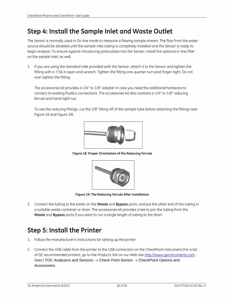
1. If you are using the standard inlet provided with the Sensor, attach it to the Sensor and tighten the
fitting with a 7/16 in open-end wrench. Tighten the fitting one-quarter turn past finger-tight. Do not
over tighten the fitting.
The accessories kit provides a 1/4" to 1/8" adapter in case you need the additional hardware to
connect to existing fluidics connections. The accessories kit also contains a 1/4" to 1/8" reducing
ferrule and hand-tight nut.
To use the reducing fittings, cut the 1/8" fitting off of the sample tube before attaching the fittings (see
Figure 18 and Figure 19).
Figure 18: Proper Orientation of the Reducing Ferrule
Figure 19: The Reducing Ferrule After Installation
2. Connect the tubing to the barbs on the Waste and Bypass ports, and put the other end of the tubing in
a suitable waste container or drain. The accessories kit provides a tee to join the tubing from the
Waste and Bypass ports if you want to run a single length of tubing to the drain.
Step 5: Install the Printer
1. Follow the manufacturer’s instructions for setting up the printer.
2. Connect the USB cable from the printer to the USB connection on the CheckPoint instrument (For a list
of GE recommended printers, go to the Products link on our Web site http://www.geinstruments.com.
Select TOC Analyzers and Sensors Check Point Sensor CheckPoint Options and
Accessories.

CheckPoint Pharma and CheckPointe User Guide
GE Analytical Instruments ©2012 37 of 90 DLM 97200-02 EN Rev. A
Chapter 5 — Basic Operation and Menu Options
The buttons on the CheckPoint touch screen provide easy access to all Sensor functions.
Figure 20: Touch Screen Buttons
Function Keys The four function keys at the top of the touch screen (see Figure 21) are context sensitive; depending on which screen is displayed, the function keys provide quick access to various features. The display will always list the function of each key for that particular screen.
Figure 21: The Function Keys
Main Buttons
Press and hold the power button to power on the Sensor. You can stop pressing the button after the display illuminates. To power off the Sensor, press and hold the button until the Sensor indicates that it is saving settings.
The Start Analysis button starts analysis.
The Stop Analysis button stops analysis.
The Display button cycles through the display mode options. (TOC, TOC Countdown, TOC and Conductivity or TOC and Resistivity, TOC Chart, View Data, and System Information). When the Sensor is in standby, only the View Data, TOC Chart, and System Information screens are available.
The Menu button displays the main menu screen. Menus provide access to configuration screens and advanced functions of the Sensor.
The Save button starts a download of all of the data and system constants
on the Sensor to the USB storage device.

CheckPoint Pharma and CheckPointe User Guide
GE Analytical Instruments ©2012 38 of 90 DLM 97200-02 EN Rev. A
Standby Mode
When the Sensor is not in performing on-line, it can be placed in Standby mode by pressing the Stop
button and then pressing F1. When the Sensor is in standby mode and running on AC power, the sample
pump stops running and the UV lamp remains on. When the Sensor is in standby mode and running on
battery power, the sample pump stops running and the UV lamp turns off.
Navigation Keys The Horizontal Scroll Bar scrolls left and right, and the Vertical Scroll Bar scrolls up and down.
The scroll bars have three modes of operation, which are activated depending on how you press the buttons:
Stroke mode lets you move rapidly by stroking the scroll bar (move your finger or stylus from one end of the scroll bar to the other) in the direction you want to scroll.
Auto-repeat mode lets you press and hold the arrow that corresponds to the direction you want
to scroll. Scrolling will accelerate as you hold the button down.
Tap mode lets you tap one of the two arrows to scroll one line in the direction indicated by the arrow.
Figure 22: The Horizontal and Vertical Scroll Bars
The Backspace key deletes the character to the left of the cursor.
Figure 23: Backspace Key
The Enter key is used to select an item or value from a group.
Figure 24: The Enter Key
CheckPoint Pharma and CheckPointe User Guide
GE Analytical Instruments ©2012 39 of 90 DLM 97200-02 EN Rev. A
Starting and Stopping Analysis
To start analysis, press the button. When the Sensor is in On-Line Mode, a flashing triangle displays
in the upper right corner of the screen. A confirmation screen is displayed before starting analysis. Press
the button followed by F1 to stop analysis.
If a printer has been installed, the CheckPoint will print the results of each measurement.
To start the Sensor in Grab mode, refer to the Grab Sample Mode section on page 39..
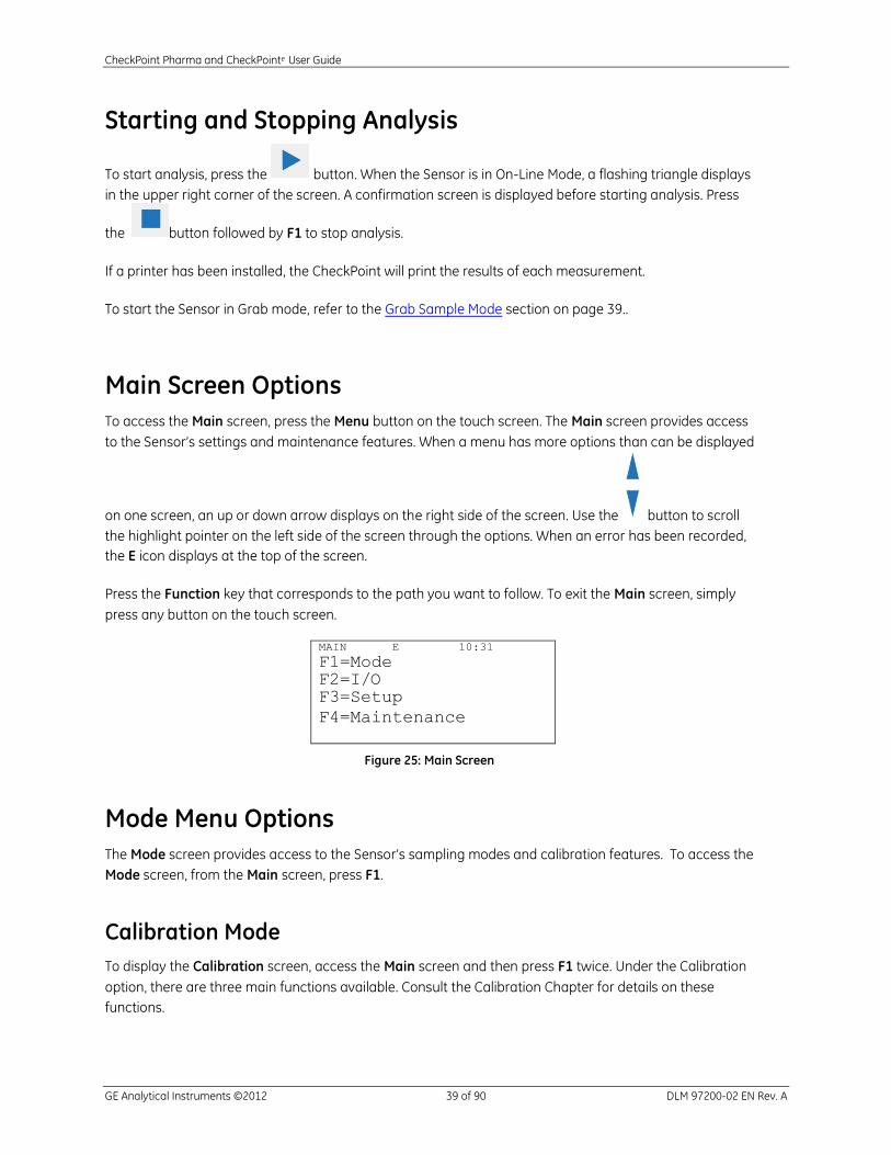
Main Screen Options
To access the Main screen, press the Menu button on the touch screen. The Main screen provides access
to the Sensor’s settings and maintenance features. When a menu has more options than can be displayed
on one screen, an up or down arrow displays on the right side of the screen. Use the button to scroll
the highlight pointer on the left side of the screen through the options. When an error has been recorded,
the E icon displays at the top of the screen.
Press the Function key that corresponds to the path you want to follow. To exit the Main screen, simply
press any button on the touch screen.
MAIN E 10:31
F1=Mode F2=I/O F3=Setup
F4=Maintenance
Figure 25: Main Screen
Mode Menu Options
The Mode screen provides access to the Sensor’s sampling modes and calibration features. To access the
Mode screen, from the Main screen, press F1.
Calibration Mode
To display the Calibration screen, access the Main screen and then press F1 twice. Under the Calibration
option, there are three main functions available. Consult the Calibration Chapter for details on these
functions.
CheckPoint Pharma and CheckPointe User Guide
GE Analytical Instruments ©2012 40 of 90 DLM 97200-02 EN Rev. A
Grab Sample Mode
You can run the Analyzer in Grab Sample mode when you need to analyze sample in a bottle (or, if you
have purchased the optional Calibration kit, in a vial). To enter Grab Sample mode, access the Main screen,
press F1, and then press F2. Make sure the sample inlet line is configured to draw sample from a vial or
bottle before pressing F1 to start analysis. If needed, press F4 to stop analysis.
If a printer has been installed, the CheckPoint will print the results of the grab measurement upon
completion.
System Constants
From the Mode screen, select View Constants to view the current Sensor constants; select Restore
Constants to load constants into the Sensor from a file saved to a USB flash memory drive. You can also
import the system constants information into a spreadsheet program for reference, as described in
”Appendix B: Importing Sensor Data into a Spreadsheet Program.”
I/O Menu Options
When configured with the I/O option, the CheckPoint provides a variety of data output options. Access the
I/O menu by pressing F2 from the Main screen.
Analog Outputs
The CheckPoint provides three analog outputs, which can be configured as follows.
NOTE: This menu option does not appear if the additional I/O features are not installed in your configuration.
Instruments built prior to release 1.04 may have only two analog outputs. The available outputs otherwise
operate the same.
1. Scroll to Analog Outputs and press .
2. Press F1 to configure Analog output 1, press F2 to configure Analog output 2, or press F3 to
configure Analog output 3. (These menu options are not displayed if the Sensor has not been
configured with I/O features.)
3. Pressing the Function button enters the selected channel’s Setup screen. Use the Vertical Scroll
bar to highlight an option, and then press the button to select that option.
CheckPoint Pharma and CheckPointe User Guide
GE Analytical Instruments ©2012 41 of 90 DLM 97200-02 EN Rev. A
4. Make sure the analog output is enabled by highlighting Analog Output to toggle the analog
output state between On and Off.
5. Select Set Parameter (TOC, Conductivity/Resistivity, Temperature).
Press F1 to select TOC, press F2 to select conductivity or resistivity, or press F3 to select
temperature as the analog output parameter. (You can specify whether data should be
reported as conductivity or resistivity via the Setup menu, Units of Measure. Conductivity
will be either temperature corrected or raw conductivity as specified in the Setup menu.)
The Analog Min screen displays, indicating the most recent minimum value for the
selected parameter. To change the value, use the Horizontal Scroll bar to select the field,
and use the Vertical Scroll bar to change the value in the selected field. Press F1 to apply
the new value.
The Analog Max screen displays, indicating the most recent maximum value for the
selected parameter. To change the value, use the Horizontal Scroll bar to select the field,
and use the Vertical Scroll bar to change the value in the selected field. Press F1 to apply
the new value.
6. Analog MIN/MAX is also available without reselecting Set Parameter.
7. The Sensor allows you to set the output level when the Sensor switches into Standby mode, when
an error is detected, or when a warning is detected. Select Standby to set the Standby output.
Select Error to set the error output. Select Warning to set the Warning output.
Use the Vertical Scroll bar to highlight a value, and then press the Enter key to select that
value.
The available values are 0.0 mA, 2.5 mA, 4.0 mA, 20 mA, and Hold. The first four options
set the standby or error value to the specified value. The Hold option sets the standby or
error value to retain the last value output by the Sensor.
Make sure you have set different values for Standby, Error, and Warning.
Binary Input
The CheckPoint can be configured with one remote start binary input, as follows:
The Binary Input screen shows the current state of the binary input.
1. Scroll to Binary Input and press .
2. Press F1 to toggle the binary input state between Enabled and Disabled. Set the value to Enabled
to enable remote start to begin the analysis.

CheckPoint Pharma and CheckPointe User Guide
GE Analytical Instruments ©2012 42 of 90 DLM 97200-02 EN Rev. A
3. Press F2 to toggle the binary input active state between High and Low.
With Binary Input not connected and state = Enable, if active state is set to High, the
Sensor will begin taking readings and not remain stopped when you press the
button. Under the described conditions, if active state is set to Low, the Sensor will not
begin taking readings when you press the button.
Alarms
The Sensor can be configured with two alarm outputs, as follows:
1. Scroll to Alarms and press the button.
2. Press F1 to configure Alarm 1 or press F2 to configure Alarm 2.
3. Press F1 to toggle the alarm between Enabled and Disabled.
4. Press F2 to set up the alarm.
5. Use the Vertical Scroll bar to highlight a value, and then press the Enter key to select that value.
Available values are:
TOC: the alarm activates when the TOC value exceeds the specified limit.
Conductivity or Resistivity: depending on which unit of measure has been selected, you
can set the alarm to activate when the conductivity value exceeds a specified limit or
when the resistivity value falls below a specified limit.
TOC trend: the alarm activates when the TOC trend exceeds a specified limit.
Error: the alarm activates when an error has been reported.
Standby: the alarm activates when the Sensor is in standby mode.
Warning: the alarm activates when a warning has been reported.
Error or Warning: the alarm activates when either an error or warning has been
reported.
6. If you set the alarm to activate on TOC, Conductivity/Resistivity, or TOC Trend, the Alarm Limit
screen displays. Use the scroll bars to enter the value.
CheckPoint Pharma and CheckPointe User Guide
GE Analytical Instruments ©2012 43 of 90 DLM 97200-02 EN Rev. A
Using the Ethernet Connection and Modbus
To export data using the Ethernet port, the Sensor exports data using the Modbus communication
protocol. Before data can be exported via Ethernet, you must enable Modbus and configure the Sensor’s IP
address. The connection can be made using DHCP or a static IP address.
NOTE: You may need assistance from your network administrator or information technology (IT) department
to set the IP address correctly for your network.
1. Make sure the Ethernet cable is connected to the Sensor. If you will be connecting The CheckPoint to
your network or another computer, attach the other end of the Ethernet cable to an Ethernet port on
your network or the computer.
2. From the Main screen, press the button and then press F2 to select I/O.
3. Use the button to scroll down to select Modbus, and then press the button.
4. Press the button to enable Modbus.
5. Use the button to scroll down to select Set IP Address and then press the button.
6. By default the CheckPoint uses DHCP to request an IP address from the server on your network. If you
will be using DHCP, press F2 to apply the setting. If you will be using a fixed IP address, press F1 and
then use the keypad to enter the IP address.
7. Use the button to scroll down to select Set Net Mask and then press the button.
8. Use the keypad to enter the net mask, and then press F1.
9. Press F1 to connect. If the Sensor does not connect, try cycling the power to the Sensor and connect
again.
Pressing F4 cancels any changes to the IP address and returns to the Modbus screen. Use the Vertical
Scroll buttons to move between fields, and press the Enter key to enter a new value.

CheckPoint Pharma and CheckPointe User Guide
GE Analytical Instruments ©2012 44 of 90 DLM 97200-02 EN Rev. A
Modbus Register Table
The reference addresses in the table below are the values sent over the Ethernet connection.
Function Code 0x02 Discrete Inputs (read only)
Status 1000 5 bits New Data (0) // bit 0 Error (1) // bit 1 Standby (2) // bit 2 Alarm1 (3) // bit 3 Alarm2 (4) // bit 4
Coils (read) 0x01 State 2000 2 bits Run (0) // bit 0 Stop (1) // bit 1 Coils (write) 0x05
Run 2000 Stop 2001
Input Registers (read only) 0x04
Instrument Family 3010 // 16-bit unsigned Instrument Model 3011 // 16-bit unsigned Serial Number 3012 // 16-bit unsigned Reading Time – Year 3100 // 16-bit unsigned Reading Time – Month 3101 // 16-bit unsigned Reading Time – Day 3102 // 16-bit unsigned Reading Time – Hour 3103 // 16-bit unsigned Reading Time – Minute 3104 // 16-bit unsigned Reading Time – Second 3105 // 16-bit unsigned Error Type 3200 // 16-bit unsigned Error Time – Year 3201 // 16-bit unsigned Error Time – Month 3202 // 16-bit unsigned Error Time – Day 3203 // 16-bit unsigned Error Time – Hour 3204 // 16-bit unsigned Error Time – Minute 3205 // 16-bit unsigned Error Time – Second 3206 // 16-bit unsigned TOC Value IEEE 32-bit float TOC Value Low Word 3300 // 16-bit unsigned TOC Value High Word 3301 // 16-bit unsigned TOC Units 3302 // 16-bit unsigned 1 = ppt 2 = ppb 3 = ppm TOC Trend Value IEEE 32-bit float TOC Trend Value Low Word 3400 // 16-bit unsigned TOC Trend Value High Word 3401 // 16-bit unsigned TOC Trend Units 3402 // 16-bit unsigned 1 = ppt/hr 2 = ppb/hr 3 = ppm/hr
CheckPoint Pharma and CheckPointe User Guide
GE Analytical Instruments ©2012 45 of 90 DLM 97200-02 EN Rev. A
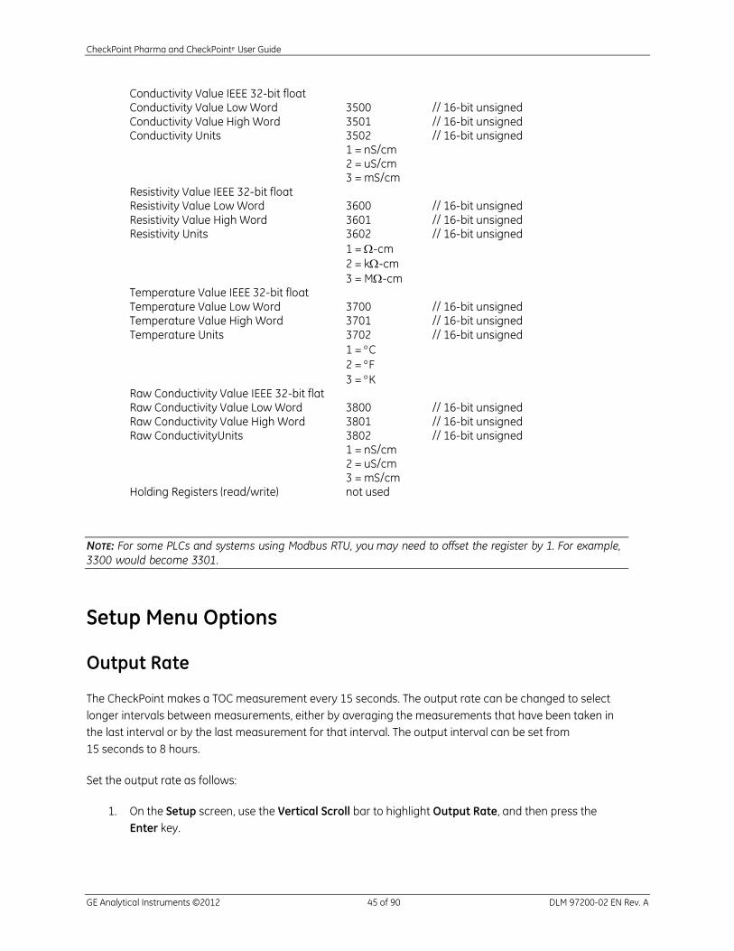
Conductivity Value IEEE 32-bit float Conductivity Value Low Word 3500 // 16-bit unsigned Conductivity Value High Word 3501 // 16-bit unsigned Conductivity Units 3502 // 16-bit unsigned 1 = nS/cm 2 = uS/cm 3 = mS/cm Resistivity Value IEEE 32-bit float Resistivity Value Low Word 3600 // 16-bit unsigned Resistivity Value High Word 3601 // 16-bit unsigned Resistivity Units 3602 // 16-bit unsigned
1 = -cm
2 = k-cm
3 = M-cm Temperature Value IEEE 32-bit float Temperature Value Low Word 3700 // 16-bit unsigned Temperature Value High Word 3701 // 16-bit unsigned Temperature Units 3702 // 16-bit unsigned
1 = C
2 = F
3 = K Raw Conductivity Value IEEE 32-bit flat Raw Conductivity Value Low Word 3800 // 16-bit unsigned Raw Conductivity Value High Word 3801 // 16-bit unsigned Raw ConductivityUnits 3802 // 16-bit unsigned 1 = nS/cm 2 = uS/cm 3 = mS/cm
Holding Registers (read/write) not used
NOTE: For some PLCs and systems using Modbus RTU, you may need to offset the register by 1. For example,
3300 would become 3301.
Setup Menu Options
Output Rate
The CheckPoint makes a TOC measurement every 15 seconds. The output rate can be changed to select
longer intervals between measurements, either by averaging the measurements that have been taken in
the last interval or by the last measurement for that interval. The output interval can be set from
15 seconds to 8 hours.
Set the output rate as follows:
1. On the Setup screen, use the Vertical Scroll bar to highlight Output Rate, and then press the
Enter key.
CheckPoint Pharma and CheckPointe User Guide
GE Analytical Instruments ©2012 46 of 90 DLM 97200-02 EN Rev. A
2. Use the horizontal scroll bar to move the cursor between the hour, minute, and second fields, and
use the vertical scroll bars to set the value.
NOTE: When using the CheckPoint Portable/On-Line TOC Sensor in applications with high-temperature
samples (>60 °C), the Sensor should be operated in On-Line Average mode with a measurement output rate
of at least 5 minutes.
To change the measurement output rate, press the button, select Setup Output rate Averaged, and then use the arrow keys to set the output rate.
Password
You can set a password that limits access to various screens.
1. On the Setup screen, use the Vertical Scroll bar to highlight Password, and then press the Enter
key.
2. Press F1 to toggle the password state between Enabled and Disabled. When you enable the
password, you will be prompted to enter a password, as described in Step 4.
3. Press F2 to change the password.
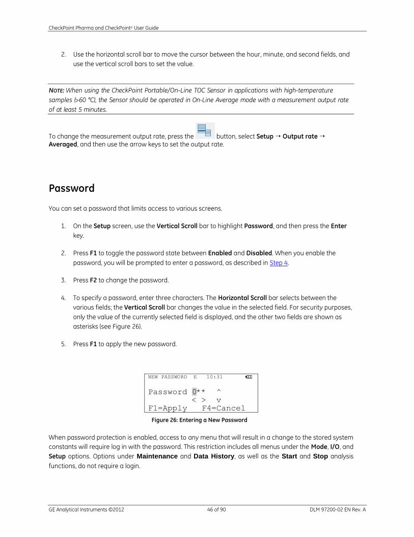
4. To specify a password, enter three characters. The Horizontal Scroll bar selects between the
various fields; the Vertical Scroll bar changes the value in the selected field. For security purposes,
only the value of the currently selected field is displayed, and the other two fields are shown as
asterisks (see Figure 26).
5. Press F1 to apply the new password.
NEW PASSWORD E 10:31
Password 0** ^ < > v F1=Apply F4=Cancel
Figure 26: Entering a New Password
When password protection is enabled, access to any menu that will result in a change to the stored system
constants will require log in with the password. This restriction includes all menus under the Mode, I/O, and
Setup options. Options under Maintenance and Data History, as well as the Start and Stop analysis
functions, do not require a login.
CheckPoint Pharma and CheckPointe User Guide
GE Analytical Instruments ©2012 47 of 90 DLM 97200-02 EN Rev. A
Clock
From the Clock screen, either press F1 to display the Set Date screen or F2 to display the Set Time screen.
The Horizontal Scroll bar selects between the various date or time fields; the Vertical Scroll bar changes
the value in the selected field.
Units of Measure
From the Units screen, press F1 to toggle the units of measure between temperature-compensated
conductivity (µS/cm), resistivity (M-cm), and RCond (US/CM) Temp (C).
Instrument Name
The Name screen displays the current Sensor name, and allows you to change the name. The Horizontal
Scroll bar moves the cursor left or right through the character. The Vertical Scroll bar changes the value of
the selected field.
LCD Contrast
The LCD Contrast screen allows you to change the contrast setting for the Sensor’s display. Use the
Vertical Scroll bar to change the value of the contrast setting, then press F1 to apply or F4 to cancel.
Language Selection
The Sensor supports menu display in English, Simplified Chinese, and Japanese. Use the Vertical Scroll bar
to select the language and then press the Enter button.
Inverse Display
By default, the Sensor’s display screen displays white characters on a blue background. You can invert the
display to show blue characters on a white background by pressing F1 on the Setup screen.
CheckPoint Pharma and CheckPointe User Guide
GE Analytical Instruments ©2012 48 of 90 DLM 97200-02 EN Rev. A
Maintenance Menu Options
Diagnostics
Pump: Displays the current state of the pump and lets you set the pump state on and off; also
provides mechanism to drain water from the Sensor before shipping.
Lamp: Displays the current state of the lamp and lets you set the lamp state on and off.
Conductivity Board/Analog Board: Displays and continuously updates the value of the current
channel. The unit of measure displayed depends on the channel selected (µS/cm, °C, or mV).
Options are the following: IC conductivity, IC temperature, TC conductivity, TC temperature, Cal
resistor 1, Cal resistor 2, and Ground
Save Service Data: Saves data and settings files to the USB flash memory drive.
4-20 mA: Displays the current state of analog output 1, 2, or 3 and lets you output either 4 mA or
20 mA through the selected analog output.
Alarms: Displays the current state of both alarms and lets you set the alarms’ state on and off.
Performing any of the diagnostics functions requires that the Sensor be in Standby mode. If the Sensor is
performing analysis and a diagnostic option is selected, analysis will be stopped (a confirmation screen will
be displayed).
Consumables
The Consumables screen displays the current state of the lamp, the pump tubing, and (if it is installed), the
battery.
To install new consumables, press F1, and then select F1 to install a new lamp or F2 to install a new pump.
The Horizontal Scroll bar selects between the day, month and year fields; the Vertical Scroll bar changes
the value in the selected field.
View Warnings and Errors
The View Error screen displays the Warnings and Errors history, with the most recent warnings and errors
at the top of the list. Use the Vertical Scroll bar to scroll through the list.
Press F1 to display the Remove Errors screen. To remove the current warning or error, press F1 and to
remove all warnings and errors in the error history list, press F2.
A list of possible warnings and errors is shown Step 1: Review Warnings Errors on page 73.

CheckPoint Pharma and CheckPointe User Guide
GE Analytical Instruments ©2012 49 of 90 DLM 97200-02 EN Rev. A
The TOC Chart and Customizing Data Display
Press until TOC Chart appears.
Customizing the Time Range
When viewing the data chart on the Main screen, you can customize the data display by pressing the
function keys as follows:
F1 - Display a chart with 20 minutes of data
F2 - Display a chart with 2 hours of data
F3 - Display a chart with 8 hours of data
F4 – display a chart with 24 hours of data
Customizing Data Resolution and the AutoScale Feature
Use the buttons to increase or decrease the concentration (in ppm or ppb) that is plotted on the y-axis
of the chart. If you continue to press the buttons, the Sensor cycles through the available ranges until
the AutoScale feature starts. The available ranges are as follows: 1, 2, 5, 10, 20, 50, 100, 200, and 500 ppb;
and 1 and 2 ppm. The TOC trend is calculated from data collected in 15-second intervals. With the
AutoScale feature, The CheckPoint automatically sets the chart to show the maximum concentration level
for the current data set. When AutoScale is active, the AutoScale Arrows display on the right side of the
screen. When AutoScale is not active, the AutoScale Arrows do not display.
Figure 27: AutoScale Arrows Indicate the AutoScale Feature is On
CheckPoint Pharma and CheckPointe User Guide
GE Analytical Instruments ©2012 50 of 90 DLM 97200-02 EN Rev. A
Figure 28: Absence of AutoScale Arrows Indicate the AutoScale Feature is Off
TOC Deviation Finder
The TOC Deviation Finder helps you rapidly identify the exact time of unexpected TOC deviations.
Use the buttons to shift the time range earlier (left arrow) or later (right arrow) to navigate
through the data history. This functionality can help you find specific data points quickly.
Next, press the button to toggle the crosshair on and off. The crosshair line displays at the
midpoint of the graph. When you press the button, the data point on the crosshair line is displayed
at the top of the data table. The tabular view provides more specific details about the data point.
Press the button to toggle between the graphical and tabular data displays.
Data History Export
When you press the button, the Sensor saves files containing the system constants and the data
history to a USB flash memory drive. The data history contains the following fields:
Table 3: : Data Saved in Exported Files
Field Value Format
Mode On-Line or Grab
Date and Time DD/MM/YYYY HH:MM
TOC [ppb]
Conductivity or
Resistivity
[μS/cm] or [MOhm–cm]
Temp [C]
Conductivity may be either temperature corrected or raw depending on the Units of Measure selection in
Setup.
For additional information regarding importing this data into a spreadsheet program, refer to ”Appendix B:
Importing Sensor Data into a Spreadsheet Program.”

CheckPoint Pharma and CheckPointe User Guide
GE Analytical Instruments ©2012 51 of 90 DLM 97200-02 EN Rev. A
Hardware Considerations
Battery Operation
The battery and charger system typically enable four to five hours of operation. Battery life may be
extended if the Sensor is in Analysis mode only intermittently.
Before using the battery in the Sensor, the battery must be fully charged in the external charger. When you
charge the battery for the first time, you should also calibrate the fuel gauge. To calibrate the fuel gauge
and charge the battery for use, place the battery in the charger and press the Calibrate button on the front
of the charger. The blue LED will flash to indicate that the battery is undergoing the recalibration cycle. The
external charger will first charge the battery, carry out a controlled discharge, and then recharge the
battery. At the end of this cycle, the blue LED will stay constant and your battery is ready for use. This
calibration/charging cycle will take approximately seven to ten hours.
Subsequently when you charge the battery, it will take approximately three hours. The battery does not
charge while it is inside the Sensor.
When the Sensor is operating on battery power, the battery icon displays in the upper right corner (see
Figure 29).
MAIN 10:31
F1=Mode F2=I/O
F3=Setup F4=Maintenance
Figure 29: The Battery Icon
When the Sensor is operating under battery power and is analyzing a sample, the battery icon alternates
with the analysis icon (see Figure 30).
MAIN 10:31 F1=Mode F2=I/O F3=Setup F4=Maintenance
Figure 30: The Analysis Icon
When the battery has been drained of power, the battery icon changes to the dead battery warning icon in
the upper right corner (see Figure 31). When analysis is not running, this icon flashes once per second.
When analysis is running, this icon alternates with the analysis icon once per second.
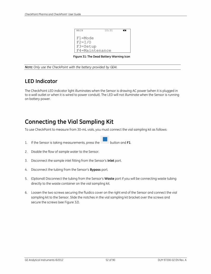
CheckPoint Pharma and CheckPointe User Guide
GE Analytical Instruments ©2012 52 of 90 DLM 97200-02 EN Rev. A
MAIN 10:31
F1=Mode F2=I/O F3=Setup F4=Maintenance
Figure 31: The Dead Battery Warning Icon
NOTE: Only use the CheckPoint with the battery provided by GEAI.
LED Indicator
The CheckPoint LED indicator light illuminates when the Sensor is drawing AC power (when it is plugged in to a wall outlet or when it is wired to power conduit). The LED will not illuminate when the Sensor is running on battery power.
Connecting the Vial Sampling Kit To use CheckPoint to measure from 30-mL vials, you must connect the vial sampling kit as follows:
1. If the Sensor is taking measurements, press the button and F1.
2. Disable the flow of sample water to the Sensor.
3. Disconnect the sample inlet fitting from the Sensor’s Inlet port.
4. Disconnect the tubing from the Sensor’s Bypass port.
5. (Optional) Disconnect the tubing from the Sensor’s Waste port if you will be connecting waste tubing
directly to the waste container on the vial sampling kit.
6. Loosen the two screws securing the fluidics cover on the right end of the Sensor and connect the vial
sampling kit to the Sensor. Slide the notches in the vial sampling kit bracket over the screws and
secure the screws (see Figure 32).
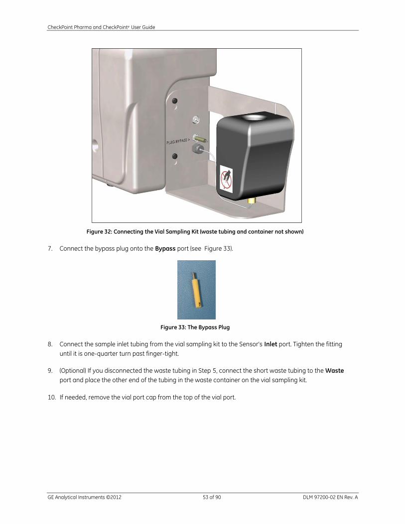
CheckPoint Pharma and CheckPointe User Guide
GE Analytical Instruments ©2012 53 of 90 DLM 97200-02 EN Rev. A
Figure 32: Connecting the Vial Sampling Kit (waste tubing and container not shown)
7. Connect the bypass plug onto the Bypass port (see Figure 33).
Figure 33: The Bypass Plug
8. Connect the sample inlet tubing from the vial sampling kit to the Sensor’s Inlet port. Tighten the fitting
until it is one-quarter turn past finger-tight.
9. (Optional) If you disconnected the waste tubing in Step 5, connect the short waste tubing to the Waste
port and place the other end of the tubing in the waste container on the vial sampling kit.
10. If needed, remove the vial port cap from the top of the vial port.
CheckPoint Pharma and CheckPointe User Guide
GE Analytical Instruments ©2012 54 of 90 DLM 97200-02 EN Rev. A
Storing the Sensor
When the Sensor will not be used for a prolonged time, the Sensor should be stored dry. Place the Sensor in
Grab Sample mode, make sure there is no sample water flowing to the Sensor, and begin a Grab analysis
to remove water from the Sensor. Alternatively, the Pump option on the Diagnostics screen can be used
without adding any measurements to the data history.
Remove the battery from the Sensor.
Printing
The Sensor will automatically detect if a printer is connected and will automatically print results for online,
grab, cond cal, and TOC cal when they complete. When operating in the On-Line mode, the printer prints
out the variables shown on the On-Line display screen. For example, if you are looking at an On-Line
display screen that is showing only the TOC result, then the time and only the TOC result prints.
CheckPoint Pharma and CheckPointe User Guide
GE Analytical Instruments ©2012 55 of 90 DLM 97200-02 EN Rev. A
Chapter 6 — Calibration and System Protocols
To calibrate the Sensor, you must use the optional CheckPoint vial sampling Kit. Refer to the Connecting
the Vial Sampling Kit on page 52 for instructions on connecting the vial sampling kit. For additional details
on the various calibration procedures, see the application note called “Calibration of the CheckPoint
Portable/On-Line TOC Sensor,” available from the www.geinstruments.com.
NOTE: If you are using the CheckPoint with a battery, make sure the battery has been fully charged in the
external charger before starting calibration.
Flow Rate Calibration
The flow rate calibration should be performed whenever the pump head is replaced. This procedure
assumes CheckPoint is installed on a pressurized water system.
1. If the Sensor is taking measurements, press the button and F1.
2. Shut off the sample supply line. Disconnect the tubing from the Sensor’s Waste port. If your Sensor
has a Bypass port, connect the waste line to the Bypass port. (Remove any other lengths of tubing
and fittings from the waste line.)
3. Connect the short length of waste tubing from the accessories kit to the Waste port.
4. Place the other end of the tubing in the graduated cylinder from the accessories kit.
5. Press the button.
6. Press F1 to select the Mode screen.
7. Press F1 to select Calibration.
8. Press F3 to select Flow Rate Calibration.
9. Press F1 to fill the pump outlet tubing with water (20 seconds). Insert the end of the flow rate
calibration drain tubing into a dry 10 mL graduated cylinder. If the waste line has not filled in the
allotted time, press F4 to cancel. Repeat from Steps 8 - 9 until the fluid path has been filled.
10. Press F1 to start the pump. The pump will operate at twice normal speed for 5 minutes.
11. Record the volume of water collected in the cylinder at the end of this 5-minute period (there should be
close to 5 mL). Enter this volume as prompted by the Sensor. Press F1 to temporarily apply new
settings. The Sensor will calculate a new volume per revolution for the pump.

CheckPoint Pharma and CheckPointe User Guide
GE Analytical Instruments ©2012 56 of 90 DLM 97200-02 EN Rev. A
12. To verify the new flow rate calibration, empty the cylinder and replace the flow rate calibration drain
tubing in the cylinder. The Sensor will pump water again for 5 minutes; the volume should be close to
5 mL. Press F1 to accept the new flow rate calibration.
There are no formal pass/fail criteria for the flow rate calibration, but GEAI recommends that the
calibration be accepted if the volume collected during the second five-minute test is between 4.8 and
5.2 mL.
13. After flow rate calibration is complete, disconnect the tubing from the Waste port and reconnect the
standard waste tubing.
Conductivity Calibration
Conductivity calibration should be performed after replacing the pump head if the Sensor is used for
conductivity or resistivity measurements. Conductivity calibration is not necessary for low level
applications where conductivity or resistivity values are not being used (conductivity <0.10 μS/cm or
resistivity >10 M with TOC < 20 ppb).
Remove the conductivity calibration standards from the refrigerator and allow them to warm to room
temperature (~ 1 hour) before starting calibration. Then, follow these steps:
1. Press the button.
2. Press F1 to select the Mode screen.
3. Press F1 to select Calibration.
4. Press F2 to select Conductivity.
5. Press F1 to select Conductivity Calibration.
6. Insert the 25 µS/cm HCl standard into the vial port.
7. Press F1 to start conductivity calibration. Sample is flushed through the Sensor and measurements on
the HCl solution begin.
When measurements are complete, the Sensor displays the mean measured and adjusted
temperature-corrected conductivity values. Press F1 to accept the calibration of F4 to cancel.
If a printer has been installed, the CheckPoint will print the results of each measurement upon
completion.
GEAI recommends that the calibration be applied if the average values are between 24-26 μS/cm and
the RSD is 0.5% or less.

CheckPoint Pharma and CheckPointe User Guide
GE Analytical Instruments ©2012 57 of 90 DLM 97200-02 EN Rev. A
8. If you also want to perform a calibration verification, continue with the following steps.
9. Press F1 to select Calibration.
10. Press F2 to select Conductivity.
11. Press F1 to select Conductivity Calibration.
12. Make sure the 25 µS/cm HCl standard is in the vial port. Press F1.
13. When the measurements are complete, record the values. Do not apply the calibration.
14. Calculate the Percent Difference via the following equation:
15. Acceptance criteria are as follows:
RSD values for Cell 1 and Cell 2 are 0.5% or less
% Diff values for Cell 1 and Cell 2 are ±2%
TOC Calibration
TOC Calibration should be performed after you have replaced the pump head. Remove the TOC calibration
standards from the refrigerator and allow them to warm to room temperature (~ 1 hour) before starting
calibration. Then, follow these steps:
1. Press the button.
2. Press F1 to select the Mode screen.
3. Press F1 to select Calibration.
4. Press F1 to select TOC.
5. Press F1 to select TOC Calibration.
6. Insert the reagent water blank into the vial port.
7. Press F1 to start TOC Calibration. Reagent water is flushed through the Sensor and measurements on
the blank begin.
% Diff =Measured Concentration - Expected Standard Concentration
Expected Standard Concentration----------------------------------------------------------------------------------------------------------------------------------------------------------------- 100%

CheckPoint Pharma and CheckPointe User Guide
GE Analytical Instruments ©2012 58 of 90 DLM 97200-02 EN Rev. A
8. When prompted, remove the reagent water blank and insert the 500 ppb Sucrose calibration standard
into the vial port.
9. Press F1.
10. The standard is flushed through the Sensor and measurements on the standard begin.
11. When measurements are complete, the Sensor displays calibration results, including the mean TOC
values for the blank and 500 ppb sucrose standard (measured) and the expected value (500 ppb plus
blank). Press F1 to accept the calibration or F4 to cancel. Use the button to scroll through the
complete calibration results.
If a printer has been installed, the CheckPoint will print the results of each measurement.
GEAI recommends that the calibration be applied if the TOC of the blank is 60 ppb, the measured
TOC of the 500 ppb standard is between 300-750 ppb, and the RSD of the replicate measurements of
the 500 ppb standard is 3%.
If a high reagent water blank is observed, this may be a result of a contaminated vial sampling kit. In
this case, the kit should be flushed with low TOC water (such as the second reagent water blank) using
the grab mode until low TOC values are observed; then the calibration should be repeated.
The TOC calibration is somewhat dependent on ambient temperature, and it is recommended that the
calibration be performed at the same ambient temperature at which the Sensor is normally operated.
12. If you also want to perform a calibration verification, continue with the following steps.
13. Press F4 until the Mode screen displays.
14. Press F2 to select Grab Sample.
15. Insert the reagent water blank into the vial port.
16. Press F1 to begin analysis.
17. After the vial has been analyzed, the results screen is displayed. Record the values of the average and
the RSD
18. Press F4 to continue.
19. Press F2 to select Grab Sample.
20. Insert the 500 ppb sucrose Calibration standard into the vial port.
21. Press F1 to begin analysis.
CheckPoint Pharma and CheckPointe User Guide
GE Analytical Instruments ©2012 59 of 90 DLM 97200-02 EN Rev. A
22. After the vial has been analyzed, the results screen is displayed. Record the values of the average and
the RSD.
23. Calculate the Expected value as 500 ppb + the average value of the reagent water blank and record
the value.
24. Calculate the Percent Difference via the following equation:
25. Acceptance criteria are as follows:
RSD of the replicate measurements of the 500 ppb standard is 3%
% Diff ±10%
Cleaning the Vial Sampling Kit
After performing the TOC or conductivity calibration, the Vial Sampling Kit should be cleaned prior to
storage. The recommended procedure for cleaning the kit after the TOC calibration is as follows:
1. Insert the reagent water blank into the vial port and perform a grab sample analysis.
2. Remove the reagent water blank vial and repeat the grab sample analysis without any vial in the port
to dry the calibration kit.
3. Replace the vial port dust cover, remove the calibration line from the Analyzer and connect the line to
the storage fitting on the vial sampling kit.
TOC Autozero
Because the CheckPoint calculates TOC from the difference in conductivity measurements before and after
UV oxidation, it is critical that the two conductivity cells match. The TOC autozero is an adjustment of the
Cell 2 offset to match the conductivity of cell 1 when the UV lamp is off (no oxidation). The autozero can be
performed either manually or scheduled for a time in which the water system is relatively stable. The
scheduled autozero calibration takes 1 hour, and the manual autozero calibration takes 30 minutes. The
Sensor should be used in on-line mode until the readings are stable before performing an Autozero.
% Diff =Measured Concentration - Expected Standard Concentration
Expected Standard Concentration----------------------------------------------------------------------------------------------------------------------------------------------------------------- 100%
CheckPoint Pharma and CheckPointe User Guide
GE Analytical Instruments ©2012 60 of 90 DLM 97200-02 EN Rev. A
Performing a Manual Autozero
When the autozero is performed manually, the lamp is turned back on after the autozero is completed. If
analysis is immediately started, the first few measurements may drift as the temperature inside the Sensor
warms up.
1. If the Sensor is taking measurements, press the button.
2. Press the button.
3. Press F1 to select the Mode screen.
4. Press F1 to select Calibration.
5. Press F1 to select TOC
6. Press F2 to select Autozero
7. Press F2 to select Run Autozero. The Sensor will record conductivity measurements from both cells
with the UV lamp off. Once stable readings are obtained, the offset for Cell 2 is adjusted to match Cell 1
and the new offset is verified by repeating the conductivity measurements with the lamp off.
A message is displayed upon completion of the autozero. If stable conductivity readings were not
observed during the calibration, the calibration will be stopped and a warning message displayed.
Scheduling an Autozero
1. Press the button.
2. Press F1 to select the Mode screen.
3. Press F1 to select Calibration.
4. Press F1 to select TOC
5. Press F2 to select Autozero
6. Press F1 to select Set Schedule. Enable Autozero if it is disabled. Then, set the Interval (1-7 days) and
the time.
7. The date and time for the next scheduled autozero will be displayed. When the CheckPoint is first
installed, daily Autozeros are recommended. After a few weeks, the interval can be increased (such as,
once a week). The frequency should be set back to daily if the Sensor is moved to a different water
system or if the composition of the water system changes.

CheckPoint Pharma and CheckPointe User Guide
GE Analytical Instruments ©2012 61 of 90 DLM 97200-02 EN Rev. A
Conductivity Match
The conductivity match is an adjustment of the offsets for both conductivity cells to match the
conductivity/resistivity of a reference meter. To perform this calibration, we recommended that the
CheckPoint be installed and operated on the water system equipped with a reference
conductivity/resistivity meter for at least 24 hours.
1. Press the button.
2. Press F1 to select the Mode screen.
3. Press F1 to select Calibration.
4. Press F2 to select Conductivity.
5. Press F3 to select Conductivity Match.
6. Record the average Conductivity/resistivity values from the reference meter and enter this value in the
TOC match screen.
7. Press F1 to accept the new offsets.
It may be necessary repeat the conductivity match periodically.
TOC Match
The TOC calibration described previously is a high level adjustment of the TOC gain. For low-level TOC
measurements (< 5 ppb) a more critical calibration is the TOC offset or TOC match. For this calibration,
CheckPoint Sensor is installed on a water system along with a reference analyzer. After stable TOC
measurements are obtained from both the Sensor and the reference analyzer, an offset is applied to
Sensor’s TOC measurements to match the reference analyzer. To perform this calibration, we recommend
that the Sensor be installed and operated on the water system for at least 24 hours and that a TOC
autozero be either scheduled or performed manually. After the autozero, allow the CheckPoint to operate
for 2-3 hours prior to performing the match.
1. Press the button.
2. Press F1 to select the Mode screen.
3. Press F1 to select Calibration.
4. Press F1 to select TOC.
5. Press F3 to select TOC Match.
CheckPoint Pharma and CheckPointe User Guide
GE Analytical Instruments ©2012 62 of 90 DLM 97200-02 EN Rev. A
6. Record the average TOC values from the reference analyzer and enter this value in the TOC match
screen.
7. Press F1 to accept the new TOC offset.
It may be necessary to repeat the TOC match periodically, particularly if the level of TOC or the types of
organic compounds in the water system change or if Sensor is moved to a different water system.
Automatic Offset
During on-line measurements, the Sensor monitors the conductivity/resistivity measurement from cell 1. If
the conductivity drops below 0.0546 µS/cm (resistivity goes above 18.3 megaohm cm), the offsets for both
cells are adjusted to correct the conductivity readings
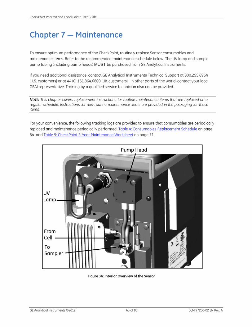
CheckPoint Pharma and CheckPointe User Guide
GE Analytical Instruments ©2012 63 of 90 DLM 97200-02 EN Rev. A
Chapter 7 — Maintenance
To ensure optimum performance of the CheckPoint, routinely replace Sensor consumables and
maintenance items. Refer to the recommended maintenance schedule below. The UV lamp and sample
pump tubing (including pump heads) MUST be purchased from GE Analytical Instruments.
If you need additional assistance, contact GE Analytical Instruments Technical Support at 800.255.6964
(U.S. customers) or at 44 (0) 161.864.6800 (UK customers). In other parts of the world, contact your local
GEAI representative. Training by a qualified service technician also can be provided.
NOTE: This chapter covers replacement instructions for routine maintenance items that are replaced on a
regular schedule. Instructions for non-routine maintenance items are provided in the packaging for those items.
For your convenience, the following tracking logs are provided to ensure that consumables are periodically
replaced and maintenance periodically performed: Table 4: Consumables Replacement Schedule on page
64 and Table 5: CheckPoint 2-Year Maintenance Worksheet on page 71.
Figure 34: Interior Overview of the Sensor
CheckPoint Pharma and CheckPointe User Guide
GE Analytical Instruments ©2012 64 of 90 DLM 97200-02 EN Rev. A
Table 4: Consumables Replacement Schedule
Description Typical Operating Life
UV lamp 6 months
Pump tubing (with pump heads) 6 months
Inline filter (optional) Replace as needed (depends on water quality)
Replacing the Sample Pump Head and Tubing
The tubing for the sample pump loses elasticity over time and must be replaced semi-annually to ensure
proper flow rates; the tubing cannot be replaced independently of the sample pump head, and is provided
as a kit with new pump heads. The sample pump tubing and pump head must be purchased from
GE Analytical Instruments. Use of tubing from other sources or failure to replace the tubing on the
prescribed replacement schedule will affect Sensor functionality. Instructions and illustrations for this
procedure also can be found in the Sensor’s Quick Setup Guide.
Warning
Installation of the sample pump tubing and pump heads requires
access to the inside of the Sensor. To avoid potentially dangerous
shock, disconnect the power cord before opening the Sensor’s front
panel.
Have paper towels available during the procedure in case water leaks from the old pump heads during the
removal process.
1. If the Sensor is taking measurements, press the button to stop analysis.
2. Power off the Sensor by pressing the button for three seconds. Then, turn off the breaker,
unplug the power cord, or remove the battery.
3. Stop the flow of sample water to the Sensor.
4. Disconnect the sample inlet and waste lines from the Sensor.
5. Remove the fluidics cover.
6. Locate the sample pump head.
CheckPoint Pharma and CheckPointe User Guide
GE Analytical Instruments ©2012 65 of 90 DLM 97200-02 EN Rev. A
7. Remove the tubing from the two barbs.
8. Use a small Phillips screwdriver (from the accessories kit) to loosen the two screws that secure the
pump head. Remove the screws and retain them.
9. Pull the pump head straight out and off the shaft. Dispose of the old pump head. Use a paper towel to
clean any dripping that occurs.
10. Remove the new pump head from the packaging. Slide the pump head onto the shaft and push it all
the way back, making sure the set pins are seated properly. You may need to “walk” the pump head
onto the shaft. The shaft is a “D” and must align properly with the pumps. Orient the pump head with
the shorter tubing on the left. Turn the head until it aligns with the set pins.
11. Replace and secure the two Phillips screws.
Warning
Do not over-tighten the pump head screws: over-tightening the
screws could result in damaging the pump head!
12. Reattach the sample pump tubing.
13. Record the installation date for the pump heads on the Maintenance Worksheet. See Table 5:
CheckPoint 2-Year Maintenance Worksheet on page 71.
14. If you need to replace the UV lamp, follow the procedure below. Otherwise, close and secure the
fluidics cover.
15. Reconnect the sample inlet and waste lines to the Sensor.
16. Restore power to the Sensor and then press and hold the to turn on the Sensor.
17. Enter the installation date for the sample pump head as described in “Setting the Installation Date for
New Consumables” below.
18. Perform the Flow Rate Calibration procedure, as described on page 55.

CheckPoint Pharma and CheckPointe User Guide
GE Analytical Instruments ©2012 66 of 90 DLM 97200-02 EN Rev. A
Changing the UV Lamp
The intensity of the UV lamp, particularly the emission of short-wavelength radiation, decreases over time.
Replace the lamp after every six months of operation. Instructions and illustrations for this procedure also
can be found in the Sensor’s Quick Setup Guide.
Warning
Installation of the UV lamp requires access to the inside of the Sensor.
To avoid potentially dangerous shock, disconnect the power cord and
remove the battery before opening the Sensor’s case.
Warning
The UV lamp contains mercury and may be considered hazardous material in your
local area. Dispose of the UV lamp in accordance with federal, state, or local
government regulations.
Warning
Should the UV lamp become broken or damaged, it should be handled in
accordance with your organization's toxic waste handling procedure and disposed
of in accordance with federal, state, or local government regulations.
NOTE: A cotton glove for wearing during the installation is included with the
replacement UV lamp. Wear this glove to avoid leaving fingerprints on the quartz window of the lamp. Fingerprints absorb UV radiation and decrease the performance of the oxidation reactor. If necessary, use methanol to remove any fingerprints before installing the new lamp.

CheckPoint Pharma and CheckPointe User Guide
GE Analytical Instruments ©2012 67 of 90 DLM 97200-02 EN Rev. A
To replace the UV lamp:
1. If the Sensor is taking measurements, press the button to stop analysis.
2. Power off the Sensor by pressing the button for three seconds. Then, turn off the breaker,
unplug the power cord, and remove the battery, if present.
3. Stop the flow of sample water to the Sensor.
4. Disconnect the sample inlet and waste lines.
5. Remove the fluidics cover.
6. Locate the UV lamp enclosure. The UV enclosure has a brass nut and a gray wire with a black
connector extending from the nut.
7. Disconnect the black power connector from the power supply by turning the connector and then
carefully pulling the two halves of the plug apart.
8. Loosen the brass nut on the UV enclosure. The nut should only be finger-tight; do not use a wrench.
9. Slowly slide the UV lamp out of the enclosure.
10. Put on the glove provided with the new UV lamp, to avoid leaving fingerprints on the quartz window of
the lamp. Remove the new lamp from the packet and the nut and ferrules from the zip-top bag.
11. Slide the nut up the lamp housing (toward the connector cord), and then slide the ferrules up the lamp
housing, until they are level with the black heat shrink tubing. Be careful when inserting the lamp into
the Sensor as the nut and ferrules may slide off. Refer to Figure 35 and Figure 36 for proper orientation
of the ferrules.
Heat shrink tubing
Brass nut
Ferrules Power connector
Figure 35: Relative Positioning of Components in the UV Lamp Assembly

CheckPoint Pharma and CheckPointe User Guide
GE Analytical Instruments ©2012 68 of 90 DLM 97200-02 EN Rev. A
Figure 36: UV Lamp Ferrule Orientation Detail
12. Carefully slide the lamp assembly into the enclosure. Stop if you feel any resistance, and realign the
lamp in the reactor. Make sure the black heat tubing is flush against the brass-colored nut.
13. Tighten the brass-colored nut finger-tight. While tightening the nut, make sure the heat shrink tubing
remains flush against the nut (Figure 35). Do NOT use a wrench.
14. Connect the power connector to the bulkhead by aligning the slot on the connector with the slot on
the power supply. Tighten the connector screw. Gently pull on the power connector to make sure it is
securely attached to the power supply.
15. Record the installation date for the UV lamp in the Maintenance Worksheet. See Table 5: CheckPoint 2-
Year Maintenance Worksheet on page 71.
16. If you need to replace the sample pump head, go to the Replacing the Sample Pump Head and Tubing
instructions on page 64. Otherwise, close and secure the fluidics cover.
17. Restore power to the Sensor and then press and hold the to turn on the Sensor.
18. Enter the installation date for the UV lamp as described in “Setting the Installation Date for New
Consumables” below.
Changing the Inline Filter Element
To help prevent clogging, a filter may be installed on the sample inlet line. The lifetime of the filter element
depends on the level of particles in the water samples. To replace the element, follow these steps:
1. Using two wrenches, loosen the end cap of the filter by turning the wrenches in opposite directions
(see Figure 37).
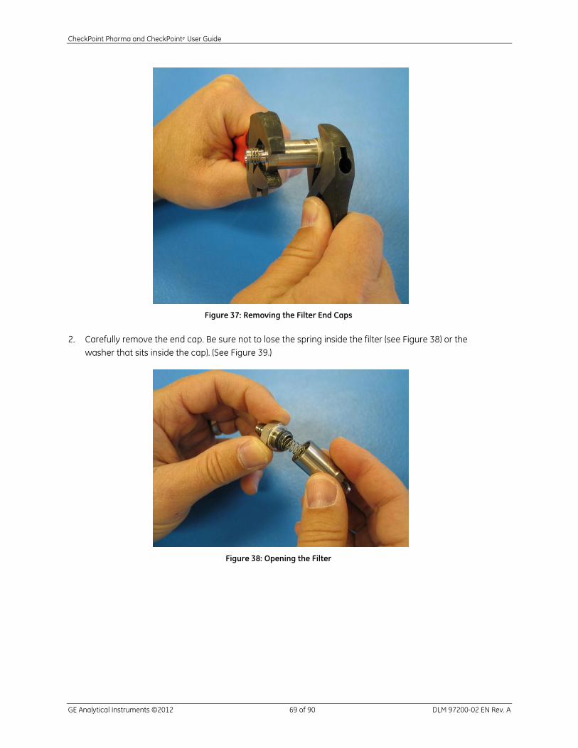
CheckPoint Pharma and CheckPointe User Guide
GE Analytical Instruments ©2012 69 of 90 DLM 97200-02 EN Rev. A
Figure 37: Removing the Filter End Caps
2. Carefully remove the end cap. Be sure not to lose the spring inside the filter (see Figure 38) or the
washer that sits inside the cap). (See Figure 39.)
Figure 38: Opening the Filter

CheckPoint Pharma and CheckPointe User Guide
GE Analytical Instruments ©2012 70 of 90 DLM 97200-02 EN Rev. A
Figure 39: The Washer Inside the Filter Cap
3. Remove the filter element and discard.
4. Remove the new filter element from the packaging.
5. Reassemble the filter. Put the new filter element into the filter (hollow-end first) and put the spring on
top of the element. Place the washer inside the cap. For correct stacking order, see Figure 40.
6. Using the two wrenches, secure the filter cap by turning the wrenches in opposite directions.
Figure 40: Proper Filter Stacking Order
Setting the Installation Date for New Consumables
The Consumables screen displays the current state of the lamp, the pump tubing, and (if it is installed), the
battery. From the Maintenance menu, select the Consumables option.
To install new consumables, press F1, and then select F1 to install a new lamp or F2 to install a new pump.
The Horizontal Scroll bar selects between the day, month and year fields; the Vertical Scroll bar changes
the value in the selected field.

CheckPoint Pharma and CheckPointe User Guide
GE Analytical Instruments ©2012 71 of 90 DLM 97200-02 EN Rev. A
Cleaning the Sensor
You can clean the external housing of the Sensor with a damp cloth using water or non-abrasive cleaners.
Turn off power to the Sensor and disconnect it from main power or remove the battery prior to cleaning.
Do not spray liquids directly on the Sensor. Wipe dry with a clean, soft cloth.
The screen may be cleaned with a soft cloth or cotton pad. Isopropyl Alcohol may be used, but insure that
all solvent residue is removed. Clean any condensation or moisture from any source immediately. If the
touch screen becomes fractured or cracked, do not touch it and call technical support.
Cleaning the Vial Sampling Kit
The vial sampling kit should be rinsed before and after use to remove residue from samples or standards
that may remain on the wetted parts. This can easily be performed by running grab samples through the
sampler from a vial of DI water for 15 minutes or until sample readings stabilize.
Table 5: CheckPoint 2-Year Maintenance Worksheet
Item Period Installation Date Notes
UV Lamp 6 months
Pump Heads 6 months
Pump Heads 12 months
UV Lamp 12 months
UV Lamp 18 months
Pump Heads 18 months
Pump Heads 24 months
UV Lamp 24 months

CheckPoint Pharma and CheckPointe User Guide
GE Analytical Instruments ©2012 72 of 90 DLM 97200-02 EN Rev. A
This page is intentionally left blank.
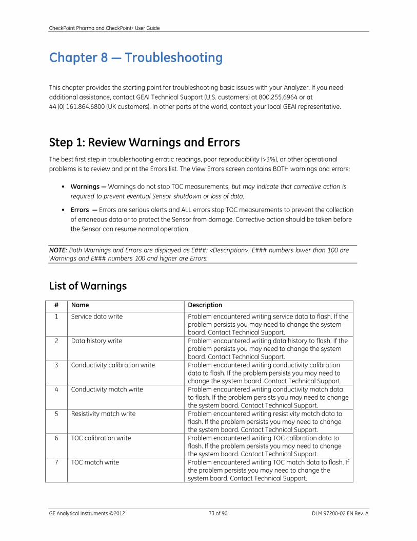
CheckPoint Pharma and CheckPointe User Guide
GE Analytical Instruments ©2012 73 of 90 DLM 97200-02 EN Rev. A
Chapter 8 — Troubleshooting
This chapter provides the starting point for troubleshooting basic issues with your Analyzer. If you need
additional assistance, contact GEAI Technical Support (U.S. customers) at 800.255.6964 or at
44 (0) 161.864.6800 (UK customers). In other parts of the world, contact your local GEAI representative.
Step 1: Review Warnings and Errors
The best first step in troubleshooting erratic readings, poor reproducibility (>3%), or other operational
problems is to review and print the Errors list. The View Errors screen contains BOTH warnings and errors:
• Warnings — Warnings do not stop TOC measurements, but may indicate that corrective action is
required to prevent eventual Sensor shutdown or loss of data.
• Errors — Errors are serious alerts and ALL errors stop TOC measurements to prevent the collection
of erroneous data or to protect the Sensor from damage. Corrective action should be taken before
the Sensor can resume normal operation.
NOTE: Both Warnings and Errors are displayed as E###: <Description>. E### numbers lower than 100 are
Warnings and E### numbers 100 and higher are Errors.
List of Warnings
# Name Description
1 Service data write Problem encountered writing service data to flash. If the problem persists you may need to change the system board. Contact Technical Support.
2 Data history write Problem encountered writing data history to flash. If the problem persists you may need to change the system board. Contact Technical Support.
3 Conductivity calibration write Problem encountered writing conductivity calibration data to flash. If the problem persists you may need to change the system board. Contact Technical Support.
4 Conductivity match write Problem encountered writing conductivity match data to flash. If the problem persists you may need to change the system board. Contact Technical Support.
5 Resistivity match write Problem encountered writing resistivity match data to flash. If the problem persists you may need to change the system board. Contact Technical Support.
6 TOC calibration write Problem encountered writing TOC calibration data to flash. If the problem persists you may need to change the system board. Contact Technical Support.
7 TOC match write Problem encountered writing TOC match data to flash. If the problem persists you may need to change the system board. Contact Technical Support.

CheckPoint Pharma and CheckPointe User Guide
GE Analytical Instruments ©2012 74 of 90 DLM 97200-02 EN Rev. A
8 Auto-zero write Problem encountered writing Auto-zero data to flash. If the problem persists you may need to change the system board. Contact Technical Support.
9 Auto-offset write Problem encountered writing Auto-offset data to flash. If the problem persists you may need to change the system board. Contact Technical Support.
10 Flow rate calibration write Problem encountered writing flow rate calibration data to flash. If the problem persists you may need to change the system board. Contact Technical Support.
11 Data history queue overflow Problem encountered writing data history to flash. If the problem persists you may need to change the system board. Contact Technical Support.
12 Service data queue overflow Problem encountered writing service data to flash. If the problem persists you may need to change the system board. Contact Technical Support.
13 UV lamp should be replaced soon Lamp expiration date is 10 days or less away.
14 Pump tubing should be replaced soon Pump tubing expiration date is 10 days or less away.
15 Battery needs recalibration Battery is indicating that it needs to be recalibrated. Put battery in external charger and press the Recalibrate button.
16 Invalid lamp install date Lamp install date is in the future (later than the current instrument time). This can be caused by changing the system clock to an earlier time or entering an invalid time when installing the lamp.
17 Invalid pump install date Pump install date is in the future (later than the current instrument time). This can be caused by changing the system clock to an earlier time or entering an invalid time when installing the pump.
18 Auto-zero failed Readings not stable enough to complete Auto-zero.
19 TOC value Invalid TOC warning. TOC reading is above the 1000 ppb limit.
List of Errors
# Name Description
102 Invalid TOC value Invalid TOC error. TOC reading is negative. Check UV lamp, recalibrate.
103 System constants write Problem encountered writing system constants to flash. If the problem persists you may need to change the system board. Contact Technical Support.
104 System constants queue overflow Problem encountered writing system constants to flash. If the problem persists you may need to change the system board. Contact Technical Support.
105 Battery drawing power on AC Power supply problem. Battery is showing current draw while AC is connected.
106 Excessive noise on cell 1 Data rejection on cell 1 exceeds 90%, indicates problem with cell or conductivity board.
107 Excessive noise on cell 2 Data rejection on cell 2 exceeds 90%, indicates problem with cell or conductivity board.

CheckPoint Pharma and CheckPointe User Guide
GE Analytical Instruments ©2012 75 of 90 DLM 97200-02 EN Rev. A
108 Analog board communications Unable to communicate with EEPROM on conductivity board at power on. Check cable connections between conductivity board and system board. If problem persists, replace the conductivity board.
109 System constant read Bad record encountered reading the system constants file. Contact technical support. The most likely cause is unexpected power outage during write (Shutting down without using the Off button). System constant will be reset to default value. If this error occurs frequently, this may indicate problems with flash on the system board. You will need to restore constants to correct the problem.
110 Battery over temperature Battery is reporting over temperature condition. Check that the fan is running the fan outlet and air intakes are not blocked.
Step 2: Basic Troubleshooting Steps
Downloading Service Data
GEAI Technical Support may ask to review the Sensor’s service data while assisting with troubleshooting.
To download the service data, make sure a USB flash memory drive is attached to the Sensor’s USB port
(located behind I/O cover) and follow these steps:
1. Press the button.
2. Press F4 to select the Maintenance screen.
3. Press F1 to select the Diagnostics screen. When the Diagnostics menu displays, the Sensor will
prompt you to stop analysis.
4. Use the to scroll down to the Save Service Data option, and then press the button.
5. The data files are saved to the USB flash memory drive. If Technical Support has asked to review the
file, you can take the flash memory drive to your personal computer and attach the service data file to
an email.
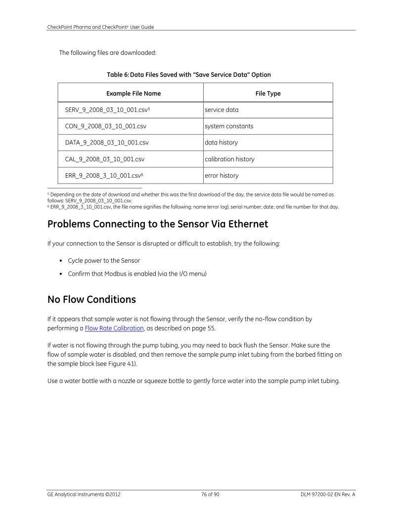
CheckPoint Pharma and CheckPointe User Guide
GE Analytical Instruments ©2012 76 of 90 DLM 97200-02 EN Rev. A
The following files are downloaded:
Table 6: Data Files Saved with “Save Service Data” Option
Example File Name File Type
SERV_9_2008_03_10_001.csv5 service data
CON_9_2008_03_10_001.csv system constants
DATA_9_2008_03_10_001.csv data history
CAL_9_2008_03_10_001.csv calibration history
ERR_9_2008_3_10_001.csv6 error history
5 Depending on the date of download and whether this was the first download of the day, the service data file would be named as follows: SERV_9_2008_03_10_001.csv. 6 ERR_9_2008_3_10_001.csv, the file name signifies the following: name (error log); serial number; date; and file number for that day.
Problems Connecting to the Sensor Via Ethernet
If your connection to the Sensor is disrupted or difficult to establish, try the following:
• Cycle power to the Sensor
• Confirm that Modbus is enabled (via the I/O menu)
No Flow Conditions
If it appears that sample water is not flowing through the Sensor, verify the no-flow condition by
performing a Flow Rate Calibration, as described on page 55.
If water is not flowing through the pump tubing, you may need to back flush the Sensor. Make sure the
flow of sample water is disabled, and then remove the sample pump inlet tubing from the barbed fitting on
the sample block (see Figure 41).
Use a water bottle with a nozzle or squeeze bottle to gently force water into the sample pump inlet tubing.

CheckPoint Pharma and CheckPointe User Guide
GE Analytical Instruments ©2012 77 of 90 DLM 97200-02 EN Rev. A
Figure 41: Removing the Sample Pump Inlet Tubing
Checking for Leaks
Leaks and or bubbles in the Sensor may cause noisy data. To safeguard against leaks, confirm that all
fittings are tight, and make sure the sample pump inlet tubing is securely seated on the barb on the
sample block. Also check for signs of moisture in the fluidics side of the Sensor.
Step 3: Returning the Sensor to GEAI
Several precautions must be followed to ensure that the Sensor is not damaged during shipment. If the
original shipping container has not been retained, contact GE Analytical Instruments at 1-888-245-2595 or
303-444-2009 (U.S. customers), or at 44 (0) 161-864-6800 (UK customers) to order shipping supplies. In
other parts of the world, contact your local GEAI representative. Under no circumstances, should the
Sensor be packed in anything other than the original shipping container.
To prepare the Sensor for shipping, do the following:
1. If the Sensor is taking measurements, press the button to stop analysis.
2. Stop the flow of sample water to the Sensor.
3. Disconnect the sample inlet, bypass, and waste outlet tubing from the Sensor.
4. Select the Maintenance menu.

CheckPoint Pharma and CheckPointe User Guide
GE Analytical Instruments ©2012 78 of 90 DLM 97200-02 EN Rev. A
5. Select Diagnostics.
6. Select Pump.
7. Turn the pump on and let it run for 10 minutes.
8. Stop the pump.
9. Power off the Sensor by pressing the button.
10. Then, turn off the breaker, unplug the power cord, or remove the battery.
NOTE: You must remove the battery before shipping the Sensor.
11. Disconnect any wiring or cables connected to the I/O ports, including an Ethernet cable or 4-20 mA
wiring (if applicable).
12. If the Sensor is mounted to a wall bracket, remove it from the bracket by gently but firmly pushing up
on the Sensor until it comes free of the bracket.
13. The Sensor is now ready to be packaged in the original shipping materials.
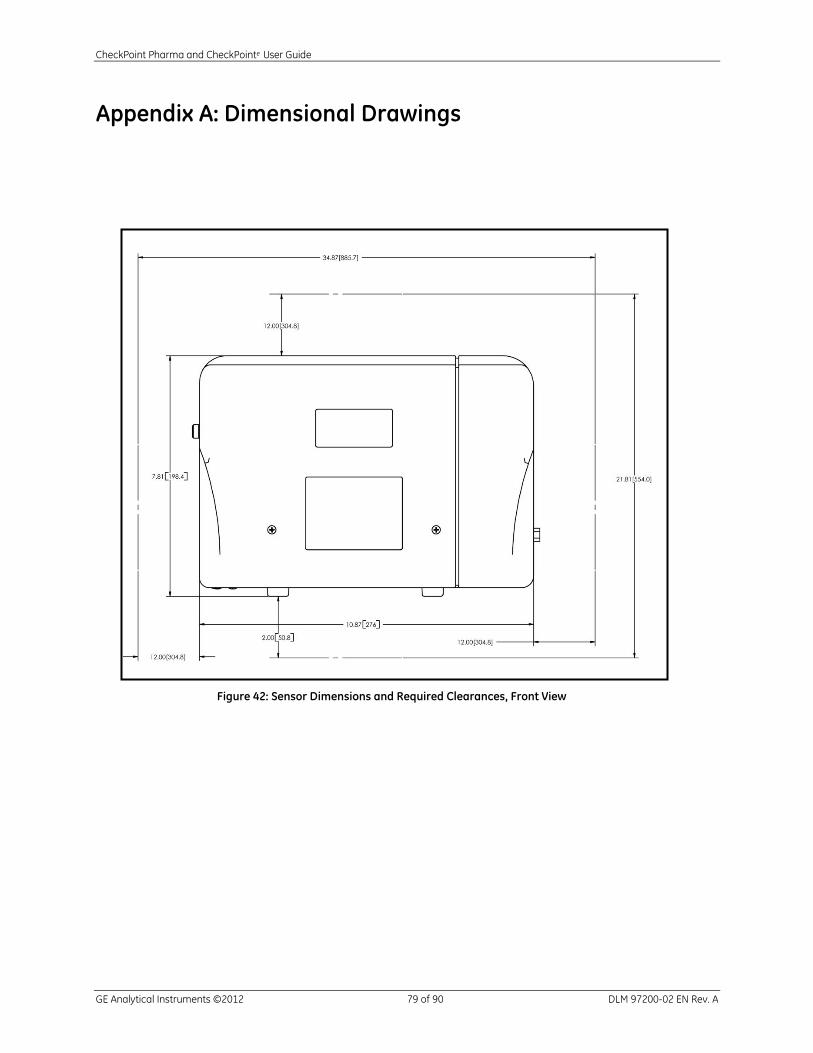
CheckPoint Pharma and CheckPointe User Guide
GE Analytical Instruments ©2012 79 of 90 DLM 97200-02 EN Rev. A
Appendix A: Dimensional Drawings
Figure 42: Sensor Dimensions and Required Clearances, Front View

CheckPoint Pharma and CheckPointe User Guide
GE Analytical Instruments ©2012 80 of 90 DLM 97200-02 EN Rev. A
Figure 43: Sensor Dimensions and Required Clearances, Left Side View
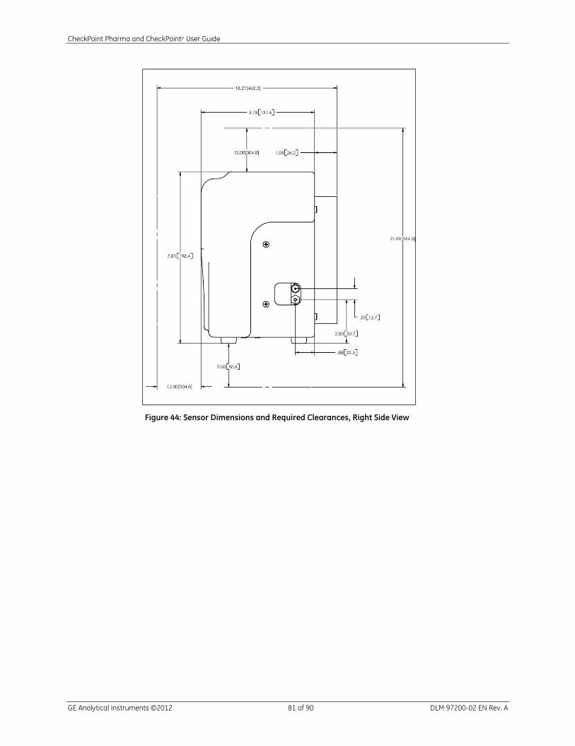
CheckPoint Pharma and CheckPointe User Guide
GE Analytical Instruments ©2012 81 of 90 DLM 97200-02 EN Rev. A
Figure 44: Sensor Dimensions and Required Clearances, Right Side View
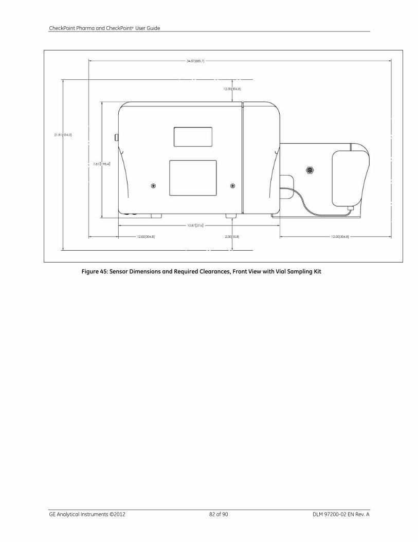
CheckPoint Pharma and CheckPointe User Guide
GE Analytical Instruments ©2012 82 of 90 DLM 97200-02 EN Rev. A
Figure 45: Sensor Dimensions and Required Clearances, Front View with Vial Sampling Kit
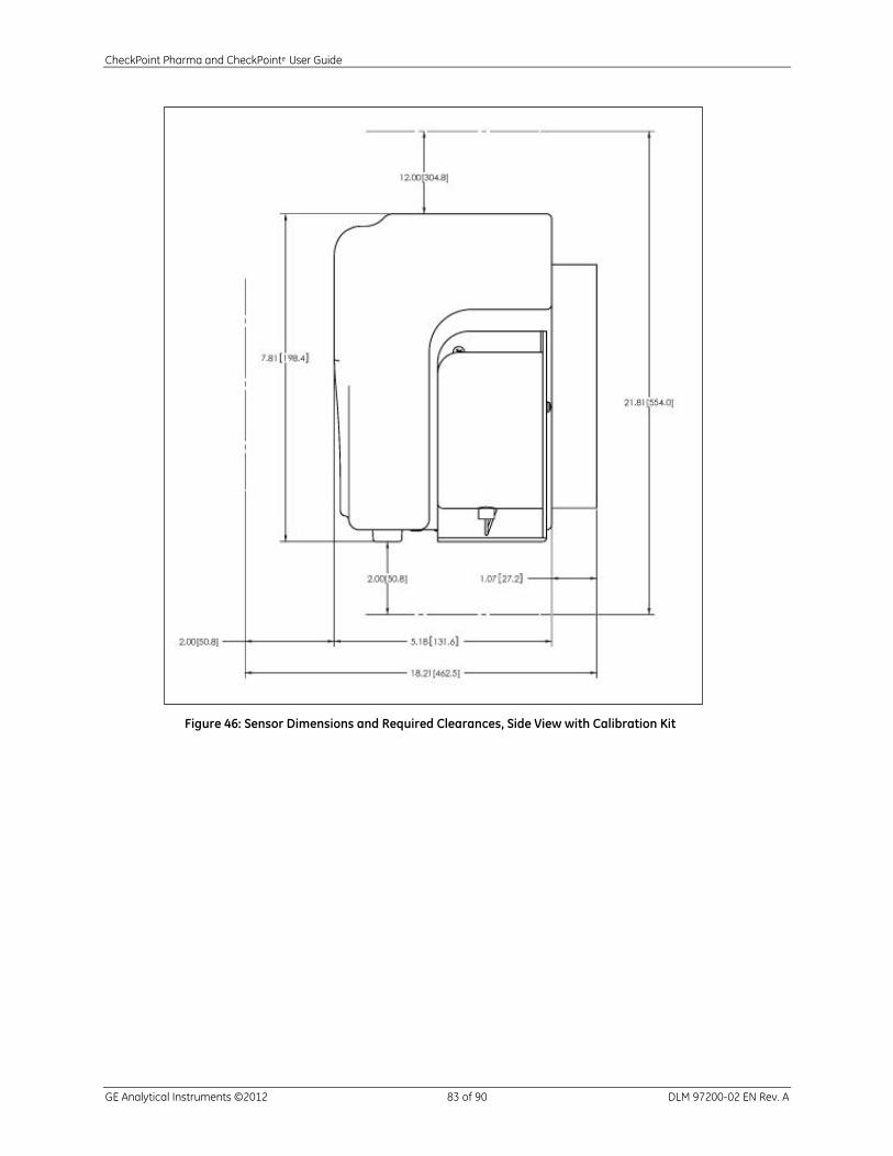
CheckPoint Pharma and CheckPointe User Guide
GE Analytical Instruments ©2012 83 of 90 DLM 97200-02 EN Rev. A
Figure 46: Sensor Dimensions and Required Clearances, Side View with Calibration Kit
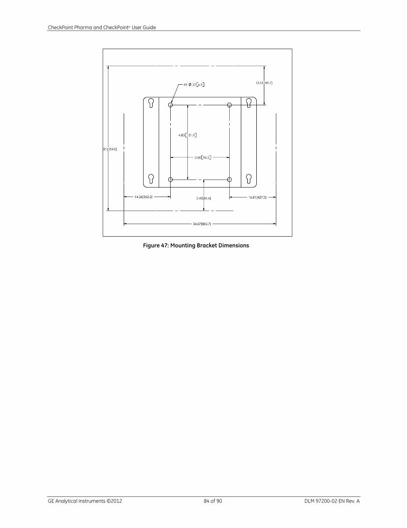
CheckPoint Pharma and CheckPointe User Guide
GE Analytical Instruments ©2012 84 of 90 DLM 97200-02 EN Rev. A
Figure 47: Mounting Bracket Dimensions
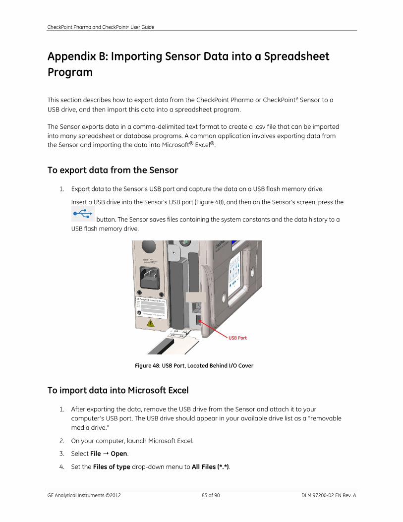
CheckPoint Pharma and CheckPointe User Guide
GE Analytical Instruments ©2012 85 of 90 DLM 97200-02 EN Rev. A
Appendix B: Importing Sensor Data into a Spreadsheet
Program
This section describes how to export data from the CheckPoint Pharma or CheckPointe Sensor to a
USB drive, and then import this data into a spreadsheet program.
The Sensor exports data in a comma-delimited text format to create a .csv file that can be imported
into many spreadsheet or database programs. A common application involves exporting data from
the Sensor and importing the data into Microsoft® Excel®.
To export data from the Sensor
1. Export data to the Sensor’s USB port and capture the data on a USB flash memory drive.
Insert a USB drive into the Sensor’s USB port (Figure 48), and then on the Sensor’s screen, press the
button. The Sensor saves files containing the system constants and the data history to a
USB flash memory drive.
Figure 48: USB Port, Located Behind I/O Cover
To import data into Microsoft Excel
1. After exporting the data, remove the USB drive from the Sensor and attach it to your
computer’s USB port. The USB drive should appear in your available drive list as a “removable
media drive.”
2. On your computer, launch Microsoft Excel.
3. Select File Open.
4. Set the Files of type drop-down menu to All Files (*.*).
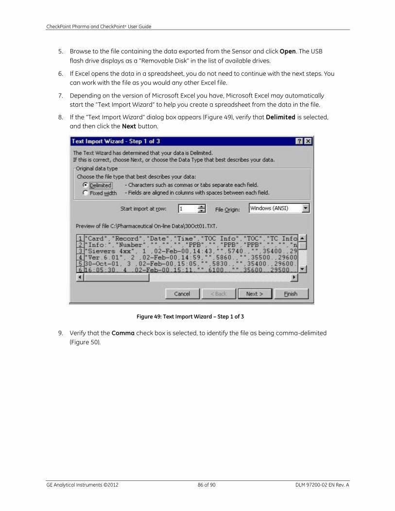
CheckPoint Pharma and CheckPointe User Guide
GE Analytical Instruments ©2012 86 of 90 DLM 97200-02 EN Rev. A
5. Browse to the file containing the data exported from the Sensor and click Open. The USB
flash drive displays as a “Removable Disk” in the list of available drives.
6. If Excel opens the data in a spreadsheet, you do not need to continue with the next steps. You
can work with the file as you would any other Excel file.
7. Depending on the version of Microsoft Excel you have, Microsoft Excel may automatically
start the “Text Import Wizard” to help you create a spreadsheet from the data in the file.
8. If the “Text Import Wizard” dialog box appears (Figure 49), verify that Delimited is selected,
and then click the Next button.
Figure 49: Text Import Wizard – Step 1 of 3
9. Verify that the Comma check box is selected, to identify the file as being comma-delimited
(Figure 50).

CheckPoint Pharma and CheckPointe User Guide
GE Analytical Instruments ©2012 87 of 90 DLM 97200-02 EN Rev. A
Figure 50: Text Import Wizard – Step 2 of 3
10. Microsoft Excel shows a preview of the data that will be imported. You can highlight a column
and assign a Column data format (Figure 51). Click Finish to continue.
Figure 51: Text Import Wizard – Step 3 of 3
A new spreadsheet containing your exported data opens. You can now modify the document
as you would modify any other Microsoft Excel file.

CheckPoint Pharma and CheckPointe User Guide
GE Analytical Instruments ©2012 88 of 90 DLM 97200-02 EN Rev. A
This page is intentionally left blank.
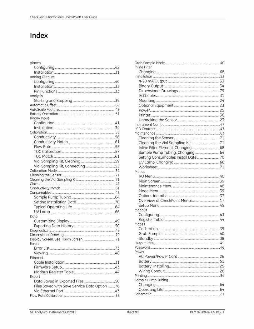
CheckPoint Pharma and CheckPointe User Guide
GE Analytical Instruments ©2012 89 of 90 DLM 97200-02 EN Rev. A
Index
Alarms
Configuring ........................................................................... 42 Installation ............................................................................. 31
Analog Outputs
Configuring ........................................................................... 40 Installation ............................................................................. 33 Pin Functions ........................................................................ 33
Analysis
Starting and Stopping ..................................................... 39 Automatic Offset .............................................................................. 62 AutoScale Feature ........................................................................... 49 Battery Operation ............................................................................ 51 Binary Input
Configuring ........................................................................... 41 Installation ............................................................................. 34
Calibration ........................................................................................... 55
Conductivity .......................................................................... 56 Conductivity Match........................................................... 61 Flow Rate ............................................................................... 55 TOC Calibration ................................................................... 57 TOC Match ............................................................................. 61 Vial Sampling Kit, Cleaning ........................................... 59 Vial Sampling Kit, Connecting ..................................... 52
Calibration Mode .............................................................................. 39 Cleaning the Sensor........................................................................ 71 Cleaning the Vial Sampling Kit ................................................... 71 Clock ...................................................................................................... 47 Conductivity Match ......................................................................... 61 Consumables ..................................................................................... 48
Sample Pump Tubing ...................................................... 64 Setting Installation Date ................................................ 70 Typical Operating LIfe ..................................................... 64 UV Lamp ................................................................................. 66
Data
Customizing Display ......................................................... 49 Exporting Data History ................................................... 50
Diagnostics ......................................................................................... 48 Dimensional Drawings .................................................................. 79 Display Screen. See Touch Screen. .......................................... 71 Errors
Error List ................................................................................. 73 Viewing .................................................................................... 48
Ethernet
Cable Installation ............................................................... 31 Firmware Setup .................................................................. 43 Modbus Register Table ................................................... 44
Export
Data Saved in Exported Files ....................................... 50 Files Saved with Save Service Data Option ......... 76 Via Ethernet Port ................................................................ 43
Flow Rate Calibration ..................................................................... 55
Grab Sample Mode ......................................................................... 40 Inline Filter
Changing ............................................................................... 68 Installation .......................................................................................... 23
4-20 mA Output ................................................................. 33 Binary Output ...................................................................... 34 Dimensional Drawings ................................................... 79 I/O Cables .............................................................................. 31 Mounting ................................................................................ 24 Optional Equipment ......................................................... 23 Power ....................................................................................... 25 Printer ...................................................................................... 36 Unpacking the Sensor..................................................... 23
Instrument Name ............................................................................ 47 LCD Contrast ...................................................................................... 47 Maintenance ...................................................................................... 63
Cleaning the Sensor ......................................................... 71 Cleaning the Vial Sampling Kit ................................... 71 Inline Filter Element, Changing .................................. 68 Sample Pump Tubing, Changing ............................... 64 Setting Consumables Install Date ............................ 70 UV Lamp, Changing ......................................................... 66 Worksheet ............................................................................. 71
Menus
I/O Menu................................................................................. 40 Main Screen .......................................................................... 39 Maintenance Menu .......................................................... 48 Mode Menu ........................................................................... 39 Options (details) .................................................................. 37 Overview of CheckPoint Menus ................................. 17 Setup Menu .......................................................................... 45
Modbus
Configuring ........................................................................... 43 Register Table ...................................................................... 44
Modes
Calibration ............................................................................. 39 Grab Sample ........................................................................ 40 Standby .................................................................................. 38
Output Rate ........................................................................................ 45 Password ............................................................................................. 46 Power
AC Power/Power Cord .................................................... 26 Battery ..................................................................................... 51 Battery, Installing............................................................... 25 Wiring Conduit .................................................................... 26
Printing ................................................................................................. 54 Sample Pump Tubing
Changing ............................................................................... 64 Operating Life ...................................................................... 64
Schematic ........................................................................................... 21

CheckPoint Pharma and CheckPointe User Guide
GE Analytical Instruments ©2012 90 of 90 DLM 97200-02 EN Rev. A
Standby Mode ................................................................................... 38 Storing the Sensor ........................................................................... 54 System Protocols ............................................................................. 55 System Specifications .................................................................... 19 TOC Autozero ..................................................................................... 59
Manual .................................................................................... 60 Scheduling ............................................................................. 60
TOC Deviation Finder ..................................................................... 50 TOC Match........................................................................................... 61 Touch Screen:cleaning .................................................................. 71 Touchscreen Buttons
Navigation Keys ................................................................. 38
Overview ................................................................................ 37 Troubleshooting ............................................................................... 73
Basic Steps ............................................................................ 75 Reviewing Error List .......................................................... 73
Units of Measure .............................................................................. 47 UV Lamp
Changing ............................................................................... 66 Operating Life ...................................................................... 64
Vial Sampling Kit
Cleaning ................................................................................. 59 Connecting............................................................................ 52