operation and maintenance manual - yellow...
TRANSCRIPT
RecoverX™ Oil-Filled Hermetic Refrigerant Recovery System
Operation and Maintenance Manual
1) Know your equipment. Read and understand the operation manual and the labels affixed to the unit. Learn its applications and limitations, as well as the specific potential hazards of your equipment.
2) Use the correct hoses. Use only hoses designed for handling of refrigerants. The hoses should be the minimum length required to do the job and be equipped with a shut-off device (such as the compact ball valve) located within 12 inches of the end to reduce the likelihood of refrigerant leaks to the atmosphere. There is a YELLOW JACKET hose for almost every type of refrigerant. See your distributor for more information.
3) Ground all equipment. Plug this device into properly grounded receptacle with an appropriate plug.
4) Do not pressure test with com-pressed air. Some mixtures of air and refrigerant have been shown to be combustible at elevated pressures.
5) Avoid dangerous environments. Use with sufficient ventilation to keep operator exposure to a minimum.
Always perform recovery in well ventilated areas. Use this equipment only in locations with mechanical ventilation, providing at least four air changes per hour, or the equipment should be placed 18” above the floor.
This equipment should not be used near open containers of gasoline or any other flammable liquid. Do not allow refrigerants to contact open flame. Refrigerant decomposition in flame results in phosgene gas. Breathing phosgene gas can be fatal.
6) Always wear safety goggles and gloves. Personal protective equip-ment should be worn to protect operator from frostbite.
7) Use caution when connecting or disconnecting. Improper usage may result in refrigerant burns (frostbite).
General Safety Instructions
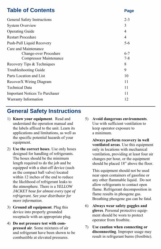
Table of Contents Page
General Safety Instructions 2-3
System Overview 3
Operating Guide 4
Restart Procedure 4
Push-Pull Liquid Recovery 5-6
Care and Maintenance Change-over Procedure 6-7 Compressor Maintenance 7-8
Recovery Tips & Techniques 8
Troubleshooting Guide 9
Parts Location and List 10
RecoverX Wiring Diagram 11
Technical Data 11
Important Notices To Purchaser 11
Warranty Information 12
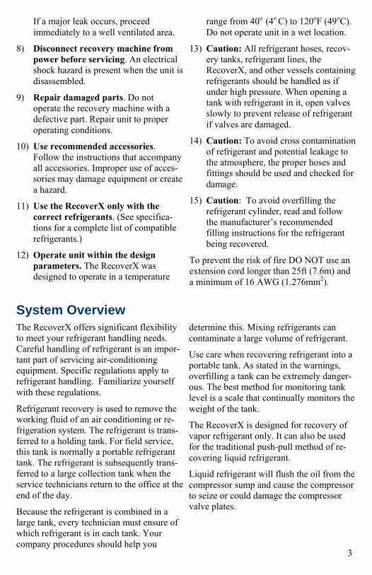
If a major leak occurs, proceed immediately to a well ventilated area.
8) Disconnect recovery machine from power before servicing. An electrical shock hazard is present when the unit is disassembled.
9) Repair damaged parts. Do not operate the recovery machine with a defective part. Repair unit to proper operating conditions.
10) Use recommended accessories. Follow the instructions that accompany all accessories. Improper use of acces-sories may damage equipment or create a hazard.
11) Use the RecoverX only with the correct refrigerants. (See specifica-tions for a complete list of compatible refrigerants.)
12) Operate unit within the design parameters. The RecoverX was designed to operate in a temperature
range from 40o (4o C) to 120oF (49oC). Do not operate unit in a wet location.
13) Caution: All refrigerant hoses, recov-ery tanks, refrigerant lines, the RecoverX, and other vessels containing refrigerants should be handled as if under high pressure. When opening a tank with refrigerant in it, open valves slowly to prevent release of refrigerant if valves are damaged.
14) Caution: To avoid cross contamination of refrigerant and potential leakage to the atmosphere, the proper hoses and fittings should be used and checked for damage.
15) Caution: To avoid overfilling the refrigerant cylinder, read and follow the manufacturer’s recommended filling instructions for the refrigerant being recovered.
To prevent the risk of fire DO NOT use an extension cord longer than 25ft (7.6m) and a minimum of 16 AWG (1.276mm2).
System Overview The RecoverX offers significant flexibility to meet your refrigerant handling needs. Careful handling of refrigerant is an impor-tant part of servicing air-conditioning equipment. Specific regulations apply to refrigerant handling. Familiarize yourself with these regulations.
Refrigerant recovery is used to remove the working fluid of an air conditioning or re-frigeration system. The refrigerant is trans-ferred to a holding tank. For field service, this tank is normally a portable refrigerant tank. The refrigerant is subsequently trans-ferred to a large collection tank when the service technicians return to the office at the end of the day.
Because the refrigerant is combined in a large tank, every technician must ensure of which refrigerant is in each tank. Your company procedures should help you
determine this. Mixing refrigerants can contaminate a large volume of refrigerant.
Use care when recovering refrigerant into a portable tank. As stated in the warnings, overfilling a tank can be extremely danger-ous. The best method for monitoring tank level is a scale that continually monitors the weight of the tank.
The RecoverX is designed for recovery of vapor refrigerant only. It can also be used for the traditional push-pull method of re-covering liquid refrigerant.
Liquid refrigerant will flush the oil from the compressor sump and cause the compressor to seize or could damage the compressor valve plates.
3
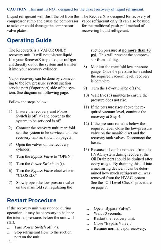
The RecoverX is a VAPOR ONLY recovery unit. It will not tolerate liquid. Use your RecoverX to pull vapor refriger-ant directly out of the system and transfer it into your recovery cylinder. Vapor recovery can be done by connect-ing to the low pressure system suction service port (Vapor port) side of the sys-tem. See diagram on following page. Follow the steps below: 1) Ensure the recovery unit Power
Switch is off (○) and power to the system to be serviced is off.
2) Connect the recovery unit, manifold set, the system to be serviced, and the recovery tank as shown on page 5.
3) Open the valves on the recovery cylinder.
4) Turn the Bypass Valve to “OPEN.”
5) Turn the Power Switch on (׀ ).
6) Turn the Bypass Valve clockwise to “CLOSED.”
7) Slowly open the low pressure valve on the manifold set, regulating the
suction pressure at no more than 40 psi. This will prevent the compres-sor from stalling.
8) Monitor the manifold low-pressure gauge. Once the pressure has reached the required vacuum level, recovery is complete.
9) Turn the Power Switch off (○).
10) Wait five (5) minutes to ensure the pressure does not rise.
11) If the pressure rises above the re-quired vacuum level, continue the recovery at Step 4.
12) If the pressure remains below the required level, close the low-pressure valve on the manifold set and the recovery tank valves. Disconnect the hoses.
13) Because oil can be removed from the HVAC system during recovery, the Oil Drain port should be drained after every usage. By draining this oil into a measuring device, it can be deter-mined how much refrigerant oil was removed from the HVAC system. See the “Oil Level Check” procedure on page 7.
Operating Guide
Restart Procedure
Liquid refrigerant will flush the oil from the compressor sump and cause the compressor to seize or could damage the compressor valve plates.
The RecoverX is designed for recovery of vapor refrigerant only. It can also be used for the traditional push-pull method of recovering liquid refrigerant.
CAUTION: This unit IS NOT designed for the direct recovery of liquid refrigerant.
If the recovery unit was stopped during operation, it may be necessary to balance the internal pressures before the unit will start. • Turn Power Switch off (○). • Stop refrigerant flow to the suction
port on the unit.
• Open “Bypass Valve”. • Wait 30 seconds. • Restart the recovery unit. • Close “Bypass Valve”. • Resume normal vapor recovery.
4
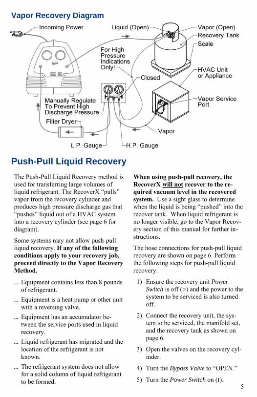
Vapor Recovery Diagram
Push-Pull Liquid Recovery
The Push-Pull Liquid Recovery method is used for transferring large volumes of liquid refrigerant. The RecoverX “pulls” vapor from the recovery cylinder and produces high pressure discharge gas that “pushes” liquid out of a HVAC system into a recovery cylinder (see page 6 for diagram).
Some systems may not allow push-pull liquid recovery. If any of the following conditions apply to your recovery job, proceed directly to the Vapor Recovery Method.
• Equipment contains less than 8 pounds of refrigerant.
• Equipment is a heat pump or other unit with a reversing valve.
• Equipment has an accumulator be-tween the service ports used in liquid recovery.
• Liquid refrigerant has migrated and the location of the refrigerant is not known.
• The refrigerant system does not allow for a solid column of liquid refrigerant to be formed.
When using push-pull recovery, the RecoverX will not recover to the re-quired vacuum level in the recovered system. Use a sight glass to determine when the liquid is being “pushed” into the recover tank. When liquid refrigerant is no longer visible, go to the Vapor Recov-ery section of this manual for further in-structions.
The hose connections for push-pull liquid recovery are shown on page 6. Perform the following steps for push-pull liquid recovery:
1) Ensure the recovery unit Power Switch is off (○) and the power to the system to be serviced is also turned off.
2) Connect the recovery unit, the sys-tem to be serviced, the manifold set, and the recovery tank as shown on page 6.
3) Open the valves on the recovery cyl-inder.
4) Turn the Bypass Valve to “OPEN.”
5) Turn the Power Switch on (׀ ). 5

6) Turn the Bypass Valve to “CLOSED.”
7) Slowly open the low pressure valve on the manifold set. Manually regu-late the suction pressure at no more than 40 psi. This will prevent com-pressor from stalling.
8) Monitor the sight glass. When there is no longer significant liquid refrigerant passing through the sight glass, push-pull liquid recovery is complete.
9) Close the low pressure gage on the manifold set.
10) Turn the Power Switch off (○).
11) Close the valves on the recovery tank.
Proceed to the Vapor Recovery procedure to remove the remainder of the refrigerant and to evacuate the system to the required vacuum level.
Push-Pull Liquid Recovery, cont.
Push-Pull Diagram
Change-over Procedure Different types of refrigerant and refrig-erant oil should not be mixed in the re-covery unit. If recovering a different type of refrigerant, the recovery unit must be completely evacuated. Follow these steps to pump down the system for use with another refrigerant.
1) Place a cap on the suction port of the unit and turn the Bypass Valve to “CLOSED.” Turn the unit on and run it for two minutes.
2) Apply 10-30 psig pressure of inert gas such as nitrogen to the suction port.
3) Turn the Bypass Valve to “OPEN.”
4) Turn the Power Switch on (׀ ).
5) Turn the Bypass Valve to “CLOSED” and run for 15 seconds.
Note: The inert gas will enter the re-covery cylinder. This small amount of non-condensable gas will be removed during the reclamation process.
6) Turn the Power Switch off (○).
7) Close all valves and remove the hose from the recovery tank.
8) Connect the hose to a vacuum pump. 6
9) Run the vacuum pump for at least 10 minutes to remove the remaining refrigerant and non-condensable gas.
10) Check the compressor oil for con-tamination and proper level. Add or change oil if needed.
11) Unit is ready for use with another refrigerant.
Change-over Procedure, cont.
Compressor Maintenance
OIL LEVEL CHECK
This unit has been factory charged with 7 ounces POE oil. Check the compressor oil before and after each use. An overfilled oil sump can overload the compressor. Too little oil can cause the compressor to seize.
CAUTION: The recovery unit is under high pressure. Do not remove the cap on the compressor oil port without following this complete procedure!
To check the oil level: 1) Place a cap on the suction port of the
unit and close the bypass valve. Turn the unit on and run it for two minutes.
2) Slowly remove the brass cap from the compressor oil port. If pressure is pre-sent, continue running the unit until there is no pressure on the port.
3) Place a small catch device under the open drain port or attach a hose and direct it toward a catch device.
4) With the machine on a flat surface, uncap the suction port. Excess oil will
come out of the oil drain port. Low pressure compressed air can be applied to the suction port to assist the draining process.
5) Allow excess oil to drain into the catch device.
6) If no oil comes from the drain, add one ounce of refrigerant oil to the compres-sor. Check the oil level. Once a small amount of oil comes from the drain, the oil level is correct. If not, repeat this step.
7) Replace the brass cap on the oil drain port.
8) Ensure the unit is working properly before using it to recover refrigerant.
COMPLETE OIL CHANGE
The compressor oil should be changed at least every six (6) months (more often if unit is used frequently). The oil may need to be changed after servicing a system that had a compressor burn out or high contamina-tion levels.
To change the compressor oil: 1) Place a cap on the suction port of the
unit. Turn the unit on and run it for two minutes.
2) Remove the brass cap from the com-pressor oil port
3) Place a catch device under the open drain port or attach a hose and direct it toward a catch device.
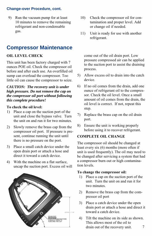
4) Tilt the machine on its side as shown. This allows most of the oil to drain out of the recovery unit. 7

Here are a few time saving techniques to help you on your next job:
1) Use the shortest hoses possible and when possible avoid hoses with schrader depressors. This will help assure the fastest and quickest recovery possible.
2) Know what kind of refrigerant you are going to recover and the amount. You need to know what kind to avoid contamination. More importantly you need to know how much refrigerant you plan to recover. This will help you avoid overfilling your recovery cylinder which can have disastrous results.
3) If you plan on recovering large amounts of refrigerant (20lbs or more) it would be a good idea to use
the push-pull method. Note: This process requires you to switch hoses to finish recovering the remaining vapor. See the “Push– Pull Liquid Recovery” section of this manual.
4) Protect your RecoverX by using an in-line filter drier. Failure to use a suction filter drier can cause damage to your compressor.
5) Recovery machines are not vacuum pumps. For proper evacuation use your YELLOW JACKET vacuum pump. To speed up the evacuation process try using your TITAN™ manifold and core removal tool (P/N 18975). For more information contact your local YELLOW JACKET wholesaler.
8
Recovery Tips and Techniques
RecoverX Front View
5) Uncap the suction port. The compres-sor oil will come out of the drain port. Low pressure compressed air can be applied to the suction port to assist the draining process.
6) Refill the oil sump with 7 ounces of POE refrigerant oil.
7) Return the machine to a flat position and check the oil level as described previously.
Compressor Maintenance, cont.

Troubleshooting Guide Problem Possible Cause Solution
Compressor will not start
• Power cord not plugged in • Plug in to energized 110V receptacle
• 110V receptacle not energized • Check 110V receptacle for power
• High Pressure Switch not reset • Reduce discharge pressure and reset. • If switch will not reset, check dis-
charge for restrictions or schrader core not fully depressed.
• Circuit Breaker is tripped • Reset circuit breaker
• Defective system switch • Replace switch
Unit starts but stops after a short period
• Restriction on the discharge port • Open valve on recovery tank • Ensure schrader core on discharge
port is fully depressed • Check for other restrictions
• High differential pressure across compressor
• Turn Bypass Valve to “OPEN.”
• Liquid refrigerant present in the sump of the compressor
• Remove liquid refrigerant from sump of compressor.
• Compressor oil level is too low or too high.
• Check oil level and add or drain if necessary
Unit will not perform liquid push-pull recovery
• System to be serviced does not allow liquid recovery
• Use Vapor Recovery method
Compressor starts but trips the circuit breaker upon start up
UL Certified Rates to ARI Standard 740-98
Other Refrigerants: YELLOW JACKET RecoverX is approved for use with the following refrigerants which has not been certified for a particular recovery rate. R-12, R-134a, R-401C, R-406A, R-500, R-401A, R-409A, R-401B, R-412A, R-411A, R
-407D, R-22, R-411B, R-502, R-407C, R-402B, R-408A, R-509.
R12 R134a R22 R500 R502
Vapor lbs./min .24 .20 .29 .24 .24
Liquid lbs./min N/A N/A N/A N/A N/A
Push-Pull lbs./min 10.4 9.3 8.8 9.6 7.6
Vacuum Level 15 in. Hg 15 in. Hg 15 in. Hg 15 in. Hg 15 in. Hg
9

10
Item # Part# Description Item # Part# Description
1 95444 Case, Front 9 95178 4" Fan Motor Assembly
2 95445 Case, Rear 10 95460 Bypass Valve
3 95446 Case Half (both halves) 11 95463 Compressor Inlet Assembly
4 95447 Case, Cord Wrap 12 95464 Discharge Hose Assembly
5 93394 1/4" Flare Cap & Strap 13 95473 Compressor Discharge Assembly
6 95461 High Pressure Gauge Panel Mount
14 95423 High Pressure Switch
7 95462 Low Pressure Gauge Panel Mount
15 95163 Check Valve (2) 1/4" mfl x 1/4" mfl
8 95178 Condenser Coil 16 95472 Service Compressor
N/A 95158 Start Relay N/A 95465 Operation Manual
Parts Location and List
95700 Parts

Compressor: 1/6 HP hermetically sealed reciprocating
Power Source: 115Vac 60 Hz
Amperage: Run Load Amps: 1.5 Full Load Amps: 2.0 Locked Rotor Amps: 8.0 Size: Height: 12.5" Width: 12.4" Depth: 19.3" Weight: 29 lbs.
Important Notice To Purchaser
Check for damage immediately. Prior to shipment, all YELLOW JACKET RecoverX Recovery Systems are completely tested and inspected to assure compliance with Ritchie Engineering factory specifications. If the recovery system carton is damaged, check contents immediately. Note damage on shipper’s Bill of Lading and have shipper sign statement. Notify the carrier immediately of the damage to arrange inspection of the recovery sys-tem and packaging.
The CARRIER ALONE is responsible for handling and settling your claim. Ritchie Engineering will cooperate in assessing damage if the recovery system is returned to the factory prepaid. Carton contents include: • RecoverX Series Recovery System • Owner’s manual • Warranty registration card To validate warranty, mail registration card within 10 days.
11
Wiring Diagrams
Technical Data
Warranty Information
Ritchie Engineering guarantees YELLOW JACKET products to be free of defective material and workmanship which could affect the life of the product when used for the purpose for which it was designed. Warranty does not cover items that have been altered, abused or returned solely in need of field service maintenance. If found defective, we will either replace or repair at our option products returned within 15 months of factory shipment. All returns must be return freight prepaid.
The following steps must be taken by you or your wholesaler before the unit can be returned: 1. Call our technical service personnel
at (800)769-8370 to see if the prob-lem can be resolved over the phone.
2. Obtain an RMA number from Ritchie Engineering.
3. Fax a copy of the original invoice to (952)943-1140.
If at any time after the warranty period you have problems with your YELLOW JACKET recovery unit, call our technical service department for help in selecting the correct replacement parts, or arrange for us to make the repair at a reasonable cost.
Ritchie Engineering YELLOW JACKET Products Division 10950 Hampshire Avenue South Bloomington, MN 55438 USA Phone: 952-943-1333 Phone: 800-769-8370 Fax: 952-943-1605 e-mail: [email protected] Web Site: www.yellowjacket.com
Printed in U.S.A. Part #151053_C