operation and maintenance of hydraulic machinery: a ... · operation and maintenance of hydraulic...
TRANSCRIPT
l 1
J
PAP-738
Operation and Maintenance of Hydraulic Machinery: A Summary Report
by
K. Warren Frizell
September 30, 1996
WATER RESOURCES RESEARCH LABORATORY OFFICIAL FILE COPY
]
Operation and Maintenance of Hydraulic Machinery: A Summary Report
Prepared for Director of Research, Bureau of Reclamation
by K. Warren Frizell
September 30, 1996

[

Table of Contents
Introduction ....................................... o • • • • • • • • • • • • • • • • • • • • • • • • • • • • 1
Resea.rch Topics ............ ~ . . . . . . . . . . . . . . . . . . . . . . . . . . . . . . . . . . . . . . . . . . . . . . . . . . . . 2 Cavitation Detection in Hydraulic Turbines . . . . . . . . . . . . . . . . . . . . . . . . . . . . . . . . . . . . . . . . . 2
Background . . . . . . . . . . . . . . . . . . . . . . . . . . . . . . . . . . . . . . . . . . . . . . . . . . . . . . . . . . . . . . 2 Approach ................................................................ 3 Experiments . . . . . . . . . . . . . . . . . . . . . . . . . . . . . . . . . . . . . . . . . . . . . . . . . . . . . . . . . . . . . . 5
Laboratory Model Wicket Gate . . . . . . . . . . . . . . . . . . . . . . . . . . . . . . . . . . . . . . . . . . . 5 Model Turbine Investigations . . . . . . . . . . . . . . . . . . . . . . . . . . . . . . . . . . . . . . . . . . . . . 6 Flatiron Powerplant Wicket Gate Studies . . . . . . . . . . . . . . . . . . . . . . . . . . . . . . . . . . . . 7 Cavitation Detection at J.F. Carr Powerhouse . . . . . . . . . . . . . . . . . . . . . . . . . . . . . . . . 7 Cavitation Detection at Shasta Powerplant. . . . . . . . . . . . . . . . . . . . . . . . . . . . . . . . . . . . 8
Conclusions . . . . . . . . . . . . . . . . . . . . . . . . . . . . . . . . . . . . . . . . . . . . . . . . . . . . . . . . . . . . . . 9 Environmentally-Safe Wicket Gate Lubricants . . . . . . . . . . . . . . . . . . . . . . . . . . . . . . . . . . . . . 10
Background . . . . . . . . . . . . . . . . . . . . . . . . . . . . . . . . . . . . . . . . . . . . . . . . . . . . . . . . . . . . . 10 Mechanical Test Setup and Procedure . . . . . . . . . . . . . . . . . . . . . . . . . . . . . . . . . . . . . . . . . 10 Testing ................................................................. 11 Conclusions . . . . . . . . . . . . . . . . . . . . . . . . . . . . . . . . . . . . . . . . . . . . . . . . . . . . . . . . . . . . . 11
Draft Tube Surge Detection .................................................... 12 Approach .............................................................. : 12 Conclusions . . . . . . . . . . . . . . . . . . . . . . . . . . . . . . . . . . . . . . . . . . . . . . . . . . . . . . . . . . . . . 13
Turbine Aeration to Enhance Downstream Water Quality . . . . . . . . . . . . . . . . . . . . . . . . . . . . 14 Background ....................... ; . . . . . . . . . . . . . . . . . . . . . . . . . . . . . . . . . . . . . 14 Approach . . . . . . . . . . . . . . . . . . . . . . . . . . . . . . . . . . . . . . . . . . . . . . . . . . . . . . . . . . . . . . . 14 Conclusions .............................................................. 15
Conclusions . . . . . . . . . . . . . . . . . . . . . . . . . . . . . . . . . . . . . . . . . . . . . . . . . . . . . . . . . . . . . . . . . . . 16
Related Publications . . . . . . . . . . . . . . . . . . . . . . . . . . . . . . . . . . . . . . . . . . . . . . . . . . . . . . . . . . . . 17
Introduction This report summarizes work which was accomplished under Reclamation's WATER Program, project PS006, "Operation and Maintenance of Hydraulic Machinery." Funding was discontinued in FY96 with the exception of about 15 SD in order to close out on-going work and provide a summary report. This report will summarize findings of major topics of the research program and give references to additional publications. The topics which will be covered include cavitation detection in hydraulic turbines, environmentally-safe wicket gate lubricants, draft tube surge detection, and turbine aeration to enhance downstream water quality. Each major topic will be addressed individually due to their diverse nature.
Operation and Maintenance of Hydraulic Machinery: A Sununary Report
J
Research Topics
Cav/lallon Deleollon In Hydraulic Turbines The detection of cavitation in hydraulic turbines is desirable in order to better define maintenance periods where turbine runners need to be repaired. The trend in powerplant maintenance is toward condition-based rather than the more traditional time-based scheduling. For this reason, talcing a unit out of service in order to perform weld repairs on the runner should be based on deterioration of performance due to damage on the runner, not simply on the number of hours of operation. Cavitation damage to hydraulic turbine runners has long been an issue for both operations and maintenance. Damage can be reduced due to design enhancements and operational settings, however, the majority of Reclamation powerplants feature aging equipment. In addition, many turbinegenerator units have been uprated, occasionally pushing increased discharges (i.e., higher velocities) through the existing water passages which cause problems where previously there were none.
The goal of the current research is to come up with an affordable sensor/system which can effectively detect "damaging" cavitation in a hydraulic turbine. This sensor/system could then be integrated into a machine condition monitoring scheme whereby maintenance and repairs are based on the condition of the machine. In addition, the sensor/system should be general in nature, not requiring site-specific calibration in order to perform. Most systems will be used on Francis-type turbines but there are occasions where the system could be installed on an impulse turbine or even axial-flow units (such as the new Kaplan units at the Minidoka Replacement Powerplant).
Baolcground
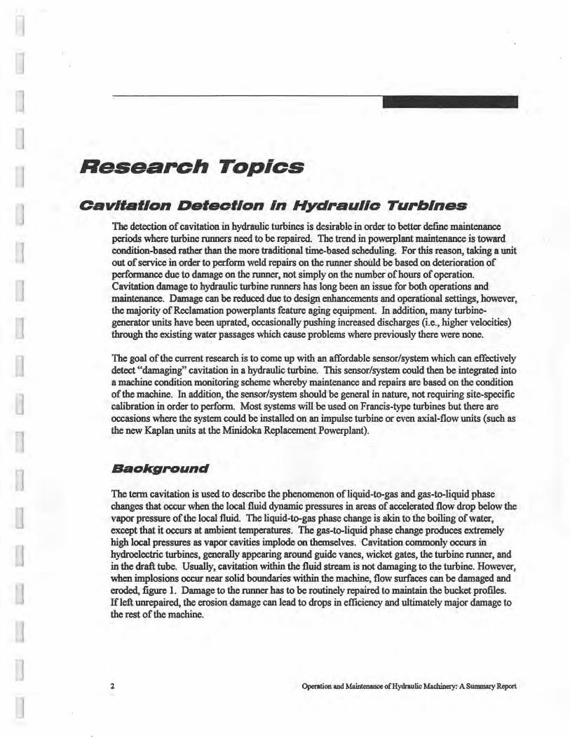
The term cavitation is used to describe the phenomenon of liquid-to-gas and gas-to-liquid phase changes that occur when the local fluid dynamic pressures in areas of accelerated flow drop below the vapor pressure of the local fluid. The liquid-to-gas phase change is akin to the boiling of water, except that it occurs at ambient temperatures. The gas-to-liquid phase change produces extremely high local pressures as vapor cavities implode on themselves. Cavitation commonly occurs in hydroelectric turbines, generally appearing around guide vanes, wicket gates, the turbine runner, and in the draft tube. Usually, cavitation within the fluid stream is not damaging to the turbine. However, when implosions occur near solid boundaries within the machine, flow surfaces can be damaged and eroded, figure 1. Damage to the runner has to be routinely repaired to maintain the bucket profiles. If left unrepaired, the erosion damage can lead to drops in efficiency and ultimately major damage to the rest of the machine.
2 Operation and Maintenance of Hydraulic Machinery: A Sununary Report
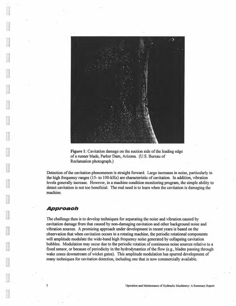
Figure 1: Cavitation damage on the suction side of the leading edge of a runner blade, Parker Dam, Arizona. (U.S. Bureau of Reclamation photograph.)
Detection of the cavitation phenomenon is straight foIWard. Large increases in noise, particularly in the high frequency ranges (15- to 100-kHz) are characteristic of cavitation. In addition, vibration levels generally increase. However, in a machine condition monitoring program, the simple ability to detect cavitation is not too beneficial. The real need is to learn when the cavitation is damaging the machine.
Approaoh
The challenge then is to develop techniques for separating the noise and vibration caused by cavitation damage from that caused by non-damaging cavitation and other background noise and vibration sources. A promising approach under development in recent years is based on the observation that when cavitation occurs in a rotating machine, the periodic rotational components will amplitude modulate the wide-band high frequency noise generated by collapsing cavitation bubbles. Modulation may occur due to the periodic rotation of continuous noise sources relative to a fixed sensor, or because of periodicity in the hydrodynamics of the flow (e.g., blades passing through wake zones downstream of wicket gates). This amplitude modulation has spurred development of many techniques for cavitation detection, including one that is now commercially available.
3 Operation and Maintenance of Hydraulic Machinery: A Summary Report
Amplitude modulated-based, cavitation detection techniques identify cavitation as a hidden periodicity within an isolated band of the high frequency noise floor. Typically, the raw signal is bandpass :filtered for the desired high frequency band and the discovery of the hidden periodicity is accomplished through demodulation of the bandpassed signal using the principal of envelope detection. Most of the cavitation detection techniques use half- or full-wave rectification spectral analysis to perform wide-band demodulation on the raw measurement signals. The rectification can be accomplished either by hardware or software methods. Generally, frequencies of interest are the unit's rotational speed and its harmonics, particularly the blade passing frequency of the turbine runner.
In a machine condition monitoring system, a fixed sensor is desirable from a practicality standpoint. Placement of the sensor is very important. Broadband acoustic emission sensors or high frequency accelerometers (amplified analog output proportional to stress wave activity or vibration), mounted on the wicket gate assembly or the turbine guide bearing assembly have successfully detected "damaging" cavitation. Acoustic emission sensors mounted on the shell of the draft tube have produced similar results. Either of these techniques has deficiencies, particularly related to universal application on different machines. Again, the cavitation phenomenon can be detected easily. However, determining the severity of the damage that may be occurring on the runner by either of these methods is difficult. Calibrating the system with data about known cavitation zones, duration of exposure, and extent of damage from maintenance data may be possible. However, geometric differences between similar machine types or totally different machine types (i.e., Francis vs. Kaplan) significantly affect amplitudes produced by these fixed sensor demodulation techniques and may require machine specific calibrations.
To make direct measurement of material damage, the use of acoustic emissions sensors has beco~e the method of choice in the non-destructive testing {NDT) field. In order to pick up the typical inplane stress waves which are characteristic of microcracks, the sensor should be attached directly to the piece being damaged. Acoustic emissions are severely attenuated by most types of interfaces (e.g., bearings), but particularly by water. Thus, a fixed sensor on the wicket gates, draft tube, or bearing housing may not effectively indicate when damage is occurring on the rotating runner. A two-sensor approach may be desirable, using a fixed sensor to identify individual buckets where cavitation is present, along with a rotating sensor (mounted on the shaft as near the runner as possible) that indicates the intensity of the cavitation damage.
One limitation of the half- or full-wave rectification demodulation technique is that it is affected by discrete components (machine noise) that are present and so bandpass :filtering has to take place prior to demodulation. Otherwise, these discrete frequencies will generate peaks in the demodulated signal as well, erroneously showing hidden periodicity.
A new technique that overcomes this limitation has been used successfully to identify cavitation in high speed turbo pumps. This technique uses a recently discovered unique coherent phase relationship within the wide-band noise floor of a cavitation-generated signal. The combination of a Phase-Only filter and an Amplitude-Medium filter removes discrete components and allows for detection of hidden periodicity generated by the coherent phase components in the wide-band noise floor and a non-normalized spectral function detects the strength of the cavitation generated wideband modulated signals. Another noticeable advantage is that no high-pass :filtering or high frequency analysis is required since the low frequency noise floor contains the wide-band modulated coherent phase information.
4 Operation and Maintenance of Hydraulic Machinery: A Summary Report
While this new technique solves some problems associated with full-wave rectification spectral analysis, questions still exist as to the wide application of either of these techniques in a machine condition monitoring system due to the methods used to identify cavitation severity and relate it to the damage occurring. A hybrid system incorporating features of each technique along with a twosensor approach seems to allow for the most generaliz.ed application among hydroelectric turbines.
Experiments
Several different experiments have taken place over the past two years in the attempt to develop a cavitation detection sensor for a machine condition monitoring system. These experiments included working with a laboratory model wicket gate, a model turbine, and several prototype turbines. Each experiment will be briefly discussed along with important findings.
Laboratory Model Wicket Gate
We used a scale model of a single wicket gate to further investigate the amplitude modulation of wide-band high frequency cavitation noise. By adjusting the angle of attack of the wicket gate, we can generate flow regimes of I) no cavitation, 2) leading edge cavitation with a closed vapor cavity, and 3) supercavitation.
Tests were carried out using an undamped AE sensor which was attached to the shaft of the wicket gate just above the intermediate bushing. A B&K Model 2635 charge amplifier was used to condition the signal of the AE sensor. In addition, a two-channel analog filter, a full-waverectification circuit, and a two-channel spectrum analyzer were used in the experiments. This experiment, while physically different from a rotating machinery arrangement, showed that the wideband high-frequency noise floor generated by cavitation is amplitude modulated at a frequency which is characteristic of the closed cavity which forms on the leading edge of the wicket gate. This cavity forms and grows in length until conditions cause it to separate. Once the cavity opens up the modulated noise disappears from the spectrum, even though significant cavitation is occurring within the flow stream.
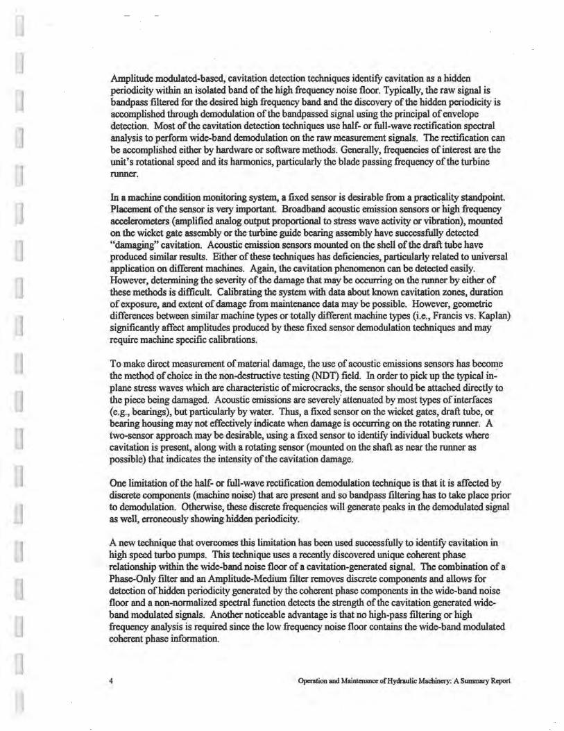
Significant noise in the low frequency spectrum is picked up by the AE sensor as the closed cavity "sings" a relatively pure tone (single frequency). The high-frequency cavitation noise is amplitude modulated at this same frequency. This data agrees well with other researchers work on attached cavities on hydrofoils. Figure 2 shows a comparison of data from the raw signal and the bandpassfiltered signal both before and after demodulation.
The demodulated signal magnitudes were compared for several sensor locations. Decay in magnitude is noticed as the placement becomes more decoupled from the wicket gate itself.
s Operation and Maintenance of Hydraulic Machinery: A Summary Report
-40 ------- ------------~~~---~
----I
~ ~ .50
! J ~ ~-><-1,--A-+-+---I-
.ao~---~-~---~-~-~-~-~-~ 0 500 1000 1500 2000
Frequency (Hz)
Figure 2: Wicket gate model with attached vapor cavity present.
Model Turbine Investigations
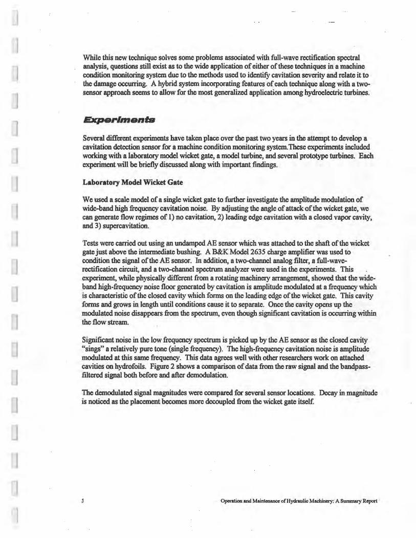
Reclamation and Colorado State University have cooperated on a number of tests involving cavitation detection using CSU's model turbine facility. The model is a 1:40.33 scale model of the 700 MW units at Grand Coulee Third Powerplant. The model turbine was originally located at th.e Estes Powerplant but was decommissioned in 1985 by Reclamation. By the end of the summer of 1989, the turbine test stand had been moved and reassembled in CSU's Hydromachinery Laboratory.
Initial testing investigated acoustic emission transmission paths throughout·the model turbine. A Physical Acoustics Corporation 3000/Spartan system was used. A calibrated AE sensor configured as an exciter was attached to a bucket on the turbine runner. Another AE sensor was then used to move around various locations and sense the level of output from the exciter. These tests were performed in air with the model turbine draft tube removed. The strongest transmission point was found to be on the shaft just below the lower coupling flange. Although the shaft was sensitive below this coupling, no signal could be detected above the coupling. This location was also the least sensitive to extraneous machine noise.
Additional studies were conducted with the model in operation. An AE sensor was mounted at various fixed locations, including the head cover, stay-vane ring, wicket gate shaft and draft tube shell. The model was operated in a non-cavitating region and then the tailwater was lowered until visible cavitation was present on the runner. The band-passed demodulated spectral analysis yielded frequency peaks at the bucket passing frequency and many of its subharmonics. The magnitudes of the spectral peaks were very dependant on the sensor location. This location dependance points to large geometric effects present on the transmission paths of the high-frequency cavitation noise.
6 Operation and Maintenance of Hydraulic Machinery: A Summary Report
Flatiron Powerplant Wicket Gate Studies
Cavitation monitoring equipment was installed on Flatiron Units 1 and 2 in order to detect what operating conditions were responsible for observed cavitation damage on the wicket gates. Cavitation has damaged the new wicket gates near the leading edge, especially just downstream from the seating area.
An accelerometer, an acoustic emission sensor, and a commercially available "cavitation monitor'' were all installed on each of the units. The accelerometer and AE sensor were epoxied to the lower end of a wicket gate stem, accessible from the draft tube mandoor area. The Senaco Cavitation Monitor was clamped on an adjacent wicket gate stem. The accelerometer and AE sensor outputs were bandpass filtered with an analog filter, passing the 20-kHz to 100-kHz band into a full-wave rectifier and then into a spectrum analyzer. The Senaco sensor output is a DC voltage which is proportional to cavitation activity level.
Frequency spectra were collected over the entire operating range of the unit. The highest levels were noted at the speed-no-load condition. Demodulated spectra indicated similar results with a peak occurring at the bucket passing frequency (145 .6 Hz).
Data indicate that the cavitation activity seems to be the highest at very small wicket gate openings. This was verified by both the AE sensor and the Senaco Cavitation Monitor. In addition, when the AE sensor output was demodulated, it indicated cavitation on the runner buckets as well. , Runner cavitation disappeared as the unit was loaded, with no evidence of cavitation at full load ( 44 MW).
Upon inspection of the wicket gate damage, it appears to have been caused by an offset into the flow created by an inlaid steel seal bar which was not ground down to the wicket gate profile. At speecino-load, the wicket gate openings are very small, yielding high velocities passing over this seal area. Gate leakage could also be partially responsible for the damage during the period of time when one of the bypass valves was left in the open position. Grinding the seal bar down to the wicket gate profile should eliminate future damage.
Cavitation Detection at J.F. Carr Powerhouse
Unit No. 1 at J.F. Carr Powerhouse was instrumented using the AE sensor described previously. This unit is a Francis turbine rotating at 225 r/min. Tailwater conditions vary greatly from summer to winter. Our tests were conducted during the low tailwater period. These units experience recurring cavitation damage on the runners which has to be weld-repaired every 2 to 3 years. There are 17 buckets on the runner and 20 wicket gates. The AE sensor was epoxied to one of the wicket gate stems. The output was bandpass :filtered and demodulated using full-wave rectification. This signal was then analyzed for its frequency content.
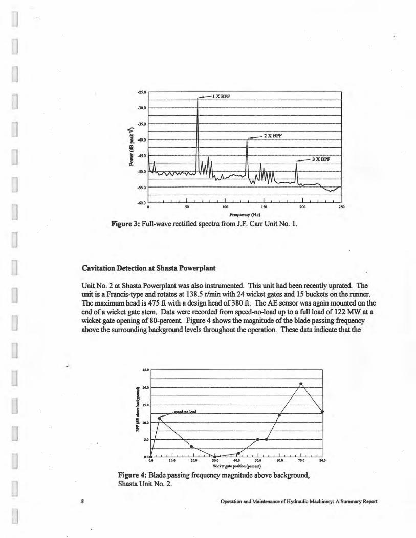
Data were gathered as the unit was loaded up to a full load of 86 MW (92-percent wicket gate). Figure 3 shows the full-wave rectified spectrum at a 77-percent wicket gate opening. This setting yielded the maximum amplitude in the bucket passing frequency - almost 25 dB above the background levels. Numerous other peaks, including harmonics and other predominate frequencies of the machine were also present.
7 Operation and Maintenance of Hydraulic Machinery: A Summary Report
]
-25.0 ~------------- ------ -~ --1XBPF
-30.0 ---- ... ---------- - -----------<
-35.0I-----·
'>' 1. --40.0 ·--tr------- -- 2XBPF ·----
! I------ ---H------1-------------+
J -45.0 !t--1------t·f-triH"
-50.o t"t"''Cl'Vvl'\N"~;:i'i,·tt1n---:-·--::--tt--:-fl11Tn
-ss.o
-a>.O ..____.___.___.___.._~~~..____.___.___.___.._~~~..____.___.___.___.._~~~..____. 0 50 JOO 150 200 250
Frequency (Hz)
Figure 3: Full-wave rectified spectra from J.F. Carr Unit No. 1.
Cavitation Detection at Shasta Powerplant
Unit No. 2 at Shasta Powerplant was also instrumented. This unit had been recently uprated. The unit is a Francis-type and rotates at 138.5 r/min with 24 wicket gates and 15 buckets on the runner. The maximum head is 4 75 ft with a design head of 3 80 ft. The AE sensor was again mounted on the end of a wicket gate stem. Data were recorded from speed-no-load up to a full load of 122 MW at a wicket gate opening of 80-percent. Figure 4 shows the magnitude of the blade passing frequency above the surrounding background levels throughout the operation. These data indicate that the
8
2'.0 ~-------------------,
~-------·-------- - ------
3.0
0.06-'-_,__i_L..L..J....J.._LL...i.....J:::.a-c:::c::c::I=.._J.....L-1.....,__,_.J....1.....1.......JL....1.....l....L...J.._L.J 0.0 10.0 20.0 30.0 -40.0 30.0 60.0 70.0
Wicket pla pooition {po,<ont)
Figure 4: Blade passing frequency magnitude above background, Shasta Unit No. 2.
IO.O
Operation and Maintenance ofHydraulic Machinery: A Summary Report

worst condition for cavitation is a wicket gate setting of about 70-percent Historical damage on these units has been minimal prior to the uprate. At the original rating, maximum load occurred at around a 60-percent wicket gate opening. New records must now be collected at these larger wicket gate openings where cavitation on the runner appears to be present.
Conolu•lon•
We have verified several methods to detect cavitation in hydraulic turbines. Some evidence exists that the point where the runner is being damaged also can be detected. We are still lacking information as to the magnitudes of the signal when the damage is occurring. Additional testing is required to identify the magnitude of the detection signal when damage to the runner is taking place. We may find that the geometric differences from unit to unit will not allow for the development of a geoerali2:ed damage detection level. We have submitted arid received funding through Reclamation's Enterprise Fund program to further develop a Machine Condition Monitor, of which one part is a cavitation damage detector.
9 Operation and Maintenance ofHydraulic Machinery: A Summary Report
Environ,nenla//y-Sal• Wicket Gale Lubricants
Baolcground
The testing of biodegradable, environmentally acceptable, waterproof greases was conducted to determine the long term viability for use in hydroelectric facilities. The greases presently used in these facilities for wicket gate bushings could contain lead, phosphorous, lithium, and benzene compounds which may ultimately be introduced into waterways and affect water quality, including effects on biological food chains. However, replacement of these lithium-based greases requires that the replacement greases meet water quality standards as well as providing mechanical properties that maximiu service life of the wicket gate bushings. Laboratory tests were conducted by the Water Resources Research Laboratory (WRRL) to determine if these environmentally safe lubricants will perform comparably to the current standards which provide for the bushings to last at least 40 years.
Meohanloal Test Setup and Prooedure
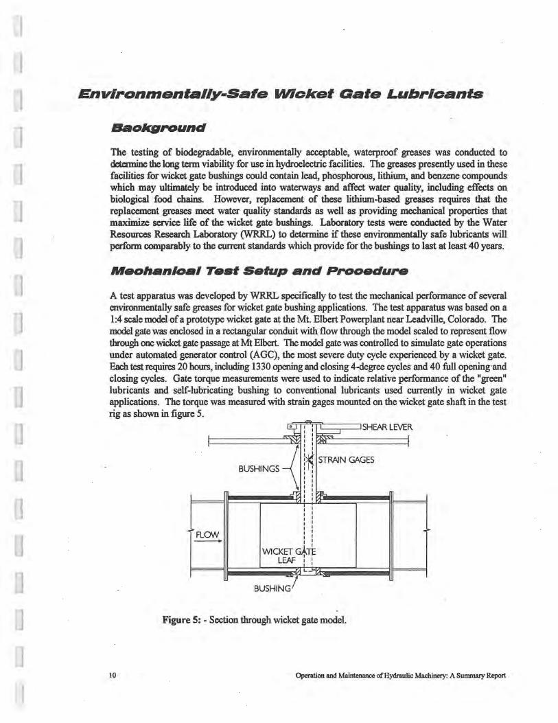
A test apparatus was developed by WRRL specifically to test the mechanical performance of several environmentally safe greases for wicket gate bushing applications. The test apparatus was based on a 1:4 scale model of a prototype wicket gate at the Mt. Elbert Powerplant near Leadville, Colorado. The model gate was enclosed in a rectangular conduit with flow through the model scaled to represent flow through one wicket gate passage at Mt Elbert. The model gate was controlled to simulate gate operations under automated generator control (AGC), the most severe duty cycle experienced by a wicket gate. Each test requires 20 hours, including 1330 opening and closing 4-degree cycles and 40 full opening·and closing cycles. Gate torque measurements were used to indicate relative performance of the "green" lubricants and self-lubricating bushing to conventional lubricants used currently in wicket gate applications. The torque was measured with strain gages mounted on the wicket gate shaft in the test rig as shown in figure 5.
-_.:k SHEAR LEVER I
~ I I I
I I I
BUSHINGS~
I I
~ STRAIN GAGES I
~ "" I
.~FLOW .~ -WICKET~TE
LEAF : : • L
-
BUSHING/
Figure 5: - Section through wicket gate model.
10 Operation and Mainu:nance of Hydraulic Machinery: A Sumnwy Report

Testing
A lithium-based grease was tested initially to be used as the baseline for performance comparisons. In additioo, a test case using no grease was used to validate the test apparatus. Five 11green11 lubricants were tested as well as two sets of self-lubricated bushings. The lubricants and self-lubricated bushings which were tested are shown in Table 1.
Lubricants Self-lubricated Bushings
Texaco Multifak EP2 (baseline grease) Kamatics (P\N KJB435335V)
Husk-Itt Hydro Lube Thordon (SXU660 Bronze Traxl)
Mobile EAL 102
United White Guard
Cortek
Lubrication Engineers Table 1: Lubricants and self-lubricated bushings tested by Reclamation.
The results of these tests give a relative comparison of how the 11green11 lubricants or self-lubricated bushings will perform in the field as compared to the lithium-based grease.
Conoluslons
The tests performed by Reclamation, as well as those performed by others, will be used as a basis to determine criteria for selection of environmentally-safe lubricants. It is important that the products both meet the watec quality standards as well as the mechanical performance requirements. Our test apparatus was designed to simulate conditions typical of a wicket gate on a Francis turbine. The test procedures were developed over a pericxl of time and best simulate actual duty cycles. We were not able to simulate loading during the squeezing of the gates. The designation as a food grade lubricant alone does not guarantee that the product is environmentally acceptable, nor does the lack of food grade designation mean that the product is not environmentally acceptable. There are greases currently being manufactured specifically for the hydro industry which are environmentally acceptable but do not have a food grade rating.
11 Operation and Maintenance ofHydraulic Machinery: A Summary Report
Draft Tube Surge Detection
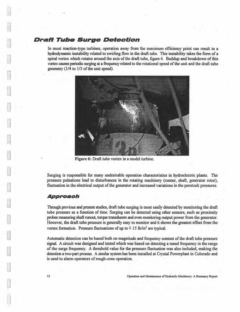
In most reaction-type turbines, operation away from the maximum efficiency point can result in a hydrodynamic instability related to swirling flow in the draft tube. This instability takes the form of a spiral vortex which rotates around the axis of the draft tube, figure 6. Buildup and breakdown of this vortex causes periodic surging at a frequency related to the rotational speed of the unit and the draft tube geometry (1/4 to 1/3 of the unit speed).
Figure 6: Draft tube vortex in a model turbine.
Surging is responsible for many undesirable operation characteristics in hydroelectric plants. The pressure pulsations lead to disturbances in the rotating machinecy (runner, shaft, generator rotor), fluctuation in the electrical output of the generator and increased variations in the penstock pressures.
Approaoh
Through previous and present studies, draft tube surging is most easily detected by monitoring the draft tube pressure as a function of time. Surging can be detected using other sensors, such as proximity probes measuring shaft nmout, torque transducers and even monitoring output power from the generator. However, the draft tube pressure is generally easy to monitor and it shows the greatest effect from the vortex formation. Pressure fluctuations ofup to+ 15 lb/in2 are typical.
Automatic detection can be based both on magnitude and frequency content of the draft tube pressure signal. A circuit was designed and tested which was based on detecting a tuned frequency in the range of the surge frequency. A threshold value for the pressure fluctuation was also included, making the detection a two-part process. A similar system has been installed at Crystal Powerplant in Colorado and is used to alarm operators of rough-wne operation.
12 Operation and Maintenance of Hydraulic Machinery: A Summary Report

Researchers have used various techniques to reduce the effects of draft tube surging. Perhaps the most effective method has been the injection of air into the draft tube, preferably directly beneath the runner. Various quantities of air are needed depending on the unit geometry and settings. Sometimes the quantity required is too large to be reasonable. The ability to interface the draft tube surge detector with some type of air injection system looks promising for automated operations.
Conolualon•
Draft tube surge detection is a straight-forward process and can easily be incorporated into a machine coodit:ioo mooitcxing system Operating alarms or even antoo1atic air injection are easily interfaced with the draft tube surge dctectoc developed by Reclamatioo. The major question remaining is how to use this information if operation flexibility is limited.
13 Operation and Maintenance of Hydraulic Machinery: A Summary Report
Turbine Aeration lo Enhanoe Downslrea,n Waler Quality A primary requirement for sustaining healthy fisheries and aquatic ecosystems is the presence of sufficient dissolved oxygen. In temperature-stratified reservoirs, DO is consumed deep in the reservoir by biological and chemical processes and is not replenished due to the lack of mixing inherent in stratification. The water quality problems created when this low-DO water is released through powerplants have become a special concern for many hydro operators. DO enhancement may be achieved by many methods, including reservoir mixing, reservoir aeration, and turbine aeration. In recent years, the Tennessee Valley Authority (TV A) has led efforts to improve turbine designs to incorporate turbine aeration. Projects administered by Reclamation have not had the same type of severe low-DO problems due mainly to reduced productivity of most western reservoirs and steep rivers with good natural reaeration properties. Reclamation has dealt with problems of nitrogen supersaturation downstream fran its dams foc many years and the resulting gas-bubble disease in local fish. Dissolved oxygen problems have been more limited, although there are some serious cases.
Baolcground
To date, Reclamation's major effort in DO enhancement by turbine aeration has occurred at Deer Creek Dam and Powerplant. Deer Creek Reservoir is located on the Provo River about 15 miles upstream of Provo, Utah. Owing late summer, releases from the reservoir are made entirely through the powerplant and often have DO concentrations ranging from O to 2 mg/I. The low-DO problem impacts about 2 to 3 miles of heavily used blue ribbon trout fishery on the Provo River below the dam.
During the winter of 1992-93, drought conditions caused Reclamation to restrict reservoir releases to about 85 percent of the required instream flow. To mitigate for this low-flow event, Reclamation proposed several alternatives for raising dissolved oxygen concentrations in the river downstream of the powerplant A project team with representatives from Recl~ation, the U.S. Fish and Wildlife Service, the Provo River Water Users Association, the Central Utah Water Conservancy District, the Utah Division of Wildlife Resources, and the National Biological Service was formed to address these alternatives.
Approaoh
During the SUDlQlef of 1993, Reclamation tested the feasibility of active turbine aeration during a 3-day test The literature which exists on turbine aeration to enhance DO levels has not previously dealt with a draft tube configuration like that at Deer Creek. With no formed elbow section, low flow velocities in the chamber leading to the tailrace exist, limiting the gas transfer.
Air was injected through the vacuum breaker systems and through the snorkel tube of each turbine unit. Pressmes within the turbines were well below atmospheric for all tested operating conditions, indicating that DO improvement was possible with passive aeration. Tests showed a IO-percent increase in
14 Operation and Maintenance of Hydraulic Machinery: A Sununary Report
aeraticn efficiency for each I-percent of air injected into the turbine up to a level of about 4-percent air (air discharge/turbine discharge).
Based on these results, turbine aeration was implemented during the summer of 1994. Low reservoir conditicns greatly aftected the amount of air which could be pulled into the unit passively. Air flow rates about 4 times less than in the 1993 tests were all that were possible. These low airflow rates led to disappointingly low increases in DO concentrations. Increases of 0.2 mg/I or less were predicted making detection of the rises unreliable.
Conoluslons
The Deer Creek results are similar to observations at the TV A's Cherokee Powerplant. The turbines at Cherokee are similar in size and head range to those at Deer Creek. TV A observed that the Cherokee units drew large quantities of air at maximum head conditions, but little or no air as the reservoir dropped toward its minimwn level. TV A has installed hub baffles on the runner and the resulting air flow rates are high for the entire range of operating heads. ·
The installation of hub baffles and/or blowers at Deer Creek would provide more consistent turbine aeration results at low heads. However, tests also revealed that weir aeration in the tailrace provides similar DO enhancement at similar operational costs without the initial capital outlay.
As a result of these studies, several other methods for aeration were reviewed. In general, the alternatives can be categorized as follows: forebay aeration or mixing; penstock aeration; turbine or draft tube aeration; and tailrace aeration using existing or specially designed weirs or aeration structures.
15 , Operation and Maintenance of Hydraulic Machinery: A Summary Report
Conclusions During the life of the project (PS006), many tasks were accomplished as indicated above. The majority of the recent effort has been in the area of cavitation detection in hydraulic turbines and evaluation of environmentally-safe greases for wicket gate applications. In addition, several other areas of interest have received complete <r partial :fimding frcm this research project. Furthe.r work is required in the area of cavitation detection to finalize the sensor development and integrate it into a machine condition monitoring system. Work has continued in this area with funding through Reclamation's Enterprise Funds. Application of our work on wicket gate greases and bushings along with the research of others can now allow recommendations to be given on replacement greases or bushings to Reclamation field offices.
Continued fimding through Reclamation's Research program in areas involved with new techniques and applications in operations and maintenance-related issues should be strongly considered. Many powerplant operators are in the position of needing proven technology for installation in their plants. However, technology development funds in this area have been lacking. This type of applied research is perhaps what our regional and area offices recognize most as a beneficial use of their contribution to Reclamation's overall research program.
16 Operation and Mainterwice of Hydraulic Machinery: A Sununary Report

Related Publications Frizell, K Warren, "Cavitation Detection in Hydraulic Turbines," Proceedings of Reclamation's Power
O&M Workshop, Laughlin, NV, May 1-3, 1995.
Fm.ell, K Warren, "Strain Measurements on the Runner of a Hydroelectric Turbine," Proceedings of the ASCE Symposium on Fundamentals and Advancements in Hydraulic Measurements and Experimentation, Buffalo, NY, August 1994.
Wahl, Tony L. and Morris M. Skinner, ''Evaluation of Techniques for Detection of Cavitation on the Runner of a Model Hydraulic Turbine," Report No. R-91-11, Bureau of Reclamation, December 1991.
Blum (Hanna), Leslie J. and Clifford A. Pugh, "Environmentally Safe "Green" Lubricants for Wicket Gates," Proceedings of Hydro Vision '94, Phoenix, AZ, August 1994.
Blum (Hanna), Leslie J., "Environmentally Safe Wicket Gate Lubrication," R&D News, HydroReview Magazine, August 1994.
Blum (Hanna), Leslie J., "Environmentally Safe Greases for Wicket Gate Bushing Applications," Presentation at the Northwest Powerpool Conference, March 1994.
Wahl, Tony L., ''Draft Tube Surging Times Two," HydroReview Magazine, February 1994.
Wahl, Tony L. and K. Warren Frizell, "Detecting the Twin Vortex Draft Tube Surge," Proceedings of the ASCE National Conference on Hydraulic Engineering, Nashville, TN, July 1991.
Frizell, K. Warren and J.C. Agee, "Varying Generator Excitation to Control Draft Tube Surge," Proceedings ofWaterPower '91, Denver, CO, July 1991.
Wahl, Tony L. and Doug Young, ''Dissolved Oxygen Enhancement on the Provo River," Proceedings ofWaterPower 95, San Francisco, CA, July 25-28, 1995.
Wahl, Tony L. "Venting Hydroturbines for Dissolved Oxygen Enhancement," Proceedings of Reclamation's Power O&M Workshop, Laughlin, NV, May 1-3, 1995.
Fm.ell, K. Warren, Brent W. Mefford and Morris M. Skinner, "Data Acquisition Techniques for Rotating Machinery," Proceedings of the ASCE National Conference on Hydraulic Engineering, Nashville, TN, July 1991.
17 Operation and Maintenance of Hydraulic Machinery: A Summary Report