operation and safety manual - master hire · operation and safety manual ... jlg representative for...
TRANSCRIPT
Operation and Safety Manual
ANSI ®
Original Instructions - Keep this manual with the machine at all times.
Boom Lift Models340AJ
3121258May 16, 2012


FOREWORD
a
l times.
lessors, and lessees with the precautions anderation for its intended purpose.
erves the right to make specification changesformation.
3121258 – JLG Lift –
FOREWORD
This manual is a very important tool! Keep it with the machine at al
The purpose of this manual is to provide owners, users, operators,operating procedures essential for the safe and proper machine op
Due to continuous product improvements, JLG Industries, Inc. reswithout prior notification. Contact JLG Industries, Inc. for updated in

FOREWORD
b 3121258
SIGNAL WORDS
INDIAVOWIL
INDAVODEC
OTENTIALLY HAZARDOUS SITUATION. IF NOTRESULT IN MINOR OR MODERATE INJURY. IT MAYINST UNSAFE PRACTICES. THIS DECAL WILL HAVE AOUND.
IMPORTANTRMATION OR A COMPANY POLICY THAT RELATESDIRECTLY TO THE SAFETY OF PERSONNEL OR PRO-PERTY.
the potential personalymbol to avoid possible
– JLG Lift –
SAFETY ALERT SYMBOLS AND SAFETY
CATES AN IMMINENTLY HAZARDOUS SITUATION. IF NOTIDED, WILL RESULT IN SERIOUS INJURY OR DEATH. THIS DECALL HAVE A RED BACKGROUND.
ICATES A POTENTIALLY HAZARDOUS SITUATION. IF NOTIDED, COULD RESULT IN SERIOUS INJURY OR DEATH. THISAL WILL HAVE AN ORANGE BACKGROUND.
INDICATES A PAVOIDED, MAY ALSO ALERT AGAYELLOW BACKGR
INDICATES INFODIRECTLY OR INTECTION OF PRO
This is the Safety Alert Symbol. It is used to alert you toinjury hazards. Obey all safety messages that follow this sinjury or death
FOREWORD
c
act:
uct Safety and Reliability Department Industries, Inc.4 Fountainhead Plaza
erstown, MD 21742
our Local JLG Office addresses on inside of manual cover)
A:
Free: 877-JLG-SAFE (877-554-7233)
ide USA:
ne: 240-420-2661 301-745-3713ail: [email protected]
ent Reporting
ct Safety Publica-
nt Owner Updates
tions Regarding ct Safety
• Standards and Regulations Compliance Information
• Questions Regarding Spe-cial Product Applications
• Questions Regarding Prod-uct Modifications
3121258 – JLG Lift –
THIS PRODUCT MUST COMPLY WITH ALL SAFETY RELATED BULLE-TINS. CONTACT JLG INDUSTRIES, INC. OR THE LOCAL AUTHORIZEDJLG REPRESENTATIVE FOR INFORMATION REGARDING SAFETY-RELATED BULLETINS WHICH MAY HAVE BEEN ISSUED FOR THISPRODUCT.
IMPORTANTJLG INDUSTRIES, INC. SENDS SAFETY RELATED BULLETINS TO THEOWNER OF RECORD OF THIS MACHINE. CONTACT JLG INDUSTRIES,INC. TO ENSURE THAT THE CURRENT OWNER RECORDS AREUPDATED AND ACCURATE.
IMPORTANTJLG INDUSTRIES, INC. MUST BE NOTIFIED IMMEDIATELY IN ALLINSTANCES WHERE JLG PRODUCTS HAVE BEEN INVOLVED IN ANACCIDENT INVOLVING BODILY INJURY OR DEATH OF PERSONNEL ORWHEN SUBSTANTIAL DAMAGE HAS OCCURRED TO PERSONAL PROP-ERTY OR THE JLG PRODUCT.
Cont
ProdJLG1322HagUSA
or Y(See
In US
Toll
Outs
PhoFax:E-m
For:• Accid
• Produtions
• Curre
• QuesProdu

FOREWORD
d 3121258
O
R
R
R
– JLG Lift –
REVISION LOG
riginal Issue - June 17, 2010
evised - December 20, 2010
evised - March 17, 2011
evised - May 16, 2012

TABLE OF CONTENTS
3121 i
SEC - PARAGRAPH, SUBJECT PAGE
SEC
SECRA
General . . . . . . . . . . . . . . . . . . . . . . . . . . . . . . . . 2-9OSCILLATING AXLE LOCKOUT TEST (IF EQUIPPED) . . . . . . . . . . . . . . . . . . . . . . . . . . . 2-11
- 3 - MACHINE CONTROLS AND INDICATORS
GENERAL . . . . . . . . . . . . . . . . . . . . . . . . . . . . . . . . 3-1CONTROLS AND INDICATORS . . . . . . . . . . . . . . . 3-1
Ground Control Station . . . . . . . . . . . . . . . . . . . . 3-2Ground Control Indicator Panel . . . . . . . . . . . . . 3-6Platform Station . . . . . . . . . . . . . . . . . . . . . . . . . . 3-8Platform Control Indicator Panel . . . . . . . . . . . . 3-12
- 4 - MACHINE OPERATION
DESCRIPTION. . . . . . . . . . . . . . . . . . . . . . . . . . . . . 4-1BOOM OPERATING CHARACTERISTICS AND LIMITATIONS . . . . . . . . . . . . . . . . . . . . . . . . . . . . . 4-2
Capacities . . . . . . . . . . . . . . . . . . . . . . . . . . . . . . 4-2Stability . . . . . . . . . . . . . . . . . . . . . . . . . . . . . . . . 4-2
ENGINE OPERATION . . . . . . . . . . . . . . . . . . . . . . . 4-2Starting Procedure . . . . . . . . . . . . . . . . . . . . . . . 4-2Shutdown Procedure . . . . . . . . . . . . . . . . . . . . . 4-3Fuel Reserve / Shut-Off System (Gas or Diesel En-gines Only) . . . . . . . . . . . . . . . . . . . . . . . . . . . . . 4-3
TRAVELING (DRIVING) . . . . . . . . . . . . . . . . . . . . . . 4-6Traveling Forward and Reverse . . . . . . . . . . . . . 4-8
258 – JLG Lift –
TION - PARAGRAPH, SUBJECT PAGE SECTION
TION - 1 - SAFETY PRECAUTIONS
1.1 GENERAL . . . . . . . . . . . . . . . . . . . . . . . . . . . . . . . . .1-11.2 PRE-OPERATION . . . . . . . . . . . . . . . . . . . . . . . . . . .1-1
Operator Training and Knowledge. . . . . . . . . . . 1-1Workplace Inspection. . . . . . . . . . . . . . . . . . . . . 1-2Machine Inspection . . . . . . . . . . . . . . . . . . . . . . 1-2
1.3 OPERATION . . . . . . . . . . . . . . . . . . . . . . . . . . . . . . .1-3General . . . . . . . . . . . . . . . . . . . . . . . . . . . . . . . . 1-3Trip and Fall Hazards . . . . . . . . . . . . . . . . . . . . . 1-3Electrocution Hazards . . . . . . . . . . . . . . . . . . . . 1-4Tipping Hazards . . . . . . . . . . . . . . . . . . . . . . . . . 1-6Crushing and Collision Hazards. . . . . . . . . . . . . 1-7
1.4 TOWING, LIFTING, AND HAULING . . . . . . . . . . . . .1-81.5 ADDITIONAL HAZARDS / SAFETY . . . . . . . . . . . . .1-9
TION - 2 - USER RESPONSIBILITIES, MACHINE PREPA-TION, AND INSPECTION
2.1 PERSONNEL TRAINING . . . . . . . . . . . . . . . . . . . . .2-1Operator Training . . . . . . . . . . . . . . . . . . . . . . . . 2-1Training Supervision. . . . . . . . . . . . . . . . . . . . . . 2-1Operator Responsibility . . . . . . . . . . . . . . . . . . . 2-1
2.2 PREPARATION, INSPECTION, AND MAINTENANCE . . . . . . . . . . . . . . . . . . . . . . . . . . . .2-2
Pre-Start Inspection . . . . . . . . . . . . . . . . . . . . . . 2-4Function Check. . . . . . . . . . . . . . . . . . . . . . . . . . 2-5
2.3
SECTION
3.13.2
SECTION
4.14.2
4.3
4.3

TABLE OF CONTENTS
ii 3121258
SECTIO RAGRAPH, SUBJECT PAGE
4.44.5
4.6
4.74.8
4.9
4.10
SECTION
5.15.25.3
ILIARY DESCENT SYSTEM. . . . . . . . . . . . . . . .5-2UAL SWING OVERRIDE . . . . . . . . . . . . . . . . . .5-2RGENCY TOWING PROCEDURES . . . . . . . . .5-4
GENERAL SPECIFICATIONS & OPERATOR CE
ODUCTION. . . . . . . . . . . . . . . . . . . . . . . . . . . .6-1RATING SPECIFICATIONS AND PERFORMANCE A . . . . . . . . . . . . . . . . . . . . . . . . . . . . . . . . . . . .6-1
perating Specifications . . . . . . . . . . . . . . . . . . 6-1imensional Data . . . . . . . . . . . . . . . . . . . . . . . . 6-2apacities . . . . . . . . . . . . . . . . . . . . . . . . . . . . . . 6-2res . . . . . . . . . . . . . . . . . . . . . . . . . . . . . . . . . . 6-3gine Data . . . . . . . . . . . . . . . . . . . . . . . . . . . . 6-3
ydraulic Oil . . . . . . . . . . . . . . . . . . . . . . . . . . . . 6-4ajor Component Weights. . . . . . . . . . . . . . . . . 6-9RATOR MAINTENANCE . . . . . . . . . . . . . . . . .6-13S & WHEELS . . . . . . . . . . . . . . . . . . . . . . . . .6-18
re Replacement . . . . . . . . . . . . . . . . . . . . . . . 6-18heel and Tire Replacement . . . . . . . . . . . . . . 6-19heel Installation . . . . . . . . . . . . . . . . . . . . . . . 6-19
– JLG Lift –
N - PARAGRAPH, SUBJECT PAGE SECTION - PA
STEERING . . . . . . . . . . . . . . . . . . . . . . . . . . . . . . . . 4-8PLATFORM . . . . . . . . . . . . . . . . . . . . . . . . . . . . . . . 4-8
Platform Level Adjustment . . . . . . . . . . . . . . . . . 4-8Platform Rotation . . . . . . . . . . . . . . . . . . . . . . . . 4-8
BOOM . . . . . . . . . . . . . . . . . . . . . . . . . . . . . . . . . . . 4-9Swinging the Boom . . . . . . . . . . . . . . . . . . . . . . 4-9Raising and Lowering the Tower Boom . . . . . . 4-9
FUNCTION SPEED CONTROL . . . . . . . . . . . . . . . 4-10DUAL FUEL SYSTEM (GAS ENGINE ONLY) . . . . 4-10
Changing From Gasoline to LP Gas . . . . . . . . 4-10Changing From LP Gas to Gasoline . . . . . . . . 4-10
SHUT DOWN AND PARK . . . . . . . . . . . . . . . . . . . 4-10Shut Down and Park . . . . . . . . . . . . . . . . . . . . 4-10Storage Position. . . . . . . . . . . . . . . . . . . . . . . . 4-13
LIFTING AND TIE DOWN. . . . . . . . . . . . . . . . . . . . 4-13Lifting . . . . . . . . . . . . . . . . . . . . . . . . . . . . . . . . 4-13Tie Down . . . . . . . . . . . . . . . . . . . . . . . . . . . . . 4-13
- 5 - EMERGENCY PROCEDURES
GENERAL . . . . . . . . . . . . . . . . . . . . . . . . . . . . . . . . 5-1INCIDENT NOTIFICATION. . . . . . . . . . . . . . . . . . . . 5-1EMERGENCY OPERATION. . . . . . . . . . . . . . . . . . . 5-1
Operator Unable to Control Machine . . . . . . . . 5-1Platform or Boom Caught Overhead. . . . . . . . . 5-2
5.4 AUX5.5 MAN5.6 EME
SECTION - 6 - MAINTENAN
6.1 INTR6.2 OPE
DATODCTiEnHM
6.3 OPE6.4 TIRE
TiWW

TABLE OF CONTENTS
3121 iii
SEC - PARAGRAPH, SUBJECT PAGE
SEC
Decal Location Sheet 6 of 10 . . . . . . . . . . . . . . . . 4-20Decal Location Sheet 7 of 10 . . . . . . . . . . . . . . . . 4-21Decal Location Sheet 8 of 10 . . . . . . . . . . . . . . . . 4-22Decal Location Sheet 9 of 10 . . . . . . . . . . . . . . . . 4-23Decal Location Sheet 10 of 10 . . . . . . . . . . . . . . . 4-24Auxiliary Descent Decal and Hand Pump . . . . . . . 5-3Oil Sampling Port . . . . . . . . . . . . . . . . . . . . . . . . . . 6-6Hydraulic Oil Operation Chart - Sheet 1 of 2 . . . . . 6-7Hydraulic Oil Operation Chart - Sheet 2 of 2 . . . . . 6-8Engine Oil Operation Chart - GM . . . . . . . . . . . . . 6-10Engine Oil Operation Chart - Kubota . . . . . . . . . . 6-11Operator Maintenance and Lubrication Diagram. 6-12
258 – JLG Lift –
TION - PARAGRAPH, SUBJECT PAGE SECTION
6.5 SUPPLEMENTAL INFORMATION . . . . . . . . . . . . .6-20
TION - 7 - INSPECTION AND REPAIR LOG
LIST OF FIGURES
2-1. Basic Nomenclature. . . . . . . . . . . . . . . . . . . . . . . . .2-72-2. Daily Walk-Around Inspection - Sheet 1 of 3 . . . . . .2-82-3. Daily Walk-Around Inspection - Sheet 2 of 3 . . . . . .2-92-4. Daily Walk-Around Inspection - Sheet 3 of 3 . . . . .2-103-1. Ground Control Station . . . . . . . . . . . . . . . . . . . . . .3-33-2. Ground Control Indicator Panel . . . . . . . . . . . . . . . .3-73-3. Platform Control Console. . . . . . . . . . . . . . . . . . . . .3-93-4. Platform Control Indicator Panel . . . . . . . . . . . . . .3-134-1. Position of Least Forward Stability . . . . . . . . . . . . .4-44-2. Position of Least Backward Stability . . . . . . . . . . . .4-54-3. Grade and Side Slopes . . . . . . . . . . . . . . . . . . . . . .4-74-4. Stowed Position . . . . . . . . . . . . . . . . . . . . . . . . . . .4-114-5. Storage Position. . . . . . . . . . . . . . . . . . . . . . . . . . .4-124-6. Lifting and Tie Down Chart . . . . . . . . . . . . . . . . . .4-144-7. Decal Location Sheet 1 of 10. . . . . . . . . . . . . . . . .4-154-8. Decal Location Sheet 2 of 10. . . . . . . . . . . . . . . . .4-164-9. Decal Location Sheet 3 of 10. . . . . . . . . . . . . . . . .4-174-10. Decal Location Sheet 4 of 10. . . . . . . . . . . . . . . . .4-184-11. Decal Location Sheet 5 of 10. . . . . . . . . . . . . . . . .4-19
4-12.4-13.4-14.4-15.4-16.5-1.6-1.6-2.6-3.6-4.6-5.6-6.
TABLE OF CONTENTS
iv 3121258
SECTIO RAGRAPH, SUBJECT PAGE
1-11-22-16-16-26-36-46-56-66-76-86-96-107-1
– JLG Lift –
N - PARAGRAPH, SUBJECT PAGE SECTION - PA
LIST OF TABLES
Minimum Approach Distances (M.A.D.) . . . . . . . . . 1-5Beaufort Scale (For Reference Only) . . . . . . . . . . 1-10Inspection and Maintenance Table . . . . . . . . . . . . . 2-3Operating Specifications . . . . . . . . . . . . . . . . . . . . . 6-1Dimensional Data. . . . . . . . . . . . . . . . . . . . . . . . . . . 6-2Capacities . . . . . . . . . . . . . . . . . . . . . . . . . . . . . . . . 6-2Tires . . . . . . . . . . . . . . . . . . . . . . . . . . . . . . . . . . . . . 6-3Kubota D1105-E3. . . . . . . . . . . . . . . . . . . . . . . . . . . 6-3GM 0.97L . . . . . . . . . . . . . . . . . . . . . . . . . . . . . . . . . 6-4Hydraulic Oil . . . . . . . . . . . . . . . . . . . . . . . . . . . . . . 6-4Critical Stability Weights . . . . . . . . . . . . . . . . . . . . . 6-9Lubrication Specifications. . . . . . . . . . . . . . . . . . . 6-13Wheel Torque Chart. . . . . . . . . . . . . . . . . . . . . . . . 6-20Inspection and Repair Log . . . . . . . . . . . . . . . . . . . 7-1

SECTION 1 - SAFETY PRECAUTIONS
1-1
CAUTIONS
E-OPERATION
Training and Knowledged and understand this manual before operating thehine.
not operate this machine until complete training is per-ed by authorized persons.
y authorized and qualified personnel can operate thehine.
3121258 – JLG Lift –
SECTION 1. SAFETY PRE
1.1 GENERALThis section outlines the necessary precautions for properand safe machine operation and maintenance. For propermachine use, it is mandatory that a daily routine is estab-lished based on the content of this manual. A maintenanceprogram, using the information provided in this manual andthe Service and Maintenance Manual, must also be estab-lished by a qualified person and followed to ensure themachine is safe to operate.
The owner/user/operator/lessor/lessee of the machineshould not operate the machine until this manual has beenread, training is accomplished, and operation of the machinehas been completed under the supervision of an experi-enced and qualified operator.
If there are any questions with regard to safety, training,inspection, maintenance, application, and operation, pleasecontact JLG Industries, Inc. (“JLG”).
FAILURE TO COMPLY WITH THE SAFETY PRECAUTIONS LISTED INTHIS MANUAL COULD RESULT IN MACHINE DAMAGE, PROPERTY DAM-AGE, PERSONAL INJURY OR DEATH.
1.2 PR
Operator• Rea
mac
• Do form
• Onlmac

SECTION 1 - SAFETY PRECAUTIONS
1-2 3121258
Wo
pection achine operation, perform inspections and func-
hecks. Refer to Section 2 of this manual for instructions.
perate this machine until it has been serviced anded according to requirements specified in theand Maintenance Manual.
the footswitch and all other safety devices areg properly. Modification of these devices is aolation.
R ALTERATION OF AN AERIAL WORK PLATFORMONLY WITH WRITTEN PERMISSION FROM THE MANU-
perate any machine on which safety or instruction or decals are missing or illegible.
ny buildup of debris on the platform floor. Keep, grease, and other slippery substances from foot-d platform floor.
– JLG Lift –
• Read, understand, and obey all DANGERS, WARNINGS,CAUTIONS, and operating instructions on the machineand in this manual.
• Use the machine in a manner which is within the scope ofits intended application set by JLG.
• All operating personnel must be familiar with the emer-gency controls and emergency operation of the machineas specified in this manual.
• Read, understand, and obey all applicable employer,local, and governmental regulations as they pertain tooperation of the machine.
rkplace Inspection• The operator is to take safety measures to avoid all haz-
ards in the work area prior to machine operation.
• Do not operate or raise the platform while on trucks, trail-ers, railway cars, floating vessels, scaffolds or other equip-ment unless approved in writing by JLG.
• Do not operate the machine in hazardous environmentsunless approved for that purpose by JLG.
• Be sure that the ground conditions are able to support themaximum load shown on the decals located on themachine.
Machine Ins• Before m
tional cdetailed
• Do not omaintainService
• Be sureoperatinsafety vi
MODIFICATION OSHALL BE MADE FACTURER
• Do not oplacards
• Avoid amud, oilwear an
SECTION 1 - SAFETY PRECAUTIONS
1-3
plies or tools which extend outside the platform arehibited unless approved by JLG.
en driving, always position boom over rear axle in line the direction of travel. Remember, if boom is over thet axle, steer and drive functions will be reversed.
not assist a stuck or disabled machine by pushing,ing, or by using boom functions. Only pull the unit the tie-down lugs on the chassis.
not place boom or platform against any structure tody the platform or to support the structure.
w boom and shut off all power before leaving machine.
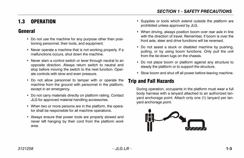
Fall Hazards operation, occupants in the platform must wear a fullarness with a lanyard attached to an authorized lan-
nchorage point. Attach only one (1) lanyard per lan-nchorage point.
3121258 – JLG Lift –
1.3 OPERATION
General • Do not use the machine for any purpose other than posi-
tioning personnel, their tools, and equipment.
• Never operate a machine that is not working properly. If amalfunctions occurs, shut down the machine.
• Never slam a control switch or lever through neutral to anopposite direction. Always return switch to neutral andstop before moving the switch to the next function. Oper-ate controls with slow and even pressure.
• Do not allow personnel to tamper with or operate themachine from the ground with personnel in the platform,except in an emergency.
• Do not carry materials directly on platform railing. ContactJLG for approved material handling accessories.
• When two or more persons are in the platform, the opera-tor shall be responsible for all machine operations.
• Always ensure that power tools are properly stowed andnever left hanging by their cord from the platform workarea.
• Suppro
• Whwithfron
• Do pullfrom
• Do stea
• Sto
Trip and Duringbody hyard ayard a

SECTION 1 - SAFETY PRECAUTIONS
1-4 3121258
reme caution when entering or leaving platform. that the boom is fully lowered. It may be neces-elescope out to position the platform closer to thefor entry/exit. Face the machine, maintain “threentact” with the machine, using two hands and one
o feet and one hand during entry and exit.
n Hazardschine is not insulated and does not provide pro-rom contact or proximity to electrical current.
– JLG Lift –
• Before operating the machine, make sure all gates areclosed and fastened in their proper position.
• Keep both feet firmly positioned on the platform floor at alltimes. Never use ladders, boxes, steps, planks, or similaritems on platform to provide additional reach.
• Never use the boom assembly to enter or leave the plat-form.
• Use extBe suresary to tground point cofoot or tw
Electrocutio• This ma
tection f

SECTION 1 - SAFETY PRECAUTIONS
1-5
in a clearance of at least 10 ft. (3m) between any part machine and its occupants, their tools, and their
ent from any electrical line or apparatus carrying up00 volts. One foot additional clearance is required for
additional 30,000 volts or less.
1-1. Minimum Approach Distances (M.A.D.)
oltage Rangease to Phase)
MINIMUM APPROACH DISTANCEin Feet (Meters)
0 to 50 KV 10 (3)
r 50KV to 200 KV 15 (5)
200 KV to 350 KV 20 (6)
350 KV to 500 KV 25 (8)
500 KV to 750 KV 35 (11)
50 KV to 1000 KV 45 (14)
This requirement shall apply except whereemployer, local or governmental regulationsare more stringent.
3121258 – JLG Lift –
• Maintain distance from electrical lines, apparatus, or anyenergized (exposed or insulated) parts according to theMinimum Approach Distance (MAD) as shown in Table 1-1.
• Allow for machine movement and electrical line swaying.
• Maintaof theequipmto 50,0every
Table
V(Ph
Ove
Over
Over
Over
Over 7
NOTE:

SECTION 1 - SAFETY PRECAUTIONS
1-6 3121258
•
DO ZONENE
ardsr must be familiar with the surface before driving.exceed the allowable sideslope and grade while
– JLG Lift –
The minimum approach distance may be reduced if insulat-ing barriers are installed to prevent contact, and the barriersare rated for the voltage of the line being guarded. Thesebarriers shall not be part of (or attached to) the machine. Theminimum approach distance shall be reduced to a distancewithin the designed working dimensions of the insulatingbarrier. This determination shall be made by a qualified per-son in accordance with the employer, local, or governmentalrequirements for work practices near energized equipment.
NOT MANEUVER MACHINE OR PERSONNEL INSIDE PROHIBITEDE (MAD). ASSUME ALL ELECTRICAL PARTS AND WIRING ARERGIZED UNLESS KNOWN OTHERWISE.
Tipping Haz• The use
Do not driving.

SECTION 1 - SAFETY PRECAUTIONS
1-7
oom assembly or platform is in a position that one ore wheels are off the ground, all persons must beoved before attempting to stabilize the machine. Usees, forklift trucks, or other appropriate equipment toilize machine.
and Collision Hazardsroved head gear must be worn by all operating and
und personnel.
ck work area for clearances overhead, on sides, andom of platform when lifting or lowering platform, anding.
ing operation, keep all body parts inside platform rail-
3121258 – JLG Lift –
• Do not elevate platform or drive with platform elevatedwhile on a sloping, uneven, or soft surface.
• Before driving on floors, bridges, trucks, and other sur-faces, check allowable capacity of the surfaces.
• Never exceed the maximum platform capacity. Distributeloads evenly on platform floor.
• Do not raise the platform or drive from an elevated posi-tion unless the machine is on firm, level and smooth sur-faces.
• Keep the chassis of the machine at least 2 ft. (0.6m) fromholes, bumps, drop-offs, obstructions, debris, concealedholes, and other potential hazards on the floor/surface.
• Do not push or pull any object with the boom.
• Never attempt to use the machine as a crane. Do not tie-off machine to any adjacent structure.
• Do not operate the machine when wind conditions exceed28 mph (12.5 m/s). Refer to Table 1-2, Beaufort Scale (ForReference Only).
• Do not increase the surface area of the platform or theload. Increase of the area exposed to the wind willdecrease stability.
• Do not increase the platform size with unauthorized deckextensions or attachments.
• If bmorremcranstab
Crushing• App
gro
• Chebottdriv
• During.
SECTION 1 - SAFETY PRECAUTIONS
1-8 3121258
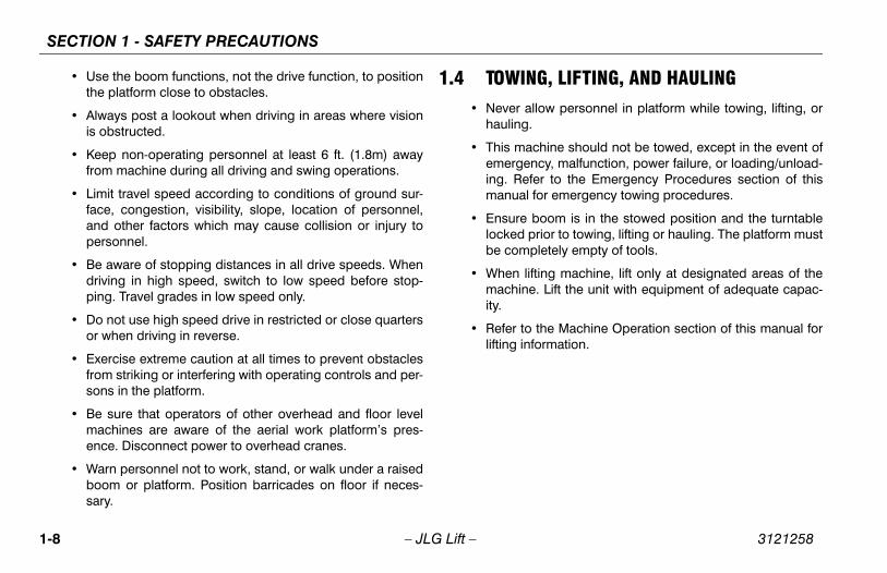
G, LIFTING, AND HAULINGllow personnel in platform while towing, lifting, or
chine should not be towed, except in the event ofcy, malfunction, power failure, or loading/unload-
er to the Emergency Procedures section of thisfor emergency towing procedures.
boom is in the stowed position and the turntablerior to towing, lifting or hauling. The platform mustletely empty of tools.
ting machine, lift only at designated areas of the. Lift the unit with equipment of adequate capac-
the Machine Operation section of this manual forormation.
– JLG Lift –
• Use the boom functions, not the drive function, to positionthe platform close to obstacles.
• Always post a lookout when driving in areas where visionis obstructed.
• Keep non-operating personnel at least 6 ft. (1.8m) awayfrom machine during all driving and swing operations.
• Limit travel speed according to conditions of ground sur-face, congestion, visibility, slope, location of personnel,and other factors which may cause collision or injury topersonnel.
• Be aware of stopping distances in all drive speeds. Whendriving in high speed, switch to low speed before stop-ping. Travel grades in low speed only.
• Do not use high speed drive in restricted or close quartersor when driving in reverse.
• Exercise extreme caution at all times to prevent obstaclesfrom striking or interfering with operating controls and per-sons in the platform.
• Be sure that operators of other overhead and floor levelmachines are aware of the aerial work platform’s pres-ence. Disconnect power to overhead cranes.
• Warn personnel not to work, stand, or walk under a raisedboom or platform. Position barricades on floor if neces-sary.
1.4 TOWIN• Never a
hauling.
• This maemergening. Refmanual
• Ensure locked pbe comp
• When lifmachineity.
• Refer tolifting inf

SECTION 1 - SAFETY PRECAUTIONS
1-9
not refuel the machine with the engine running.
tery fluid is highly corrosive. Avoid contact with skin clothing at all times.
rge batteries only in a well ventilated area.
3121258 – JLG Lift –
1.5 ADDITIONAL HAZARDS / SAFETY• Do not use machine as a ground for welding.
• When performing welding or metal cutting operations,precautions must be taken to protect the chassis fromdirect exposure to weld and metal cutting spatter.
• Do
• Batand
• Cha

SECTION 1 - SAFETY PRECAUTIONS
1-1 3121258
DO NMPH
Only)
Land Conditions
ertically
n smoke
skin. Leaves rustle
wigs in constant motion
r raised. Small branches begin to move.
tion. Whistling heard in overhead wires. es difficult.
n. Effort needed to walk against the wind.
ees. Cars veer on road.
ge.
0 – JLG Lift –
OT OPERATE THE MACHINE WHEN WIND CONDITIONS EXCEED 28 (12.5 M/S).
Table 1-2. Beaufort Scale (For Reference
Beaufort Number
Wind SpeedDescription
mph m/s
0 0 0-0.2 Calm Calm. Smoke rises v
1 1-3 0.3-1.5 Light air Wind motion visible i
2 4-7 1.6-3.3 Light breeze Wind felt on exposed
3 8-12 3.4-5.4 Gentle breeze Leaves and smaller t
4 13-18 5.5-7.9 Moderate breeze Dust and loose pape
5 19-24 8.0-10.7 Fresh breeze Smaller trees sway.
6 25-31 10.8-13.8 Strong breeze Large branches in moUmbrella use becom
7 32-38 13.9-17.1 Near Gale/Moderate Gale Whole trees in motio
8 39-46 17.2-20.7 Fresh Gale Twigs broken from tr
9 47-54 20.8-24.4 Strong Gale Light structure dama

CHINE PREPARATION, AND INSPECTION
2-1
PREPARATION, AND INSPECTION
e safest means to operate the machine where over-ad obstructions, other moving equipment, and obsta-
es, depressions, holes, or drop-offs exist.
eans to avoid the hazards of unprotected electricalnductors.
ecific job requirements or machine application.
Supervisiong must be done under the supervision of a qualified in an open area free of obstructions until the traineeveloped the ability to safely control and operate the
ne.
Responsibilityerator must be instructed that he/she has the respon-
and authority to shut down the machine in case of action or other unsafe condition of either the machinejob site.
SECTION 2 - USER RESPONSIBILITIES, MA
3121258 – JLG Lift –
SECTION 2. USER RESPONSIBILITIES, MACHINE
2.1 PERSONNEL TRAININGThe aerial platform is a personnel handling device; so it isnecessary that it be operated and maintained only by trainedpersonnel.
Persons under the influence of drugs or alcohol or who aresubject to seizures, dizziness or loss of physical control mustnot operate this machine.
Operator TrainingOperator training must cover:
1. Use and limitations of the controls in the platform and atthe ground, emergency controls and safety systems.
2. Control labels, instructions, and warnings on themachine.
3. Rules of the employer and government regulations.
4. Use of approved fall protection device.
5. Enough knowledge of the mechanical operation of themachine to recognize a malfunction or potential mal-function.
6. Thhecl
7. Mco
8. Sp
Training Traininpersonhas demachi
OperatorThe opsibilitymalfunor the

SECTION 2 - USER RESPONSIBILITIES, MACHINE PREPARATION, AND INSPECTION
2-2 3121258
2.2, INC. RECOGNIZES A FACTORY-TRAINED SERVICEA PERSON WHO HAS SUCCESSFULLY COMPLETED TRAINING SCHOOL FOR THE SPECIFIC JLG PRODUCT
– JLG Lift –
PREPARATION, INSPECTION, AND MAINTENANCE
The following table covers the periodic machine inspectionsand maintenance required by JLG Industries, Inc. Consultlocal regulations for further requirements for aerial work plat-forms. The frequency of inspections and maintenance mustbe increased as necessary when the machine is used in aharsh or hostile environment, if the machine is used withincreased frequency, or if the machine is used in a severemanner.
JLG INDUSTRIESTECHNICIAN AS THE JLG SERVICEMODEL.

CHINE PREPARATION, AND INSPECTION
2-3
ance Table
ryibility
Service Qualification
Reference
or User or Operator Operator and Safety Manual
or User Qualified JLG Mechanic
Service and Maintenance Manual and applicable JLG inspection form
or User Qualified JLG Mechanic
Service and Maintenance Manual and applicable JLG inspection form
or User Factory-TrainedService Technician(Recommended)
Service and Maintenance Manual and applicable JLG inspection form
or User Qualified JLG Mechanic
Service and Maintenance Manual
nce Manual to perform inspections.
SECTION 2 - USER RESPONSIBILITIES, MA
3121258 – JLG Lift –
Table 2-1. Inspection and Mainten
Type Frequency PrimaRespons
Pre-Start Inspection Before using each day; or whenever there’s an Operator change.
User or Operat
Pre-Delivery Inspection (See Note)
Before each sale, lease, or rental delivery. Owner, Dealer,
Frequent Inspection(See Note)
In service for 3 months or 150 hours, whichever comes first; orOut of service for a period of more than 3 months; orPurchased used.
Owner, Dealer,
Annual Machine Inspec-tion(See Note)
Annually, no later than 13 months from the date of prior inspection.
Owner, Dealer,
Preventative Maintenance At intervals as specified in the Service and Main-tenance Manual.
Owner, Dealer,
NOTE: Inspection forms are available from JLG. Use the Service and Maintena

SECTION 2 - USER RESPONSIBILITIES, MACHINE PREPARATION, AND INSPECTION
2-4 3121258
Pre tion and Safety Manuals – Make sure a copy oferator and Safety Manual, AEM Safety Manual
markets only), and ANSI Manual of Responsibili-NSI markets only) is enclosed in the weathernt storage container.
-Around” Inspection – Refer to Figure 2-2.
y – Charge as required.
ombustion Engine Powered Machines) – Add the fuel as necessary.
e Oil Supply - Ensure the engine oil level is at the ark on the dipstick and the filler cap is secure.
ulic Oil – Check the hydraulic oil level. Ensurelic oil is added as required.
sories/Attachments - Reference the Operatorafety Manual of each attachment or accessoryd upon the machine for specific inspection, oper-
and maintenance instructions.
– JLG Lift –
-Start InspectionThe Pre-Start Inspection should include each of the follow-ing:
1. Cleanliness – Check all surfaces for leakage (oil, fuel,or battery fluid) or foreign objects. Report any leakage tothe proper maintenance personnel.
2. Structure - Inspect the machine structure for dents,damage, weld or parent metal cracks or other discrep-ancies.
3. Decals and Placards – Check all for cleanliness andlegibility. Make sure none of the decals and placards aremissing. Make sure all illegible decals and placards arecleaned or replaced.
4. Operathe Op(ANSI ties (Aresista
5. “Walk
6. Batter
7. Fuel (Cproper
8. EnginFull m
9. Hydrahydrau
10. Accesand Sinstalleation,
Parent Metal Crack Weld Crack
CHINE PREPARATION, AND INSPECTION
2-5
Check the Function Check as follows:
om the ground control console with no load in theatform:
. Check that all guards protecting the switches orlocks are in place;
. Operate all functions and ensure proper operation;
. Check auxiliary descent and ensure proper opera-tion;
. Ensure that all machine functions are disabledwhen the Emergency Stop Button is pushed in.
. Ensure all boom functions stop when the functionenable switch is released.
SECTION 2 - USER RESPONSIBILITIES, MA
3121258 – JLG Lift –
11. Function Check – Once the “Walk-Around” Inspectionis complete, perform a functional check of all systems inan area free of overhead and ground level obstructions.Refer to Section 4 for more specific operating instruc-tions.
IF THE MACHINE DOES NOT OPERATE PROPERLY, TURN OFF THEMACHINE IMMEDIATELY! REPORT THE PROBLEM TO THE PROPERMAINTENANCE PERSONNEL. DO NOT OPERATE THE MACHINE UNTIL ITIS DECLARED SAFE FOR OPERATION.
FunctionPerform
1. Frpl
a
b
c
d
e

SECTION 2 - USER RESPONSIBILITIES, MACHINE PREPARATION, AND INSPECTION
2-6 3121258
the boom over either of the rear tires and ensuree Drive Orientation indicator illuminates and thative Orientation Override switch must be used forve function to operate.
– JLG Lift –
2. From the platform control console:
a. Ensure that the control console is firmly secured inthe proper location;
b. Check that all guards protecting the switches orlocks are in place;
c. Operate all functions and ensure proper operation;
d. Ensure that all machine functions are disabledwhen the Emergency Stop Button is pushed in.
e. Ensure that all machine functions stop when thefootswitch is released.
3. With the platform in the stowed position:
a. Drive the machine on a grade, not to exceed therated gradeability, and stop to ensure the brakeshold;
b. Check that the tilt indicator is illuminated to ensureproper operation.
4. Swingthat ththe Drthe dri

CHINE PREPARATION, AND INSPECTION
2-7
1
2
ure
1. Platform2. Platform Console3. Jib4. Fly Boom Section5. Base Boom Section6. Main Lift Cylinder7. Master Cylinder8. Upper Upright9. Lower Upright10. Tower Lift Cylinder11. Tower Boom12. Front Drive/Steer Wheels13. Rear Drive Wheels14. Frame15. Turntable
SECTION 2 - USER RESPONSIBILITIES, MA
3121258 – JLG Lift –
3
4
5
6
7
8
1011
9
15
14
13
12
Figure 2-1. Basic Nomenclat

SECTION 2 - USER RESPONSIBILITIES, MACHINE PREPARATION, AND INSPECTION
2-8 3121258
1
2
15
8
heet 1 of 3
– JLG Lift –
88
3
567
9
813
65
2
8
12
10
5 64 7
6 5
1114
Figure 2-2. Daily Walk-Around Inspection - S

CHINE PREPARATION, AND INSPECTION
2-9
oom Sections/Uprights/Turntable - See Inspectionote.
wing Motor and Worm Gear - No evidence of dam-ge.
heel/Tire Assemblies - Properly secured, no miss-g lug nuts. Inspect for worn tread, cuts, tears or otheriscrepancies. Inspect wheels for damage and corro-ion.
rive Motor, Brake, and Hub - No evidence of leak-ge.
ood Assemblies - See Inspection Note.
ll Hydraulic Cylinders - No visible damage; pivotins and hydraulic hoses undamaged, not leaking.
urntable Bearing - Evidence of proper lubrication.o evidence of loose bolts or looseness betweenearing and machine.
ie Rod Ends and Steering Spindles - See Inspec-ion Note.
n - Sheet 2 of 3
SECTION 2 - USER RESPONSIBILITIES, MA
3121258 – JLG Lift –
GeneralBegin the "Walk-Around Inspection" at Item 1, as noted onthe diagram. Continue checking each item in sequence forthe conditions listed in the following checklist.
TO AVOID POSSIBLE INJURY, BE SURE MACHINE POWER IS OFF.
DO NOT OPERATE MACHINE UNTIL ALL MALFUNCTIONS HAVE BEENCORRECTED.
INSPECTION NOTE: On all components, make sure thereare no loose or missing parts, that they are securely fas-tened, and no visible damage, leaks or excessive wearexists in addition to any other criteria mentioned.
1. Platform Assembly and Gate - Footswitch worksproperly, not modified, disabled or blocked. Latch andhinges in working condition.
2. Platform & Ground Control Consoles - Switches andlevers return to neutral, decals/placards secure andlegible, control markings legible.
3. BN
4. Sa
5. Winds
6. Da
7. H
8. Ap
9. TNb
10. Tt
Figure 2-3. Daily Walk-Around Inspectio

SECTION 2 - USER RESPONSIBILITIES, MACHINE PREPARATION, AND INSPECTION
2-1 3121258
ry - Batteries have proper electrolyte level;s tight; see Inspection Note.
rm Rotator - See Inspection Note.
heet 3 of 3
0 – JLG Lift –
11. Hydraulic Pump - See Inspection Note.
12. Fuel Tank - See Inspection Note.
13. Hydraulic Reservoir - See Inspection Note.
14. Battecable
15. Platfo
Figure 2-4. Daily Walk-Around Inspection - S

CHINE PREPARATION, AND INSPECTION
2-11
ith boom over right side of machine, place Drive con-l lever to Reverse and drive machine off of block and
mp.
ave an assistant check to see that left front or right rearheel remains elevated in position off of ground.
arefully activate Swing control lever and return boom stowed position (centered between rear wheels).hen boom reaches center, stowed position, lockoutlinders should release and allow wheel to rest onound, it may be necessary to activate Drive to releaselinders.
ace the 6 inches (15.2 cm) high block with ascensionmp in front of right front wheel.
ace Drive control lever to Forward and carefully driveachine up ascension ramp until right front wheel is onp of block.
ith boom over left side of machine, place Drive controlver to Reverse and drive machine off of block andmp.
SECTION 2 - USER RESPONSIBILITIES, MA
3121258 – JLG Lift –
2.3 OSCILLATING AXLE LOCKOUT TEST (IF EQUIPPED)
LOCKOUT SYSTEM TEST MUST BE PERFORMED QUARTERLY, ANYTIME A SYSTEM COMPONENT IS REPLACED, OR WHEN IMPROPERSYSTEM OPERATION IS SUSPECTED.
NOTE: Ensure boom is fully retracted, lowered, and centeredbetween rear wheels prior to beginning lockout cylindertest.
1. Place a 6 inches (15.2 cm) high block with ascensionramp in front of left front wheel.
2. From platform control station, start engine.
3. Place the Drive control lever to the forward position andcarefully drive machine up ascension ramp until left frontwheel is on top of block.
4. Carefully activate Swing control lever and position boomover right side of machine.
5. Wtrora
6. Hw
7. CtoWcygrcy
8. Plra
9. Plmto
10. Wlera

SECTION 2 - USER RESPONSIBILITIES, MACHINE PREPARATION, AND INSPECTION
2-1 3121258
out cylinders do not function properly, have quali-rsonnel correct the malfunction prior to any fur-eration.
2 – JLG Lift –
11. Have an assistant check to see that right front or left rearwheel remains elevated in position off of ground.
12. Carefully activate Swing control lever and return boomto stowed position (centered between rear wheels).When boom reaches center, stowed position, lockoutcylinders should release and allow wheel to rest onground, it may be necessary activate Drive to releasecylinders.
13. If lockfied pether op

MACHINE CONTROLS AND INDICATORS
3-1
AND INDICATORS
e indicator panels use different shaped symbols to alert operator to different types of operational situationst could arise. The meaning of those symbols arelained below.
Indicates a potentially hazardous situation, whichif not corrected, could result in serious injury ordeath. This indicator will be red.
Indicates an abnormal operating condition,which if not corrected, may result in machineinterruption or damage. This indicator will be yel-low.
Indicates important information regarding theoperating condition, i.e. procedures essential forsafe operation. This indicator will be green withthe exception of the capacity indicator which willbe green or yellow depending upon platformposition.
SECTION 3 -
3121258 – JLG Lift –
SECTION 3. MACHINE CONTROLS
3.1 GENERAL
THE MANUFACTURER HAS NO DIRECT CONTROL OVER MACHINEAPPLICATION AND OPERATION. THE USER AND OPERATOR ARERESPONSIBLE FOR CONFORMING WITH GOOD SAFETY PRACTICES.
This section provides the necessary information needed tounderstand control functions.
3.2 CONTROLS AND INDICATORS
NOTE: All machines are equipped with control panels that usesymbols to indicate control functions. On ANSI machinesrefer to decal located on the control box guard in front ofthe control box or by the ground controls for these sym-bols and the corresponding functions.
NOTE: Ththethaexp
SECTION 3 - MACHINE CONTROLS AND INDICATORS
3-2 3121258
TO ATROMOV
Gro
(S
NOT
eter
ers the amount of time the machine has been inith engine running. The hourmeter registers up to9 hours and cannot be reset.
INE IS SHUT DOWN THE POWER/EMERGENCY STOPE POSITIONED TO THE OFF POSITION TO PREVENTTTERIES.
/Emergency Stop Switch
-position red mushroom shaped switch supplies to PLATFORM/GROUND SELECT switch when out (on). When pushed in (off), power is shut offPLATFORM/GROUND SELECT switch.
– JLG Lift –
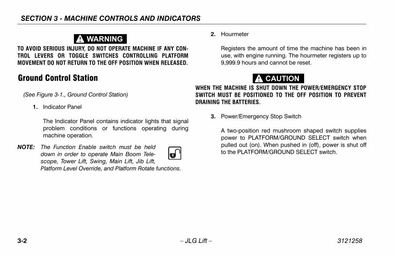
VOID SERIOUS INJURY, DO NOT OPERATE MACHINE IF ANY CON-L LEVERS OR TOGGLE SWITCHES CONTROLLING PLATFORMEMENT DO NOT RETURN TO THE OFF POSITION WHEN RELEASED.
und Control Station
ee Figure 3-1., Ground Control Station)
1. Indicator Panel
The Indicator Panel contains indicator lights that signalproblem conditions or functions operating duringmachine operation.
E: The Function Enable switch must be helddown in order to operate Main Boom Tele-scope, Tower Lift, Swing, Main Lift, Jib Lift,Platform Level Override, and Platform Rotate functions.
2. Hourm
Registuse, w9,999.
WHEN THE MACHSWITCH MUST BDRAINING THE BA
3. Power
A twopowerpulledto the
MACHINE CONTROLS AND INDICATORS
3-3
ation
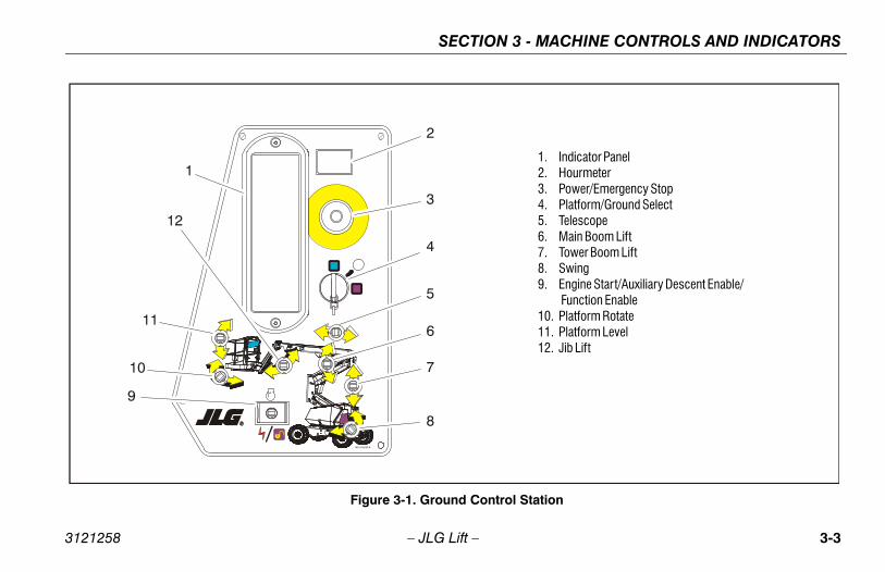
1. Indicator Panel2. Hourmeter3. Power/Emergency Stop4. Platform/Ground Select5. Telescope6. Main Boom Lift7. Tower Boom Lift8. Swing9. Engine Start/Auxiliary Descent Enable/ Function Enable10. Platform Rotate11. Platform Level12. Jib Lift
SECTION 3 -
3121258 – JLG Lift –
1001119230 A
1
2
3
4
5
6
7
8
9
10
11
12
Figure 3-1. Ground Control St
SECTION 3 - MACHINE CONTROLS AND INDICATORS
3-4 3121258
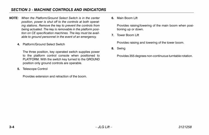
NOT oom Lift
es raising/lowering of the main boom when posi- up or down.
Boom Lift
es raising and lowering of the tower boom.
es 355 degrees non-continuous turntable rotation.
– JLG Lift –
E: When the Platform/Ground Select Switch is in the centerposition, power is shut off to the controls at both operat-ing stations. Remove the key to prevent the controls frombeing actuated. The key is removable in the platform posi-tion on CE specification machines. The key must be avail-able to ground personnel in the event of an emergency.
4. Platform/Ground Select Switch
The three position, key operated switch supplies powerto the platform control console when positioned toPLATFORM. With the switch key turned to the GROUNDposition only ground controls are operable.
5. Telescope Control
Provides extension and retraction of the boom.
6. Main B
Providtioning
7. Tower
Provid
8. Swing
Provid

MACHINE CONTROLS AND INDICATORS
3-5
THE PLATFORM LEVELING OVERRIDE FUNCTION FORLING OF THE PLATFORM. INCORRECT USE COULD CAUSE
CCUPANTS TO SHIFT OR FALL. FAILURE TO DO SO COULDEATH OR SERIOUS INJURY.
atform Leveling Override
three position switch allows the operator to adjust thetomatic self leveling system. This switch is used tojust platform level in situations such as ascending/scending a grade.
b Lift
ovides raising and lowering of the jib.
SECTION 3 -
3121258 – JLG Lift –
9. Engine Start/ Auxiliary Descent Enable /Function Enable
To start the engine, the switch must be held"UP" until the engine starts.
To use auxiliary descent enable, the switchmust be held “DOWN” for duration of func-tion use.
When the engine is running, the switchmust be held "DOWN" to enable all boomcontrols.
10. Platform Rotate
Provides rotation of the platform.
ONLY USE SLIGHT LEVETHE LOAD/ORESULT IN D
11. Pl
A auadde
12. Ji
Pr

SECTION 3 - MACHINE CONTROLS AND INDICATORS
3-6 3121258
Gro
(S
uel Level Indicator
tes the fuel level is low. The Fuel Reserve/Cut-Out will shut the engine down (or allow it start and
r an additional minute, depending upon machine before the fuel tank is emptied.
lug Indicator
tes the glow plugs are operating. After turning onn, wait until light goes out before cranking engine.
Distress Indicator
ght indicates that the JLG Control System hased an abnormal condition and a Diagnostic Trou-de has been set in the system memory. Refer torvice Manual for instructions concerning the trou-des and trouble code retrieval.
stem distress indicator light will illuminate for 2-3ds when the key is positioned to the on position toa self test.
m Overload Indicator (If Equipped)
tes the platform has been overloaded.
– JLG Lift –
und Control Indicator Panel
ee Figure 3-2., Ground Control Indicator Panel)
1. Drive and Steer Disable Indicator (If equipped)
Indicates the Drive and Steer Disable function has beenactivated.
2. High Engine Temperature Indicator
Indicates that engine coolant temperature is abnormallyhigh and service is required.
3. Low Engine Oil Pressure Indicator
Indicates that engine oil pressure is below normal andservice is required.
4. Battery Malfunction Indicator
Indicates a problem in the battery or charging circuit,and service is required.
5. Low F
IndicaSystemrun fosetup)
6. Glow P
Indicaignitio
7. System
The lidetectble Cothe Seble co
The syseconact as
8. Platfor
Indica

MACHINE CONTROLS AND INDICATORS
3-7
tor Panel
1. Drive and Steer Disable2. High Engine Coolant Temperature3. Low Engine Oil Pressure4. Battery Malfunction5. Low Fuel6. Glow Plug7. System Distress8. Platform Overload
SECTION 3 -
3121258 – JLG Lift –
1
2
3
4 5
6
7
8
Figure 3-2. Ground Control Indica
SECTION 3 - MACHINE CONTROLS AND INDICATORS
3-8 3121258
Pla
(S
TO ATROMOVWHE
PLATFORM LEVELING OVERRIDE FUNCTION FOR OF THE PLATFORM. INCORRECT USE COULD CAUSEANTS TO SHIFT OR FALL. FAILURE TO DO SO COULD OR SERIOUS INJURY.
m Leveling Override
e position switch allows the operator to adjust theatic self leveling system. This switch is used to platform level in situations such as ascending/nding a grade.
-type HORN switch supplies electrical power to ible warning device when pressed.
/Emergency Stop Switch
position red mushroom shaped switch furnishes to PLATFORM Controls when pulled out (on).pushed in (off), power is shut off to the platformns.
– JLG Lift –
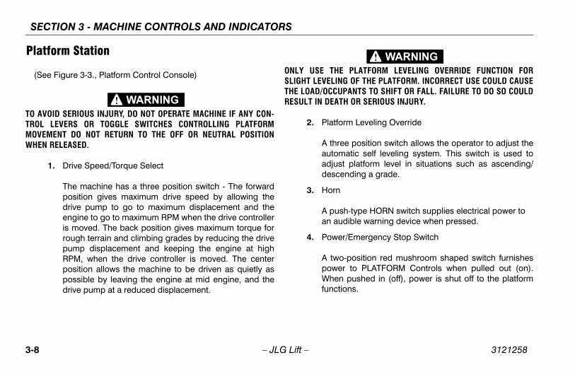
tform Station
ee Figure 3-3., Platform Control Console)
VOID SERIOUS INJURY, DO NOT OPERATE MACHINE IF ANY CON-L LEVERS OR TOGGLE SWITCHES CONTROLLING PLATFORMEMENT DO NOT RETURN TO THE OFF OR NEUTRAL POSITIONN RELEASED.
1. Drive Speed/Torque Select
The machine has a three position switch - The forwardposition gives maximum drive speed by allowing thedrive pump to go to maximum displacement and theengine to go to maximum RPM when the drive controlleris moved. The back position gives maximum torque forrough terrain and climbing grades by reducing the drivepump displacement and keeping the engine at highRPM, when the drive controller is moved. The centerposition allows the machine to be driven as quietly aspossible by leaving the engine at mid engine, and thedrive pump at a reduced displacement.
ONLY USE THE SLIGHT LEVELINGTHE LOAD/OCCUPRESULT IN DEATH
2. Platfor
A threautomadjustdesce
3. Horn
A pushan aud
4. Power
A two-powerWhen functio

MACHINE CONTROLS AND INDICATORS
3-9
1001107677 A
1702565 B
1702567 B
1705170 A
765
8910
11. Jib Lift12. Tower Boom Lift13. Platform Rotate14. Function Speed Control15. Main Lift/Swing Controller
sole
SECTION 3 -
3121258 – JLG Lift –
1702676 D
1702566 B
1 2 3 4
1112131415
1. Drive Speed/Torque Select2. Platform Leveling Override3. Horn4. Power/Emergency Stop5. Start/Auxiliary Descent Enable
6. Fuel Select7. Drive Orientation Override8. Drive/Steer9. Telescope10. Lights
Figure 3-3. Platform Control Con

SECTION 3 - MACHINE CONTROLS AND INDICATORS
3-1 3121258
rientation Override
the boom is swung over the rear tires or further indirection, the Drive Orientation indicator will illumi-hen the drive function is selected. Push and
e the switch, and within 3 seconds move theteer control to activate drive or steer. Before driv-
cate the black/white orientation arrows on bothassis and the platform controls. Move the drivels in a direction matching the directional arrows.
rate the Drive joystick, pull up on the locking ringhe handle.
ve joystick is spring loaded and will automaticallyo neutral (off) position when released.
teer
forward to drive forward, pull back to drive ine. Steering is accomplished via a thumb-activated switch on the end of the steer handle.
ope
es extension and retraction of the main boom.
0 – JLG Lift –
5. Start/Auxiliary Descent Enable
When pushed forward, the switch energizes the startermotor to start the engine.
When pushed back, it energizes Auxiliary DescentEnable which allows the boom and jib to be lowered inthe event of engine malfunction. Gravity is used to con-trol valves and lower the booms and jib. The functionsthat can be operated with this control are:
• Main Lift Down
• Tower Lift Down
• Jib Lift Down
6. Fuel Select (Dual Fuel Engine Only) (If Equipped)
Moving the switch to the appropriate position selectsgasoline or liquid propane fuel.
7. Drive O
When either nate wreleasDrive/Sing, lothe chcontro
NOTE: To opebelow t
NOTE: The Drireturn t
8. Drive/S
Push reversrocker
9. Telesc
Provid

MACHINE CONTROLS AND INDICATORS
3-11
operate the Main Boom Lift/Swing joystick, pull up on locking ring below the handle.
e Main Boom Lift/Swing joystick is spring loaded andl automatically return to neutral (off) position wheneased.
ain Lift/Swing Controller
ovides main lift and swing. Push forward to lift up, pullckward to boom down. Move right to swing right,
ove left to swing left. Moving the joystick activatesitches to provide the functions selected.
SECTION 3 -
3121258 – JLG Lift –
10. Lights (If Equipped)
This switch operates the chassis lights if the machine isso equipped.
11. Jib Lift
Provides for raising or lowering of the jib by positioningup/down.
12. Tower Boom Lift
Provides for raising and lowering of tower boom whenpositioned up or down.
13. Platform Rotate
Provides rotation of the platform when positioned to theright or left.
14. Function Speed Control
This control affects the speed of telescope, tower lift andjib lift. Turning the knob all the way counterclockwiseuntil it clicks puts drive, tower lift and swing into creepmode.
NOTE: To the
NOTE: Thwilrel
15. M
Prbamsw

SECTION 3 - MACHINE CONTROLS AND INDICATORS
3-1 3121258
Pla
(S
NOT
rm Warning Light and Alarm
d illuminator indicates that the chassis is on a An alarm will also sound when the chassis is on aand the boom is out of transport position. If litboom is out of transport position, lower to belowntal then reposition machine so that it is level continuing operation. If the boom is above hori- and the machine is on a slope, the tilt alarm warn-ht will illuminate and an alarm will sound and is automatically activated.
LIGHT IS ILLUMINATED WHEN BOOM IS RAISED ORACT AND LOWER TO BELOW HORIZONTAL THENHINE SO THAT IT IS LEVEL BEFORE EXTENDING
G BOOM ABOVE HORIZONTAL.
Tilt Angle Market
3° CE & Australia
5° ANSI, CSA & Japan
2 – JLG Lift –
tform Control Indicator Panel
ee Figure 3-4., Platform Control Indicator Panel)
E: The indicator lights will illuminate for approximately 1 sec-ond when the key is positioned to the on position to act asa self test.
1. AC Generator (If Equipped)
Indicates the generator is in operation.
2. Platform Overload Indicator (If Equipped)
Indicates the platform has been overloaded.
3. Tilt Ala
This reslope.slope when horizobeforezontaling ligCREEP
IF TILT WARNINGEXTENDED, RETRREPOSITION MACBOOM OR RAISIN

MACHINE CONTROLS AND INDICATORS
3-13
1001107853 C
4
6
5
78
7. Creep8. System Distress9. Drive Orientation
ator Panel
SECTION 3 -
3121258 – JLG Lift –
1 2 3
9
1. AC Generator2. Platform Overload3. Tilt
4. Glow Plug/Wait to Start5. Enable/Footswitch6. Fuel Level
Figure 3-4. Platform Control Indic

SECTION 3 - MACHINE CONTROLS AND INDICATORS
3-1 3121258
TO ATHE
FOOSWITOM
evel Indicator
tes the level of fuel in the tank.
Speed Indicator
the Function Speed Control is turned to the creepn, the indicator acts as a reminder that all func-re set to the slowest speed. The light flashes if thel system puts the machine into creep speed and on continuously if the operator selects creep
.
4 – JLG Lift –
4. Glow Plug/Wait to Start Indicator
Indicates the glow plugs are operating. After turning onignition, wait until light goes out before starting engine.
5. Enable Indicator/Footswitch
To operate any function, the footswitch must bedepressed and the function selected within seven sec-onds. The enable indicator shows that the controls areenabled. If a function is not selected within seven sec-onds, or if a seven second lapse between ending onefunction and beginning the next function, the enablelight will go out and the footswitch must be released anddepressed again to enable the controls.
Releasing the footswitch removes power from all con-trols and applies the drive brakes.
VOID SERIOUS INJURY, DO NOT REMOVE, MODIFY OR DISABLE FOOTSWITCH BY BLOCKING OR ANY OTHER MEANS.
TSWITCH MUST BE ADJUSTED IF FUNCTIONS ACTIVATE WHENTCH ONLY OPERATES WITHIN LAST 1/4" OF TRAVEL, TOP OR BOT-.
6. Fuel L
Indica
7. Creep
When positiotions acontrowill bespeed

MACHINE CONTROLS AND INDICATORS
3-15
rive Orientation Indicator
hen the boom is swung beyond the rear drive tires orrther in either direction, the Drive Orientation indicatorill illuminate when the drive function is selected. This issignal for the operator to verify that the drive control ising operated in the proper direction (i.e. controlsversed situations).
SECTION 3 -
3121258 – JLG Lift –
8. System Distress Indicator
The light indicates that the JLG Control System hasdetected an abnormal condition and a Diagnostic Trou-ble Code has been set in the system memory. Refer tothe Service Manual for instructions concerning the trou-ble codes and trouble code retrieval.
9. D
Wfuwa bere

SECTION 3 - MACHINE CONTROLS AND INDICATORS
3-1 3121258
6 – JLG Lift –NOTES:

SECTION 4 - MACHINE OPERATION
4-1
PERATIONimary operator control station is in the platform. Fromntrol station, the operator can drive and steer the
ne in both forward and reverse directions. The opera- raise or lower the boom or swing the boom to the leftt. Standard boom swing is 355 degree non-continu-he machine has a Ground Control Station which wille the Platform Control Station. Ground Controls oper-om Lift and Swing, and are to be used in an emer- to lower the platform to the ground should theor in the platform be unable to do so.
3121258 – JLG Lift –
SECTION 4. MACHINE O
4.1 DESCRIPTIONThis machine is a self-propelled hydraulic personnel liftequipped with a work platform on the end of an elevatingand rotating boom.
The prthis comachitor canor righous. Toverridate Bogencyoperat
SECTION 4 - MACHINE OPERATION
4-2 3121258
4.2
Ca
Sta
TO MAC
E OPERATION
tarting should always be performed from the Control station.
cedure
TO START PROMPTLY, DO NOT CRANK FOR AN. SHOULD ENGINE FAIL TO START AGAIN, ALLOWOL OFF” FOR 2-3 MINUTES. IF ENGINE FAILS AFTER
PTS, REFER TO ENGINE MAINTENANCE MANUAL.
engines only: After turning on ignition, operatorait until glow plug indicator light goes out beforeg engine.
key of SELECT switch to GROUND. PositionR/EMERGENCY STOP switch to ON, then pushGINE START switch until engine starts.
TO WARM-UP FOR A FEW MINUTES AT LOW SPEEDG ANY LOAD.
– JLG Lift –
BOOM OPERATING CHARACTERISTICS AND LIMITATIONS
pacities
Raising boom above horizontal with or without any load inplatform, is based on the following criteria:
1. Machine is positioned on a smooth, firm and level sur-face.
2. Load is within manufacturers rated design capacity.
3. All machine systems are functioning properly.
4. Machine is as originally equipped from JLG.
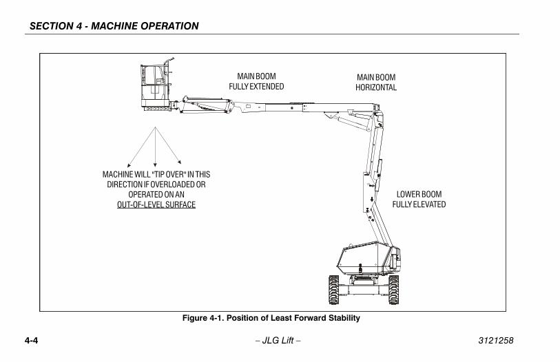
bilityMachine stability is based on two (2) conditions which arecalled FORWARD and BACKWARD stability. The machine’sposition of least FORWARD stability is shown in Figure 4-1.,and its position of least BACKWARD stability is shown in Fig-ure 4-2.
AVOID FORWARD OR BACKWARD TIPPING, DO NOT OVERLOADHINE OR OPERATE THE MACHINE ON AN OUT-OF-LEVEL SURFACE.
4.3 ENGIN
NOTE: Initial sGround
Starting Pro
IF ENGINE FAILSEXTENDED TIMESTARTER TO “COSEVERAL ATTEM
NOTE: Diesel must wcrankin
1. Turn POWEthe EN
ALLOW ENGINE BEFORE APPLYIN

SECTION 4 - MACHINE OPERATION
4-3
to Engine Manufacturer’s manual for detailed informa-
erve / Shut-Off System (Gas or Diesel Only)el Shutoff System senses when the fuel level is gettingd automatically shuts the engine down before the fuel emptied.
ding upon machine setup, the machine will eitherhe engine shut down until the fuel tank is refilled or thetor will be able to restart and run the engine for annal minute. After 1 minute, the engine will shut off for a
d time and the machine will return to the engine shut-mode until the fuel tank is refilled.
3121258 – JLG Lift –
2. After engine has had sufficient time to warm up, shutengine off.
3. Turn SELECT switch to PLATFORM.
4. From Platform, pull POWER/EMERGENCY STOP switchout, then push the ENGINE START switch until enginestarts.
NOTE: Footswitch must be in released (up) position beforestarter will operate. If starter operates with footswitch inthe depressed position, DO NOT OPERATE MACHINE.
Shutdown Procedure
IF AN ENGINE MALFUNCTION CAUSES AN UNSCHEDULED SHUT-DOWN, DETERMINE THE CAUSE AND CORRECT IT BEFORE RESTART-ING THE ENGINE.
1. Remove all load and allow engine to operate at lowspeed for 3-5 minutes; this allows further reduction ofinternal engine temperature.
2. Push POWER/EMERGENCY STOP switch in.
3. Turn Platform/Ground Select switch to Off.
Refer tion.
Fuel ResEngines
The Fulow antank is
Depenkeep toperaadditiosecondown
SECTION 4 - MACHINE OPERATION
4-4 3121258
ability
LOWER BOOMFULLY ELEVATED
MAIN BOOMHORIZONTAL
– JLG Lift –
Figure 4-1. Position of Least Forward St
MAIN BOOMFULLY EXTENDED
MACHINE WILL "TIP OVER" IN THISDIRECTION IF OVERLOADED OR
OPERATED ON ANOUT-OF-LEVEL SURFACE

SECTION 4 - MACHINE OPERATION
4-5
d Stability
LOWER BOOMFULLY ELEVATED
MACHINE WILL "TIP OVER" IN THISDIRECTION IF OVERLOADED OR
OPERATED ON ANOUT-OF-LEVEL SURFACE
3121258 – JLG Lift –
.
Figure 4-2. Position of Least Backwar
MAIN BOOM FULLY ELEVATEDAND FULLY RETRACTED
PLATFORM ROTATED90 DEGREES

SECTION 4 - MACHINE OPERATION
4-6 3121258
4.3
S
NOT
ITH BOOM OUT OF TRANSPORT MODE EXCEPT ON AND LEVEL SURFACE.
F TRAVEL CONTROL OR “TIP OVER”, DO NOT DRIVEDES EXCEEDING THOSE SPECIFIED IN THE OPERAT-NS SECTION OF THIS MANUAL.
SIDESLOPES WHICH EXCEED 5 DEGREES.
AUTION WHEN DRIVING IN REVERSE AND AT ALL PLATFORM IS ELEVATED.
, LOCATE THE BLACK/WHITE ORIENTATION ARROWSASSIS AND THE PLATFORM CONTROLS. MOVE THE
S IN A DIRECTION MATCHING THE DIRECTIONAL
– JLG Lift –
TRAVELING (DRIVING)
ee Figure 4-3., Grade and Side Slopes
E: Refer to the Operating Specifications table for Gradeabil-ity and Sideslope ratings.
All ratings for Gradeability and Sideslope are based uponthe machine’s boom being in the stowed position, fullylowered, and retracted.
Traveling is limited by two factors:
1. Gradeability, which is the percent of grade of the incline the machine can climb.
2. Sideslope, which is the angle of the slope the machine can be driven across.
DO NOT DRIVE WSMOOTH, FIRM A
TO AVOID LOSS OMACHINE ON GRAING SPECIFICATIO
DO NOT DRIVE ON
USE EXTREME CTIMES WHEN THE
BEFORE DRIVINGON BOTH THE CHDRIVE CONTROLARROWS.

SECTION 4 - MACHINE OPERATION
4-7
SIDE SLOPE
opes
3121258 – JLG Lift –
GRADE
LEVEL
Figure 4-3. Grade and Side Sl

SECTION 4 - MACHINE OPERATION
4-8 3121258
Tra
4.4
ORM
PLATFORM LEVELING OVERRIDE FUNCTION FOR OF THE PLATFORM. INCORRECT USE COULD CAUSEANTS TO SHIFT OR FALL. FAILURE TO DO SO COULD OR SERIOUS INJURY.
el Adjustmently Level Up or Down - Position the Platform/Levelitch Up or Down and hold until the desired plat-on is obtained.
tationhe platform to the left or right, use the Platformtrol switch to select the direction and hold until
sition is reached.
– JLG Lift –
veling Forward and Reverse3. At Platform Controls, pull out Emergency Stop switch,
start engine, and activate footswitch.
4. Position Drive controller to FORWARD or REVERSE as desired.
This machine is equipped with a Drive Orientation Indicator.The yellow light on the platform control console indicatesthat the boom is swung beyond the rear drive tires and themachine may Drive/Steer in the opposite direction from themovement of the controls. If the indicator is illuminated,operate the Drive function in the following manner:
1. Match the black and white direction arrows on both plat-form control panel and the chassis to determine the direction the machine will travel.
2. Push and release the Drive Orientation Override switch. Within 3 seconds, slowly move the Drive control toward the arrow matching the intended direction of machine travel. The indicator light will flash during the 3 second interval until the drive function is selected.
STEERINGPosition thumb switch on Drive/Steer controller to RIGHT forsteering right, or to LEFT for steering left.
4.5 PLATF
ONLY USE THE SLIGHT LEVELINGTHE LOAD/OCCUPRESULT IN DEATH
Platform LevTo manualcontrol swform positi
Platform RoTo rotate tRotate condesired po

SECTION 4 - MACHINE OPERATION
4-9
ERIOUS INJURY, DO NOT OPERATE MACHINERY IF ANYEVER OR TOGGLE SWITCH CONTROLLING PLATFORMDOES NOT RETURN TO THE ‘OFF’ OR NEUTRAL POSITIONSED.
COLLISION AND INJURY IF PLATFORM DOES NOT STOPNTROL SWITCH OR LEVER IS RELEASED, REMOVE FOOTWITCH OR USE EMERGENCY STOP SWITCH TO STOP THE
the Boom
ing boom, use Swing control to select Right or Lefton.
nd Lowering the Tower Boome or lower the Tower Boom, position Tower Boom Lift to Up or Down until desired height is reached.
3121258 – JLG Lift –
4.6 BOOM
A RED TILT WARNING LIGHT IS LOCATED ON THE CONTROL CONSOLEWHICH LIGHTS WHEN THE CHASSIS IS ON AN EXCESSIVE SLOPE. DONOT SWING OR RAISE BOOM ABOVE HORIZONTAL WHEN LIGHT IS LIT.
DO NOT DEPEND ON TILT ALARM AS A LEVEL INDICATOR FOR THECHASSIS. TILT ALARM INDICATES CHASSIS IS ON AN EXCESSIVESLOPE (3 DEGREE OR GREATER ON CE & AUSTRALIA SPEC MACHINES,5 DEGREE OR GREATER ON ANSI, CSA, & JAPAN SPEC MACHINES).CHASSIS MUST BE LEVEL BEFORE SWINGING, OR RAISING BOOMABOVE HORIZONTAL OR DRIVING WITH THE BOOM ELEVATED.
TO AVOID TIP OVER IF RED TILT WARNING LIGHT LIGHTS WHEN BOOMIS RAISED ABOVE HORIZONTAL, LOWER PLATFORM TO GROUNDLEVEL. THEN REPOSITION MACHINE SO THAT CHASSIS IS LEVELBEFORE RAISING BOOM.
TRAVELING WITH BOOM BELOW HORIZONTAL IS PERMITTED ONGRADES AND SIDE SLOPES SPECIFIED IN THE OPERATING SPECIFICA-TIONS SECTION OF THIS MANUAL.
TO AVOID SCONTROL LMOVEMENT WHEN RELEA
TO AVOID AWHEN A COFROM FOOTSMACHINE.
Swinging
To swdirecti
Raising aTo raisswitch

SECTION 4 - MACHINE OPERATION
4-1 3121258
4.7
4.8
IT ISWITTAK
Ch
om LP Gas to Gasoline
ngine operating on LP under a no-load condition,n FUEL SELECT switch at Platform Control Sta- GASOLINE position.
hand valve on LP gas supply tank by turningise.
DOWN AND PARK
nd Park 4-4.
ures to shut down and park the machine are as
achine to a reasonably well protected area.
boom is lowered over rear drive axle.
own Emergency Stop at Platform Controls.
own Emergency Stop at Ground Controls. Posi-atform/Ground Select switch to center OFF.
ssary, cover Platform Controls to protect instruc-lacards, warning decals, and operating controlsostile environment.
0 – JLG Lift –
FUNCTION SPEED CONTROLThis control affects the speed of telescope, tower boom liftand jib lift. Turning the knob all the way counterclockwiseuntil it clicks puts drive, main lift, platform rotate, and swinginto creep mode.
DUAL FUEL SYSTEM (GAS ENGINE ONLY)The dual fuel system enables the standard gasoline engineto run on either gasoline or LP gas.
POSSIBLE TO SWITCH FROM ONE FUEL SOURCE TO THE OTHERHOUT ALLOWING THE ENGINE TO STOP. EXTREME CARE MUST BEEN AND THE FOLLOWING INSTRUCTIONS MUST BE FOLLOWED.
anging From Gasoline to LP Gas
1. Start engine from Ground Control Station.
2. Open hand valve on LP gas supply tank by turningcounterclockwise.
3. While engine is operating on GASOLINE under a no-load condition, place FUEL SELECT switch at PlatformControl to LP position.
Changing Fr
1. With epositiotion to
2. Close clockw
4.9 SHUT
Shut Down aSee Figure
The procedfollows:
1. Drive m
2. Ensure
3. Shut d
4. Shut dtion Pl
5. If necetion pfrom h

SECTION 4 - MACHINE OPERATION
4-11
n
3121258 – JLG Lift –
Figure 4-4. Stowed Positio
SECTION 4 - MACHINE OPERATION
4-1 3121258
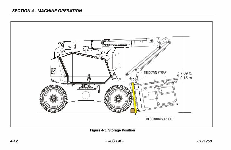
7.09 ft.2.15 m
BLOCKING/SUPPORT
TIE DOWN STRAP
2 – JLG Lift –
Figure 4-5. Storage Position

SECTION 4 - MACHINE OPERATION
4-13
TING AND TIE DOWNigure 4-6.)
fer to the Serial Number Plate, refer to the Specifica-ns section of this manual, or weigh the individual unit find out the Gross Vehicle Weight.
ace the boom in the stowed position.
move all loose items from the machine.
operly adjust the rigging to prevent damage to theachine and so the machine remains level.
SPORTING THE MACHINE IN THE STOWED POSITION, THE BE FULLY LOWERED INTO THE BOOM REST.
ace the boom in the stowed position or storage posi-n.
move all loose items from the machine.
cure the chassis and the platform using straps orains of adequate strength.
3121258 – JLG Lift –
Storage Position(See Figure 4-5.)
The procedures to place the machine in the storage positionis as follows:
1. From the ground control station, raise the boom at least to the elevation shown in Figure 4-5. The boom must be raised to prevent the platform basket from hitting the ground during this procedure.
THE JLG CONTROL SYSTEM WILL SET A DIAGNOSTIC TROUBLE CODETO SIGNIFY THE JIB IS BEING PLACED IN THE STORAGE POSITION.
2. Using the jib lift control, lower the jib until the platform is in the position shown.
THE PLATFORM BASKET MUST NOT BE IN CONTACT WITH THEGROUND, BLOCKING, OR ANY TIE DOWN EQUIPMENT.
3. Place blocking under the platform support, lower the platform support down onto the blocking, and tie it down as shown in Figure 4-5.
4.10 LIF(See F
Lifting1. Re
tioto
2. Pl
3. Re
4. Prm
Tie Down
WHEN TRANBOOM MUST
1. Pltio
2. Re
3. Sech

SECTION 4 - MACHINE OPERATION
4-1 3121258
.4”/1.10m
.4”/1.05m
340AJ
1001119576 B
art
4 – JLG Lift –
A 43B 41
CL
Figure 4-6. Lifting and Tie Down Ch

SECTION 4 - MACHINE OPERATION
4-15
21
et 1 of 10
3121258 – JLG Lift –
18
6
61414
Figure 4-7. Decal Location She

SECTION 4 - MACHINE OPERATION
4-1 3121258
8
34 3513 1431
36
7 73039
24
26
12
10
6 – JLG Lift –
18
1435
Figure 4-8. Decal Location Sheet 2 of

SECTION 4 - MACHINE OPERATION
4-17
AUS
824 4211
heet 3 of 10
3121258 – JLG Lift –
CEANSI
824
43
12
82411
Figure 4-9. Decal Location S
SECTION 4 - MACHINE OPERATION
4-1 3121258
11
26
10
8 – JLG Lift –
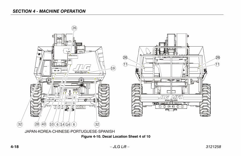
3232 610 614 1443
19
26
28
JAPAN-KOREA-CHINESE-PORTUGUESE-SPANISH
11
26
Figure 4-10. Decal Location Sheet 4 of

SECTION 4 - MACHINE OPERATION
4-19
32610 614 1427
26
19
AUSTRALIA
heet 5 of 10
3121258 – JLG Lift –
26
CE3232 610 614 1427 19
32
Figure 4-11. Decal Location S

SECTION 4 - MACHINE OPERATION
4-2 3121258
4126
19
32610 614 1443
FRENCH
t 6 of 10
0 – JLG Lift –
32 28
ANSI
3232 610 614 1428 36
4126
19
Figure 4-12. Decal Location Shee

SECTION 4 - MACHINE OPERATION
4-21
7 of 10
3121258 – JLG Lift –
4747
Figure 4-13. Decal Location Sheet

SECTION 4 - MACHINE OPERATION
4-2 3121258
32
32
1111
27
f 10
2 – JLG Lift –
4
32
3232
37
1
1617
20
19
2038
23
25
27
37
45
44
32
Figure 4-14. Decal Location Sheet 8 o

SECTION 4 - MACHINE OPERATION
4-23
ORTUGUESE-JAPANESE
4
9
t 9 of 10
3121258 – JLG Lift –
ANSI-SPANISH-FRENCH-KOREAN-CHINESE-P
5
15
33
34
35 3513
14
14
26
7
12
46
7
29
Figure 4-15. Decal Location Shee
SECTION 4 - MACHINE OPERATION
4-2 3121258
4
5
9
15
14
of 10
4 – JLG Lift –
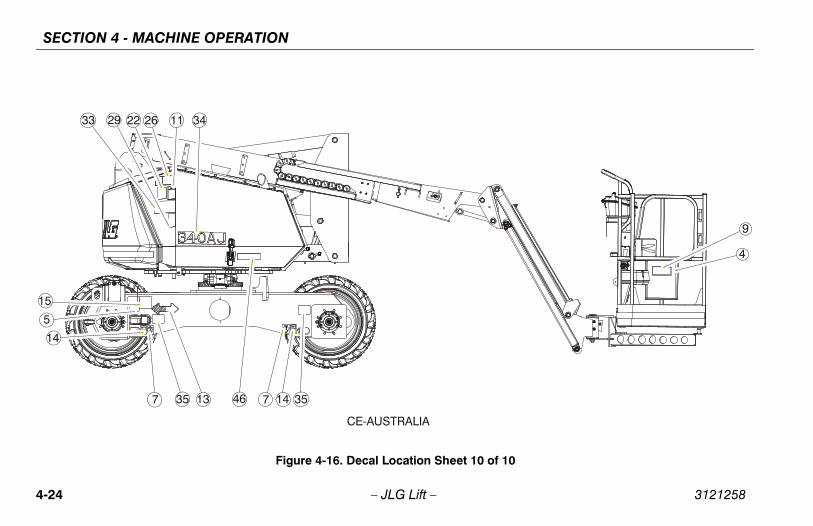
CE-AUSTRALIA
222933 3426
35 3513 147467
11
Figure 4-16. Decal Location Sheet 10

SECTION 4 - MACHINE OPERATION
4-25
French1001119736-C
Chinese1001119737-C
Portuguese1001119738-C
Spanish1001119739-C
- - - - - - - -
- - - - - - - -
- - - - - - - -
- - - - - - - -
1700584 1700584 1700584 1700584
1701500 1701500 1701500 1701500
1701499 1701499 1701499 1701499
1701504 1701504 1701504 1701504
1701509 1701509 1701509 1701509
1001113169 1001113168 1001113170 1001113171
1703948 1703949 1703952 1703947
1703942 1703943 1705903 1703941
1701642 1701642 1701642 1701642
1702300 1702300 1702300 1702300
1702631 1702631 1702631 1702631
- - - - - - - -
- - - - - - - -
- - - - - - - -
- - - - - - - -
3121258 – JLG Lift –
Item # ANSI1001119732-C
CE1001115783-C
Australia1001119733-C
Japan1001119734-C
Korea1001119735-C
1 - - - - - - - - - -
2 - - - - - - - - - -
3 - - - - - - - - - -
4 - - - - - - - - - -
5 1700584 1700584 1700584 1700584 1700584
6 1701500 1701500 1701500 1701500 1701500
7 1701499 1701499 1701499 1701499 1701499
8 1701504 1701504 1701504 1701504 1701504
9 1701509 1701509 1701509 1701509 1701509
10 1702391 1701517 1701517 1001113166 1001113509
11 1703804 1701518 1701518 1703950 1703951
12 1703953 - - - - 1703944 1703945
13 1701642 1701642 1701642 1701642 1701642
14 1702300 1702300 1702300 1702300 1702300
15 1702631 1702631 1702631 1702631 1702631
16 - - - - - - - - - -
17 - - - - - - - - - -
18 - - - - - - - - - -
19 - - - - - - - - - -

SECTION 4 - MACHINE OPERATION
4-2 3121258
04277 1704277 1704277 1704277
04412 1704412 1704412 1704412
- - - - - - - -
03924 1703925 1703928 1703923
05347 1705348 1705349 1705917
03984 1703982 1703985 1703983
03936 1703937 1703940 1703935
07055 1707060 1707134 1707056
07047 1707044 1707133 1707049
- - - - - - - -
- - - - - - - -
- - - - - - - -
- - - - - - - -
1119576 1001119576 1001119576 1001119576
1119578 1001119578 1001119578 1001119578
1119580 1001119580 1001119580 1001119580
- - - - - - - -
04000 1705968 1704002 1704001
05429 1705430 1001113680 1705910
- - - - - - - -
Ite rench119736-C
Chinese1001119737-C
Portuguese1001119738-C
Spanish1001119739-C
6 – JLG Lift –
20 1704277 1704277 1704277 1704277 1704277 17
21 1704412 1704412 1704412 1704412 1704412 17
22 1703797 1705084 - - - - - -
23 1703798 1705921 1705921 1703926 1703927 17
24 - - 1705822 1705822 1705344 1705345 17
25 1703805 1705828 1705828 1703980 1703981 17
26 1701645 1705961 1705961 1703938 1703939 17
27 1707013 1705978 1705978 1707059 1707058 17
28 - - - - - - 1707054 1707042 17
29 - - - - - - - - - -
30 - - - - - - - - - -
31 - - - - - - - - - -
32 - - - - - - - - - -
33 1001119576 1001119576 1001119576 1001119576 1001119576 100
34 1001119578 1001119578 1001119578 1001119578 1001119578 100
35 1001119580 1001119580 1001119580 1001119580 1001119580 100
36 - - - - - - - - - -
37 1702868 - - - - - - 1705969 17
38 1705351 - - - - 1705426 1705427 17
39 - - - - - - - - - -
m # ANSI1001119732-C
CE1001115783-C
Australia1001119733-C
Japan1001119734-C
Korea1001119735-C
F1001
SECTION 4 - MACHINE OPERATION
4-27
- - - - - - - -
- - - - - - - -
- - 1001112551 - - - -
1001120009 1001120009 1001120009 1001120009
1001120010 1001120010 1001120010 1001120010
1001120004 1001120281 1001120282 1001120283
1001119981 1001119981 1001119981 1001119981
1701529 1701529 1701529 1701529
French1001119736-C
Chinese1001119737-C
Portuguese1001119738-C
Spanish1001119739-C
3121258 – JLG Lift –
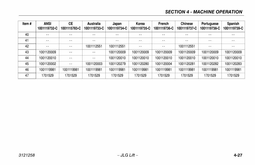
40 - - - - - - - - - -
41 - - - - - - - - - -
42 - - - - 1001112551 1001112551 - -
43 1001120009 - - - - 1001120009 1001120009
44 1001120010 - - - - 1001120010 1001120010
45 1001120002 - - 1001120003 1001120279 1001120280
46 1001119981 1001119981 1001119981 1001119981 1001119981
47 1701529 1701529 1701529 1701529 1701529
Item # ANSI1001119732-C
CE1001115783-C
Australia1001119733-C
Japan1001119734-C
Korea1001119735-C

SECTION 4 - MACHINE OPERATION
4-2 3121258
8 – JLG Lift –NOTES:
SECTION 5 - EMERGENCY PROCEDURES
5-1
ROCEDURES
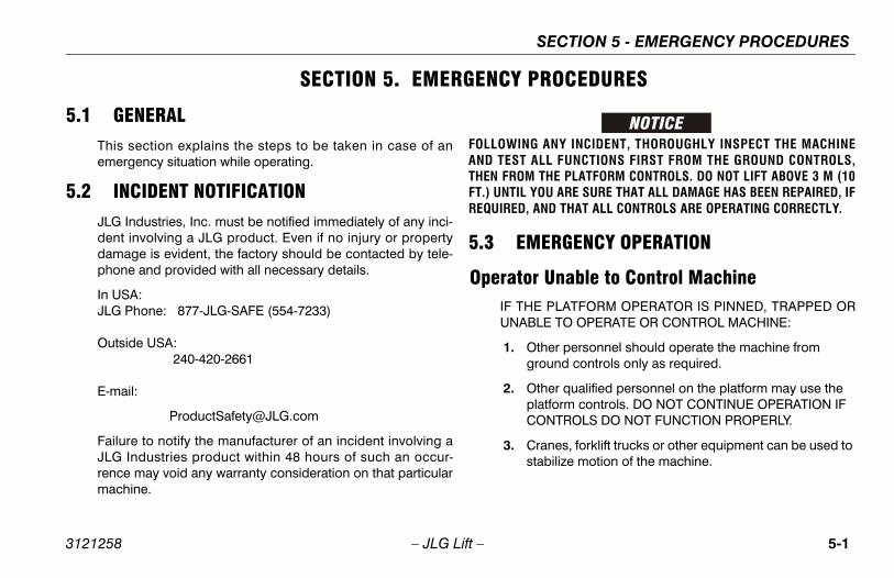
ANY INCIDENT, THOROUGHLY INSPECT THE MACHINELL FUNCTIONS FIRST FROM THE GROUND CONTROLS,THE PLATFORM CONTROLS. DO NOT LIFT ABOVE 3 M (10OU ARE SURE THAT ALL DAMAGE HAS BEEN REPAIRED, IFND THAT ALL CONTROLS ARE OPERATING CORRECTLY.
ERGENCY OPERATION
Unable to Control Machine PLATFORM OPERATOR IS PINNED, TRAPPED OR
LE TO OPERATE OR CONTROL MACHINE:
ther personnel should operate the machine from ound controls only as required.
ther qualified personnel on the platform may use the atform controls. DO NOT CONTINUE OPERATION IF ONTROLS DO NOT FUNCTION PROPERLY.
ranes, forklift trucks or other equipment can be used to abilize motion of the machine.
3121258 – JLG Lift –
SECTION 5. EMERGENCY P
5.1 GENERALThis section explains the steps to be taken in case of anemergency situation while operating.
5.2 INCIDENT NOTIFICATIONJLG Industries, Inc. must be notified immediately of any inci-dent involving a JLG product. Even if no injury or propertydamage is evident, the factory should be contacted by tele-phone and provided with all necessary details.
In USA:JLG Phone: 877-JLG-SAFE (554-7233) Outside USA: 240-420-2661
E-mail:
Failure to notify the manufacturer of an incident involving aJLG Industries product within 48 hours of such an occur-rence may void any warranty consideration on that particularmachine.
FOLLOWINGAND TEST ATHEN FROM FT.) UNTIL YREQUIRED, A
5.3 EM
OperatorIF THEUNAB
1. Ogr
2. OplC
3. Cst

SECTION 5 - EMERGENCY PROCEDURES
5-2 3121258
Pla
5.4
R
ssary to raise the jib in order to properly performry descent procedure, use the following proce-
he ground control console, place the Platform/d Select switch in the Ground position.
t the Power/Emergency Stop control.
own the Auxiliary Descent Enable Switch, hold up lift control switch and operate the hand pump d next to the hydraulic tank to raise the jib.
AL SWING OVERRIDE
ing override is used to manually swing the boomassembly in the event of a total power failure when positioned over a structure or obstacle. To oper-l swing override, proceed as follows:
a 7/8 inch socket and ratchet wrench, locate nutng worm gear on left side of machine.
wrench on nut and ratchet in the directiond.
– JLG Lift –
tform or Boom Caught OverheadIf the platform or boom becomes jammed or snagged inoverhead structures or equipment, rescue platform occu-pants prior to freeing the machine.
AUXILIARY DESCENT SYSTEM
efer to Figure 5-1., Auxiliary Descent Decal and Hand Pump.
The auxiliary descent system allows the boom and jib to belowered in the event of primary power (engine power) loss.This system uses electrically powered solenoid valves andthe force of gravity to lower the booms and jib. The followingfunctions are included in this system and will operate nor-mally if the engine is not running and the auxiliary powerswitch has been activated.
• Main Lift Down
• Tower Lift Down
• Jib Lift Down
1. From the ground control console, place the Platform/Ground Select switch in the Ground position.
2. Pull out the Power/Emergency Stop control.
3. Hold down the Auxiliary Descent Enable Switch and the control switch for the desired function.
If it is necethe auxiliadure.
1. From tGroun
2. Pull ou
3. Hold dthe jiblocate
5.5 MANU
The manual swand turntable the platform isate the manua
1. Using on swi
2. Install desire

SECTION 5 - EMERGENCY PROCEDURES
5-3
HANDPUMP
Hand Pump
3121258 – JLG Lift –
1001127549 A
+
+
1 2
3
+
1 2
3
PUMPHANDLE4
4 5
Figure 5-1. Auxiliary Descent Decal and

SECTION 5 - EMERGENCY PROCEDURES
5-4 3121258
5.6
Toindsu
THEALL
g machine, complete the following procedure:
n machine on a firm level surface.
wheels securely.
age the mechanical release on both drive hubssening, completely reversing, and tightening thelts on each hub.
e chocks from wheels as desired.
– JLG Lift –
EMERGENCY TOWING PROCEDURES
wing this machine is prohibited. However, provisions for mov-g the machine have been incorporated. The following proce-ures are to be used ONLY for emergency movement to aitable maintenance area.
ALLOWABLE TOWING SPEED IS 1.9 MPH (3 KPH). THE MAXIMUMOWABLE TOWING DISTANCE IS 0.6 MILES (1 KM).
1. Chock wheels securely.
2. Engage the mechanical release on both drive hubs byloosening, completely reversing, and tightening the twobolts on each hub.
3. Connect suitable equipment, remove chocks, and movemachine.
After movin
1. Positio
2. Chock
3. Disengby lootwo bo
4. Remov

FICATIONS & OPERATOR MAINTENANCE
6-1
OPERATOR MAINTENANCE
ERATING SPECIFICATIONS AND RFORMANCE DATAg Specifications
Table 6-1. Operating Specifications
nrestricted:
alia500 lbs. (227 kg)500 lbs. (230 kg)
ravel Grade, stowedradeability) see Figure 4-3.
45%
ravel Grade, stowedde Slope) see Figure 4-3.
5°
- Stowed 3.1 mph (5.0 kph)
ve Speed 0.6 mph (1.0 kph)
ine Weight - Approximate
alia9400 lbs. (4263 kg)9700 lbs. (4400 kg)
SECTION 6 - GENERAL SPECI
3121258 – JLG Lift –
SECTION 6. GENERAL SPECIFICATIONS &
6.1 INTRODUCTIONThis section of the manual provides additional necessaryinformation to the operator for proper operation and mainte-nance of this machine.
The maintenance portion of this section is intended as infor-mation to assist the machine operator to perform daily main-tenance tasks only, and does not replace the more thoroughPreventive Maintenance and Inspection Schedule includedin the Service and Maintenance Manual.
Other Publications Available:
Service and Maintenance Manual ............................ 3121259
Illustrated Parts Manual ............................................ 3121260
6.2 OPPE
Operatin
Capacity: U ANSI CE & Austr
Maximum T Position (G
Maximum T Position (Si
Drive Speed
Elevated Dri
Gross Mach ANSI CE & Austr

SECTION 6 - GENERAL SPECIFICATIONS & OPERATOR MAINTENANCE
6-2 3121258
Dim
Gr P F S N
Sy
M
atform Height 17’ 0" (5.17 m)
ch 19’ 11" (6.06 m)
6’ 4" (1.93 m)
6’ 2" (1.87 cm)
t
a33’ 9" (10.29 m)
33’ 10.5" (10.33 m)
nce 10.1" (23.7 cm)
Table 6-3. Capacities
nk (to Full Level) 20.6 Gal. (77.9 L)
25.5 oz. (0.75 L)
ould be one half full of lubricant.
Table 6-2. Dimensional Data
– JLG Lift –
ensional Data
Capacities
ound Bearing Pressureneumatic
oam Filled
olid
on-Marking Solid
59 psi (4.1 kg/cm2)64 psi (4.5 kg/cm2)70 psi (4.9 kg/cm2)81 psi (5.7 kg/cm2)
stem Voltage 12V DC
aximum Main Relief Hyd. Pressure 4060 psi (280 Bar)
Table 6-2. Dimensional Data
Turning Radius (Inside) 5’ (1.52 m)
Turning Radius (Outside) 13’ (3.96 m)
Machine Height (stowed) 6’ 7" (2 m)
Machine Height (storage) 7’ 1" (2.17 m)
Machine Length (stowed) 18’ 2" (5.52 m)
Machine Length (storage) 13’ 1" (3.98 m)
Table 6-1. Operating Specifications
Up and Over Pl
Horizontal Rea
Machine Width
Wheel Base
Platform Heigh ANSI CE & Australi
Ground Cleara
Hydraulic Oil Ta
Drive Hub*
*Drive hubs sh

FICATIONS & OPERATOR MAINTENANCE
6-3
ata
Table 6-5. Kubota D1105-E3
Liquid Cooled
ylinders 3
3.07 in. (78 mm)
3.09 in. (78.4 mm)
ement 68.5 cu. in. (1123 cm³)
n Ratio 24:1
1-2-3
24.8 hp (18.5 kW)
1200 ± 50
3000± 50
SECTION 6 - GENERAL SPECI
3121258 – JLG Lift –
Tires Engine D
Table 6-4. Tires
Size 265/50 D20 (20" x 9")
Maximum Tire Load 4800 lbs. (2177 kg)
Type Air, Foam-Filled
Size 18" x 7"
Maximum Tire Load 4800 lbs. (2177 kg)
Type Solid
Type
Number of C
Bore
Stroke
Total Displac
Compressio
Firing Order
Output
Low Idle RPM
High Idle RPM

SECTION 6 - GENERAL SPECIFICATIONS & OPERATOR MAINTENANCE
6-4 3121258
l
lic oils require anti-wear qualities at least API Ser-assification GL-3, and sufficient chemical stabilityile hydraulic system service.
es may be equipped with Mobil EAL biodegrad-d non-toxic hydraulic oil. This is a fully syntheticic oil that possesses the same anti-wear and rustion characteristics as mineral oils, but will notly affect the ground water or the environment
pilled or leaked in small amounts.
Typ
Nu
Bor
Str
Tot
Com
Firi
Ou
Low
Hig
Table 6-7. Hydraulic Oil
aulic Systemperating
erature Range
S.A.E. ViscosityGrade
° to + 180° F° to +83° C)
10W
° to + 210° F° to +99° C)
10W-20, 10W30
° to + 210° F0° to +99° C
20W-20
– JLG Lift –
Hydraulic Oi
NOTE: Hydrauvice Clfor mob
NOTE: Machinable anhydraulprotectadversewhen s
Table 6-6. GM 0.97L
e Liquid Cooled
mber of Cylinders 4
e 2.58 in. (65.5 mm)
oke 2.84 in. (72.0 mm)
al Displacement 59 cu. in. (967 cm³)
pression Ratio 8.8:1
ng Order 1-3-4-2
tput 28.6 hp (21.3 kW)
Idle RPM 1200 ± 50
h Idle RPM 3000± 50
HydrO
Temp
+0(-18
+0(-18
+50(+1

FICATIONS & OPERATOR MAINTENANCE
6-5
AMPLING
e 6-1., Oil Sampling Port.
achine is equipped with an oil sampling valve to allowification of hydraulic oil condition. Refer to the Servicel for Oil Sampling procedures.
SECTION 6 - GENERAL SPECI
3121258 – JLG Lift –
NOTE: Aside from JLG recommendations, it is not advisable tomix oils of different brands or types, as they may not con-tain the same required additives or be of comparable vis-cosities. If use of hydraulic oil other than Mobil 424 isdesired, contact JLG Industries for proper recommenda-tions.
OIL S
See Figur
This mfor verManua

SECTION 6 - GENERAL SPECIFICATIONS & OPERATOR MAINTENANCE
6-6 3121258
– JLG Lift –Figure 6-1. Oil Sampling Port
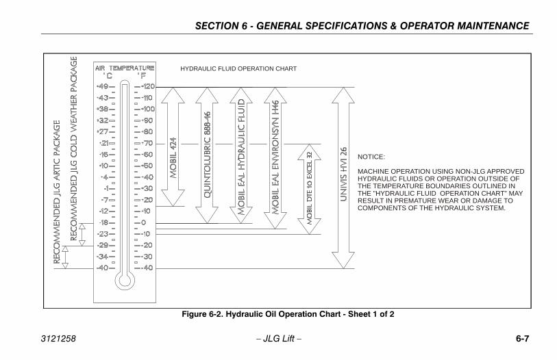
FICATIONS & OPERATOR MAINTENANCE
6-7
NOTICE:
MACHINE OPERATION USING NON-JLG APPROVEDHYDRAULIC FLUIDS OR OPERATION OUTSIDE OFTHE TEMPERATURE BOUNDARIES OUTLINED INTHE "HYDRAULIC FLUID OPERATION CHART" MAYRESULT IN PREMATURE WEAR OR DAMAGE TOCOMPONENTS OF THE HYDRAULIC SYSTEM.
rt - Sheet 1 of 2
SECTION 6 - GENERAL SPECI
3121258 – JLG Lift –
HYDRAULIC FLUID OPERATION CHART
Figure 6-2. Hydraulic Oil Operation Cha
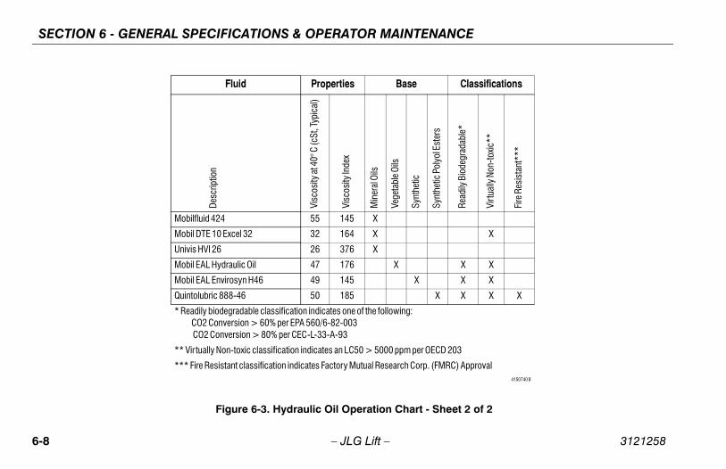
SECTION 6 - GENERAL SPECIFICATIONS & OPERATOR MAINTENANCE
6-8 3121258
heet 2 of 2
Classifications
Synt
hetic
Pol
yol E
ster
s
Read
ily B
iode
grad
able
*
Virt
ually
Non
-toxi
c**
Fire
Res
ista
nt**
*
X
X X
X X
X X X X
CD 203
MRC) Approval4150740 B
– JLG Lift –
Figure 6-3. Hydraulic Oil Operation Chart - S
Fluid Properties Base
Desc
riptio
n
Visc
osity
at 4
0° C
(cSt
, Typ
ical
)
Visc
osity
Inde
x
Min
eral
Oils
Vege
tabl
e Oils
Synt
hetic
Mobilfluid 424 55 145 X
Mobil DTE 10 Excel 32 32 164 X
Univis HVI 26 26 376 X
Mobil EAL Hydraulic Oil 47 176 X
Mobil EAL Envirosyn H46 49 145 X
Quintolubric 888-46 50 185
* Readily biodegradable classification indicates one of the following: CO2 Conversion > 60% per EPA 560/6-82-003 CO2 Conversion > 80% per CEC-L-33-A-93
** Virtually Non-toxic classification indicates an LC50 > 5000 ppm per OE
*** Fire Resistant classification indicates Factory Mutual Research Corp. (F

FICATIONS & OPERATOR MAINTENANCE
6-9
SECTION 6 - GENERAL SPECI
3121258 – JLG Lift –
Major Component Weights
DO NOT REPLACE ITEMS CRITICAL TO STABILITY WITH ITEMS OF DIF-FERENT WEIGHT OR SPECIFICATION (FOR EXAMPLE: BATTERIES,FILLED TIRES, PLATFORM) DO NOT MODIFY UNIT IN ANY WAY TOAFFECT STABILITY.
Table 6-8. Critical Stability Weights
Components LBS. KG.
Counterweight 1875 ± 75 850.5 ± 34
Tire and Wheel - 20x9 Pneumatic 130 59
Tire and Wheel - 20x9 Foam-Filled 220 99.8
Tire and Wheel - 18x7 230 104.3
Platform & Console - 30x60 242.5 110
Platform & Console - 30x48 216 98
Battery 66 30

SECTION 6 - GENERAL SPECIFICATIONS & OPERATOR MAINTENANCE
6-1 3121258
1001120074-A
OPERATION USING NON-JLG APPROVEDIL OR OPERATION OUTSIDE OFERATURE BOUNDARIES OUTLINED INNE OIL OPERATION CHART" MAY PREMATURE WEAR OR DAMAGE TONTS OF THE ENGINE.
- GM
0 – JLG Lift –
NOTICE:
MACHINE ENGINE OTHE TEMPTHE "ENGIRESULT INCOMPONE
Figure 6-4. Engine Oil Operation Chart
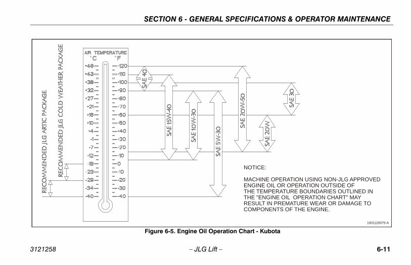
FICATIONS & OPERATOR MAINTENANCE
6-11
1001120075-A
OTICE:
ACHINE OPERATION USING NON-JLG APPROVEDNGINE OIL OR OPERATION OUTSIDE OFHE TEMPERATURE BOUNDARIES OUTLINED INHE "ENGINE OIL OPERATION CHART" MAYESULT IN PREMATURE WEAR OR DAMAGE TOOMPONENTS OF THE ENGINE.
art - Kubota
SECTION 6 - GENERAL SPECI
3121258 – JLG Lift –
N
METTRC
Figure 6-5. Engine Oil Operation Ch

SECTION 6 - GENERAL SPECIFICATIONS & OPERATOR MAINTENANCE
6-1 3121258
tion Diagram
2 – JLG Lift –
1
55 34
5
2 97
6,8 5
Figure 6-6. Operator Maintenance and Lubrica

FICATIONS & OPERATOR MAINTENANCE
6-13
N INTERVALS ARE BASED ON MACHINE OPERATIONMAL CONDITIONS. FOR MACHINES USED IN MULTI-SHIFT AND/OR EXPOSED TO HOSTILE ENVIRONMENTS OR CON-
BRICATION FREQUENCIES MUST BE INCREASED ACCORD-
ing Bearing
e Point(s) - Remote Fittingacity - A/Re - BGrval - Every 3 months or 150 hrs of operationments - Apply grease and rotate in 90 degree
tervals until bearing is completely lubricated
SECTION 6 - GENERAL SPECI
3121258 – JLG Lift –
6.3 OPERATOR MAINTENANCE
NOTE: The following numbers correspond to those in Figure 6-6., Operator Maintenance and Lubrication Diagram.
LUBRICATIOUNDER NOROPERATIONSDITIONS, LUINGLY.
1. Sw
LubCapLubInteCom
in
Table 6-9. Lubrication Specifications.
KEY SPECIFICATIONS
BG* Bearing Grease (JLG Part No. 3020029) Mobilith SHC 460.
HO Hydraulic Oil. API service classification GL-4, e.g. Mobilfluid 424.
EPGL Extreme Pressure Gear Lube (oil) meeting API Service Clas-sification GL-5 or Mil-Spec Mil-L-2105.
MPG Multipurpose Grease having a minimum dripping point of 350° F (177° C). Excellent water resistance and adhesive qualities, and being of extreme pressure type. (Timken OK 40 pounds minimum.)
EO Engine (crankcase) Oil. Gas - API SF, SH, SG class, MIL-L-2104. Diesel - API CC/CD class, MIL-L-2104B/MIL-L-2104C.
*MPG may be substituted for these lubricants, if necessary, but service intervals will be reduced.

SECTION 6 - GENERAL SPECIFICATIONS & OPERATOR MAINTENANCE
6-1 3121258
int(s) - Grease Fitting - A/Robile SHC 007 A/R
EASE BEARINGS. OVERGREASING BEARINGS WILLGE TO OUTER SEAL IN HOUSING.
4 – JLG Lift –
2. Swing Bearing/Worm Gear Teeth
Lube Point(s) - Grease FittingCapacity - A/RLube - BGInterval - A/R
Lube PoCapacityLube - MInterval -
DO NOT OVERGRRESULT IN DAMA
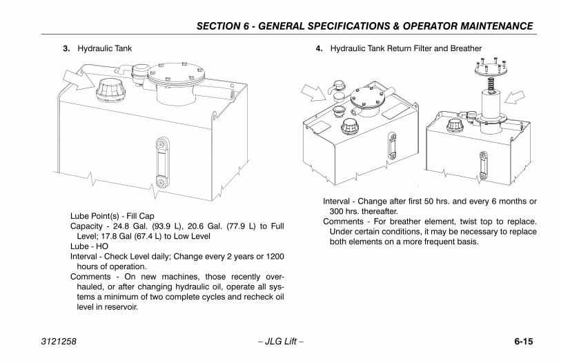
FICATIONS & OPERATOR MAINTENANCE
6-15
ydraulic Tank Return Filter and Breather
rval - Change after first 50 hrs. and every 6 months or0 hrs. thereafter.ments - For breather element, twist top to replace.der certain conditions, it may be necessary to replaceth elements on a more frequent basis.
SECTION 6 - GENERAL SPECI
3121258 – JLG Lift –
3. Hydraulic Tank
Lube Point(s) - Fill CapCapacity - 24.8 Gal. (93.9 L), 20.6 Gal. (77.9 L) to Full
Level; 17.8 Gal (67.4 L) to Low LevelLube - HOInterval - Check Level daily; Change every 2 years or 1200
hours of operation.Comments - On new machines, those recently over-
hauled, or after changing hydraulic oil, operate all sys-tems a minimum of two complete cycles and recheck oillevel in reservoir.
4. H
Inte30
ComUnbo

SECTION 6 - GENERAL SPECIFICATIONS & OPERATOR MAINTENANCE
6-1 3121258
ange with Filter - Kubota
int(s) - Fill Cap/Spin-on Element - 5.4 Quarts (5.1 L) w/FilterO Check level daily; change every 500 hours or six
hs, whichever comes first. Adjust final oil level byon dipstick.
6 – JLG Lift –
5. Wheel Drive Hub
Lube Point(s) - Level/Fill PlugCapacity - 25.5 oz. (0.75 L)(1/2 Full)Lube - EPGLInterval - Check level every 3 months or 150 hrs of opera-tion; change every 2 years or 1200 hours of operation
6. Oil Ch
Lube PoCapacityLube - EInterval -
montmark
OIL LEVEL CHECKAND FILL

FICATIONS & OPERATOR MAINTENANCE
6-17
il Change with Filter - GM
e Point(s) - Fill Cap/Spin-on Elementacity - 3.1 Quarts (3 L) w/Filtere - EOrval - Check level daily; change every 500 hours or sixonths, whichever comes first. Adjust final oil level byark on dipstick.
SECTION 6 - GENERAL SPECI
3121258 – JLG Lift –
7. Fuel Filter/Water Separator - Kubota
Lube Point(s) - Replaceable ElementInterval - Every year or 600 hours of operation
8. O
LubCapLubInte
mm

SECTION 6 - GENERAL SPECIFICATIONS & OPERATOR MAINTENANCE
6-1 3121258
& WHEELS
ment
nds a replacement tire be the same size, ply andnally installed on the machine. Please refer to theual for the part number of the approved tires for ahine model. If not using a JLG approved replace-ecommend that replacement tires have the follow-stics:
l or greater ply/load rating and size of original
tread contact width equal or greater than original
el diameter, width, and offset dimensions equal toriginal
oved for the application by the tire manufactureruding inflation pressure and maximum tire load)
ically approved by JLG Industries Inc. do not filled or ballast filled tire assembly with a pneu-en selecting and installing a replacement tire,
l tires are inflated to the pressure recommended to size variations between tire brands, both tiresxle should be the same.
8 – JLG Lift –
9. Charge Filter
Interval - Change after first 50 hrs. and every 6 months or300 hrs. thereafter.
Comments - Remove the engine tray retaining bolt andpull out engine tray to gain access.
6.4 TIRES
Tire Replace
JLG recommebrand as origiJLG Parts Manparticular macment tire, we ring characteri
• Equa
• Tire
• Whethe o
• Appr(incl
Unless specifreplace a foammatic tire. Whensure that alby JLG. Dueon the same a

FICATIONS & OPERATOR MAINTENANCE
6-19
stud holes in the wheels. The proper procedure for wheels is as follows:
art all nuts by hand to prevent cross threading. DOOT use a lubricant on threads or nuts.
ghten nuts in the following sequence.
e tightening of the nuts should be done in stages. Fol-wing the recommended sequence, tighten nuts per heel torque.
heel nuts should be torqued before first road use and ter each wheel removal. Check and torque every 3 onths or 150 hours of operation.
1
2
34
5
6
78
9
SECTION 6 - GENERAL SPECI
3121258 – JLG Lift –
Wheel and Tire Replacement
The rims installed on each product model have been designedfor stability requirements which consist of track width, tire pres-sure, and load capacity. Size changes such as rim width, centerpiece location, larger or smaller diameter, etc., without writtenfactory recommendations, may result in an unsafe conditionregarding stability.
Wheel InstallationIt is extremely important to apply and maintain proper wheelmounting torque.
WHEEL NUTS MUST BE INSTALLED AND MAINTAINED AT THE PROPERTORQUE TO PREVENT LOOSE WHEELS, BROKEN STUDS, AND POSSI-BLE DANGEROUS SEPARATION OF WHEEL FROM THE AXLE. BE SURETO USE ONLY THE NUTS MATCHED TO THE CONE ANGLE OF THEWHEEL.
Tighten the lug nuts to the proper torque to prevent wheels fromcoming loose. Use a torque wrench to tighten the fasteners. Ifyou do not have a torque wrench, tighten the fasteners with alug wrench, then immediately have a service garage or dealertighten the lug nuts to the proper torque. Over-tightening willresult in breaking the studs or permanently deforming the
mountingattaching
1. StN
2. Ti
3. Thlow
4. Wafm

SECTION 6 - GENERAL SPECIFICATIONS & OPERATOR MAINTENANCE
6-2 3121258
EMENTAL INFORMATIONng information is provided in accordance with thets of the European Machinery Directive 2006/42/nly applicable to CE machines.
powered machines, the equivalent continuous A-ound pressure level at the work platform is lessA)
ustion engine powered machines, guaranteeder Level (LWA) per European Directive 2000/14/
Emission in the Environment by Equipment forors) based on test methods in accordance withart B, Method 1 and 0 of the directive, is 104 dB.
ion total value to which the hand-arm system isdoes not exceed 2,5 m/s2. The highest root meanue of weighted acceleration to which the wholejected does not exceed 0,5 m/s2.
0 – JLG Lift –
6.5 SUPPLThe followirequiremenEC and is o
For electricWeighted sthan 70dB(
For combSound PowEC (NoiseUse OutdoAnnex III, P
The vibratsubjected square valbody is sub
Table 6-10. Wheel Torque Chart
TORQUE SEQUENCE
1st Stage 2nd Stage 3rd Stage
55 ft lbs (75 Nm) 135 ft lbs (180 Nm) 240 ft lbs (325 Nm)

TION 7 - INSPECTION AND REPAIR LOG
7-1
D REPAIR LOG
ir Log
nts
SEC
3121258 – JLG Lift –
SECTION 7. INSPECTION ANMachine Serial Number _______________________________________
Table 7-1. Inspection and Repa
Date Comme

SECTION 7 - INSPECTION AND REPAIR LOG
7-2 3121258
og
– JLG Lift –
Table 7-1. Inspection and Repair L
Date Comments

TRA
NS
FE
R O
F O
WN
ER
SH
IP
To P
rod
uct
Ow
ner
:If
yo
u n
ow
ow
n b
ut
AR
E N
OT
th
e o
rig
inal
pu
rch
aser
of
the
pro
du
ct c
over
ed b
y th
is
man
ual
, we
wo
uld
like
to
kn
ow
wh
o y
ou
are
. Fo
r th
e p
urp
ose
of
rece
ivin
g s
afet
y-re
late
d
bulle
tin
s, it
is v
ery
imp
ort
ant
to k
eep
JL
G In
du
stri
es, I
nc.
up
dat
ed w
ith
th
e cu
rren
t ow
ner
ship
of
all J
LG
pro
du
cts.
JL
G m
ain
tain
s ow
ner
info
rmat
ion
for
each
JL
G p
rod
uct
an
d u
ses
this
info
rmat
ion
in c
ases
wh
ere
ow
ner
no
tifi
cati
on
is n
eces
sary
.P
leas
e u
se t
his
form
to
pro
vid
e JL
G w
ith
up
dat
ed in
form
atio
n w
ith
reg
ard
to
th
e cu
rren
t ow
ner
ship
of
JLG
pro
du
cts.
Ple
ase
retu
rn c
om
ple
ted
form
to
th
e JL
G P
rod
uct
S
afet
y &
Rel
iab
ility
Dep
artm
ent
via
facs
imile
or
mai
l to
ad
dre
ss a
s sp
ecif
ied
bel
ow
.
Th
ank
You
,P
rod
uct
Saf
ety
& R
elia
bili
ty D
epar
tmen
tJL
G In
du
stri
es, I
nc.
1322
4 F
ou
nta
inh
ead
Pla
zaH
ager
stow
n, M
D21
742
US
ATe
lep
ho
ne:
+1-
717-
485-
6591
Fax:
+1-
301-
745-
3713
NO
TE
: L
ease
d o
r re
nte
d u
nit
s sh
ou
ld n
ot
be
incl
ud
ed o
n t
his
form
.
Mfg
. Mo
del
: __
____
____
___ _
____
____
____
____
____
____
____
____
____
____
____
____
_
Ser
ial N
um
ber
: __
____
____
____
____
____
____
____
____
____
____
____
____
____
____
__
Pre
vio
us
Ow
ner
: __
____
____
____
____
____
____
____
____
____
____
____
____
____
____
_
Ad
dre
ss:
____
____
____
____
____
____
____
____
____
____
____
____
____
____
____
____
_
____
____
____
____
____
____
____
____
____
____
____
____
____
____
____
____
____
____
_
Co
un
try:
__
____
____
____
____
____
___
Tele
ph
on
e: (
____
___)
___
____
____
____
____
_
Dat
e o
f Tr
ansf
er:
____
____
____
____
____
____
____
____
_
Cu
rren
t O
wn
er:
____
____
____
____
____
____
____
____
____
____
____
____
____
____
____
Ad
dre
ss:
____
____
____
____
____
____
____
____
____
____
____
____
____
____
____
____
_
____
____
____
____
____
____
____
____
____
____
____
____
____
____
____
____
____
____
_
Co
un
try:
__
____
____
____
____
____
___
Tele
ph
on
e: (
____
___)
___
____
____
____
____
_
Wh
o in
yo
ur
org
aniz
atio
n s
ho
uld
we
no
tify
?
Nam
e:
____
____
____
____
____
____
____
____
____
____
____
____
____
____
____
____
___
Tit
le:_
____
____
____
____
____
____
____
____
____
____
____
____
____
____
____
____
___
��
����
���
�
��
� ��
�
�
��
��


Corporate Office
JLG Industries, Inc.
1 JLG Drive
McConnellsburg PA. 17233-9533
USA
(717) 485-5161
(717) 485-6417
JLG Worldwide LocationsJLG Industries (Australia)P.O. Box 511911 Bolwarra RoadPort MacquarieN.S.W. 2444Australia
+61 2 65 811111
+61 2 65813058
JLG Latino Americana Ltda.Rua Eng. Carlos Stevenson,80-Suite 7113092-310 Campinas-SPBrazil
+55 19 3295 0407
+55 19 3295 1025
JLG Industries (UK) LtdBentley HouseBentley AvenueMiddletonGreater ManchesterM24 2GP - England
+44 (0)161 654 1000
+44 (0)161 654 1001
JLG France SASZ.I. de Baulieu47400 FauilletFrance
+33 (0)5 53 88 31 70
+33 (0)5 53 88 31 79
JLG Deutschland GmbHMax-Planck-Str. 21D - 27721 Ritterhude - IhlpohlGermany
+49 (0)421 69 350 20
+49 (0)421 69 350 45
JLG Equipment Services Ltd.Rm 1107 Landmark North39 Lung Sum AvenueSheung Shui N. T.Hong Kong
(852) 2639 5783
(852) 2639 5797
JLG Industries (Italia) s.r.l.Via Po. 2220010 Pregnana Milanese - MIItaly
+39 029 359 5210
+39 029 359 5845
Oshkosh-JLG Singapore Technology Equipment Pte Ltd29 Tuas Ave 4,Jurong Industrial EstateSingapore, 639379
+65-6591 9030
+65-6591 9031
Plataformas Elevadoras JLG Iberica, S.L.Trapadella, 2P.I. Castellbisbal Sur08755 Castellbisbal, BarcelonaSpain
+34 93 772 4700
+34 93 771 1762
JLG Sverige ABEnkopingsvagen 150Box 704SE - 176 27 JarfallaSweden
+46 (0)850 659 500
+46 (0)850 659 534
www.jlg.com
3121258