operation and safety manual - csapps.jlg.com scissor lifts...revision log original issue ......
TRANSCRIPT
d Safety Manualons, Keep this manual with the machine at all times.
ANSI
Models1930ES/2032ES/2632ES/
OperatioOri
®
2646ES/3246ES Built - S/N-0200239382 to Present
n anginal Instructi
USA
China Built - S/N-B200020297 to PresentMexico Built - S/N-M200000100 to PresentBelgium Built - S/N-1200025021 to PresentP/N - 3121655December 18, 2017

FOREWORD
a
TRICAL/ELECTRONIC COMPONENTS. SHOULDING ELECTRICAL/ELECTRONIC COMPONENTS,
E OF 750 PSI (52 BAR) AT A MINIMUM DIS-NENTS. IF ELECTRICAL/ELECTRONIC COMPO-E FOR BRIEF TIME PERIODS TO AVOID HEAVY
all times.
, lessors, and lessees with the precautions andperation for its intended purpose.
erves the right to make specification changes information.
3121655 – JLG Lift –
FOREWORD
IT IS A GOOD PRACTICE TO AVOID PRESSURE-WASHING ELECPRESSURE-WASHING BE UTILIZED TO WASH AREAS CONTAINJLG INDUSTRIES, INC. RECOMMENDS A MAXIMUM PRESSURTANCE OF 12 INCHES (30.5 CM) AWAY FROM THESE COMPONENTS ARE SPRAYED, SPRAYING MUST NOT BE DIRECT AND BSATURATION.
This manual is a very important tool! Keep it with the machine at
The purpose of this manual is to provide owners, users, operatorsoperating procedures essential for the safe and proper machine o
Due to continuous product improvements, JLG Industries, Inc. reswithout prior notification. Contact JLG Industries, Inc. for updated
FOREWORD
b 3121655
SIGNAL WORDS
INDAVOWIL
INDAVOWIL
OTENTIALIT Y HA Z ARDOUS SITUATION. IF NOTRESULT IN MINOR OR MODERATE INJURY. IT MAYINST UNSAFE PRACTICES. THIS DECAL WILL HAVE AOUND.
RMATION OR A COMPANY POLICY THAT RELATESDIRECTLY TO THE SAFETY OF PERSONNEL OR PRO-PERTY.
the potential personalsymbol to avoid possi-
– JLG Lift –
SAFETY ALERT SYMBOLS AND SAFETY
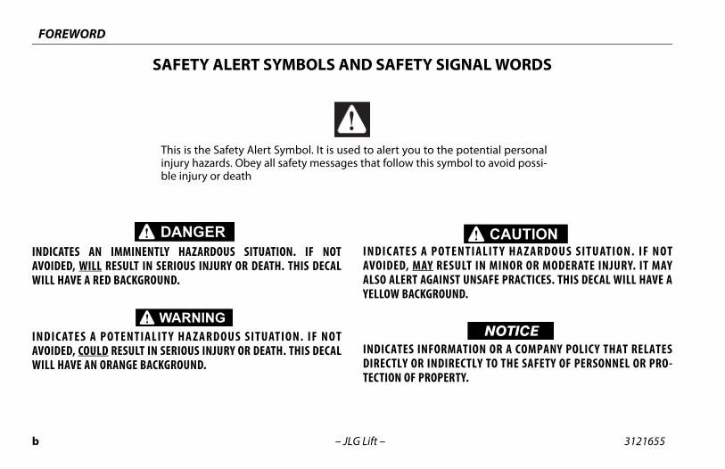
ICATES AN IMMINENTLY HAZARDOUS SITUATION. IF NOTIDED, WILL RESULT IN SERIOUS INJURY OR DEATH. THIS DECALL HAVE A RED BACKGROUND.
IC ATES A POTENTIALIT Y HA Z ARDOUS SITUATION. IF NOTIDED, COULD RESULT IN SERIOUS INJURY OR DEATH. THIS DECALL HAVE AN ORANGE BACKGROUND.
INDIC ATES A PAVOIDED, MAY ALSO ALERT AGAYELLOW BACKGR
INDICATES INFODIRECTLY OR INTECTION OF PRO
This is the Safety Alert Symbol. It is used to alert you to injury hazards. Obey all safety messages that follow this ble injury or death

FOREWORD
c
ct:
duct Safety and Reliability Department Industries, Inc.24 Fountainhead Plazaerstown, MD 21742
our Local JLG Office addresses on manual rear cover)
A:
Free: 877-JLG-SAFE (877-554-7233)
de USA:
ne: 240-420-2661ail: [email protected]
ent Reporting
ct Safety Publi-ns
nt Owner tes
tions Regarding ct Safety
• Standards and Regula-tions Compliance Infor-mation
• Questions Regarding Spe-cial Product Applications
• Questions Regarding Product Modifications
3121655 – JLG Lift –
THIS PRODUCT MUST COMPLY WITH ALL SAFETY RELATED BULLE-TINS. CONTACT JLG INDUSTRIES, INC. OR THE LOCAL AUTHORIZEDJLG REPRESENTATIVE FOR INFORMATION REGARDING SAFET Y-RELATED BULLETINS WHICH MAY HAVE BEEN ISSUED FOR THISPRODUCT.
JLG INDUSTRIES, INC. SENDS SAFETY RELATED BULLETINS TO THEOWNER OF RECORD OF THIS MACHINE. CONTACT JLG INDUSTRIES,INC. TO ENSURE THAT THE CURRENT OWNER RECORDS ARE UPDATEDAND ACCURATE.
JLG INDUSTRIES, INC. MUST BE NOTIFIED IMMEDIATELY IN ALLINSTANCES WHERE JLG PRODUCTS HAVE BEEN INVOLVED IN AN ACCI-DENT INVOLVING BODILY INJURY OR DEATH OF PERSONNEL ORWHEN SUBSTANTIAL DAMAGE HAS OCCURRED TO PERSONAL PROP-ERTY OR THE JLG PRODUCT.
Conta
ProJLG132Hag
or Y(See
In US
Toll
Outsi
PhoE-m
For:• Accid
• Producatio
• CurreUpda
• QuesProdu

FOREWORD
d 3121655
OrigManManManManManMan
– JLG Lift –
REVISION LOGinal Issue. . . . . . . . . . . . . . . . . . . December 1, 2014ual Revised . . . . . . . . . . . . . . . . July 22, 2015ual Revised . . . . . . . . . . . . . . . . March 7, 2016ual Revised . . . . . . . . . . . . . . . . October 10, 2016ual Revised . . . . . . . . . . . . . . . . June 19, 2017ual Revised . . . . . . . . . . . . . . . . October 13, 2017ual Revised . . . . . . . . . . . . . . . . December 18, 2017

TABLE OF CONTENTS
3121 i
SECT PARAGRAPH, SUBJECT PAGE
SECT
SECTTION
PREPARATION, INSPECTION, AND MAINTENANCE . . . . . . . . . . . . . . . . . . . . . . . . . . . . . . . . .2-2
Pre-Start Inspection. . . . . . . . . . . . . . . . . . . . . . . . . . 2-3Function Check . . . . . . . . . . . . . . . . . . . . . . . . . . . . . . 2-4General . . . . . . . . . . . . . . . . . . . . . . . . . . . . . . . . . . . . . 2-7
3 - MACHINE CONTROLS, INDICATORS AND OP-
GENERAL . . . . . . . . . . . . . . . . . . . . . . . . . . . . . . . . . . . . . . .3-1DESCRIPTION . . . . . . . . . . . . . . . . . . . . . . . . . . . . . . . . . . .3-1OPERATING CHARACTERISTICS AND LIMITATIONS . . . . . . . . . . . . . . . . . . . . . . . . . . . . . . . . . . .3-2
General . . . . . . . . . . . . . . . . . . . . . . . . . . . . . . . . . . . . . 3-2Placards . . . . . . . . . . . . . . . . . . . . . . . . . . . . . . . . . . . . . 3-2Capacities . . . . . . . . . . . . . . . . . . . . . . . . . . . . . . . . . . . 3-2Stability . . . . . . . . . . . . . . . . . . . . . . . . . . . . . . . . . . . . . 3-2
PLATFORM LOADING . . . . . . . . . . . . . . . . . . . . . . . . . . .3-2BATTERY CHARGING . . . . . . . . . . . . . . . . . . . . . . . . . . . .3-4
Operation . . . . . . . . . . . . . . . . . . . . . . . . . . . . . . . . . . . 3-4Battery Charger Fault Codes . . . . . . . . . . . . . . . . . 3-5
MDI (MULTIFUNCTION DIGITAL INDICATOR) . . . . .3-6MDI Description . . . . . . . . . . . . . . . . . . . . . . . . . . . . . 3-7
GROUND CONTROL STATION. . . . . . . . . . . . . . . . . . . .3-8Controls and Indicators . . . . . . . . . . . . . . . . . . . . . . 3-8Manual Descent Control . . . . . . . . . . . . . . . . . . . . . 3-9
655 – JLG Lift –
ION - PARAGRAPH, SUBJECT PAGE SECTION -
ION - 1 - SAFETY PRECAUTIONS1.1 GENERAL. . . . . . . . . . . . . . . . . . . . . . . . . . . . . . . . . . . . . . . 1-11.2 PRE-OPERATION. . . . . . . . . . . . . . . . . . . . . . . . . . . . . . . . 1-2
Operator Training and Knowledge . . . . . . . . . . . 1-2Workplace Inspection . . . . . . . . . . . . . . . . . . . . . . . 1-2Machine Inspection . . . . . . . . . . . . . . . . . . . . . . . . . 1-3
1.3 OPERATION . . . . . . . . . . . . . . . . . . . . . . . . . . . . . . . . . . . . 1-3General . . . . . . . . . . . . . . . . . . . . . . . . . . . . . . . . . . . . . 1-3Trip and Fall Hazards . . . . . . . . . . . . . . . . . . . . . . . . 1-5Electrocution Hazards . . . . . . . . . . . . . . . . . . . . . . . 1-6Tipping Hazards. . . . . . . . . . . . . . . . . . . . . . . . . . . . . 1-7Crushing and Collision Hazards . . . . . . . . . . . . . . 1-9
1.4 TOWING, LIFTING, AND HAULING . . . . . . . . . . . . . .1-111.5 MAINTENANCE . . . . . . . . . . . . . . . . . . . . . . . . . . . . . . . .1-11
Maintenance Hazards . . . . . . . . . . . . . . . . . . . . . . 1-11Battery Hazards . . . . . . . . . . . . . . . . . . . . . . . . . . . . 1-12
ION - 2 - USER RESPONSIBILITIES, MACHINE PREPARA- & INSPECTION2.1 PERSONNEL TRAINING . . . . . . . . . . . . . . . . . . . . . . . . . . 2-1
Operator Training . . . . . . . . . . . . . . . . . . . . . . . . . . . 2-1Training Supervision . . . . . . . . . . . . . . . . . . . . . . . . 2-1Operator Responsibility . . . . . . . . . . . . . . . . . . . . . 2-1
2.2
SECTION -ERATION
3.13.23.3
3.43.5
3.6
3.7
TABLE OF CONTENTS
ii 3121655
SECTION AGRAPH, SUBJECT PAGE
3.83.9
3.10
3.113.123.133.143.153.16
SECTION4.1
RGENCY OPERATION . . . . . . . . . . . . . . . . . . . . . . . 4-2perator Unable to Control Machine . . . . . . . . . 4-2atform Caught Overhead . . . . . . . . . . . . . . . . . . . 4-3ghting of Tipped Machine . . . . . . . . . . . . . . . . . . 4-3st-Incident Inspection . . . . . . . . . . . . . . . . . . . . . 4-3
DENT NOTIFICATION . . . . . . . . . . . . . . . . . . . . . . . 4-3
ENERAL SPECIFICATIONS AND OPERATOR EODUCTION . . . . . . . . . . . . . . . . . . . . . . . . . . . . . . . . 5-1
RATING SPECIFICATIONS . . . . . . . . . . . . . . . . . . . 5-2imensional Data . . . . . . . . . . . . . . . . . . . . . . . . . . . . 5-6otors . . . . . . . . . . . . . . . . . . . . . . . . . . . . . . . . . . . . . . 5-7tteries . . . . . . . . . . . . . . . . . . . . . . . . . . . . . . . . . . . . . 5-7ttery Charger . . . . . . . . . . . . . . . . . . . . . . . . . . . . . . 5-7ttery Charger/AC Inverter . . . . . . . . . . . . . . . . . . 5-8pacities . . . . . . . . . . . . . . . . . . . . . . . . . . . . . . . . . . . 5-9
res . . . . . . . . . . . . . . . . . . . . . . . . . . . . . . . . . . . . . . . . 5-9itical Stability Weights . . . . . . . . . . . . . . . . . . . 5-10brication . . . . . . . . . . . . . . . . . . . . . . . . . . . . . . . . 5-11
RATOR MAINTENANCE . . . . . . . . . . . . . . . . . . . . 5-12issor Arms - Safety Prop . . . . . . . . . . . . . . . . . . 5-13
il Check Procedure (1) . . . . . . . . . . . . . . . . . . . . 5-13wer (2) & Upper Slide Pads (3) . . . . . . . . . . . . 5-15
– JLG Lift –
- PARAGRAPH, SUBJECT PAGE SECTION - PAR
PLATFORM CONTROL STATION . . . . . . . . . . . . . . . 3-10PLATFORM OPERATION . . . . . . . . . . . . . . . . . . . . . . . 3-14
Raising . . . . . . . . . . . . . . . . . . . . . . . . . . . . . . . . . . . . . 3-14Lowering. . . . . . . . . . . . . . . . . . . . . . . . . . . . . . . . . . . 3-14Arm Guards (If equipped) . . . . . . . . . . . . . . . . . . . 3-15Steering . . . . . . . . . . . . . . . . . . . . . . . . . . . . . . . . . . . . 3-15Driving . . . . . . . . . . . . . . . . . . . . . . . . . . . . . . . . . . . . . 3-15Driving Forward . . . . . . . . . . . . . . . . . . . . . . . . . . . . 3-15Driving in Reverse . . . . . . . . . . . . . . . . . . . . . . . . . . 3-15
SOFT-TOUCH SYSTEM - (OPTION). . . . . . . . . . . . . . 3-17Operation . . . . . . . . . . . . . . . . . . . . . . . . . . . . . . . . . . 3-17
PLATFORM DECK EXTENSION . . . . . . . . . . . . . . . . . 3-18PLATFORM RAILS - FOLD-DOWN PROCEDURE . 3-19PARKING AND STOWING . . . . . . . . . . . . . . . . . . . . . . 3-21TIE DOWN/LIFT LUGS . . . . . . . . . . . . . . . . . . . . . . . . . 3-22LIFTING. . . . . . . . . . . . . . . . . . . . . . . . . . . . . . . . . . . . . . . 3-22TOWING . . . . . . . . . . . . . . . . . . . . . . . . . . . . . . . . . . . . . . 3-25
Remote Electric Brake Release. . . . . . . . . . . . . . . 3-25Push Button Electric Brake Release . . . . . . . . . . 3-25Mechanical Brake Release . . . . . . . . . . . . . . . . . . . 3-26
- 4 - EMERGENCY PROCEDURESGENERAL . . . . . . . . . . . . . . . . . . . . . . . . . . . . . . . . . . . . . . .4-1
Emergency Stop Switch. . . . . . . . . . . . . . . . . . . . . . 4-1Manual Descent . . . . . . . . . . . . . . . . . . . . . . . . . . . . . 4-1
4.2 EMEOPlRiPo
4.3 INCI
SECTION - 5 - GMAINTENANC
5.1 INTR5.2 OPE
DMBaBaBaCaTiCrLu
5.3 OPEScOLo

TABLE OF CONTENTS
3121 iii
SECT PARAGRAPH, SUBJECT PAGE
6 - INSPECTION AND REPAIR LOG
7 - ACCESSORIES1/2 AIRLINE . . . . . . . . . . . . . . . . . . . . . . . . . . . . . . . . . . . . .7-4ANTI-VANDALISM PACKAGE. . . . . . . . . . . . . . . . . . . . .7-4ELECTRICIAN’S TREE . . . . . . . . . . . . . . . . . . . . . . . . . . . .7-4
Safety Precautions . . . . . . . . . . . . . . . . . . . . . . . . . . . 7-5Preparation and Inspection . . . . . . . . . . . . . . . . . . 7-5Operation . . . . . . . . . . . . . . . . . . . . . . . . . . . . . . . . . . . 7-5
ELECTRICIAN’S PACKAGE. . . . . . . . . . . . . . . . . . . . . . . .7-6Safety Precautions . . . . . . . . . . . . . . . . . . . . . . . . . . . 7-6Preparation and Inspection . . . . . . . . . . . . . . . . . . 7-6Operation . . . . . . . . . . . . . . . . . . . . . . . . . . . . . . . . . . . 7-6
PANEL CARRIER . . . . . . . . . . . . . . . . . . . . . . . . . . . . . . . . .7-7Safety Precautions . . . . . . . . . . . . . . . . . . . . . . . . . . . 7-8Preparation and Inspection . . . . . . . . . . . . . . . . . . 7-8Operation . . . . . . . . . . . . . . . . . . . . . . . . . . . . . . . . . . . 7-8
PIPE RACKS . . . . . . . . . . . . . . . . . . . . . . . . . . . . . . . . . . . . .7-9Safety Precautions . . . . . . . . . . . . . . . . . . . . . . . . . . 7-10Preparation and Inspection . . . . . . . . . . . . . . . . . 7-10Operation . . . . . . . . . . . . . . . . . . . . . . . . . . . . . . . . . . 7-10
PLANT PACKAGE. . . . . . . . . . . . . . . . . . . . . . . . . . . . . . 7-11Safety Precautions . . . . . . . . . . . . . . . . . . . . . . . . . . 7-11Preparation and Inspection . . . . . . . . . . . . . . . . . 7-11Operation . . . . . . . . . . . . . . . . . . . . . . . . . . . . . . . . . . 7-11
655 – JLG Lift –
ION - PARAGRAPH, SUBJECT PAGE SECTION -
5.4 TIRES AND WHEELS . . . . . . . . . . . . . . . . . . . . . . . . . . . .5-17Tire Wear and Damage . . . . . . . . . . . . . . . . . . . . . 5-17Wheel and Tire Replacement . . . . . . . . . . . . . . . 5-17Wheel Installation . . . . . . . . . . . . . . . . . . . . . . . . . . 5-17
5.5 SUPPLEMENTAL INFORMATION . . . . . . . . . . . . . . . .5-185.6 DECAL INSTALLATIONS . . . . . . . . . . . . . . . . . . . . . . . .5-195.7 DIAGNOSTIC TROUBLE CODES (DTC) . . . . . . . . . . .5-29
Introduction . . . . . . . . . . . . . . . . . . . . . . . . . . . . . . . 5-295.8 DIAGNOSTIC TROUBLE CODES (DTC) CHECK
TABLES. . . . . . . . . . . . . . . . . . . . . . . . . . . . . . . . . . . . . . . .5-300-0 Help Comments . . . . . . . . . . . . . . . . . . . . . . . . 5-302-1 Power-Up . . . . . . . . . . . . . . . . . . . . . . . . . . . . . . 5-322-2 Platform Controls. . . . . . . . . . . . . . . . . . . . . . . 5-332-3 Ground Controls. . . . . . . . . . . . . . . . . . . . . . . . 5-342-5 Function Prevented. . . . . . . . . . . . . . . . . . . . . 5-353-1 Line Contactor Open Circuit. . . . . . . . . . . . . 5-373-2 Line Contactor Short Circuit. . . . . . . . . . . . . 5-373-3 Ground Output Driver . . . . . . . . . . . . . . . . . . 5-374-2 Thermal Limit (SOA) . . . . . . . . . . . . . . . . . . . . 5-404-4 Battery Supply. . . . . . . . . . . . . . . . . . . . . . . . . . 5-416-6 Communication . . . . . . . . . . . . . . . . . . . . . . . . 5-416-7 Accessory . . . . . . . . . . . . . . . . . . . . . . . . . . . . . . 5-427-7 Electric Motor . . . . . . . . . . . . . . . . . . . . . . . . . . 5-438-1 Tilt Sensor . . . . . . . . . . . . . . . . . . . . . . . . . . . . . . 5-448-2 Platform Load Sense . . . . . . . . . . . . . . . . . . . . 5-459-9 Hardware . . . . . . . . . . . . . . . . . . . . . . . . . . . . . . 5-46
SECTION -
SECTION -7.17.27.3
7.4
7.5
7.6
7.7
TABLE OF CONTENTS
iv 3121655
SECTION AGRAPH, SUBJECT PAGE
7.87.97.107.11
7.12
7.13
7.14
7.15
– JLG Lift –
- PARAGRAPH, SUBJECT PAGE SECTION - PAR
PLATFORM BOX COVER . . . . . . . . . . . . . . . . . . . . . . . 7-12PLATFORM BOX HANGER . . . . . . . . . . . . . . . . . . . . . 7-12PLATFORM RAIL PADDING . . . . . . . . . . . . . . . . . . . . 7-13PLATFORM WORKLIGHTS . . . . . . . . . . . . . . . . . . . . . 7-14
Operation . . . . . . . . . . . . . . . . . . . . . . . . . . . . . . . . . . 7-14PLUMBER’S PACKAGE . . . . . . . . . . . . . . . . . . . . . . . . . 7-15
Safety Precautions . . . . . . . . . . . . . . . . . . . . . . . . . . 7-15Preparation and Inspection . . . . . . . . . . . . . . . . . 7-15Operation . . . . . . . . . . . . . . . . . . . . . . . . . . . . . . . . . . 7-15
QUIKWELDER™ . . . . . . . . . . . . . . . . . . . . . . . . . . . . . . . 7-16Safety Precautions . . . . . . . . . . . . . . . . . . . . . . . . . . 7-17Preparation and Inspection . . . . . . . . . . . . . . . . . 7-17Operation . . . . . . . . . . . . . . . . . . . . . . . . . . . . . . . . . . 7-18
VISE . . . . . . . . . . . . . . . . . . . . . . . . . . . . . . . . . . . . . . . . . . 7-18Safety Precautions . . . . . . . . . . . . . . . . . . . . . . . . . . 7-19Preparation and Inspection . . . . . . . . . . . . . . . . . 7-19Operation . . . . . . . . . . . . . . . . . . . . . . . . . . . . . . . . . . 7-19
WORKSTATION . . . . . . . . . . . . . . . . . . . . . . . . . . . . . . . 7-19Safety Precautions . . . . . . . . . . . . . . . . . . . . . . . . . . 7-20Preparation and Inspection . . . . . . . . . . . . . . . . . 7-20Operation . . . . . . . . . . . . . . . . . . . . . . . . . . . . . . . . . . 7-20

TABLE OF CONTENTS
3121 v
SECT PARAGRAPH, SUBJECT PAGE
Decal Location - 2646ES & 3246ES - Sheet 2. . . . 5-24
LIST OF TABLES
Minimum Approach Distances (M.A.D.) . . . . . . . . . 1-7Beaufort Scale (For Reference Only) . . . . . . . . . . . . 1-8Inspection and Maintenance Table . . . . . . . . . . . . . 2-2Tilt Activation vs. Height . . . . . . . . . . . . . . . . . . . . . . . 2-5High Drive Speed Cutout Height . . . . . . . . . . . . . . . 2-5Battery Charger Flash Codes . . . . . . . . . . . . . . . . . . . 3-5Operating Specifications . . . . . . . . . . . . . . . . . . . . . . . 5-2Platform Capacities . . . . . . . . . . . . . . . . . . . . . . . . . . . . 5-5Dimensions. . . . . . . . . . . . . . . . . . . . . . . . . . . . . . . . . . . . 5-6Battery Specifications . . . . . . . . . . . . . . . . . . . . . . . . . . 5-7Battery Charger Specifications. . . . . . . . . . . . . . . . . . 5-7Battery Charger/AC Inverter Specifications. . . . . . 5-8Fluid Capacities . . . . . . . . . . . . . . . . . . . . . . . . . . . . . . . . 5-9Tire Specifications . . . . . . . . . . . . . . . . . . . . . . . . . . . . . 5-9Critical Stability Weights . . . . . . . . . . . . . . . . . . . . . . 5-10Hydraulic Oil Specifications . . . . . . . . . . . . . . . . . . . 5-11Wheel Torque Chart. . . . . . . . . . . . . . . . . . . . . . . . . . . 5-18Decal Location Legend. . . . . . . . . . . . . . . . . . . . . . . . 5-25Inspection and Repair Log. . . . . . . . . . . . . . . . . . . . . . 6-1Accessories (All Models) . . . . . . . . . . . . . . . . . . . . . . . . 7-1Options/Accessories Relationship Table (All Models). . . . . . . . . . . . . . . . . . . . . . . . . . . . . . . . . . . 7-2
655 – JLG Lift –
ION - PARAGRAPH, SUBJECT PAGE SECTION -
LIST OF FIGURES
2-1. Daily Walk-Around Inspection - Sheet 1 . . . . . . . . . 2-62-2. Daily Walk-Around Inspection - Sheet 2 . . . . . . . . . 2-72-3. Switch Locations . . . . . . . . . . . . . . . . . . . . . . . . . . . . . . . 2-83-1. Location of Machine Controls. (All Models) . . . . . . 3-33-2. Multifunction Digital Indicator . . . . . . . . . . . . . . . . . . 3-63-3. Ground Control Station Panel. . . . . . . . . . . . . . . . . . . 3-83-4. Platform Control Station . . . . . . . . . . . . . . . . . . . . . . .3-103-5. Grade and Sideslope - Driving - Platform
Stowed . . . . . . . . . . . . . . . . . . . . . . . . . . . . . . . . . . . . . .3-163-6. Soft-Touch System . . . . . . . . . . . . . . . . . . . . . . . . . . . .3-173-7. Platform Deck Extension. (All Models) . . . . . . . . . .3-183-8. Platform Rails - Fold Down Sequence . . . . . . . . . .3-203-9. Securing Control Station to Platform . . . . . . . . . . .3-213-10. Lifting and Tie Down Diagram . . . . . . . . . . . . . . . . .3-233-11. Lifting and Tie Down Chart . . . . . . . . . . . . . . . . . . . .3-243-12. Manual Disengage . . . . . . . . . . . . . . . . . . . . . . . . . . . .3-265-1. Lubrication Diagram . . . . . . . . . . . . . . . . . . . . . . . . . .5-125-2. Lower Slide Pad Channel . . . . . . . . . . . . . . . . . . . . . .5-155-3. Upper Slide Pad Channel . . . . . . . . . . . . . . . . . . . . . .5-165-4. Decal Location - 1930ES- Sheet 1. . . . . . . . . . . . . . .5-195-5. Decal Location - 1930ES - Sheet 2 . . . . . . . . . . . . . .5-205-6. Decal Location - 2032ES & 2632ES - Sheet 1 . . . .5-215-7. Decal Location - 2032ES & 2632ES - Sheet 2 . . . .5-225-8. Decal Location - 2646ES & 3246ES - Sheet 1 . . . .5-23
5-9.
1-11-22-12-22-33-15-15-25-35-45-55-65-75-85-95-105-115-126-17-17-2

TABLE OF CONTENTS
vi 3121655
SECTION AGRAPH, SUBJECT PAGE
nally
– JLG Lift –
- PARAGRAPH, SUBJECT PAGE SECTION - PAR
This page left blank intentio

SECTION 1 - SAFETY PRECAUTIONS
1-1
AUTIONS
sections contain the responsibilities of the owner,operator, lessor, and lessee concerning safety, train-spection, maintenance, application, and operation.Ifare any questions with regard to safety, training,
ction, maintenance, application, and operation, contact JLG Industries, Inc. (“JLG”).
OMPLY WITH THE SAFETY PRECAUTIONS LISTED IN THIS MAN-ESULT IN MACHINE DAMAGE, PROPERTY DAMAGE, PERSONAL
EATH.
3121655 – JLG Lift –
SECTION 1. SAFETY PREC
1.1 GENERALThis section outlines the necessary precautions for properand safe machine usage and maintenance. In order to pro-mote proper machine usage, it is mandatory that a dailyroutine is established based on the content of this manual.A maintenance program, using the information providedin this manual and the Service and Maintenance Manual,must also be established by a qualified person and mustbe followed to ensure that the machine is safe to operate.
The owner/user/operator/lessor/lessee of the machinemust not accept operating responsibility until this manualhas been read, training is accomplished, and operation ofthe machine has been completed under the supervision ofan experienced and qualified operator.
Theseuser, ing, inthere inspeplease
FAILURE TO CUAL COULD RINJURY OR D

SECTION 1 - SAFETY PRECAUTIONS
1-2 3121655
1.2
Ope•
•
•
•
the machine is to be used in a manner which iscope of its intended application as determined
g personnel must be familiar with the emer-ols and emergency operation of the machine asthis manual.
rstand, and obey all applicable employer, local,mental regulations as they pertain to your utili-pplication of the machine.
ection to avoid all hazards in the work area must bee user before and during operation of the
rate or raise the platform from a position oners, railway cars, floating vessels, scaffolds orment unless the application is approved in writ-
ration, check work area for overhead hazardsctric lines, bridge cranes, and other potential
structions.
surfaces for holes, bumps, drop-offs, obstruc-, concealed holes, and other potential hazards.
– JLG Lift –
PRE-OPERATION
rator Training and KnowledgeThe Operation and Safety Manual must be read and under-stood in its entirety before operating the machine. For clari-fication, questions, or additional information regarding anyportions of this manual, contact JLG Industries, Inc.
An operator must not accept operating responsibilitiesuntil adequate training has been given by competent andauthorized persons.
Allow only those authorized and qualified personnel tooperate the machine who have demonstrated that theyunderstand the safe and proper operation and mainte-nance of the unit.
Read, understand, and obey all DANGERS, WARNINGS, CAU-TIONS, and operating instructions on the machine and inthis manual.
• Ensure thatwithin the sby JLG.
• All operatingency contrspecified in
• Read, undeand governzation and a
Workplace Insp• Precautions
taken by thmachine.
• Do not opetrucks, trailother equiping by JLG.
• Before opesuch as eleoverhead ob
• Check floortions, debris
SECTION 1 - SAFETY PRECAUTIONS
1-3
operate any machine on which the safety or instruc-acards or decals are missing or illegible.
the machine for modifications to original compo- Ensure that any modifications have been approved.
accumulation of debris on platform deck. Keep mud,ase, and other slippery substances from footwear
atform deck.
RATION
e operation requires your full attention. Bring thene to a full stop before using any device, i.e. cells, two-way radios, etc. that will distract your attentionafely operating the machine.
t use the machine for any purpose other than posi- personnel, their tools, and equipment.
operation, the user must be familiar with thene capabilities and operating characteristics of allns.
operate a malfunctioning machine. If a malfunction, shut down the machine. Remove the unit from ser-d notify the proper authorities.
3121655 – JLG Lift –
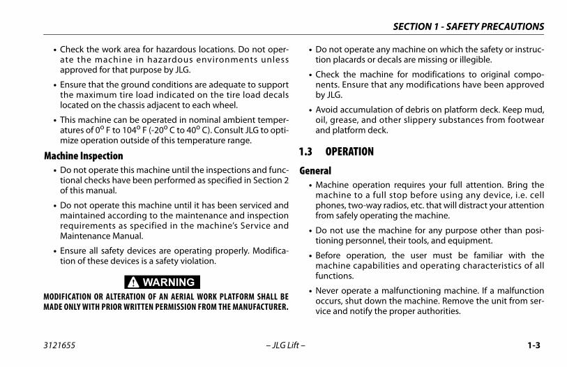
• Check the work area for hazardous locations. Do not oper-ate the machine in hazardous environments unlessapproved for that purpose by JLG.
• Ensure that the ground conditions are adequate to supportthe maximum tire load indicated on the tire load decalslocated on the chassis adjacent to each wheel.
• This machine can be operated in nominal ambient temper-atures of 0o F to 104o F (-20o C to 40o C). Consult JLG to opti-mize operation outside of this temperature range.
Machine Inspection• Do not operate this machine until the inspections and func-
tional checks have been performed as specified in Section 2of this manual.
• Do not operate this machine until it has been serviced andmaintained according to the maintenance and inspectionrequirements as specified in the machine’s Service andMaintenance Manual.
• Ensure all safety devices are operating properly. Modifica-tion of these devices is a safety violation.
MODIFICATION OR ALTERATION OF AN AERIAL WORK PLATFORM SHALL BEMADE ONLY WITH PRIOR WRITTEN PERMISSION FROM THE MANUFACTURER.
• Do nottion pl
• Check nents.by JLG
• Avoid oil, greand pl
1.3 OPE
General• Machin
machiphonefrom s
• Do notioning
• Beforemachifunctio
• Never occursvice an

SECTION 1 - SAFETY PRECAUTIONS
1-4 3121655
•
•
•
•
•
•
•
•
•
er the influence of drugs or alcohol or who areizures, dizziness or loss of physical control must
this machine.
g information is provided in accordance withments of the European Machinery Directive and is only applicable to CE machines.powered machines, the equivalent continuous sound pressure level at the work platform is
dB(A).stion engine powered machines, guaranteed
r Level (LWA) per European Directive 2000/ 14/mission in the Environment by Equipment forrs) based on test methods in accordance withrt B, Method 1 and 0 of the directive, is 109 dB.n total value to which the hand-arm system is
oes not exceed 2,5 m/s2. The highest root meane of weighted acceleration to which the wholeected does not exceed 0,5 m/s2.
– JLG Lift –
Do not remove, modify, or disable any safety devices.
Never slam a control switch or lever through neutral to anopposite direction. Always return switch to neutral and stopbefore moving the switch to the next function. Operatecontrols with slow and even pressure.
Do not allow personnel to tamper with or operate themachine from the ground with personnel in the platform,except in an emergency.
Do not carry materials directly on platform railing unlessapproved by JLG.
When two or more persons are in the platform, the operatorshall be responsible for all machine operations.
Always ensure that power tools are properly stowed andnever left hanging by their cord from the platform workarea.
Do not assist a stuck or disabled machine by pushing orpulling except by pulling at the chassis tie-down lugs.
Fully lower platform and shut off all power before leavingmachine.
Remove all rings, watches, and jewelry when operatingmachine. Do not wear loose fitting clothing or long hairunrestrained which may become caught or entangled inequipment.
• Persons undsubject to senot operate
• The followinthe require2006/42/ECFor electric A-Weightedless than 70For combuSound PoweEC (Noise EUse OutdooAnnex III, PaThe vibratiosubjected dsquare valubody is subj

SECTION 1 - SAFETY PRECAUTIONS
1-5
oth feet firmly positioned on the platform floor at allNever position ladders, boxes, steps, planks, or simi-
s on unit to provide additional reach for any pur-
use the scissor arm assembly to gain access to orhe platform.
il, mud, and slippery substances cleaned from foot-nd the platform floor.
3121655 – JLG Lift –
Trip and Fall Hazards• Prior to operation, ensure all gates and rails are fastened
and secured in their proper position.
• JLG Industries, Inc. recommends that all persons in the plat-form wear a full body harness with a lanyard attached to anauthorized lanyard anchorage point while operating thismachine. For further information regarding fall protectionrequirements on JLG products, contact JLG Industries, Inc.
• Identify the designated lanyard anchorage point(s) at theplatform and securely attach the lanyard. Attach only one(1) lanyard per lanyard anchorage point.
• Enter and exit only through gate area. Use extreme cautionwhen entering or leaving platform. Ensure that the platformassembly is fully lowered. Face the machine when enteringor leaving the platform. Always maintain “three point con-tact” with the machine, using two hands and one foot ortwo feet and one hand at all times during entry and exit.
.
• Keep btimes. lar itempose.
• Never leave t
• Keep owear a
SECTION 1 - SAFETY PRECAUTIONS
1-6 3121655
Elec
•
•
•
•
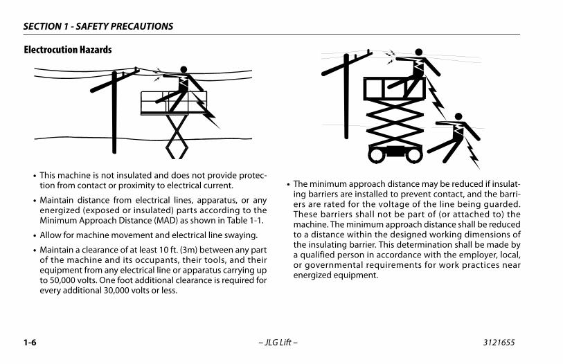
m approach distance may be reduced if insulat- are installed to prevent contact, and the barri-d for the voltage of the line being guarded.
iers shall not be part of (or attached to) thee minimum approach distance shall be reducede within the designed working dimensions ofg barrier. This determination shall be made by
person in accordance with the employer, local,ental requirements for work practices near
quipment.
– JLG Lift –
trocution Hazards
This machine is not insulated and does not provide protec-tion from contact or proximity to electrical current.
Maintain distance from electrical lines, apparatus, or anyenergized (exposed or insulated) parts according to theMinimum Approach Distance (MAD) as shown in Table 1-1.
Allow for machine movement and electrical line swaying.
Maintain a clearance of at least 10 ft. (3m) between any partof the machine and its occupants, their tools, and theirequipment from any electrical line or apparatus carrying upto 50,000 volts. One foot additional clearance is required forevery additional 30,000 volts or less.
• The minimuing barriersers are rateThese barrmachine. Thto a distancthe insulatina qualified or governmenergized e

SECTION 1 - SAFETY PRECAUTIONS
1-7
zards that the ground conditions are adequate to support
aximum tire load indicated on the tire load decals on the chassis adjacent to each wheel. Do not travel
upported surfaces.er must be familiar with the driving surface before. Do not exceed the allowable sideslope and graderiving.
t elevate platform or drive with platform elevatedn or near a sloping, uneven, or soft surface. Ensure
ne is positioned on a firm, level and smooth surface elevating platform or driving with the platform invated position. driving on floors, bridges, trucks, and other surfaces,allowable capacity of the surfaces.exceed the maximum work load as specified on them. Keep all loads within the confines of the platform, authorized by JLG.he chassis of the machine a minimum of 2 ft. (0.6m)oles, bumps, drop-offs, obstructions, debris, con- holes, and other potential hazards at the ground
operate the machine when wind conditions exceedcations shown in Section 5, Table 5-2 or as shown onacity placard on the platform billboard.
3121655 – JLG Lift –
DO NOT MANEUVER MACHINE OR PERSONNEL INSIDE PROHIBITED ZONE (MAD).ASSUME ALL ELECTRICAL PARTS AND WIRING ARE ENERGIZED UNLESS KNOWN OTH-ERWISE.
Tipping Ha• Ensure
the mlocatedon uns
• The usdrivingwhile d
• Do nowhile omachibeforethe ele
• Beforecheck
• Never platforunless
• Keep tfrom hcealedlevel.
• Do notspecifithe cap
Table 1-1. Minimum Approach Distances (M.A.D.)
VOLTAGE RANGE(Phase to Phase)
MINIMUM APPROACH DISTANCEin Feet (Meters)
0 to 50 KV 10 (3)
Over 50KV to 200 KV 15 (5)
Over 200 KV to 350 KV 20 (6)
Over 350 KV to 500 KV 25 (8)
Over 500 KV to 750 KV 35 (11)
Over 750 KV to 1000 KV 45 (14)NOTE: This requirement shall apply except where employer, local or govern-
mental regulations are more stringent.

SECTION 1 - SAFETY PRECAUTIONS
1-8 3121655
DO NO LE 5-2 OR AS SHOWN ON THE CAPACITY PLACARD ON THE PLAT-FORM
Only)
LAND CONDITIONS
ically.
smoke.
kin. Leaves rustle.
igs in constant motion.
aised. Small branches begin to move.
ion. Flags waving near horizontal. Umbrella
. Effort needed to walk against the wind.
es. Cars veer on road.
e.
– JLG Lift –
T OPERATE THE MACHINE WHEN WIND CONDITIONS EXCEED SPECIFICATIONS SHOWN IN SECTION 5, TAB BILLBOARD.
Table 1-2. Beaufort Scale (For Reference
BEAUFORT NUMBER
WIND SPEEDDESCRIPTION
mph m/s
0 0 0-0.2 Calm Calm. Smoke rises vert
1 1-3 0.3-1.5 Light air Wind motion visible in
2 4-7 1.6-3.3 Light breeze Wind felt on exposed s
3 8-12 3.4-5.4 Gentle breeze Leaves and smaller tw
4 13-18 5.5-7.9 Moderate breeze Dust and loose paper r
5 19-24 8.0-10.7 Fresh breeze Smaller trees sway.
6 25-31 10.8-13.8 Strong breeze Large branches in motuse becomes difficult.
7 32-38 13.9-17.1 Near Gale/Moderate Gale Whole trees in motion
8 39-46 17.2-20.7 Fresh Gale Twigs broken from tre
9 47-54 20.8-24.4 Strong Gale Light structure damag

SECTION 1 - SAFETY PRECAUTIONS
1-9
attempt to use the machine as a crane. Do not tie-offe to any adjacent structure. Never attach wire, cable,
similar items to platform.
t cover the platform sides or carry large surface-areain the platform when operating outdoors. The addi- such items increases the exposed wind area of thee.
t increase the platform size with unauthorized deckions or attachments.
cissor arm assembly or platform is caught so that onere wheels are off the ground, all persons must beed before attempting to free the machine. Use, forklift trucks, or other appropriate equipment toe machine and remove personnel.
nd Collision Hazardsved head gear must be worn by all operating and
personnel.
ands and limbs out of the scissor arm assembly dur-eration and when elevated without safety prop
ed.
for obstructions around machine and overheaddriving. Check clearances above, on sides, and bot- platform when lifting or lowering platform.
3121655 – JLG Lift –
• Never machinor any
• Do noitems tion ofmachin
• Do noextens
• If the sor moremovcranesstabiliz
Crushing a• Appro
ground
• Keep hing opengag
• Watchwhen tom of

SECTION 1 - SAFETY PRECAUTIONS
1-10 3121655
•
•
•
•
f stopping distances in all drive speeds. Whenigh speed, switch to low speed before stopping.s in low speed only.
high speed drive in restricted or close quartersving in reverse.
reme caution at all times to prevent obstaclesg or interfering with operating controls and per-
latform.
operators of other overhead and floor levelre aware of the aerial work platform’s presence.power to overhead cranes. Barricade floor area.
ate over ground personnel. Warn personnel notnd, or walk under a raised platform. Positionn floor as necessary.
– JLG Lift –
During operation, keep all body parts inside platform rail-ing.
Always post a lookout when driving in areas where vision isobstructed.
Keep non-operating personnel at least 6 ft. (1.8m) awayfrom machine during all operations.
Under all travel conditions, the operator must limit travelspeed according to conditions of ground surface, conges-tion, visibility, slope, location of personnel, and other fac-tors.
• Be aware odriving in hTravel grade
• Do not use or when dri
• Exercise extfrom strikinsons in the p
• Ensure thatmachines aDisconnect if necessary
• Do not operto work, stabarricades o

SECTION 1 - SAFETY PRECAUTIONS
1-11
established by a qualified person and must be fol- ensure that the machine is safe.
ce Hazardsff power to all controls and ensure that all movingre secured from inadvertent motion prior to per-
g any adjustments or repairs.
work under an elevated platform until it has beenwered to the full down position, if possible, or other-pported and restrained from movement with appro-
safety props, blocking, or overhead supports.
T attempt to repair or tighten any hydraulic hoses ors while the machine is powered on or when thelic system is under pressure.
relieve hydraulic pressurell hydraulic circuits beforeing or removing hydraulicnents.
T use your hand to check forUse a piece of cardboard or to search for leaks. Wear to help protect hands fromg fluid.
replacement parts or components are identical orlent to original parts or components.
3121655 – JLG Lift –
1.4 TOWING, LIFTING, AND HAULING• Never allow personnel in platform while towing, lifting, or
hauling.
• This machine should not be towed, except in the event ofemergency, malfunction, power failure, or loading/unload-ing. Refer to emergency towing procedures.
• Ensure platform is fully retracted and completely empty oftools prior to towing, lifting or hauling.
• When lifting machine with a forklift, position forks only atdesignated areas of the machine. Lift with a forklift of ade-quate capacity.
• Refer to Section 3 for lifting information.
1.5 MAINTENANCE
This sub-section contains general safety precautions whichmust be observed during maintenance of this machine. Addi-tional precautions to be observed during machine mainte-nance are inserted at the appropriate points in this manualand in the Service and Maintenance Manual. It is of utmostimportance that maintenance personnel pay strict attentionto these precautions to avoid possible injury to personnel ordamage to the machine or property. A maintenance program
must belowed to
Maintenan• Shut o
parts aformin
• Never fully lowise supriate
• DO NOfittinghydrau
• Alwaysfrom aloosencompo
• DO NOleaks. paperglovessprayin
• Ensureequiva

SECTION 1 - SAFETY PRECAUTIONS
1-12 3121655
•
•
•
•
MODMAD
sonnect batteries when servicing electrical com-when performing welding on the machine.
w smoking, open flame, or sparks near batteryging or servicing.
act tools or other metal objects across the bat-ls.
r hand, eye, and face protection when servicingsure that battery acid does not come in contact
clothing.
HIGHLY CORROSIVE. AVOID CONTACT WITH SKIN ANDIMES. IMMEDIATELY RINSE ANY CONTACTED AREA WITH
SEEK MEDICAL ATTENTION.
eries only in a well ventilated area.
illing the battery fluid level. Add distilled water only after the batteries are fully charged.
– JLG Lift –
Never attempt to move heavy parts without the aid of amechanical device. Do not allow heavy objects to rest in anunstable position. Ensure adequate support is providedwhen raising components of the machine.
Use only approved non-flammable cleaning solvents.
Do not replace items critical to stability, such as batteries orsolid tires, with items of different weight or specification.Do not modify unit in any way to affect stability.
Reference the Service and Maintenance Manual for theweights of critical stability items.
IFICATION OR ALTERATION OF AN AERIAL WORK PLATFORM SHALL BEE ONLY WITH PRIOR WRITTEN PERMISSION FROM THE MANUFACTURER.
Battery Hazard• Always disc
ponents or
• Do not alloduring char
• Do not conttery termina
• Always weabatteries. Enwith skin or
BATTERY FLUID ISCLOTHING AT ALL TCLEAN WATER AND
• Charge batt
• Avoid overfto batteries

ITIES, MACHINE PREPARATION & INSPECTION
2-1
PREPARATION & INSPECTION
eans to avoid the hazards of unprotected electrical nductors.ecific job requirements or machine application.
pervisionmust be done under the supervision of a qualified an open area free of obstructions until the traineeloped the ability to safely control and operate the
esponsibilityator must be instructed that he/she has the responsi- authority to shut down the machine in case of a
ion or other unsafe condition of either the machine site.
SECTION 2 - USER RESPONSIBIL
3121655 – JLG Lift –
SECTION 2. USER RESPONSIBILITIES, MACHINE
2.1 PERSONNEL TRAININGThe aerial platform is a personnel handling device; so it is nec-essary that it be operated and maintained only by trained per-sonnel.
Persons under the influence of drugs or alcohol or who aresubject to seizures, dizziness or loss of physical control mustnot operate this machine.
Operator TrainingOperator training must cover:
1. Use and limitations of the controls in the platform and at the ground, emergency controls and safety systems.
2. Control labels, instructions, and warnings on the machine.
3. Rules of the employer and government regulations.4. Use of approved fall protection device.5. Enough knowledge of the mechanical operation of
the machine to recognize a malfunction or potential malfunction.
6. The safest means to operate the machine where over-head obstructions, other moving equipment, and obstacles, depressions, holes, drop-offs.
7. Mco
8. Sp
Training SuTraining person inhas devemachine.
Operator RThe operbility andmalfunctor the job

SECTION 2 - USER RESPONSIBILITIES, MACHINE PREPARATION & INSPECTION
2-2 3121655
2.2The mended by JLG Industries, Inc. Consult local reg-ulat ections and maintenance must be increased asnec chine is used with increased frequency, or if themac
Table
Service Qualification Reference
Pre ser or Operator Operation and Safety Manual
Pre(se
ualified JLG echanic
Service and Maintenance Manual and applicable JLG inspection form
Fre ualified JLG echanic
Service and Maintenance Manual and applicable JLG inspection form
AnnIns(se
actory Trainedervice Technician Recommended)
Service and Maintenance Manual and applicable JLG inspection form
Pre ualified JLG echanic
Service and Maintenance Manual
NO s.
JLG HO HAS SUCCESSFULLY COMPLETED THE JLG SERVICETR
– JLG Lift –
PREPARATION, INSPECTION, AND MAINTENANCE table below covers the periodic machine inspections and maintenance recomions for further requirements for aerial work platforms. The frequency of inspessary when the machine is used in a harsh or hostile environment, if the mahine is used in a severe manner.
Table 2-1. Inspection and Maintenance
Type Frequency PrimaryResponsibility
-Start Inspection Before using each day; or whenever there’s an Operator change.
User or Operator U
-Delivery Inspectione note below)
Before each sale, lease, or rental delivery. Owner, Dealer, or User QM
quent Inspection In service for 3 months or 150 hours, whichever comes first; or Out of service for a period of more than 3 months; or Purchased used.
Owner, Dealer, or User QM
ual Machinepectione note below)
Annually, no later than 13 months from the date of prior inspection.
Owner, Dealer, or User FS(
ventative Maintenance At intervals as specified in the Service and Mainte-nance Manual.
Owner, Dealer, or User QM
TE: Inspection forms are available from JLG. Use the Service and Maintenance Manual to perform inspection
INDUSTRIES, INC. RECOGNIZES A FACTORY-TRAINED SERVICE TECHNICIAN AS A PERSON WAINING SCHOOL FOR THE SPECIFIC JLG PRODUCT MODEL.
NOTICE

ITIES, MACHINE PREPARATION & INSPECTION
2-3
s (ANSI markets only) is enclosed in the weather sistant storage container.
alk-Around” Inspection – Refer to Figure 2-1 attery – Charge as required.
el (Combustion Engine Powered Machines) – Add e proper fuel as necessary.gine Oil Supply (If equipped) - Ensure the engine
l level is at the full mark on the dipstick and the filler p is secure.uid Levels – Check the hydraulic oil level. Ensure draulic oil is added as required.
ccessories/Attachments - Refer to the accessories ction in this manual for specific inspection, opera-n, and maintenance instructions for accessories
at can be installed on this machine.nction Check – Once the “Walk-Around” Inspection
complete, perform a functional check of all systems an area free of overhead and ground level obstruc-ns. Refer to Section 3 for more specific operating
structions.
SECTION 2 - USER RESPONSIBIL
3121655 – JLG Lift –
Pre-Start InspectionThe Pre-Start Inspection should include each of the following:
1. Cleanliness – Check all surfaces for leakage (oil, fuel, or battery fluid) or foreign objects. Report any leakage to the proper maintenance personnel.
2. Structure - Inspect the machine structure for dents, damage, weld or parent metal cracks or other discrep-ancies.
3. Decals and Placards – Check all for cleanliness and legibility. Make sure none of the decals and placards are missing. Make sure all illegible decals and placards are cleaned or replaced.
4. Operation and Safety Manuals – Make sure a copy of the Operator and Safety Manual, AEM Safety Manual (ANSI markets only), and ANSI Manual of Responsibili-
tiere
5. “W6. B7. Fu
th8. En
oica
9. Flhy
10. Asetioth
11. Fuisintioin
Parent Metal Crack Weld Crack

SECTION 2 - USER RESPONSIBILITIES, MACHINE PREPARATION & INSPECTION
2-4 3121655
FunPerf
he platform control console:sure that the control console is firmly secured
the proper location. eck that all guards protecting the function con-
ol switches and controllers are in place.perate all functions and check all limiting andtout switches.sure that all machine functions are disabled
hen the Emergency Stop Button is depressed. he platform in the transport (stowed) position:rive the machine on a grade, not to exceed theted gradeability, and stop to ensure the brakesld.eck the tilt indicator light to ensure propereration. The light should be illuminated when
ted.
– JLG Lift –
ction Checkorm the Function Check as follows:
1. From the ground control console with no load in the platform:a. Check that all guards protecting the function con-
trol switches and controllers are in place.b. Operate all functions and check all limiting and
cutout switches.c. Check manual descent.d. Ensure that all machine functions are disabled
when the Emergency Stop Button is depressed.
2. From ta. En
inb. Ch
trc. O
cud. En
w3. With t
a. Draho
b. Choptil

ITIES, MACHINE PREPARATION & INSPECTION
2-5
r Japanese specification machines labeled "Ministry ofbor Notification #70," the Tilt Setting is 5 degrees (frontback and side to side) regardless of elevated platformight.
ble 2-3. High Drive Speed Cutout Height
del High Drive Speed Cutout Height
0ES 54 in. 1.4 m
2ES 66 in. 1.7 m
2ES 76 in. 1.9 m
6ES 76 in. 1.9 m
6ES 76 in. 1.9 m
SECTION 2 - USER RESPONSIBIL
3121655 – JLG Lift –
NOTE: FoLato he
Table 2-2. Tilt Activation vs. Height
ModelTilt Setting
(front to back)Tilt Setting
(side to side)Maximum Deck
ElevationDegrees Feet Meters
1930ES 3
1.5 18.75 (Full) 5.72 14 4.3
2.5 11 3.43 9 2.7
2032ES 3
1.5 20 (Full) 62 15 4.5
2.5 12 3.73 10 3
2632ES 3
1.5 25.4 (Full) 7.72 20 6
2.5 16 4.93 13 4
2646ES 32 26 (Full) 7.9
2.5 22 6.73 20 6
3246ES 32 31.75 (Full) 9.7
2.5 22 6.73 20 6
Ta
Mo
193
203
263
264
324

SECTION 2 - USER RESPONSIBILITIES, MACHINE PREPARATION & INSPECTION
2-6 3121655
on - Sheet 1
– JLG Lift –
Figure 2-1. Daily Walk-Around Inspecti

ITIES, MACHINE PREPARATION & INSPECTION
2-7
ls and Tires - Properly secured, no missing lug nuts. to Section 6, Tires and Wheels. Inspect wheels for ge and corrosion.le Protection System - See Inspection Note
ry Compartment - Proper electrolyte level.al Descent - See Inspection Noten - See Inspection Note
y Angle Switch - See Inspection Noted Controls - Placard secure and legible, control
hes return to neutral position, emergency stop functions properly. Control markings legible.ulic Pump/Motor, Control Valve Installation - No ported wires or hoses; no damaged or broken
- See Inspection Notelinder - See Inspection Notele, Tie Rod, Drive Motor and Steer Linkage (left - See Inspection Note Arms, Pivot Pins and Sliding Wear Pads (Not n) - See Inspection Noterm/Handrail Installation (Not Shown) - See Inspec-ote
tion - Sheet 2
SECTION 2 - USER RESPONSIBIL
3121655 – JLG Lift –
GeneralBegin the “Walk-Around Inspection” at Item 1, as noted onthe diagram. Continue Left (counterclockwise viewed fromtop) checking each item in sequence for the conditionslisted in the following checklist.
TO AVOID POSSIBLE INJURY, BE SURE MACHINE POWER IS “OFF” DURING“WALK-AROUND INSPECTION”.
NOTICEDO NOT OVERLOOK VISUAL INSPECTION OF CHASSIS UNDERSIDE. CHECK-ING THIS AREA OFTEN RESULTS IN DISCOVERY OF CONDITIONS WHICHCOULD CAUSE EXTENSIVE MACHINE DAMAGE.
INSPECTION NOTE: On each item, make sure there are no looseor missing parts, that they are securely fastened, and that no visi-ble damage exists in addition to any other criteria mentioned.
1. Platform Control Console - Placard secure and legible, control lever and switches return to neutral, control lever lock and emergency stop switch function properly, man-ual in storage box.
2. Steer Cylinder - See Inspection Note3. Spindle, Tie Rod, Drive Motor and Steer Linkage (left
front) - See Inspection Note
4. WheeReferdama
5. Potho6. Batte7. Manu8. Beaco9. Rotar
10. Grounswitcswitch
11. Hydraunsupwires
12. Lift Cy13. Spind
front)15. Sizzor
Show16. Platfo
tion N
Figure 2-2. Daily Walk-Around Inspec

SECTION 2 - USER RESPONSIBILITIES, MACHINE PREPARATION & INSPECTION
2-8 3121655
1. Pothole Switch (Typical on oppo-site side of machine)
2. Rotary Angle Switch
– JLG Lift –
Figure 2-3. Switch Locations

NE CONTROLS, INDICATORS AND OPERATION
3-1
TORS AND OPERATION
CRIPTIONe is a self-propelled aerial work platform on top of
g ‘scissor arm’ mechanism. The Scissor Lift’s intendedo position personnel with their tools and supplies atove ground level. The machine can be used to reachlocated above machinery or equipment positionedvel.
ssor Lift has a primary operator Control Station in theom this Control Station, the operator can drive andachine in both forward and reverse directions, raisehe platform and, if equipped, operate the poweredsion. The machine has a Ground Control Stationoverride the Platform Control Station. Ground Con-e lift up and down. Ground Controls are to be usedemergency to lower the platform to the ground
operator in the platform be unable to do so.
platform extension capacities are 250 lb (120 kg).
SECTION 3 - MACHI
3121655 – JLG Lift –
SECTION 3. MACHINE CONTROLS, INDICA
3.1 GENERAL
NOTICESINCE THE MANUFACTURER HAS NO DIRECT CONTROL OVER MACHINE APPLI-CATION AND OPERATION, CONFORMANCE WITH GOOD SAFETY PRACTICES INTHESE AREAS IS THE RESPONSIBILITY OF THE USER AND HIS OPERATINGPERSONNEL.This section provides the necessary information needed tounderstand control functions. Included in this section are theoperating characteristics and limitations, and functions and pur-poses of controls and indicators. It is important that the userread and understand the proper procedures before operatingthe machine. These procedures will aid in obtaining optimumservice life and safe operation.
3.2 DESThis machinan elevatinpurpose is tpositions abwork areas at ground le
The JLG Sciplatform. Frsteer the mand lower tdeck extenwhich will trols operatonly in an should the
NOTE: All

SECTION 3 - MACHINE CONTROLS, INDICATORS AND OPERATION
3-2 3121655
3.3
GenA thitatiusemen
PlaImpthe TANvariof pandtion
CapRaisplat
s originally manufactured by JLG and operatedcapacity on a smooth, firm and level supportings a stable aerial platform for all platform posi-
M LOADINGaximum rated load capacity is shown on a plac-he platform and is based upon the following cri-
achine is positioned on a firm, uniform surface.king devices are engaged.o Section 6 for the maximum platform capacity.
portant to remember that the load should bedistributed on the platform. The load should benear the center of the platform when possible.
– JLG Lift –
OPERATING CHARACTERISTICS AND LIMITATIONS
eralorough knowledge of the operating characteristics and lim-ons of the machine is always the first requirement for anyr, regardless of user’s experience with similar types of equip-
t.
cardsortant points to remember during operation are provided atcontrol stations by DANGER, WARNING, CAUTION, IMPOR-T and INSTRUCTION placards. This information is placed atous locations for the express purpose of alerting personnelotential hazards constituted by the operating characteristics load limitations of the machine. See foreword for defini-s of the above placards.
acitiesing platform above horizontal with or without any load inform, is based on the following criteria:
1. Machine is positioned on a smooth, firm and level sur-face.
2. Load is within manufacturer’s rated capacity.3. All machine systems are functioning properly.
StabilityThis machine, awithin its rated surface, providetions.
3.4 PLATFORThe platform mard located on tteria:
1. The m2. All bra3. Refer t
NOTE: It is imevenly placed

NE CONTROLS, INDICATORS AND OPERATION
3-3
Manual Descent T-Handle AC Receptacle Plugms - Safety Proptorage Box
s. (All Models)
SECTION 3 - MACHI
3121655 – JLG Lift –
1. Platform Control Station2. Ground Control Station3. MDI Indicator and Brake Release Button4. Battery Charger AC Plug
5. Platform6. Platform7. Scissor Ar8. Manual S
Figure 3-1. Location of Machine Control

SECTION 3 - MACHINE CONTROLS, INDICATORS AND OPERATION
3-4 3121655
3.5
Ope
NOT
ONLYOUTNONTERY
ALWCON
DO N
DO NCHADAM
Themac
battery charger, the charger will automatically n and go through a short LED indicator self-test. ’s will flash in sequence for two seconds.tteries are fully charged when green light on
ound control battery charger status panel (2), is ated.
– JLG Lift –
BATTERY CHARGING
ration
E: Be sure that machine is parked in a well ventilated areabefore charging begins.
PLUG THE CHARGER INTO A PROPERLY INSTALLED AND GROUNDEDLET. DO NOT USE GROUND ADAPTORS OR MODIFY PLUG. DO NOT TOUCH-INSULATED PORTION OF OUTPUT CONNECTOR OR NON-INSULATED BAT- TERMINAL.
AYS DISCONNECT THE AC SUPPLY BEFORE MAKING OR BREAKING THENECTIONS TO THE BATTERY BEFORE CHARGING.
OT OPEN OR DISASSEMBLE CHARGER.
OT OPERATE CHARGER IF THE AC SUPPLY CORD IS DAMAGED OR IF THERGER HAS RECEIVED A SHARP BLOW, BEEN DROPPED, OR OTHERWISEAGED IN ANY WAY.
battery charger AC plug (1) is located at the rear of thehine under the platform ladder.
1. Connect the charger to a grounded outlet.
2. On theturn oAll LED
3. The bathe grillumin

NE CONTROLS, INDICATORS AND OPERATION
3-5
arger Fault Codescurred during charging, the red "Fault" LED on the
d the ground control charger status panel (2) willa code. The number of flashes corresponds to theto Table 3-1, Battery Charger Flash Codes following.
h Codes
emoval
ot connected to charger or battery volts per cell is less than 0.5 VDC.
occur if the batteries are a larger capacity than the algorithm is
um voltage per cell level required for the charge to be started.
l temperature
al fault has been detected in the charger. This fault will nearly always rmined that the batteries and connections are not faulty and fault 6 is
the charger must be brought to a qualified service depot.
SECTION 3 - MACHI
3121655 – JLG Lift –
NOTE: If the charger is left plugged in, the charger will automati-cally restart a complete charge cycle if the batteries volt-age drops below a minimum voltage or 30 days haselapsed.
Battery ChIf a fault occharger anflash with error. Refer
Table 3-1. Battery Charger Flas
Flash(s) Fault Fault R
1 Battery voltage high Auto-recover - Indicates a high battery pack voltage
2 Battery voltage low Auto-recover - Indicates either a battery pack failure, battery pack nCheck the battery pack and connections
3 Charge time-out Indicates the batteries did not charge in the allowed time. This couldintended for or if the batteries are damaged old or in poor condition.
4 Check battery Indicates the batteries could not be trickle charged up to the minim
5 Over-temperature Auto-recover - Indicates charger has shut down due to high interna
6 QuiQ fault Indicates that the battery will not accept charge current, or an internbe set within the first 30 seconds of operation. Once it has been deteagain displayed after interrupting AC power for at least 10 seconds,

SECTION 3 - MACHINE CONTROLS, INDICATORS AND OPERATION
3-6 3121655
3.6
3
1. Right-Side Battery Compartment2. Diagnostic Trouble Code LCD3. Wrench Icon (Fault)4. Fault LED5. Battery Discharge Indicator (BDI)
ator
– JLG Lift –
MDI (MULTIFUNCTION DIGITAL INDICATOR)
1
24
5
5
55
Figure 3-2. Multifunction Digital Indic

NE CONTROLS, INDICATORS AND OPERATION
3-7
d on the MDI are Battery Discharge Indicators (BDI). LEDs indicate the level of charge in the batteries.
en the batteries are completely discharged, the LED in 0-25% range "red area" will flash.
I will convey the same information as the BDI on them control station. (see Figure 3-4., Platform Control)
normal driving conditions the BDI’s will be illumi- When a DTC exists (other than 00x DTC’s) the BDIill not be illuminated.
100%75%
50%
0-25%
Battery Charge/Discharge Indicator
SECTION 3 - MACHI
3121655 – JLG Lift –
MDI DescriptionLocated in the battery compartment on the left side of themachine is a Multifunction Digital Indicator (MDI). The purposeof the MDI is to display Diagnostic Trouble Codes (DTC) when afunctional problem occurs with the machine. The MDI isplugged into the diagnostic connector in the battery compart-ment.
When a problem occurs:
1. A Wrench Icon will display on the Diagnostic Trouble Code LCD display.
2. A three to five digit DTC will display on the Diagnostic Trouble Code LCD display, below the wrench icon.
NOTE: When more than one DTC exists, each DTC will be dis-played on the LCD for 3 seconds before changing to thenext DTC. Once the last active DTC is displayed, the displaywill recycle indefinitely until the DTC’s are corrected.
3. The red Fault LED will illuminate (this does not apply to 00x DTC’s; the Fault LED will not illuminate for these DTC’s).
NOTE: For DTC’s and descriptions, refer to Section 5.8, Diagnostictrouble codes (DTC) Check Tables Check Tables.
Also locateThese green
NOTE: Whthe
• The BDplatforStation
• Under nated.LEDs w

SECTION 3 - MACHINE CONTROLS, INDICATORS AND OPERATION
3-8 3121655
3.7
Con
DO NTHE PERFTHE
NOT
F/Ground Select
/Lower Switchtop Switchicator (If Equipped)
5. 10 Amp E-Stop Fuse6. Hour Meter7. Battery Charge Status LEDs
3-3. Ground Control Station Panel
– JLG Lift –
GROUND CONTROL STATION
trols and Indicators
OT OPERATE FROM GROUND CONTROL STATION WITH PERSONNEL INPLATFORM EXCEPT IN AN EMERGENCY.ORM AS MANY PRE-OPERATIONAL CHECKS AND INSPECTIONS FROM
GROUND CONTROL STATION AS POSSIBLE.
E: When the machine is shut down for overnight parking orbattery charging, the emergency stop and power selectswitches must be positioned to off to prevent draining thebatteries.
1. Platform/Ground Control SwitchA three position, key-operated power select switch supplies operating power to the platform or ground controls, as selected. When positioned to platform, the switch provides power to the emergency stop switch at the platform controls. When positioned to ground, the switch provides power to the ground control. The ground control emergency stop switch provides power to the key switch. With the power select switch in the center off position, power is shut off to both platform and ground controls.
1. Platform/OFSwitch
2. Platform Lift3. Emergency S4. Overload Ind
Figure

NE CONTROLS, INDICATORS AND OPERATION
3-9
attery Charger Status - This panel, located to the ht on the ground control box (), is designed to give
e operator an accurate read on the status of the bat-ry charger.. Green = Charge complete. Yellow = Charging in process. Red = Charging abnormal
scent Controll descent valve is used, in the event of total powerwer the platform using gravity. The manual descentcated at the rear of the machine, above the left rear handle is connected, by a cable, to the manuallve on the lift cylinder. Pulling the manual descentns the valve spool, lowering the platform.
Manual Descent - T-Handle Location
SECTION 3 - MACHI
3121655 – JLG Lift –
2. Platform Lift/Lower Switch - A three position, momentary contact Lift control switch provides rais-ing and lowering of the platform when positioned to up or down.
3. Emergency Stop Switch - A two-position, red, mush-room-shaped emergency stop switch, when posi-tioned to ON with the power selector switch positioned to ground, furnishes operating power to the ground control station. In addition, the switch can be used to turn off power to the function controls in the event of an emergency. Power is turned on by pull-ing the switch out (on), and is turned off by depressing switch.
4. Overload Indicator (LSS If Equipped) - Indicates the platform has been overloaded. An audible alarm will also signal when the platform is overloaded.
NOTE: If the Overload Indicator is illuminated, all functions willbe prevented from the platform controls. Reduce theweight in the platform to not exceed the rated workloadindicated on the capacity decal, or using the ground con-trols or manual descent control, fully lower the platform.
5. 10 Amp Fuse - Power feed to E-Stop button.6. Hour Meter - Keeps track of number of machine hours
of operation.
7. Brigthteabc
Manual DeThe manuafailure, to lohandle is lowheel. Thedescent vahandle ope

SECTION 3 - MACHINE CONTROLS, INDICATORS AND OPERATION
3-1 3121655
3.8
: *There is no indicator light equipped on asingle capacity ANSI machine.
1. Capacity Select Switch2. Indoor (CE) / Zone A Capacity (ANSI)*3. Outdoor (CE) / Zone B Capacity (ANSI)4. System Distress5. Battery Discharge Indicator6. Tilt Indicator7. Overload Indicator (LSS - If Equipped)8. Lift/Drive Select Switch9. Horn
10. Steer Switch11. Controller12. Black/White Directional Arrow13. Emergency Stop Switch14. Trigger Switch15. Tilt Alarm Warning Horn (not shown, located
on front of box)
0 – JLG Lift –
PLATFORM CONTROL STATION
NOTE
Figure 3-4. Platform Control Station

NE CONTROLS, INDICATORS AND OPERATION
3-11
pacity Select Switch - On model 2632ES/3246ES achines this switch is used to choose allowable pacity zone. On all CE machines, except the 2632ES, is switch is used to select either indoor or outdoor pacity zone.door (CE) / Zone A Capacity (ANSI/
US) - This indicator light will be illumi-ted when the Indoor (CE) or Zone A NSI/AUS) capacity is selected.utdoor (CE) / Zone B Capacity (ANSI/US) - This indicator light will be illumi-ted when the Outdoor (CE) or Zone B NSI/AUS) capacity is selected.stem Distress Indicator - This indica-r will light up with a fault flash code at will determine where a problem, ithin the system, exists.attery Discharge Indicator DI) - This set of lights is signed to let the operator ow the condition of the bat-ries.lt Indicator Warning Light - red warning light on the control panel at illuminates when the chassis is on a
SECTION 3 - MACHI
3121655 – JLG Lift –
NOTE: The platform control indicator panel uses different shapedsymbols to alert the operator to different types of opera-tional situations that could arise. The meaning of thosesymbols are explained below.
1. Camcathca
2. InAna(A
3. OAna(A
4. Sytothw
5. B(Bdeknte
6. TiAth
Indicates a potentially hazardous situation,which if not corrected, could result in seriousinjury or death. This indicator will be red.
Indicates an abnormal operating condition,which if not corrected, may result in machineinterruption or damage. This indicator will beyellow.
Indicates important information regarding theoperating condition, i.e. procedures essential forsafe operation. This indicator will be green withthe exception of the capacity indicator whichwill be green or yellow depending upon platformposition.

SECTION 3 - MACHINE CONTROLS, INDICATORS AND OPERATION
3-1 3121655
NOT
Switch - The steer switch is a operated switch located at the
the control handle. Depressing itch to the right will steer the s to the right. Depressing the to the left will steer the wheels to t.oller - The control handle controls unctions: drive, lift, and steer. The nd lift switch must be selected prior to moving ntrol handle.electing the drive function, moving the control forward will drive the machine forward and
g the control handle backwards will drive the ne backward.electing the lift function, moving the control backward will raise the platform and moving
ntrol handle forward will lower the platform. eed on all selected functions is proportionally lled by the distance of travel of the hand con-
. The thumb-operated steer switch on top of the ontroller activates the steer wheels in the direc-tivated (right or left).
2 – JLG Lift –
slope greater than what the machine is programmed for.
7. Overload Indicator (LSS If Equipped) - Indicates the platform has been over-loaded. An audible alarm will also signal when the platform is overloaded.
E: If the Overload Indicator is illuminated, allfunctions will be prevented from the platform controls.Reduce the weight in the platform to not exceed the ratedworkload indicated on the capacity decal, or using theground controls or manual descent control, fully lower theplatform.
8. Lift/Drive Select - This toggle switch is used to select either drive or lift. After selecting a function, the controller must be moved in the proper direction in order to activate that function. The func-tion must be selected with the joystick in the neu-tral position. Otherwise, the function select will not occur.
9. Horn - This push-button switch, when activated, permits the operator to warn jobsite personnel when the machine is operating in the area.
10. Steer thumbtop ofthe swwheelswitchthe lef
11. Contrthree fdrive athe coAfter shandlemovinmachiAfter shandlethe coThe spcontrotrollerhand ction ac

NE CONTROLS, INDICATORS AND OPERATION
3-13
DICATOR WARNING LIGHT OR HORN IS ACTIVATED WHEN PLAT-SED, LOWER PLATFORM COMPLETELY, THEN REPOSITIONHAT IT IS LEVEL BEFORE RAISING PLATFORM.
lt Alarm Warning Horn - Located on the front of the atform control box, the Tilt Alarm Warning Horn is tivated when the chassis is on a slope greater than hat the machine is programmed for and the plat-rm is elevated.
machines are equipped with a tilt interlock which cutst drive and lift up functions when chassis is on a slopeater than what is allowable for the machine and thetform is elevated.
ER” WITHOUT COMPLETELY RETRAC TING THE PLATFORM
ATE MACHINE IF HIGH DRIVE SPEED OPERATES WHEN PLAT-ED ABOVE THE STOWED POSITION.
SECTION 3 - MACHI
3121655 – JLG Lift –
12. Black/White Directional Decal - This decal indicates the proper direction to mount the platform control box, the black arrow must point to the front of the machine. The black/white arrow also indicates the direction to move the joystick control per the lift/drive selector switch decal for the lift and drive select functions.
13. Emergency Stop Switch - A two-position, red, mushroom-shaped emergency stop switch functions to provide power to the platform con-trol station and also to turn off power to the platform function controls in the event of an emergency. With the power selector switch positioned to platform, power is turned on by pulling the switch out (on), and is turned off by pushing the switch in (off ).
14. Trigger Switch - This switch is located on the front of the controller. The trigger switch acts as an enable and must be depressed when operating the drive, steer and lift functions. When released, the function being operated will stop.
IF THE TILT INFORM IS RAIMACHINE SO T
15. Tiplacwfo
NOTE: Allougrepla
DO NOT “LOWEXTENSION.
DO NOT OPERFORM IS RAIS

SECTION 3 - MACHINE CONTROLS, INDICATORS AND OPERATION
3-1 3121655
3.9
ONLYOBS
NOT
Rai
achine is equipped with a footswitch (Japanese or Specification Only), the footswitch must beed in conjunction with the trigger switch, locatedontroller.
RM AREA IS FREE OF PERSONNEL PRIOR TO LOWERING
chine is equipped with a descent alarm which wills the platform is being lowered (CE Optional).
rating from the ground controls, position the itch to down and hold until desired elevation is ed or until platform is fully lowered.rating from the platform controls, select lift on squeeze the trigger switch and push the con- forward (down) and hold until desired elevation hed or until platform is fully lowered. The lift works in conjunction with the enable switch. ing the trigger switch will stop the function
operated.
4 – JLG Lift –
PLATFORM OPERATION
RAISE PLATFORM ON A FIRM, LEVEL AND SMOOTH SURFACE FREE OFTRUCTIONS AND HOLES.
E: When selecting between the Lift/Drive functions, the con-troller must be in the neutral position for 3 seconds beforethe function change is effective. The machine is inopera-ble at this point.
sing1. If the machine is shut down, place the power selector
switch at the ground control station, to the desired position (platform or ground operation).
2. Position both the ground and platform control emer-gency stop switches to the "ON" position.
3. If operating from the ground controls, position the lift switch to up and hold until desired elevation is achieved.
4. If operating from the platform controls, select lift function, squeeze and hold the trigger switch, move the controller backward (up) and hold until desired elevation is reached. The lift switch works in conjunc-tion with the enable switch. Releasing the trigger switch will stop the function being operated.
NOTE: If the mKoreandepresson the c
Lowering
ENSURE SCISSOR APLATFORM.
NOTE: The masound a
1. If opelift swachiev
2. If opefunctitrolleris reacswitchReleasbeing

NE CONTROLS, INDICATORS AND OPERATION
3-15
GRADES OR SIDESLOPES EXCEEDING THOSE SPECIFIED. REFER-3-5., GRADE AND SIDESLOPE - DRIVING - PLATFORM STOWED.
wardace power selector switch at ground control station "Platform."sition emergency stop switch at platform control
ation to "On" position.lect "Drive" on the drive/lift select switch.ueeze controller (joystick), depressing trigger on
ont of joystick, and move joystick forward for dura-n of travel. The drive system is proportional so for ditional drive speed, push the joystick further in the
rection of travel. Releasing the trigger will stop the nction being operated.
eversesition power selector switch at ground control sta-n to "Platform."sition emergency stop switch at platform control
ation to "On" position.ueeze joystick, depressing trigger on front of joy-
ick, and move joystick backward (reverse) for dura-n of travel. The drive system is proportional so for ditional drive speed, push the joystick further in the
rection of travel. Releasing the trigger will stop the nction being operated.
SECTION 3 - MACHI
3121655 – JLG Lift –
Arm Guards (If equipped)If the machine is equipped with electronic arm guards, the plat-form will stop lowering at a predetermined height and themachine’s beacons will flash at a different rate to warn groundpersonnel, machine lowering can continue after a three (3) sec-ond delay. Once the lowering function is re-engaged an audiblealarm will sound. After a one and a half (1.5) second delay theplatform will continue lowering.
DO NOT ‘LOWER’ WITHOUT COMPLETELY RETRACTING THE PLATFORMEXTENSION.
SteeringTo steer the machine, the thumb operated steer control switchon the platform controller handle is positioned to the right fortraveling right, or to the left for traveling left. When released, theswitch will return to the center-off position and the wheels willremain in the previously selected position. To return the wheelsto the straightened position, the switch must be activated in theopposite direction until the wheels are centered.
Driving
DO NOT DRIVE WITH PLATFORM RAISED EXCEPT ON A SMOOTH, FIRM ANDLEVEL SURFACE FREE OF OBSTRUCTIONS AND HOLES. TO AVOID LOSS OFTRAVEL CONTROL OR UPSET ON GRADES AND SIDESLOPES, DO NOT DRIVE
MACHINE ON ENCE FIGURE
Driving For1. Pl
to2. Po
st3. Se4. Sq
frtioaddifu
Driving in R1. Po
tio2. Po
st3. Sq
sttioaddifu

SECTION 3 - MACHINE CONTROLS, INDICATORS AND OPERATION
3-1 3121655
tform Stowed
6 – JLG Lift –
Figure 3-5. Grade and Sideslope - Driving - Pla

NE CONTROLS, INDICATORS AND OPERATION
3-17
Mode:tion immediately stops and as long as the obstruc-mains present the machine cannot move until thed function is released, then the selected function isaged. The machine will move in the creep mode untilximity switch is no longer tripped.
Proximity SwitchesPlatform Rail Bumpers
3. Lower Perimeter Bumpers
Figure 3-6. Soft-Touch System
SECTION 3 - MACHI
3121655 – JLG Lift –
3.10 SOFT-TOUCH SYSTEM - (OPTION)The optional soft-touch system for scissor lifts consists of either;
• Platform mounted proximity switches
• Top platform rail and lower platform perimeter areas cov-ered with bumper padding
• Or a combination of both the above options together
The proximity switch option consists of proximity switchesmounted at each corner of the platform. These switches areconnected to a control box, when activated override normalplatform and machine movement.
OperationWhen any of the proximity switches is triggered:
• Machine functions are disabled, and alarm will sound (3tones)
In Platform Mode:• All motion immediately stops, and as long as the obstruc-
tion remains present the machine cannot move until theselected function is released, the horn button is pressedand held, and the selected function is re-engaged. Themachine will move in the creep mode until the proximityswitch is no longer tripped.
In Ground • All mo
tion reselectere-engthe pro
1.2.

SECTION 3 - MACHINE CONTROLS, INDICATORS AND OPERATION
3-1 3121655
3.1Thegivi203264of th
NOT
To releformdec
To rlevedeprails
Ma
tension Deckot Release Lever
3. Detent Locking Positions
. Platform Deck Extension. (All Models)
8 – JLG Lift –
1 PLATFORM DECK EXTENSION machine is equipped with a mechanically extendable deck,ng the operator better access to work areas. On the 1930ES/2ES/2632ES this extension adds 3 ft. (0.9 m) and on the6ES and 3246ES the extension adds 4 ft. (1.2 m) to the fronte platform.
E: There are three detent locking positions (3) on the exten-sion deck side rail kick plate. The extension deck releaselever only needs to be released when latched in each ofthose positions.
extend the deck (1) - press down on the foot operatedase lever (2) located on the right side kick plate of the plat-
. While depressing the release lever, grab the extensionk top handrails and slide the extendable deck out.
etract the deck - press down on the foot operated releaser located on the right side kick plate of the platform, Whileressing the release lever, grab the extension deck top hand- and slide the extendable deck in.
ximum capacity of the deck extension is 250 lbs (120 kg).
1. Ex2. Fo
Figure 3-7
NE CONTROLS, INDICATORS AND OPERATION
3-19
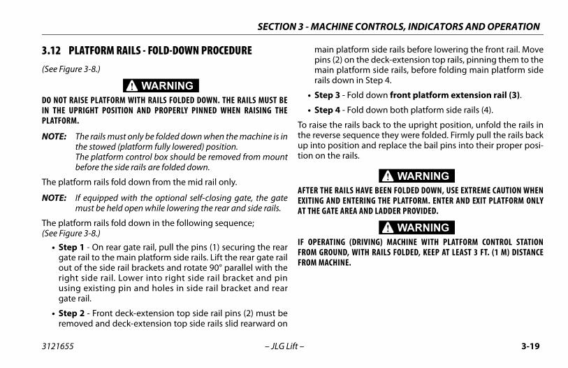
latform side rails before lowering the front rail. Move on the deck-extension top rails, pinning them to thelatform side rails, before folding main platform sidewn in Step 4.
- Fold down front platform extension rail (3).
- Fold down both platform side rails (4).
rails back to the upright position, unfold the rails in sequence they were folded. Firmly pull the rails backition and replace the bail pins into their proper posi- rails.
ILS HAVE BEEN FOLDED DOWN, USE EXTREME CAUTION WHEN ENTERING THE PLATFORM. ENTER AND EXIT PLATFORM ONLYAREA AND LADDER PROVIDED.
G (DRIVING) MACHINE WITH PLATFORM CONTROL STATIOND, WITH RAILS FOLDED, KEEP AT LEAST 3 FT. (1 M) DISTANCE
NE.
SECTION 3 - MACHI
3121655 – JLG Lift –
3.12 PLATFORM RAILS - FOLD-DOWN PROCEDURE(See Figure 3-8.)
DO NOT RAISE PLATFORM WITH RAILS FOLDED DOWN. THE RAILS MUST BEIN THE UPRIGHT POSITION AND PROPERLY PINNED WHEN RAISING THEPLATFORM.
NOTE: The rails must only be folded down when the machine is inthe stowed (platform fully lowered) position.The platform control box should be removed from mountbefore the side rails are folded down.
The platform rails fold down from the mid rail only.
NOTE: If equipped with the optional self-closing gate, the gatemust be held open while lowering the rear and side rails.
The platform rails fold down in the following sequence;(See Figure 3-8.)
• Step 1 - On rear gate rail, pull the pins (1) securing the reargate rail to the main platform side rails. Lift the rear gate railout of the side rail brackets and rotate 90° parallel with theright side rail. Lower into right side rail bracket and pinusing existing pin and holes in side rail bracket and reargate rail.
• Step 2 - Front deck-extension top side rail pins (2) must beremoved and deck-extension top side rails slid rearward on
main ppins (2)main prails do
• Step 3
• Step 4
To raise thethe reverseup into postion on the
AFTER THE RAEXITING ANDAT THE GATE
IF OPERATINFROM GROUNFROM MACHI

SECTION 3 - MACHINE CONTROLS, INDICATORS AND OPERATION
3-2 3121655
quence
1
0 – JLG Lift –
Figure 3-8. Platform Rails - Fold Down Se
3
2 4

NE CONTROLS, INDICATORS AND OPERATION
3-21
achine is not equipped with the anti-vandal coverstion to prevent unauthorized removal, the platform
trol station can be secured to it’s mount by placing ak through one or more of the holes located on it’s upperunting tabs.
re 3-9. Securing Control Station to Platform
SECTION 3 - MACHI
3121655 – JLG Lift –
3.13 PARKING AND STOWINGPark and stow the machine as follows:
1. Drive the machine to a reasonably well-protected and well-ventilated area.
2. Ensure the platform is fully lowered.3. Position the emergency stop switch to the "Off" posi-
tion.4. If necessary, cover the instruction placards, caution
and warning decals so that they will be protected from hostile environment.
5. Chock at least two wheels when parking the machine for an extended period of time.
6. Turn the power selector switch to "Off" and remove the key to disable the machine and prevent unauthor-ized use. The platform control station can also be secured to it’s mounting plate, see Figure 3-9.
7. If equipped with the optional anti-vandal package, the platform and ground control box assemblies may be covered and locked to prevent access.
NOTICEDO NOT OPERATE MACHINE FROM THE PLATFORM OR GROUND CONTROLSWITH THE ANTI-VANDAL COVERS CLOSED AND LOCKED IN PLACE.
NOTE: If mopconlocmo
Figu

SECTION 3 - MACHINE CONTROLS, INDICATORS AND OPERATION
3-2 3121655
3.1Whebe fmodtrailof tdowtieinlug.
LIFTOMMFROPROEVERPOTOPER
t the machine must be lifted, there is a forktruckat the rear of the machine. The machine can alsoa proper spreader bar and straps/chains. Refer-0., Lifting and Tie Down Diagram.
2 – JLG Lift –
4 TIE DOWN/LIFT LUGSn transporting the machine, the platform extension must
ully retracted and the platform fully lowered in the stowede with the machine securely tied down to the truck or
er deck. There are two tie-down/lift lugs located at the rearhe machine for lifting and tieing down. There is a single tie-n lug at the front of the machine. This lug is designed forg down only. Do not attempt to lift machine from the front
ING THE MACHINE FROM THE SIDES USING A FORK TRUCK IS NOT REC-ENDED BY JLG. IN THE EVENT THAT THE MACHINE NEEDS TO BE LIFTED
M THE SIDES CAUTION MUST BE USED TO AVOID JAMMING THE POT HOLETECTION BARS UP AGAINST THE FRAME.
Y TIME THE MACHINE IS LIFTED FORM THE SIDE, BE SURE AND TEST THE HOLE PROTECTION SYSTEM BEFORE THE MACHINE IS PUT BACK INTO
ATION.
3.15 LIFTINGIn the event thapocket located be lifted using ence Figure 3-1

NE CONTROLS, INDICATORS AND OPERATION
3-23
iagram
SECTION 3 - MACHI
3121655 – JLG Lift –
Figure 3-10. Lifting and Tie Down D

SECTION 3 - MACHINE CONTROLS, INDICATORS AND OPERATION
3-2 3121655
Z13 in. (33 cm)
13.5 in. (34.25 cm)13.5 in. (34.25 cm)
20.5 in. (52 cm)20.5 in. (52 cm)
art
4 – JLG Lift –
MODEL WHEELBASE X1930ES 63 in. (160 cm) 33.5 in. (83.7 cm)2032ES 73.9 in. (187.7 cm) 38.5 in. (13 cm)2632ES 73.9 in. (187.7 cm) 38.5 in. (13 cm)2646ES 82.32 in. (209.1 cm) 43.8 in. (108.6 cm)3246ES 82.32 in. (209.1 cm) 43.8 in. (108.6 cm)
Figure 3-11. Lifting and Tie Down Ch
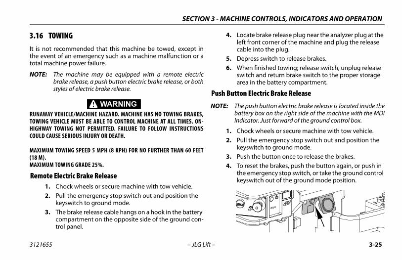
NE CONTROLS, INDICATORS AND OPERATION
3-25
cate brake release plug near the analyzer plug at the ft front corner of the machine and plug the release ble into the plug.
epress switch to release brakes.hen finished towing; release switch, unplug release itch and return brake switch to the proper storage
ea in the battery compartment.
n Electric Brake Release
e push button electric brake release is located inside thettery box on the right side of the machine with the MDIicator. Just forward of the ground control box.
ock wheels or secure machine with tow vehicle.ll the emergency stop switch out and position the yswitch to ground mode.sh the button once to release the brakes. reset the brakes, push the button again, or push in e emergency stop switch, or take the ground control yswitch out of the ground mode position.
SECTION 3 - MACHI
3121655 – JLG Lift –
3.16 TOWINGIt is not recommended that this machine be towed, except inthe event of an emergency such as a machine malfunction or atotal machine power failure.
NOTE: The machine may be equipped with a remote electricbrake release, a push button electric brake release, or bothstyles of electric brake release.
RUNAWAY VEHICLE/MACHINE HAZARD. MACHINE HAS NO TOWING BRAKES,TOWING VEHICLE MUST BE ABLE TO CONTROL MACHINE AT ALL TIMES. ON-HIGHWAY TOWING NOT PERMITTED. FAILURE TO FOLLOW INSTRUCTIONSCOULD CAUSE SERIOUS INJURY OR DEATH.
MAXIMUM TOWING SPEED 5 MPH (8 KPH) FOR NO FURTHER THAN 60 FEET(18 M).MAXIMUM TOWING GRADE 25%.
Remote Electric Brake Release1. Chock wheels or secure machine with tow vehicle.2. Pull the emergency stop switch out and position the
keyswitch to ground mode.3. The brake release cable hangs on a hook in the battery
compartment on the opposite side of the ground con-trol panel.
4. Loleca
5. D6. W
swar
Push Butto
NOTE: ThbaInd
1. Ch2. Pu
ke3. Pu4. To
thke

SECTION 3 - MACHINE CONTROLS, INDICATORS AND OPERATION
3-2 3121655
Mec
AFTEFROWITCAU
Figure 3-12. Manual Disengage
6 – JLG Lift –
hanical Brake Release1. Chock wheels or secure machine with tow vehicle.2. Ensure E-stop button is pushed in to the "OFF" posi-
tion.3. Remove the two cover bolts (2) and brake cover (1).4. Insert the cover bolts (2) into the two disengage
holes (3) in the brake housing, see item 3 in Figure 3-12., Manual Disengage.
5. Tighten down the cover bolts (2) and the brake on that drive motor will disengage.
6. Repeat this procedure on opposite wheel drive. With both drive motor brakes now disengaged, the machine can be moved manually.
7. After towing is complete, chock wheels and remove cover bolts (2) from disengage holes (3).
8. Reinstall brake cover (1).
R THE MACHINE IS TOWED, THE DISENGAGE BOLTS MUST BE REMOVEDM THE BRAKE DISENGAGE HOLES. THE BRAKES CANNOT BE ENGAGEDH THE DISENGAGE BOLTS IN THE BRAKE DISENGAGE HOLES. THIS WILLSE THE MACHINE TO ROLL WHEN PARKED ON AN INCLINE.

SECTION 4 - EMERGENCY PROCEDURES
4-1
OCEDURES
Control Station is located on the left side of theme. The controls on this panel provide the means
ng the platform controls and for controlling the plat- and down functions from the ground. Place the
ct switch in the ground position and operate the liftt up or down.
scentl descent valve is used, in the event of total powerwer the platform using gravity. The manual descentcated at the rear of the machine, above the left rear handle is connected, by a cable, to the manuallve on the lift cylinder. Pulling the manual descentns the valve spool, lowering the platform.
Manual Descent - T-Handle Location
3121655 – JLG Lift –
SECTION 4. EMERGENC Y PR
4.1 GENERALThis section provides information on the procedures to be fol-lowed and on the systems and controls to be used in the eventan emergency situation is encountered during machine opera-tion. Prior to operation of the machine and periodically thereaf-ter, the entire operating manual, including this section, shouldbe reviewed by all personnel whose responsibilities include anywork or contact with the machine.
Emergency Stop SwitchThese large red buttons, one located at the Ground Control Sta-tion and one at the Platform Control Station, will immediatelystop the machine when depressed.
CHECK MACHINE DAILY TO MAKE SURE EMERGENCY STOP BUTTON IS INPLACE AND THAT GROUND CONTROL INSTRUCTIONS ARE IN PLACE AND LEGI-BLE.GROUND CONTROL STATION
The Groundmachine frafor overridiform lift uppower seleswitch to lif
Manual DeThe manuafailure, to lohandle is lowheel. Thedescent vahandle ope

SECTION 4 - EMERGENCY PROCEDURES
4-2 3121655
4.2Use
KNOGromactionandthe
le to Control Machinete the machine from ground controls ONLY with sistance of other personnel and equipment s, overhead hoists, etc.) as may be required to remove the danger or emergency condition. qualified personnel on the platform may use the rm controls. DO NOT CONTINUE OPERATION IF ROLS DO NOT FUNCTION NORMALLY.s, forklift trucks or other equipment which may ilable are to be used to remove platform occu-and stabilize motion of the machine in case ne controls are inadequate or malfunction when
– JLG Lift –
EMERGENCY OPERATION of Ground Controls
NOTICEW HOW TO USE THE GROUND CONTROLS IN AN EMERGENCY SITUATION.und personnel must be thoroughly familiar with thehine operating characteristics and the ground control func-s. Training should include operation of the machine, review understanding of this section and hands-on operation ofcontrols in simulated emergencies.
Operator Unab1. Opera
the as(cranesafely
2. OtherplatfoCONT
3. Cranebe avapants machiused.

SECTION 4 - EMERGENCY PROCEDURES
4-3
DENT NOTIFICATIONtive that JLG Industries, Inc. be notified immediatelydent involving a JLG product. Even if no injury ormage is evident, the Product Safety and Reliability
t at the factory should be contacted by telephoned with all necessary details.
1-877-JLG-SAFE (554-7233) between the hours of:45 PM Eastern Standard time.
noted that failure to notify the Manufacturer of anolving a JLG Industries product within 48 hours ofcurrence may void any warranty consideration onlar machine.
3121655 – JLG Lift –
Platform Caught OverheadIf the platform becomes jammed or snagged in overhead struc-tures or equipment, do not continue operation of the machinefrom either the platform or the ground until the operator and allpersonnel are safely moved to a secure location. Only thenshould an attempt be made to free the platform using any nec-essary equipment and personnel. Do not operate controls tocause one or more wheels to leave the ground.
Righting of Tipped MachineA forktruck of suitable capacity or equivalent equipment shouldbe placed under the elevated side of the chassis, with a crane orother suitable lifting equipment used to lift the platform whilethe chassis is lowered by the forklift or other equipment.
Post-Incident InspectionFollowing any incident, thoroughly inspect the machine andtest all functions first from the ground controls, then from theplatform controls. Do not lift above 10 feet (3 meters) until youare secure that all damage has been repaired, if required, andthat all controls are operating correctly.
4.3 INCIIt is imperaof any inciproperty daDepartmenand provide
Contact at 8:00 AM - 4
It should beincident invsuch an octhat particu

SECTION 4 - EMERGENCY PROCEDURES
4-4 3121655
– JLG Lift –NOTES:

CIFICATIONS AND OPERATOR MAINTENANCE
5-1
OPERATOR MAINTENANCE
ications Available Specific to this Machine:
nd Maintenance Manual................ 3121656
d Parts Manuals:ES ........................................................... 3121275/2632ES ............................................... 3121682/3246ES ............................................... 3121275
SECTION 5 - GENERAL SPE
3121655 – JLG Lift –
SECTION 5. GENERAL SPECIFICATIONS AND
5.1 INTRODUCTIONThis section of the manual provides additional necessary infor-mation to the operator for proper operation and maintenanceof this machine.The maintenance portion of this section is intended as informa-tion to assist the machine operator to perform daily mainte-nance tasks only, and does not replace the more thoroughPreventive Maintenance and Inspection Schedule included inthe Service and Maintenance Manual.
Other Publ
Service a
Illustrate193020322646

SECTION 5 - GENERAL SPECIFICATIONS AND OPERATOR MAINTENANCE
5-2 3121655
5.2
s
2632ES 2646ES 3246ES
Max - Re 25% 25% 25%
Max- Re 5° 5° 5°
Max 25.5 ft7.75 m
26 ft7.9 m
32 ft9.8 m
Max AN CE 35 lb (832 kg) 2070 lb (939 kg)
2320 lb (1052 kg)2070 lb (939 kg)
2320 lb (1052 kg)
Gro 90 psi6.3 kg/cm2 )
87 psi(6.1 kg/cm2 )
87 psi(6.1 kg/cm2 )
Gro 6.3 kg/cm2
(90 psi)6.9 kg/cm2
(98 psi)6.9 kg/cm2
(98 psi)
Max 3.6 mph(5.7 kmh)
3 mph(4.8 kmh)
3 mph(4.8 kmh)
Max ph (12.5 m/s)or selection, see Table 5-2, Platform Capacities on page 5-5)
– JLG Lift –
OPERATING SPECIFICATIONS
Table 5-1. Operating Specification
Model 1930ES 2032ES
imum Stowed Travel Grade (Gradeability)fer to Figure 3-5. on page 3-16 25% 25%
imum Stowed Travel Grade (Sideslope)fer to Figure 3-5. on page 3-16 5° 5°
imum Platform Height 18.8 ft5.7 m
20 ft6 m
imum Tire Load:SI 1365 lb (620 kg)
1540 lb (699 kg)1660 (755)
1835 lb (832 kg) 18
und Bearing Pressure (ANSI) 109 psi (7.7 kg/cm2 )
81 psi(5.7 kg/cm2 ) (
und Bearing Pressure (CE) 8.7 kg/cm2
(123 psi)6.3 kg/cm2
(90 psi)
imum Drive Speed 3.5 mph(5.6 kmh)
3.6 mph(5.7 kmh)
imum Wind Speed 28 m(Depending on model, market, and indoor/outdo

CIFICATIONS AND OPERATOR MAINTENANCE
5-3
N/AN/AN/A
120 lb force (533 N)100 lb force (445 N)90 lb force (400 N)
N/AN/A
90 lb force (400 N)90 lb force (400 N)
N/AN/AN/A
150 lb force (667 N)N/AN/AN/AN/A
90 lb force (400 N)90 lb force (400 N)90 lb force (400 N)
N/AN/A
90 lb force (400 N)N/AN/A
N/AN/AN/A
150 lb force (667 N)105 lb force (467 N)90 lb force (400 N)45 lb force (200 N)
N/A90 lb force (400 N)90 lb force (400 N)
N/AN/A
45 lb force (200 N)
1900 psi (single)1900 psi (dual) 1900 psi 1900 psi
90° 90° 90°
73° 67° 67°
24V 24V 24V
4635 lbs (single)4610 lbs (dual) 4975 lbs 4975 lbs
tions
2632ES 2646ES 3246ES
SECTION 5 - GENERAL SPE
3121655 – JLG Lift –
Maximum Horizontal Manual Side Force: ANSI/CSA ANSI/CSA (Indoor) ANSI/CSA (Outdoor) ANSI/CSA (Zone A) ANSI/CSA (Zone B) CE (Indoor) CE (Outdoor) AUS (Indoor) AUS (Indoor Zone A) AUS (Indoor Zone B) AUS (Outdoor) AUS (Outdoor Zone A) AUS (Outdoor Zone B)
100 lb force (445 N)N/AN/AN/AN/A
90 lb force (400 N)45 lb force (200 N)90 lb force (400 N)
N/AN/A
45 lb force (200 N)N/AN/A
120 lb force (533 N)N/AN/AN/AN/A
90 lb force (400 N)45 lb force (200 N)90 lb force (400 N)
N/AN/A
45 lb force (200 N)N/AN/A
Maximum Hydraulic Pressure 1900 psi 1900 psi
Inside Steer Angle 90° 90°
Outside Steer Angle 69° 73°
Electrical System Voltage (DC) 24V 24V
Approximate Gross Machine Weight -ANSI/CSA 2710 lbs 3610 lbs
Table 5-1. Operating Specifica
Model 1930ES 2032ES

SECTION 5 - GENERAL SPECIFICATIONS AND OPERATOR MAINTENANCE
5-4 3121655
AppCE/A
02 kg (single)091 kg (dual) 2737 kg 2903 kg
App 02 kg (single)091 kg (dual) 2257 kg 2257 kg
Gro 5 in (12.7 cm)
Gro .75 in (1.9 cm)
s
2632ES 2646ES 3246ES
– JLG Lift –
roximate Gross Machine Weight -ustralia 1506 kg 1966 kg 21
2
roximate Gross Machine Weight - Japan 1229 kg 1637 kg 212
und Clearance with pot hole protection system up 3.5 in (8.9 cm)
und Clearance with pot hole protection system down 1 in (2.5 cm)
Table 5-1. Operating Specification
Model 1930ES 2032ES

CIFICATIONS AND OPERATOR MAINTENANCE
5-5
ies
AUSTRALIAN INDOOR OUTDOOR
ax rsons
MaxCapacity
Max Persons
Max Capacity
Max Persons
1 230 kg 2 120 kg 1
1 360 kg 2 160 kg 1
/A 230 kg 2 N/A N/A
/A 360 kg 2 N/A N/A
/A 230 kg 2 N/A N/A
2 450 kg 2 230 kg 2
1 450 kg 2 320 kg 1
1 320 kg 2 320 kg 1
SECTION 5 - GENERAL SPE
3121655 – JLG Lift –
Table 5-2. Platform Capacit
MODELANSI/CSA/JPN
CEINDOOR OUTDOOR
MaxCapacity
MaxPersons
Max Capacity
Max Persons
MaxCapacity
MPe
1930ES 500 lb (227 kg) 2 230 kg 2 120 kg
2032ES 800 lb (363 kg) 2 360 kg 2 160 kg
2632ESsingle cap
500 lb (227 kg) 2 230 kg 2 N/A N
2632ESdual cap.to 20 ft
800 lb (363 kg) 2 360 kg 2 N/A N
2632ESdual cap.to 26 ft
500 lb (227 kg) 2 230 kg 2 N/A N
2646ES 1000 lb (454 kg) 2 450 kg 2 230 kg
3246ES to 26 ft. Zone A1000 lb (454 kg)
2 450kg 2 320 kg
3246ES to 32 ft. Zone B700 lb
(317 kg)2 320kg 2 320 kg

SECTION 5 - GENERAL SPECIFICATIONS AND OPERATOR MAINTENANCE
5-6 3121655
Dim
2632ES 2646ES 3246ES
t meter feet meter feet meter
Pla .5 7.77 26 7.9 31.8 9.7
Pla 1.2 4 1.2 4 1.2
Wo 2 9.8 32 9.8 38 11.6
Ove 7 2.3 7.7 2.3 7.7 2.3
Ove 4 1.9 6.4 1.9 6.4 1.9
Rai 6 1.1 3.6 1.1 3.6 1.1
Ove 6 0.81 3.7 1.2 3.7 1.2
Ove 5 2.3 8.2 2.5 8.2 2.5
Ove .5 3.2 12.4 3.8 12.4 3.8
Pla 5 2.3 8.2 2.5 8.2 2.5
Pla 5 0.76 3.7 1.1 3.7 1.1
Pla 0.9 4.2 1.3 4.2 1.3
Wh in. 188 cm 82.3 in. 209 cm 82.3 in. 209 cm
– JLG Lift –
ensional Data
Table 5-3. Dimensions
Model 1930ES 2032ES
Unit of Measure feet meter feet meter fee
tform Height - Elevated 18.8 5.7 20 6 25
tform Height - Stowed 2.9 0.9 3.6 1.1 4
rking Height 25 7.6 26 7.9 3
rall Stowed Machine Height - Rails Up 6.5 2 7.2 2.2 7.
rall Stowed Machine Height - Rails Folded N/A N/A 6 1.8 6.
l Height (From platform floor) 3.6 1.1 3.6 1.1 3.
rall Machine Width 2.5 0.8 2.66 0.81 2.6
rall Machine Length - Deck Retracted 6 1.9 7.5 2.3 7.
rall Machine Length - Deck Extended 9 2.8 10.5 3.2 10
tform Size - Length 6.1 1.9 7.5 2.3 7.
tform Size - Width 2.5 0.8 2.5 0.8 2.
tform Extension Length 3 0.9 3 0.9 3
eelbase 63 in. 160 cm 74 in. 188 cm 74
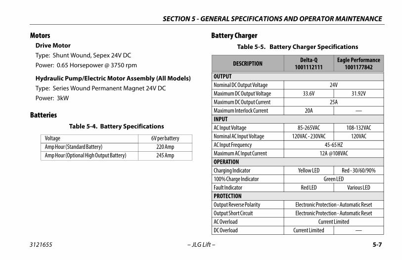
CIFICATIONS AND OPERATOR MAINTENANCE
5-7
argerble 5-5. Battery Charger Specifications
CRIPTION Delta-Q1001112111
Eagle Performance1001177842
tput Voltage 24VOutput Voltage 33.6V 31.92VOutput Current 25Arlock Current 20A —
ge 85-265VAC 108-132VACput Voltage 120VAC - 230VAC 120VACency 45-65 HZnput Current 12A @108VAC
ator Yellow LED Red - 30/60/90%Indicator Green LED
Red LED Various LED
e Polarity Electronic Protection - Automatic Resetircuit Electronic Protection - Automatic Reset
Current LimitedCurrent Limited —
SECTION 5 - GENERAL SPE
3121655 – JLG Lift –
MotorsDrive MotorType: Shunt Wound, Sepex 24V DC
Power: 0.65 Horsepower @ 3750 rpm
Hydraulic Pump/Electric Motor Assembly (All Models)Type: Series Wound Permanent Magnet 24V DC
Power: 3kW
Batteries
Battery Ch
Table 5-4. Battery Specifications
Voltage 6V per batteryAmp Hour (Standard Battery) 220 AmpAmp Hour (Optional High Output Battery) 245 Amp
Ta
DES
OUTPUTNominal DC OuMaximum DC Maximum DC Maximum InteINPUTAC Input VoltaNominal AC InAC Input FrequMaximum AC IOPERATIONCharging Indic100% Charge Fault IndicatorPROTECTIONOutput ReversOutput Short CAC OverloadDC Overload

SECTION 5 - GENERAL SPECIFICATIONS AND OPERATOR MAINTENANCE
5-8 3121655
Bat
MEOpeHou
T
AC IOut
Out
AC O
AC O
Out
DC I
Rem
CHANom
t Voltage 33 VDC
t Current 23 to 27 ADC
urrent 1 A
100 to 130 VAC
ge (AC) 120 VAC
54 to 66 Hz
Yellow LED
tor Green LED
Red LED
olarity 125 A Replaceable Fuse
uit Electronic Protection - Automatic Reset
20 A Internal Slow Blow Charger Fuse
Voltage Limited - Internally Controlled
ure –40° F to + 185° F(–40° C to + 85° C)
Shock and Water Resistant Aluminum
attery Charger/AC Inverter Specifications
– JLG Lift –
tery Charger/AC Inverter
DESCRIPTION 1001112111 1001177842CHANICALrating Temperature –22° F to +122° F (–30° C to +50° C)sing Shock and Water Resistant Aluminum
able 5-6. Battery Charger/AC Inverter Specifications
DESCRIPTION Xantrex1001093839
NVERTERput Power (Continuous) 1000 W
put Power (Surge) 3000 W
utput Current 36 A
utput Voltage 115 to 125 VAC
put Frequency 60 Hz
nput Voltage 21.2 to 29 VDC
ote ON/OFF Yes
RGERinal DC Output Voltage 28 VDC
Table 5-5. Battery Charger Specifications
Maximum DC Outpu
Maximum DC Outpu
Required Interlock C
Input Voltage (AC)
Nominal Input Volta
Input Frequency
OPERATIONCharging Indicator
100% Charge Indica
Fault Indicator
PROTECTIONOutput Reverse DC P
Output AC Short Circ
AC Overload
DC Overload
MECHANICAL
Operating Temperat
Housing
Table 5-6. B

CIFICATIONS AND OPERATOR MAINTENANCE
5-9
s
S 2646ES/3246ES
3 Gal. (11.3 L)
5.3 Gal (19.9 L)
ns
2632ES 2646ES 3246ES
406 mm x 125 mm
4000 lbs (1814 kg)
(142-163 Nm)
SECTION 5 - GENERAL SPE
3121655 – JLG Lift –
Capacities
Tires
Table 5-7. Fluid Capacitie
Model 1930ES/ 2032ES/2632E
Hydraulic Tank 2 Gal. (7.6 L)
2 Gal. (7.6 L)
Hydraulic System (Including Tank)
2.2 Gal (8.3 L)
2.8 Gal (10.6 L)
Table 5-8. Tire Specificatio
Model 1930ES 2032ES
Size 323mm x 100mm
Max Tire Load 2500 lbs (1134 kg)
Wheel Bolt Torque 105 - 120 ft lb

SECTION 5 - GENERAL SPECIFICATIONS AND OPERATOR MAINTENANCE
5-1 3121655
Crit
DO NSOLINOT
s
2ES 2646ES 3246ES
42 lbs (19 kg)
162 lbs (73.4 kg)
263 lbs (119 kg) 283 lbs (128 kg)
60 lbs (27 kg)66 lbs (30 kg)70 lbs (32 kg)
0 – JLG Lift –
ical Stability Weights
OT REPLACE ITEMS CRITICAL TO STABILITY, SUCH AS BATTERIES ORD TIRES, WITH ITEMS OF DIFFERENT WEIGHT OR SPECIFICATION. DO MODIFY UNIT IN ANY WAY TO AFFECT STABILITY.
Table 5-9. Critical Stability Weight
Component 1930 ES 2032ES 263
Wheel and Tire Assembly (each) 22 lbs (9.8 kg)
Wheel/Tire and Drive Assembly (each) 117 lbs (53 kg)
Lift Cylinder 176 lbs(80 kg) 205 lbs (93 kg)
Batteries: (each) 220 Amp 220 Amp (used with Inverter/Charger) 245 Amp
60 lbs (27 kg)66 lbs (30 kg)
N/A
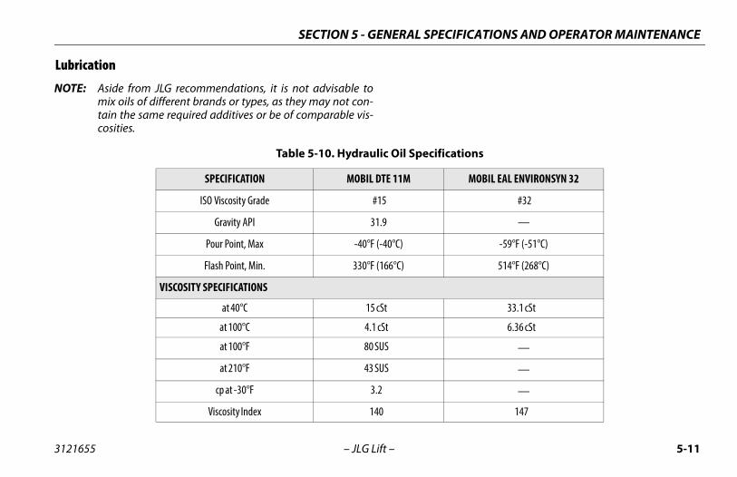
CIFICATIONS AND OPERATOR MAINTENANCE
5-11
ications
MOBIL EAL ENVIRONSYN 32
#32
—
-59°F (-51°C)
514°F (268°C)
33.1 cSt
6.36 cSt
—
—
—
147
SECTION 5 - GENERAL SPE
3121655 – JLG Lift –
Lubrication
NOTE: Aside from JLG recommendations, it is not advisable tomix oils of different brands or types, as they may not con-tain the same required additives or be of comparable vis-cosities.
Table 5-10. Hydraulic Oil Specif
SPECIFICATION MOBIL DTE 11M
ISO Viscosity Grade #15
Gravity API 31.9
Pour Point, Max -40°F (-40°C)
Flash Point, Min. 330°F (166°C)
VISCOSITY SPECIFICATIONS
at 40°C 15 cSt
at 100°C 4.1 cSt
at 100°F 80 SUS
at 210°F 43 SUS
cp at -30°F 3.2
Viscosity Index 140

SECTION 5 - GENERAL SPECIFICATIONS AND OPERATOR MAINTENANCE
5-1 3121655
5.3
1. Hydraulic Oil2. Lower Slide Pads3. Upper Slide Pads4. Scissor Arms - Safety Prop
2 – JLG Lift –
OPERATOR MAINTENANCE
Figure 5-1. Lubrication Diagram

CIFICATIONS AND OPERATOR MAINTENANCE
5-13
rocedure (1)be Point(s) - FIll Plug
pacity:
be - Hydraulic Oil
terval - Every 6 months
h the scissor lift on a flat and level surface and theform empty, elevate machine and swing safety prop of it’s stowed position. tinue to elevate the platform until the fill plug,ted on the right side of the tank attached to the lift
nder, is fully accessible.
CISSOR ARMS ARE PROPERLY SUPPORTED.
2632ES/2646ES/3246ES platforms will have to beed higher than the 1930ES and 2032ES in order toess the oil plug.
1930ES/2032ES/2632ES 2646ES/3246ES
2 Gal. (7.6 L) 3 Gal. (11.3 L)
SECTION 5 - GENERAL SPE
3121655 – JLG Lift –
Scissor Arms - Safety Prop
THE SAFETY PROP MUST BE USED WHENEVER MAINTENANCE PERFORMEDON THE MACHINE REQUIRES THE SCISSOR ARMS TO BE RAISED AND ONLYWITH NO LOAD IN THE PLATFORM.
To engage the safety prop, raise the platform, rotate the safetyprop from it’s stowed position located on the right side of themachine. Lower the platform until the safety prop rests on thedesignated safety prop rest, just above the center pin on thearm below.
To store the safety prop, raise the platform, rotate the safetyprop around and restore it back to its stowed position.
Oil Check P• Lu
• Ca
• Lu
• In
1. Witplatout
2. Conlocacyli
ENSURE THE S
NOTE: Theraisacc

SECTION 5 - GENERAL SPECIFICATIONS AND OPERATOR MAINTENANCE
5-1 3121655
.
THER
e plug removed, the oil level should be com-ull, at the top of the fill port with scissor armsn the safety prop. from the fill port.
onal oil is required, add proper grade of oil byfunnel with a flexible spout or a plastic squeezeill until oil weeps out of opening.
uld be taken not to introduce any impurities (dirt,c.) while plug is removed.
plug and torque to 40 ft lbs (56 Nm).e a hydraulic component is removed or replaced,e scissor arms several times and refer to steps 3 recheck oil level.
4 – JLG Lift –
3. Wipe all dirt and debris from the filler plug area.4. Slowly remove the fill plug venting any pressure that
may be built up in the reservoir.5. To check the oil level, lower platform so it rests on the
safety prop.
E MAY BE UP TO 10 PSI OF PRESSURE IN THE TANK.
6. With thpletely fresting o
7. If additiusing a bottle. F
NOTE: Care showater et
8. Replace9. Any tim
cycle thand 4 to
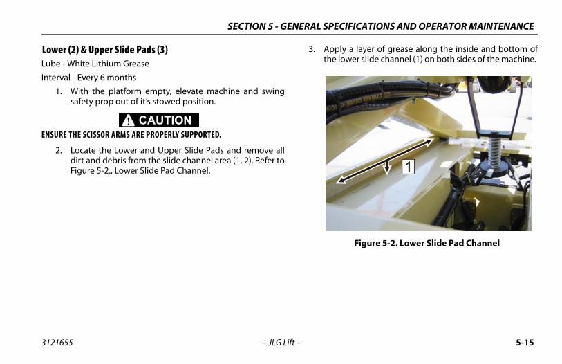
CIFICATIONS AND OPERATOR MAINTENANCE
5-15
ly a layer of grease along the inside and bottom oflower slide channel (1) on both sides of the machine.
Figure 5-2. Lower Slide Pad Channel
SECTION 5 - GENERAL SPE
3121655 – JLG Lift –
Lower (2) & Upper Slide Pads (3)Lube - White Lithium Grease
Interval - Every 6 months
1. With the platform empty, elevate machine and swingsafety prop out of it’s stowed position.
ENSURE THE SCISSOR ARMS ARE PROPERLY SUPPORTED.
2. Locate the Lower and Upper Slide Pads and remove alldirt and debris from the slide channel area (1, 2). Refer toFigure 5-2., Lower Slide Pad Channel.
3. Appthe

SECTION 5 - GENERAL SPECIFICATIONS AND OPERATOR MAINTENANCE
5-1 3121655
ended lubricating intervals are based one operations under normal conditions. Fores used in multi-shift operations and/or exposedile environments or conditions, lubrication fre-s must be increased accordingly.
6 – JLG Lift –
4. Apply a layer of grease along the inside and top of theupper slide channel (2) on both sides of the machine.Refer to Figure 5-3., Upper Slide Pad Channel.
NOTE: Recommmachinmachinto hostquencie
Figure 5-3. Upper Slide Pad Channel

CIFICATIONS AND OPERATOR MAINTENANCE
5-17
he lug nuts to the proper torque to prevent wheelsing loose. Use a torque wrench to tighten the fas-
you do not have a torque wrench, tighten the fasten-a lug wrench, then immediately have a service
r dealer tighten the lug nuts to the proper torque.tening will result in breaking the studs or perma-forming the mounting stud holes in the wheels. Theocedure for attaching wheels is as follows: t all nuts by hand to prevent cross threading. DO use a lubricant on threads or nuts.ten nuts in the following sequence.
tightening of the nuts should be done in stages. Fol-ing the recommended sequence, tighten nuts perel torque.
SECTION 5 - GENERAL SPE
3121655 – JLG Lift –
5.4 TIRES AND WHEELS
Tire Wear and Damage
Inspect tires periodically for wear or damage. Tires with wornedges or distorted profiles require replacement. Tires with sig-nificant damage in the tread area or side wall, require immedi-ate evaluation before placing the machine into service.
Wheel and Tire Replacement
Replacement wheels must have the same diameter and pro-file as the original. Replacement tires must be the same sizeand rating as the tire being replaced.
Wheel Installation
It is extremely important to apply and maintain proper wheelmounting torque.
WHEEL NUTS MUST BE INSTALLED AND MAINTAINED AT THE PROPERTORQUE TO PREVENT LOOSE WHEELS, BROKEN STUDS, AND POSSIBLE SEPA-RATION OF WHEEL FROM THE AXLE. BE SURE TO USE ONLY THE NUTSMATCHED TO THE CONE ANGLE OF THE WHEEL.
Tighten tfrom comteners. If ers with garage oOver-tighnently deproper pr
1. StarNOT
2. Tigh
3. Thelowwhe
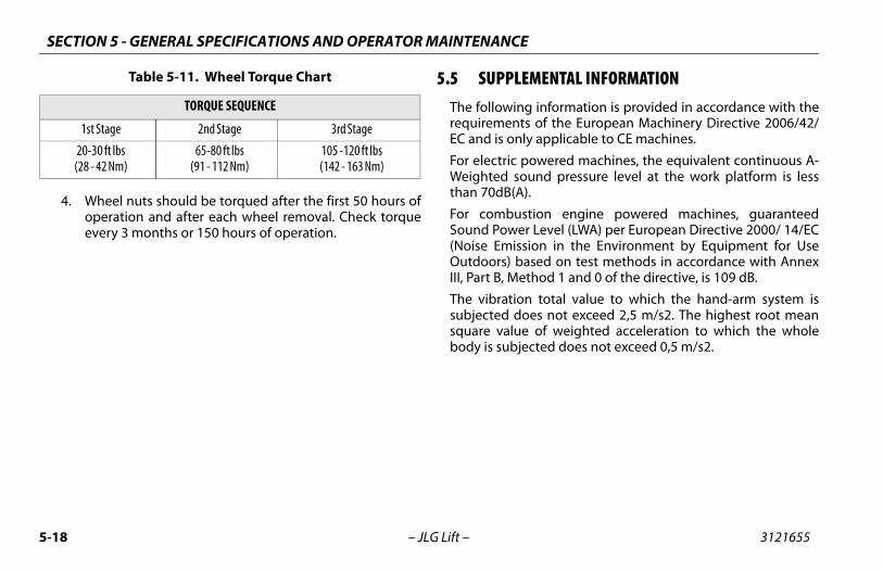
SECTION 5 - GENERAL SPECIFICATIONS AND OPERATOR MAINTENANCE
5-1 3121655
MENTAL INFORMATION information is provided in accordance with the of the European Machinery Directive 2006/42/ applicable to CE machines.
owered machines, the equivalent continuous A-nd pressure level at the work platform is less
ion engine powered machines, guaranteed Level (LWA) per European Directive 2000/ 14/ECon in the Environment by Equipment for Usesed on test methods in accordance with Annexhod 1 and 0 of the directive, is 109 dB.
total value to which the hand-arm system ises not exceed 2,5 m/s2. The highest root mean of weighted acceleration to which the wholected does not exceed 0,5 m/s2.
8 – JLG Lift –
4. Wheel nuts should be torqued after the first 50 hours ofoperation and after each wheel removal. Check torqueevery 3 months or 150 hours of operation.
5.5 SUPPLEThe followingrequirementsEC and is only
For electric pWeighted southan 70dB(A).
For combustSound Power(Noise EmissiOutdoors) baIII, Part B, Met
The vibrationsubjected dosquare valuebody is subje
Table 5-11. Wheel Torque Chart
TORQUE SEQUENCE
1st Stage 2nd Stage 3rd Stage
20-30 ft lbs(28 - 42 Nm)
65-80 ft lbs(91 - 112 Nm)
105 -120 ft lbs(142 - 163 Nm)

CIFICATIONS AND OPERATOR MAINTENANCE
5-19
S- Sheet 1
SECTION 5 - GENERAL SPE
3121655 – JLG Lift –
5.6 DECAL INSTALLATIONS
Figure 5-4. Decal Location - 1930E

SECTION 5 - GENERAL SPECIFICATIONS AND OPERATOR MAINTENANCE
5-2 3121655
heet 2
0 – JLG Lift –
Figure 5-5. Decal Location - 1930ES - S

CIFICATIONS AND OPERATOR MAINTENANCE
5-21
632ES - Sheet 1
SECTION 5 - GENERAL SPE
3121655 – JLG Lift –
Figure 5-6. Decal Location - 2032ES & 2

SECTION 5 - GENERAL SPECIFICATIONS AND OPERATOR MAINTENANCE
5-2 3121655
S - Sheet 2
2 – JLG Lift –
Figure 5-7. Decal Location - 2032ES & 2632E

CIFICATIONS AND OPERATOR MAINTENANCE
5-23
246ES - Sheet 1
SECTION 5 - GENERAL SPE
3121655 – JLG Lift –
Figure 5-8. Decal Location - 2646ES & 3

SECTION 5 - GENERAL SPECIFICATIONS AND OPERATOR MAINTENANCE
5-2 3121655
S - Sheet 2
4 – JLG Lift –
Figure 5-9. Decal Location - 2646ES & 3246E

CIFICATIONS AND OPERATOR MAINTENANCE
5-25
gend
Portuguese/Spanish
001181273-A
English/Chinese1001181274-A
Korean1001181275-A
Japan1001181269-A
N/A N/A N/A N/A
1700584 1700584 1700584 N/A
N/A N/A N/A N/A
3251813 3251813 3251813 3251813
N/A N/A N/A N/A
1704412 1704412 1704412 1704412
1705693 1705693 1705693 1705693
1703817 1704016 1704016 1704016
1702155 1702155 1702155 1702155
1701509 1701509 1701509 1701509
1703811 1703811 1703811 1703811
1703814 1703814 1703814 1703814
1704277 1704277 1704277 1704277
1703819 1703819 1703819 1703819
1703822 1703822 1703822 1703822
1705692 1705692 1705692 1705692
SECTION 5 - GENERAL SPE
3121655 – JLG Lift –
Table 5-12. Decal Location Le
Item ANSI1001181268-A
CE1001181269-A
Australian1001181270-A
English/French1001181271-A
English/Spanish1001181272-A 1
1 - 3 N/A N/A N/A N/A N/A
4 1001131270 N/A N/A 1700584 1700584
5 N/A N/A N/A N/A N/A
6 3251813 3251813 3251813 3251813 3251813
7-8 N/A N/A N/A N/A N/A
9 1704412 1704412 1704412 1704412 1704412
10 1705693 1705693 1705693 1705693 1705693
11 1704016 1704016 1704016 1704016 1703817
12 1702155 1702155 1702155 1702155 1702155
13 1701509 1701509 1701509 1701509 1701509
14 1703811 1703811 1703811 1703811 1703811
15 1703814 1703814 1703814 1703814 1703814
16 1704277 1704277 1704277 1704277 1704277
17 1703819 1703819 1703819 1703819 1703819
18 1703822 1703822 1703822 1703822 1703822
19 1705692 1705692 1705692 1705692 1705692

SECTION 5 - GENERAL SPECIFICATIONS AND OPERATOR MAINTENANCE
5-2 3121655
/A N/A N/A N/A
5722 1705694 1705694 1705673
3834 1705695 1705695 1705671
5726 1705946 1706057 N/A
5894 1705680 1705680 N/A
5727 1705679 1705679 N/A
5721 1705681 1705681 N/A
4341 1704344 1707022 1705670
/A N/A N/A N/A
(19(20(26(26(32
d
Itguese/
anish81273-A
English/Chinese1001181274-A
Korean1001181275-A
Japan1001181269-A
6 – JLG Lift –
20 N/A N/A N/A N/A N/A N
21 1705694 1705673 1705673 1705694 1705694 170
22 1705695 1705671 1705671 1705695 1705695 170
23 1705686 N/A N/A 1705723 1705720 170
24 1705680 N/A N/A 1705680 1705680 170
25 1705679 N/A N/A 1705679 1705679 170
26 1705681 N/A N/A 1705681 1705681 170
27 1703813 1705670 1705670 1704340 1704339 170
28 N/A N/A N/A N/A N/A N
2930ES)32ES)32ES)46ES)46ES)
10010999191001178302100117830410010999221001099923
Table 5-12. Decal Location Legen
em ANSI1001181268-A
CE1001181269-A
Australian1001181270-A
English/French1001181271-A
English/Spanish1001181272-A
PortuSp
10011
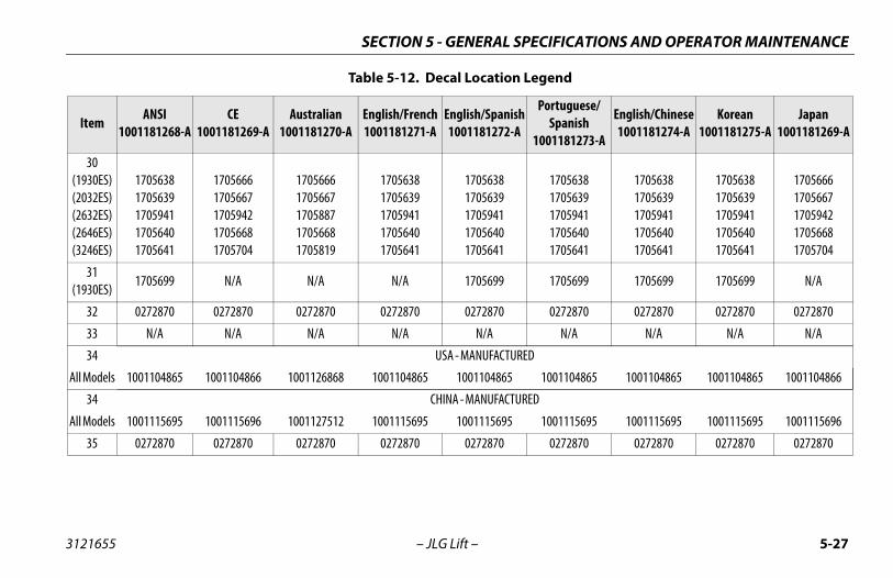
CIFICATIONS AND OPERATOR MAINTENANCE
5-27
17056381705639170594117056401705641
17056381705639170594117056401705641
17056381705639170594117056401705641
17056661705667170594217056681705704
1705699 1705699 1705699 N/A
0272870 0272870 0272870 0272870
N/A N/A N/A N/A
1001104865 1001104865 1001104865 1001104866
1001115695 1001115695 1001115695 1001115696
0272870 0272870 0272870 0272870
gend
Portuguese/Spanish
001181273-A
English/Chinese1001181274-A
Korean1001181275-A
Japan1001181269-A
SECTION 5 - GENERAL SPE
3121655 – JLG Lift –
30(1930ES)(2032ES)(2632ES)(2646ES)(3246ES)
17056381705639170594117056401705641
17056661705667170594217056681705704
17056661705667170588717056681705819
17056381705639170594117056401705641
17056381705639170594117056401705641
31(1930ES)
1705699 N/A N/A N/A 1705699
32 0272870 0272870 0272870 0272870 0272870
33 N/A N/A N/A N/A N/A
34 USA - MANUFACTURED
All Models 1001104865 1001104866 1001126868 1001104865 1001104865
34 CHINA - MANUFACTURED
All Models 1001115695 1001115696 1001127512 1001115695 1001115695
35 0272870 0272870 0272870 0272870 0272870
Table 5-12. Decal Location Le
Item ANSI1001181268-A
CE1001181269-A
Australian1001181270-A
English/French1001181271-A
English/Spanish1001181272-A 1

SECTION 5 - GENERAL SPECIFICATIONS AND OPERATOR MAINTENANCE
5-2 3121655
(19(20(26(26(32
56474134631063116311
17056471704134170631017063111706311
17056471704134170631017063111706311
17056481706310170631017063121706312
/A N/A N/A N/A
5303 N/A N/A N/A
/A N/A 3251243 N/A
5725 1705943 1706052 N/A
5724 1705944 1706056 N/A
/A N/A N/A N/A
5719 1705945 1706053 N/A
1499 1701499 1701499 1701499
(19 120623 1001120622 1001120621 1001092497
094359 1001094359 1001094359 1001094359
146794 1001146794 1001146794 1001146795
d
Itguese/
anish81273-A
English/Chinese1001181274-A
Korean1001181275-A
Japan1001181269-A
8 – JLG Lift –
3630ES)32ES)32ES)46ES)46ES)
17056471704134170631017063111706311
17056481706310170631017063121706312
17056481706310170631017063121706312
17056471704134170631017063111706311
17056471704134170631017063111706311
170170170170170
37 N/A N/A N/A N/A N/A N
38 N/A N/A N/A 1705303 N/A 170
39 N/A N/A N/A N/A N/A N
40 N/A N/A N/A 1705717 1705725 170
41 N/A N/A N/A 1705718 1705724 170
42 N/A N/A N/A N/A N/A N
43 N/A N/A N/A 3252098 1705719 170
44 1701499 1701499 1701499 1701499 1701499 170
4530ES) 1001092071 1001092497 1001092497 1001092580 1001120629 1001
46 1001094359 1001094359 1001094359 1001094359 1001094359 1001
47 1001146794 1001146795 1001146795 1001146794 1001146794 1001
Table 5-12. Decal Location Legen
em ANSI1001181268-A
CE1001181269-A
Australian1001181270-A
English/French1001181271-A
English/Spanish1001181272-A
PortuSp
10011

CIFICATIONS AND OPERATOR MAINTENANCE
5-29
from the Multifunction Digital Indicator (MDI). Forons of any limit switches/sensors, refer to Section 2.ess lamp flash code. To troubleshoot multiple DTCs,uring a check, conclude the check by cycling the
SECTION 5 - GENERAL SPE
3121655 – JLG Lift –
5.7 DIAGNOSTIC TROUBLE CODES (DTC)
IntroductionThis sub-section provides a reference for Diagnostic Trouble Codes (DTC) readmore information on the MDI, refer to Section 3. For information on the locatiDTCs are sorted in groups by the first two digits, which is also the system distrstart with the DTC with the higher first two digits. If a correction is made dmachine power, using the emergency stop switch.

SECTION 5 - GENERAL SPECIFICATIONS AND OPERATOR MAINTENANCE
5-3 3121655
5.8
DT CHECK
connector.nostic connector.a qualified JLG mechanic.
0
0
0 machine is tilted. If so, lower the platform and reposition a level surface.
platform. is part of the ground control box. Check that the groundecured to the machine. pothole protection switches are securely mounted. elevation angle sensor is securely mounted.a qualified JLG mechanic.
0 – JLG Lift –
DIAGNOSTIC TROUBLE CODES (DTC) CHECK TABLES
0-0 Help Comments
C FAULT MESSAGE DESCRIPTION
Error (Displayed on MDI) The MDI is powered, but cannot communi-cate with the control system.
• Check the MDI• Check the diag
Refer problem to
01 EVERYTHING OK The normal help message in platform mode. Displays on the analyzer only.
02 GROUND MODE OK The normal help message in ground mode. Displays on the analyzer only.
03 ALARM SOUNDING - TILTED & ABOVE ELEVATION
Control system senses that the platform is elevated and the vehicle is tilted, and the machine not configured to cutout.
• Check that thethe machine to
• Fully stow the• The tilt sensor
control box is s• Check that the• Check that the
Refer problem to

CIFICATIONS AND OPERATOR MAINTENANCE
5-31
w the platform.at the elevation angle sensor is securely mounted.at the pothole protection switches are securely mounted.m to a qualified JLG mechanic.
at the machine is tilted. If so, lower the platform and repositionhine to a level surface.w the platform.sensor is part of the ground control box. Check that the groundox is secured to the machine.at the pothole protection switches are securely mounted.at the elevation angle sensor is securely mounted.m to a qualified JLG mechanic.
at the zone is set appropriately for the platform load.at the platform height is at the rated maximum height specifica- for 2632 or 26’ for the 3246).at the elevation angle sensor is securely mounted.are any elevation sensor faults (DTC 251, 252, 2511, or 2512),hoot those first.m to a qualified JLG mechanic.
CHECK
SECTION 5 - GENERAL SPE
3121655 – JLG Lift –
004 DRIVING AT CUTBACK - ABOVE ELEVA-TION
The platform is elevated and the machine is driving.
• Fully sto• Check th• Check th
Refer proble
005 DRIVE & LIFT UP PREVENTED - TILTED & ELEVATED
Driving is not possible since the platform is elevated and the chassis is not level.
• Check ththe mac
• Fully sto• The tilt
control b• Check th• Check th
Refer proble
006 LIFT UP PREVENTED - MAX HEIGHT ZONE A
The vehicle has reached the maximum height and further lift up motion is not possible. Applicable to 2632ES or 3246ES.
• Check th• Check th
tion (20’• Check th• If there
troublesRefer proble
0-0 Help Comments
DTC FAULT MESSAGE DESCRIPTION

SECTION 5 - GENERAL SPECIFICATIONS AND OPERATOR MAINTENANCE
5-3 3121655
0 ructions around the pot-hole protection mechanisms. PHP switches are securely mounted.a qualified JLG mechanic.
0 ion should resume after power is cycled off then back on.s charge, condition, etc.a qualified JLG mechanic.
0 elevation angle sensor is securely mounted.a qualified JLG mechanic.
DT CHECK
DT CHECK
2 . No check necessary.
2 a qualified JLG mechanic.
2 – JLG Lift –
07 DRIVING AT CUTBACK - POTHOLE STILL ENGAGED
While stowed, drive speed is reduced since the control system detected that the pot-hole protection mechanism failed to retract.
• Check for obst• Check that the
Refer problem to
08 FUNCTIONS LOCKED OUT - SYSTEM POWERED DOWN
After 2 hours without activity, the control system enters a low-power state to pre-serve battery charge.
• Normal operat• Check batterie
Refer problem to
09 DRIVE PREVENTED - ELEVATED ABOVE DRIVE CUTOUT HEIGHT
The platform is elevated above the cali-brated cutout height.
• Check that theRefer problem to
0-0 Help Comments
C FAULT MESSAGE DESCRIPTION
2-1 Power-Up
C FAULT MESSAGE DESCRIPTION
11 POWER CYCLE This help message is issued at each power cycle. Displays on the analyzer only.
Normal operation
12 KEYSWITCH FAULTY Both platform and ground modes are selected simultaneously. Defaults to ground mode.
Refer problem to

CIFICATIONS AND OPERATOR MAINTENANCE
5-33
CHECK
the horn switch is damaged, obstructed or jammed.m to a qualified JLG mechanic.
the indoor/outdoor (zone A / zone B) capacity switch is damaged,ed or jammed.m to a qualified JLG mechanic.
ive/lift switch for visible damage.m to a qualified JLG mechanic.
the steer left switch is obstructed or jammed.m to a qualified JLG mechanic.
the steer right switch is obstructed or jammed.m to a qualified JLG mechanic.
ystick and check to see if a power cycle will clear DTC.m to a qualified JLG mechanic.
the steer switches are damaged, obstructed or jammed.m to a qualified JLG mechanic.
joystick and allow to center.the joystick is obstructed or jammed.m to a qualified JLG mechanic.
the trigger switch is obstructed or jammed.m to a qualified JLG mechanic.
SECTION 5 - GENERAL SPE
3121655 – JLG Lift –
2-2 Platform Controls
DTC FAULT MESSAGE DESCRIPTION
221 FUNCTION PROBLEM - HORN PERMA-NENTLY SELECTED
The horn switch was closed during power-up in platform mode.
• Check if Refer proble
222 FUNCTION PROBLEM - INDOOR / OUT-DOOR PERMANENTLY SELECTED
The indoor / outdoor (zone A / zone B) switch was closed during power-up in plat-form mode.
• Check if obstruct
Refer proble
223 FUNCTION PROBLEM - DRIVE & LIFT ACTIVE TOGETHER
The drive and lift inputs are closed simulta-neously in platform mode.
• Check drRefer proble
224 FUNCTION PROBLEM - STEER LEFT PERMANENTLY SELECTED
The steer left switch was closed during power-up in platform mode.
• Check if Refer proble
225 FUNCTION PROBLEM - STEER RIGHT PERMANENTLY SELECTED
The steer right switch was closed during power-up in platform mode.
• Check if Refer proble
226 ACCELERATOR FAULTY - WIPER OUT OF RANGE
There is a problem with the joystick. • Center joRefer proble
227 STEER SWITCHES FAULTY The steer left and steer right inputs were closed simultaneously.
• Check if Refer proble
228 FUNCTION LOCKED OUT - ACCELERA-TOR NOT CENTERED
The joystick was not centered at power-up. • Release • Check if
Refer proble
229 FUNCTION PROBLEM - TRIGGER PER-MANENTLY CLOSED
The trigger switch was closed during power-up in platform mode.
• Check if Refer proble

SECTION 5 - GENERAL SPECIFICATIONS AND OPERATOR MAINTENANCE
5-3 3121655
22 gger switch is obstructed or jammed.a qualified JLG mechanic.
22 function is active, if Yes; to a qualified JLG mechanic.
DT CHECK
DT CHECK
2 t switch is obstructed or jammed.a qualified JLG mechanic.
2 t switch is obstructed or jammed.a qualified JLG mechanic.
2 ake release switch is obstructed or jammed.a qualified JLG mechanic.
4 – JLG Lift –
10 TRIGGER CLOSED TOO LONG WHILE IN NEUTRAL
The trigger switch was closed for more than five seconds while the joystick was centered.
• Check if the triRefer problem to
32 FUNCTION PROBLEM - DRIVE & LIFT BOTH OPEN
The drive and lift inputs are both de-ener-gized in platform mode.
• Check if eitherRefer problem
2-2 Platform Controls
C FAULT MESSAGE DESCRIPTION
2-3 Ground Controls
C FAULT MESSAGE DESCRIPTION
31 FUNCTION PROBLEM - LIFT PERMA-NENTLY SELECTED
The ground control box lift switch was closed up or down, during power-up in ground mode.
• Check if the lifRefer problem to
32 GROUND LIFT UP / DOWN ACTIVE TOGETHER
The lift up / down inputs are closed simul-taneously.
• Check if the lifRefer problem to
33 FUNCTION PROBLEM - BRAKE RELEASE PERMANENTLY SELECTED
The manual brake release switch was closed during power-up.
• Check if the brRefer problem to

CIFICATIONS AND OPERATOR MAINTENANCE
5-35
CHECK
hat the platform elevation sensor is securely mounted andged.m to a qualified JLG mechanic.
m to a qualified JLG mechanic.
the charger is connected to off board power source and discon-esired.m to a qualified JLG mechanic.
the charger is connected to off board power source and discon-esired.m to a qualified JLG mechanic.
excess weight from the platform.at the platform is not caught on something, preventing up or
ovement.m to a qualified JLG mechanic.
r obstructions or mechanical problems around the pot-hole pro-echanisms.
at the PHP switches are securely mounted.m to a qualified JLG mechanic.
SECTION 5 - GENERAL SPE
3121655 – JLG Lift –
2-5 Function Prevented
DTC FAULT MESSAGE DESCRIPTION
251 ELEV ANGLE SENSOR FAULTY - VOLT-AGE OUT OF RANGE
There is a problem with the elevation angle sensor input.
• Check tundama
Refer proble
252 ELEV ANGLE SENSOR HAS NOT BEEN CALIBRATED
The elevation angle sensor has not been calibrated.
Refer proble
253 DRIVE PREVENTED - CHARGER CON-NECTED
Driving is not possible while the vehicle is charging.
• Check if nect if d
Refer proble
254 DRIVE & LIFT UP PREVENTED - CHAR-GER CONNECTED
Drive or lift is not possible while the vehicle is charging AND is configured to prevent all motion.
• Check if nect if d
Refer proble
255 PLATFORM OVERLOADED The load sensing system measured plat-form load is excessive.
• Remove• Check th
down mRefer proble
256 DRIVE PREVENTED - POTHOLE NOT ENGAGED
Driving is not possible while elevated since the pot-hole protection system failed to deploy.
• Check fotection m
• Check thRefer proble

SECTION 5 - GENERAL SPECIFICATIONS AND OPERATOR MAINTENANCE
5-3 3121655
2 a qualified JLG mechanic.
2 brake release switch again or cycle power to clear manualode.
ake release switch is obstructed or jammed.a qualified JLG mechanic.
2 a qualified JLG mechanic.
25 is not stuck on something preventing movement.a qualified JLG mechanic.
25 elevation angle sensor is securely mounted.a qualified JLG mechanic.
25 elevation angle sensor is securely mounted.a qualified JLG mechanic.
DT CHECK
6 – JLG Lift –
57 ELEV PROX PERMANENTLY CLOSED - CHECK PROX AND ANGLE ADJUST-MENT
The elevation proximity switch shows the platform to be stowed, while the elevation angle sensor shows the platform to be raised. The elevation proximity switch is only found on certain older lifts. This switch is not used on current machines so this DTC should not occur.
Refer problem to
58 DRIVE & LIFT PREVENTED - BRAKES ELECTRICALLY RELEASED FOR TOWING
Manual brake release mode is activated with the switch in the battery box near the ground control box. Drive or lift is not pos-sible.
• Push manual brake release m
• Check if the brRefer problem to
59 MODEL CHANGED - HYDRAULICS SUS-PENDED - CYCLE EMS
The model selection has been changed. Refer problem to
10 DRIVE PREVENTED - BRAKES NOT RELEASING
There is a problem with the drive or brake system.
• Ensure vehicleRefer problem to
11 ELEV ANGLE SENSOR FAULTY - NOT MOUNTED
The input voltage from the elevation angle sensor indicates the elevation angle sensor is not mounted.
• Check that theRefer problem to
12 ELEV ANGLE SENSOR NOT DETECTING CHANGE
The input voltage from the elevation angle sensor did not change while vehicle was lifting up.
• Check that theRefer problem to
2-5 Function Prevented
C FAULT MESSAGE DESCRIPTION

CIFICATIONS AND OPERATOR MAINTENANCE
5-37
CHECK
m to a qualified JLG mechanic.
m to a qualified JLG mechanic.
CHECK
m to a qualified JLG mechanic.
m to a qualified JLG mechanic.
m to a qualified JLG mechanic.
CHECK
m to a qualified JLG mechanic.
SECTION 5 - GENERAL SPE
3121655 – JLG Lift –
3-1 Line Contactor Open Circuit
DTC FAULT MESSAGE DESCRIPTION
311 OPEN CIRCUIT LINE CONTACTOR There is a problem with the line contactor. Refer proble
312 CONTACTOR DRIVER PERMANENTLY OFF
There is a problem with the power module line contactor control.
Refer proble
3-2 Line Contactor Short Circuit
DTC FAULT MESSAGE DESCRIPTION
321 LINE CONTACTOR MISWIRED ON OR WELDED
There is a problem with the line contactor. Refer proble
322 CONTACTOR DRIVER PERMANENTLY ON
There is a problem with the power module line contactor control.
Refer proble
326 AUXILIARY RELAY - SHORT TO BAT-TERY
There is a problem with the auxiliary relay contacts or wiring.
Refer proble
3-3 Ground Output Driver
DTC FAULT MESSAGE DESCRIPTION
331 BRAKE SHORT TO BATTERY A problem has been detected in this func-tion.
Refer proble

SECTION 5 - GENERAL SPECIFICATIONS AND OPERATOR MAINTENANCE
5-3 3121655
3 a qualified JLG mechanic.
3 a qualified JLG mechanic.
3 a qualified JLG mechanic.
3 a qualified JLG mechanic.
3 a qualified JLG mechanic.
3 a qualified JLG mechanic.
3 a qualified JLG mechanic.
3 a qualified JLG mechanic.
33 a qualified JLG mechanic.
33 a qualified JLG mechanic.
DT CHECK
8 – JLG Lift –
32 BRAKE OPEN CIRCUIT A problem has been detected in this func-tion.
Refer problem to
33 LIFT UP SHORT TO BATTERY A problem has been detected in this func-tion.
Refer problem to
34 LIFT UP OPEN CIRCUIT A problem has been detected in this func-tion.
Refer problem to
35 LIFT DN SHORT TO BATTERY A problem has been detected in this func-tion.
Refer problem to
36 LIFT DN OPEN CIRCUIT A problem has been detected in this func-tion.
Refer problem to
37 STEER LEFT SHORT TO BATTERY A problem has been detected in this func-tion.
Refer problem to
38 STEER LEFT OPEN CIRCUIT A problem has been detected in this func-tion.
Refer problem to
39 STEER RIGHT SHORT TO BATTERY A problem has been detected in this func-tion.
Refer problem to
10 STEER RIGHT OPEN CIRCUIT A problem has been detected in this func-tion.
Refer problem to
11 GROUND ALARM SHORT TO BATTERY A problem has been detected in this func-tion.
Refer problem to
3-3 Ground Output Driver
C FAULT MESSAGE DESCRIPTION

CIFICATIONS AND OPERATOR MAINTENANCE
5-39
m to a qualified JLG mechanic.
m to a qualified JLG mechanic.
m to a qualified JLG mechanic.
m to a qualified JLG mechanic.
m to a qualified JLG mechanic.
m to a qualified JLG mechanic.
m to a qualified JLG mechanic.
m to a qualified JLG mechanic.
m to a qualified JLG mechanic.
m to a qualified JLG mechanic.
CHECK
SECTION 5 - GENERAL SPE
3121655 – JLG Lift –
3312 LEFT BRAKE SHORT TO BATTERY A problem has been detected in this func-tion.
Refer proble
3313 RIGHT BRAKE SHORT TO BATTERY A problem has been detected in this func-tion.
Refer proble
3314 LEFT BRAKE OPEN CIRCUIT A problem has been detected in this func-tion.
Refer proble
3315 RIGHT BRAKE OPEN CIRCUIT A problem has been detected in this func-tion.
Refer proble
33297 LEFT BRAKE - SHORT TO GROUND A problem has been detected in this func-tion.
Refer proble
33298 STEER LEFT VALVE - SHORT TO GROUND
A problem has been detected in this func-tion.
Refer proble
33299 LINE CONTACTOR COIL - SHORT TO BATTERY
A problem has been detected in this func-tion.
Refer proble
33302 NEGATIVE SUPPLY - SHORT TO BAT-TERY
A problem has been detected in this func-tion.
Refer proble
33303 NEGATIVE SUPPLY - SHORT TO GROUND
A problem has been detected in this func-tion.
Refer proble
33304 RIGHT BRAKE - SHORT TO GROUND A problem has been detected in this func-tion.
Refer proble
3-3 Ground Output Driver
DTC FAULT MESSAGE DESCRIPTION

SECTION 5 - GENERAL SPECIFICATIONS AND OPERATOR MAINTENANCE
5-4 3121655
33 a qualified JLG mechanic.
33 a qualified JLG mechanic.
33 a qualified JLG mechanic.
DT CHECK
DT CHECK
4 nd allow to cool. in ambients over 140° F (60° C).
a qualified JLG mechanic.
4 a qualified JLG mechanic.
4 a qualified JLG mechanic.
0 – JLG Lift –
305 STEER RIGHT VALVE - SHORT TO GROUND
A problem has been detected in this func-tion.
Refer problem to
406 LIFT UP VALVE - SHORT TO GROUND A problem has been detected in this func-tion.
Refer problem to
407 LIFT DN VALVE - SHORT TO GROUND A problem has been detected in this func-tion.
Refer problem to
3-3 Ground Output Driver
C FAULT MESSAGE DESCRIPTION
4-2 Thermal Limit (SOA)
C FAULT MESSAGE DESCRIPTION
21 POWER MODULE TOO HOT - PLEASE WAIT
The power module has reached thermal cutout.
• Power down a• Do not operate
Refer problem to
22 DRIVING AT CUTBACK - POWER MOD-ULE CURRENT LIMIT
The drive portion of the power module has reached thermal limit.
Refer problem to
23 LIFT UP AT CUTBACK - POWER MOD-ULE CURRENT LIMIT
The lift up portion of the power module has reached thermal limit.
Refer problem to

CIFICATIONS AND OPERATOR MAINTENANCE
5-41
CHECK
e batteries or check for damaged batteries.ttery charger function.m to a qualified JLG mechanic.
due to improper battery charging or incorrect voltage batteriesed.m to a qualified JLG mechanic.
due to improper battery charging or incorrect voltage batteriesed.m to a qualified JLG mechanic.
e batteries or check for damaged batteries.m to a qualified JLG mechanic.
r severely discharged battery, loose cables or for damaged bat-erwise;blem to a qualified JLG mechanic.
CHECK
m to a qualified JLG mechanic.
SECTION 5 - GENERAL SPE
3121655 – JLG Lift –
4-4 Battery Supply
DTC FAULT MESSAGE DESCRIPTION
441 BATTERY VOLTAGE TOO LOW - SYSTEM SHUTDOWN
A problem has been detected with the bat-teries or power module.
• Recharg• Check ba
Refer proble
442 BATTERY VOLTAGE TOO HIGH - SYSTEM SHUTDOWN
A problem has been detected with the bat-teries or power module.
• May be being us
Refer proble
443 LSS BATTERY VOLTAGE TOO HIGH A problem has been detected with the load sense system.
• May be being us
Refer proble
444 LSS BATTERY VOLTAGE TOO LOW A problem has been detected with the load sense system.
• RechargRefer proble
44644214422
LOGIC SUPPLY VOLTAGE OUT OF RANGE The System Module logic supply voltage was measured to be out of normal operat-ing range.
• Check fotery; oth
• Refer pro
6-6 Communication
DTC FAULT MESSAGE DESCRIPTION
661 CANBUS FAILURE - POWER MODULE The control system failed to receive mes-sages from the power module.
Refer proble
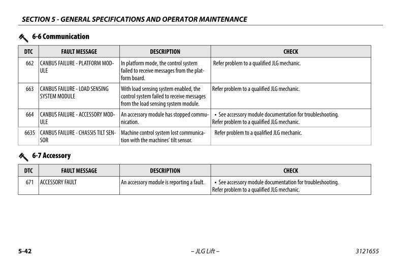
SECTION 5 - GENERAL SPECIFICATIONS AND OPERATOR MAINTENANCE
5-4 3121655
6 a qualified JLG mechanic.
6 a qualified JLG mechanic.
6 module documentation for troubleshooting.a qualified JLG mechanic.
66 a qualified JLG mechanic.
DT CHECK
DT CHECK
6 module documentation for troubleshooting.a qualified JLG mechanic.
2 – JLG Lift –
62 CANBUS FAILURE - PLATFORM MOD-ULE
In platform mode, the control system failed to receive messages from the plat-form board.
Refer problem to
63 CANBUS FAILURE - LOAD SENSING SYSTEM MODULE
With load sensing system enabled, the control system failed to receive messages from the load sensing system module.
Refer problem to
64 CANBUS FAILURE - ACCESSORY MOD-ULE
An accessory module has stopped commu-nication.
• See accessory Refer problem to
35 CANBUS FAILURE - CHASSIS TILT SEN-SOR
Machine control system lost communica-tion with the machines’ tilt sensor.
Refer problem to
6-6 Communication
C FAULT MESSAGE DESCRIPTION
6-7 Accessory
C FAULT MESSAGE DESCRIPTION
71 ACCESSORY FAULT An accessory module is reporting a fault. • See accessory Refer problem to

CIFICATIONS AND OPERATOR MAINTENANCE
5-43
CHECK
m to a qualified JLG mechanic.
m to a qualified JLG mechanic.
m to a qualified JLG mechanic.
m to a qualified JLG mechanic.
m to a qualified JLG mechanic.
m to a qualified JLG mechanic.
m to a qualified JLG mechanic.
m to a qualified JLG mechanic.
m to a qualified JLG mechanic.
SECTION 5 - GENERAL SPE
3121655 – JLG Lift –
7-7 Electric Motor
DTC FAULT MESSAGE DESCRIPTION
771 OPEN CIRCUIT DRIVE MOTOR WIRING The power module detected a problem in the drive motors' power circuit wiring.
Refer proble
772 STALLED TRACTION MOTOR OR POWER WIRING ERROR
The power module detected a problem in the drive motors' power circuit wiring.
Refer proble
773 CAPACITOR BANK FAULT - CHECK POWER CIRCUITS
The power module detected a problem in the pump or drive motors' power circuit wiring.
Refer proble
774 SHORT CIRCUIT FIELD WIRING The power module detected a problem in the drive motors' power circuit wiring.
Refer proble
775 OPEN CIRCUIT FIELD WIRING The power module detected a problem in the drive motors' power circuit wiring.
Refer proble
776 STALLED PUMP MOTOR OR POWER WIRING ERROR
The power module detected a problem in the drive motors' power circuit wiring.
Refer proble
777 OPEN CIRCUIT PUMP MOTOR WIRING The power module detected a problem in the drive motors' power circuit wiring.
Refer proble
778 TRACTION T HIGH - CHECK POWER CIR-CUITS
The power module detected a problem in the drive motors' power circuit wiring.
Refer proble
779 TRACTION T LOW - CHECK POWER CIR-CUITS
The power module detected a problem in the drive motors' power circuit wiring.
Refer proble

SECTION 5 - GENERAL SPECIFICATIONS AND OPERATOR MAINTENANCE
5-4 3121655
77 a qualified JLG mechanic.
77 a qualified JLG mechanic.
77 d by transporting an excessive load on a steep grade.
77 /off, if problem persists;a qualified JLG mechanic.
DT CHECK
DT CHECK
8 a qualified JLG mechanic.
8 a qualified JLG mechanic.
4 – JLG Lift –
10 PUMP P HIGH - CHECK POWER CIR-CUITS
The power module detected a problem in the drive motors' power circuit wiring.
Refer problem to
11 PUMP P LOW - CHECK POWER CIR-CUITS
The power module detected a problem in the drive motors' power circuit wiring.
Refer problem to
41 ARMATURE BRAKING CURRENT TOO HIGH
The power module has detected excessive braking current .
This can be cause
42 FIELD VOLTAGE IMPROPER The power module detected a problem in the drive motors' power circuit wiring.
Recycle power onRefer problem to
7-7 Electric Motor
C FAULT MESSAGE DESCRIPTION
8-1 Tilt Sensor
C FAULT MESSAGE DESCRIPTION
11 TILT SENSOR NOT CALIBRATED The tilt sensor calibration has not been performed.
Refer problem to
12 NO DATA FROM TILT SENSOR - NOT CONNECTED OR FAULTY
No signal from tilt sensor. Refer problem to

CIFICATIONS AND OPERATOR MAINTENANCE
5-45
CHECK
m to a qualified JLG mechanic.
m to a qualified JLG mechanic.
m to a qualified JLG mechanic.
m to a qualified JLG mechanic.
m to a qualified JLG mechanic.
SECTION 5 - GENERAL SPE
3121655 – JLG Lift –
8-2 Platform Load Sense
DTC FAULT MESSAGE DESCRIPTION
821 LSS CELL #1 ERROR A problem has been detected with the load sense system.
Refer proble
822 LSS CELL #2 ERROR A problem has been detected with the load sense system.
Refer proble
823 LSS CELL #3 ERROR A problem has been detected with the load sense system.
Refer proble
824 LSS CELL #4 ERROR A problem has been detected with the load sense system.
Refer proble
825 LSS HAS NOT BEEN CALIBRATED The load sensing system module has not been calibrated
Refer proble

SECTION 5 - GENERAL SPECIFICATIONS AND OPERATOR MAINTENANCE
5-4 3121655
DT CHECK
9 a qualified JLG mechanic.
9 a qualified JLG mechanic.
9 a qualified JLG mechanic.
9 a qualified JLG mechanic.
9 a qualified JLG mechanic.
9 a qualified JLG mechanic.
9 a qualified JLG mechanic.
9 a qualified JLG mechanic.
9 a qualified JLG mechanic.
6 – JLG Lift –
9-9 Hardware
C FAULT MESSAGE DESCRIPTION
91 LSS WATCHDOG RESET A problem has been detected with the load sense system.
Refer problem to
92 LSS EEPROM ERROR A problem has been detected with the load sense system.
Refer problem to
93 LSS INTERNAL ERROR - PIN EXCITA-TION
A problem has been detected with the load sense system.
Refer problem to
94 LSS INTERNAL ERROR - DRDY MISSING FROM A/D
A problem has been detected with the load sense system.
Refer problem to
95 POWER MODULE FAILURE - PERSON-ALITY RANGE ERROR
A problem has been detected with the power module.
Refer problem to
96 POWER MODULE FAILURE - INTERNAL ERROR
A problem has been detected with the power module.
Refer problem to
97 POWER MODULE FAILURE - CHECK POWER CIRCUITS OR MOSFET SHORT CIRCUIT
A problem has been detected with the power module.
Refer problem to
98 EEPROM FAILURE - CHECK ALL SET-TINGS
A problem has been detected with the ground board.
Refer problem to
99 FUNCTION LOCKED OUT - POWER MODULE SOFTWARE VERSION IMPROPER
The power module software version is not compatible with the rest of the system.
Refer problem to

CIFICATIONS AND OPERATOR MAINTENANCE
5-47
m to a qualified JLG mechanic.
m to a qualified JLG mechanic.
m to a qualified JLG mechanic.
m to a qualified JLG mechanic.
CHECK
SECTION 5 - GENERAL SPE
3121655 – JLG Lift –
9910 FUNCTION LOCKED OUT - PLATFORM MODULE SOFTWARE VERSION IMPROPER
The platform board software version is not compatible with the rest of the system.
Refer proble
9911 FUNCTION LOCKED OUT - LSS MODULE SOFTWARE VERSION IMPROPER
The load sensing system module software version is not compatible with the rest of the system.
Refer proble
9912 POWER MODULE FAILURE - SYSTEM MONITOR
A problem has been detected with the power module.
Refer proble
9924 FUNCTIONS LOCKED OUT - MACHINE NOT CONFIGURED
A new ground board was installed but not configured.
Refer proble
9-9 Hardware
DTC FAULT MESSAGE DESCRIPTION

SECTION 5 - GENERAL SPECIFICATIONS AND OPERATOR MAINTENANCE
5-4 3121655
99999999999999999999999999999999
99999999999999
wer on /off a few times if this doesn’t clear the DTC, qualified JLG mechanic.
DT CHECK
8 – JLG Lift –
50515253545556575860626364697170
143144145146147148149
POWER MODULE FAILURE - INTERNAL ERROR
A problem has been detected with the power module.
Cycle machine porefer problem to a
9-9 Hardware
C FAULT MESSAGE DESCRIPTION

SECTION 6 - INSPECTION AND REPAIR LOG
6-1
REPAIR LOG
ir Log
ts
3121655 – JLG Lift –
SECTION 6. INSPECTION ANDMachine Serial Number____________________________________
Table 6-1. Inspection and Repa
Date Commen

SECTION 6 - INSPECTION AND REPAIR LOG
6-2 3121655
og
– JLG Lift –
Table 6-1. Inspection and Repair L
Date Comments

SECTION 7 - ACCESSORIES
7-1
IESels)
KET
E AUS Japan China
X X X
X X
X X X
X X X
X X X
X X X
X X X
X X
X X X
X X
X X X
X X X
X X X
X X X
X X X
3121655 – JLG Lift –
SECTION 7. ACCESSORTable 7-1. Accessories (All Mod
AccessoryMAR
ANSI (USA Only)
ANSI CSA C
1/2 Airline X X X X
Anti-Vandalism Cover X X
Electrician’s Tree X X X X
Electrician’s Package X X X X
Panel Carrier X X X X
Pipe Racks X X X X
Plant Package X X X
Platform Control Box Cover X X
Platform Control Box Hanger X X X X
Platform Rail Padding (w/ Limit Switch) X X X
Platform Rail Padding (no Limit Switch) X X X X
Plumber’s Package X X X X
QuikWelder X X X X
Platform Worklights X X X X
WorkStation X X X X

SECTION 7 - ACCESSORIES
7-2 3121655
e (All Models)
INCOMPATIBLE WITHINTERCHANGABLE
WITH (Note 2)
1/2 A QuikWelder
Anti- tform Box Cover, Platform Box Hanger
Elect & Plumber’s Packages, Platform Rail Pad-ng, Platform Worklights, QuikWelder
Elect l Carrier, Platform Rail Padding, Platform Worklights, QuikWelder, Pipe Racks are interchangeable with Panel Carrier
Inver
Pane form Rail Padding, Platform Worklights Pipe Racks
Pipe form Rail Padding, Platform Worklights Panel Carrier
Plant l Carrier, Platform Rail Padding, Platform Worklights, QuikWelder Pipe Racks are interchangeable with Panel Carrier
Platfo andalism Package, Platform Control Box Hanger
Platfo andalism Package, Platform Control Box Cover
– JLG Lift –
Table 7-2. Options/Accessories Relationship Tabl
ACCESSORY REQUIRED ITEMCOMPATIBLE WITH
(Notes 1 & 3)
irlineAnti-Vandalism Package, Electrician’s Tree, Elec-
trician’s/Plant/Plumber’s Packages, Inverter, Panel Carrier, Pipe Racks, Platform Rail Padding,
Platform Worklights, WorkStation
Vandalism Package (Note 7*)Electrician’s Tree, Inverter, Panel Carrier, Pipe Racks, Platform Rail Padding, Platform Work-
lights, QuikWelder, Vise, WorkStationPla
rician’s Tree Anti-Vandalism Package, Inverter, Panel Carrier, Pipe Racks, Platform Box Cover, WorkStation
Plant di
rician’s Package (Note 9*) Includes: Electrician’s Tree, Pipe Racks, Vise, WorkStation (without 12V outlet)
Anti-Vandalism Package, Inverter, Platform Box Cover
Pane
ter (Note 6*)
Anti-Vandalism Package, Electrician’s Tree, Elec-trician’s/Plant’s/Plumber’s Packages, Panel Car-
rier, Pipe Racks, Platform Box Cover, Platform Rail Padding, Platform Worklights, QuikWelder,
WorkStatiom
l Carrier (Notes 4 &5*)Anti-Vandalism Package, Electrician’s Tree,
Inverter, Pipe Racks, QuikWelder, WorkStation
Plat
Racks (Notes 4 &5*)Anti-Vandalism Package, Electrician’s Tree,
Inverter, Panel Carrier, Platform Box Cover, Qui-kWelder, WorkStation
Plat
Package (Note 9*) Includes: Pipe Racks, QuikWelder, Vise, WorkSta-tion (with 12V outlet)
Anti-Vandalism Package, Inverter, Platform Box Cover
Pane
rm Control Box Cover Electrician’s Tree, Electrician’s/Plumber’s/Plant
Packages, Inverter, Panel Carrier, Pipe Racks, Plat-form Rail Padding, Platform Worklights, Qui-
kWelder, WorkStation
Anti-V
rm Control Box HangerElectrician’s Tree, Electrician’s/Plumber’s/Plant
Packages, Inverter, Panel Carrier, Pipe Racks, Plat-form Rail Padding, Platform Worklights, Qui-
kWelder, WorkStation
Anti-V
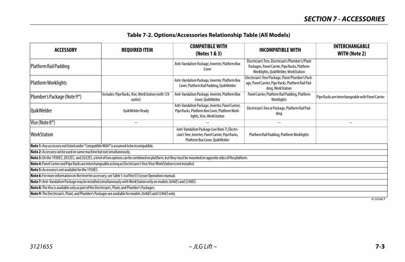
SECTION 7 - ACCESSORIES
7-3
Electrician’s Tree, Electrician’s/Plumber’s/Plant Packages, Panel Carrier, Pipe Racks, Platform
Worklights, QuikWelder, WorkStationElectrician’s Tree/Package, Plant/Plumber’s Pack-age, Panel Carrier, Pipe Racks, Platform Rail Pad-
ding, WorkStationPanel Carrier, Platform Rail Padding, Platform
Worklights Pipe Racks are interchangeable with Panel Carrier
Electrician’s Tree or Package, Platform Rail Pad-ding
-- --
Platform Rail Padding, Platform Worklights
rm.
Table (All Models)
INCOMPATIBLE WITHINTERCHANGABLE
WITH (Note 2)
4150546 F
3121655 – JLG Lift –
Platform Rail Padding Anti-Vandalism Package, Inverter, Platform Box Cover
Platform Worklights Anti-Vandalism Package, Inverter, Platform Box Cover, Platform Rail Padding, QuikWelder
Plumber’s Package (Note 9*) Includes: Pipe Racks, Vise, WorkStation (with 12V outlet)
Anti-Vandalism Package, Inverter, Platform Box Cover, QuikWelder
QuikWelder QuikWelder ReadyAnti-Vandalism Package, Inverter, Panel Carrier, Pipe Racks, Platform Box Cover, Platform Work-
lights, Vise, WorkStation
Vise (Note 8*) -- --
WorkStation Anti-Vandalism Package (see Note 7),Electri-cian’s Tree, Inverter, Panel Carrier, Pipe Racks,
Platform Box Cover, QuikWelderNote 1: Any accessory not listed under “Compatible With” is assumed to be incompatible. Note 2: Accessory can be used on same machine but not simultaneously.Note 3: On the 1930ES, 2032ES, and 2632ES, a limit of two options can be combined on platform, but they must be mounted on opposite sides of the platfoNote 4: Panel Carrier and Pipe Racks are interchangeable as long as Electricians’s Tree/Vise/WorkStation is not installed.Note 5: Accessory is not available for the 1930ES.Note 6: For more information on the Inverter accessory, see Table 5-6 of the ES Scissor Operations manual.Note 7: Anti-Vandalism Package may be installed simultaneously with WorkStation only on models 2646ES and 3246ES.Note 8: The Vise is available only as part of the Electrician’s, Plant, and Plumber’s Packages.Note 9: The Electrician’s, Plant, and Plumber’s Packages are available for models 2646ES and 3246ES only.
Table 7-2. Options/Accessories Relationship
ACCESSORY REQUIRED ITEMCOMPATIBLE WITH
(Notes 1 & 3)
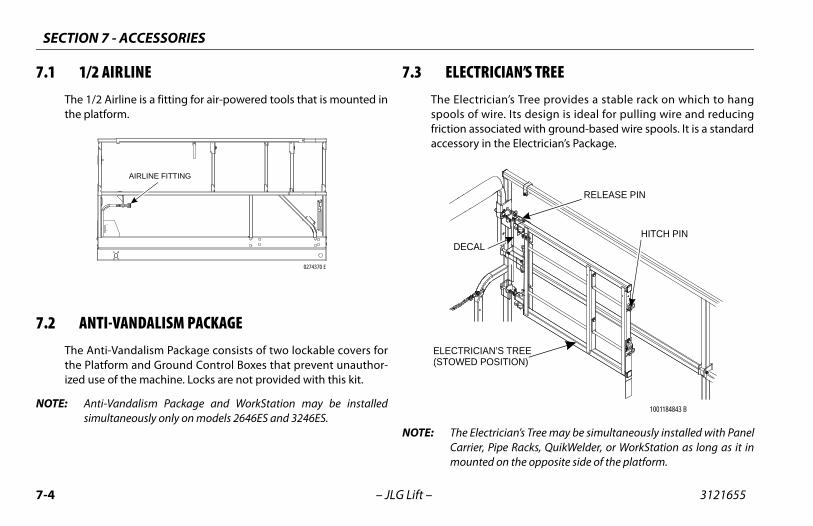
SECTION 7 - ACCESSORIES
7-4 3121655
7.1
7.2
NOT
ICIAN’S TREEian’s Tree provides a stable rack on which to hangire. Its design is ideal for pulling wire and reducingciated with ground-based wire spools. It is a standard the Electrician’s Package.
trician’s Tree may be simultaneously installed with PanelPipe Racks, QuikWelder, or WorkStation as long as it ind on the opposite side of the platform.
1001184843 B
’ TN S REE)SITION
RELEASE PIN
HITCH PIN
– JLG Lift –
1/2 AIRLINEThe 1/2 Airline is a fitting for air-powered tools that is mounted inthe platform.
ANTI-VANDALISM PACKAGEThe Anti-Vandalism Package consists of two lockable covers forthe Platform and Ground Control Boxes that prevent unauthor-ized use of the machine. Locks are not provided with this kit.
E: Anti-Vandalism Package and WorkStation may be installedsimultaneously only on models 2646ES and 3246ES.
7.3 ELECTRThe Electricspools of wfriction assoaccessory in
NOTE: The ElecCarrier, mounte
0274370 E
AIRLINE FITTING
ELECTRICIA(S PTOWED O
DECAL

SECTION 7 - ACCESSORIES
7-5
Replace any missing or illegible decals.
Ensure release pins are intact and function properly.
move release pins and rotate the rack from the stowed sition.
ll the hitch pin for the spool rod to be loaded.
ad the spools onto the rod and replace the hitch pin.
ing the rack into working position and lock into place by placing the release pin.
hen not in use, remove spools and return the rack to the owed position.
3121655 – JLG Lift –
Safety Precautions
THIS ACCESSORY AFFECTS THE OVERALL PLATFORM CAPACITY. REFER TO THE CAPAC-ITY DECAL AND ADJUST ACCORDINGLY.
• Ensure no personnel are beneath the platform.
• Do not exit the platform over the rails, or stand on the rails.
• Do not pull wire by driving the machine.
• Only pull wire along the long axis of the machine with therack in the working position.
• Ensure wire spools rotate freely.
• Return to the stowed position when not in use.
Preparation and Inspection• Ensure the rack is secured to the platform.
• Check for missing or damaged components. Replace ifnecessary.
• Check for loose nuts and bolts. If necessary, torque accord-ing to the Torque Chart specifications in Section 1 of the ESScissors Service Manual.
•
•
Operation1. Re
po
2. Pu
3. Lo
4. Swre
5. Wst

SECTION 7 - ACCESSORIES
7-6 3121655
7.4
Saf
THESTHE FORM
NOT
NOT
ot transport machine without the accessories securedtowed.
re no personnel are beneath the platform.
ot exit the platform over the rails, or stand on the rails.
rn accessories to the stowed position or remove whenn use.
nd Inspectionre all components are secured to the platform.
k for any missing or damaged components. Replace ifssary.
k for loose nuts and bolts. If necessary, torque accord- the Torque Chart specifications in Section 1 of the ES
ors Service Manual.
ce any missing or illegible decals.
ce any torn or frayed straps.
h accessory within this section for specific operation.
– JLG Lift –
ELECTRICIAN’S PACKAGEThe Electrician’s Package includes specific accessories to assistwith different tasks performed by an electrician. This accessoryset includes an Electrician’s Tree, Pipe Rack, Vise, and WorkStationwithout a 12V outlet. See the individual options in this section fortheir description and function.
The Electrician’s Package is available for models 2646ES and3246ES only.
ety Precautions
E ACCESSORIES AFFECT THE OVERALL CAPACITY OF THE PLATFORM. REFER TOCAPACITY DECALS AND ADJUST ACCORDINGLY. DO NOT OVERLOAD THE PLAT-
OR ANY INDIVIDUAL ACCESSORY.
E: The WorkStation may be attached anywhere in the platform aslong as it is mounted to the opposite side of the platform fromthe Vise and Electrician’s Tree.
E: Panel Carrier is interchangeable with Pipe Racks.
• Ensure all accessories have quick release pins and/or vel-cro straps fastened at all times.
• Do nand s
• Ensu
• Do n
• Retunot i
Preparation a• Ensu
• Checnece
• Checing toSciss
• Repla
• Repla
OperationRefer to eacinstructions

SECTION 7 - ACCESSORIES
7-7
el Carrier and Pipe Racks cannot be installed simultaneouslyorkStation is installed, although they are interchangeable.
ADJUSTABLEBRACKET
ECAL
CARRIER TRAY
3121655 – JLG Lift –
7.5 PANEL CARRIERThe Panel Carrier can transport flat sheets or panels to an ele-vated site by positioning them in a channel on the outside of theplatform. It consists of a carrier tray that runs parallel to thelength of the platform and an adjustable bracket mounted to thehandrail to hold material in place.
The panels can measure up to 4ft x 8ft (1.22 m x 2.4 m), or approx-imately 32ft sq. (3m sq.).
This accessory is unavailable for model 1930ES.
NOTE: Panif W
CAPACITY D(ON BACK)
SECTION 7 - ACCESSORIES
7-8 3121655
Saf
MULMAY
THISITY D
WHEWILLWIND
Pre
k for loose nuts and bolts. If necessary, torque accord- the Torque Chart specifications in Section 1 of the ES
ors Service Manual.
ce any missing or illegible decals.
ce any torn or frayed straps.
the carrier tray to the outside of the platform.
e Panel Carrier with material and secure with the ble bracket.
n the panel to its desired location.
e the carrier tray when finished.
– JLG Lift –
ety Precautions
TIPLE MATERIAL-HANDLING ACCESSORIES CAN BE INSTALLED BUT ONLY ONEBE LOADED AT A TIME UNLESS APPROVED BY JLG INDUSTRIES, INC.
ACCESSORY AFFECTS THE OVERALL PLATFORM CAPACITY. REFER TO THE CAPAC-ECAL AND ADJUST ACCORDINGLY.
N THE CARRIER TRAY IS LOADED, THE INCREASE OF AREA EXPOSED TO WIND DECREASE STABILITY. REFER TO THE DECAL FOR MAXIMUM PANEL SIZE AND SPEED.
• Ensure no personnel are beneath the platform.
• Do not exit the platform over the rails, or stand on the rails.
• Remove the tray when not in use.
paration and Inspection• Ensure all components are secured to the platform.
• Check for any missing or damaged components. Replace ifnecessary.
• Checing toSciss
• Repla
• Repla
Operation1. Attach
2. Load thadjusta
3. Positio
4. Remov

SECTION 7 - ACCESSORIES
7-9
el Carrier and Pipe Racks cannot be installed simultaneouslyorkStation is installed, although they are interchangeable.
ONT VIEW
BACK VIEW
TIE-DOWN STRAP
LOCKING PINS
1001199182 A
3121655 – JLG Lift –
7.6 PIPE RACKSThe Pipe Racks provide a way to store pipe or conduit inside theplatform in order to prevent rail damage and optimize platformutility when transporting material to an elevated site. It consistsof two racks, attached to the lower handrail, with adjustablestraps that secure the load in place.
This accessory is unavailable for model 1930ES.
NOTE: Panif W
1001199182 A
CAPACITYDECALS
PIPE RACKS(WORKING POSITION)
FR

SECTION 7 - ACCESSORIES
7-1 3121655
Saf
MULMAY
THISITY D
Pre
ce missing or illegible decals.
ce any torn or frayed straps.
are racks for loading, remove locking pins, rotate ck 90 degrees from stowed to working position, and
with the locking pins.
aterial onto racks with weight evenly distributed n both racks. Do not exceed the rated capacity stated
decal.
the tie-down straps at each end across loaded mate- tighten.
ove material, loosen and remove tie-down straps, refully remove material from racks.
l tie-down straps across any remaining material beforeng machine operations.
ot in use, remove locking pins, rotate racks 90 s to the stowed position, and reinstall locking pins.
0 – JLG Lift –
ety Precautions
TIPLE MATERIAL-HANDLING ACCESSORIES CAN BE INSTALLED BUT ONLY ONEBE LOADED AT A TIME UNLESS APPROVED BY JLG INDUSTRIES, INC.
ACCESSORY AFFECTS THE OVERALL PLATFORM CAPACITY. REFER TO THE CAPAC-ECAL AND ADJUST ACCORDINGLY. DO NOT OVERLOAD THE PIPE RACKS.
• Ensure no personnel are beneath the platform.
• Do not exit the platform over the rails, or stand on the rails.
• Do not drive the machine without material secured.
• Return the racks to the stowed position when not in use.
paration and Inspection• Ensure all components are secured to the platform.
• Check for any missing or damaged components. Replace ifnecessary.
• Check for loose nuts and bolts. If necessary, torque accord-ing to the Torque Chart specifications in Section 1 of the ESScissors Service Manual.
• Repla
• Repla
Operation1. To prep
each rasecure
2. Place mbetweeon the
3. Route rial and
4. To remthen ca
NOTE: Reinstalcontinui
5. When ndegree
SECTION 7 - ACCESSORIES
7-11
Do not transport machine without the accessories securedand stowed.
Ensure no personnel are beneath the platform.
Do not exit the platform over the rails, or stand on the rails.
Return to the stowed position or remove when not in use.
on and InspectionEnsure all components are secured to the platform.
Check for any missing or damaged components. Replace ifnecessary.
Check for loose nuts and bolts. If necessary, torque accord-ing to the Torque Chart specifications in Section 1 of the ESScissors Service Manual.
Replace any missing or illegible decals.
Replace any torn or frayed straps.
o each accessory within this section for specific operationtion.
3121655 – JLG Lift –
7.7 PLANT PACKAGEThe Plant Package includes specific accessories to assist with dif-ferent tasks performed in a production plant environment. Thisaccessory set includes Pipe Racks, QuikWelder, Vise, and WorkSta-tion with a 12V outlet. See the individual options in this sectionfor their description and function.
The Plant Package is available for models 2646ES and 3246ESonly.
Safety Precautions
THESE ACCESSORIES AFFECT THE OVERALL CAPACITY OF THE PLATFORM. REFER TOTHE CAPACITY DECALS AND ADJUST ACCORDINGLY. DO NOT OVERLOAD THE PLAT-FORM OR ANY INDIVIDUAL ACCESSORY.
NOTE: The WorkStation may be attached anywhere in the platform aslong as it is mounted to the opposite side of the platform fromthe QuikWelder and Vise.
NOTE: Panel Carrier is interchangeable with Pipe Racks.
• Ensure all accessories have quick release pins and/or vel-cro straps fastened at all times.
•
•
•
•
Preparati•
•
•
•
•
OperationRefer tinstruc
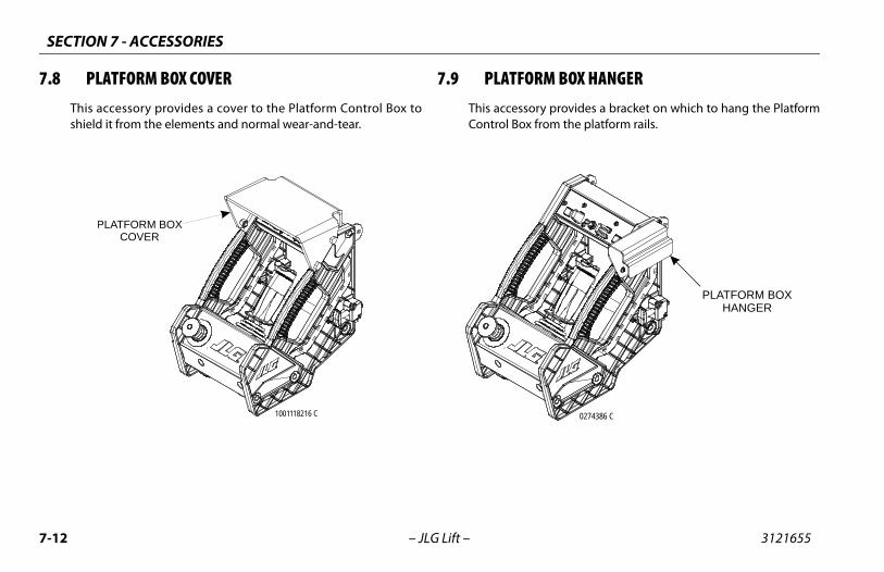
SECTION 7 - ACCESSORIES
7-1 3121655
7.8 RM BOX HANGERry provides a bracket on which to hang the Platform
from the platform rails.
PLATFORM BOXHANGER
0274386 C
2 – JLG Lift –
PLATFORM BOX COVERThis accessory provides a cover to the Platform Control Box toshield it from the elements and normal wear-and-tear.
7.9 PLATFOThis accessoControl Box
1001118216 C
PLATFORM BOXCOVER
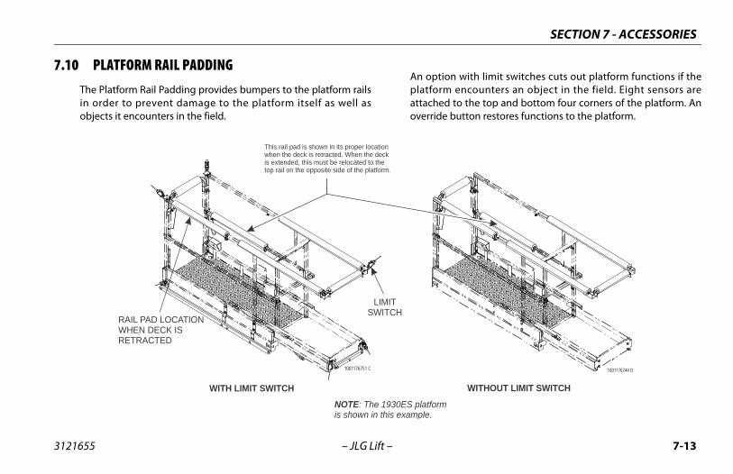
SECTION 7 - ACCESSORIES
7-13
ion with limit switches cuts out platform functions if them encounters an object in the field. Eight sensors ared to the top and bottom four corners of the platform. Ane button restores functions to the platform.
m
1001176744 D WITHOUT LIMIT SWITCH
3121655 – JLG Lift –
7.10 PLATFORM RAIL PADDINGThe Platform Rail Padding provides bumpers to the platform railsin order to prevent damage to the platform itself as well asobjects it encounters in the field.
An optplatforattacheoverrid
NOTE: The 1930ES platforis shown in this example.
This rail pad is shown in its proper locationwhen the deck is retracted. When the deckis extended, this must be relocated to thetop rail on the opposite side of the platform.
WITH LIMIT SWITCH
1001176751 C
LIMIT SWITCH
RAIL PAD LOCATIONWHEN DECK IS RETRACTED

SECTION 7 - ACCESSORIES
7-1 3121655
7.1
work light cable. Flip the On/Off switch to operate.
ON/OFF SWITCH
GHT
GHTLUG
4 – JLG Lift –
1 PLATFORM WORKLIGHTSThe Platform Worklights accessory consists of two 24V lights thatattach to the platform railings.
OperationPlug in the
24V LIGHTS
1001220687 A
WORK LICABLE
WORK LICABLE P

SECTION 7 - ACCESSORIES
7-15
Do not exit the platform over the rails, or stand on the rails.
Return to the stowed position or remove when not in use.
on and InspectionEnsure the components are secured to the platform.
Check for any missing or damaged components. Replace ifnecessary.
Check for loose nuts and bolts. Torque to JLG Torque ChartSpecifications if necessary.
Replace any missing or illegible decals.
Replace any torn or frayed straps.
o each accessory within this section for specific operationtions.
3121655 – JLG Lift –
7.12 PLUMBER’S PACKAGEThe Plumber’s Package includes specific accessories to assist withdifferent tasks performed by a plumber. This accessory setincludes Pipe Racks, Vise, and WorkStation with a 12v outlet. Seethe individual options in this section for their description andfunction.
The Plumber’s Package is available for models 2646ES and3246ES only.
Safety Precautions
NOTE: The WorkStation may be attached anywhere in the platform aslong as it is on the opposite side of the platform from the Vise.
THESE ACCESSORIES AFFECT THE OVERALL CAPACITY OF THE PLATFORM. REFER TOTHE CAPACITY DECALS AND ADJUST ACCORDINGLY. DO NOT OVERLOAD THE PLAT-FORM OR ANY INDIVIDUAL ACCESSORY.
• Ensure all accessories have quick release pins and/or vel-cro straps fastened at all times.
• Do not transport machine without the accessories securedand stowed.
• Ensure no personnel are beneath the platform.
•
•
Preparati•
•
•
•
•
OperationRefer tinstruc

SECTION 7 - ACCESSORIES
7-1 3121655
7.1
6 – JLG Lift –
3 QUIKWELDER™The JLG QuikWelder™ is a self-contained Miller wire-feed welder.It is able to weld light to heavy gauge steel with a single welderand has twice the power of a 110-volt plug-in welder (200 ampsof power). A gas flow control valve and built-in stitch mode areincluded for thin metal operations. A fire extinguisher is mountedto the platform’s front post.
This accessory requires the QuikWelder™ Ready, a cable of vary-ing length according to model that plugs into the machine’s bat-tery and provides power to the station.

SECTION 7 - ACCESSORIES
7-17
he WorkStation is installed, QuikWelder must be installed on opposite side of the platform.
cautions
Y AFFECTS THE OVERALL PLATFORM CAPACITY. REFER TO THE CAPAC- ADJUST ACCORDINGLY.
Ensure correct polarity of leads.
Wear proper welding apparel.
Use correct rod size and current settings.
Do not use electrical cords without ground.
Do not use electrical tools in water.
Do not weld to platform.
Do not ground through the platform.
on and InspectionEnsure all components are secured to the platform.
Check for any missing or damaged components. Replace ifnecessary.
3121655 – JLG Lift –
NOTE: QuikWelder can be installed simultaneously with either thePanel Carrier or Pipe Racks; however, the two accessories mustbe mounted on opposite sides of the platform.
NOTE: If tthe
Safety Pre
THIS ACCESSORITY DECAL AND
•
•
•
•
•
•
•
Preparati•
•
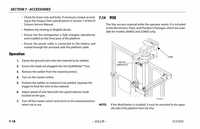
SECTION 7 - ACCESSORIES
7-1 3121655
Ope
ures material while the operator works. It is includedician’s, Plant, and Plumber’s Packages, which are avail-dels 2646ES and 3246ES only.
orkStation is installed, it must be mounted to the oppo- of the platform from the Vise.
VISE
ECALIGHT)
1001184845 B
8 – JLG Lift –
• Check for loose nuts and bolts. If necessary, torque accord-ing to the Torque Chart specifications in Section 1 of the ESScissors Service Manual.
• Replace any missing or illegible decals.
• Ensure the fire extinguisher is fully charged, operational,and installed on the front post of the platform
• Ensure the power cable is connected to the battery androuted through the armstack with the platform cable.
ration1. Clamp the ground wire onto the material to be welded.
2. Ensure the leads are plugged into the QuikWelder™ box.
3. Remove the welder from the stowed position.
4. Turn on the master switch.
5. Position the welder to material to be welded. Squeeze the trigger to feed the wire to the material.
6. Adjust speed of wire feed with the speed selector knob located on the gun.
7. Turn off the master switch and return to the stowed position when not in use.
7.14 VISEThe Vise secin the Electrable for mo
NOTE: If the Wsite side
D(WE

SECTION 7 - ACCESSORIES
7-19
RKSTATIONrkStation offers additional space for storage of tools and
s as well as an adjustable work surface. It is available pow-r unpowered: the powered option has a 12V outlet thats power from the machine’s battery.
0273965 B
WORKSTATION
3121655 – JLG Lift –
Safety Precautions
THIS ACCESSORY AFFECTS THE OVERALL CAPACITY OF THE PLATFORM. REFER TO THECAPACITY DECAL AND ADJUST ACCORDINGLY.
• Do not drive machine with material in the Vise.
Preparation and Inspection• Ensure the Vise is secured to the platform.
• Check for any missing or damaged components. Replace ifnecessary.
• Check for loose nuts and bolts. If necessary, torque accord-ing to the Torque Chart specifications in Section 1 of the ESScissors Service Manual.
• Replace any missing or illegible decals.
• Remove when not in use.
Operation1. Load material into the Vise.
2. Tighten the handle until secure.
3. Begin working.
7.15 WOThe Woobjectered oreceive

SECTION 7 - ACCESSORIES
7-2 3121655
NOT
Saf
THISDECA
ot drive the machine unless materials are properlyred or stored.
nd Inspectionre the WorkStation is secured to the platform.
k for any missing or damaged components. Replace ifssary.
k for loose nuts and bolts. If necessary, torque accord- the Torque Chart specifications in Section 1 of the ES
ors Service Manual.
ce any missing or illegible decals.
orkStation Only:
re the power cable is plugged into the battery, routedgh the frame, and tie-strapped accordingly.
ct 12V outlet and wiring for damage. Replace anyaged components.
djustable work surface, lift the handle and positionorkStation.
0 – JLG Lift –
E: The WorkStation can be attached anywhere in the platformunless the machine is equipped with another accessory, at whichpoint the WorkStation must be attached on the opposite side.
ety Precautions
ACCESSORY WILL AFFECT THE PLATFORM CAPACITY. REFER TO THE CAPACITYL AND ADJUST ACCORDINGLY.
• Return the adjustable work surface to the stowed positionwhen finished working.
• Do nsecu
Preparation a• Ensu
• Checnece
• Checing toSciss
• Repla
Powered W
• Ensuthrou
• Inspedam
OperationTo use the aacross the W
DECALS
0240087 C
ADJUSTABLEWORK SURFACE
(STOWED)
0240071D
WITHOUT 12V OUTLET WITH 12V OUTLET
OUTLET

TRA
NSF
ER O
F O
WN
ERSH
IP
To P
rodu
ct O
wne
r:
If y
ou n
ow o
wn
but A
RE N
OT
the
orig
inal
pur
chas
er o
f the
pro
duct
cov
ered
by
this
man
ual,
we
wou
ld li
ke to
kno
w w
ho y
ou a
re. F
or th
e pu
rpos
e of
rece
ivin
g sa
fety
-rel
ated
bul
leti
ns, i
t is
very
im
port
ant t
o ke
ep JL
G In
dust
ries
, Inc
. upd
ated
wit
h th
e cu
rren
t ow
ners
hip
of a
ll JL
G p
rodu
cts.
JL
G m
aint
ains
ow
ner i
nfor
mat
ion
for e
ach
JLG
pro
duct
and
use
s th
is in
form
atio
n in
cas
es
whe
re o
wne
r not
ifica
tion
is n
eces
sary
.
Plea
se u
se th
is fo
rm to
pro
vide
JLG
wit
h up
date
d in
form
atio
n w
ith
rega
rd to
the
curr
ent
owne
rshi
p of
JLG
pro
duct
s. P
leas
e re
turn
com
plet
ed fo
rm to
the
JLG
Pro
duct
Saf
ety
&
Relia
bilit
y D
epar
tmen
t via
facs
imile
or m
ail t
o ad
dres
s as
spe
cifie
d be
low
.
Than
k Yo
u,
Prod
uct S
afet
y &
Rel
iabi
lity
Dep
artm
ent
JLG
Indu
stri
es, I
nc.
1322
4 Fo
unta
inhe
ad P
laza
Hag
erst
own,
MD
2174
2U
SATe
leph
one:
+1-
717-
485-
6591
Fax:
+1-
301-
745-
3713
NO
TE:
Lea
sed
or re
nted
uni
ts s
houl
d no
t be
incl
uded
on
this
form
.
Mfg
. Mod
el:
____
____
____
___ _
____
____
____
____
____
____
____
____
____
____
____
____
____
___
Seri
al N
umbe
r: _
____
____
____
____
____
____
____
____
____
____
____
____
____
____
____
____
___
Prev
ious
Ow
ner:
___
____
____
____
____
____
____
____
____
____
____
____
____
____
____
____
____
Add
ress
: __
____
____
____
____
____
____
____
____
____
____
____
____
____
____
____
____
____
____
____
____
____
____
____
____
____
____
____
____
____
____
____
____
____
____
____
____
____
____
__
Coun
try:
___
____
____
____
____
____
____
___
Tele
phon
e: (_
____
__)
____
____
____
____
____
____
Dat
e of
Tra
nsfe
r: _
____
____
____
____
____
____
____
____
____
_
Curr
ent O
wne
r: _
____
____
____
____
____
____
____
____
____
____
____
____
____
____
____
____
___
Add
ress
: __
____
____
____
____
____
____
____
____
____
____
____
____
____
____
____
____
____
____
____
____
____
____
____
____
____
____
____
____
____
____
____
____
____
____
____
____
____
____
__
Coun
try:
___
____
____
____
____
____
____
___
Tele
phon
e: (_
____
__)
____
____
____
____
____
____
Who
in y
our o
rgan
izat
ion
shou
ld w
e no
tify
?
Nam
e: _
____
____
____
____
____
____
____
____
____
____
____
____
____
____
____
____
____
____
___
Titl
e:__
____
____
____
____
____
____
____
____
____
____
____
____
____
____
____
____
__
��
����
���
�
��
� ��
�
�
��
��


JLG Industries, Inc.1 JLG DriveMcConnellsburg PA. 17233-9533USA
(717) 485-5161 (Corporate) (877) 554-5438 (Service) (717) 485-6417
www.jlg.com
JLG Worldwide LocationsJLG Industries 358 Park RoadRegents ParkNSW 2143Sydney 2143Australia
+6 (12) 87186300 +6 (12) 65813058
Email: [email protected]
JLG Ground Support OudeBunders 1034Breitwaterstraat 12A3630 MaasmechelenBelgium
+32 (0) 89 84 82 26Email: [email protected]
JLG Latino Americana LTDARua Antonia Martins Luiz, 580Distrito Industrial Joao NarezziIndiaatuba-SP 13347-404Brasil
+55 (19) 3936 7664 (Parts) +55(19)3936 9049 (Service)
Email: [email protected]: [email protected]
Oshkosh-JLG (Tianjin) Equipment Technology LTDShanghai BranchNo 465 Xiao Nan RoadFeng Xian DistrictShanghai 201204China
+86 (21) 800 819 0050
JLG Industries DubaiJafza ViewPO Box 262728, LB 1920th Floor, Office 05Jebel Ali, Dubai
+971 (0) 4 884 1131 +971 (0) 4 884 7683
Email: [email protected]
JLG France SASZ.I. Guillaume Mon Amy30204 Fauillet47400 TonniensFrance
+33 (0) 553 84 85 86 +33 (0) 553 84 85 74
Email: [email protected]
JLG Deutschland GmbHMax Planck Str. 2127721 Ritterhude - IhlpohlGermany
+49 (0) 421 69350-0 +49 (0) 421 69350-45
Email:[email protected]
JLG Equipment Services Ltd.Rm 1107 Landmark North39 Lung Sum AvenueSheung Shui N. T.Hong Kong
+(852) 2639 5783 +(852) 2639 5797
JLG Industries (Italia) S.R.L.Via Po. 2220010 Pregnana Milanese (MI)Italy
+39 (0) 2 9359 5210 +39 (0) 2 9359 5211
Email: [email protected]
JLG EMEA B.V. Polaris Avenue 632132 JH HoofdorfThe Netherlands
+31 (0) 23 565 5665Email: [email protected]
JLG NZ Access Equipment & Services2B Fisher CresentMt Wellington 1060Auckland, New Zealand
+6 (12) 87186300 +6 (12) 65813058
Email:[email protected]
JLG IndustriesVahutinskoe shosse 24b.KhimkiMoscow Region 141400Russia Federation
+7 (499) 922 06 99 +7 (499) 922 06 99
Oshkosh-JLG Singapore Technology Equipment Pte Ltd.35 Tuas Avenue 2Jurong Industrial Estate Singapore 639454
+65 6591 9030 +65 6591 9045
Email: [email protected]
JLG Iberica S.L.Trapadella, 2Pol. Ind. Castellbisbal Sur08755 Castellbisbal BarcelonaSpain
+34 (0) 93 772 47 00 +34 (0) 93 771 1762
Email:[email protected]
JLG Sverige ABEnkopingsvagen 150176 27 JarfallaSweden
+46 (0) 8 506 595 00 +46 (0) 8 506 595 27
Email: [email protected]
JLG Industries (UK) Ltd.Bentley HouseBentley AvenueMiddleton, Greater ManchesterM24 2GPUnited Kingdom
+44 (0) 161 654 1000 +44 (0) 161 654 1003
Email: [email protected]