operation castle, project 2.5a, distribution and intensity of
TRANSCRIPT

UNCLASSIFIED/UNLIMITED.
,j@F- -... “-
TechnicalReport
distributed by.
0//@&~. ; , Defense Technical Information Centerw. DEFENSE LOGISTICS AGENCY
Cameron Station .Alexandria, Virginia 22314
UNCLASSIFIED/UNLIMITED

.-/ -“
,.
UNCLASSIFIED
‘i
CLASSIFICATION CHFtNGEDT’): UJNCE,ASSIFIEDFROM: e ~~mm Zzl
232!5- ‘
AUTHORITY: -w~-/ 8
—;- ~——-“
* . ‘--fl

---
,:,.,.’2
,’

,, .—.— . . .
./
....
(
.:*b”
,.- -,-J+
!.
!’
‘.
t.
,.”
.,.
‘ ,.. . i ‘.
{’ ., ..,“$,‘.
,...., ,
,“., ; :,
. .
. .-. .
,...-
. .i,
.. .,,
s
. ,.
. .
.
.— —. —.. —. ..--. — — . . -. . .- ---------- ----
\
SECURITYMARKING
w limitedstatus.uaioss.Wwise
printoutsMUSTba
cd lhisraw’Iappiies
marked.
nnrked accordingly.
4
%nig document contains faformation affectingthe RatIonalDefenseof the United Std6s within the ❑eaning of thoEspionageXmmY, Title 18, U. S. C., Section793 and794. Its transmissionor the rvvolationof its contmtsh any meaner to an unauthorizedperson is prohibitedw 1ST,* ..—- —
‘~~
I1
,,
“OMEHALF ORIGIUAL SIZE”. <1
/.
atwiuwnt A

. ,/,/’
‘, . .
-. #
-, t.
‘,. .,
.. . . . ...% ‘> ’...,.. .. . 1
., ’,.” -.}.-,+ .:$* .
<.
,,,,,”,
,,
WMASSIFIED/
z’
. . .
,,
‘w
.
. . . .
..
\
.. .

,..
.,,.<.
,,.
,.
.’.’
.
,,,.../-,.
. .
WT-915
This document consistsof 172pages
.rio. 30 -of 240copies,S&;ISSp~’w ●-I*
‘::3
.
OPERATION CASTLE-. ,~ ..’
.,. -4
PrOject 2.5a
DISTRIBIJTION AND INTENSITY OF FALLOUT
REPORT TO THE SCIENTIFIC DIRECTOR
by
R. L. Steton
E. A, Schuert
W. W. Perkins .
T. H. Shirasawa1.,
H. K. Chan. .- ,J
.’::&
RESTRICTED DA”(A rTt, is document contains restricted data as
defined In the Atomic Energy Act of 1954.
Its transmittal or the disclosure of )ts - - . . .contents In any manner to tin unauthorized i, -.,.
person is prohibited.. ,!.4
●
L!.S.Naval IhdiologicalDefense UboratorySm Franciscg24,C:~lifornia
.
.t

,/,f. .
. .-
.-7-”,.●
,),’
, ,,‘>--’-.
..
..,
,, ./ .’
,/
~ LEROY,/’
kENGCllI
‘\‘,, BR~E.. (:;’\\ ,,,.
CLYDE ~ ““’JApTaN
fjAvIO\T-”- – 4
.:’> DEEP ENI~Afa
$
..ELMER——--._=_ ,
,’,,.(PAWR”
,,:A;,$~
/
,-, ‘.+?
,-. .’
FRED ., ,,.; ; .
, /
‘-,X :,,...,,.. . .,.. . ..’
., :... ENIWCTOI(.,, , ..
,.,. .- -.
. ..
-.
-.J’
I
,..
. .
..
. ... ‘.. .t. ...-..” : ‘.,.....-.
2
.?

.;,
.“,.--
,-
,,/
/
,’
.Z.
.,
)“
-9
..
0
u
-..
“ J
..-
.,
-.
-.
.,“,.
,:----,.
-.. -L
[’:,
/’
.
. .“
,.
.
..
. .
--
-..
...
\
/..
. .
9
..
4.
.

. ..L.-
... .
.“ .
ABSTRACT,..:. 1:“-Y
The objective of this project was to document the distribution.’
and intensity of fallout from all shots at operationCASTL14.Data uere obtained for Shots 1, 2, 3, L, and6 by nse of land
-.,/-
stationsyanchored lagoon stations$ and free-flattig sea gv!.tions.Acompleti analysis of the Shot 1 fallout to 300 nautic~ ~les do~w~dincluding the develo~ent of anexprimental model based on falloutparticie trsjectoriec is presented as well as data on Shot 2 falloutto 50 nautical miles downwind and the close-in fallout from Shots 3, 4,and 6.
!
Gamma fields from fallout decayed at rates differing from the t-1*2approxinntion camnonly applied to fission weapons.
Fallout fram the surface land detonationswas in the form of irreg-ular solid particulate. The geometricmean particle diameter decreasedwith the distance from the shot points; for Shot 1 the geometric meannried from 112 P at Bikini.Atoll.to 45 P at utifik Atoll. The averagedensity oi the solid particles from Shot 1 was 2.36 g/cu cm. Xd.ttledata were obtained on tne nature of the fallout from over-water detona-tions. There was some indirect evidence that the fallout 50 nauticalmiles downwind from Shot 2 arrived as a fine mist or aerosol. l’he~teof arrival of fallout at distances close to surface zero was character-ized by a rapid rise to a peak; the maximum level of radiation occurredwithin the first half of the period of fallout.
A continuous 100 hr unshielded exposure after the detGIMtiOn of a154fl de”.ce on land, will result h a minimum free field total dose of100 r over an area as large as 25,000 sq mi.
There is developed an experimentalmodel that protides a means ofreconstructingfallout patterns from limited gamma field data and par-ticle tmjectories as determined by comprehensiveanalyses of themeteorological situation.
‘..-
/
-,
.“.
.. .
8.-,.
.
5
‘\

. .
,.,. -.
. ...;
.,,-,.
. .
,.-.c
.
.,
1
*
>
ACKNOWLEDGEMENTS
The ruuydtude of this project required the sup~ort and cooperationof many groups and individuals. The authors wish to thmlc the ProjectOfficer, S. R. Tompkins, for his sincere interest and help during theentire course of the work. They are al:m indebted to the follouing fortheir effective contributionsto the project.
~ u. s. !Jawd ~ Ik?f~ a 1e~~)
1. Fourteen additional investigatorsfrom the Chemical ‘lechnolo.gyDivtsion participatedin the field phases of the prcject. R. ~. so~e~P. E. Zi~n, W. B. Lane, and E. C. Evans 111 assumed responsibilitiesas team leaders.
2. The engineering Divisicn supplied cr~ftmen and teckmiciansfo: field work in addition to services in the devclopent and procure-ment of instruments.p.A. CoveyP D.F. c~vell~ LTJ~ ~CFO‘“~son~ ‘lm$ ad‘J. L. Snapp nade sib~ificant contributionsin the field.
3. The Instruments branch of the Nucleoaics Ditision assistedextensively in the pre+per~tion testtig of buoy identifiersand producedjinstallei, and serviced the trmsmitter system used. Two en~ineers,H. L. Gottfried and F. A. FUmads, made signific~nt.contributions in thelabor~to~~ and in the field.
4. The Analytical and Standards Branch of the Chemical TcchnololvDivision provided much help in the treatment ad analysis of swples.w. H. Shl@m and J. R. hi ma<e significant contributions.
5. The foilw~g project zcba ~erso~el WVe wlwble as~istdncein the field: w. J. Heimant ii.Cole, J. F. kestaner, 5. SinCer, -dM. J. Nuckolls.
6. In addition to an effective contributicmin the field, J. H.McCampbell of Military Evaluations Group assicted in particle sizeanalyses.
7. C. A. Adams of Chemical Physics Bfinch, Chemical TechnologyDivision tissistedin ev~luatimd particle size data.
8. D. D. Cole of ?rocurcmentLiaison an:lMaterials Ccntrol I)ivi-sion assumed responsibilityfor material cmtrol in the field and madea significantcontributionin handling return shipents cf samples andequipwnt.
9. CDR H. L. Leichter, USN, LCDRF. J. Sisk, USN, ml UDR J. Cady,TJSIJ,projects offiCer6 at US~~~L$ contributedextensively to inves-~iGcting
~
‘,‘P
. .

..
.... . ..,,,r?.’.,
.
9+-‘$.
‘$ “\,<.w., .,.=
7‘.,. .,f -
‘$,”.:b ..’
.. \
“\.’!.;,
.. .‘%‘
~., ,.:
..’..
J,
and testing buoy irientificationsystems.
Other
1. The Naval Task Group under the Commtindof RwJ1 H. C. Brutor:,U3!J,protided extensive support in ccmductin~ the se~ phase of theproject. The follo};ingNaval units participated:
ULS SICW, ATii-75ES APACHL’,ATF-67WS TA’M’XX?l,ATF-lIf+USS LkrL&ON, JDE-719ES RENSWW, DDE-499
2. Search aircraft support was provided by Commanding officer,VP-29, under ‘CTG7.3. wfia it.J. Mooten, CSN, and his air CreU contri-buted significantlyto the project, both in ewduating and testing buoyidentificationsystems and in conducting the sea rhase at the om=ation.
3. CDRV. A. Clark. WY’. Staff Air Cfficer, and CDR M. M.Schmidling, USN, Staff Cper~tions Officer, CTG 7.J, provided specificassistance to the project.
L. C&T J. E. Smith, USN, Commander, Escort Destroyer 2ivision 12,d~wcted sea @ase operations during a portion of the operation.
5. Commander, Air Forces Facific Fleet, arran~ed for, conducted,and evalucted tests of buoys and identificationsystems proposed hy thelaborato~. LCDR d. C. Barton, CSHR Staff, CQl~~l~AC~ condu~:tedthetests.
6. Chief, Bureau of Ships, provided for installationof specialradio directim finding eqtipment on Task Force ships. KU arrm~enents
were handled through Code 348 by LCLR J. 2. Coates, WN.7. Project 6.4, TU-13, provided fifo~~ticn on the loc~ticfiOf
fallout areas. U. J. Armstrong made significant,contrib~;tionsin thisregaxd.
8. Lt Col E. A. lirtell, USA, Program director of Progr(am2, con-tributed extensively to the pleming an~ directim of project oper~tionsat the site, and to the review of t,tisreport.
9. The followimg Naval enlisted personnelwere assiGaed to theproject during the operation:
MENAELL, F. J., EM ~,/CRAYM’4D, L. G., : ;$MLLER, N. S.,
. .
.
-.
●
j.1.--
*,. ,:.
‘ ..41..,
“~,‘,,
--, --/,
. ..- -- ,,,,“
\‘\ .
1,
~..\
.
8

,,‘..>/
,1. .,
- 1“
- ..\:*
,’,!
,,.‘,
.;.:
...- ..%M “!
\,. .,,:,. ..-. ..,- ---
.=. ..-... .
. .‘.
..’ .\.
..\!,
./. . .. .. .
b“
This report is one of the reports presentingthe results of the34 projects Prticipathg h the F!lit:tryEffects Tests Frogrsm cfOper~t.ionCAL’TLL,which included six test deton~tions. For readers
interactedin other pertinent test info-tion$ reference is made to‘,;7’-934, ~h+iqm!l P&port of the Comander. Task Unit 13. ProPrams 1-Q,
~illtary Gffects rrogram. l’hissumnaxg report includes the foliowinginformti:n of possible &eneral interest.
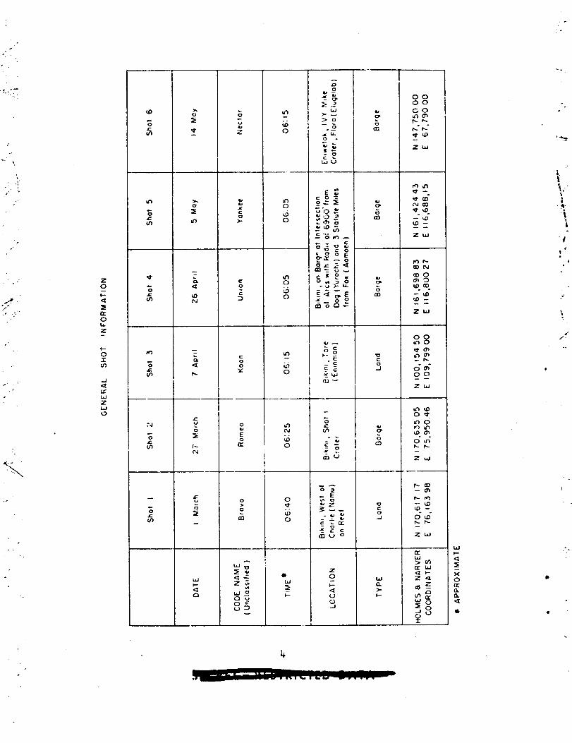
a. An over-all description of e:ch deton~tion, includingyieid, hei~ht of burst, ground zero loc~tion, time ofdetonation,ambient atmospheric conditions ct detonation,etc., for the six shots.
b. Liscu sion of all project results.C. A LLULLIZry of etch project, including objectivesand
re~ults.d. i.complete listin: of all re~,ortscoverhg the
~,ilikx-~.iffectsi’estsrro~rsm.
. ..
},..,,
\
. ‘i
‘.\,\,
i“
‘,.,-,.-

.2.
CONTENTS
-..
●
AMTRACT “ . . .
ACKNO!’UDGL!ENTS
70RETCPD . . .
ILLUSTIUTIONS .
TABXJ3S . . . .
●
●
●
✎
●
● ☛☛✎
● ☛✎✎
✎ ✎✎☛
● ☛☛✎
✎✎☛✎
CHAPTER1 INTRODUCTION
8
●
✎
●
b
,
●
✎
✎
●
✎
●
.***
. ..*
.*. .
● ☛☛☛
● ☛☛☛
.0. .
1.1 Previous Fallcut Studies . .1,1.1 Nuclear i’~sts. . . .1.1.2 High Exnlosive Tests
1.2 Objectives . . . . . . . . .
CMWTER 2 OPERATIONS . . . . , . .
2.: Experiment Design . . . . . .
●
●
●
✎
✎
●
✎
●
✘
●
✎
●
2,101 Predicted Gamma Fields2.1.2 Sampling Stations . . .
2.1.2*1 La~d Stations
●
✎
✎
✎
●
✎
✎
●
●
●
●
●
●
●
✎
2.1.2.2 Lagoon St~tions2.1.2.3 Sea Stati.on9 .
2.2 Land and Lagoon P’kso . . . . . .2.3 Sea Phase .O . . ..o . . ..O
2.3.1 Pretest Prepmations . .2.3.2 Rehearsals . . . . . . .2.3.3 Shot Participation . . .
2.3.3.1 Shot 1 . . . .2.3.3.2 shot 2 ● . ● .2.3.3.3 shot 4 . . . ●
2.3.3.4 Shot f . . . .
.
●
✎
✎
●
✎
✎
●
●
✎
✎
●
●
b
.
.
●
●
●
●
.
●
.
●
.
●
2.3.3.5 5hot6 . . . . .
●
✎
●
✎
●
●
✎
✎
✎
✎
●
●
●
●
✎
●
●
✎
✎
●
●
●
●
●
●
●
✎
.*
90
. .
● *
● S
.*
.*
. .
● *
● *
● *
● *
● *
● *
.*
● *
● *
● *
.s
● *
.*
● *
● *
. .
.-
● *
. .
●
✎
●
●
✎
●
D
●
.
●
●
●
●
.
●
●
●
●
●
●
●
●
8
●
9●
.**
●
●
●
●
✎
●
●
●
●
●
●
●
●
✎
●
●
●
✎
●
●
●
●
●
✎
●
●
●
●
●
●
✎
✎
✘
●
●
●
●
●
●
●
●
●
●
●
✎
●
●
●
●
✎
●
✎
●
●
●
●
●
●
●
●
●
●
●
●
Q
●
●
●
●
●
●
●
●
●
●
●
●
●
.
●
●
●
●
●
●
●
●
●
●
●
●
●
●
●
●
●
●
●
●
●
●
●
●
●
●
●
●
●
5
7
9
u
16
19
19192020
21
2122
:24u28282829293131313131
11
--
.. . . .

t
., ,’1/
. .
“-. .
C1iA~ER 3 IESTRU1.ZM’ATIQK.. . . ..=O ● *****””**
3.1 Description and Operation of the Equipment . . . . . , ●
3.1.1 Total Fallout Collectors . . . . . . . . . . . .3.1.2 Differential Fallout Collector . . . ● ● . s ●
3.103 FilmBadgePack . . . . . . ● ● ● ● ● ● ● ● ● ●
3.1.4 Gamma Time-IntensityRecorder . . . . . . . . .3.1.5 Prototype Collecting Devices . . . ● . . . . . c3.1.6 Tr~ggors . . . . . . . . . . . . . . . . . . .3.1.7 Free-FloatingBuop . . . . ...*.*.***
3.:! Evaluation of Stations and Equipent . . . . . . . . . ●
3.2.1 Island Stations . . . . ● ● . ● ● . . c . Q ● ●
3.2.2 Lagoon Stations . . . . . . . ● . ● ● ● ● ● ● ●
3.2.3 Free-FloatingSea Stations . . . . . . . . . . .3.2.4 Total Collectors . . . . . ● . . . . ● ● c ● ● ●
3.2.5 BeltSampler. o . . . . ● . ● ● ● O ● ● ● ● ● ●
3.2.6 Liquid Droplet Sampler . . . . . . . . . . . . .3.2.7 Electrostatic Precipitator . . . . . . . . . . .3,2.8 Trigger Devices . . . . . . . ● ● ● . ● ● ● ● ●
3.2.9 Gma Time-intensityRecoIder . . . . . . . . .
CHAPTER 4 SAMPIJ3ANALYSES AKm DATA ~UCTION . . . . . ● ● ● ●
4.1 Sample Analysis . . . . . . ● . z. . 9 . . ● Q ● ● ● “
[.2
CHAPTER
5.1
5.2
5.35045.5
5.6
4.191 Counties Technique . . . . . . . . . . . . . . .4.1.1.1 ~otAl Collectors . . . ● . ● . ● ● ●
.t.1*1.2 Gum.ed Paper Collectors . . ● . . . .L.1.1.3 Differential Yallout Collectors . . .
4.1.2 Particle Size ‘Measurements. ● . . .Lel.> Particle Density Measurements . . .DataXeduction . . w . . . . ● ● ● ● ● ● ●
4.2.1 Total Collectors . . . . . . . ● 9 ●
5 CMRA(XERSSTICS OF FALL~ , . . . . . ●
Gmma Field Decay. . . . . . ..=*=***5.1.1 Theoretical and Field Decay . . . .5.1.2 Experimental Laboratory Decay . . .Par?.icleSize . . . . . . ● ● . ● c ● ● ● ‘5*2.1 Shot 1, Close-in Fallout . . . .5.2.2 Shot 1, Outer Island Fallou~ . . .5.2.3 Shot 6, Particle Size . . . . . . .
Iktio of Active to Inactive Particles . . .Particle Density . . . . . . . ● . ● ● . ● ●
Gross Physical Characteristics of Fallout .-.
Surf~re Lam+ Shots . . . . . . ● ●5.5.15.5.2The of
Surface \7[lterShots . . . . . . . .Arrival oi’%llout. . . . . . . ● .
● ☛☛☛☛☛
● 9****
● *O*e-
● **0**
● *P***
● ☛☛☛☛☛
● ☛☛☛☛☛
● ☛☛☛☛☛
● ☛☛☛☛☛
● *9***
● *****
.**..*
● *****
..e*.*
● *99**
● *Ore**
● *****
● **=**
35
35353737373739393941414242424243f4343
44
444.4L5L545L5464646
50
5050555559
2;646L
67
z67
12

5.7
695.6,15.6*25.6035.6.&Rate of5.7.15.7.2
Shot 1SJlot2Shot 3Shot 6
● ☛☛
● ✎☛
● 9*
●
●
s
● ☛
● ✎
● 9
●
●
●
.●
●
● ☛☛☛
9***● ***
●
✎
9
●
●
●
●
●
●
●
●
●
●
●
9
●
.
●
●
●
●
●
●
●
●
●
●
●
●
●
●
●
●
✎
●
✎
●
●
●
●
●
●
●
✎
✎
9
.
●
●
●
●
●
●
●
●
●
●
●
●
9
●
●
.
●
●
●
●
.
●
●
●
●
●
.
...
●
●
☛
●
●
●
●
●
✎
.- 7070707070
73
74
74
;77~o
80PO8284
2
R585889(792
92
101
1(?11011021(J3
104
1041w+104104
‘.● ✎ ● ● ● ●*
Arrival-o? IntegratedDose .Rate of Arrival .Total Dose . . . .
●
✎
● *****a ● .
. ..**** ● *
.6 PRWARY FALLOUT PATTERNS 9***.** ● * ● ●
Shots 1, 3, 4, and 6Fallout Near Ground Zero for601.1 Shea l.......6.1.2 Shot . . . . . . .6.1.3 Shot L.......6.1.4 Shot6. . . . . . .
i;:
. -._&4
..,
6.2 Extended Fallout Pattern for6.2.1 Measured Field VaY~es of Residual GammaActivity6.2.2 Determination of Experimental Mdel - Shot’1 ●
6.2.3 Experimental Data Armlied to Model Evaluaticm6.2.L Determination of Particle Tra~ectories . .6.2.5 Consideration of Cloud Dimensions . . . .6.2.6 Detemr.inationof Axis of Symmetry of the
Fallout Pattern . . . . . . . . . . . ● .
6.2.7 Construction of the Fallout Pattern . . .6.2.8 Evaluation of the Shot 1 Fallout Pattern6.2.9 Material Balance for shot 1 “. . . . . . .6.2.10 Growth of Shot 1
Shotl . . . . . . .,.. . 9
. ,,.:. .
●
●
●
●
●
●
●
●
●
●
✎
●
✎
●
●
✎
●
●
●
✎
●
✘
●
✎
✎
●
☛
●
“
●
.
●
.
●
●
●
●
●
●
●
●
●
☛
✎
✎
✎
✎
Fallout Pattern with Time
●
✎
✎
●
✎
●
● ✎
● ☛
● ✌
● ✎
● ☛
● a
6.3 Extended Fallout Pattern for Shot 2 ● ✎☛
● ☛✎
✎ ✎ ✎
● ☛✎
✎✎☛
● ✎☛
●
●
●
●
✎
✎
CHAPTER7 SUMMAHY . . ● . . ● ●
●
●
●
●
● *O
● **
● **
● **
.**
●
●
●
✎
✎
●
✎
●
✎
●
7.17.27.37.L
General Observations . .Plans for llmther work .Specific Conclusions .Recommendations . , .
,.,
APPENDIX A Sl+m 4, OPERATION HAN - EUOY PHASE, PROJECT 2.5Q
A*1 Plans and Preparation . . . . . .A.2 Laying Procedure, Co=nlete Array .A*3 Laying Procedure, Partiel Array .A.f, Procedure for Advancement or DelayA.5 Recovery Procedures . . . . . . .A.6 Messages to ATFts From CTG 7.3 . .A.7 Messages From f.’E‘s to CTG 7.3 . .
● ☛☛☛☛☛ ● ☛☛☛
● 9m*e* ● *.*
● **m** ● ***
of Shot.....105
: 105● 105
● 99.9** ● **
● *.**** ● **
. . . . . ● -0=0
..“”

,,
f
1
AFHXDIX B GNJ!A ACTIVITY KSASIJRENENTSFOR THE TOTAL AND GXLXD?ME?COLLECTOM o....... . . . . . . . . ..1o6
,
PARTICLE SIZE DIST.RIBI;T’IXMID PERIOD OF FALLOUT DATA,SP(YISIAXD 6 . . . . . . . . . . . . . . ..*os
FALLOUT PART7CLE DENSITY, SHOT 1 . . . . . . . ● ●
PARTICLE FALTLIliGRATES.... .....*.00*.
N3’T’E.HMINATIOEOF L’TERIAL MIMCE FOR SHCT 1
115
134
137
APPEHDIX D
A?,7EE\~IXC
AP?EXDIX F
#
..
—FALLOU’TPATTEW(r/hratl hr).....-.~.oo
F.1 ~nr Cent Of Device Activity at Time (t]. ● . . . . . . ● .
F.2 iklation of Deposited Activity to Gamma Field at 3 ftfor an Infinite Contaminated Plane . . . . . . . . . . .
Fo~ Calculation of Material Balance . . . . . . . . . . . . .F.L Raction of the Device Collected in Total Collector~
Station 251.03 . . . . . .oO. .O. O* O=OO ● Q*
APPE1iDIXG STATION J.NSTRUNNTATIOI[ . . . . . . . . . ● . . . .
APP12THX H MRSMLL ISLANI OCEM CUF.~&NTSAS 5WT’5’5MMIDFRCN
l&3●
143
I.&LX6
U6
-,
$48
‘/ “,.,
.
.-FREE FLOATING SCOYS. . . . . . . .. o*..*
BIBLIOGMPHY . . . .. O.C. •..*~.*=c**~***
8*
● a
● *
● .
● *
● 0● *● *● m
166
,, ,.,,, .
ILLUSTRATIONS
IIRsicSampling Array Pro~sed for allShotsExcept Echobgoon snd Island Station Array for Bikini Atoll . . .LaRoon Ar:-ayfor Eniwetok Atoll ● . . ● . . ● w ● ● ● ●
La~~n Station Deiny Placed . . . . . . ● ● . ● ● ● “ ●
Shot 1, Flanned Sea Station Array . . . . . ● . ● ● ●
Shot,l,5ea Station Array . . . . . ...**. ● “*oshot 2, Z9fiStation Array.... . . ...*****=
23252627
E34
2.12.22.32.1+2*52.62.7
/“
9,.
,:.,,
.1
,,
-.8 ,.

. . -
,
,“,.-/
. . ..
,.
.,./.’
/.
/
3.13.23.33.4L.1
4.2
5.1
52
5.35.45.55.65.75.8
5.95.105.115.126.16.26.36..46.5
6.66.76.86.96.106.116.126.13
6.14C.1C.2C.3C.h
Total Collector ...*. ● ..00 =0 coo so” ● **** 36
DifferentialFa?.loutCollector . . . . . . ● . ● ● s ● s ● ● ~~Light-AstuatedTrigger Assembly . . . . . . . . . . . . . . . .+Free-floatingSea Station Eeing Launched . . . . * o . ● ● . uRatio of Gamma Infinite Field Measurementsto Q1tivdentGamm MeasurementsFro.nthe Total Collector (~/hr at0+4days) . . . . . . . . . . . . . . ● . ● ● ● ● “ ● ● ● ● mRatio of Gamma Infinite Field Measurements to %uivalenttiia Measurements From the Gummed Paper Collector(mr/’hrat 0~4 days) . . . . . . . . . Q...0000D*”$~Experimental and Calculated Beta Dt~caYCurves . . . . . . . sCalculated Gamm Decay Curve and ExperimentalGammaIonizltionDecay Curve for Shot 1 . ● ● ● ● o ● ● ● ● ● ● ● ● 52Cmmosite Gamma Iotizatio& Decay Curve . . . . . . . . . . . 54-. ~ —.shot 1,Shot 1,Shot 1,Shot 1,Shot 6,StationShot 1$Shot 1}shot 1,Shot 3,Shot 1,Shot 3$Shot 4,Shot 6,Shot 1,
Composite Particle Size Distribution . . . . . . . . 60Cumulative Particle Size D3.stribution. . . . . . . . 61outer Atoll Farticle size Distribution . . . . . . . 62Outer Atoll Cumulative Particle Size Distribution . . 63Cuzmlative Particle Size Distribution,Alice. . . . . . . ..= . . .= . . ● ● ● ● ● ● ** ~f
Ratio of Active to Inactive particles . . . . . . . g 66Fallout Particulate,St~tion 250.04 . . . . . . . . . 68Integrated Gamma Dose, Station 251.03 . . . . . . . . ?lIntegrated Gama Dose, Station 251.03 . . . . . . . . 72Close-in Gama Fallout Pattern (r/brat 1 hr) . . . . 76Close-in GLWQ Fsllout Pattern (r/brat 1 hr) . . . . 78Close-in Gamma Fallout Pattern (r/hr at 1 hr) . . . . 79Close-ir Cama Fallout Pattern (r/hr at 1 hr) . . . . 81Calculated Direction of Fallout From Analysis of
Pati,icleTrajectories . . . . . . . . . . . . . . . . . . . ● ~Shot 1, ReconstructedComplete Fsliout Pattern (r/hr at 1 hr) WJANGLE Surface Shot Scaled to 15 ~ (r/hr at 3 M). . ● ● ● ● ~Shot 1, ReconstructedFallout Pattern at 1 hr . . . . . . . .Shot 1, ReconstructedFallout Fattern at 3 hr . . . 9 ● ● ● ● 94Shot 1, ReconstructedFallout Pattern at 6 hr . . . . . . . . 95bhot 1, ReconstructedFallout ?attern at 12 hr . . . . . . . %Shot 1, reconstructedFallout Pattern at M b . . . . . . . ylShot 1, Calculated Time of Arrival and Ces=tion of FalloutBased on Calculated Farticle Tr::jectories. . . . . . . . . ● &UShot 2, Fallout Pattern (r/hr at 1 hr). . . . . . . . . . . .Shot 1, Particle Size Distribution,Station 250.04 . . . . . U6Shot 1, Particle Size Distribution,Station 250.06 . . . . . U7Shot 1, Particle Size Distribution,St~tlon 250.22 . . . . . 138Shot 1, Particle Size Distribution,Station 250.24 . . . . . n9
,,
/’>“’
15

/
fY
-+
.
C*5C.4C*7,-~-*U5.9C.loC.ilC*12C*13G.14C*15c.16C.17C.18L.1
71-.~z;:15.25.3rt. ● -4qc. ● ,
5.65.76.1
6.2
6.2
6.4
: hot 1,shot 1,shot 1.$S!-lot6,Shct 1,Shot 1,Chot 1$Snot 1,shot 1,Zhot 1,S!lot1,shot 1,~~~~,~~eshot’s.
karticle 2ize Distribution,Station 251.04 . . . . . . 120l-articleSize Distribution,Station 251.06 . . . . . . 121Particle Size bictributian~Stition ~z51*10● ● ● ● ● ● 122Farticle Size Distribution,Stztion Alice . . . . . . 123‘Tir.:of irri~dl znd reriod of Fallout, Stitim 250.05. 124‘limeof Arrival and keriod of i’ailou~,Station 250.M. 125Tine of Arrival and Period of Fallout, Station 250.22. 126‘lineo? i,rriv~lmd Period of Fallout, ~t~ticm 250.21+.127Time of Arrival and ?eriod of Fallout, St~tim 251.04. 128Tine of iirriv~land Period of Fallout, Station 251.05. 1.29The of .-rrivaltindPeriod of Fallout, St&tion 251.ti. 130Ttie ~f l.rriv~land Period of Rllout, Station 251.10. 131G: R>lative Eack;;roundActititi~,Station 251.09 . . . 132
Area: of *applicabilityin Calcul&tinG
TABLES
hlloutj Station Alice . 133Terminal Velocities . . MO
.
●
..\
Fr:5icted IlovGIindContamin~tionLevels for Shots 1,2, UX3 5 . %Sum;cry of Ssa k~~e@eration. . . . . . . . . . . . . . . . wTheoretical Decay Data . . . . . . . . . . 4 . . ● ● ● ● ● ● “ 53ixperisentclField ~~czy Data . . . . . . . ● . ● ● ● ● ● ● e 55Zxperimntal LakoYLcory tiec3yData . . . . . . . . . . . . . ●
56=t~oxetricNean Farticle Diameter . . . . ~ . . . . . . . ● ● ● 59F2.rLicl+?iJensity. . . . . . . . . . . . . ● ● ● . ● ● ● ● ● *‘Iir.eufArrivalsfFallout . . . . ..=...... ..*o* z
&teof ArrivalcfF&llout . . . . . . . . . . . . . . . ...73Wot 1, C-ammAInfj.niteField Levels at 13ikinlAtoll Cmvertedto r/hr at 1 hr as Letemined by Vario’w ‘Mchni.,ues.. . . . . ’75:.hot3, Czczri?Infinite Field Levels at Bikini ~~tol.1Convertedto r/hr at 1 hr as I)etenainedby V&rious lechni+ues. . . . . . ?’7Lhot 4, GzLma Infinite Field Levels at Zikinl Atoll Convertedto r~hr zt 1 hr a? Oetemined by Various Techniques. . . . . . 80Sb.ct6, Gamma Infinite Field Levels at Enixetok Atoll Convertedto r/kr at 1 hr as Letcrr.inedby Various Techni~ues. . . . . . 82Lkot 1, P.=sidwl kzma Activity on Wter IS~EIndS. ● ● ● ● “ o 83shot 1$ Comprison of ;:lc:flztedand Coserved Times of~rriv:,30f’Fallout. . . . . . . . . . . . . . . ● ● ● ● ● .* 88Jhot 1} ;:szcuredkarticle:.ize. . . . . . . . . . . . . . . . 89Ar.as of AI-;YU.:Gacra Activity . . . . . . . . . + . . . . . wshot :, ‘::=-r.>Infinite Field Levels Converted to r[hr zt 1 hras Letcr;linedLy VariGuc ‘Techniques.. . . . . . . . . . . . ● % 6-...,,,1G-.+..,.~lctivityl.kasurw;cnts,Shot 1, Total Col:cctors . . . s 1~IGan.uActivity l.easureir.entsj!hot 1, :’x:i..edFn:?erCollectors . lU7
*
,
16
,//“.’/,
1-

,,..
.
.,.,
. ...r
,.,-
‘., .. ..
. .‘-. ,.,
I...
...-
/L!
B.3B.ljB.sB.6B.7R*8B.9D.1D.2D.3E.1
E.2
E.3
F.1G.1G.2G.3G.4G.5G.6G.7G.8G*9G.1OG.11G*12G.,135.14G.15G.16C*17G*18G.19G.20H.1H.2
Gamma Activity Measurements,Shot 1,Gamma Actitity Measurements,Shot Z,Gamma Activity Measurerxmts,Shot 3,Gamma Activity Measurements Shot 3,Ckmma Actiti.tyN!easurements,Shot 4,Gamma Activity i!easurments,Shot 4,Gamm Actititv Measurements, Shot 6,
-.
Gummed Paper Collectors. lWGummed Paper Collectors. 108Total Collectors . . . . 109Gumed Paper Collectors. 110Total Collectors . . . . 1~Gummed Paper Collectors. lUTotal Collectors . . . . 113.
DifferentialFallout Collec~or 250.04 . . . . . . . . . . . . 134DifferentialFallout Collector 250.17 . . . . . . . . . . ● . 135DifferentialFallout Collector 250.24 . . . . . . . . . . . . U6 ,.
Viscosity, Temperature and L)ensityof Air at VariousAltitudes. . . . . . . . . . ● . ● . Q= ● ● ● “ ● ● w ● ● “139Tabulated Terminal Velocities of Various Sized ParticlesStarting at Various Elevations. . . . . . . . ● . . ● . ● ● . IJ+lAverage FallinR Rates of Various Sized Particles for
1..*..*.InstrumentationInstrumentationRecovery ● . . ●
Recovery . . . .InstrumentationInstmmentationRecovery . . . .Recovery . . . .In~t~ent&tionInstrumentationRecovery . . . .Becovery . . . .InstrumntetionInstrumentationRecovery . . . .Recove~J . . . .
5000 FtIncremSnt . . . . . . . . . . .---
Neterid Balance, ShotSho& 1, Lagoon StationShot 1, Island StationShot 1, Lagcon StationShot 1, Island StationShot 2, hgoon StationShot 2, Island StatimShot 2, Lagoon StationShot 2, Island StationShot 3, lagoon StationShot 3, Island StationShut 3, ~goon StationShot 3, Island StationShot 4, Lagoon StationShot 4, T?land StationShot 4, Lagoon StationShot L, Island StationECHO Lend and Lagoon Station I&trunentation- (shot cancelled) 101Shot 6, Land and lagoon Station Instrumentation. . . . . . . 162shot 6$ Lagoon Station Recoveqy . . . . . . . . . . c ● ● ● ● 164Shot 6, hnd Station Recovery . . . . . . . . . . . . . ● ● ● 165Ocean Current Data Gbtained at IVY . . . . . . . . . . . . . 166Ocean Current Data Obtained at CASTLS . . . . . . . . . . . . 16’7
..000. ● *** ● W● ***** ● **** u6. ..000 ● m*** 148..0000 ● **** IJ+9.***** ● =*** 150. ...00 ● O*** 151● .**** ● *.=* 152 d● ..0.9 ● **** 153. . ...0 ● **O* 154. ...00 ● *=** 155..***. ● **** 155. ..*. ..000 s 156
● ✎☛☛✎✎ ● ☛☛☛☛ 158.’. . . ● ● ● ● ● ● ● 158. . . . . . . ...* 159. . . . . **..* ● 160
..
17
..

/“.’
/
CHAPIER 1..
INTRODUCTION----.,
,./
Surface and sub-surfacedetonations of nuclear weapons on landproduce hazardous gamma-radiationfields over areas far beyond the .’range of physical damage. Fallout which is responsiblefor the gamma-radiation fields is inherently the least predictableof all weaWnseffectc. Variations in the dispersal and deposition of radioactivedebris are affected by meteorologicalconditions during and subsequentto detomtion as well as by the device yield, the charge depth, and theexploston media. Yet, the exploitation of this anti-personnelcapability,d the :apacity to defend against it, are directly dependent upon theability to predict those target areas which will be involved. The
investigationof fallout, and of the factors which influence it.,aretherefore tiportant to the development of nuclear weapons and to bothmilitary and clvll defense planning.
1.1 PRZVIOUS FALLOL5 STUDIES
Fa210ut has been obsemed and documented in some degree at allpretious nucle&r test programs. I-naddition> sw~=ce and sub-surfacehigh explosim detonations on land and underwaterare being studied fortheir usefulness as models for fallout distributionfrom nuclear deto-Mtions.
1.1.1 Nuclear Tests
tit of a tot~ of 43 nuclear test explosions carried out by theUnited States, four hve Produced significantresidual radiation fields,the Baker shot, Operation CROSSROADS, surface and underground shots,Operation JANUE, and Mike shot, Operation IVY. 02 these four, only theJANGLE series adequately had documented fallout.
At JAliWE, the residual g~ fields were recorded h detail;in addition, extensive sampling of the fallout events was carried out.Uk&/Results of the JANGLE surface test u~ercused to predict fallout fromMike shot, IVY. They a’.soformed a basis for fallout predictions forthe CASTLE series reported here.
At IVY, although cni.ypartial documentationwas accomplished,
.,,-
..

,.
.●
.“:,
●
the operutioml success of the free-flmttig buoy station phase wassufficient to encourage the em~loyment of this fallout sampling tech-nique at CASTLE.~ In provided vaiuable data on the extent of thecrosswind and upwind fallout and on the nature of the contaminant to bS
land surface detonations at CASTL&exFected from the .
1.1.2 lli~hblosive Tests
Six high explosive field tests have been conducted to studyCharges ~a~i~g from 250 to 50,0CKIlb of TNT were fired.
~dp~~t has been placed on shallow Undemater explosions.~ Of a totalof 38 shots> 26 were fired in SFA1OW water; 5 ti deep water; ad ‘~‘~nland, both surface and underground. Non-radioactivecobalt and lithiumwere-ticorporatedables under studyand win5.
.,-,
1.2 33JiCTIV!iS
,/,- The surface
in the charges to trace the explosion products. Vari-include energy yield, charge depth, explosion media,
detonations of thermonucleardevices at OperationCASTLE were expected to produce significantfallout over considerableportions of the =ean at the Pacific Profig Ground. The WJ.DEWY ~-pose of h’eject 2.5a was to document these fallout areas ~d determinethe militarily important radiation fields which would have resulted hadall of the material been deposited on land. Specifically, Reject 2.5awas designed to determine the folloting information for selected shots:
a. T~rneand rate of fallout and final distributionpatterns,b. Particle size ranges of fallout with respect to t~ and
distance.c. Amount and distributional radioactivematerials in fallout.d. Gross gamma decay rates.The gathering of fallout dati at CASTLE was a logical extension of
predous fallout documentation, Voriation in proposed yields as well asthe oppofiunity to document surface water detonations for the first themade the study of fallout in this operation extremely important.
f
\,..$.
. . .
-,‘),
.’
20
.‘. “ ..,.- . .,
\

.
.
CHAP’MR 2
OPERATIONS
Fallout of military significancegenerally is characterizedinthis report as that material ~:hicharrives at relatively early times
.
and forms a well~elineated pattern in which the radiation intensity ishigh enough to affect the conduct of a mllitiry mission.* T~s hasbeen designated “prima
7“ fallout to distinguish it from continent-and
world-wide (’secondary” fallout. From IV.fit was concltied that ‘itheareas of primary fallout particularlyfrom su?er-eapons$ are quiteextensiw, and maw hours can elapse before the fallout gmna field Is—.completely deftied.’t7~
The mesent operationswere directed toward documentationof theprimary failout, wi~h investigationsof secondary fallout included onlywhere they contribute to the former. Operation plans were made on thefollowin assumptions:
(a! adherence to a reasonably fim shot schedule(b) avccilabilityof adequate logistic support to mak
necessary collections(c} scaling of the fallout patternby the cube mot Im.
~Toidable circ~stances, the most significantof which prevented thefirm shot schedule required by these P1.ans,causedmuch of the work tobe dcne under less favorable programmingdetised in the field.
2.1 EXPERIMENT D.ESIG~
Simce the fallout from the CASTLE series was deposited largelyover ocean areas, the experiment design required methods of documentfitionthat pexmitted estimtion of what the radiation field would have beenhad it fallen oriland. The estiuution was accomplishedby: (1) estab-lishing a ratio between the fallout collected per unit area over land,~uantitatlve definition of t~erz !!militarysignlfichnce”cr“military importance”depends entirely on the situationexisting whan thetem LB applied. Such factors as the target affected. ‘thedistinc~ fromground zero, and the arrival time of the debris as well as the exter’.ofits fallout pattern must all be considered. The lower lmt below whichno combinationof circumstanceswill create a levelcf military signific-ance may be taken as 5 r/hr at 1 hr.
21
. .
,.. ..
,
,..’

-,-.
,,..
,.”1<. . ,.
,.. .
‘,7,\ .,.
.... ’.’../.
,-----.--” #.. . ---- .-., ”..,,.,’,,!$!’-
..-
..,
-.,.,
,. ../
. . . . >
... -.
/\
..
. .-- ”-.
‘-+
., ..
(F%) and tha correspondin&field radi=tion fi~ensity, (RL); (2) tieter-nining the fallout per unit area over ~ater~ (FQ) and; (3) cfilc~~tingthe radiation field, (R,~)which would have occurred had the water areasbeen land, from the assumed rel~tionship,
‘%~.RLm (2.1)
This method of approach required the followingmeasurements:(a) Fallout per unit area on a{ailable islands of the test atolls
in terms Gf ~uantity 02 radioactivity.(b) (kmamfields produced at sampling locations.(c) Fallout per unit urea in the lagoon and ever the surroundlnf~
ocean. It was also important to ~btain informationconcerning particlesize and note times of r.rrivaland cessation of t% Iallout a~ Vcll asthe variations in the radiation field with time.
2.1.1 Qedfcted Cams Fields
~~t~te~ of the extent and ~vel of g~ fields expected from+.hefallout h~ere~mde for each of the originally pl~ed shots. Thesepredictio~swere based on scaled surface JAiJ2Lidata using the cube rootreltiticnsh.ipwith rnoditication~in the crosswind and upwind ~atternsindicated by IVY data.~i It was estimated that the fallout would carrydownwind at the rate of’15 miles per hour ~nd tbt the d~~tion~ fallcuttitany one point would be 2 hr for negaton yields. V~lue~ calcul~tedfor 2 and 3 L- after detonation represent the levels th~t would existhatithe fallout de~siteci over extended land areas. Table 2.1 axuarizesth~ predictionsfor three of the detonations; the effect of decay andt?x!d~lay in arrivaA of fallout on the gama fields can @ noted. Aaissussion of this scaling is presented in LectioL ~1.2.8.
On the basis of the predictionsgiven in the prec.ding secticm$it apAmared tkt the minimzn area of military interestwould extend tca distance of 50 tiles from ti~echot point and ~:ouldhave a maxdmumwidth of 20 niles. Since it was not possible to predict the szctor inwhich the primary fallout wotid arrive rufficie~tiyin adv-nce of shottime to permit proper placenentand act.iv.tionof swmpling ststionsjanarray completely currcundingthe ~hot Pint was needed. ix,perienceat1~ showed that, it would no: be feasible to docuuent the fullout morethan 50 miles from grcIundzero ~~ithamilable lo:istic support. ‘i’heradial array of :axnpllngstaticns shown m Fig. 2.1 was evolved fromthese criteria. This plan was modified within the atolls to take adrjn-tage of availcble islands and to petit the pl=ement of simple rec~ll-gular grid arrays in the lagoons. In addition, lhitcd Sam:ling stuticnswere arraaged at a number of outlyi~; ishnds.
Operationally,Project 2,5a was divided into two phases - onerequiring the collection of data frc)mli:ndand lagoon statims$ Gnd theother from sea st~tions. Iqistic support for the ltindand lagoon phaseinvolved the ‘Jseof small Ixxts and helicoptersw!tileLounting of ‘&e
22
,,.., .,”*‘. “----
.,“’.

‘*L..’..,,. f ..,,. ,...
x.’.\...,%
.-”---
-!.-.
“.’● ,“-
<.\>?.,;.; ~,,.d;
,.;.; .- .-..
>. .... ..( ~. ...-.,>..t
4’ .. .j:-
.. . ... :,-. -.
>.. . .
..* ..’...-
.. .
i. ‘.4J
\?
“#”” ~l“.-,,,...-.--.{ ‘,0
,.:.,,
,, ’,,7 ..
\
,.
.
M(Li
i
\.
\
Fig. 2.1 Msic Smplin~ Array Propored forall Shots ucept Echo khere a %allerArray was Flxmeti for the Lower Yiel I Test
23
,--- ...’. ., ‘>,

TABLE 2.1 - rredicted Downwind ContardnationLevels for Shots 1,2, and 5
Shotl--
5E2 hr
1based on
6 NTfield) 10,00(
12
based on3 MTyield) 7,00(
5based oS.; l;T-yie:.1) 12,00
13 h
5000
LOO(I
7000
after Detonation(r/hr at times indicated)
——.— —
5000
3000
6000
Looo
250c
5Cxx
-- . .—15 n-~
T
?hr3hr-.
3om 3000
1
1300 1500
40004000
L200
?Oc
200C
2000 800
Ilocl20C
2000 1O(X—
sea @ase requiredemployment cf sea-goinR ves:elc under the Navml Task(hc)up Commmd.
2.1.2.1 Land Stations
At Bikini, the islands of Able, Fox, HOW, Love, l~aj t;~oe~Uncle, Jilllam, Yoke, and Zebra, were used for samplin~ and obt.aiciuggama” field mwm-rements. Stations consisted of cor,creteexsplacementswith instruments tistdled in end ubout them.
At Miwetok, the islands of Irene, Bruce, ~vome~ ~i~~ LeroY~Alice, Janet, and l;&ncywere used for samplinC znd for ob:.”.iningguunafield measurements. where pos~ible, st.tion enplzcments rmaining frr13Iv ~~allouts~rplin~~vero utilized; othcfiise inztr’zents*ierepl~ced hthe open and suitable tie~o~m ~rrangezents tiprovised.
Stations vere established cm the folloving outlying islands:Rongcrik, I’hxie, Fajuro, Ponape, kake, Guam, ~vajalein,and Johson.
2.1.2.2 h~oon Stations
Rectangular-gridarrays of st~tions xere established forlagoons of both test atolls, as shohm in Figs. 2.2 Bnd 2.3. The= CCn-sisted of anchored buoys to ~hich rafts vere attiched (see Fig. 2*4 .‘)
2.1.2.3 Sez St~tlons
SamplirIgin the open oce~ uas accomplishedby means of free-floatin: buoys to uhich, in some cases, r[.ftswere attached. Flans Weremade to p-oviue the couplste coverage indic~ted by Fig. 2.1 for one lti
24

..
.
. .
-..
“.
,.-. .-
.,
-.
. ..
---
.C
-,..*:”
. .
co
3cd
A*
--
:-
...
-.
-../25

1’
‘>.,/ /’” ,,,“
.
..’;.-.
\.. ‘k.
.- ..,-,.I
,,
. . ..
-.
___ , -
\’..
.,.
.-.
/“. .._..
/’ -j . .. . .
.,-.
v 25957
\
● 25053●
?50 58●,.
‘k\.\bl
ENIWETOK ATOLL— —.
!40Jt8CJl MIICS—-4012345
Fig. 2.3 La~oon ~rc~v for Faiwetok Atoll
.
- .
,,
...-.
26
.

.,”,m,
,.
,“
,.-
‘-:)’,’.’
.i
. .k.
“,.~-;.- .
-, “.~-r ..----...i-.-.:-4 . Er-.= . : .“ -- — .. -- “---.-~d?--- :“”’
1 # -- k-. —.,, .. -- +
-- .
Fig. 2.4 Iagoon Station Being Placed
.
..
.
,i●
27
9

!/,.- ‘
#
. .\
i
.,
,,.
.-. .
.,.’-’. ~-/,
‘ : ,/”:
,;i.’-
., ’..
>,
..-.! /“/“?,
.,,.:
.,
z, ,.
.’/’
, .-
..
.
and two water shots in the megaton yield range. A smaller array extend-ing to 15 miles was planned for the lower yield &ChO shoto*
2,2 LAND MD LAGOON HiASE
*
.-,
The land and lagoon phase of operations too~ plticeat Bikini Atollfor Shots 1, 2, 3, and 4 =d at ~iwetok for Shot ~0 In addition ‘xten-sive preparationsfor Echo vere made at Zniuetok. The instrumentationof the island and the lagoon raft stations is discussed in C?lapter3.
The preshot preparationsat Sikini involved reddying the e.,uipcsnt$calibrating the instruments,and emplactig them at the island .nd lagoonraft stations. This was completed a week prior to Shot 1. Final checks~ere nade on the eq~~ent at ~1 the exi~tin~ st~tions 1 to 2 daysbefore shot time to assure ccmplete readiness and operational efficiency.reparations xere also made for the r..coveryoperations and for there-instrmentation of the stations.
Participationin all detonations except Shot 5 was achieved clthoughnot to the extent originally planned. ‘fhelesser participationwas due
\.
to the destruction of equipment by the fire in the compound at Tare fcl-lowing shot 1. Tables G.1 through G.20, Appendfi G$ ShOW the degree ofinstrumentationad recovery fcr eaclishot.
2.3 SEA PHASE
Free-floatingbuoys were selected for sampling fallout in the openocean on the basis of their evalution at l’iY~ Lath buoy station WaSso located that it was expected to drift to the desired positicn by shottime. Records were kept of the locations and times of placexr.entandrecovery of each buoy. From these data, positions at shot t~~ wereestinat,edby assuming that each buoy drifted in a straight line at acomtant speed. It W6S essential that the the the buoys were ~t sea bheld to a minhum so that their loctitionat shot time could be estimatedas accurately aE possible. For this reason the array for each test xaslaid out within 36 hr of the proposed shot tiue <ad r,~coveredas soon aspossible afterwards.
Sea phase operations were aounted from ‘iinfi~etokAtoll for all shots.Detailed direction, once Naval units vere comitted, was accomplishedfrom ships b~sed at Bikini Atoll or from vessels actively participatingin Project 2.5a operations.
2.3.1 pretest Preparations—
The buoys and associated equipment were assenbled and tested atParry Island. Liaison was est~,blishedwith the Navel Task Group andpians for conducting the sea phase were rode. These plans consisted ofloading two sea-going tugs with =Yuipmentat Eniwetok Atoll, after whichthe vessels proceeded to sea to lay the buoys. After completion of thebuoy laying oprc.tions, the tugs retired to a safe area to await theshot. Upon receipt of clearance from the Naval Task Group Commanderfollo~’ingthe shot, the tugs ;)roceededto recover buoys after which tlieyreturned to Lntvetok to off-load. Detailed plans for layind the buoys,E Iiotfired.
.
28

.
., .
.
I. .
-..,. >.-. .
,.
!“
,
./-
taking into account steaminG times, time required for laying, and driftand set of the currents, were pre~red by the project for each shot I.Dwhich it participated. They were then forwarded to the Naval Task Groupfor appro=l and incorporationinto their event plan. Project personnelaccocqmnled the ships on their missions to advise and assist in thehandling of samples and employment of project equipumt.
2.3.2 Rehearsals
Arrangements were made with the Task Force to schedule ship =daircraft support for pre-operationrehearsals for the following purposes:
(a) To indoctrhte personnel in Lhe process of laying andretrievin~ buoys and rafts and in the handling and mounting of projectequipnent at sea.
(b) To test the radio identificationand location systems tobe used.
(c) TO obtiin i.nfcrmationon current velocities in the oceu~about the two test atolls.
(d) To test radio transmissionfrom the buoys for comparabilitywith other tr~nsmissionsused throughout the Task Force.
In the rehearsals a limited number of buoys were laid around theatoll. Location and recove~ operationswere stirted the following my.These rehewsals furnished v~luable informatim reg~rding various phasesof the operation and acquainted the crews of the ships with the problemto be solved. Under normal conditions the r.dio trcmszdtteroper:tedsuccessfully. It usually could be detected on the ship~s direction-finding gear out to 15 or 20 miles and greatly facfl~tatedlocating th(:buoys. The ocean currents were found to vary ?re:.tlyboth as to set addrift. (See Appendix 11.) It bec~e apparent t!x.tthe ability to mountthe sea phase ‘Joulabe strongly Influenced by the sea swte. The bd-lin,;problem aboard ship, the ~erforzzce of the buys and transmittersat sea, eni the detection and homing problem all were adversely affectedas the sea stfiteincre~zed. It vcs concluded that a full array coula beplaced as pltinnedonly if the seas L’ererel~tively CLOTJ,&nd that thecut-off @nt at which buoy operationsGust be discontinuedvould be asea state of four. It was further conclwied th~t operations In seasapproachir.;state four \ould result in &m&&e and loss of equipuent insome degree, as well QS extending the time required to carry out allphases.
The rehearsals showed tlut the loss rate of buoys would probablybe greater than anticipated. Thus in the phmning and conduct of thesea Fhase for euch shot carefnl ccnsitier~tiouhad to be given to conser-vation of equipment for the remaiti~ shots in the series.
2.3.3 Shot Participation
At the start of CASTLE, 124 buoys completely equipped with radlo-transmd.tters&nd samplin~ devices were available. ~enty of these uniLsless radiotrana~.itterswere used to augment the sampling program etEikini following the aestructicn of Project 2.5a equipment and facilitiesafter Shot 1. The disposition of ~hc buoys during the
29
sea phase
r
.,. .
., ‘

. ,.
TABLE 2.2 - Summary of Sea Phase Operation.Z-,-
, !,”“!
.,.-..
t1I Buoys
I‘er”’ionlp%?dRehearsalsnot 1 2Shot 2 6C
-1AdditionalEniwetokDrift TestShot L 4:Shot 5 20Shot 6 5
No. of Buoys Laid
1st.ttempt
U.none6
426u4
.
is summarized in Table 2.2.
. ..
..
,,
2nd~ttempt.—
15u
;
?or th~
hi!ttempt
u
Buoys?ecovered
49
(alYf mm
la%)
2740
hloysLost
‘76
23
219164
hzmlativeL9sses
—.
:36
38
%77
sea phase 11.4buoys were laid; of
,.
. ,.
.these 77 ‘~erelost. Of the 37 recovered, 10 were damaged beyond repair \and 17 required a major overhaul.
The conditions under which the shot participationin the seaphase were made are best illustrated bjjShot 4. Here placement andrecovery of the buoys were done under the direction of CTG 7.3 and hisstaff uith the advice and assistance of a project representative. Con-trol was maintained through the Co~bat Infoxm&tion’Center (CIC)aboard
.
the command Ship, ~~ Curtisc. All necessary comrrunicationfacilitieswere made available. In.fomationon planting progresswas relayedregularly to the CIC where it was immediately plotted. On the advice ofthe staff aeroiogist, late changes were effected in the army correspmd-ing to shifts in wind patterns which would affect fallout. The firstdeferment was a 24-hr delay of the shot after all laying operations hadceased. The ships involvedwere directed to proceed to favorable posi-tions tc cormence placement of additional buoys. hith the second defer-ment announced before additional buoys were laid and it being an indefi-nite d~lay of the shot, recove~ operationswere started icmedlately.Using a standati CIC system of coordinatedaircraft and surface search,radar fixes were rapidly obtained on 11 of the 26 buoys and recoveryships were directed to pick up positions. Buoys were located by homingon the radio signal transmitted from each. After recovery of seven buoys,the search was discontinuedand the ships were ordered to Enlwetok toprepare for the next test scheduled there 48 hr later.
On the basis of this experience along with recovery from Shots1 and 2, it xas concluded that the buoys and associated equipnent per-fomoed satisfactorily. Although rough seas interfe~wdto a gr6at extentin the sea phase operations, fallout from most of the shots could havebeen collected fairly satisfactorilyhad the shot schedulebeen firm.The combination of deferments and rough seas resulted in the loss of
..’
●✎✍
.. .
30

/
..
-,
- ...-
...
,,
.
., .
.<
.,
considcrable”equipment.obtained fron onl~ 20 on
Of the buoys recovered fallout data wereShots 1 and 2.
m.ta were obtained on the currents in the vicinity of the twoutol~s. These data alonq,vith shilar data froQ IVY are included in;ppendx H.
2.3.3.1 ;k)t 1
“ The arriiyplanned for the first shot is shown in Figs. 2.5 and2.6. This k~s consi.icredto be a reasonableeffort based upon reheursalexperience. Eedvy seas prsvented plac.ment of all except the portionshown in Fi:. 2.6. This ~~tempt to s~ple the fallout UaS uI)SUCCCSSfd
because the priwrg f~llout occurred in another sector. This failureindicatedthe importance of h~vlnd a 3600 array around ground zero.
2.3.3.2 k?lGt2
The ori~inal plan for Shot 2 called for a complete 360° arraYsinil:irto thct pl~nnei for Shot 1. A portion cf this plan was executedti”icebut la e~ch case the shot was deferre~ for m indefinite pe:riod.The busys pkC~ti ~n these sccasions were Ic:)t. .m alternate qlan whichrc.~uir:dless time to implez~entwas Jev?loped for use in case notice ofthe s?.atd~te was given too near s o.h ‘ time to Pemit laying the .riginal~rray. This altern>ts pl~n was used for Lhot 2. See l’i~.2.7.
m-d cetails of the oper~ticn plan for bhot 4lkis plm was successfullycarried out on thefor the fourth test. Iioweverthe effort.was
deferent of the shot. Cnly 7 of the 26 buoys~erc r c:vcred. klen the shot finally did occur no bwys were in the:Iri...ryf.llout zone.
.Olmvs were l~id in two separateattenpts to dcumnt. fallout
on s“q~tf. ‘T.lefirst array ~:as c~:ailar to that employed for Stot 2(Fi:. 2.7). The rccondwas intended to a~ment the first Collol’in$ a2L-hr delhi of ths test. ?urther ticfem.cnt.“Jlified this effort, also.Partici,.*~tionby ~rojcct personnel in the v~ter s~;llin;;pro~rm ‘~aseffect.eciior Shots 5 znd 6. ,{esultsof this field work h~vc been reportedel~ewhere.ti-
?.3.3.5 _-–shot 6
Four buoys were planted from the rhips assi~ed to Projectco:’::cncin;;f-hr prior to the shot. ;i,:aVJzeas prevented recovery oftmit5.
6.4,any
...
-.
31.-.

..
.
. ..
/-.’
,/,
.-””
Fig. 2.5 Shot 1, Planned Sea Station Amay
●
. .
32
A=-— -

.
.- .
/ ““”.-Y.-
..,.
.’.
<.: . .
.\,”,....-
..
.-
33
.
.“
.,

/“.-
/1
III
! I
I I1 “-- ‘-”b- -–”
-1*! y‘%.. o
-0 Q!>.*I~I
—.+— ——--—-
1 ~
—._ —.— .— —-—-
I
-i —..*—-
-@--
$-\-—-- —
b,\,
b
.-. .—_. —..
y~
no.—. *–—————————— ‘-
1 .
I
000
__ —___.. -,-
It
t
i’tt*
c- +-––- -
_.—.-_.._..r
bQ\b
.-,dov. .: r
-e _ .~——–,:.?,........--—I I
“z 1,
I
-------- .L’”_—si
-Jk--“8b
I
——+–-—- ----—.4. ——--— -.--——”
——. ———. -——
_——
....-

I
-1
!;’
,..’,‘ \,,
. . ,i
;1
.
--+. ,
f,.I
“Y’
.
.. .
,’
CHLPI’ER3\
INSTRUMENTATION
The apparatus used in this opere.tionwas designed: (1) to collect :
fallout samples, and (2) to measure the gamma radiation from the fallol~t.}’ariouscollecting devices were used to gather total f~llout on a knownarea and increments of fallout as determined by a tine or quantity basis.Also, aerosols from a lmoun volume oi’air were collected. lkqv of thedevices were similar to the-e used in Project 5.4 at In; ~ ethers wereprototypes being field tested for the first time. &sides the falloutcollectors and the devices for measuring radiation fields, accessory
\
equi~ent was required Lo start and stop the apparatus and to furnishpower. In sone cases the accessory equipment haa to meet more stringentrequirements tk did the primery collecting devices. A prime exam~~lewas the fr:e-floati.n~buoy which had to be pcsiti~ely identifiablebyTask Forcp secWitY ~tro~s and lu~dto be provided vith a m~an~ for
locattig .: from a ship many miles distant. A year of intensive ~~es-tigation and testing was spent in selectingfinddeveloping z shtisfactorgGystem!s for locating the buoys.
Instrument designs were based on specific collecting requ.ireroentswithin the limitations im~sed by certainmechnical, electrical aridoperational restrictions. The follouing sections give u brief summaryof the design and operation of the equipment. .
3.1.1 Total Fallout Collectors
Two methods were used to obtain samples of total fallout. .4polyethylene funnel-and-bottlehrr~gement consisting of a 7-in. diam-eter funnel and l-c:ilbottle (Fig. 3.1)was used at all stations tocollect and ret~in deposited material. The other collector, .aisousedat all station~. consisted of a horizontal l-ft square of transparent
“llevelopnentand Testing of IdentificationSystem for .Project2.5aFree-floatingstations at @efi,ticn CASTE.” Projecc Officer, kroj. 2.5altr 3-905C-U3A of 24 NOV. 1953 to 7TU13. US!~~L Doc~e~t 009472 ;:ov.1953 (SE.CRZT).
.“35

k;.....!‘.:,”.
. “.
,.-.
.....,-...-
----“,
. .-.,-
‘; ‘-<. . . ..
I.-
. . . .
r“’:
L.. ,a—.
.-
----.\..
., j
.
-.. .
,, -,,
,.. ,.
-.
..... . ..-r
‘. ..-
.-. .
.. ......
.-
. .
.,
--7. :. -, *.:. .
-?.,’.
Fig. 3.1 ‘lotil Collector
36
.
---I
.
b
*
*
. ... . . . . . . .- 4---4---,------ Ill ‘ I. . ‘--
,-. ..-
.-.
---
+.. .‘---. ,-... _
4:
,. ,. ..>
.-......
.. .. .
. ... -
.- .
.-.
.-. ...-, -.. . -
-V”’%..--..\:
---- :-
a.
---
‘.4.------
...“--..-...+,~
..● -.,..- .
.-.
.-.... - -.
.+. .------:J -
,.:- . .“/.>.-
...-; ,,$
-...,<.
.:~.-.--- -’ 0 :
-- >..:----
..’.--r.. ............
gummed paper mcated on water resistant cardboard. In both methods,the collector~ were continuouslyexposed from the time of their place-ment until recovery. Samples obtained were used primarily in deter-mining the final fellout distribution L=tterns.
3.1.2 Differential Fallout Collector
The differential fallout collector (Fig. 3.2), employed tocollect fallout as a function of time was an improved version of thebelt sanpler used during IVY. It was gmployed on most land and maqvlagoon stations. It was designed to expose 40 jars cmsecutively at5 tin hte~ls after being started by u sibmal from a light-?-ctivdtedtrigger. This equipent was powered by a 6-v, llO+unp-hr storagobattery.
3.1.3 Film Badge Pack
Use was mde of the llatAoml Pureau of Standards film badgepack to measure the integrated gamma radiation dose at each st~tionwhere fallout was collected. Thezc dostieters were provided and pro-cassed by Project 2.1 personnel.
3.1.4 Canma Time-IntoncityRecomler
The ge.mmathe-intensity recorder was used in conjunction witha data reduction system, to protide lo~--tem, continuous informationrelative to radiation,fields. it consisted of a series of ionizationcbbers, associated electrometerand relay circuitry, and iisterli.ne.-
‘~ The infom~tion for earh chamber was stored LSAnbm pen recorders.a simple pulse, e~ch of ~.hichccu-resp:ndedtc the basic increment ofgu:na raui2tiQn for the ~iven ckmber. ‘Thesysten.was essentially C:the chr~e integrating autorccycle type, the ck.ker being rechariea toits origti~l volta~e as each basic increment of ratiititionwas receivedand recolded. The basic chmnber incrementswere 0.1 mr, 10 ❑r, 1 r, and100 r covering the range from 0.1 nr/hr to 10,OCO r/hr. The instrumentwas Po’tiereciby ten 1~0-amp-hr b&ttcries, eight of w!lichwere in seriesprovidin~;L8 v for tho relay circuits and power to drive the pens in the&3terlino-kn~usrecorder; the other two were in ~rallel proviuing6 vfor the illcnents of the ~plifier tutes in the detector ke&us. Aspring+riven mcchan-.smmoved the paper in the Lsterline-Angusrecorders.
3.1.5 Prototype Collectin~ Uetij
Several protctypo instruments xere tested for their possibilitiesas fa.llo~tand bare su.rGesLzpl<-~. ‘P.rosuch instrumentstere the elec-trosttiticprecipitatorcnd the automzic water drop collector. I.hesampies collected by these instrumentswero analyzcciat t!leCS1!:UL. Theresults are given elsowhe~.lA
The electrostatic precipitator‘iasc!evelopedes a foijsamplingdevice to obtain informat.icnon size, radioactivity,~nd ionic contentof ?.ndividusllihuitiscrc.solpnticl.os. Ike sai$lingwas ticcoaplished
37
-...,,--
.--
-+..% --: -.. ..7.- <-. . . .- . .,-.
. ..:..-

.)..
;.. -<. ”._..
1--- --.’,-,.f: .
..- ?..8
,.--:.
- ‘--. ...--. --:...-4. . ..-
..-,. .
. ..-4
.-.
---~.---
&...-----.>
4’ .,..<<
-.. ,
“-
--- .-
-=+,:,-.~.:
/,!- ,..
,.,.-.., .-,.
x-..~,.
‘,-.
; Q
.:-..,<;,.-’\. . ., ,-.-.,., --*
..,
.,. .,’ , ,,, ‘..:,. : ‘<
,.
.. -~.
:.
*, .... ..
-
. ...:- . .. ... . . . . . --. , ., 1.
,.
c
*. \------ ,*.
by precipitatingthe fog by zeans of en electrostaticfield onto a con-tinuously movtig$ specially sensitized film. Film reels were later
removed from the device, developed, and analyzed. The electrostatic
precipitatorvas powered by a 1 hWA motor generator and was capable ofSELTIpIingfor a ZMXimuraof 6 hr. At island stations it was started by asignal from a light trig~er and ~~n~?Lly on the MGts.
The automatic water drop collector was a device for collectingraindrops in flour filled trays when they ~ere retained as pellets ofdough. After a pre~eterminea numer of rain drops had been col.~ectedsthe device automatically chm~(>d tr~ys. The collector was started by asignal f’roma light trigger. The necha.nismfor changing trays WRSdriven by compressed gas and ~as triggeredby a.rain drOP cont&C:tiQ?asensitim element. Tho area of the censitive element was adjusted soth?t there was a hirh Protibilitythat a tray would be c~%ed o~Y aftera pre~etermined n~be~ Uf tirops-haafallen ‘titoit.
3.1.6 ~
The Frincipal triggervas a liGhtqctivatea device consistinga trigger head, a trigger box, and a tnttery and po~”ercable assembly(FiK. 3.3).
of
.=— ---A prototype radiuticn SriGger was also tested as a hck-up trig-
~er. Its sensitivitywas so high tkt it could not be used on.the ccn-taninatea islands after Ghot 1. It may prove to be satisfactc.ryafte$some modifications.
Simple precsw-~ctmted triG~ers were designed and ccnstrmctedat the site ‘.oelleviate the shortage of trigGers thaT.occurred whens~res ~:creburned ~fter ~hot 1.
3.1.7 ?ree-flo~tirl.zBuoys
Free-floatin~buoys ‘.~ereused as collection stations in the seacreac around tiiki~ifitoll. Fipre 3.4 sho\Isthe following details ofconstruction: klatfo~ to ~ount the ~pnmed pa~r collector; ~nt@nn~whips; Lultenn2 coils; identi~ictiticnflag; totel collector; buoy floatcnn~sinin; the r*diO tr~n~~t~er ~nd &;ttexy ~OL@r; and keel 11.O~t. l~ot-h .- ohm bre +U.-.s t:ei~htt:tth~ bottom Of keel mount ma the fib bdge cnth= mast 2 ft above deck.
The identifier: on the floats vere sinCle-st~gecrystal-controlledraiio trmsuitters, operati~ on the followinq authorized freq~encies*1309.375, 1243.75, 1206.25, i15$.375, 1129.375, 1087.5, [email protected]} 1026s~5>
987.5, mcl QL1.R75 kc. T?,ereunits had a useful life of 4 to 6 daysbefore the b~tt[”ries&.i to be re-charged. The buays were identified endlocated by radio ti~.ction-fk(iin~gear aDoard !lavalTask Group chips ~ddircraft.
1. -. ..

,,..-.
.,. ..
,.... --’-
. . i.
+,.
. ..
/’. . ..-
.
--
.‘“\ .-
“*,
.
b
,
.’:
b
-- -
f’
-
(-nme
I

.,.’-,,
.
-../. --,
).
.--”
-..
---
. . .
-4---- --
. .
extended period of the operationrequired the equipment to functionunder conditions considerablydif-ferent than anticipated. Dcstruc-t~on of supolies and spre parts bythe fire after Shot 1 severelyhampered re-conditioni~ damagedapparatus and correcting anomaliesas they develoFed. Chanyes in ~hotscheduling particularlycurtailedthe usefulness of the freo-floe~ingb~oys. Many of the devices whichhad performed satisfactorilyat ITfand at the HEl!tests were badly cor-roded during the long period ofCASTLE. In genersl, experienceatCASTLE emphasized the advantages ofsimple equipment that could be modi-fied readily to meet a variety ofconditions. Likewise, it stressedthe need for usiw non-corrosivematerials in the constructionof allapparatus exoosed to the atmosphere.A brief evaluation of the stet~onsand apparatus used at CASTLE isgiven here as an Bid for planningfuture field pro~rams.
3.2.1 Islend Stations— -
‘..
Collectingdevices werelocated in concr te-lined dugouts.
7‘TheI’J3!gt~tions~had been constructedon the ground level. In both casessand tenc?edto drif’tinto collectingdevices indicatinga lar~er quantityof solids than actually fell after ashot. It would be preferable forfuture operations i?’the collecti~qequipment could be loceted above theground level and still be protectedegqinst blast damage.
3.2.2 LeEoon Stations
The raft statisns were welldesiqned except for a few dettiils.Grenter c?re shouldbe taken toinsure that the battery is protectedfrom ses w3ter. The muori~s were rip. 3./. Free-flo~t{ngSeanot installed as sFeci?i.edorigin~lly Staticm 2ein~ Lauriched
L1
,.

. .
~--
. .
..
. .
.
,.. .-.: -
/ .,.‘..
\
and many had to be replaced durimg the operation. After Shot 1, severalrafts capsized although they were designed to withstand the effect of a1O-MT weapon, 5 tiles ust~t.
3.2.3 Free-floatinrSea Stations
The performance of free-floatingbuoys as collecting staticnswas important to the main objectives of the present uork. Althoughlittle data on fallout were secured from these stations, sufficientimfozmationwas obt~ined to determine the performanceof the equipnentcud the suitabilityof the method. The follo~~ng obse=tions arepertinent:
(a) Pe:-formanceof the buoys and associated equipnentvas ‘satisfactory. l’helow-frequencytransmitters together with the radiodirection-findinggear aboard Naval units provided an adequate systemfor locatin< and identi~g the buoys. The handltig problem 5n p3.ace-ment und recovery raised some difficulties,particularlyin increasingseas, but W2S satisfactorilymet.
(b) The free-floatiugbuoy syste-.was unsatisfactoryfor docu-menting fallout under the conditions of shot schedulingwhich prevailedafter the first test. This statementwould be true of any similar sys-tem having the prerequisitethat the test take place within a 24-hrperiod specified 24 to L8 hr in advance.
3.2.4 Totul Collectors
From evidence gi~n in Sections 4.2.1 and 5.1.Z$ mod.ificat:cnsin the design of total collectors are indicated. Nevertheless$bothdevices usui made %tisfnctory collections uuder some expsure conditims.As e~ectcd frcm other experience, the principle of usin~ simple continu-ously open (coll+~cting)sampling deticcs was four! satisfactorywheneveronly totsl railio~ctivitydeposited per unit area was to be detemined.Cuch aevices are not ~tisfzctoryxhere it is desired to preserw thechructeristics of the fallout because dilut,ionby extraneous rain anddust OCCUrS*
3.2.5 Belt Sampler
The belt sampler was handicapped “bytoo mmy motig parts whichwere exposed to the elaments. It vas badly corroded by sea spray; sandlodged in the gears or under the belt end caused the sampler to functionpoorly. The collection from this sampler on Shot 1 was much better thanon subsequent shots. Considerable valuable data were obtained as shownin CL.@er 4.
3.2.6 ~~uld Droplet Sampler
The protot~~s tested at CASTLE failed to operate In mostinstances. This failure was due both to a faulty triggering mechanismfor indexing the trays and to the abcence of liquid droplets in thefallout froa most shots. l~onethelessthis differential collector has
.,.
/’;

,.,
,...
f
.. . . .,.
.
several promising features} one of \:hichis its adaptation for collect-ing dry particles. The r.echanical.parts are entirely enclosed. It iSpowered by compressed .ggswhich makes a compact source tht is easilyrecharged and largely unaffected by atmospheric conditions. This detice
needs further engineerin~development. It will be field tested .ag&inat future operations.
3.2m’7 Electrostatic Precipitator
This device for collecting smell aerosol droplets uzs the mostcomplicated smcplingapparatus used on Project 2.5a. Its large Pcrier
requirementswere sup.lied by a n.otor-gener~torset. It vas mostimpossible to keep this equipment in operating conditicn, particukrlyafter the fire cauced by Shot 1 which destroyed all the spare prts forthe electrostatic precipitator. Definite evaluation of the uscfubcssof the electrcst:?tic~reci?itator... collecting aerosols at nucleartests cannot be cmde at this time. .
3.2.8 Trimzer Oeviczs
The light tri~l;erwas a modification of the one used at 1“~. onShot 1, of 14 trig~ers surviving the blast effects 10 worked satisfac-torily. The fire destroyed all spare pints so the pemmlently d~ma~,dtriggerc on the capsized rafts could not be roepl=cedor rewired.island st&tions these devices operated more satisftictorllythan on refts.The electronic circuitrywas improperly protected aghinst atmosphericconditior.s.
A simple bla~t tri~~er designed and constructed at the siteoper~ted successfullyat island and lagoon stations for megaton kre.~Fonsbut was not senslti’{eenough for low yield weapons. Further ~evelopmentof thiz type of :rigJer is indicated for futire field oper~tions.
3.2.9 Gama Ti:re-intcnrityRecorder
This device h’az the sbme type as those used in large numbers onthe XAG*S in Project 6.L. ‘ho stationswere operatin~ before Shot 1.The one on Yoke was damaGed by a water wave which occurred after thatshot. The staticn on How operated satlsf~ctorilythroughout the oper~tionuntil it was destroyed by a wave after Shot 5. It collected valuabieinformation concerning tl.meand rate of arrival of fallout and its decay.The denu~ed equipment was repaired and placed on Janet in preprtiticn forShot Echo and later moved to Leroy. It did not record bw ~ctivity afterShot 6 because no fallout arrived on tkt island. A more conplete CWUIU-
ation of thir type cf instrumentwill be found in the Project 6.L finalreport.lQ~

——. -. - ,,..
.
\\..<”’.\
, ‘.
A
CHAPTER4
SAMPLE ANALYSES AND DATA REDUCTION,,
4.1 SA!.:PLEUALYSIS
-. -.”-
.“ .
,.
-..
.’.,
....
‘\
,..?..’“
E8sic analysis consistec? of gamma ccu~tinq those sam@es collectedfor the determination of fallout coni~urs rindr,easuringthe fallcut Dar-ticle size distributionand the armarent tiensityof the narticlcs.
4.1.1 C~ultinF Technfque
Two instrumentswere em~lovf:din counting seE~les. The ~~ ?a~r~ionization chamher WRS used where conwrsion OT neasureclnct:ivitiestogorme fi91d intensitieswas Sesire?. The Camme scintilletioacounter wasused where relative levels of activity were desired.
The 4T ~amma ionizationchamber and its calibrationere identj.cei(> that descri?ed in LLcD-2367. ~i~ i~~t~~~nt co~~ist,sof ?3DW3sll~iZP?ion chamher, vibrat,in~reed electrometer,and a Bro-unrrdllivoltrecofier.The chmnker Is fillet!with ar~on at a pressure of 6@0 psig end ollew.tesnt n collection peter.tialof 600 v. For la bec~g~~~ the asser,l:]yjclead-shielded. Sannlcs are lowered into the center of the chamker. 13e-cLJse the position of the source m~teri.alIs not critical, activities oflar~e volumes of either liquid or sol.icsam?les cefibe measured. Thegamma ionization chan!er re~di~g mere converted arbitrarily from Milli-volts to mr/hr in order thRt 011 rem?ir~s token on fallcut )Y excre9se6on R cocvent:ocalbasis. AIrelaticnzhlpbetaeen the chcnher rPR6:r~sin mv nnd a calibratedAN/F’DR-TIBSurvey meter was determined. Corres-p~n?i~g rcatiingsof ‘,5 ~lidomly chosen sarmles from Shot 1 were txken byboth instruments. ‘he eouation of the ]’esultinglinear dot showed
rnr/iir = -!EL .5.19
..
...
~i~t~ this relationshipdeterrr.iriedfran “Rrnles of high levels of activityconversion of sannles of low activity, accurately negsured in the 4rrion chanler, reec?ir<sCGU1.Cthen be relial.lyconvartedto equivalentmrJ’hr.
The stir.till~tioncounter 7~cor-,sjstsof a detector assembly ard
.,
.

-----
K-”
.. ..
.
,.“i-,..<
. ..-
....
..-
/
..--..,.
scaler unit Radiac Computer Indicator CP-’79/IJD(NavShips91892). Thedetectm assembly mounted inside a commercial lead castle consists ofa cylindricalsodium iodide crystal 1.5 in. in diameter and 0.5 in.thick, an RCA 5S19photomultipliertube, and a pre-amlifier unit. Thecrystal is shielded from the samnle chamber by O.ZS in. of aluminum.
The counters used were com~let,elyevaluBted for coincidencelossby using six paired sources and employlng a leaat square evaluation.9~Coincidenceloss varied from 1 per cent at 100,OOO c/n”to 10 per cent-at 2,000,000 c/m.
All different.ielfallout collectionswere counted under fixedEeornetryand corrected for back~mund and counter c~incitiencelosses.~o atte~pt was made to obtain a~y moresamnles.
4.1.1.1 Total Collectors
Many of the total collectors
than rel~tive counts between
contained cmsidemhle quantitiesof rain water-which fell durjzg the relatively long ~riod between place-ment and recovery of the instrumentsbut not during the period of fallout.In these cases there was lesching of t!]efallout activity into the liquid.
Prelimirmry separations of the ]iqulds and solids were achievedby decantinp the gross samples. Finnl separationswere”then obtained bycenttif’ugingwhich left the resultir.~liquid clear or, in some @ses?containing colloid3.
Theiiquid volumes were measured and the solids dried andweiqhed. The samples were placed in 100-ml luateroid centrifuge tubesand gamms activity measurementswere made on these samples with a Lrrgamma ionization chamber. In instances where the liquid fraction ex-ceeded 100 ml, these samples we= concentratedto the desired volumeafter acidification.
4.1.1.2 Gummed Paper Collectors
The acetate-backedl-f% squares of gumed paper were renovedfrom their catiboard mounts and folded to fit into 100-ml lusteroidtubes. Their ga.ma acti~titieswere measured with a 4m gamma ionizationchamber.
4*1.1.3 i)iffereriti~lFallout Col?.ectors
Each of the 40 mlyethylene collecti~ jars was removed fromthe collector and decont~ninatedon the outside. The jar oper.ingswerethen canped with cellophane 0.001 in. thick held in position with armbher band. Gama counts were then mde vith ~ scintillationcounter.
4.1.2 Particle Size !.measurements
The particles wero fixed with Krylon cn a framed cellc)phanemembrans. Contact autoradioqraphswere made wing East~.m ccmmerci~~Ortho fi’lm. ‘he outer island analysis emoloyed nuclear emulsion StriF-piu film with the uarticles fl.xedto the non-emlsion side of the film
.;.,,\
. /..>

,/‘
●
,..
,-
., ,,,
..
with Krylon. Use of nuclear emulsion stri!.oing filn is the bettertechnique. However, because of the unav~ilabilltyof the stripoir~film, the majority of the work was done using the autorediogmphictechni~uos described above.
All diameter measurementswere made on one axis crdy using anoptical microscop with a micrometer eyepiece. Tho least count of themicrometer was 2P .
Each plate was scanned and measurementson the radioactiv~particles were recorded. ‘Theminimum diameter of prticles measuredin this analysis was of the order of 5 p.
8!b.1*3 Particle Density Weasurementg
An optical microscope having a calibratedmicrometer eyepiecewas used to measure particle diameters along 2 axes. Relative actiti.tieswere deter-.inedwith a gamma scintillationcounter under conditionsidentical to those used in counting the gross sanples from the diffex=ent.ialfallou+ collector.
Psrticle density was determined by a flotationmetho?.with mix-tures of bromo~enzeneand bromofonnas the liquid phase. In a liquidsystem containing only two comncnents,the densities and refractiveindex “Jaluesare an additive flmction of the compositions. Correspond-ing densities and index of refractionwith compositionare availablefrom the 11.temture. Pure bromobenzenehas a density of 1.49? and anindex of refraction of 1.560 while pure hromoform has a density of 2..WOand an index of nfrectio~, of 1.598.
Each particle was Dleeed in a pncision l-ml glass-stopperedVolumetric flask half filled W.th a solution of density approxbat.in&2.Invertin~ the flask allowed vertical movcnent of the particle along thsflask stem. Drops of the appropriate liquid then wei-eadded and mixeduntil vertic~l movement of the particle ceased, i,ndicatirgthat the den-sities of the liquid and particle were identical. An Abh refract~~terwas used to determine the index of refraction of the resulti~ liquldand hence its density from the known relationships.
DATA REDUCTIONA*2 _
Equation 2.1 im?lied a constent ratio between the measured sanpleactivity nnd the infiul?e gamma field at the sarlpli~ station. Thisimplicationwas found to be valid only Yor the gurtmedwper collectors.Tb,eratio was not constant w$cn anplied to the total collectors.
4.2.1 Totf+lCollectors
All measurements of gammaactivity were made in the 4T ioniz~-ticn ch~mler. AL~w=zxlixI?tabulates all data ns measured. Where actix~ityin the total collectorswas foucd to exist in both the Iiqu.ldand soli<phases the total activity Cor thfltcollectm was deteminad 57 simplyad(lir~the lia.~idand solid rhse measured values. J’hedata from theland station~i a:?er beirw c;nverted to equivalentmr/%rcormwred to the equivalent field survey data obtained by
1.6
vf31ues, wereboth Task Force
.. -

.i
\ ,-
. .
I1’
*
Rad Safe surveys and Project 2.5a surveys. Comparisonsof these vRlueewere dcneby converting all mmsuremnts to mr/hr at O + 4 ~E?S ~fter :,hedetonations. This perlcd was selected because these island survey mea-surements were felt to be more valid than at earlier times when themajority of the suney readingswere obtained by helicopter at vcrioushei~hts ~’.oovethe surface. Conversionof all measurementsto O + 4 dnys~as nade by using-the compositegamma field decay curve in Fig. 5.1.Although this decay curve wns constructed from Voth theoreticaland ex-perimental evaluation of Shot 1 deta, izs use in reducingdata fromShots 2,3,4, and 5 does not intrcduce a?cnmciebleerror as is shown bya comprison of the experimentalan? theoreticaldecsy curveq for theseshots.~ It does introduce some error into the Shot 6 crlculetionsbe-cel:seof the significantlydifferent capkure to fission rRtios existiagfor Shot 6.
The rntf.oof actuql Ramma fields to m,easuredactivity four.dinthe total collectors located on the atoll lsla~ds was not a constantfor the ninnyi31ands evaluated. Figure 4.1.,a plot of fielc?readingsto readings as determined from the totnl cc~llectors,was constflctedby co~sideringall data that were avatlahle; this inclltied m~asure-ments from Shots 1,3,4, and 6. A cume was fitted to the data whichindicateda 1 to 1 ratio at high levels of activity and a 10 to 1 ratiowhere the total collector measurementswere of low intensity. This curvewas extrapolatedat total collector levels below 1.0 mr/hr with a cmstantslope tn!lca’.l.nga 10 to 1 ratio between field surrey moasuremenzsandtotal collector moasurernents.Since this variable rat,iowsz fourd to beindependent of the shot detone%d, it is reasonable t~ believe that tneexplanation for the variance is inherent itithe characteristicsof thecollecting instrument.
The fallout in areas of high residual gamma activity were thosewhere th~ lar~er particles predominated. The3e particleswith CCILJnara-tlvely high rates of fall ap?axwntly do not tend to follow the strear-lh?s a!wut the collector. This tenc!ericymay explain the hi~her collect-ing efficiencyresulting in those areas of hi~h residul E~mCUIfields~‘i’hefeet that the nutio of gamma field measurer.ents‘to~mr.a measurer,vrltsfrom i.hetotal collector approaches 1 in the areas of high gamma activityis fortuitouslycoincidental.
The activity collected in the totel collectorsex!ployetiet theIggoon stations was converted to equivaler.tinfinite ~ield “Jalues~Yusin:;+he cun!e in Fig. L.1.
All data were then converted to r/hr Et 1 hr usirqzthe cou~sitegama decay curve in Fig. 5.3.
A similar evaluation of the gummed paper collectorswas made.The cume in Fig. L.2 W= constructedUS~W data from ShOts ~~ 3P arid6to detexmine the ratio of gamma infinite field measurementsmade withsurvey Inst-nnentsto those made on the.gummed papers with the 4T gennaionization chamber. A constant mtio of 2 to 1 wzs determined for thiscollectingdevice.
The gummed pper measurements from lagoon and free-flontingseastations Wem then tory.ectedt,o~nf’i~te field velueg nt C + 4 days by
use of I’ic./+.2and then converted to r/hr at 1 hr usirg the compositegamma decay curve in Fig. 5.3.
4!A’7
.. . !

%,.. ..-.
-.-,----- .
. . .+..
<. . . .- -,
--------
-’-T,...
,.. ----...:!.
,;. C,um ,—— —.-.:: ::::::: : ::;
:—. .-.., .-. ..-–, +.,. -,... .... . . . .,.. , . . .... . . . .
. -..--—— .. .. —--. — ——-——---:; ,:, :: ::.:: :::. ‘. :. . . . . . . . . ...’
. . . . . . . . . .
. . . . . . . . . . .
. . . . . . . . . . .
. . . . . .
0. . .. . .
. .
a
. . . . . . . . .x
‘/;:poo
““.:@”:. . . .. . . .. . . .... .. ...,;/..:::: ;
:8 ... .Q’”’./6
.
.---- .——— -:::::: ::
— .-—. . ... . . .!.. .
,.. .
. . .
. . .
. . . . . . ... . . . . . .. .
. . . . . . .. .,.. . . . .. .,. . . . .
l-- -.-.; .::::::.- -.. ~..
f! -!.;*---- .$1.
,1,,;1 ‘
. . . .
. . . . ,, . . . ..:... ,, ‘1
,.. -. . . . . .. ..- .. .. . . . . . . .. . ,.
. . . ..:: . . .. . . . .. . . . .. .. . . . . .I........... ...icw~ . : . .::.:;-.: ::::
6 . : - .::....,. :. . . .. . .. ..,.. :.::::: :.:. . . . .. ~::: . .. . .. . . ..-+ . . . . . . . . . -—- -, . . . . . .
!---= : ::-::::1 ; : ~:::::~L---- .. . . . . .... .. . . .{....-
i-—--- ----- . . ,...!..
. . . . . . .. .. . . . . . . . .
. . . . . . .
. . . . . . .. .
. . . . . . .. .
,. .,,. . . .,.. +
. . .
. . .
:::. . .. . . . .
. ..
. .
. . .
.. .
. ..
.. .. ....
. . . . . ...
d....,.:::::........................i.....4......{7
.....-,,.+...-,. .. . . ...4.., . . . . .. . . . . . . .:
!. . ...-. . . .. . . . ..,. .
..+.------.,. .I
.,+.
. . . . . .::. .. . :: ::::.:. . . . . .. .–---- .. . . ...,,. . . ...4.
. >- . . ..- . . . . .
. . . . . . . .
{
. . . . . ... . . . . ..
. .
. . . . . . .
. . . . . .
. . . . . ..:. .!... . . . . . .
. .
.,-.
. . . .. . . .
. .,+I
. .
. . . . .
4
-G.:..
., ...I
. . . . . .... -- .. . . t
lo!-- - ● . . . ...+. . . . ..... . .. . . . .... .f-- ..--+.. .... .,.. . . . .... .
,.. . . ...!
-. .-. . . ..—.
. . . . . . ./!. . . .... . . . .... . ..- .: >/:::......-/
P . . . . . . .
,.,. . . . . .. . . . . .. .:: . . . . . . :: . . . ... . . .. .i:::::::: : ‘:
. . . ........ . .. . . . . .. .
,...,.. . . . .
. . . .. ..
. . . . . . . . .
. .. . ..-. ... . . . . . . . .
. . . . . . . . ,, . . . .. . 1.:’I
%i
—,..
-,>..7..-..,
...-. -’. .:
I
.,,
.,.
.,, . . .
>.. . .
:.::: :.”:. . . .,. .
. . . . ..,.
. .
:::::::. .,. . . .. . . . . . . .:.::
. . .. . ... . .. . .. .. . . . .
. . . .:: . . . .. . .. . . . . .. . . . . . .. . . . . . .. . . . . .. .
. . . . . .. -
. . . . . .. .
. . . . . . . .. . .. .. . .. . .
. . .. .
. . . . .
. . .
. . . .... . . . . . . . . . .. . . . . . . . . . . .
. . . . . . . .. . .. ----- . ..
------ -...——. .——. . ..,C,. o.0
/ ,.. / . . . . . . . . . . . . . ... . ./
i,,,<’.___.. _u—.-.—--------cc c), c
. . . . . . .. .
-+-—. .——.—-0
...
?ie14 !.’eosurwentsto !lquiv:+leiJLthe Totf.1Col13ctal’
In!’i.ni’e. . ..
. ...-.t.’”,
-%.+
.
1,8

\,. ,.,
-., - -,-. . .,.. ----..
.-
;C,mo . . . . . ... ... ,. .,. . . . . ...1- . . . ..J. .+:. ..,. ... :;
J,, .,...
,. ..,... . . ... . . . . . ...
. . . ... . ,4, .1... t ;r . . . ...-. ,. ..,,. . . . ...+ . . . ..... . . . .... . . . . . . ...
/“...............................).+.. . . . . . . .
. . . . . . ., . . . ..O . . . . . . .
. . . . . . 0 ..; . . . . . . ., .*...1
.... .. -...,. . ..----
,...... .......—.:
.;A: .: ::::: :-: :::::::
::I,,qp: q....... .-.......-.-..-................. .........- ..1
. ;:-.. .. .. .. .
●
✎
✎
✎
✚
✎✍
. . . . . . .. . .,. L., . . .
. . . . . . . . . .. :.,...
. . . . . . . . . . . . . . . .
,,-.. . . . . .. . . . . . . . ...
,..:.. .. . . .. . . .. . . ... . .... . . ..*. .. . . . . ... . .. .. -.+...
.-. . -+-.-’!,. ..- ...– —.. .------- ... —.+
/
-.. .. . . . . . . . .a
.4$::: :::::: :::: :“. .. . ...... . .. . .... . ... . .. . ...... . . ...----
... .
:--- . -~. :;
‘.-,i::.,*- -.>’
.. --,
,.
‘1. . . . . .. . . . . . . . . . .. . . . ..:.. . . ... : :“::::::.. . . . . . . . . . . . . . . .. . . . . . . . . ..4.
:
.
.
1-.
.-, . .. . ““..
,. -----. . . . ..-. . . . ...\., . ..- 1
. . . . . .. .
. . . . . .. ./:,:::;:: : . . . ..- . . - 0---:. . -.
. . . . . . . . ~->”~. 3 ---
9-5*O. ‘“
/
. . . . . .. . .. . .
A
. . . . ..-
. . . . . ... . . . . . .. .. . . . . . b+
:::. .
. .
. . . .
. . . .... .. . .
::::. . . .. . .
......,.. ... ... . .
... . . . . ... . . .:. ..., .. . . . . ...A.,. .......... ..... .,-.,..... .
.$: :;::::: :
:: :::::.:. . . . . . .. . . . . .... ... . ... ... . .. . . . . . ..
. . . . . ..
. . . . . ... . . . . . .. . . . . .... . . . . ..
. . . . . ... .. . . ... .
. . . . . . .. .. . . . ... .
. . . . . ... . . . . . . .
(i ---- -. . . . . .. . .
. . . . . .. . . . . ..-.. . . . . ..... ,. . . . . .. . . . . .. I
1. . . . . .. . .
,: 1..—.-=.— - —- . -—..———. ...t
}—.-
&-.-‘,:..-. ,
.?”\--
..- .
-. -
, 0
,.
L,()
..’, .“
...<-
.
“<,

.’. ~. ..-:,-.-----
.-‘ .1,-..
...%
cN.hPTER5
-.. .- r.
\
--- ‘., ‘>---a-\..
-$i::
‘=+,:.
\
●-. .=....’
-..”,. ..
,.. *.
.. ...Y
,.-:.,- .:.
,. .:. .-.,
-. .-\
CHARACTERISTICS OF FALLOUT
The decay rate for the gamma mdiation from the fallout as neasyredin the field was analyzed from a theoretical as well as an experimentaltiewpoint. Data am presented on decay for Shot~ 1, 2, and 3. Sincethe capture to fission ratios have been nported as substantiallythesame for Shots 1 through 5? these data should be applicable to all fivedetonations. Their use on Shot 6 radioactive debris may be que:~tionable.In ~ene~l, the labo~to~ s~ples m~g~ed w~tb ionization instrumentsIn this study couqmw well with the field da’%aread with an ionizationsurvey meter, AN/PDR-2’lB.
The starxiamigamma deoay constant, k ● 1.2, that is presentlyused for nuclear detonations,is invalid for thermonucleardevices overthe period from time zero until the contribution from induced activitiesis insi@ficant 9s is evidenced by the followir~ anaiysis.
5.1.1 Theoretical-andField Lecay
Theoretical beta (d/m) decay cuxwes (Fig. 5.1) were constructedfor Mike shot, NY+ as well as for Shot 1, CASTLE.- Data for thesecurves were calculated horn the fission product decay and the reportedcapture to fission ratios of the important.nuclides snd were normalizedto 10,OQO fissions at O time.~11 theoretical gamma decay curve basedon the capture to fission ratios from Shot 1 (Fig. 5.2) was also con-
struct~* The calculated curve gives the gamma ener~ zmission mte(Mev/min) fmm a radioactive source of Shot 1 com~sition as a functionof time after detoxution. It will correspcml to the experimental gamma
ionization decay curve if (a) the detector response is inuepJrdont ofenergy (flat) at all pama energies and (b) the geometry of the source,
* Private communicationwith N. Ballou, U ‘IL.* By N.Ballou, USNROL.~ By R. Cole, USNRDL.
50
\ .,:..- .
.,

;.
-.. ,,-
..
“,. .,,
,’ . .----
\
‘,<
- ,*
.’1,
?. ., .
=?L’:\-.. .
Y. ‘.\ ..- ‘>
.. ,b’, .:-:’k..::-
., -.
...-..,,-
\,L,. .
....
...s -’..-
,
.. .‘i
. .-.
.
L——— .—-.—4- ————
–. ————+———-—-----
-- ----------- –4-- G==-’q –+ ——---------::L.u r-6
——.
--— –-—-— —–4 — --— –— -. -—-
_.._.__ .._.JL :L :z z r.
L------ ---
0’.-==--===4==:-==~-==-–– --=*–—+–—.—.—–—.—
0.01 —0.1 10 >5 10 Wcn 500 Icoo
TIME (MR)
Fig. 5.1 Experimental ad Calculated Eetu Decaycurves
.“ ‘.1....,\
-
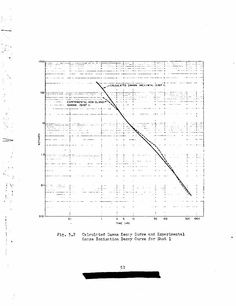
.----
i..
.
.. . .
“..,.
.,
., .
r..,
. ‘1!.
I
I
i
I
F’-–— – -+---––-----—-–*--—-----—--- --– -– .—-—.—--—-—-—- -—---. ---{
}---” “- . .-—. +---- ..–. .–. II I l,, (
001 .-J —01 I 35 IG
TIME (HRI
Fig. 5.2 Cglculzted Gama Eec~.yCurveGsnna Ionizct.ionDecay Curve
50 100 50G 000
cnd Experimentalfor Shot 1

.
1
I. .
L’ --’,.
.:
..-,
!,..;”
\ ‘:.
,’
.-
. . . .!
,
...-.-.. ,-- .:
. .
scakterin~,and absorption do not affect tbe detector res~mse or ganmaspctrm seen by the det~ctor. Si3ce the latter cotiiitionis never fullysatisfied, the calculated curve always di!’fersfrom the exFerimentolone.Table 5ol-tabu~3testhe slopes of the theoreticaldecay CuX’ve3considered*
The experimentalbeta decay curve for Shot 4 (Fig. 5.1) and the experi-mental gamma ionizationc?ecaycurve (Fir. 5.2) for Shot 1 are presentedfor comparison. The two theoreticalbeta decflycurves are in very closeagrcemnt And each arree well with the experimentalbeta tiecaycurve.Th~ experimental ~armm ionizationdecay cume for Shot 1 rindthe cal-culated gamma (lJev/min)decay curve (Fir. 5.2) ere not in cood fi~reementfrom 5 to 100 hr after detonation. This lnck o? a~reement may ke due tothe nature of the response of the i~nization instru~entor to other fsctars.
TM3LE 5.1 - TheoreticalDecay Deta1
Type of Decay
Calculated Rammaionizationdecay --Shot 1 (Mev/min)
Calculated betadecay -- Jhot 1 (d/m)
Calculated betaSecay -- Kike “Shot,1V% (d/m)— —. —
Slope of Decay Curve oier Period Indicated(hr after ABD)
1- 3 1-5 3-M 5-96 \2L-- 1440 96- 672—.
1.37i1.08i 1.33I
,
~!
4
I
1 ..L2 0.83 ~ 1./+O ~1
1.44 0.g65 1.37I
I i’FiWre ?.3 is a composite camma ionizationdec~y curve con-
structed from all avcilable field data; it has been used in this reno~for conversionof ell field data taken with anAK/PDR-TIB, AN/?DR/39,or the gemma ionizathn time-intensityrecorders as well as for conver-sion of the 477gamma ionizat~.onchamber laborato~ data. Com,%risonof How Island Task Force F??ciSafe measurements snd the Project 2.5sgamma time-intensitymeasurements shows very close Qgreement !kon O + 2to O+ 20days after Shot 1 (Table 5.2).
This agreement of the time-intensityrocoxder curve with fieldsurvey readirqs was assumed to hold between O + 2 hr and O + 2 days.Therefore, for the time interval (O + 3 hr to O + 20 dayu) the time-intensity recorderdata were used to construct the commsite cllrve(Fig. 5.3). However, for the lntenal from O + 1 hr to O + 3 hr thegamma i.ime-intensityrecorder must be compensatedfor fallout that wasstill arrivi;~? the compensated curve would then heve a slope steenerthan the experime~’‘1 decay cu~e. For this interval (O + 1 hr toO + 3 hr) the calculate ;“mm decay curve was used in t’.;econstructionof this composite decay curve.
53
\

.
,
.
. .
.,!,-,., .
--\
.
,.
,. .
I.0
0.10
>t-2001‘v4P
,“....... . . ,.
‘—
0.001
\,.
,
.
-. .
/
I
~
I
[
11
I
J—
I f----- —
[
I w—.I II
I 10 100 500TIME(Hi?)
FiE. 5.3 Composite Gaxna IonizationDecay Curve
5L
I
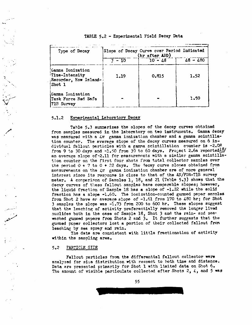
..-”%.
,... ~... . . .
<~.,.-. .
>...
‘..... -,
.
-------.,
.
Tnw 5.2 - ExperimentalField Decay Data
......——~$~~i-Dec;Y---]__lol~-~
(iii~~i~:,..,,.,-zg;
Slope of Decay Curve over Period Indicated
I I‘GammaIonization~Time-Intensity 1019 0.815 1.52‘Recorder,How Island-jIIShot 1
Gamma IonizationTask Force Rad Safe
1- J-’
1.50TIB SUrvoy——.— ...——.-.——— .—— —..—
5.1.2 E~rimenta~ ~horato ry Deca~
Table 5.3 summarizes the slopes of the decay curves obtainedfrom samples measured in the laboratory on two inatmnents. Gma decaywas measured with a Lm gamma imization chamber and a gamma scintilla-tion counter. The average slope of the decay curves measured on 6 in-dividual fallout particles with a gamma scintillation counter is -2.!)8from 9 to 30 days and -1.50 from 3C)to 60 days. Pro;ect 2.6a reportewan avera~e slope of-2.11 for measurementswith a similar gamma scintilla-tion counter on the first four shots from total collector samples overthe period O + 7 to O + 22 dnys, The 3ecay curve slopes obtainal frommeasurements on the @ gamma ionization chamber are of more generalinterest since its response is close to thatof the AN/PDR-TIB suveymeter. A conprison of Samles 1, 18, ati 21 (Teble 5.3) shows that tiedecay curves of t!:esefallout samples have comparable slopes; however,the liquid fmction ofSa@e 18 has a slope of -1.22 while the solidfraction has a slope -1.60. The ionization-countedgummed paper samplesfrom Shot 2 have er average slope of -1.61 from 170 to 480 hr; for Shot3 samples the slope was -1.73 from 200 to 600 hr. These slopes suggestthat the Ieachlnq of activity preferentiallyremoved the longer livednuclides both in the case of Sample 18, Shot 3 and the rain- and sea-washed gummed pspers from Shots 2 and 3. It further suggests that thegummed ~per collectors lost a portion of their collected fallout fromleaching by sea spiny and rain.
The data are consistent with little fractionationof activitywithin the samplhg area.
5.2 FARTICLE SIZE
Fallout particles fhm the dtffarential fallout collector wereanalyzed for size distributionwith res~ct to hth time and distance.Data are presented primarily for Shot 1 with limited data on Shot 6.The amount of visib~e particulatecollectwl after Shots 2, 4, and 5 was
55

L
~
4*—--- ... .- ______ ._
.— . . ..- —-—
T
-—-
--- Ig 0
1+ I
1
+*..-—,-
.:.. . do.-.-—A 3-4—. ------- —. -—.-— ..— -.
0m+“
——-—- .-—---- .-%r-l—-.—— _ _.._ ..._. . .
t
.,,’ ?iJ 1- -. .
1+-— -- . ..-———
-N
--———
.— .-. -—. - .—-i
----..-—
+
0m:
.- .-. ...—. . ..
. ..— ~,
_— _- ------ . .. .
——- -—.—. .-— —.
---- —
.:
“. ,‘b ,,
.\ L..—I.—1‘.
. .-— -- —-——
n
\
.
-.
,-.
.:
m CO*
i.r)) .— —-. —

— ——
8Am@r+
. . .
..n
I
I
1r
1I
.1... ,.
.’. .iI
.—. —. I
$
H
w
Nml40G
Q.8u)
C&d0“InN
I0riC&
1G.-
..-. ——. — — .. . —..- ..- ——-
——. .. . . . .
57

‘1
II,’
,,,.’,
-.....-. —
00!32 3
,!:,,0
20C’V4J 3‘\,
—..
,,. .
.,
<’-”’,,;-.“
, .-u
.. . ..20d
o*LnN
6-
!2E+ r
—..—I
,’,.,. ——------4.... 1,,..
“ “..!
,,
.*
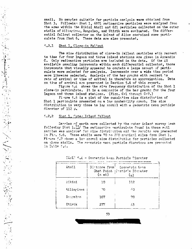
,,‘<’
.<,-
,..,..1
,----
. .
.. .!
‘v“<-..\..
(.
.)1’
1_,.;....;-.5$i)”-.
1-
;r-.;..-.
I ,, -.
. .“.. .
+’....,.. ,
.,,.. .
“b,-,}-\.,, ,.-
\ ,..,
.. . .:- .,
\ ,.,./
,) ~..
.’
r. .“. .
sm~ll● No sampSe3 suitable for pafi.ic~eanolysls were o%tatnec?fromSh~t 3. Fcllowin: Shot 1, 6971 radioactiveprtlcles were analyzed from #tbe @rea within the Bikini Atcll and 621 prticles collected on the outeratolls of Ailin[!inae,Rongelaa,and Utirlk were eveluated. The differ-ential failouf collector on the island of Alice contsined some arti-culate from Shot 6. These data are alao presented.
5.2.1 Shot 1. Clnse-in Fallout
The size distributionof close-in fallout particles wf.thresnectto the for four hgcwn end thrje island stations are civen in Appendixc. Only radioactivepert,iclesare included in the deta. Of the 40amilable sampling incrementswithin each differentialcollector thoseincrecientsthat visually appeared to contain a large ammnt of prti-cuiate were selected for analysis. Increments over a wide time periodwere likewise selected. ArAlysis of the bar grnphs with respect 4.0rate of arrival or the of arrival is therefore nn apyroximtion. Dataon time of arrival are presented in Section 5.6 of th~s re?ort.
Fig:ro 5.L shows the Z?7S frequencydistribu+.ionof tho Sh~t 1close-in particulate. It is a con::ositeof the bar granhc for tho fourlagoon nnd three island stations. (FiPs. C-1 throu~h C-7.)
Fi.nme 5.5 is a plot of the cumul::t,ivesize distril:$~+ionofShot 1 priiculate prasented en a lop probabilityCrenh. The sizedistribution is very close to log nomal with u Ceometricr;ean~rticlecli~r,eterQf 112 i-%
5.2.2 SY!ot1. cuter Is191Yl ?allout
Sa~ple3 nf earth were collected by the outer island survey :eamfollowir~S~iot1.13 ‘i’herqdioac+,ivemrticul%to found in thess scilJsan~les was analyze? ?OY size 5istr3.!‘~ticmnn! ‘he re?ults are ?reseztedjn M;*. 5.6. These atolls were 7cI to 2?0 n~ut,ic~imiles fron Shot 1.Fimre !.7 showr a Ion ng.mal size cljstributivn~or ~ti,icles collected
TAsL? ~.L - Geonetric h.-a;;PtirticleI’iar.eter~=—— .-—.—.....—. ..—-.—--——- .---— . ..——. ......_---—–l——————————————_-~–_—.— .-
I j_ (.mi) I - (Y)1
——- - II 1 —!
?0
107 :I
1 I I
L___”!::k___j--- 2n_~ /;?---- .-._--.!
..’
. !!,.’ ~-
‘ ,.,!
,
.,.,,.1,
59

—.— __ .——.———
----
i
i
r
.. /. ..
— .- _-—. —
. . . . . .. . .. . . . . :.::: . ...:. . . . . . . . . . . . . . .. . . . . . . . . . . . . .. . . . . . . . . . . . . .. . . . . . . . . . . .x . . . . . . . . . . . .!-.
,.:
~;: :600000000000 .
u.<, ~,nonnooooo 0000
s!! NKl_. r.N.o*.o &?- am–oIlltlll!tillt 10
0? Of–––– –-----– --=~ m,.>~,.n,,l.)[>.! .->o OOOA
d- -—r,ru..~.nd Amm
m I
o0(w
o
00.0
0
zouo
w
..-4
-

—_— -. .———.
-.,
-.
/!
i
. . . . . . . . . —,,
:1
1:,
o’m.m.*n*- rd o**.mm*-0 0
.
n
mm
<$6
z
L:w-l
L-
wn
Q
.-!
0
N
/--
jccl
,>0xm
GG
.-
-.
.,
61

.—— —
,,
,,\..
●✌✎✎
J.,
i.!.
L. .
/-,’-- 1
o0r-i
o0CJ
o0
0
?
o0m
~
o0—
o
...
,, .
.)>“./,,. .
/
——. —.— m.— -——
. ../>
/
o,.“/f;“/
>’ V-J
)=2ut-d n
“\.,-
,.. ,r
—.-— .–—-—.———————I .0ml
o“
./‘,..
2<
I_ ,
.
-“..-
.

. ..,.-
...
-----I
/“’.
—. -...—————— —.
? 1 ,:
/!: I,! : , ~ 1’
~[ ~
:- 4 ---- . --; .6- —-----
+--—-——— .
1:;+. _*. ._A. -- —.
-— -— —--——— - -——
. ..— — .. —_ ——___ ___
. .——
-——.
L . ~+. — _
U.
— -—-.. ——-—. - J—.
——~ —.
+ . . .–—. — . -.. .-.+.. -—, ——.-—- .—---- a-
ll IIi 1
● -,-..-- -—–. . .
T-—-—-— ---. - .+–.-–—-,-—-—-—-—---I I
,,L+__.. - _+—. L—– ____ – —..—-
. .
. . .
.+- *
(
- . .
. .
. .
I+7
111:
~
1
t
+
.
.
,
,
I
i
I
.
.
-.
.
+
,
i‘1
. . .
f ‘-.———-—
\o
-– –.. b .. .... .
,.. . . . . .
--------- ---–-——
+..
.+. ; .,i
.-’. . . .I ] ; ‘“I I
$-ZLuv
awa
i5 =(S NO M31W) U313WVI0 3191 iMVd
., -,,
,“
, /
---..
../=’.,
,.,
,+
.-.. .
;
..-
63
.-

.
,- .,
.-.
“.,,
J’ ‘,. . .
t,/
,’
. .-. .
-.,.,
—.
,, --,,.
,. ,. -
The fact that the meon particle diameter at Ailippinbeis smaller thanet Ronge16p cen be partially explained by enalysis of the wind profilewhich indicates,as one moves south from the BX3S of s~”etzy of thefrllout ptterntthat,the particlesdelivered have smaller diamete]s (seeChapter 6).
5.2.? Shot 6. particle Si7>o.—.
The differential collector st~+tionedon Alice contnined visiljle-.:
Partict.llat.ens well as sone liquid.;ttieanalysic of pnrticle size dis-tribution 1s presented in APnendix C. with a tOtfil Of 321 particlesmeasured the distributiontie nearly 10C normal withdiamet,erof 180 p &s shown in Fig. 5.8. Alice WS 3from ~round zero.
5.3 WTIO OF ACTIVE TO INACTIVE PARTICIJ!S
a geometricmeannauticalmiles
One of the most difficult problems to resolve is the ratio ofactive to inactive fallout p~rticles that arrive at a collectin~ instru-ment. This is especially true of the smeller diameter particles becauseit is extremely dit’ricultto avoid pollution of the sample hy extraneousparticulate. In this anelysis many smll i.n~ctiveparticles were observedduri~ the measurement of particle diameters. Yn many crisesthese Parti-cles were less than 5 P in dlmeter. To arrive nt 3 ratio, all p~rti-culate was ignored that did not have tie cha~cteristic White owq~ecolor of fallout.
TJ70samples were analyzed from Shot 1 fallout collected at lagoonstations where the effect of islnnd.dust pollutionwas minti.ized. Theresults are shovn in Fig. 5.9. Apwroxirmtely 25 per cent of the partl-C1OS were fonnd to be inective with the mean prticle size of the in-active particles smeller then the active.
5.4 ?ARTICIZPE!31TY
‘.I
.,,.,-.’
. . ..,./
,..,.
i‘, ,;
,.”
Particles from the Shot 1 lagcon station differential falloutcollectors were analyzed to determine their appnrent density which isdefined as the specific gravity of the particle as a whole. Because ofthe station locations and the collectir~;;instrumentused, these Particleaha~ a very high probability of being trtiefallout. Seventy-qin.eF~rticlesfrom stations 250.04, 250.17, end 250.?h were measured. Densityp averaqediameter, color, and relative activity were determined for each particle.
Table 5.5 sbcvs the prticlc density found at each station. Theoverall averfiqedensitJ of the 79 particles was 2.36 g/cu cm with astandafi deviation of 8.9 per cent.
Attempts to find relationshipsbetween particle size and activity;particlo size and density; and density nnd activity proved unsucce~stil.All particle density data are tabulnted Sn AppenciixD.
‘. ,
/
..--.
.
.,
-..“
...“
.,.
.-
-,..>‘
.-.
....
.:/- .-,./. . .
.J.
..

/...
/.
m11 1
mmI II 1; ~i!,’( l!,
I: 1 !. !- :--! -.----j ‘---–—’-”- ;-— . .
1 ~m. mO
0
1 I I!,
.-.
b.. .
!,
. .. ..-_... r-- . “
+ —.
:---\--–-flu7-j...._! :
.>,.
,7,-. . ,,’
.:,7- –.., . ... ..
:, ;---__: ----
IQ,L.L. .
. . . . .. . . . . .-——-- --—+
-+.-+–,. .. --—----
. . ~ L___..... _–_..--.-.-.ab---
~ :“----m
. . mm
i ‘-----—-–- ~
. .
b–. . .. .4.:. I ,
.-
.-
.. .
- —.
‘._...-
,..,“
..-.“”.-+..
1. -- —?——-- — - ———— --1~.
i L....-——u1-
\ _. L..-–.–_.....+.....-4-.+-:... +–-.,! ~w
.=I“’ i’_ -
:“- i4
t . ‘ . “ ‘ ‘ “- : “ ‘“”-”--–:”--–-””---–$:;~- —. . . . . -.--.—-..- -- —-— s?
4 ~ ;~\:_____ . , :....._:.. ● ; , ..-..-_-–.– ~;w
~ \Jc!
; 1“--:
\- - ..:.~-+---- -----~-....–; ---—---~;
\’ ,
Y
<,:. . 4 - -- --+---,-----!---”+-” ‘“ ...——...–— ‘w
;, , ‘ :
1‘\ 1 :4. :V.’:;”--’
gtl“”-; !, r
_-.-———-.—
\i~__,,\~,– t ; ““- , ; ‘-> ; ‘~”--:”--—;–-——--- “0
!1 I
,1
‘ ‘t’
~_.__..,._.._ . . . ,. + ~.~.._7.. K-L... ~...—.-–--w
~~ .~~!i ].. L\___ ‘-
!1 [
i I ~- f- --..+------- ‘-:.-+---— —- ?--- -----td,
—+——T
..+— ———— —t_______
o-;--t..!. - :--: ----- —,;
L___ i I ~ I J_.__j__——+ -....——~— +.—---.--A- ———. ;–+.--;--:- .—-..,,, :,: ‘“-’----l-._..i.~./.l/.~--i....-! ..-T_______ .:
Illlil
J._w! ‘----i ‘“ 11 ! 11.1 1 L_.-.] j
mm -au-u v, r+ Oma.<..$-l N
o
>.
..-L-._...-_
.
..*. –.——-.—–
.
,, .
‘-.. ....
.-
.4
--.-
..-,
i~,,.,.-,-..
‘I+j!:... \.,, +
. . ,,., -.,,..
I
,!-.+
;1
,.. .:
. .
...-
. -.,:,..’
.65
..-.
--. ..>

—..—
I .-
---
-’. ..
/’;.,..
--.-’,
.’.:
..,. .:.
i ““1.
., ..-
:<.’:....“_;
y<.,.
,.i.
..’.,.
/- .- -..
. .,.:
. ..
:>-. :... .
..,.
.../’./,,
,,:.,,.---
,,\....,-, ‘i
160
140
;20u?LJ~ 100
G~ 80&
~—————————————— 7
STATION 25006
at 0+30 MIN IL
DIA!4ETER (MICRONS)
40~.~ —
STATION 2500401 0+90 MIN
~ ACTIVEg INAf,TIVE
TOTAL NOOF PARTICLES-222
INACTIVE’68% INACTIVE’31
DIAMETER (MICRONS)
Fig. 5.9 Shot 1, Ratio of Active to InactiveP&rtlcles
.,/;“.-....
/-’
‘. ~
-’..:i
. .,-..
-.
-,
,... .
66
..<;...

TABLE5.5 - Particle De~sity——- .-——--.——-— —.—--.-— --——---—— —-. — —./—
__..
‘---1”-”-””
——. -.-......... ... .
I
11!0. of Ferticles AveraRe Standard
i Station Inv~2stig~ted Density Ueviation
—— -----——-. —-——
Iaz::]:Y(”e:::.
5.5 cROSS F!!Y51CAL C!!AMCTW.IUTICS OF FAIMNT
Comrweherlsivedate OIiph,ysicaland chemical characteristicsoffallout are preseriteclI.Lthe Project 2.6a re?ort.~g’?
5.5.1 Surface Land Shots
It is well establishedthat the fallouj from the island shotswas very simi~ar to that which occurred after Mike shot t?tI~f,LMmely~ry, white, opaque, irre~~lfirlyshaped particles. Figure 5.10 showsShot 1 fallout 89 it arrived on ‘:hegwzned pnper collector loceted atstation 250.04. It is ty-oicalof fallout f’romI.slcr.ddetonations inthe Pacific Provi~ Ground.
5.5.2 SllrfaceNater Shots
positive evidence of prticuht,e fal]Gutwas found in tke dif-ferential collector lC,cKtedat Alice 151~zd a;’t.erShot 6. However, the
Summed psper col:ectcrs loc8ted on the free fioatin~ buoys after Shot 2shoved no evidenco cf ar.ypsrticlesvisil)leto the naked eye. It isfelt Fy some otservers that the fallout...4..omthe surface wp{”erdet,0rlJ3-
t.ionswas primarily in the form of ~ mitt or aerocol. This is su~~~tnn-tiated to so~e degree by the observ~tionof the i6eritificet.ionflagslocated on the sea stationg after Shot 2.. These flags were hi~~hlyradioactive,r.enytines more ac+,ivothn the total collcc?ors of thesane station. It is reacona!le to assmn- thet a moist fire fnl.loutwould ke ~b~or}d }Jy ?he fleppi~ flegs much moTcee~sily t!:finrould ndry portlculate.
5.6 TIN% OF ARRIVAL 0? FALLCUT
The primary instnment for deternlnifi~the mricd over ‘whichfeli-out took piece was the differenf,ialfallcut collector. ~nf~~at,jonon
time of arrivsl wes RISO obtejne? from the ~anm time-intensityrecorderst~tioned on How Islcncl;further in!”o:m~tionmy ?-eobtained from the-intensity recorders oneratetiby Prco.ject2.2. Also,limited evidence ofarrival tire is uvailnlJlefrom ~h~ Ta9k $’orceShip~s logs and ProJect 6.L.
67

.——— —-—- ———”’” ..——-— —.:
:..,\ ...,. \.>+.
f‘.
. .,- .. J...A .
. . .,-:..
‘---.;,.,.
‘.- ..’.-,/.._.
.-’. -..,.s:’
F :’ .!.
.... . . .. .I--
--- >+-- .:
..I-~h,.,/’ &y.
..-. !,. .
,-. , ..>.
.,
a,.7, ,,. . .. .yi!,
-+’+.,,)..:..-..-..-./’
...\.--:>:,. ..,’,. ,,..-. . .. .
\-..~;’:‘.
\.\\ ,. . / ..:,.,.
I;J./,: ...
//,/.,/ 4
‘>/-”i.
,’ --
●
WI
..- ,.
,.,~

...,,.,1
“h!.:’...’\
\,, ...
/‘
---:
\ ..
,,./’:,-
,...,’
‘.:
--%.. .
.,
‘/
,!”/’
pol,r~een al: ... . . .. . ..~p ,1fallout collectorswere recovered frcmthe 1ZE4 ar.dlagoon st~’.inr~~fter Shot I* Of these, ei~ht ‘t:.tiscnnledpr:rerl.verd the tiat.athere~rm ?re presented in Anpendix C (Fk~. C-”t~rc~h C-16). of the LO ga:~l~::j-increments,Samples 10 nnd 11, 20
and 21, afid30 an2 31 mere collecte< over the same time intervnl (seemints A,B, acd C of Figs. C-” t.hrourhC-16*) ~ith perfect s~PliWthese increments would collect i?cntic:jlamounts of fallout and thereduced c!atacould then be used tn determine not only the period offallout hut also ‘he rate of orti.:sl. However, LS indicat~~ fromincrtr-~ntgroups A,B, and C, the levels of activity varied b7 as much n-nn order of ma~nitude. This vari.~tionwas undoubtedly the remilt ofsampling small emounts of meterial over a small area ior short time‘c%en-8?c. ‘Ms Deficiency does not affect the usefulness of the i..-trunent ir]perfo~ing its primery function of detemini~ the time ofarriv~l but it does exDlain the ~rratic nfitureof the curves. RelativeCCUC?S of each Increnent were rwde “S:j.the ganma scintillationcounterunc?erfixed Reometry. ‘Theleve~ )? activity es inc?icateclin Figs. C-?thrcmph c-16 should not he constrwd as indicativeof the rate of arrivalof fallout meterialo
Several differential fallout,collectors that failed to triggerwere analyzed to determine the !leld backrfiumd of the collecting in-crements. Firue c-17 shows the ~ener~l level of contamine.tionfo~d in
a non-c~erati~ sampler located at statfon 251.09 that was exposed tofallout.
Table 5.6 tabuletes time of arriv~ilpericd and time of cessa-tion of fallout within the 3ikini Atoll ares. Dat~ collected from Proj-ect 2.2 Bnd Pro~ect 2.5a tiine-in+,ensi+yrecolder tmces are also pre-sected.
TA::IX5.6 - Time of Arrival of Fallout~. -——.——- - .-. .— -—— _.r T.-.T.._-—- .—
The of
I Stntion sam~ler lArrivai ~ Period
r— — .—-1 250.C5~ 250~
I 250:22\ 250.2.
251,0L251.05251.06251.10251.C3
\ Dog, oboe
+
(rein) (rein)— . ——. .. .—
Differential Collector : 0 + 20 125Difi’e%ntial Collector’Differential CollectorDifferential CollectorDifferential ColloctorDifferential CollectorDifferential CollectorDifferentialCollector~lqe Intensity Recorderl
0+25 1150+35 i 600+25 ! 80c)+~o ~ 1250+35 900+25 ; 700+40 50C+15 ; -
~a~Proj. 2*2 <0 + 15 1-Proj. 2.2 <()+ 15
i-
(a) See:.eference 2foranaccoutof this project
~
—
Time ofCessation
(rein)
O+U5O+IAO(3+950+95o + 1550 + 1250+950+90
.

,“..’.,.
-. ;-.
,’
.“.‘..
,/>.
/,-.
.. .. . . ..
-. ,
- .,..
Analysis of the gamma time-intensity recordor trace located at How gavethe best evidence of the rate of arrival or fallout.
..
Use of the differential fallout collector end the time-intensityrecorder for determining the ~riod of fallout was restricted to theIaFoon nnd islands of Bikini Atoll thereby limiting the distance to 15nauticel miles. The average arrivel the within the area was O + 28 minwith cessation awemgi~ O + 117 mln resulting in an avers e period of~ min. VY$These data compare well wtth that observed at I ~lwher- theperiod was somewhat less than 2 hr. Resid*ualfallout which was of suchquantity thet.it cmtributed little to the overall field was found todepc)sitfor a ~ricd of several hours after the depoiJitionof tie mainbody of materiel.
The Bikini Atoll islands along the axis of the fallout pattqrnexperienced fallcut over a longer period of time than did those islatislocnted in a crosswise direction.
5.6.2 shot 2
No evidence was found of primary fallout at early times in theBikini Lagoon. Secondary fallout of maximum intensity of 40 mr/hrarrived at How Island 37.5 hr after sh.~ 2? as shown ~ the g-a ‘tie-intensity recotiero
5*6.3 Shot ~
No differexti.alfallout collectors were operative for Shot 3.The gacmm time-intensityrecofier at How Island indicated a time of’ar~val of o + 38 min. Project 2.2 established an arrival the onDoSIslNnd of approximatelyO + 20rnin.y
shot 65.6.L
One differential fallou~ collector located ~t Alice Is13d$~n~xetok Atoll, received significant fallout and inc?ica!cdan arrivalthe of O + 35 min with the period of fallout heinp 65 mir.(Fig. c-18).
Of the two gamma ionization time-intensityrecoxders installedon Yoke and How Islands of ~ikini Atoll, only the one on How survivedEnd recoxxladdata from Shots 1, 2, an+ 30 These dcta give accurateinffomation cn rate of arrivel of fallout “1.3well as time of arrivaie
5.7.1 Rate of Arrival
..ah]e <.’7~res~nt,sthe time of arrival of fallOUt end time of-.peak aci-.ivity‘or Shots 1, ~, and 3. The time at which the activitypeak- is not the time of cessation of fallout. It is best desctibed as:he time at which *?e rate of decay is greater thm the rate of build-up of fallout.
’70
,
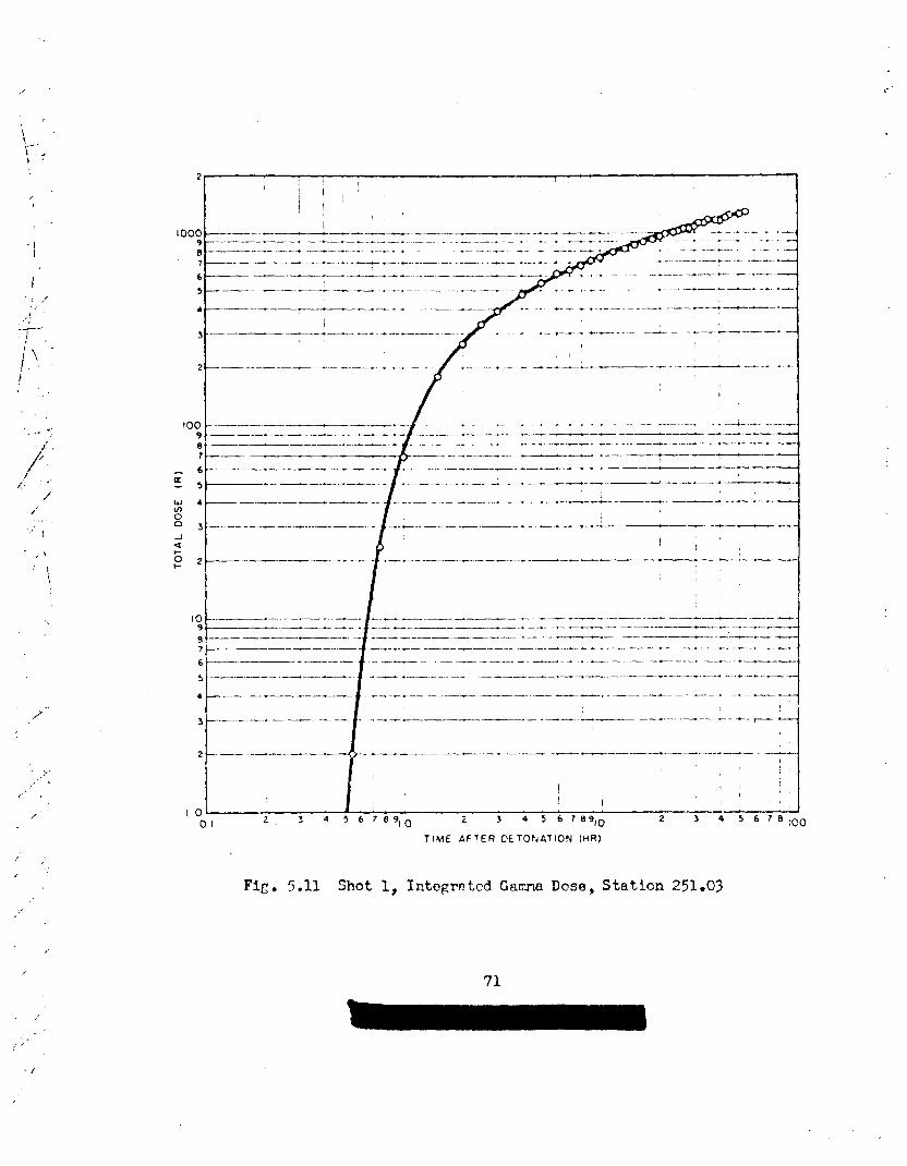
<“
, ,/.,
,!
—-.!.
(~. :t
/’.;”
1
./“
<“ ,
/
,,
,
?
I000987
6
5
4
3
2
10091871
6a
5;
W4VIon,
da
Z2+
109
.9?
6
5
4
3
2
10
, I( Ii I
_ ... ___ —.x -+
I
/
-.—- _—— . . . . . . . ... ——. _- ._. -——-—. .-+.——— -—
_ . ~.- -—. —. .. . . . --.———. —.. . . ..+—. . +- —-- — ——— ——-. -— ——- .-
[
!
,,
—— --- ——. .—— —.. . . . . ..— —. . . . . - -- -.—.-—-.—— -— --- —-— -- - -
.—— —.—. —
E-.—.—.. ... —------.—––—--..—.—..............----— —.—.-.. —.—.. -—-—————.——————-.—-—. --—-.-.--——-—..—.—-..—.--——-—— --–—
—— —— i5-—.- -___—--.—-—— .—.———— —.. ——. — —.. .. . - J— - –—--—-—. ---- — ..— .— .-- —— -----——
/
—.— ——. .-——.-. . . -—— .—--.--— — .——— —. —.. —.—.. -+.,——. .— —.—-———— -— . .——-—.—-..— — . ... --..——— .- -————+——— —-. —
—-–—-—-–- J --”---— ---— —–------—-”” -———--”–— —
/
I,,,
——— —---- . . .—. .—— -—..—— . ..— — -z .——-— :-. — --
....— ..—
/
—-- —.——. ————. -—-. ----. ——. .—— .——.— .——#—..— —.- —. - -... -.—— _ -— --—-.. -.—-—— — —— -.. ——. .- .-—. —
——— ————.-.. -- -—---—— ..—.————--- - .—— —-—-——— —..”-—.————— ——. -—-...— .. ....—. —- _ —.--— ___-.— --.—-——. - -— -.. —
‘--—-–--– f ‘“”‘--- “-“‘--” ‘--”’”“ ‘---’-’ – ‘----”-----””----”’-—-–i.——..-.-.—-.. —-.—. -— .— .——.. .—--- —- ——-—.—.—. —.——.—.——- .. -—. ---- —---- -
—-.—. 1’—.————.--..—..—..—-———–-————..—————-—-——--—-.+..--——I
—— .—-. ..— ~ .— --- -—-— ——. - ——. — ..4-... –— ——. — ———.——- .--.-+. * -
—————
/
.- —— —.. ——..—- .—~ ..— .———.. — —-— -_. ._ -_ —.I
{ ,1,,, ,
1,
I2 34 56789,0 i
01 3 4 5 67t3910 z 34 5678;00
TIME AFTER CETOPJATION IHR)
Fig. 5.11 Shot 1, IRtegretedGwrm Dose, Station 251.03,.
,.
71
,/,.-
; ;’
,/

,/
, ..,1
I
.,I
/1‘...
.( ‘.
z-..,,/.,,/’
/./’. . ...’.
./. .!
/.
,,../.’
,.-
,/ .‘,,,/’ ,,.
>/.. .,..f
,’
‘..,.
. ,.,, ,
,/
,,, ”
./
,.-/
-’ ----
,/’,/..
. . .,/” ,
,’
o
TIME AFTER DETONATION [HR)
.’
/-/
/’
/
*
Fig. 5.12 Shot 3, IntegratedGamma Dose, Station 251.03
72
.,,,,
,.’
,“-,/
,.,/... -’ 4
,,(

,.. -
,/”,,
/
8/“..
,“.P
.,, ‘.’
,’”/?./:. -
.<,,’/.//
/-“,,
.“’.-/ . .
/,,‘,
.-.,/
TABLE 5.7 - Rate of Arrivalof Fallatt—-.— —----. ..-— —
Shot Station
1 How Island
3: How Island
2 HOW IslandSoconda.y”fallout) A
The r)f ‘lime:9 Peak Time Between FalloutArrival
IActivity Arfivnl and Peak
(rein) (rein) Activity(rein) “
0+15 ()+65 50
(’)+3$ (3+6(5 28
()+ 2250 o+ 3280 1030
5.7.2 Total Dose
Fitzures5.11 and 5.12 indicate the inteh.ated ganma dose to a“.
time approximately-lOOhr after detonation for Sh~ts 1 a~ 3. Shot 2deposited only socorxlary fallout on How Island and the data are notpresented.
i“
//.
f./
/’”
.’
/,
73,-’.
,,.. ,
;“/’.
/’;.
,,./

PRIMARY FALLOUT PATTERNS
The extent of fallout documentationu(.derthe two o~er~:ionalphases of fioject 2.5a kas different for the various shots. Data wereobttined under the lad and lagoon phase for S:lotsls3~4~ ~d 6. TheLgoon and islands were not contamin:.tedafter Shot 2 and no data weretaken for Shot 5. Although there was some stem fallout west of the snobpoint as indicbted by tb~ trajectory analysis yrecented ir. Section 5.5Ythe free.flo~ti~ sea stations fc~Shot 1 &ere 1:.idjuzt beyond tnewestward l~~it of the gsrcnafield, Concemcntly the b!loysshowd thatinappreciablee-nountsof a~teri~l fron Snot 1 fell in the area sanvlcd.?or Shot 2, free-floatin~stations documented fallout to a distariceof50 nautical nile~o
A cortpleteanalysis of the fsllout patterns to a distance of 300nautical WCS is presented for S:lot1. Becauso of the lhited experi-mental data availuble for this Shot it was not pozsi:le to reconstructthe contours on tnis basis alone. ~hc ,c-- field data were su~ple-mented by develo~i~q an e~erimental model Or t:~e f~lout mechanisnwhiC~abled
pling
4.1
basic
defined the as of symmetry of tne pattern. l’nisaddition en-one to construct a co’~pletecontour pattern,Fallout patterns for Shots 5 and 6 were derived from wcter sam-data and are considered in Reject 2.7.~
‘ioobtain the infinite field ga--malevels within the atolls, tnreecollecting devices were rlaced on the isl:’.ndsand on the rafts
within tine lago& as follows: -
(a) Total collector - a 7-iE. dieneter pclyetnylenefunnelfitted to a l-gal polyethylenebottle.
(b) Gummed paper collector - 1 sq ft of Xum-.Qeen ecetete-backetipaper stapled to a cardboard backinp .wpported in n ~t~ tr~.
(c) Project 2.1 fih badges placed tot!~vertically and horizon-tally.
~ co=rpnxingthe IaborattizyaeFt’,urecl levels of ~anmaactlhdty ob-ttined from sanples that vere collected on islunds with the actual in-ficit+ field gamma survey readings, a relztio~hi~ was developed and
74
,/”’
,,.-
,
.-0
-,
.,
;.
,-..
●
..
./,
.’
.. .
.._
.,.-‘>
., . ..,..- >...

...
/’
.+--
,..-~./
r~plied to the san-les collected at the lagoon stations, tnereby per-n.ittinqcstim:~tior.of infinite field levels for those lorations. Uzingthe tot~ collector n.s the prin~y souce of data, Cama field contoursTO:ereth~~ ~on~~~~ted. f~~re tot~ collector data vere mfssin~, CICtfV-ity levels obtain~d fron t!legunned ya~r collectorswere usedo aldata Frcsented are lxx”><?on tie levels o? acti-.ityth-.twould haveexisted h:.dthe fallrut deposited on cn infiniteland plcneo
‘J’h9fieldz as indicatedCy the f.ilnha:~es were erratic. % causeof poor location 0? tiw film badges duri~~ Smplinc ti?Ad unsatisfactoryhistory durir.qan:ltiter recovery, these data arc not considered inthis analysis.
6.1.1 shot Y.—.
.....
,/
i
,,
.,’‘ /,’
.. ../
/i. .
:.\ ““,; -
.-.
,.,
,/’.. .
—.————.
Stztion
.—.—. ..—.
251.0.22!a.03251.9/.251.05
— —————...—..—
1—————-..----—---——-—
1:ode
?.!cacuredby , ~’e~~uredby] Rad Safe Proj. 2.5Q
.._ .--.—--A- .-----— ------ -- ..—.-
~o~ 1920 1 1390.;Ow 510 600Love I
I &270 i
!{an I 213251.& , C>oe ! TA
251.0? ~ ~?n~~e \ 25
251.08 1 Wil.licm~ 21251.09 Yoke251.10
I ;8Zebra
250.CV. ‘ Laqoon ! -253,05 L2goon , -250.f% Lgoon ~ -253.17 L~~@on ~ -259.18 L~oon !
ILCGoon
!?+Lagoon
i-.
.___._ l-._2—
208.(51717
21
. ——.——
TotelCo~ector~fi~~ is.....- .——
1630725
:;;51l:?23
23113
I 68
.:-L.
-9.[b7.520
—.——
75
GummedPaper }Ard.ysis.—..—.— 4
I528
I3126
.-
1128660
50
~J
,,
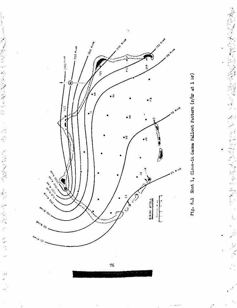
\
..
<...
. ‘<
-... ..
,,... .
.’..-
.,”
./- .-:.../
...-...-./
. . .
.-.- .\
,.
....-. .
%_
b
●
●
●
/
*
.
,
..
-i, .
,>. .. ... ,---
}. .-V.,. ...’”’ .’.Z
\ . ...-..-.-1---i
./ Js
.<.,
/,,. .
//-
.!. .
.,
/. ..<
-.. ...r
~.-. .
../.“
-. .-,
. .. /“
,..“---
<’
76
-,,’
t’
.

....-,--,.
.,”’
601.2 Shot 3
“..“ TheShot 3 pattern was well defined because the direction* of/,, fallout crossed the collcctin: array ~erfectly. The highest measured.-level of gamma activity was 360 r/hr at 1 hr at Station 250.17 (see‘(. Table 6.2). FiUgure6.2 presents the gamma fallout pattern in r/hr at--1 hr.-///
../
1’/-, ‘i’JM.E 6.2 - Shot 3, Gmma Infinite Field ~ve]s at ~ik~ni ~toll Convertedfi-,.. to r/hr at 1 hr as Determined by Various Techniques;~,,
r~ ~~
—.- — ~– -2
,,
t.,,‘:,.;.
, ,;
IIStation Code
251.02 Tox251.03 Jow251.04 Love251.08 Liuiar!l251.10 Zebra250.01 Lagoon25C.02 Lagoon250.05 Lagoon25C.05 Iagoon250.07
I
Lagoon259.08 Lagoon250.09 Lagoon250.12 lagoon250.12 Lagoon259.14 ~! La~oon,259.15
ILagoon
250.16 Lag~on250.17 Lagoon259.1$ l~~oon250.19 La~oon25c.?2 La~oon–-—__!_
6.1.3 ShOth
F!easuredby 1 Measured byRad Safe Proj. 2.58.
158143.2L.52.8
——
II
iI
,
I
I
1
3~3*3
1*L
-,
L__L_
Total. cunllEef?Collector Pa~rAnslYsis AKdys is.
9825
3.48.14.25.14.2
1076264334*50.91.52.72.4
3::2038.57
.-
10720
;.9
10339w+
-,
6;3602012.3
..
>.Ttiedirection of fallout l~ted gamma levels of military sig-..
nificance to the northern islands of the atoll. The majority of the
logoon stations were in the fringe area of tue fellout pattern. Figure,. 6.3 ard ‘Table6.3 indicate the extent of the gamna fallout in r/hr at., 1 hr for Shot 4.
., * Determined horn wind iata~
.,,,
./’<...
,..’
‘n’
/
.,.,. ..

1 .:-
.:
\..-’
z“‘..\&- ....<
- ..-.
..
..-., ,4 ~,
(>,.
.,, .
,-’:/... !
-.,
. ..\
‘,._--’ \
,.
#
,-,. ..
..
/,..’
r“
,,/’
,- ...
-.---.-
‘“”s’&&“’’”(s.
ou
w m
&u/&~c
–@-–..
.—— v
●
l-i
!
t-i-#.8co
●
-s’b
.
... --
.... -
,.,..-
..-7$
‘.- *.. ,,-
‘1’.
. .

,“,
‘Y’
I. .
..-.. .. .
.;4,;/’.””
< . ..
“v-i’\- .,.,
:2.
,. .,,,.‘-. >
..-
!,.
.,.>~t,.
..z----#
...-7.,.. . .
/ -
,..
--.,.
1.
Cf=—
“>0’ ● / ●
-)\“ ,:?‘t’;.-...,.-..’:
‘.
;:.x
1.
n.,
.,)”. .
i.
-’{f/’.’.L
1-.
...=-
‘.
\.
,
..-.
-..
...
.,,. .....
-----

TABLz 6.3 - Shot 4, Gamma Infinite Field Levels at Likini Atoll Convertedto r/hr at 1 hr as Determined by Various Techniques
c .—— ——. . ...———. —..-—- ... — -.
t
—.
Station
r
251.03251● 04251.05251.c6251.08251.@
L251.10250.05250.07250.18250.19250.22Coca
Code kasumd byRad Safe
~—”-’ --iiow ] 128LoveNanOboeh’illiam
YokeMbraLagoonLagoonL~oon~goonLagoonLagoon
15
5
0.9
.——. —- ——. .-
!’kasuredbyProj. 2.5a
300264.70.80.41.00.9
———. — .
.-—— ...-. –JTotal I G_ed ]
CollectorAnelysis
..
156
l.?1.511.91.45.5
.. .. .....—
Faper ~Aiialysis ,..—— - .-.1
I
-.4.7
I
2220.9
1.9 i1*3 I
I— .---—J
6.1.4 shot 6——
A very complete array of collecting instrumentswas en@oyedfor Shot 6 in-ths Eniwetok L-~oon and on tie atoll islmds. Since t~efollout vent in a noythcrly cltiecti.onfro~ ~i,otpoint very few of thestations received significant fallout. The island of Alice, approxi-nm’tely3 uauticalmiles from surface zero, was contaminatedto 45 r/Mat 1 hr cs indicated in Table 6.4.
Thefallout collected was primerilyupwind fallout with thegamma field pattern defined in Fi:. 6.4. The relati~ely low levelsabout surf~ce zero fit,v.,11witii the overall contours as deteminedby Project 2.7.
6.2 E“mmED FAILLWT ?A’:YILIX‘KLi.&!~Q—.-— .-—----.--—.- —-.—.
LYto the east of dikiniThe contaminationof the outlyiu: atollsad the rmasured values of the level:;of residual ganma activity fol.1ok-i~ Silot1 offered m excellent opportunity to evaluate the fal.lautpattern resulting from a super wearon. ii c3’ :plete analys is of Sihot 1fallout ba5ei 012 ~v~fl~ble field Tediu;s ad a conpr, ,hensive a.nalysisof the wind structure with respect to its effect on particle trajecto-ries iS presented.
6.2.1 !’casured ?ie~ lJ~:,.~eso~—— -—-— —--- :.-— Residu,alGuma Activitye- .-— ------— ---..— -
The me- u.redv~ues of residti g-a activity obtained by~y!1.Scoville, _ were converted to r/hr at 1 ilrus ins Lne conposite
summa ior,izat~on decay curve, Fi:. 5.3. One hour post detonation issimply a convenient refcr~~]ce;as will be noted in lti~ersections}
-..
.

.
;.—.’..,..’,.
,. ..
. . .f
,., ;,:.,-.,:
:’:“1
1 ,?, !
“2..
..
?....-.
,.>/“
>’,/
--- -.
50 R/#f@
●
o
50 R/ tfR
f\
,.●
‘k~
Y, e
\
9
\
013 ,+’
6 ●
~
“ ~~
/
ENIWETOK ATOLL //FRED
—
Vo”?tcal MIIC31 4G! 2345
?~~. 6.4 Shot 6, Clcze-in Gamna Fallout i’attern(r/hr at 1 hr)
/
/
- ---
..
.
. ..
2-’
, ,.—.——..—— ..-

TA3LE 6.4 - Shot 6, kmma InffiniteField Levels at Eniuetokverted-to r/hr at 1 hr as Determined by Various
stat ion
250.27250.28253.30250.32
250.33250.34250.35250.36
250,37250.39 ,
~o~e
hliceJanetLeroyWmcy
LegoonLagoonLagoonLagoon
LagoonLagoonLagoonLagoon
LaqoonLagoon
250.41 I Lagoon250. L7 ‘ Lagoon
250.48250.&9
250.50
250.fl
250.54250.55250.52
:’ac-li?argeCscar
——
?leasuredbyRad Safe
LsgoonLagoonLagoonLagoon
LagoonL~oon~~oon
LagoonLagoonLagoon ,
[
26[,.?
,,,
AtuU Con-Techniques
Heasured byfioj. 2.5a
425.8
3*3
.
.—
Total
1
GummdCollector PaperAna.lysis Analysis
4512.300133.5
6,5
u7.5
1.52.70.224.5
1060.30.190,19
0.40.210.40.2
0.20.110.13
,
,.,.
.,
fallout first a,m?.vedat the outlyi~ atolls several hours after d7Lona-tion. These data (Table 6.5), alorq-’~itnthe measurenmts made “~itilfnthe Bfiinl Atoll as shown in Tig. 6.1, represent the available gamma
.
field measurements used in tais analysis..
5.2.2 ___Datervination of Expe.
rjmental Iiodel- Shot 1-.—.- ——
Although significant ganma field data were obtained, they fellfar short of completely defining the fallout patvern. ilouever,vlththe added lcnowledgeof the axis of symmetry of the fallout pattern,
82

.
... ...t..~.,
,,-/‘
,i’‘,,,.
. . ,
,,’~,,
/’”
.,, .-,
\.. .
.,.
\
/“,/ “
,’,,
/>:../’”
.?, . . .:’-”
-,
‘>+=..;/’ /
TAMS 6.5 - Shot 1 Residual Canma Activity on Cuter Izlands.—. — —. .———— —-- ——. -—.
hcation
AilinginaeinibukSifolokonikaimu
RoQ;elapITaenJkrikLoERxl.lalGejenImlcuenFXiirippuHabelleJmidjetEniEJlo~o.sc~
Ron@&ptiqarSniran
?ongerikaokLatob8‘-I’kn%ouk?.ongerikL!liwetak
UtirfiAon~lt~~
i3um.rEikar
—
Ganna Activitiyr/hr&t 1 h?
—-. —-
92.5
77
1C8
Z2019501Y5019501160L!+m1050737.%4342197132316
7703853473082L5
26.620
1 ?3.3
,,
gamma field contours were constructed. This inforwtion was obtainedby completely analyzing the wind structure exfsti~ at ~:~ ~ter ‘hottime with respect to its effect on fallout particles ori~inating in tiesten and cloud. TO establish a pattern on tnis basis i8 was necessaryto me the follovia~ assumptions:
(a) lhe relative contributionof particl:.sleSS than 25 N ‘in
d~~eter to tile resjdu~ GIXWW field Jefjni%- the mea of Pr~Q7J’ ‘dl-
out was negligible.&
(b) The particle size distribution is the szne at all eleva-tions and homo~erleousthrou~hcut the visi~le dimensiom of the cloudad stech ‘iiik~s~~ptlon was arbitrarilychosen as tinebest
/“
‘ “/;:,.
.,,,
./————.-

‘-/’”.7
,,:,
\,. ..’
/.‘/,
. .
--: “/
‘./ ,.,/
/-/
.,/,,
,, ;f/
‘P./- -
. .
. .,,,
/’.‘/
/’,
“:-’:..,.,,...,
.,‘.. .,
2-,/
/’
/ ..\
;/,/
,.,’
./’
* ,.----
,/
s,....’.
/
approximationto the actual case. Considerationof the extreme verti-.
Cd velocities ~d violent tmb~ence efisting within the cloud before ..
stabilisationmakes it appear unlikely that any major fractionationofparticle size would occur within the cloud and stem at early times,.iowever,anyerror introd~ced in the resultant axfisof symmetry as aconsequenceof t’nisassumptionuould be mirlorbecause of the particular\\iri,isituation throu~hout Shot 1 fallout.
(c) A vertical line fron ~rouzxizero to the maxinum elevationof the C1OU-’rep~esents the axis of symmetry of the stefiand cloud.
(d) Tne Fhysicol dimensions of the cloud a.i stem canbesatisfactorilyrepresentedby assumin~ they define cylinders about theverticel axis of synmetry of the detonation.
The above assumptions defined a simplified nodel of the Shot 1cloud fron u.li.ch,with informationobtained expertientsJlyand the com-plete wind data, the particle trajectorieswere calctited and theirpoints of intersectionwith the surface of the earth determined as ue~as were psrticle transit tines.
6.2.3 ~er~ent~ JataAr~lied to ?!odelEvaluation
The followi~~ experiment~l data we~:eused to complete tnisanalysis:
(a) From the particle size amlysis of the Bikini Atoll andouter islcnd atoll fallout, (see Section 5.2) it was determined thatthe particulatewere ahost entirely irregular in shape.
(b) The avera’e appa”ent density of these particles was de-termined to be 2.36 g/c; cm as discussed in Section 5.4.
(c) The size distribution of tie fallout ~rticulate ~ng~ be-tkeen 2CW WI 25P ic diameter.
(d) The cloud dimensions botilvertical and horizontal wereobtained by cloud photo,graphy.~
(e) Meteorologicaldata of the variation }:ithheight of boththe wind direction and speed, and the air temperaturewere obtainedfron the Task Force ‘AeatherCentral..
6.2.i+ Deter!?inationof Particle Trajectories
?ron considerationof the above assumptions and applicationofthe ~exured p~ticle data the tirmiti veloci~ies of tne falloutparticles were calculated from aerodyriamicfd.iing equations. (SeeArPndix E.) The atmospherewas then divided into 50~-ft incrementsfron the surrece to 10C,OOO ft and the average wind speed and directionwithin these incrementswas determined. Uitu knowledge of the rate offall of the verious size p~ticles and the wind vectors acting on thesepartfclcs their trajectorieswere computed. Particles of 2000, 1500,
1000, 750, 500, 375, 250, 230, 150, 100, 75, 50, md 25 P in diameterwere placed at 5CX)0-ftincrements in the cloud model. Sach particlesize at each starting elevation ‘as then followed thro~”h the atmosphere.Comprehensiveuse of t!leavailable wind data was made in computing theparticle trajectories. Sffects of both space and the variations on thewinds were fulllyconsidered. The upper air data fron
‘-
Eniwetok, Bikini,
..
,.
=.
.
..
./‘,/../,.
. .

and Ro~?erik Atollsprimary fsllout was
.
from O hr through O + 6 hr were used. Since thedeposited over the area between Bikini Atoll and
.,\Rongelap Atoll within tne first 8 hr, no extrapolationof the winddata was necessary for these particles. Hwever no wind data afterii+ 6 lW were avaiiable for tne area beyond the Ron~erik Atoll.and atime extrapolation had to be used in deternini~ the winds that fixedthe particle trajectoriestilere. In plottin~ the trajectories it be-c~.e obvious that particles abow 1000 p in diqneter would fall verynear grmnd zero. Consequently,no calculationsw~re made on the 1000,1500, an{]2000 P particles.
Fi,P 6.5 shows the terminal points of the 231 trajectoriesevaluated. The prbary effect of the lsr~er perticles is evident,atdistances close to ground zero.
6.2.5 Considerationof Cloud Dtiensions
The maximum lateral.width of tne fsllout srca we.sdeterminedbyexpandi~ each porticlels arrival point to the disneter of the stem orcloud from which the particle originated. from the cloud photographydata the stem diameter uas found tc Le 6.6 miles, the stem hei~;nt60,000 ft, the cloud diemeter 66rdJ.es and the cloudheight 100,000 ftat O + 10 min. These d~cnsio~ ucre c:loseneltumugh the cloud con-tinued to expend laterally after O + 10 min. For Sh@kity it,W*assumed in this nodel that the cloud aridstem %’erecyiinders h~lt.in~til~~~dhcnsicns. ILis evaluation Lssurms no cloui diffusion ~,ithtime,but fully considers shear.
Frcxlthe swath of ~oir.ts(Fig. ~05) the directf~n of f~~o~tuas determined. Since the p=xticle arrivsl points hud a narrcw spreadit seemed reasonable to construct an axis aboui w,lichthe falkut wsssymaetricel, Such a symetricsJ fallout pattern results only if tileupper wirr:shave the necessary confi.m-ationfor so restrictin~ thepsriicle trajectories. The time of arrival of the particles was alsocelculal,ed,Table 6.6. Some of the calculatedtrajectories of the smallerparticles startin~ at high elevation did not reach the s’urfaceuntilmany hours after the main Ucdy of material hcd deposited. ;ne:jearri-;slpoinis indicative of secon;ary f~lout were not cor.sideredin the deter-mination of the axis of symnetry.
6.2.7 construction of’t:le?dlout pattern
Using the established axis nf symmetry of fallout in .conjur.ctionwith the ~as~ured lenls of cma activity on the avail~ble atoll: aconplete fallout pattern (r/’nrat 1 hr) was constructed as presented inFig. 6.6. This pat~ern S;MWS the Icvels of fallout th~t would exist onan infixiitcland plene shouid the basic assumptionsused in the defini-tion of the experimentalmodel .lold. It is irq20rtcintto note th2L thispattern was cons’.ructedsolely on considerationof the Gamna fieldmeasure~.~ntsand the axis of :;rmetry: houever, there is O’chersupFofii~
85
---.’
..
.
1.,.
,,/’

,/”-.. ?,.
,/,,’.,,..
;+--,;’?.
“,:1-‘i
2“’”<,..,.,..,,.,.......-..’= .“
. .,, ‘- ..L__
/“ ,‘/’””/’ ‘
2 -“-.,.;.,:./,. -..\ . .
\ \,-,... . I
: .... .
,.,.,
,/‘/’ .’
/’
,. -
‘
-,.,.
-------- .-, .-: ..
...
....
..,,..,,....
,,,.
\
,.
.
.
I.--------;..--,.“ -----:
,------,. .:------..,:..-.- .. .
..........
. -+--, --- . “:.
),....----->~-z.
---
. . . .
. . .
. .
. .
●. . . .
-.; -jfi .,
1] >,,. .:: .
J.,,
J..( --““”..,,
“*
1“=..! ,.,
>: ...... .d,
“...
:
‘z ,... ....
..
,..
.
.-
*...,
.
r ,-

.{1...
.$ ----. . ...>
..
-1/.,..-.+3-+
‘,.-:.0. .
- .,.
,/, ,..,.,!, <
,U
. .. ..—
/.’. t
,..x ,‘:./
‘):~...-....’,,’
.. .../
.7,
...-,,, :(1
,,,,.-
.1
.. ,<,+----
.,’
,.
/ ..,.
...>I
,- ~,,
/\
I
-
.-.~
.-
--
,. .-
....
---
,.,/
-.
‘i..
,
. .
, ,---- .

.
.
.. . --’/
.
.. ../
. . ..-2.,,.
;“.,-.
,/
,-.,’
.. .. ... .
,.. .
>-’”
/- ‘
evidence availal-lefro> the anelysis of the particle trajectories. Themaxixnm lateral dimension of the fallout pattern as indicated in FiG.6.5
agrees well witi~the constructedpattern. The density of arrivsl pointsshould kJerelated t~ the levels>of activity; this offers rurther reasonto construct,the are~ of peak activity to tk,enorth of Rongelap Atoll.
L.2.8 livalu~tioni~ *Y,2Snot 1 Fnllout Pattern
To determine tiletime of emival of fzllout, Fig. 6.13w= cm-structed bzscd on the times as determined fron the particle trajectoryanalvsis. Inclu:ed iIJthe analysis wes t:leeffect of tilecloud dfi.ert-.sionse Ccmparfson of tkAistalc-datecitine of’srrival with thetime Of ~jvel cn tho cuter isl~ritis jndicates the validity ofcalculatedrates of fell of tileparticles. Table 6.5 presentscomparison.
reporie~thetilis
Tklx 6.6 - S!lot1, Comparison of Calculated and Observed Times ofArrival of I’ail.out
L _-——. ..—gi~t~ce Calculated Time ~b~e=d T~.e(a) <
(n miles) of Arrivel (hr) of Arrival (hr)-----------------
u 1.1 150 2.137 4.7 7100 5.9 -1
i:
126 ‘7.8150 ●
k -.L ‘ ___._.._..i.. ---
(a) Te.kczfron :Reference1.
The reliability of the observed thes of amival on the atollsinil~.kitedby nat:ves 6re open to some question because of Foor docurwn-tation. T.lisappears to be esFecisllytrue of tho 7 1~ ‘Ji’ivd.tineat the atoll of T&cn@&p. Lhe veather i:land of ~.on~erik~t 126 rauti-Cd nilcs reported o;-:,erved~rivel tties that compare well with thecalculatedvulues.
An atte~pt to deternir!ethe average period of fallout was madeby ev?.lustingthe trajcctiry data as shown 3n Fic. 6.13. This was doteby otjtairii~van averege timl~Of’cc.ssatioliOf fZlllOut. i’herate ofarrival cf fallout at iiowIslcnd uau:ed the majcrity of the acti~ityto ‘W Jerosited e~ly in the total Feriod of fallout (see &’ction ~.?).Cn the basic of t!iis observation the curve indicatingthe time of ce~sa-tion of f~..llout(Fig. 6.13) was wei<hted showint~the period Of f~lo’~ten(linr before all rmrtimlate ;ltidarrived. it is ct tuis tim that thel.:vel-ofG3rrm activity peaks. Contiuu@ fallCUt titer
88
.
-.
,,,,/ ,

. .
...:.
,..,’
I
.-t”’
,.
.- ---
, ..
,/--
---.’
-_ .
-.‘.
such smell magnitude that decay is greater than build-up.Another check on the velldity of the analysisusing the experi-
mental model was a comparison of the particle size distribution asmeasured from sa..plescollected on the atolls and the size distributionthat would be expected fron considerationof the trajectoriesof theparticles. Table 6.7 tabulates the measured particle size distributionfouni in samples from the atolls as taken from the data presented inChapter 5.
TJKUZ 6.7- Shot 1, l%asured Particle She
7Smallest Largest GeometricStation Particle Particle }kan
(v) (N (H)
Btkini ‘5< d. >1OCO
Ailingir@e 16 172 60
Rowelap Village 1.0 126Rongelap North End 16 39$ 70Rongelap, ‘%abella 16Utirik 6 134 45
. ..
2
.-
/
...-
...-—
The calculated trajectories showed particles ftom 2000 to 100 parrived as primary fallout within the Bikini Lagoon. This fact agreesvery well with the measured size distribution shown In Table 6.7. Con-sideration of the cloud diameter and ste~ diameter, in the expertintelmodel, on the arrival points of the particle trajectories indicatesparticles from 150 to 75 Pdiametir votid =ive at tie no~h end of?mgelap ~ith the limit of the 250 ppartf.clesfelling appro-tew10 nautical miles north of Rorgel.apAtoll. The steep gradie~ ofparticle eize distribution in a north-southline is also clearly indi-cated from the model study which agrees well with the size distributiontound at Ailinginae smne 15 nautical miles south of north Rongelap. Alsothe c~c~atid size limits the particles errlvIW at a dist~c~ ox”300nautical miles to a ~ diameter of 75 VaS c~~ed ~ a~~uredgeometric mean size of 45 P.
The only discrepancy of S.V magnitude between observed data andthose calculated from the experimentalmodel is that no fallout arrivedat Utfrti based on the model analysis. Itmwst be realized that atthis distance the model andys~s is weakest because the wind data usedwere extrapolated as being constant fron O + 6 h to o + 20 ~s thelatter being the time of arrival of fallout at a distance of approxi-mately 300 nautical.mfles. This extrapl.ationwas necessary because nowind data for periods beyond ()+ 6 ~ u= av~lab].e at the time of thisanslysis.
Even better correlation of measured to celculabd psrticle size
.-
.
would be obtained If a larger cloud diameter were used in the experi-mental modei. For thfs ~~ysis the v~ue us!gdof 66 nautical.~=
was conservativelychosen; Project ‘3.1clovd dimension data indicati i.
-...i . - --

., - .
:-. -.:---.-
,.
“/‘“
.,. “1
-. ..
.’ f
.k
(.,--< . ..
,\”>.>:-
‘..’
>./.
.;
..-
r-”
/“....
the cloud continued tc grow laterally to a diameter larger than 66nautical miles at the time of their last reyorted measurement?O + 10 min.
The fallout contours from this analysis indicate hi~her levelsof activity 60 nauticel miles distant than those existing within 10miles of the tietonationpoint. The pattern is much wider than would beoi)taine~by sc~~ng tne ~~f~ce shot from Operation JAXCLL. For mattersof comparison surface JAI!GLZwas scaled to 15 lJ1by the cube root SCfl-in~ relation~nlp. This pattern is shown in Fig. 6.’7on the same mapscale as the $~.ot1 pattern presented h Fig. 6.6. The result.i~ con-pari:,onis lntere~th%, prinwily fron the point of view of the extreme~~iRtj.on in tile confi=mrationof the two patterns. Justificatim offallout contours of ~ligheryield devices having little or no relationshipto the scaled JANGLE surface detonation contours is evidenced in an ansl-ysis of cloud dimensions with respect to yield.~ The reference indi-cates thct a cban~e of cloud shape tal~s place with increasingyieldsbecomin~ Sr:dua]ly flettened for higher yields. This flatteni~~ effectwould indicate a resultin~ wider pattern then one would obtain ty simplyscalln~ the JAI~,LI;surface dat~~.
This confi~ation is also evidenced in the analysis of theshots 5 an? 6 fallout patterns.~
(,.2,9 :fkterialihlance for Snot 1
VWO ~ateri~ b~ances werg ~de on the ~stitin.gSnot 1 falollt
pattern. The bases for these balances were tneoreticul in one case andexpertiental in the other. (See Appendix F.)
,. The theoretic~l calculationsresulted in 57 per cent of themeasured yield of the Gi]ot 1 device being acco~mted for witnin the10’)r/hr at 1 hr contow. ~so, tinetneoretic~ly calculated fractionof the device deposited at Station 251.03 was found to “~ 7*O x l@16/sq cm.
The fallout in a total collector located ut Stztion 251.03 wasanalyzed radiochemicallyand the results showed 3.7 x 10_l~ of the devicewas de~sited per sq~e centtieter at t.lislocation. llxtrapolati~thisretio over the fallout pat-.ernafter talin< into considerationthe vary-inq leveis of actil~ityres~~t,edin acprox~zltely30 per cent of tha de-vice beinq accounted for. This valu~ is [iu~stit~nablebecause of t.lefraggr,entcrydata upon which it is bar~ti. Howevert the two results indi-cate that the fallout petter:,as constmct,ed for Shot 1 is within reason.
Table 6.8 indicates the average ganma activitiyin rJhr atlhrwith reswct to the ~eas over which these fields ~xisted.
.7tiLFM.3_-._&eBLd Averaie.G&?~a- Activity... . . .
r
.._. —.- .. ..————.— . ..-Aren
I
d
‘ R.esldual ~ver~-e Gamma Activity ‘--(sq. miles
(r/hr fit1 hr)
r
==9-- –— —2,040 : 3,C502,680 I 2,5093,3A0
J
1,530
1-
6,030 75012,900 390-—— . .. ..—— -- ———————
90
... ..
\:
----
I
.‘,.-+-
.,>---
-i!
,\I
.1
. .- ‘-.
‘ .>...
.
.,

---- \-—.
..-,
,.‘.>.--~,
.=--q..-
;... -
,..
. .
.:. - .,-“,
.- .---,
e-,.
,’.,, ...
.
r;-,....
/- .. ...
:.. . .,
/
,, i
i,.,,.,,(,,(,-{,
92.
r+
,..
. t
‘/’
.
--.
..(*-~,.’
i,,. ,.&
,>
‘.>-
,,
“t,’
..>
,.’
./.,
‘),‘, ;,-
. .. .. ,,...1
..-. ,‘.
.

6.2.10 Growthof Shot1 FalloutPatternwith Thne
It must be realized that the reconstructedfsllout pattern de-scribed in Fig. 6.6 indicates for conveniencethe Ieveis of activitY tth~t would exist should all of ‘,inefallout particulatebe down atO+lhr. Of course, this is not the case, for the primary pattern outto approximately2S0 nauticsl niles was not static until some 20 hrafter shot the. Fityes 6.8 thro~Wh 6.12 show the growth of the pattern●~ith time. The gan.nnfield I-v?ls are those that vould exist at tkesatimes over a land area. In constnctjon o; these patterns considerationof botl:.decay and time of urrival as indicatedby F~. 6.13 were takeninto account.
6.3 fiT~I~)SL.J F~O!YT pAT’lZP.NFViiSHOT 2—...—- —— ——
Bikini Atoll was not heavily contaminatedafterSnot 2 was detonnat,eddue to the pr~-y fallout follin~ t.othe nortn of the shot point.Eleven o!’the sample:;from the free-fl.oati~~sea statio~s recoveredafter Shot ;?were evsluated and it }j~ found that the.main swath of feJl-ou: crossed over the ;tation array. Of th~3l-lstations recovered sevefiwere in the fallout orca as indtcatcdby TabLe 6.9. The totalcollectordntawei~ reduced :uxl=~dyzed by Froject 2.6e.1~
TABLE 4.9 - shot 2> IGennaInfinito Field kvels Converted to r/hra~ 1 IW as lleterninedby Variuus Technl.ques
~.— .
StationI
.-———
“44‘L
‘4
‘4P.4
T4
‘5D5~5?5
G5
:,?’5!i!iBeerin~ from :Distance fron .CWKUWdEwrGrolm? Zero(degreestrue)
I I352 /!+3 120 UCO.a 2*O ,747 :
271. :
295
337I
347
054
075
43
52
53
53
1.0 001
33 110I
435 (@O /t
220 : 90
1L7 90Io’-
0
0?5 53I
J
o’-
115 53 0
(a) As evaluatedby Project 2.6a.
92
.
.
,,.. .9. . . ! . . , ,,
,, ,. , ;-, ,.,,,,. .’/. “- \
.,., - ! / ,. .
... , ., J
d’ . . .

. -.,.,4 -.:
.’ - ,,
-//;.<’. ,., .,.,.,?-.-,-
,’./<.
/,:
.’, ,,
.. /
1“
/:{
,Xl;.“>
,j-/’.
,./..
“:/,.,f,,,... .....:’/’ .’\,.. ~
,’.-””.
:1.,,. .
:,.
..
>.t’
:,..
u
\‘L
/’
.. . .
--,

,,.. ,,,..,
/ ‘ ,,‘ ,’
-!
,.
\“~
/ “/’.,,//8,,.”,\-..\,//.,,’‘ ,, i,:>(;:’““,.,j .,’~
,.. ,
>,.
/./ - ‘>. ....
,./’..+
,;
7“ .-.>’.\,
.’ *... ,.
2.,>.. .
. ,y’//“,.. .
.’. .
_._”
\\\.
\,
,$/’ ““
‘/~,,,/-,j,<,/
,’
.;/
/“
/’”
“(”’;;:,,,,.t
(?.---;.”-.
/“
,, .:
,.. ./,.. ,/ , ,-!
‘ //’ ,
,
~,-,,”,
/
.,. ..
/.,’,:>,,,.. .. .
I
-..-,,~,:., . .-4 , --------
.;,-&
---
(’7(.-
.,/’ * ___—. .—
—. / .. -,,

/./’-,/<,/..
.,4
.,/
...”-..’----
,.:.<“,
,,..
f ‘.,,.’
/’.-,,,.,,/‘,‘,/~.~ ‘,
.’...,
-
.$?1%
\. .. .
,-,. .. /-
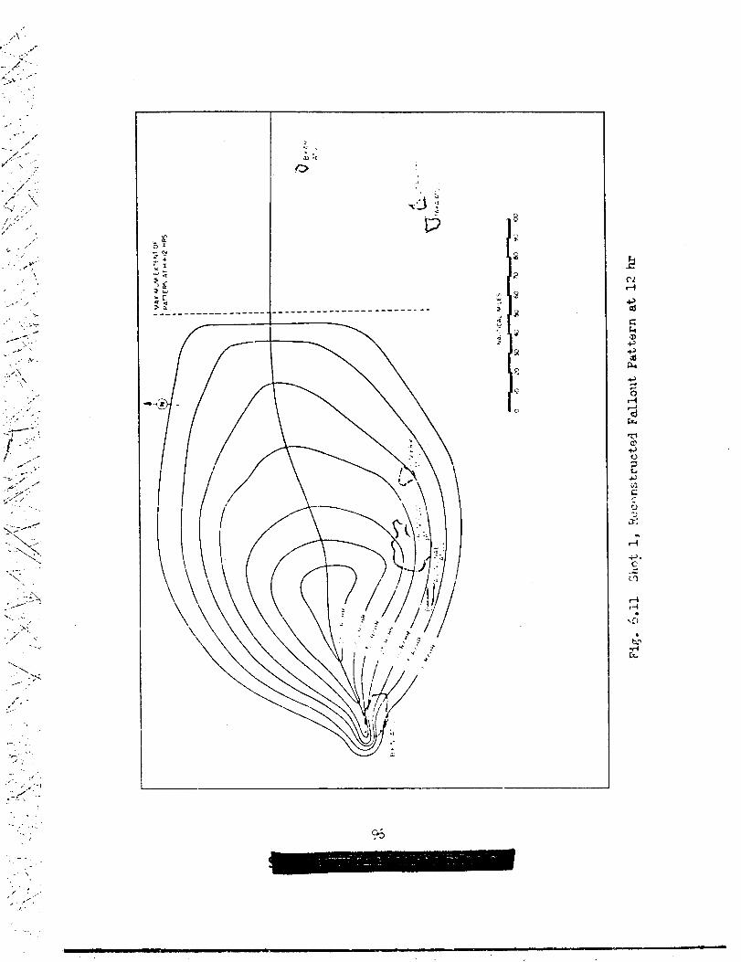
,./.\’. ,,.--........,/??’-.. . . .,...... - .“”
,,.
,.,.”
--,,
//--/:<
/“ “L‘,..,.
../-
.. ‘L-v’ ..’,...I J.;“
:/”” .’,//
,. ..,.
., ,.&,
,, .,---- ./
,>,., ,Y
->
..-’; , .. .
. --” .\,\ .-,..8.Y
...x
\. .:
.’7>;<...
J’,,...-
.,
.-.;, ..., .,
-. ;, ‘..’. .’.!
/“ .-. --,-
,.... ... ,.
..
-.. .
i‘., .
/’,,, -/,,
/.
.
.,‘,. ,
~.-~~~.t;: I-------------------------------------------
L
‘%

.’ -,...A
-..--,
.. ,’.. .
.UL”,/.\,,:,/--”-
,.,..,/
/,,,.
/“-,,-,.. .
..,.Q.,> ..
. .<,,,....-,/
-. +---/....
;-w.‘...
.i.,:~— -
../ ,.
... .
. ,~....
... ‘‘\,
i ‘,,,j,’‘1”
;,.b., ,.,
. .
“{/.,’. ,’../.,-,
--..- .. . .
.- -.’---- -.
.,, ,.
‘-.. i., ..
./.. ,
;,/’,,
—
\
z .J.,
.C#
“@-
\
\
$7
.

/’,.,
..?
;,.;’
,/ ,.. .
----
‘\-------
----
-“/-.. .-
/’,_.-
“1:”/’
,.;,/’ :/
/’
.<,
/.,
;,..
,.. --. “,,, ‘=.
,.
,-.. .,‘\..’.,
-..-.
/,/-
,,,.,“
~’ ,/
,
.,/,- -.
\‘\
\‘..-:. .-.
I+— --
I
F ‘~_--:_-_...—_.
I{i-—+-—7- –
I
I—.. –+——— +-—
I
+I
I–-t- .
\_ .—-+
98
,..-
,.

.,-./.
Oow”00.0
+., .
/“, ,./’
.-
---@--- -2,: ...-“.-
.: ...,.‘\‘-,,/; ,’
.
,.
.,
. —-.,* ---- -% -... /~.. . ---------- ----~(:
: 0“ --- --- -------
: 2+” .- -z=~k;\\~--------------- --.-~-.. k’z #“- ~e- ~.--- /2 [email protected] ------- -------- /::’.-
,/. “ -CJ&
. . . .. ..
A. ..-.
,’. .
\.
-.. ./,.
/‘,.’,/’ -
/’ t*l.,IL
,-
‘ \..-+
\,,
.
/
99
./’
.._.....
=-.

,,
The fallout contours cons~ructed fron the gummed paper data are presentedin Fig. 6.14. Since the data were fr~.lentor~,linited reliability..should be placed on tineccnfiOmation of the contours. No rmd.Ysis oftne pattern based or!perticle t,rajectovdata has teen attenpted.
..- -..
,,’
. . . .
-.;,.,
---,-.,.,.. ----:--
-./’
i.. ... ... ..-
.
>., .
,, :,’\
-. ,.~.. -.‘> “.,

,-
--. .
- -=/. .,.
,..-. .
..-.
-:.-. .-
i---..,!-. . ,.-+
, ..-
{.”..
! ,,
;’ ;,
/:,,,,
i “
..,. .”,/’
. .
-. . ...
. . . .
-. . .
.-/.:’.4-
;.. .
‘,‘\\
cIMPTiH 7
SUMMARY
The study of thernonucleexexploslorisat C~LE has show. the faU-out problem to be of considerablyCreatir magnitude than predicted.This demonstrationof the radiological capabilitiesof superweaponsmakes it Imperativethat scaling relationshipsfor fallout bs deriveduhich will,apply over the nntire range of possible weapon yields. Acommon basis of development is required if predictions are to be vslidfor the now undocumentedmedium yield”r~nge (high yield fission—lowyield thsraonuclear). Such a b~sis my te found in the changes incloud geometry which P_-e!aown to occur with cnangx in yield.
The increased c~ver~e by f~lout ap~~s to be due to the fl@tt9n-in~ of the source cloud at ilighyieltisin contrast to the more nearlyspherical c10u4 shap of the nuclear model “usedfor tilepredictions.The following general o“oservationsmay be draw concerning fallout fronthe more diffuse source:
(a) The ext~nt of land gcumnaradiation fields of militmy signif-icance is increased beyond that directly ettri’butableto the increasein yield over the nuclear rme.
(b) This Increase in the area cf lethality is the result of emore even distributionof ?allout over a larger area. Stating itanother way, reduction of the extra-lethalor over-kill factor extendsthe lethal range for fallout.
(c) The increased efficiencywith which superveaponsdisperseradioactivematerials is to some extent counter-acte(iby the delay in-ival of fallout from the high source C1OU? end the rapid rate ofdecay which occurs in the ~nterti.
ihrther study of the interactionof these three factors and com-parisons with nodel data are expected to ~eveal the part -loudgeometryplays in the distributionof fallout. Co=rdatton Of data fron ~1CASSLZ swrces, includine the results of water sampling under l?roject2.7,will be made using the VS!iRDLexperi!!nt~ model, Ideelizedgamma
101
. . .

( ;“
k;’‘\ ‘ii , ~,
!,J.,.-!’/”..
/\.’-
,/-’
7“”..
----:, .
.‘ \
‘,,,,’
.. .,
.’
\.,
‘..\\
l.. .
>-“< ;
Y.,’
/’
....
. . .
,.
,! .
;). :;,.. ..
‘\\. . ..
,.,-
..
.4
,.
-..
,,
. .
.:’”:\:,,
.,
-. -.,.( ,.
isodose and isodose rate contour plots will be developed for the twotypes of explosions, surface-landaml surface-waterytaki% into acco~~ttb time of fallout errivel. Comparisonswith olher”modelsend.uithnuclear data vill be carried out end the cloud geometry factor exzm.ined.The cmtribution which these upper yield limit data meke to the develop-ment of scalin~ relationshipscan then he fully evaluaterl.
Inprovexnentsof and ~eneralizations.on the experimental.zodel areexpected tc accompnny zhe foregoin~ anelysest Use of the method as atod fOr f’OreC~%in; prtiary fellOUt arpears p:’cnisi~ and wfll be ex-plored.
Additional development and evaluation of data on gamma field.decayv:illke carried out. Idealizationof the decay curve from 5 to !’2’0hrPost detonation is expected to produce a simplified appro:chn.ationsuit-~We for military planning and field use. This approximationmay reduceto two Straigkltline functions on a 10gariti’Untc plot, one covering thepe~io~ Nom 5 to 50 hr, snd the other, 50 to 5CJ hr. Later decay isassumed to follow the normal fission product function.
7.3 SFIXIFIC CCNZV31CI!S
The following conclusionspresent evaluation of datafallout at CASTLE:
on primary
~-1 z(a) G~m fields fron fallout decwed at rates differing from theap~roxi.matloncommon to fissi6n weaFons. The extent of this d3f-
fe~~nce is ~i~it=i~ ~Wrt.mt over certain time periods.(b) Fallout from the surface land detonationswas in the fern of
irrebylw solid particulate. The geometric mean partic~e diameter de-creasedwith distance from the shot points; for Shot 1 the geometricmean voried from 112 P at Eikini Atoll toL5 p e.tUtirik Atoll.
(c) of the solid particulate studied, approximately25 IXX centwere in.~ctive}Iitht,hefine~ particle size smaller than the active.
(d) The average density of the solid particles from Shot 1 was2.36 g/cu Cm-
(e) Little data were obtained on the nature of thr fallout fromover-vater shots. There was some indirect evidence that the fallout50 nautical miles fron Shot 2 arrived as a fine mist or aerosol.
(r) The ~d rate of ~riv~ of f~lout ue~ documented ofly \Jith-in the atolls by Project 2.5a. i{owever,limited results on more distantisln.nlswere obtained for Shot 1. Arrival was cha~acterizedky ~ rapidrise to a peak followed by a decline which, in the measurement of ga.’madose-rate,merged imperceptiblywith radioactivedecay. !’@til-idftistarrived ct appro.tiately l/2 hr after detonation and continued for1-1/2 to 2 hr.
(g) A continuous100 hr unshielded exposure after the detonationof a lrfi!Tdevice on land will result in a mininnm free field total doseof 1X r over an area as lar~e as 25,0aosq mio
(h) The develorxnentof an experimentalmodel has provided a meansof re~o~.s.tructingfel~out pat~rns ~si.nglimited gemmaco:pretwnsive analysis of the .vteorologicelsituationparticle trajectories.
Conclusions as to the u~efulness of free-flo’ting
102
field data pnd aas applici to
buoy stations for
.,,,.
.. ... .>.. ,

-L , -.
/’
.,,,
,.. .
..-.. --”
!.-k
.7.,.---_’_/. ..
.1,.-.. ..- .,,
documer,cing fallout can also be drown. ContI~ry to +,heresults obtainedat I’JY,the epnlicabilityof this method without modification to super-
.1
weapon tests anpesrs questionable. Late chon~es in the predictionof ,winds aloft induced uncertaintiesin shot schedulingof an unprecedentednature at CASTLE defeetin~ efforts to mount eny operations requiringadvanc~d timinu of the oxxlerof U to 1.?hr. Hoxever,., in one 01*the twoinstanceswhere buoys were in place at deton&t,ion,valuable and otherwiseunavcilet,ledata were obtained. In Ceneral, medificationsof the tech-nique1srly
7.4
which
are indicated prior to uso at any future weaponst test, particu-superweapons,
RE501?!EKDATIONS
Knowledge of theradioactivity1s
geometry of the source clod and the manner in .--
associated with it has been shown to be of majorimportancein the Prediction of the fallout. More detailed study ofth~ cloud qeometry”factorand of the ~r-ticulater~ture of fall~ut atfuture tests is recommended. Such studies will require cloud samplingof some type.
Continuous wind data to 48 hr post detor~tion with adequatesctellite station coverage should be obtained at fi~turetests wheresignificantfallout is expected.
Re-evaluationof methods for documenting primary fallout ptternsat the Pacific Prwing Ground is recommended. This ro-evaluationshouldtake into account the increased import.ssnceof the fallout problem withref~rence to both operations and security.
..,.
\-
,-. . ‘-,, .,,‘.. .
,x.\,..,.
.,/ ,,J.,-
..,....
. .
~..-., ,,.,, ,’
. .
,.
\,/ “
.-
.,
.,
1C3
.,.
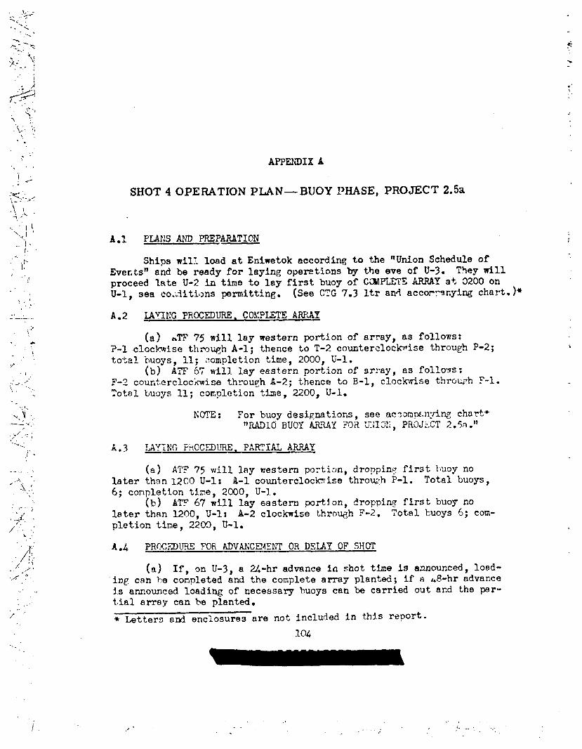
l,. -.. ..y=<. . “<
:...>!
-=.----- - ?=
~,. ~
;(. ;’?I
#. .
!’ .,\
i :,‘iH. ‘(,
\, .,. .
. ‘,’‘.. , APPENDIX A
/:.:
<=-..).>,: SHOT 4 OPERATION PIAN— BUOY\!,!\.4,.,’-
‘Ii,‘ \.<j
‘1- A.1 PLANS AM? PREPARATION..t.
,.. ‘,h
!, Shim will load at Eniwetok according to the ‘Union Schedule of. 1!
!. Eve~ts’tand be ready for laying operations-byproceed late U-2 in time to lay first buoy of.U-I, sea coi.~itionsprmitting. (See cTG 7.3
!,’,’
.. A.2 LAYING PROCEDURE, COMPLETE ARRLAY,,:J
(a) hm 75 will lay western portion of.&
7’!.
. ..’ .:.*.,., . .
.,,.“<\ ,.._ .<,
.’./ ..:/’ .!
,.%,. .
,! .
. . .. ..
,.. ,
... ..-,. .
/
the eve of U-3. TheytillCCW’LETSARRAYat 0200onltrand accowqxiyingckart.)*
array,as follows:?-1 clockwise through A-1; thence to T-2 counterclockwisethrough P-2;tot21 buoys, 11; ~~ompletiontime, 2000, U-1.
(b) ATF 67 will layeast.ernportion of srray, as follows;F-z ~oufitercloc:wi~ethrough A-2; thence to B-1, clockwise throu~h p-l.
Total tJu12ys11; completion the, 2200, U-1.
NOTE: For buoy designations,see ae~anp+.n:nngchayt+“RADIO BUOY ARRAY ?OR Un;IOE,PROJSCT 2.5a.1)
(a) ATI’75 will lay western portion,dropping first ~Iuoynolater than 1200 U-1: R-1 counterclockwisethro~,h p-l. Total buo~~6; completion time, 2CQ0, U-1.
(b) ATP 67will lay eastern portj.on, droppiny first buoynolater than 1200, U-1: A-2 clockwise thro-qh ?-2. Total ‘cuoys6; com-pletion time, 2200, U-1.
A.4 PRCfXDURE FOliAdvancement OR DELAY OF SHUT
(a) If, On U-3,a 24-hr advance in shot time 1s announced,load-ing cnn be conpleted and the complete array planted; if e J3-hr advanceis announced loading of necessary buoys can be carried out and the par-tial array can be planted.
* Letters and enclosures are not included in this report.
104
., .. .l....\-,/ .
.-.4
.
.,
J

● .
J_:,’-./
.,.,,/:-
.-Y ,’
,,/’ ,,,
< ~.:,,.
,..,,
,,
,-
‘- --+”-.----...’,, ,,;:,,,
./
,/ ,,,.
/ ‘..,,,. ..
.1.1.,
( 1.:’,:,, ,
.,., ...
~. ~,:,. /‘/.. .
)’
,/<
..’.-
,./.,,.
‘/” ‘,, .,/., .
./,’: ~,z/
/’. “,/
,/ ‘
if–~.:
(b) If placement of either the complete array or the Frtialarray is proceedi~ and a 24-hr delay is announced,buoys alreedy plan-ted cnn be ieft to drift into new positions cnd additiorfilbuoys laidupstream at the proper time to round out the array.
(c) If placement of either array is proceedingand a dalay of48 hr or more is announced, buop planted must be recovered. Eitherthe complete or partiel array may then be set out as time and circum-stances Dermit.
A.5 RECOVERY PRCCEDITRES
Recovery operations are expected to coimmenceon U day. Each ATFwill recover o~n buoys, commencing with st:ltionsin pro~ble f~lloutoIf recovery ships themselves encctinter faliou+, they nay retire and re-cover buoys in adjacent areas. Every effort shouid be made to recoverthe imyx-tant stations as early as possible; however, if recoveredbuoysproduce dangerously high radiation fields aboah ship, it may he neces-sary to break off and return to %l=t,ok to off-load. The ships shouldthen return immediately to recover remainder.
A*6 KESSAGES TO ATF~S FRa” CTG7~
The following information should be included in messages to ATF’s.(a) Message to procoed to lay kuoys should specify plan desired
(complete or partial). Project will provide information.(b) hiessageto proceed to recover buoys should indicate probable
area of fallout 3Y buoy desipation:. Project will provide infonzation.(c) Messages to ATF’s to Tcodlfy laying procedures on-site should
iccluje specific recocunendations.Project will provide Mronration.
A.7 hUiSCAGESFRO!:ATFIS TO CTG 7.1
(a) Each snip should report wop.Jss inlaying operations everyL hr. Stations and their positions shjuld be reported along with thetime of lajting.
(k) During recovery, each ship should report progress every L hr,giving time and position, and radiqtion levels of sampie bottles asdet~m,ined by Project personnel aboard.
(c) Info CTG 7.1 onallmesseges.
,-.’ /.,“.
-----/’;,/. ,: ,,/ .
.“.*lG5

e
AP.%KDIX B
GAMMA ACTIVITY MEASUREMENTS F’OR THE TOTAL AND GUMMED
PAPER COLLECTORS
T~LE B.1 - G~a Activity Measurements, Shot 1, Total Collectors—
%li_!i:- of iolid T.’t.of~——--—— ...— ——
! GanunaActivity !leteand Time‘1No. (g) Liquid [ (mr~
, (ml) Liquid—— ____
I~——
251.C2
251.03
251.04
251.05
251.04I
251.WI
1
I
I
251.08!
251.10
250.04 :
250.05
250.1,s
250.?2 1
250.?4. i
2F?.69
803
5*Q1
1.61
1.1’7
0
1*Z5
3.58
0.26
0.14
0
0
0.21
% 345
u
L
6
0
120
138
124
Lo~ ~8
II 55
16
,i
82
79.6
E!i.1
l.$?
0.91
0
0.9
0.13
O*23
c.96
0.58
0.13
0.058
0.40——.
r) - ~~eas~red (?ST)‘Solid–l I
i——.
27.7
2*O
o
1.3
0.%
7*2
3.5
o*~~
0.31
Ooa——.
106
A

>r
...
/’, -.
~,-- -“ *-k.,
..f.
‘,,~ ~’”
‘/’”-,./“
/,,,,;<, ;
/ ,-.. ,.. ..
i “;A-
,>/;>./’”
\
‘“R,/
,.,/,, .,
.+ >..
TABLE B.2 - Gamma Activity Measurements, Shot 1> G~~Pe~er Collectors
I251.07 I 1.2
I 251.08
! 250.05I
I 250.06,
250.17*
250.221
1.0
4.3
3*3
2.3
1.9——- .–—-—----—
———--—
Date and TimeMeasured (~) 1——— -
7
4/29/54- l~o
4/28/54- M@
4/28/54- MXo
4/20/54- KZo
4/28/54- 12@
4/28/54- lZC
4/28/54- lZO1
TABLE B.3 - Gamma Activity bleasurements,Shot 1$ G~edPaper Collectors
.—-— ———-.—— —— .--— ..- —---—------ ----— I_ — .- —.—- —.. . .. .
Sample No.
— .-— -. ...-. ..._— ‘1Gamma Activity Date and Time
(mr~r) , Measured (PST) I—–-t ------ . ..
i-S+Mo 0.0008 i 3/18/54 - u~ t
I
14-?M
1-S-!IWJ! 1 I
l-s-m : 0.0021 ~ 3/18/514 - IAoo
!lA-DWL 0.0021 3/le/54- Uoo
L__—------..— 1 1—.——.
107
.‘..;
. ./ *
—————- ..- —- --

‘;””’;/:
TABLE B.4 - Gamma Activity Measurement,s,Shot 2, Gummed, ;> PaperCollectors,.;..
1 —— >,’ /’
:\-’‘,.”/‘;
~
Sample ~ Bearing“\ No..— i(DegreesTrue)
/;:,</’1, 1 A&-,:!2\ {/..,
.’>:.:.”
,,.‘
/“
II 04
! ‘4. ,. i A5---- ,
,,./
/“
ID5
‘5
‘5
‘5.—
I 352II
247I
271
2951II 308
337
I 347/
054III 075
I W5
I115
L —
——
Distance from GZ(nauticalmiles)
——
43
34
34
34
36
43
52
53
53
53
53
108
GammaActivi(mr/’hr
1200
5
20
2f30
5000
2200
UOO
0
0
0
0———
——--— ——-
)ate and Time I;easured(PST)~
~—.
)/27/54- 1930 ~
)/28/54-1820
~/28/54- 08L5
)/2$/54-1200I
Y/28/54-1300
~/28/54-1520 I
-1
— —. _ ..—,
I
.-.— I
.

/“ ,,.?’
/
..
...>,, ./,/.
/\.
. .. ,../.
,, .<.
/’
.. .;..,<AT,.
./ ,’..y,./.
..
/’,- ,
. ..-. ./’,
L.-
--- +..
/,.. ,,, .’
.
...
\ ““..>/:<’\,
- -.., -.
,
TADLEB.5 - GammaActivityMeasurements,Shot 3, TotalCollectors
Sample No.ILiquid I Solid
(ml) ; (g) t-Solidm:
251.02251.03251..04-1251..04-225~*04-3251..0$253..10250.05250.06250.07 ,
t———————
1’7851630U7521301150325
1665
250.C8-1 : 110250.08-2 170250.03 ! 61525G.12 : 75250.13250.U-1250.14-2250.15-1250.15-2250.16250.17
2452353203802$260
2$0.18-1 I 515250.18-2 i 56o250.19-3 365250.19 93825G.22
1915
— — --—.——
i- 30010 0I 0.34 0.17‘ 0.34 0.16‘o ]02.303.44
0
0.120000
0.?70.17
2750
1503.370000
0 ‘oo 0
:0 0~o o;0 o1- 280i 2.81 51.8;0 o:0 0:0 0
l_-0 ! 0—-——...
Ctivityhr)Liquid
3.280.410033oe~5
0.420.39
9.92
3*552.1+5O*590.110.:1900~8
0.41O.?J0.417.32
134● 619.36.941.110.92
—-——
Date and TheMeasured(PST)
4j8i54 - moo4/15/54-15004/15/54-15004/15/5L-15004/15/54-15004/15/54-1500
/4/15 54-1500418 54 -1630
/4/15 54-1500418 54 -15304/15/54-15004/15/54-15004/15/54-15004/15/54-15004/15/54-15004/15/54- lmo4/15/54-15004/15/54-1500L/15/54-15004/15/54-15004112154-09004/15/54-15004/15/54“ 15004/15/54-15004/15/5L-15004/15/54-1500
.
..
.-
.
.

. .
.. +--”
\,
“~..
/
,’ -
,/”\\‘$,
,, ,\t.
....’..
TABLE B.6 - GammaActivityMeasurements,Shot 3, Gumed paperCollectors
~.— .—— — —1
I
!
,mp,-
—.
~ 251.02
I 251.03
251.10
250.05
250.06
250.07
250.16
L Zfx).l?
,... -----
-..,. -.
!
/110
.../
—.—.—.- —

/. .
\\,
-----.
.,
,/,‘//’/’”’,, .,
“-2
.
.-
. .,-/.
. :=..-,“
1
““[”,,”
/ ..— —-. , —. —.’
.—I I
u
●
G..—●
111111111 t I II I II I I I I c1 ~
I
111111! 1
1I[
qmoom aliii\+ i
t@)”go”o”o”ooooo oooo~oooo: ;II
—— -{I
I-++~.vnw -# [email protected].+mm!+m*m (0
O“.”O”+O”OOOOO 0000000000”
——.-
l“d
,“.
/
.
i!J2E+
.-SI

0-- ,.- “r
. ..1
..-
,.-:’-\.-
‘\.. ‘.,’\
! . .
,./.’,
\ .,.
,/ .””.,
/“’/
‘,
.(%
;’ ‘\\\
,,,, ,,
.. . .
.....
>----... .
. ,’‘. . .
...‘\
. . ,.“.,
,/: /’
.x;/’ /
!.
!.. .,,
.1.”.’“,
~,
, .>..1,
‘-’.4BLE B.~ - hnma Activity L!easurements, fiot L, Gummed PaperCollectors
——..—.———
Sample No. Ganna Activity Date and Time(mr~r) Measured(PDT)
251.05 2.91 5/5/5.4- 15~
25C.05-1 IL5 5/5/54 -1500
250.05-2 115.3 5/5/54 - 15Qo
25fJ.U7 0.54 5/5/54 - 15w
250.1? 1.07 5/5/54 - 15w
250.22-1 I.u 5/5/54 - 1500
250.22-2 0.?7 5/5/54 - 1500—
.
\
.,
. ..- ..
.+,.-1 .,—! ,.
,. ..,,.

/
..”
TABLE B .9 - Gamma Activity I!easurements,Shot 6. Total Collectors-... ,,’
/-
--7----
:.?“
.’,:.:-+. ‘
~.” ., . ..
.>
:-- .,.
,.+ .-*.,”.,,. <..- -
(.‘,..’\
.——./“
,.
<./,”” .>
,.. - L..
r-”
sampleNo.
— ——
Alice-1AM cc-2Alice-3Allee-LAl~Ce-5JaDet-1Jaset-2Janet-3Janet-LJanet-5Janet-6Leroy-1Leroy-2Leroy-3Leroy-4Leroy-5Leroy-6Leruy-7Leroy-8Nancy250.2?250.28250.30250.32250.33250.34250.35250.36250.37-1250.37-2250.37-3250.39250.41250.47250.4!3250.49-1250.49-2
TotalVolume(ml)
~lo
610U5460L50332275250L15465455725720725750760705815705305593655660450455462L503502110175015009313935875131515201335
Fit. ofSolid(g)
o00.0811.035.534.314.370.0720.4301.3500000000000000000000000000
Gamma Activity
JSolid—-—
00.47800.3560.5000.3600.3280.’3$2O.Z!J0.232O*W00000000000000000000000000
4r)Liquid
1.952.760.3550.8162.L7o.038L0.07970.0621ooln0.2370.2200.00770●005790.004820.004820.006350.004820.005400.005000.1490.2800.07L20.02820.3220.%850.1170.0111.110.0%35o.oo7150.00770.01350.0081c.Ocdl0.01540.006350.0054
.,./
...\. ‘\$!
.!. . ‘.,
‘\ ““!.
. .
l“ . .
/
11.3

... .
.,”.. .
‘ ./........”
,.,
/,’
,1-:,
.
-,.:
/’X’( \.,}. .
\,t ‘ “:,.,“i,;,.,,
,!
-~.:% .>, ”-.-y.%
..’ i .’”?’.
/
\‘\
“.
.;,
“:.%‘!.. .
~.‘\ “’..i,.. .
-’ ~....!..,.
,
,, ,, -,-----
--,
,,.-
/’
TABLE B.9 - Gamna Activity Measurements,Shot 6, Total Collectors(Corlt.)
—.—
sampleNo.
250.49-3250.49-/+250.49-5250.49-6250.50250.51250.54250.55250.58Barge-1Barge-2Barge-3Barge-4Mack-1Mack-2Oscar-1
TotalVolume(ml)
13107801085u?!)1225I3,1O10859607651115lUO1010105019151528710
wt. ofSolid(g)
o000000000000000
—.
—..—
Gaii Activity—4!!?Solti.—
0000000000000000
lM
m)Liquid
0.0U820.02L70.004250.00770.01640.009060.009250.0050.00578001460.270.01510.1390.03380.02780.0117
b!easured(PDT)
... . \ ... ., /, ,

.,.\.;\..,
“,.,
--H -
/
. ..
.,
. . .
/,,7 .<..
‘/‘“,/,..:
,,.. . .
,/’/
i:
- ‘:]’”./’, .. .,,’ /’
APE’!M?IXC
PARTICLE SIZE DISTR1~UTION AND PERIOD OF FALLOUT DATA,
SHOTS 1 AND 6
115
,---

,.<’ ‘1-.. .
.-.
t.. ../. i
,’i
.,1.
-..’
. .,,;..
.
I
1 ,/
i ,<II‘!’ ,/j“ “
,,’,>
,’
!.
:,.,,‘i.
z
sot.+-0
z5!4-m+0
.—
zs0t-u
A J!!!
CILO.
006
000
COJ.
009
Coc
9CJV
026
Coz
(101
3
0001
006
oo@
Ooi
069
00s
00*
CCC
002
00,
-~
0001
006
000
OOL
009
Ooc
C’3*
Oof
00.?
oa~
G
t’
0001
006
000
OOA
009
00s
Oov:~’
002
cc I
5
a,. OCOI t!
+ Io I
——-
C08 :
@oL
c 99
0 0s
cc?
Soc
202
-JC
o
0001
0f)6
Ooe
001
009
oo~
09V
rJc
302
ccl
c
‘f, :... .
. . .
-. ,.,$
S31311BVC430M3awn N
116

‘“j .’”\.: ‘
i““i-‘,,.,
/.,..,{’:!:,/
-.. ,-7- .-/
,’_%_ . .. .
.. :,
,L’-----
,“‘\.L.—..L .-.
‘, .i”/..’.
, j ‘::;
1’.
-L -----\.,.,
:\, _-..
,- ,. .,.,
.’, (1.
1.—-..:.,.,1,
,~.
! ;\.,! ,,, .,,’. !
;’-4
‘,“;,,-.
.Ls!dd!Jzz !Ill*
i,+d!!!iiz
sInF14-0
. ..211!I-.z I
JJQ
Scs
.’.’●
.’.’ f
.,.. . .
.’.’
~.\. ~a ,
L’C6
J:*
Cci
..,. q
.,-. . b
.’ .’ ?\. ..,.
. . .. . .
.’ .’
~,.c,
JC6
.’.’II
.-c...=..>...;
,’.’?..-..h
. .....
::C,
.’.’6J?*
.’.’.
ziiInm
To
t- 0001
I 006
006
o
-Hi,-Ooc“- Ooz
LO’
/
000!
006
coo
z OOL—50a?Lo
i009
005
wldlmidOoe
cog
Ooz
001

_.....\-.,. ,,...,.
/. . ..\
,,.
..i
‘\.:..
~..
\. ..,
.- ?- .,
,,.. ..-’.
,\’:,a.. ..,1
:.
.,----
.’ -
---- .
. ..
,.
--- .-
:.,. _
—
1(2001
006
009
z OOL
% 0090In 00s
loF-1+o
000:
006
008
r.,QL
009
00s
OC!*
00$
OGZ
CL<
c
Gool
006
000
30A
009
00s
Oce
30s
[
0001
.-006
“ 068z
s.-COL
In.- 009
m 00$To
co*
00s
L-002
00!
t- 0
113

f’-....,\-:...~’.\
\:\:<\;.
f..~\t
I
,!., .,
i\- ..---
‘.\ ;.,,(
‘i :,“’;”,,, ,
,’1 ‘,!j
‘ “Y.”’. ~..-.,,,,,?, ,:’,
>.’,
.\’:..;r\:V, .>,.
[
0001
036
_ 039
z 00A
ii 0’.29
z
50m
:
,,, 1
— 0001
L 1 ! 1 I I
.- .- 0 on 000““NIX --
I““”.
006
-.000
z 00L
5 009In(n 00$
+ Oovo
00c
002
x
001
L I I ! 1 I Io
z
s
:
:0
z
z
su-lo-l
+
o 40001 a
u006 ~
008 >
00J. ;
_ 009
00$
, 00*
- OGC
I 1 t ,%
_ 002
—20,
L c,
E
000!
006
000
z ‘~ 00L
5
, ,1A
-009
0b :- !)Cs
+ 00*o
mc
— 002
00 I
c.- o.~c~ a a ‘-.,,.-, ,W *
i1’
,, ‘,. . ...
‘/”.~. —:>.h, “
‘/.;,’,,
,,.
:: ,’..
; --
119

,.-/:-. \.
,/ ----i..-
./
.,.,. ,-----, .-..
.,.’‘L
>1-:.
“)”“ z:’.,\
‘. --
-“. -,.. ..
,.,,. \
-:..- ~-.,-
.-. ,
““i../’
z50m+o
1-
b .Gool
.cI06
00 e
-COL
009
-00s
z
50m-l
+
0
1“0001
006
--008
0—+0
2
su-ia
+0
-
z
ii
o0
cool
006
008
GOL
009
’30s
CO*
Ooc
4 C02
cot
—! D
s31’JIl&P~ jo /j; Q&PN
---
‘t-120
6

,.
/“ -:
,.-..!
.x,,. .- -
....-,
.,.,.
#;j---
.“ ‘.’.,.-
...:
/. ,/’.,-
/’
. .
.. :
,’,:. “:-
—...=-. . .: ..<,..>’- ,----%. . ,..’
..’ ,.. ..-.’... -
,/ ., ;,.
4.~..<. ..; -
, . . .
.: ,.:
,,,“1, -,,.
./:,,...-,,...<
0001F
E006
309z .—COA=:+o
.%
——. .— -——— -——.G
[
Oocl
206
-- Cao
- cod
009
/
COG
2C?
: CCi
:02
E0001
006
Ooe
x
121
9+In(-d
r-l
.—-. -.—. — —— -.—. —.- .—— — —- A
a— ..,. .. . , .. -.’ .- ..—.

dSool
: 006.00s
20001
006
.-008
– OOL
10001
006
038
z001
5 _ 009
In(u
o0s
:
13
--Oov
- 00s
002
001
—— 0
r0001I 006
009
S31311MVd 40
I0001
- 906
-008
a
I0001 i!!
“10C6 g
000 :
z OOA
5 009
4 Coz
?0 ,
L—L—————————— o
,,,10001
006
Joe
z 00A
so
GC3
c 00s
T OGVo
Ocx
3C2
-Ocl
c*IWU5., Q-U
ol-l
●
co
svw-l-PL
Isd
1?~*.-
*..$ ....’. .-%\..\ . . ,,
.. ... . ... ....’ .,’.

...-
,..’
J,“\
(.,
:..
,.] ..,”
.’
J“>;:..J’\\j,i,,:.I,,f,,.1/
‘f
,.;+-’-..—
/“~--:,,..’ .-. .- .’
‘, !
‘\.“. , ,I. . ... .., ‘“l“i-’.:lb
! ,’/.
,;.,----
0001
E006
~
008
z 001:d _- 0090,.V 00s
L Oill.
cot
002
.--co[ ,, !.
-6
.–0001
[
006
-- Ooe
fiooL
309
005
- OC*
j
:- Coc
—002
00
-. c.,0 CJ CJ?a
2a0 0
. .
+0
,,,~
000 I‘– 006
---008
001
: 009
– Oc’i
M.*z
00s ~
–OGZ :
--00: :,, -.
03
a
F
0001 :
006 :
z;-0C13 s
s-oC/.
;G
u-)
i
C;9u-l
-LOG+o E–Oov
:- O(’i
i
:
,,
>
. .>.’, .- —.—T s ~ ‘--—---’- ‘“-–-”--‘“
. — —-.,

/.,,
., .
. . .. .’:
,;j
/1 .
,,.’
\‘\’
t-..’ . . . ..;. ‘
i ‘.
,.6 _
[
—
TIA
0
05
104_—
,03 !!
o Is
—
\o
!
L
--
l--.——
-J_L4105 120 135 150 155 180
I
—60 75 9030 45
TIME (MIN)
Fig. C*9 Shot 1, The of Arrivel and Period of Fallout,station 250.05 (A,B, mc? C as in textPO 69)
?
!’ ●
-
----,“
——-/-----. -”---‘“:“.“’ .
,/ ,.. . .

,-‘. .....
!’
._ .,,, .,.,. .,>“:. .
,/ , .-...
‘}”.. ..-,--.\“;l-
—
.-1
$-1’—
J——
.—
—.
f
—-
; “.“,
. );’“.+”“
..-.
-..
——
——
8
.— A
,(’J3 _--Lo 15 30 45 60 75 go 105 120 135 I50 165 180
TIME(MIN)
Fig. C.1O Shot 1.,Tine of Arrival and Period of
Fallout.,Station 250.M
‘. ...’,. .z -
,,, - . ----.,i-’.,,

--- ... . .
.-
; [’:”.,/,// T
_-—.1mi
1
—
—
j_.——.
—
/.
,!
---–. .. .-. ...
105
P_.——.------[
-—i—
I
45 60 75 90 105
●
●
)
40
: 10. .._.I
>.’;I
—.
t’ir.—‘1
————.
?
..
—
L.:
, ‘>‘,-<“”
:~:
L,;..a
.. ...-,,
.—103
-—
v
—.
:.../’1
“-f.. i/ .i .<....
:;- ..
,,—-../,%.. ,- :,- “;. .-.s.,..
102 120 135300
TIME [MIN)
‘if. C.11 Shot 1, Time of Arriv:~lend Period ofFallout,stRt~~n 253922
1“26
,.. .\“...:\.
+.!:.
. ...
.—
. . /“. ,.. .. .
.. . . ,-- ..;: -.. - . . .

-,/,..,,
‘,,,-
‘,1,
~:,;,:’... ...‘. .,,
,/,.
“ “Y
.,,,
,....+c
‘\ ‘...
;-\,.. .
‘.. .,. ,. i.. ,- .-_;;&..
(
.[ ,...’j’ I
/“;,;y\
-L ,J-.,./- ‘
,. ‘, ,:-.,
—
B0
10*I ~—0 15 30 45 Go 75 90 105
T
TtJ_
TIME(MIN)
I’fg.C.12 Shot 1, Time of ArrivfilFallout. Station 25’:aZ
127
co
120 135
and PericA Of
——
h5 180
,“ !.,.-.+..--;. .,,,,,
.,,,’ .,,,,-
<, .-,. ,.. /.,...,’ ,. .. : ..-i? “’-.”’: ““’ .,’““’ j . . .. ‘i. .
...). ~. . . . f . .....,. ’,! .. .. . .

\,
>./.. .,‘, >
\,,-.,
!“
>:<; . ‘..’. ,..
-,..-.L..;.. . .. i“,,,,,/;”
y.. .. ..!,,\ “
.., -,..,+’.,‘-,‘ I,y.. ~,.
>;-.,,.,’. -( :. I., ..-,,. );
t’.,:i ;’
:? . ,) ..,-. ‘
..-. .
,-
106
F
).28
~’ ,
1
. .. -. . ..- ,., .-,.,’ -., ,..,. ,,.~-:+.;. ‘,”,’-”’,’:+ ~ .,“:,,. ,.. ::.:,;$, .. . ..<.’. .:’../ ‘----- . ..
‘.. ,, <,.. . ... ..~...
.. .../...,-..,., .’., ,j...’.-’ , .: .-. . ..,. ’..>..! . . . . . . . . . . . . .

106*
T
—
1
(
%/
—-. —
—.
0 Is 30 45 60 75 9~ 105 120 135 150 165 180
TIME (MIN)
Fic. C.lL Shot 1, Timeof Arrival~allout.,Station 251.05
end Period of
..A----

., 106
, (35
:
: 104
*va
103
102
——
(
‘pTi!
d.-
II
—.
I
I
!
;O1~’
:.
—
—
.—
FJ—-t—.l_–
1’
—
—
I
--L1
——.I
I
II
I
—-L--0 Is so 45 60 75 90 105 Izt’j 135 150 165 180
TIME (MIN)
F~. C.15 Shot 1, Tbe of ArYivel and Period ofFallout.,StntIm. 251.06
,
. .

. —-
‘.,
.’
0a %/
I
I—J_
h
— —.
——
— .—
—-
P!.—4c?0
——
1
_l_-—0 15 30 45 60 75 9(3 105 I20 135 I50 165 1s0
-.
\
. .
/b
f’
r“
TIME(MIN)
FQT. C.i6 Shot 1, Tim of Arrival and Period ofFallout,Station 251.10
-.
131 ..—. _ - 1

_ .—. ——
..-
.
-..
‘,
\
. .
!.i
u
II I
I/II I
.—
0!
Ill
L/
J-l-L
/
II L
4/
Lu-.
SAMPLE NUMBER
Fig.C.17 Example of RelativeBaclcqro’umActivity,Station 251.@ (s&nplerexposed but didrid oporate)
.-. .. .
..
.
(“,
.-’
1

— —.
.
I05
104 .
>b
< ,03coa
102 “
10 ‘01
.—
..—
1—
—
A
L) 30 45 I
.——
—. -.
Bo
II
]
“1
1
I
—.
I
II
t
1
90 105 120 135 150 175 190
TIME(MIN)
Fig. C.It! Shot 6. Time of Arrival nnd Period of Fallout.Statio;Alice
?
d . .. . . . “.,-1..\‘i1’
-/ -.
. .
. .
----
....
. .A
. . .
<.,
.-
-.... .
..
..-
. .. .
.. .
133
.--—

APPENDIX D
FALLOUT PARTICLE DENSITY, SHOT 1
TABLS Del - DifferentialFallout Collector 250.04—
1
23L
z789IQu121?u15161718192021:22324252627
I
25
40405055758085
z100105110‘25130135130140Ko1403-45lL51.45l~o160160160
L28 16529 16530 17031 17532 i85
.—
2.2e
2.c15
2.542 .2L2.222.422.262a52~e~~
2.182.172*1G2.242.192 ●U2.221.?82.182e352.212.232.402.042.382.271.942,38
1.652.102.6?2.322.20
—
L480
102090058Q7301060810350750675550
2:590540260L90350 ~590 j530310480650340 ~380 t7005:5 t62o375570325
E?’. 1-
334
53
848689210110230214750266400
1056L1?1?G$L2313L361066164
;:66
:u24
llete;ounted
7/20
7/207/197/207/207/197/197/207/237/207/197/217/21
—
Color
white withorande tin~;ewhitegrayish whitewhitewhitegrayWlxitt?whitewhitewhitewhite&,hite
white
7/21 white7/197/217/217]217/217)217:217@7/22
i7/237!237)237/237/197/19/? 19
whitewhitewhitewhitewhitewhitewhitewhitewhitewhitewhitewhitewhitewh~tewhite1~hite—. —

I 12 !
TABLZ D.2 - DifferentialFallout Collector 250.17
13 iu:15 i16171819202122232425
26
SamplingTime(reinafter
AED)
1:101015152025354040
404550505050505050951-1o1351351601’75
— ———
Density;g/cucm)———. — .
2.422.522.502.392.222.662.402.512.552.462.55
2.5?.2.4/,2.372.332.362.542.J12.712.381.952.472.472.492.452.34
AverageJiameter
[P)—
80082083046033084052548036o26o1750
480680425350610320;:
6405606005307703cKl470
rActivitq(c/m)
———
61~61
;;163
E
;;020
051+600
12:40010I-3517
2928
Date:ounted
7/287/287/287/287/287/287/287/297/297/297/29
7/297/297/297/297/297/287/297/287/287/287/287/287/287/297/29
Color
grajdshwhitewhitewhitewhitegraygraygraymYgraywhite wSthbrown tingewhitewhitewhitewhitewhitewhitewhitewhitewhitewk~tewhitewhitewliitewhitewhite—
135

:..
..
.
..
..-
.,
.
-’
...
.
>
-.
.!.
,,.,
\
.’I
/
---
-.. .
.
,.
i,’
. . .
/
‘\
.
,.~, -
TABLE 2.3 - DifferentialFallout Collector 250.24,.,
———. . —
1Samplin~ Time
(tin afterAdD)
-—
5I 10
152025
I 35
I 2;i 65
65I 65
De~zity(g/cu cm)
2.112.402.382.222.752.662.622.L62.382.542.55
112 I 65I
2.6013 I 65 2.59
J__u 6515 6516 8017 9018 I:o
2.L82.362.582.452.c5
——
AverageDiameter
(P)
&o
980Q5240275675IQo335220535440340250250590200270310
————
yhctivity(c/m)
—
0Cl
2;121601460
3;42436544
3:24
——————
lj~t =
Counted IIcGlor7/227/227/227/227/227/22
uhiteuhitewhitewhiteIwhitewhite
7p3 white7/23 white7/23 wMt97/23 white7/23 white?/23 white7/23 Whitd7/23 white7,/23
L
white7/”23 white7/23 White7/23 white
.—
‘\\.
‘\t..
. ..i
I
.,
.
-..
l..
.- . .
.,
,’s,
,,”
-,.,’,,,
:
● .’.

.
ArrrJNdlXE
PARTICLE FALLING RATES
1’
‘i.
i
‘lhcdeterminationof the %l]in:’ rates for the fai;out particleswas rcadeby initially c~lculstin[;the teruiinal‘velocitiesi-orprtic).esat v:iriuusaltitudes. A select$d ran~e of prticl( dix.eters v.asusedin dcine there calculations. The diameters considered~ere: 10, 25J50,75, lCO, 153,200,2’0,375, 5C0,750,aid lGOO P. Teminal velo-cities for these particl~sLW.recalculatedfor strtin~ altitudes at5000 ft increncnts fro~ Clto 100,000 ft. Frm these cititathe ave?z-~ey~te: of f~ll of the :&tiiclcsthrou.;h513G0ft incrementsof the atrws-phere were detemined.
The calculatim of the temin:ll velocities involvci the use ofkao~m la’.:sof settlin~ 0!’ ‘ “~us~cn(lc.dTj.:rtlcl[: free ~tir,es.The t:,:esof
flot’uhich these prticles umier~c ~rc divitiw intc three re~io,ns:streamline,where vi:cous forces Iredo~.in:.te;intermdi:’t.e;~n~ turt~ent~where ir.ertiaforces pretixin~te. In simplifietii’cfi.,thu la~s Love~A-in~ these typec 0S flow are:~\
Strewdine motion,v~ z
Zntexwdiate rc~icm,v= .
Turbulent re~ion,
‘m =
‘m T
K=
Pe=d=
~.
“.
terminal velocitiJ’. .
const?nt, for irreCulcr qubrtz particles:1’/.2?.rd$ = 500&36, K1=-
ticnrityof the p?.yticle
denzity of the fluid
true diar.eter.
137
‘,●

absolute tiscosity of the fluidP =do-d
$=dl
The values for ~, ~ andquartz ‘prticles, which for this
g.
lfiting diame-ter to which thestreamlinelawapplies
accelerationdueto gravity
~were given as determined for irregularapplication is more suitable than those
velues given for spherical particles. The wilue of K1 was determined bysolvinc the Eqs. E.1 end d.2 et the point of transition (85P) fromstreamliner.otionto the intefi.edietere&iou.3J
The density of the ~rticle was detern~re~ t?xperimentsllyforactual f.~llout~rticles collected in the field (see Section 5.L). Thedenzityyof the air and the vircosity~~f the air which is temperatureaependent are sbovn in Tgble El. The values for the viscosity arebased on temperaturemeasmenents t:.kenin the Bikini area at Shot 1time by the Task Force ~:e~therCentl=l. Temrer:ture data ~em nOt t~enfor al+.itudesabove 50,000 ft, so the temperz:tureabove tkt elev~tionw~s arslmed to b isothermal.
Lince choice of the applicable equation is dependent upon the typeof motion eY.iJcriencedby particles fzllin& thro~h :tir,it was necessaryto detemine the limiting diamters to which the vtiriouslaws apply. The
expressio?lfor the ltitin~; diameter to which the streazilinc’law appliesVBS given above. The exFressicm for the intemnediateregion,
d! = 43.5
[p
2 11/3c po(P-@
al The cal.culat~)dvalues for the lMt-ua~ avtiilao]efro,nmother source._inc ~.GrtiC~edi~~eter~ at diffe~nt altitl!dest’orthe t,’~otypes of rf.otiOnare lotted in FiJ. Z.1. These plots define the areas in which the var-iou3 equations for the uetemi.natiun of te~.inal velocities are appllc9-blc, It is seen th:.tfor some of the ~rticle sizes considered \lCfl,150~201J1A)the ter.ninalvelocity calculationsfolloc the Intermediatelaw tOt}:’altitude: indicated and beyond th:t the stretirnlinelMU. Also, for theprticle rizes considered from 250 to 1000 P in di!c.eter,it is evident
Lh:ftthe intcrm,ediatelaw only Governs tho %cm.inal velocity determina-tions.
h!ienthe densit:yof the fluid is mall as com~red to that of thep~rticle~ the buoyaricycorrection ~~cones ne@iCible and ~. JL.1takesthe form,
,m=%Pd2
HSince the timqxr.tureabove 50$000 ft was a::sumedto be isothermal, thevi~co~l.tyof the air remins Cc)i.st nt and the te~tial velocity is pro-portimai to the sqwre of the diameter. Thus for a GivenPrtide
138
“$.-..‘-’
-.
.
,,

I>
/-\
. .
o ;6.7°CTao 214CC0 16.46000 t 13.$8CO0 1 13.7lCOOO 9.1l~poo 5.111>000 207
li.LCOO—-— -
-L.6-S.7-l&.8-31.8-14’.2-56.74?.8-7C.7-30.4-E!i).L-W.4-~$o.~-93.[,-20.4-W .L-80.4<:3.L
40.4. ..—
..03x 10+.. ]:.:4 x 10+
1.79 11.5’0\ 1.75 10.’70
10.CO9*Ls.89.37.87*36.86oibo5*54*73.33.05?*L51.551.551.20cl.%[email protected]~e?”~fj*yJ0.2/.0.19.. . -.
..
I

..
.—
,,i.-
.-
. .
..
10,00(
: 100(oav
I0(
Ic
---<—-d-– TIJRBULENTMOTION ; ..;-....+....-
( INTERMEDIATEREGION.—
I1
II
——- ...--– ——--- —-.. -- .—–-
-+ -4 4. 1 ---- 1 --...—– i --------------.--—--
—. .; ________ !;TREAMLINE MOTION _ . __ . . _ __
AL T17u OE (F TK 103)
— .—.
—— .——
I II
—--—+-—–—-4. --
1I
I ‘-”I’--l~___:__...—...+—.—.1’
–..-.– -. +._. _ ; . ,- _ _., ,__ , ___
III
II
:0 20 30 40 50 60 70 8(I 90 100 Ilc
1.40
*
.
.?
;
1,. .
,,d
.,
‘I.,.-
1 -.
*
,... .t ‘,
.,
. ..-
\
,’.....
t●’
,

--T
. 2*
.’..,
.
..
●.
.. .
.- ._. -—— .. ——- —----- _________ ..
,7’
..
./
t .,.
-— ____ .._ I
.L–_ __ I—
- ,/

..
,-.
,.
>
.-
,.
r.,.-
~“- - “–- 1
l--–~– ‘“-—---
e~– . ———— — -
t
-.A
—-——-- .. —..-.———— — —-
~.. --—.—. —-
1— ——— .——. ——
l---––-—--- -..——-——. —.-.—
I— 1 ——.
—.—~—.–——.
,.-
.
w

:/,..
-.-,
. . ,,.
,0:.
.,./
.
APFELD1X F..
DETERMINATION OF MATERIAL BAIANCE FOR SHOT 1
PAT’rERN (r/hr at 1 hr)
FALLOUT . .,.
In detennininG the m~terial t~lenee for a viven falloutit is necessz~ to relate the annunt of activity acccunted for ~ithinthe fallout contours to t.hntprtiuced in the detonotionm
The Camma field summ:rs cf the outer islands mere r~de from g to 10dnys sfter Shot 1. The follo’dnr rmterial Imlance was calcul~ted fortime t = O t g d~ys. Selection of this t’me elimirmted the introductionof eny po~si!~leerrors due to extn-cllet;.onoJC the field measurements 50early ?i~es. Furtherr.ore,experimentaldata on the ~ucma ener~y spectrumwere availakle fo~ this time period-
t’1
psttern,
-*.f
F.1 FEP.CE.7!’0? ?3STICEl.C’V’iITYAT TILE (t)
Let ~t = total t;o.of photcrls/secat time (t)
F ‘ fission yield of the device in KT
,.#
A = !!0. of fissimx/KT of yield
Nt = djslldfissions at time (t)
‘t =
,.,,
F A Nt X l@-4/~hotcns sec
‘t
KT
,/,/
●
= 0.45‘t
1.43

* I,/ /
../.. . .
~cmpu~atic~~ of ;!twas made for Shot 5 at O + 9 i?Eys.4JConsiderationwas made of the contribution from fission products as well es that fromlJ~39 ad u~37 induced activities. Since the capture to fission ratiofor She+.1 and Shot 5 were nearly the same these d~ta wsre as~~aed reason-ably valid for Shot 1 calculations, Similarly the beta narticle to
gamma photo~,mtio calculatwi for Shot 5 at C + 9 days was used in thisevcluotion.4
-;...,-.’ .
.’
/
Therefore,
Yt = 19 x lc~)(l.5x 1023;(4a03x 10-3)(10-”)
O*45
= 1.47 x 10²¹ photon-,lsecat (2+ 9 days.‘t
F.2 FWIA’!’lG1”OF D?POSI?ED ACTIVITY TO CAi!2’AFIELD AT 3 F’1’FOR ANIKMMTR CONA!”I1:AT=!XJ?LAil%
Let It = radi~tion inlefisityin rfir Qt time (t) 3 ft above aninfinite contaminatedsmooth plane
K= a constant rhick includes the air absorption coefficient.“ ...,-/
‘t =depo~ited act.ivit.yin PC/sq cm et ttie (t)
Et = averare garra source energy in Xev/disintegrationattime (t)
the~ ~
/’,.
,,
.,/’ ‘!.f.
.4’It = KAtEt.
LetB = dose ~uild un fact.or$forthe rntio o? the Lose from allphotons to that from unscatt.erw! photons/“
R = source ener~y deqradetion c~:usedby roqqhnessof theplaneU2’
.
then. ,/”
Ii z (Kate),
where
I; : redietion intensity fittime (t) in rlhr at 3 ft asmeasured ii~the field
,“
,
./’

. ..’.
:..---
.’
.
or
1;‘t = Wlsq cm;
K~BR
however,
photons/sec/sqcm . (l@/s~ CT)(3.7x lCJQ
‘t
and
‘t =s-‘t
where
E; = avera~e gems energy in liev/photon.
Therefore,
(1~)(3.?xloL) . 3.7xI~~1’A+=. photons/sec/sc~cm.w
(K)(E~/rt)(B)(Ft)(rt) KE; BR
ILet lt = 1 r/hr at O + 9 days
K = 0.12 (ref 7)
B = 1*45 (mf 6)
R = 0.60 (ref 10)
I= 0.344 Mev/photon
‘t
The value of the avera~e gsrr,aenerpy wasfrom a Shot 5 ssnmle at O+ ?days.~1 Thelittle chan~e over the pericd O+ ft-to O +-10 days am? its applicabilityto Shot 1 calculationshas been indicated.~
‘i’harefo~,A=t 7m!%%R&
at O+ 8days.
experimentally,{amrm 9DectrJm
determir,edexperienced
At = 1.03 x 10⁶
* Priva+e communication fron
photons/sec/sqcm
C.S.Cook, UWIDL
atO+9days
u+5
,

.. . -. --
. t:,.
..
{.
f/ 1,,.,,.
.. .
or
1 r/hr at O + 9 days is produced hy en infinitely ~ont~inatedplnne of unifornly denosit.edacti’:ityof 1.03 x 10J photons persec per sq cm.
F.3 CAIA3ULATIOI!CEFI!ATER1:LU!CE
The fe.lloutpttern was evaluated out to the 100 r~hr at 1 hrcontcur by meesurlnc the areas between contours in so cm and assuming
the ari.thmticalaverage of the peripheral contours as the average levelof activity for the area segment batween the contours. There is someindication that the average v&lue of activity between ccntours is notarithmetical.However, existing field data do not indicate any onecontinuous function that describes it precisely. !laterialbalance datafor Shot 1 are Civen in Table F,l.
TAELS F.1 -MaterialBalance,Shot1.- ---- .—.-.-—-. -——_— .. . ..— ——
Contours consideredin determinationofareas (Fig. 6.6)
(rhr at 1 hr)..——. .-.-.—(303Cto cen+<erofpattern
nrro to 3?CC
1020 to 2000
5C3 t-o 1000
I1(30to 500
—.
—-.— --—.—.—
hver2fe levelsbet,zeen contoursat O + Q days
(rfhr)..——. ---.—.-—
3.42
2.25
1.71
0.06
0.?L2. - ---- ---— —
-—-——-—
Area(Sq cm)
5.3X 10¹³
7.5 X10¹³
1.OX lo~
1..56X 1014
3.35 x lo~—..—
Total rate(photons/see)
1.F7 x 1020
2.2 x 10²⁰
1.76 X ld”
~o1.33 x 10
l,M x 1020
.,
--.. . .
.:
..
.,‘f
.’
.:. .,
. ..,,.-
witkin the 100 r~hr at 1 hr contour 2.39 x 1$0 photons per.:
Therefore...
sec are akmunted for at O + 9 @=.-.
M= ’05’●
Thus, 57 per cent of the device activity is accounted for.
F’.s4 FRACT1(J}!OF THE DE’IICECOX.GCWD IN TOTAL CCLJXCTC’R.~ATIQN 251.@3
A rsdiochemicalnrmlysis190n the fallout collected at Stetion251.03, where the gaarcafield reading was 1 r/hr at O + 9 deys yielded a
‘~3. Thisvalue of the bomb fraction over a 1 sa ft area to be 1.5 x 10
-
. ..

.,,
---
—’.
..
.,/. ..
.-<,.1
t
value ma obtained from a total collector sample and must be correctedfor collector efficiency which at this dose rate was 43 per cent (seeFiR. 4.1). ‘fhereforo,the e~rimentally det,eminti bombfractionpersquare foot for a gnmma field of 1 r/hr at 9 days equals
1.5 x 10⁻¹³ -13= 3.45Xlo ,fsgft= 3.7xlo-1~/8q cm,
0.435
Sinc[~1 r/hral 9 days is producedY=t
1.47x l@ nhotons/sec/’sqcma this station is
1*3X106
1.;? x 1021
byl.~~ x 106 photons/sec/sqcm andthe calculated fraction of the devico
= 7.0 x lo-16/sqcm*
..,...
.;
. .
,.- -/.’.+’
“. ,1,
\. .“- “.
. .
,
. ... .
.
. .
..
.,.
1.L
.,
...
.
u+?
\
----
.-
1

...
8.
m=’mDIX G
INSTRUMENTATION. STATION
m
\
~,...
.-
,.
1—-—.-
x
x
,::.Not set out iChemical Corps raft Ipresent
I
Chemical Corps raft !\presentChemical Corps raft ~present
I
$
t
Chemical Corps raftpresentLASL and Chenical
,I
Corps rafts pfi’sentLASL raft present
iChemical Corps andt~o LASL rafts present~Cheticd GO~S and I
two LA$L rafts presentl
A
NRDL raft missing ~
NHDL raft missingNWL raftmissing INRDL raft missing
\
NRDL raft HliSSing \
Located on reef between;William-d yoke )_———
:50.01!50.02
!50.03!50.CX
~?50.05‘
250.06250.~250.08
250.09
250.10250.11250.12I
250.13
250.141250.15 I250.16250.17250.18 i250.19250.20250.21250.22250.23250.24 ~
,:;:2? I
x
x
!’
,.
~(b)
xx
x
xxx
xxx
x
xx
xx
x
xxx
I xx
xx
x
xxx
xxx
x
xx
xx
x
xxx
xx
x
xxx
I
\
Ixx
Ix
x
ixx
xx
(ix
1x
b
\.,,. _
7Xlx
x
xxx
xI
xx
x
xx
xx
x
xxx
x,.
,..---.-.. -.-.
xxx
-,
xxx
x
xx
,\\ i,.. .), i
\’xx
x
xxx
I i-i-
(a) For Proj=t ~.ba.(b) X indicates jnstrment placed.
“/ _.-l_
\.
●
..,. . .

..
.
—— -
x
I_-
H
‘x
Ix
x
w
:<-.
:-4
x
x
x
x
x
In
..:”
..“.“. .
I xI—.—.
%x
i.
I
ii
I
.’-... .
,.,.
‘.
-.
:.
-. .,.

,:.
,,
.
“\\\“\
.,
II250.03250.C4,:((b)
I
250*05” :{
250.06 x
2~oe07125:).08:50.09
Ii1250.14‘-~- 15,, .,...
I
I
t
1“ not close
----
i.50
. .

{
iII
,
,
,.’,.
x—.. ——.—.—_ _—— . . . .
!
xXti x#
------ -.- ——. ~. .-–
.
—.—-—. —.. —..I
a’
—-
Cd0A2
H
151

.
-:
—.-J-
.’.
., .$
. .
.,”
. . .
--
La&oon [email protected]>ta~---TNL&_ G ● 5 - sho.k.~–-.–..—-----—---__ ...___.— —————---~--l——
I Total I :~;d
Stetion Code J collector--j
252*C2250.OL
250.05250.06250. C9250.03250.’39
I
250.10
250.11
250.12250.13250.14250.15250.16
[email protected]~.2L250.25
_..T
I
x(n)
xxxx
x
xxxxx
xxxxxx
x
xxxx
x
xxxxx
xxxxxx
x
.—— —.———— —-
Remrks
13.loyBuoy missing25 MarchBuoy and reft
x I BUOy and raftSuoyBuoyBuoy wd raftmissi~ 24 March
x Euoy and 2 raftson reef 2!,b!zrch
x Buoy and raft, Kboat ran down huofi
.
x 13uoy and raft I
x Buoy and raft ~
x Buoy and raft ~x Buoy and raft ,x Buoy neRr COCa ~
u Marcnx Raft ix EUOy arid~ft
x Buoy ix Puoy and raftx Put::and raft ~
x Euoy nnd ~ft I-------- —---— _______——~
-
,
/’ (a) X indicates instrumentplqcad
, .“-
152

,“ —— . —.
.!2:
(%!
—~- — ..— .—. .— ...-
.“
.,1,“ —~ —.——— .—- —- ————.
●
1
I x
—.
‘..
I
-— ___ _.t
— -.
‘i ‘
xx
—- .is I
—..
%./EJbU15
I.—. — ._+
——
*
——
non-x
.———_
,.,iI
I
-l
I
xxx
—.———
x
x
2A*in04
x
n
alw
153, f’.,
,t ,.

,.,
.
TABLEC.7 -Shot 2-Lagoon Station Recovery—. — -1
Station(We.——
250.02250.05250.06250.W250.082!50.10250.11250.12250.13
250.li250.15250.16250.17250.lF!250.19250.22
—I
Total ! Gummed Film! Paper
,_Collectors
—-
1——. —... .. —-—
Pack———
1Kemrks
.— -—-4
~ Buoy missingRaft OKStations OKReplaced mast on buoyBuoy niSSiIlgbuoy OK, raft turned overBuoy OK, rnft turned overBuoy CK, raft turned over IBuoy OK, 1 raft upside down,lother OKStations OKBuoy OK, raft upside downBuoy OKRaft OKStatiofisOKBuoy OKRaft OKStation missingStation missing
J——— -
All the equipmentin the lagoon was left in place since no fallout wasreceived.All buoy masts were broken.
15L

. ..
.....
,
.
/’/“:, .’
t-.,,, .
i251*@
:251.032:1. oL
, 251,05:251.064251.07I 2il.08251.09251.10
L— —-__l——------- ...—
! (X) ‘b)dpened !DemolishedI Did not close!
(X)H62I Ii)idnot operate IDid not open ~Did nat operate I
(x~P2 ! I
lx
.1.
!I (),)N63
i1—. .. . . ...J
All the smples were left in place as no f~l~out collected except forfilm bxdges a“ note-l.
(a) For rroject 2.6a.(b) >.inJicates instrument recovered.
FilmPack—-—. _
TALLE G ~ - Shot 3
~
— _ __z. ... - ~~oon ~t.~tion ~st~ticnt~tion. ——— .— ~. *.—~tztion Total GunnedCode Collector Paperf-.-——--- -. —.-.I250.05 ‘ ~(a)
I x25~,*~ x x259.07 x x250.08 x x’250.09 X!259*1(1 x
I 25(’.11ix
x x~y-j,[email protected]
( 2>o.161 250.17
~~@*18250.19
I 250.22
LJe.
xI x,
x’
x.
x“! x:1 xi x
(a) S indicates instrument placed.
155
xx
xxxx..;xxxxx——
—.. _ ._
Remarks 7. . .... —:
Wft and buoy IBuoy and r~etBuoyBuoyChen.Corps raftBuoy and raft13uoy ad raftBUCY and raftBuo~ and rcftBuoy [;niraft2UCZ and rzftBuoy;tiftiluo~and rzftEhoyEucy and raft I
——.. --l
I
.
.
\
. .
.-

.
TABLE G.1O - Shot 3 - IslandStationInstrument~tion.— __________ .-.—-._. _ ..__..
Station Total Gummed Film DifferentialCode Collector Fallout Triple(a)
I%per Pack Collectors :RemarksCollector
I——. .—_______ .-—-.._.
251.02 ~ (b) xix251.03 x x x251.04
xx x x x
251.05x
x x x251.06 x x x x x251.07 x x x x251.08 x x x x251.09 x251.10
x xx x x x
r
‘electrostaticPrecipitatorplaced
.—._ _______.(a) For Projec~2.6a.{b) X indicatesinstrumentplaced.
TABLE G.11 - Shot 3 - bgoon Station Recovery
Tw--- ‘“” ‘-
StationCode
250.05250.06250.07250.08250.09250.10250.11250.12250.13250.14250.152s0.16250.17250.18250.19250.22coca
TotalCollector
—X(a)
x
;x
xx
GummedPaper
xxx
xx xx xx xx xx xx Iestmyedx
—-———t—— –--i
(x )P-8
(X)P-12xx
x
Raft and buoyRaftBuoyBuoyChemical Corps raftNissingRaft turned cver$ buoy brokenBuoy mast brokenRaftRaftRaft upside down, buoy OK ~Bunyfift
&f t and buoyBuoy Ofiy
--l(a) X indicates instrument re-overed.
1
156
.
.’
-.2’
. .
●

, ,’.;.“ ..
/TALE L.12 - Lhot 3 - Island ~t:ti~n Recovery. ..—.-—.... .— —..-. ..-——.— —1
.,- . ..
~-----, - ‘- , I.. ..—.—- -———
‘1 1.-—-
Total ~-mmned Triple(a) DifferentialI$tf.tion~ Film 1! Code Collector kper l’ack ‘ Collectors I ~$~~~~r 1
;iezarks“1k.---- ..-.———.... :...---.-—.1... +I ~(b) ~ ; I
i
t :51.02i,t
:51.03 x z l~~sing(k)Opened# [2ia not close
251.04 x Torn CA)1%7 ; x: ,~
z~l.~~ CA)N70
,“”
,,,
“51.07. (:’)iX2.C!
::1.10 :~ ..A (k)IL15, A (k)Gx .?ecovered
-. Llcctro- ‘: stztic
LI (I I 1...A reci~itator. ——— I
[:] For rroject 2.6a.1:iniice.e: instrumnt recovered.
. .

.
TABLZG.13-Lhot 4 - .-h~oon StationInstrumentation—- .—I I —a——~
Coca
xxxxxxx.,.‘.
StationI
Total GunnedCode Collectors ~ Paper
250.05 I ~(a) I x
250.06 ; X’x250.07 ‘ x I xz50.08 i250.12250.13250.I.4250.15250.16250.17250.18250.19250.22
xxxxxxxx
__L--..l.-Lid_(a) X indicates instrument placed.
-_Isl?.nd_LtatioliInstrumentationTABLE G.14- ShotL —.. ---—1
‘7StationCode
—— —
251.02251a~3
251.04
251.05
251.06
251.07
251.08
251.09251.10
(a) For Project 2.5G.(b) X indicates instrument placed.
158
m‘if f’erentid “‘-Fallout dexcrks
Collectors
x
1(>.) I!otoper-atingx
{ot set up(}.)Hot oper
-—- . —L.—_--_---J
. .. .

1,.
.:
.. .
/
,.
r-
‘,-,.
.,;/”
.-
....”
“-.. -. .
0“ “
-..
-\...\ .:.......
. .
..-’
.:.,.
-’1’; \.;.
.-
. . ...
‘<
TABLE C.15 - Shot4 - Lasoon StQtion Aecovery—.
Total GunnedCollectors Paper
F~lm P~ck—
<
GtationCode
250005
250.06
250.07
250.08
250.12
250.13
250.14
250.15
250.16
250.17
?50.18
250.19
250.22
~(a)
x
bussing
x
x
x
coca i x.—..--— —
x (x) NL-10U8, U33
x
~estroyed (X) ~38-U39
Mi.Fsing (X)U28-U%7
x Ix (x)U35-U16
(a) X indicates instrument recovered.
Remarks.—
Buoy and raft
station raissing
Station destroyed
Station missing
Station missing
Statior.nissing
Station missing
Station missing
—.— -.—- ——
.
. .
I
--
,4
,
,.
:.
,.,,
159

‘.
. ..
,,’
..
...
.2j..
-“
...i. .,
>:. .,)
,-
‘,‘,,. !t . .;’
,,’
------
: .,
. . .
.,,., ,
.. —
Ii
II
i
....-;,
.,>/
. . ..-,... .... .... - -
ArL1-
. .-..- .. —- .-. _ _ ..—.— .— - — ...
.. . -.
- -.: Y.
4
., tir
,
.—
..—
‘g.:>0
3L.!+
“..- .;
F..-1
. ..,.. —.
.-
2.I--4u\
gh
G50
-50w-i ,;.3 A
>:.’ -.
.
.. —-— . . .— .-
23d“u\
~st-( d“u-\ u-lLN m
_.—.
tn0.
.--. ... -.. -,.
,; ,0-4
t-lu\1{
—-— .-., I (w’ (N 1<.——— ——-- (1
....’ -

---
.“
TAZ3 G.17- ECHOLan{iend La~oonStationInstrumentation(~]otCancelled)
r—J
Gummedl’aper
Station!‘inferentialFallo’ut Triple(a) Low Film
CollectorCollector I Pack
l–——-._—— --+ —-----i
—— ——- —..’,
.-
#
!~(b)
x
.?).
x
xx
xxx
x
;ixx
I
-,‘. -.
,250.27!;?50.28I250.30 :!2~G.31 ;:25!j.32
xxxxxx
...*“.,A
‘.‘ 250.34
250.352jo.36250.37250.38
x
v....).
xx
xxxxxxxxxx}.
~ (X)516 ~! (X)S40 ‘ (X)S9! (X)517
xxxxxxxxxxx
250.39250.4125G.42250.43250.4425C.1+5250.4625C.47250..43250.49250.50250.512!0.54250.55250.57
; (A)S28(;.)s2(X)S3
I
(1)s1
(X)m
,
I
I i
xxvAL
I
I
! xx;{x’
i (X)S30, (1)s27 /
——
(a} For ~reject 2.&i.(b) I indic..tesinstruz,cntplaced.
161
. .,. .,.. ., ’-””-’ ‘h

.
>.. .,/
,.
.-. .-
,.. . ..?
..
i.
I.;,.i
.
.. L.
. .
.— —.-. . .. ..-— —
——
-. —— .. —-- — .
162
“...

.-. — . .
—— .
-----
Aof!
,,--. -. — -—
,# “m t
i4-.
..)
—._ ._. —- ..— -—-
*
—_ ——
.-x.- 1
—.,.
.C
-.e:. ”,..
;.:;<
.-a (
—— - ~---- ————. .,
..
..
.“. ./’. ..-., 163
. .-c...
-..
..
:..

inferentialF~lloutCollector—
x
Did notoperete
x
xx
(s) For iroject 2.6a.(b) X in.~ic~tesinstrument recovered.
164
1ripl~(a);ollector—— ,
dmarks
ILvidence of burning
SSuperstructweonraft missingEviaence of burnfig:
i
t{lRafton reef-I i~ccessible!.%ft mis~irrg
x Triple collectoropenea$ di~ not ~~u’
I
I,Ilotrecovered I1
I
&.:-.
-.. ,

J-
,
!.”. ..7
1.{r
,.,
.“1
,,, .. .
/
...
. ..-
.,
“.,/’
-;:!- ,“
t.-.
,.
,
/“/i.
. .
——.— —.— . . ..—
—-- —.. —
-— —. —-.— -—- -—-
.<
——
-
—.-————
— .—. .— -- —.
. .,.
....

,
. . .. .
MARSWLL ISLAND OCEAN CURRENTS AS DETERMINED FROMFREE FLOAT~G BUOYS
TABISH.1 - Ocean Current Data Obtained at 1~
. .\
__ _Recovered
Codtl Time Position Time ‘n–”Position
;~~ ‘;”~
f,4
. .
,,
#/-
- . .
.
#
\
021Rll? I lo9/A3.51x[ 16L0131?~
030650 11323.511J164°251E
281
3C’7. .
,..
-( ,r..’ -,, -,
“1’‘( 305
2?3
202
031410 ‘ 11°44tN I, 164°36.3’X II
L I 31~85fji 11026’N
i\ 165000tE
‘ S2°10.3tN~?1950 ,: lao20fz I
i.”
11
i
‘311652! 11°52.5tN164W3.?lJ
0322ca ! 12039.51;J161.004aE
049000 13°06tN163°5R1E
-. ,,.. .../““
./f..“; :,
N!,311L51 12°19.21N
16405P.9’!
, ~311u8 @.42.o~:i
I i 164050’EI
295:
I
\R 310557/ 13°0stN[ 164°C6~E
I0L17L0 13013.3111
162°391z! I
042040 1.2°461N162°101E
268
I IA ~292030 \ 12°2911J
!1f54°211z
I
275
..
050520 ‘ 12°@1N ~162°28tE
1,I i
272El bj0830 I 12°05tN
I 164°/+21E
iI7C71Q30 1CP50’N‘E,1 l$4033~E
060115I
10045.51N ‘162°23.0tE
, L__.. I
The abo’.’ebuoys were stanc!afi Ihvy lxtlsawood KM buoys eq;ln~cd withsea afich~r,12-ftmast,sridwiremesh cornerradarreflectcrstoprest.
~~(j

l-”
.,-.
Ocean Current Data Obtained at CASTLE
~*’i:ti~Tez-:::@\
_-.— —
1 February 195L
;q— TU;021 I ~9000,N
—.- -—
161725 11055IN 261
, I
0.60.f 165023~E 164°491E 1
I~~ 1315L3 ! 11°43IN ,11*U5O ll”L5.5’N 278 0.57
~ 162°23tEI
162°09.68E I33 131635 ll”51.31N
Ii l-i
I-41532I llL’/.9ClfN 261--L
0.64162°25.21E 162d10.2tE ___ _._A
D’il’c 2W5L , 11OJ3.51N 02110L
i164°55.71E
Uarch 195L
11°55.5’NI
25816L0%.5qE ,
11°b21i? i 253164°33051E ~
F5
~5
95
A5
nOf.1.5~N ~ 255
164°L0.5tE I
262250
262146
262027
z61413
l,l@42~N~66~l~lE
11°57.5tN166@lllE
12°1.LfN166°C1.7~E
12°35.3~Ni6502L2w__—.—
_i!2@__JL?71615 I 110191N
‘ 166003*W
~7173g 11°3/,fN164°0713
271900\ 113501N\ 164°051E
272100 I 12°031N165°541E
281518
L
12°20.58i4lU026 ‘E
——— — ———
167
.-—— -
216
?07
215
232
255
-...--
,----- .-40.43 I
f
0.37 ‘
0.35
0.’37
_.. —.
-.
.——
0.43
0.48,
0.39 ;
1.18
——.- 1

..
-.
.,
..
TAELE E.2 - Ocean Current Data Optained et ChSTm (COgI*) -_
F———-_—.—-—-l--”g-;c;-----1 I ““ DriftRecovered-_,.___ Set~–<J” –=- . . 1“
code1 ‘he q=]::n--’T~~-
!Ii:””
PositIon ~(de~~eestrue) (knots)
I
— —– ———- t—— ——
I p~l~.32: 32010~~~ 281313 1.2°~~1~~ ~ , O*77 !.
i A4 291~ 165°21.7U3 164 48tE , I ..
[ -..
~ T4 z615Z0 12°1j.31N 281210 12°?QlN I 293 0.65 ;
165009tE 16LgL1.5tE -.i 1 ..
U$ / 0.25
I204 ; 0.21
II
238 0.19 K:~——
1’! 261705i 12°04.51N
1
I
1 , ‘L’ ‘
280845 12°011~i ; 251 ‘ 0.27 I\R4
164°52rE I W041.3’~
‘ QL 261758 11.056.5tN;281823 11°~21k~164048.3~E1 164 36.6~E
; PL I 261f350
\
11°441N :272045 11°~9tN
~ 164°43.51E[ IQ 41.6W
, OL ~ 2619/+6!11°29.3’N!271930 1>0~6.6’Ni
~ 16L046.5tEi Id ‘3&
April1954t~Al [ 0212~+2 r —-vF~11°28.6tNi031450 11°34*5tN
162°44tE ‘ 1162°25.6iEj
B1 021415 11050051N 031325 11°481N! 162°37.5:E ,162%1s
21 021732 11°3L1N ‘031035 ll”~~’~:162001!2 161°5?.5tE
[p? 150’700, 12°1f3’N i17~~5 12°31’~
i
! 166°19.5~E!
ilC5°f,6~EI
; E2 150500 ‘ 12°01~N ; 1713oo 11°59tNl&P28w I 166°00$E
in 151313 11°37~N ~171600 ~11°24tN166°05113
,.:ti_&sL::-:izz---z ‘- ; ‘*’J’
The above buoys were constructedof a metpl can 30 in. in diameter,,~i+,hepproY.tiatelY12-ln* freeboati. They were equipped Ath a sea
anchor nnd a 10-ft mast, and had ripp~oxhately1 sq ft wind resistanceaton the nsst.
I258
!
O*5O
336 0.37
291 0.71
265 ~ 0.50 ~
1::
Z9 : 0.82 ~-., .
..’
,.

/’
,.
.,
,/
.. . .
. ..,.
., ..
,-
1.
2.
3.
L.
5.
6.
7.
QJ9
9.
BIB L1OGRAPHY UNCIASSFIEIBorg, D., Gates, L.D..et al.“RadioactiveFall-ret%zafis fronSurfaceBurstsof VeryHighYieldNuclear H’enpons$tAFSKP 5CV tday1954 (SECWT RES’WIC’%D i)A1’A)
Brown, P. and Carp, CoWGe~ Fate V9 T~el’
CASTLE Project 2.2 Report?:T-913(XCL!2 RSSTF’.lCTEDDATA)
Dallevalle, J.h!.“KicromeriticsttPitnan INblishin? Corr, Xe~ York, 1’24S
PMKel., L. Jr.llClcudPhotoCr~phyffCXTLE Project 9.1l’~T-933(SS!YRETRE5TiUCTED DAY!.)
Heidt, W.I?OJr.,L.CDRL’5N,Sch.umt, E,A., %rklcs, ~;.v., mdStetson, Ft.L.‘Nat.uro,Intensity and Distrihutir}nof Fallout from M Shot,Opemtlon IIJWIJT Project 5.4a RenortTIT-615 April 1953 (SECRETRZST!dCTEi.;ATA)
Humpkreys, ;7.J.‘tF?i~~iCs of the Air’th’cGraw-PillLook CO., Inc.
“<ewYork, 1?40
KohmR);,T.F.‘A General Method for Deteminin~ CoincidenceCorrections for
] ~fl
... .
.A

..
.’
..
....
.-.
. . .,.
.-.. ..
/
/,>
..,----
. .
10. Ksstia, C.F.wPredicted Radiation Levels in Land Target Complexes AfterContaminatingAtomic AttacksNU.S. Naval Radiological Defense Laboratory ~91iminary Rep JJNclAsslf;USNRDL, 15 December 1953 (SECRET)
U. McCampbelI, J.M.‘Spheroidal Cloud Theory~ A MathematicalModel of Fallout forNuclear IPeaponsnU.S. Naval Radiological Defense Laboratory TnchnicalMemorandum, ~.Technical k!emorsndumNo. 11 September 1954 (acmms~xcfi~ DATA) ‘;
12. Kolumphy, G.G.,C~ USN,and Pigger, MM.i,,.
‘?roof Te8tlng of AU Ship CountenneasuresnCASTLE Project 6.L ~portWT-927 (SECRET)
u Perry, J.H.n Chemical Engineers HandbooWMcWaw-Hill Book Co. Inc.Now York, 1941
14 Poppoff I.G., et al.‘Fall-ou{ Particle Studies”JANGLE Project 2.5a-2 I@portWT-395 (in WT-371) April 1952 (SECRET’
16. Stetson, R.L., McCaupbell, J.M., and Soule, R.R*‘RadiologicalCapabilities of Nuclear Weapons us Determined byHigh Explosive Models. I. Shallow Undernatir StudiesnU.S. Naval RadiologicalDefense Ls natory ReportUSNIUIL-TR-17October 15, 1954 (COh~TDE~~)
17. Teresi, J. and Broidof A.‘Estimation of the Gamma Dose Associated with RadioactiveFalloutMaterialnU.S. Naval Radiological Defense Laboratory Technical Memorand’.un~Technical Memorandum No. N?, November 17, 1954
18 Tompkins, E.R., and Werner, L.B.‘Cheaical, Physical ad Radiochmical Characteristicsof the Con-taminant at Opemtion CASTLE”CASTLE Project 2.6a Report~-$)17 September 1955 (&c~ REs’fRICm DATA)
170
~ RESTRICTED C9ATA
!Jvtus’\f\tD

,.
,. .
>,..-. . ... ..
. .
‘. . .‘.. ~.
,..,,’
. .
-.. ,
. .
!
~.,

/“’. -
.. ,
,.
‘MS REPORT HAS BEEN DELlf WTED
AND CLEARI!D FOR PIJEIL ! C RELWUiM
UNDER DOD M fWCT1 VE 5200,20 ~[f~
NO $WWtiCTIONSARE H4POSED WW
~7S USE Alto M $UWW?E o
DIWW!IIJ’UMSTATE!IENTA
UNCLASSIFIED‘-.. .: .-. .+.. .=..-. . -----
,
‘.