operation manual: altair 5x pid multigas detector
TRANSCRIPT

MSAsafety.com
Operating Manual
ALTAIR 5X PIDMultigas Detector
Order No.: 10165710/00

1000 Cranberry Woods DriveCranberry Township, PA 16066USAPhone 1-800-MSA-2222Fax 1-800-967-0398For your local MSA contacts please go to our website www.MSAsafety.com
©MSA 2015. All rights reserved
ALTAIR 5X PID 3
EC Declaration of Conformity
US
EC Declaration of Conformity
MANUFACTURED BY:
Mine Safety Appliances Company, LLC
1000 Cranberry Woods Drive,
Cranberry Township,
PA 16066 USA
The manufacturer or his authorized repre-sentative established in the community
MSA Europe GmbH,
Schlüsselstr.12,
CH - 8645 Rapperswil-Jona
declares that the product
ALTAIR 5X PID/IR
based on the EC-Type Examination Certificate : FTZU 15 ATEX 0038X
complies with the ATEX directive 94/9/EC, Annex III.
Quality Assurance Notification complying with Annex IV of the ATEX Directive 94/9/EC has been issued by Ineris , Notified Body number: 0080.
Standards.
EN 60079-0:2012, EN 60079-1:2014, EN 60079-11 :2012
EN 60079-18:2009, EN 50303:2000The product is in conformance with the directive 2004 / 108/ EC, (EMC):
EN 50270:2007 Type 2, EN 61000 - 6 - 3:2011The product is in conformance with the Directive 1999/5/EC (R&TTE):
EN 300 440-2 V1.4.1:2010-08, EN 301 489-1, V1.8.1:2008-04, EN 301 489-3 V1.4.1 : 2002-08
The product is in conformance with the directive 93/68/EG (LVD):
EN 60950-1:2013.
The product is in conformance with the directive 2006/66/EC.
Paul Craig
Marketing Director
MSA Europe GmbH
Rapperswil-Jona, August 2015
ALTAIR 5X PID 4
Contents
US
Contents
1 Safety Regulations ............................................................................................7
1.1 Correct Use ............................................................................................................7
1.2 Liability Information ................................................................................................8
1.3 Safety and Precautionary Measures ......................................................................8
1.4 Warranty ..............................................................................................................10
2 PID Theory and Definitions ............................................................................11
3 Description ......................................................................................................14
3.1 Overview ..............................................................................................................14
3.2 Device Hardware Interfaces .................................................................................15
3.3 Alarms ..................................................................................................................16
3.4 On-Screen Indicators ...........................................................................................17
3.5 Viewing Additional Pages ....................................................................................20
3.6 Sensor Missing Alarm ..........................................................................................24
3.7 Monitoring Toxic Gases .......................................................................................24
3.8 Monitoring Oxygen Concentration .......................................................................25
3.9 Monitoring Combustible Gases ............................................................................25
3.10 Monitoring VOC Gases ........................................................................................26
3.11 Displaying Current Response Factor ...................................................................27
4 Operation .........................................................................................................28
4.1 Environmental Factors .........................................................................................28
4.2 Turning ON and Fresh Air Setup .........................................................................29
4.3 Special Consideration for Oxygen Sensor ...........................................................31
4.4 Measurement Mode (Normal Operation) .............................................................32
4.5 Device Setup ........................................................................................................33
4.6 Bluetooth Operation .............................................................................................41
4.7 MSA Link Operation .............................................................................................42
4.8 Function Tests on the Device ..............................................................................42
4.9 Bump Test ............................................................................................................42
4.10 Calibration ............................................................................................................44
4.11 Time of Day Testing .............................................................................................48
4.12 Device Shutdown .................................................................................................48
ALTAIR 5X PID 5
Contents
US
5 Maintenance ....................................................................................................49
5.1 Troubleshooting ...................................................................................................49
5.2 Verifying Pump Operation ....................................................................................50
5.3 Replacing the Battery ...........................................................................................51
5.4 Maintenance Procedure - Replacing or Adding a Sensor ....................................51
5.5 Replacing the Pump Filter ....................................................................................54
5.6 Cleaning the Device Exterior ...............................................................................54
5.7 Storage ................................................................................................................54
5.8 Shipment ..............................................................................................................54
5.9 PID Sensor Cleaning and Maintenance Procedure .............................................54
6 Technical Specifications ................................................................................59
6.1 Factory-set Alarm Thresholds and Setpoints .......................................................59
6.2 Performance Specifications .................................................................................61
6.3 Calibration Specifications .....................................................................................63
6.4 Combustible Gas Cross Reference Factors for General-Purpose Calibration Using Calibration Cylinder (Part no. 10053022) ..................................................63
7 Certification .....................................................................................................64
7.1 Marking, Certificates and Approvals According to the Directive 94/9/EC (ATEX) 64
7.2 Marking, Certificates and Approvals According to IECEx ....................................65
8 XCell Sensor Patents ......................................................................................66
9 Ordering Information ......................................................................................67
9.1 US ........................................................................................................................67
9.2 Outside US ...........................................................................................................68
9.3 Accessories ..........................................................................................................68
10 PID Response Factor Table ...........................................................................72
11 Flow Charts .....................................................................................................78
11.1 Basic Operation ...................................................................................................78
11.2 Bump Test/ Informational Pages ..........................................................................79
11.3 Setup ....................................................................................................................81
11.4 Calibrations ..........................................................................................................82
11.5 Calibration Options ..............................................................................................83
11.6 Alarm Options ......................................................................................................84

ALTAIR 5X PID 6
Contents
US
11.7 Sensor Alarm Setup .............................................................................................85
11.8 Instrument Options ...............................................................................................86
11.9 Sensor Setup .......................................................................................................88
11.10 VOC Gas Setup ...................................................................................................89
12 Changeable Feature Summary ......................................................................90
ALTAIR 5X PID 7
Safety Regulations
US
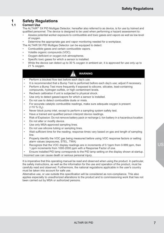
1 Safety Regulations1.1 Correct Use
The ALTAIR 5X PID Multigas Detector, hereafter also referred to as device, is for use by trained and qualified personnel. The device is designed to be used when performing a hazard assessment to:- Assess potential worker exposure to combustible and toxic gases and vapors as well as low level
of oxygen.- Determine the appropriate gas and vapor monitoring needed for a workplace.The ALTAIR 5X PID Multigas Detector can be equipped to detect:- Combustible gases and certain combustible vapors.- Volatile organic compounds (VOC).- Oxygen-deficient or oxygen-rich atmospheres.- Specific toxic gases for which a sensor is installed.- While the device can detect up to 30 % oxygen in ambient air, it is approved for use only up to
21 % oxygen.
It is imperative that this operating manual be read and observed when using the product. In particular, the safety instructions, as well as the information for the use and operation of the product, must be carefully read and observed. Furthermore, the national regulations applicable in the user's country must be taken into account for safe use.Alternative use, or use outside this specification will be considered as non-compliance. This also applies especially to unauthorized alterations to the product and to commissioning work that has not been carried out by MSA or authorized persons.
WARNING
- Perform a blocked flow test before each day's use.- It is recommended that a Bump Test is performed before each day's use; adjust if necessary.- Perform a Bump Test more frequently if exposed to silicone, silicates, lead-containing
compounds, hydrogen sulfide, or high contaminant levels.- Recheck calibration if unit is subjected to physical shock.- Use only to detect gases/vapors for which a sensor is installed.- Do not use to detect combustible dusts or mists.- For accurate catalytic combustible readings, make sure adequate oxygen is present
(>10 % O2).- Never block pump inlet, except to perform a sampling system safety test.- Have a trained and qualified person interpret device readings.- Risk of Explosion: Do not remove battery pack or recharge Li Ion battery in a hazardous location.- Do not alter or modify device.- Use only MSA-approved sampling lines.- Do not use silicone tubing or sampling lines.- Wait sufficient time for the reading; response times vary based on gas and length of sampling
line.- Properly identify the VOC gas being measured before using VOC response factors or setting
alarm values (exposures, STEL, TWA)- Recognize that the VOC display readings are in increments of 0.1ppm from 0-999 ppm, then
1 ppm increments from 1000-2000 ppm with a Response Factor of one.- Ensure installed PID lamp corresponds to the PID lamp setting on the display shown at startup.Incorrect use can cause death or serious personal injury.
ALTAIR 5X PID 8
Safety Regulations
US
1.2 Liability InformationMSA accepts no liability in cases where the product has been used inappropriately or not as intended. The selection and use of this product must be under the direction of a qualified safety professional who has carefully evaluated the specific hazards of the jobsite where it will be used and who is completely familiar with the product and its limitations. The selection and use of this product and its incorporation into the safety scheme of the jobsite is the exclusive responsibility of the employer.Product liability claims, warranties also as guarantees made by MSA with respect to the product are voided, if it is not used, serviced or maintained in accordance with the instructions in this manual.
1.3 Safety and Precautionary Measures
- Check function (see chapter 4.8) each day before use. MSA recommends carrying out a routine inspection prior to each day's use.
- It is recommended that a Bump Test is performed before each day's use (see chapter 4.9) to verify proper device operation. The device must pass the bump test. If it fails the test, perform a calibration (see chapter 4.10) before using the device.
- The ALTAIR 5X PID Detector is designed to detect gases and vapors in air only.- Bluetooth Operation is dependent upon signal availability of the wireless service(s) necessary to
maintain the communication link. Loss of wireless signal will prevent communication of alarms and other information to linked devices. Take appropriate precautions in the event a loss of wireless signal occurs.
Perform a Bump Test more frequently if the device is subjected to physical shock or high levels of contaminants. Also, check calibration more frequently if the tested atmosphere contains the following materials, which may desensitize the combustible gas sensor and/or VOC sensor (PID) and reduce its readings:
- The minimum concentration of a combustible gas in air that can ignite is defined as the Lower Explosive Limit (LEL). A combustible gas reading of XXX indicates the atmosphere is above 100 % LEL, and an explosion hazard exists. Move away from hazardous area immediately.
- Do not use the device to test for combustible or toxic gases in the following atmospheres as this may result in erroneous readings:
WARNING
Carefully review the following safety limitations and precautions before placing this device in service.Incorrect use can cause death or serious personal injury.
WARNING
It is very important to have an understanding of PID basics when changing PID settings. Failure to properly identify the VOC gas being measured and/or failures to select the correct Response Factor alarm values (exposure, STEL, TWA) that match the desired Response Factor and/or the correct lamp will result in erroneous readings or erroneous alarm limits that could cause death or serious personal injury.
- Organic silicones- Silicates- Lead-containing compounds- Sulfur compound exposures over 200 ppm or exposures over 50 ppm for one minute- High concentration of VOC gas may affect CO sensor performance
- Oxygen-deficient or oxygen-rich atmospheres- Reducing atmospheres- Furnace stacks- Inert environments- Atmospheres containing combustible airborne mists/dusts.
ALTAIR 5X PID 9
Safety Regulations
US
- Do not use the ALTAIR 5X PID Multigas Detector to test for combustible gases in atmospheres containing vapors from liquids with a high flash point (above 38 °C, 100 °F) as this may result in erroneously low readings.
- Allow sufficient time for device to display accurate reading. Response times vary based on the type of sensor being utilized (→ chapter 6.2). Allow a minimum of 1 second per foot (3 seconds per meter) of sample line to allow the sample to be drawn through the sensors.
- Sampling lines made from 0.062 inch (1.57 mm) inner diameter tubing provide fast transport times to the device; however, they must be limited to 50 feet (15 m) in length.
- Sampling of reactive toxic gases (Cl2, ClO2, NH3) must only be done with the reactive gas sample line and probe kits listed in chapter 9.
- All device readings and information must be interpreted by someone trained and qualified in inter-preting device readings in relation to the specific environment, industrial practice and exposure limitations.
Observe Proper Battery MaintenanceUse only battery chargers made available by MSA for use with this device; other chargers may damage the battery pack and the device. Dispose of in accordance with local health and safety regulations.
Be Aware of Environmental ConditionsA number of environmental factors may affect the sensor readings, including changes in pressure, humidity and temperature. Pressure and humidity changes also affect the amount of oxygen actually present in the atmosphere.
Be Aware of the Procedures for Handling Electrostatically Sensitive ElectronicsThe device contains electrostatically sensitive components. Do not open or repair the device without using appropriate electrostatic discharge (ESD) protection. The warranty does not cover damage caused by electrostatic discharges.
This Class A digital apparatus complies with Canadian ICES-003.
Be Aware of the Warranty RegulationsThe warranties made by Mine Safety Appliances Company with respect to the product are voided if the product is not used and maintained in accordance with the instructions in this manual. Please protect yourself and others by following them. We encourage our customers to write or call regarding this equipment prior to use or for any additional information relative to use or service.
Be Aware of the Product RegulationsFollow all relevant national regulations applicable in the country of use.
This equipment has been tested and found to comply with the limits for a Class A digital device, pursuant to part 15 of the FCC Rules. These limits are designed to provide reasonable protection against harmful interference when the equipment is operated in a commercial environment. This equipment generates, uses, and can radiate radio frequency energy and, if not installed and used in accordance with the instruction manual, may cause harmful interference to radio communications. Operation of this equipment in a residential area is likely to cause harmful interference in which case the user will be required to correct the interference at his own expense.This device complies with part 15 of the FCC Rules. Operation is subject to the following conditions: (1) This device may not cause harmful interference, and (2) this device must accept any interference received, including any interference that may cause undesired operation.
WARNING
This is a class A product in accordance with CISPR 22. In a domestic environment, this product may cause radio interference, in which case the user may be required to take adequate measures.
ALTAIR 5X PID 10
Safety Regulations
US
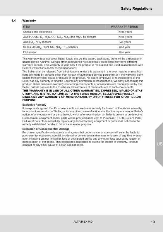
1.4 Warranty
This warranty does not cover filters, fuses, etc. As the battery pack ages, there will be a reduction in usable device run time. Certain other accessories not specifically listed here may have different warranty periods. This warranty is valid only if the product is maintained and used in accordance with Seller's instructions and/or recommendations. The Seller shall be released from all obligations under this warranty in the event repairs or modifica-tions are made by persons other than its own or authorized service personnel or if the warranty claim results from physical abuse or misuse of the product. No agent, employee or representative of the Seller has any authority to bind the Seller to any affirmation, representation or warranty concerning this product. Seller makes no warranty concerning components or accessories not manufactured by the Seller, but will pass on to the Purchaser all warranties of manufacturers of such components. THIS WARRANTY IS IN LIEU OF ALL OTHER WARRANTIES, EXPRESSED, IMPLIED OR STAT-UTORY, AND IS STRICTLY LIMITED TO THE TERMS HEREOF. SELLER SPECIFICALLY DISCLAIMS ANY WARRANTY OF MERCHANTABILITY OR OF FITNESS FOR A PARTICULAR PURPOSE.
Exclusive RemedyIt is expressly agreed that Purchaser's sole and exclusive remedy for breach of the above warranty, for any tortious conduct of Seller, or for any other cause of action, shall be the replacement at Seller's option, of any equipment or parts thereof, which after examination by Seller is proven to be defective. Replacement equipment and/or parts will be provided at no cost to Purchaser, F.O.B. Seller's Plant. Failure of Seller to successfully replace any nonconforming equipment or parts shall not cause the remedy established hereby to fail of its essential purpose.
Exclusion of Consequential DamagePurchaser specifically understands and agrees that under no circumstances will seller be liable to purchaser for economic, special, incidental or consequential damages or losses of any kind whatso-ever, including but not limited to, loss of anticipated profits and any other loss caused by reason of nonoperation of the goods. This exclusion is applicable to claims for breach of warranty, tortious conduct or any other cause of action against seller.
ITEM WARRANTY PERIOD
Chassis and electronics Three years
XCell COMB, O2, H2S, CO, SO2, NO2, and MSA IR sensors Three years
XCell Cl2, NH3 sensors Two years
Series 20 ClO2, HCN, NO, NO2, PH3 sensors One year
PID sensor One year
ALTAIR 5X PID 11
PID Theory and Definitions
US
2 PID Theory and DefinitionsTo support the safe and effective operation of the ALTAIR 5X PID, MSA believes operators should have a working knowledge of how the device functions, not just how to make it work. The information presented in this section supplements the hands-on operational instruction provided in the rest of the manual for the PID.
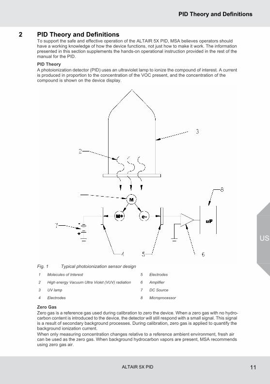
PID TheoryA photoionization detector (PID) uses an ultraviolet lamp to ionize the compound of interest. A current is produced in proportion to the concentration of the VOC present, and the concentration of the compound is shown on the device display.
Fig. 1 Typical photoionization sensor design
Zero GasZero gas is a reference gas used during calibration to zero the device. When a zero gas with no hydro-carbon content is introduced to the device, the detector will still respond with a small signal. This signal is a result of secondary background processes. During calibration, zero gas is applied to quantify the background ionization current.When only measuring concentration changes relative to a reference ambient environment, fresh air can be used as the zero gas. When background hydrocarbon vapors are present, MSA recommends using zero gas air.
1 Molecules of Interest 5 Electrodes
2 High energy Vacuum Ultra Violet (VUV) radiation 6 Amplifier
3 UV lamp 7 DC Source
4 Electrodes 8 Microprocessor
ALTAIR 5X PID 12
PID Theory and Definitions
US
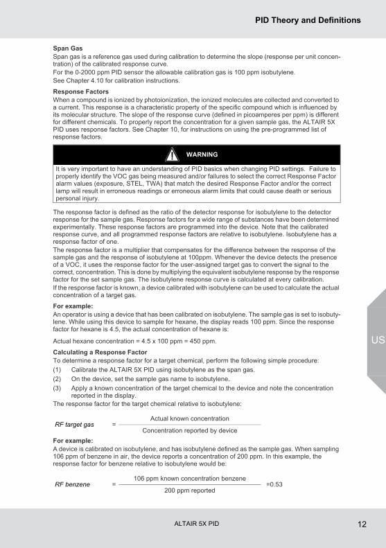
Span GasSpan gas is a reference gas used during calibration to determine the slope (response per unit concen-tration) of the calibrated response curve.For the 0-2000 ppm PID sensor the allowable calibration gas is 100 ppm isobutylene. See Chapter 4.10 for calibration instructions.
Response FactorsWhen a compound is ionized by photoionization, the ionized molecules are collected and converted to a current. This response is a characteristic property of the specific compound which is influenced by its molecular structure. The slope of the response curve (defined in picoamperes per ppm) is different for different chemicals. To properly report the concentration for a given sample gas, the ALTAIR 5X PID uses response factors. See Chapter 10, for instructions on using the pre-programmed list of response factors.
The response factor is defined as the ratio of the detector response for isobutylene to the detector response for the sample gas. Response factors for a wide range of substances have been determined experimentally. These response factors are programmed into the device. Note that the calibrated response curve, and all programmed response factors are relative to isobutylene. Isobutylene has a response factor of one.The response factor is a multiplier that compensates for the difference between the response of the sample gas and the response of isobutylene at 100ppm. Whenever the device detects the presence of a VOC, it uses the response factor for the user-assigned target gas to convert the signal to the correct, concentration. This is done by multiplying the equivalent isobutylene response by the response factor for the set sample gas. The isobutylene response curve is calculated at every calibration. If the response factor is known, a device calibrated with isobutylene can be used to calculate the actual concentration of a target gas.
For example:An operator is using a device that has been calibrated on isobutylene. The sample gas is set to isobuty-lene. While using this device to sample for hexane, the display reads 100 ppm. Since the response factor for hexane is 4.5, the actual concentration of hexane is:
Actual hexane concentration = 4.5 x 100 ppm = 450 ppm.
Calculating a Response FactorTo determine a response factor for a target chemical, perform the following simple procedure:
(1) Calibrate the ALTAIR 5X PID using isobutylene as the span gas.
(2) On the device, set the sample gas name to isobutylene.
(3) Apply a known concentration of the target chemical to the device and note the concentration reported in the display.
The response factor for the target chemical relative to isobutylene:
For example:A device is calibrated on isobutylene, and has isobutylene defined as the sample gas. When sampling 106 ppm of benzene in air, the device reports a concentration of 200 ppm. In this example, the response factor for benzene relative to isobutylene would be:
WARNING
It is very important to have an understanding of PID basics when changing PID settings. Failure to properly identify the VOC gas being measured and/or failures to select the correct Response Factor alarm values (exposure, STEL, TWA) that match the desired Response Factor and/or the correct lamp will result in erroneous readings or erroneous alarm limits that could cause death or serious personal injury.
RF target gas =Actual known concentration
Concentration reported by device
RF benzene =106 ppm known concentration benzene
=0.53200 ppm reported

ALTAIR 5X PID 13
PID Theory and Definitions
US
When surveying, if benzene is selected as the sample gas in the Response Factor page, 0.53 will be used by the device as a response factor. The device will use this response factor to automatically correct the displayed concentration into PPM benzene.A target gas with a response factor between zero and one implies that the device has a higher detector response for that gas when compared to isobutylene. If the response factor is greater than one, the device has a lower detector response for this gas when compared to isobutylene.
WARNING
It is very important to select the correct lamp setting during PID setup since PID response factors for a target chemical relative to isobutylene are different depending on what energy PID lamp is installed. See Chapter 4.5 for setup instructions. Failure to follow this warning can result in inaccurate readings that could lead to serious injury or death.
ALTAIR 5X PID 14
Description
US
3 Description3.1 Overview
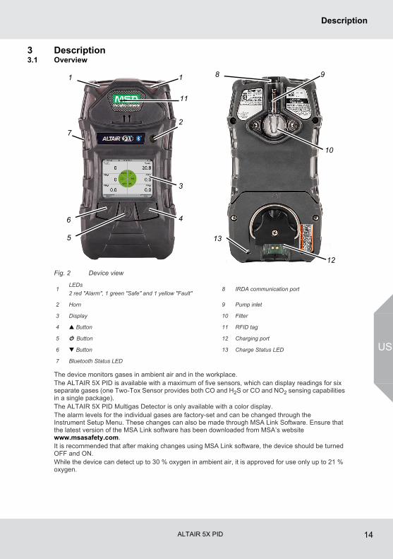
Fig. 2 Device view
The device monitors gases in ambient air and in the workplace.The ALTAIR 5X PID is available with a maximum of five sensors, which can display readings for six separate gases (one Two-Tox Sensor provides both CO and H2S or CO and NO2 sensing capabilities in a single package).The ALTAIR 5X PID Multigas Detector is only available with a color display.The alarm levels for the individual gases are factory-set and can be changed through the Instrument Setup Menu. These changes can also be made through MSA Link Software. Ensure that the latest version of the MSA Link software has been downloaded from MSA’s website www.msasafety.com.It is recommended that after making changes using MSA Link software, the device should be turned OFF and ON.While the device can detect up to 30 % oxygen in ambient air, it is approved for use only up to 21 % oxygen.
1LEDs
2 red "Alarm", 1 green "Safe" and 1 yellow "Fault"8 IRDA communication port
2 Horn 9 Pump inlet
3 Display 10 Filter
4 Button 11 RFID tag
5 q Button 12 Charging port
6 Button 13 Charge Status LED
7 Bluetooth Status LED
1 1
2
3
46
5
7
11
8 9
10
12
13
ALTAIR 5X PID 15
Description
US
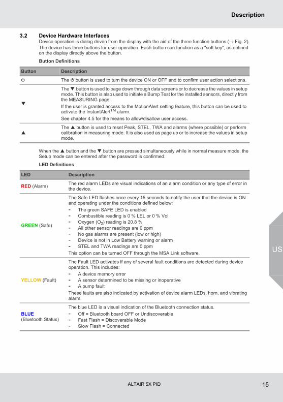
3.2 Device Hardware InterfacesDevice operation is dialog driven from the display with the aid of the three function buttons (→ Fig. 2).The device has three buttons for user operation. Each button can function as a "soft key", as defined on the display directly above the button.
Button Definitions
When the button and the button are pressed simultaneously while in normal measure mode, the Setup mode can be entered after the password is confirmed.
LED Definitions
Button Description
q The q button is used to turn the device ON or OFF and to confirm user action selections.
The button is used to page down through data screens or to decrease the values in setup mode. This button is also used to initiate a Bump Test for the installed sensors, directly from the MEASURING page.
If the user is granted access to the MotionAlert setting feature, this button can be used to activate the InstantAlertTM alarm.
See chapter 4.5 for the means to allow/disallow user access.
The button is used to reset Peak, STEL, TWA and alarms (where possible) or perform calibration in measuring mode. It is also used as page up or to increase the values in setup mode.
LED Description
RED (Alarm)The red alarm LEDs are visual indications of an alarm condition or any type of error in the device.
GREEN (Safe)
The Safe LED flashes once every 15 seconds to notify the user that the device is ON and operating under the conditions defined below:
- The green SAFE LED is enabled- Combustible reading is 0 % LEL or 0 % Vol- Oxygen (O2) reading is 20.8 %- All other sensor readings are 0 ppm- No gas alarms are present (low or high)- Device is not in Low Battery warning or alarm- STEL and TWA readings are 0 ppm
This option can be turned OFF through the MSA Link software.
YELLOW (Fault)
The Fault LED activates if any of several fault conditions are detected during device operation. This includes:
- A device memory error- A sensor determined to be missing or inoperative- A pump fault
These faults are also indicated by activation of device alarm LEDs, horn, and vibrating alarm.
BLUE (Bluetooth Status)
The blue LED is a visual indication of the Bluetooth connection status.
- Off = Bluetooth board OFF or Undiscoverable- Fast Flash = Discoverable Mode- Slow Flash = Connected
ALTAIR 5X PID 16
Description
US
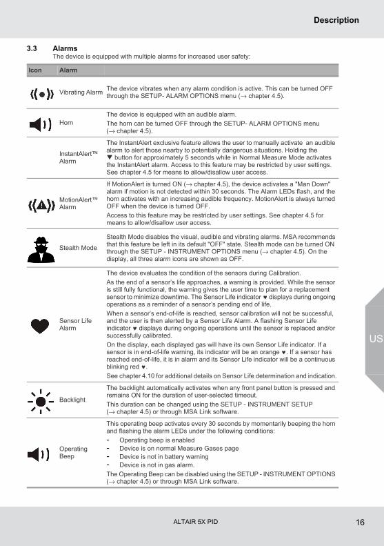
3.3 AlarmsThe device is equipped with multiple alarms for increased user safety:
Icon Alarm
Vibrating AlarmThe device vibrates when any alarm condition is active. This can be turned OFF through the SETUP- ALARM OPTIONS menu (→ chapter 4.5).
HornThe device is equipped with an audible alarm.
The horn can be turned OFF through the SETUP- ALARM OPTIONS menu (→ chapter 4.5).
InstantAlert™ Alarm
The InstantAlert exclusive feature allows the user to manually activate an audible alarm to alert those nearby to potentially dangerous situations. Holding the button for approximately 5 seconds while in Normal Measure Mode activates the InstantAlert alarm. Access to this feature may be restricted by user settings. See chapter 4.5 for means to allow/disallow user access.
MotionAlert™ Alarm
If MotionAlert is turned ON (→ chapter 4.5), the device activates a "Man Down" alarm if motion is not detected within 30 seconds. The Alarm LEDs flash, and the horn activates with an increasing audible frequency. MotionAlert is always turned OFF when the device is turned OFF.
Access to this feature may be restricted by user settings. See chapter 4.5 for means to allow/disallow user access.
Stealth Mode
Stealth Mode disables the visual, audible and vibrating alarms. MSA recommends that this feature be left in its default "OFF" state. Stealth mode can be turned ON through the SETUP - INSTRUMENT OPTIONS menu (→ chapter 4.5). On the display, all three alarm icons are shown as OFF.
Sensor Life Alarm
The device evaluates the condition of the sensors during Calibration.
As the end of a sensor’s life approaches, a warning is provided. While the sensor is still fully functional, the warning gives the user time to plan for a replacement sensor to minimize downtime. The Sensor Life indicator ♥ displays during ongoing operations as a reminder of a sensor’s pending end of life.
When a sensor’s end-of-life is reached, sensor calibration will not be successful, and the user is then alerted by a Sensor Life Alarm. A flashing Sensor Life indicator ♥ displays during ongoing operations until the sensor is replaced and/or successfully calibrated.
On the display, each displayed gas will have its own Sensor Life indicator. If a sensor is in end-of-life warning, its indicator will be an orange ♥. If a sensor has reached end-of-life, it is in alarm and its Sensor Life indicator will be a continuous blinking red ♥.
See chapter 4.10 for additional details on Sensor Life determination and indication.
Backlight
The backlight automatically activates when any front panel button is pressed and remains ON for the duration of user-selected timeout.
This duration can be changed using the SETUP - INSTRUMENT SETUP (→ chapter 4.5) or through MSA Link software.
Operating Beep
This operating beep activates every 30 seconds by momentarily beeping the horn and flashing the alarm LEDs under the following conditions:
- Operating beep is enabled- Device is on normal Measure Gases page- Device is not in battery warning- Device is not in gas alarm.
The Operating Beep can be disabled using the SETUP - INSTRUMENT OPTIONS (→ chapter 4.5) or through MSA Link software.
ALTAIR 5X PID 17
Description
US
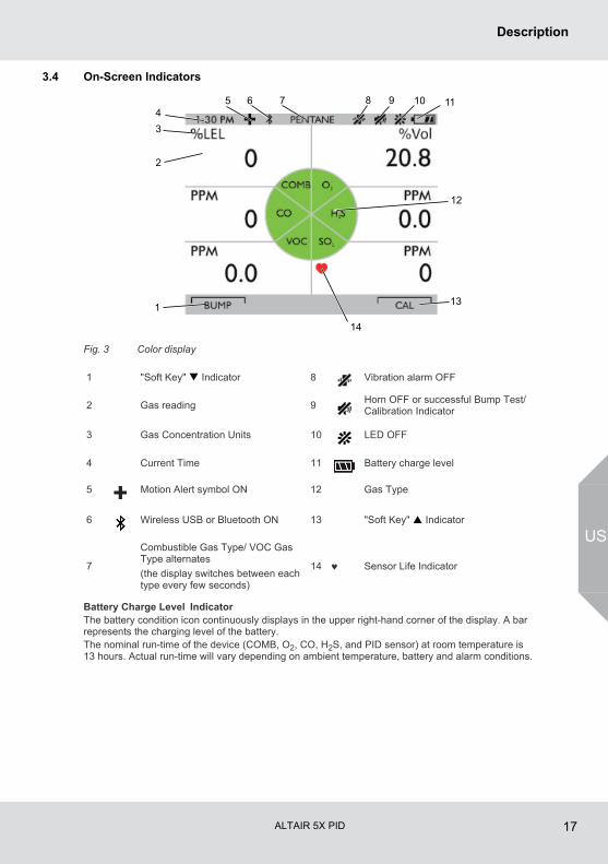
3.4 On-Screen Indicators
Fig. 3 Color display
Battery Charge Level IndicatorThe battery condition icon continuously displays in the upper right-hand corner of the display. A bar represents the charging level of the battery.The nominal run-time of the device (COMB, O2, CO, H2S, and PID sensor) at room temperature is 13 hours. Actual run-time will vary depending on ambient temperature, battery and alarm conditions.
1 "Soft Key" Indicator 8 Vibration alarm OFF
2 Gas reading 9Horn OFF or successful Bump Test/Calibration Indicator
3 Gas Concentration Units 10 LED OFF
4 Current Time 11 Battery charge level
5 Motion Alert symbol ON 12 Gas Type
6 Wireless USB or Bluetooth ON 13 "Soft Key" Indicator
7
Combustible Gas Type/ VOC Gas Type alternates
(the display switches between each type every few seconds)
14 ♥ Sensor Life Indicator
1
2
34
6 7 8 9 10
13
14
12
115
ALTAIR 5X PID 18
Description
US
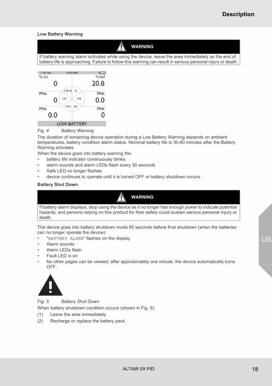
Low Battery Warning
Fig. 4 Battery Warning
The duration of remaining device operation during a Low Battery Warning depends on ambient temperatures, battery condition alarm status. Nominal battery life is 30-60 minutes after the Battery Warning activates.When the device goes into battery warning the:- battery life indicator continuously blinks- alarm sounds and alarm LEDs flash every 30 seconds- Safe LED no longer flashes- device continues to operate until it is turned OFF or battery shutdown occurs.
Battery Shut Down
The device goes into battery shutdown mode 60 seconds before final shutdown (when the batteries can no longer operate the device):- "BATTERY ALARM” flashes on the display- Alarm sounds- Alarm LEDs flash- Fault LED is on- No other pages can be viewed; after approximately one minute, the device automatically turns
OFF.
Fig. 5 Battery Shut Down
When battery shutdown condition occurs (shown in Fig. 5):
(1) Leave the area immediately.
(2) Recharge or replace the battery pack.
WARNING
If battery warning alarm activates while using the device, leave the area immediately as the end of battery life is approaching. Failure to follow this warning can result in serious personal injury or death.
WARNING
If battery alarm displays, stop using the device as it no longer has enough power to indicate potential hazards, and persons relying on this product for their safety could sustain serious personal injury or death.
ALTAIR 5X PID 19
Description
US
Battery Charging
The charger is capable of charging a completely depleted pack in less than six hours in normal, room-temperature environments.
- Minimum and maximum ambient temperature to charge the device is 10 °C (50 °F) and 35 °C (95 °F), respectively.
- For best results, charge the device at room temperature 23 °C (73 °F).
To Charge the Device- Firmly insert the charger connector into the charge port on the back of the device.- An LED in the battery pack is used to indicate on the charge status.
Red = charging, Green = charged, yellow = fault
- If a problem is detected during charging (LED turns yellow):
Disconnect the charger momentarily to reset the charge cycle.
- The battery pack may be charged separately from the device.- During periods of non-use, the charger may remain connected to the device/battery pack.
WARNING
Risk of explosion: Do not recharge device in hazardous area.
NOTICEUse of any charger, other than the charger supplied with the device, may damage or improperly charge the batteries.
For users in Australia/ New Zealand: The charge cradle is a Class A product. In a domestic environment, this product may cause radio interference, in which case, the user may be required to take adequate measures.
Allow very hot or cold devices to stabilize for one hour at room temperature before attempting to charge.
The charger must be disconnected for the device to operate.
ALTAIR 5X PID 20
Description
US
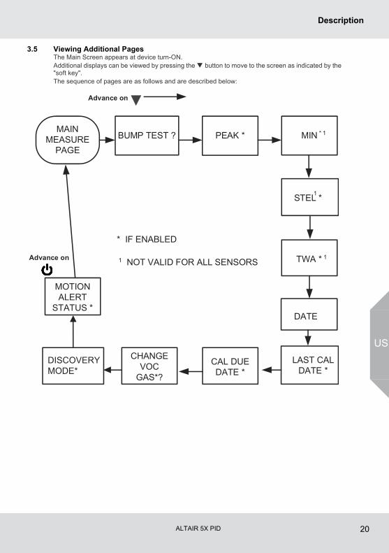
3.5 Viewing Additional PagesThe Main Screen appears at device turn-ON.Additional displays can be viewed by pressing the button to move to the screen as indicated by the "soft key".The sequence of pages are as follows and are described below:
PEAK * MIN
STEL * 1
TWA * 1
BUMP TEST ?
DATE
LAST CALDATE *
CAL DUEDATE *
MOTIONALERT
STATUS *
MAINMEASURE
PAGE
Advance on
Advance on
* IF ENABLED
1 NOT VALID FOR ALL SENSORS
* 1
DISCOVERYMODE*
CHANGEVOC
GAS*?
ALTAIR 5X PID 21
Description
US
Bump Test (BUMP page)This page allows the user to perform an automated Bump Test on the device. To perform the test, the (YES) button is pressed. See chapter 4.9 for details on performing the Bump Test. If the button is pressed, the Bump Test is not performed, and the display shows the next page in the sequence (PEAK).If the button is pressed, the Bump Test is not performed, and the display reverts back to the normal MEASURE page.
This page shows the highest levels of gas recorded by the device since turn-ON or since peak readings were reset.To reset the peak readings:
(1) Access the PEAK page.
(2) Press the button.
This page shows the lowest level of oxygen recorded by the device since turn-ON or since the MIN reading was reset. It is only shown if an oxygen sensor is installed and enabled.To reset the MIN reading:
(1) Access the MIN page.
(2) Press the button.
This page shows the average exposure over a 15-minute period.When the amount of gas detected by device is greater than the STEL limit:- Alarm sounds, alarm lights flash.- Alarm LEDs flash- “STEL ALARM” message flashes.
To reset the STEL:
(1) Access the STEL page.
(2) Press the button.The STEL alarm is calculated over a 15-minute exposure.STEL calculation examples:Assume the device has been running for at least 15 minutes:
Peak Readings (PEAK page)
This page can be de-activated through MSA Link software.
Minimum Readings (MIN page)
Short Term Exposure Limits (STEL page)
WARNING
If the STEL alarm activates, leave the contaminated area immediately; the ambient gas concentra-tion has reached the preset STEL alarm level. Failure to follow this warning will cause over-exposure to toxic gases and persons relying on this product for their safety could sustain serious personal injury or death.
ALTAIR 5X PID 22
Description
US
15 minute exposure of 35 ppm:
10 minute exposure of 35 ppm and 5 minutes exposure of 15 ppm:
This page shows the average exposure over 8 hours since the device was turned ON or since the TWA reading was reset. When the amount of gas detected is greater than the eight-hour TWA limit:- Alarm sounds- Alarm LEDs flash- “TWA ALARM” message flashes.To reset the TWA Readings:
(1) Access the TWA page.
(2) Press the button.The TWA alarm is calculated over an eight-hour exposure.
(15 minutes x 35 ppm) = 35 ppm
15 minutes
(10 minutes x 35 ppm) + (5 minutes x 5 ppm) = 25 ppm
15 minutes
This page can be de-activated through MSA Link software.
Time Weighted Average (TWA page)
WARNING
If the TWA alarm activates, leave the contaminated area immediately; the ambient gas concentration has reached the preset TWA alarm level. Failure to follow this warning will cause over-exposure to toxic gases and persons relying on this product for their safety could sustain serious personal injury or death.
ALTAIR 5X PID 23
Description
US
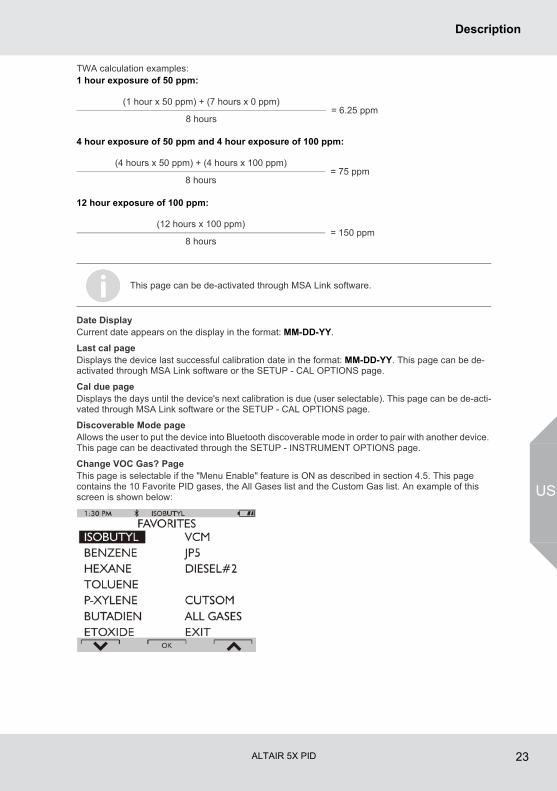
TWA calculation examples:1 hour exposure of 50 ppm:
4 hour exposure of 50 ppm and 4 hour exposure of 100 ppm:
12 hour exposure of 100 ppm:
Date DisplayCurrent date appears on the display in the format: MM-DD-YY.
Last cal pageDisplays the device last successful calibration date in the format: MM-DD-YY. This page can be de-activated through MSA Link software or the SETUP - CAL OPTIONS page.
Cal due pageDisplays the days until the device's next calibration is due (user selectable). This page can be de-acti-vated through MSA Link software or the SETUP - CAL OPTIONS page.
Discoverable Mode page Allows the user to put the device into Bluetooth discoverable mode in order to pair with another device. This page can be deactivated through the SETUP - INSTRUMENT OPTIONS page.
Change VOC Gas? PageThis page is selectable if the "Menu Enable" feature is ON as described in section 4.5. This page contains the 10 Favorite PID gases, the All Gases list and the Custom Gas list. An example of this screen is shown below:
(1 hour x 50 ppm) + (7 hours x 0 ppm) = 6.25 ppm
8 hours
(4 hours x 50 ppm) + (4 hours x 100 ppm) = 75 ppm
8 hours
(12 hours x 100 ppm) = 150 ppm
8 hours
This page can be de-activated through MSA Link software.
ALTAIR 5X PID 24
Description
US
Motion Alert Activation PageWhen the MotionAlert feature is active, the + symbol appears. The device enters pre-alarm when no motion is detected for 20 seconds. This condition can be cleared by moving the device. MotionAlert is turned OFF each time the device is powered OFF. After 30 seconds of no motion, the full MotionAlert alarm is triggered. This alarm can only be cleared by pressing the button. This page displays if it was selected in Setup Mode. To activate or deactivate the MotionAlert feature, press the button while the MOTIONALERT ACTIVATION page is displayed.
3.6 Sensor Missing AlarmEnabled PID and XCell sensors are continuously monitored for proper function. If, during operation, the PID or an XCell sensor is detected as failed or disconnected, this alarm message appears.- "SENSOR MISSING" flashes on the display.- The problematic sensor is indicated.- The alarm sounds and the Fault and Alarm LEDs flash.- The alarm can be silenced by pressing the button; no other pages can be viewed.
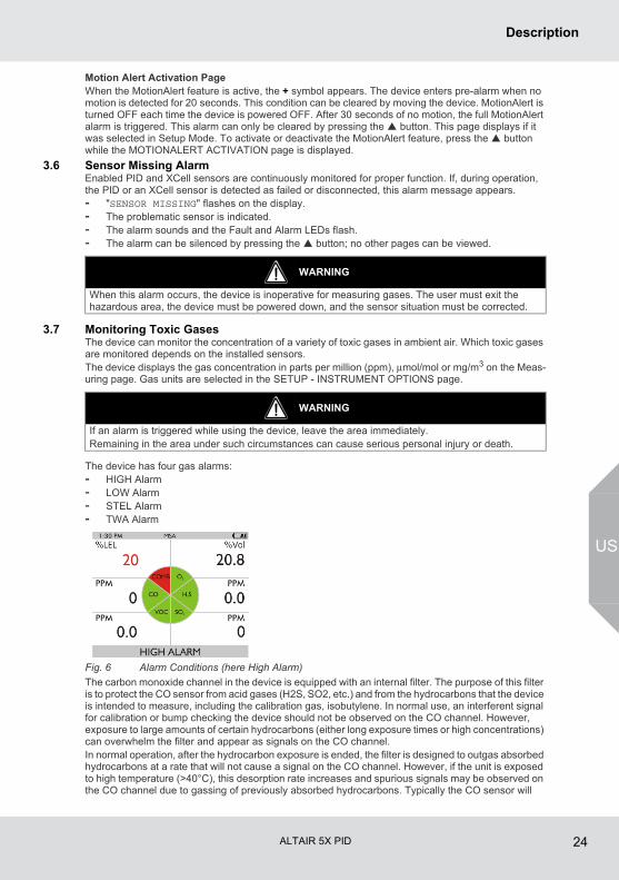
3.7 Monitoring Toxic GasesThe device can monitor the concentration of a variety of toxic gases in ambient air. Which toxic gases are monitored depends on the installed sensors. The device displays the gas concentration in parts per million (ppm), μmol/mol or mg/m3 on the Meas-uring page. Gas units are selected in the SETUP - INSTRUMENT OPTIONS page.
The device has four gas alarms:- HIGH Alarm- LOW Alarm- STEL Alarm- TWA Alarm
Fig. 6 Alarm Conditions (here High Alarm)
The carbon monoxide channel in the device is equipped with an internal filter. The purpose of this filter is to protect the CO sensor from acid gases (H2S, SO2, etc.) and from the hydrocarbons that the device is intended to measure, including the calibration gas, isobutylene. In normal use, an interferent signal for calibration or bump checking the device should not be observed on the CO channel. However, exposure to large amounts of certain hydrocarbons (either long exposure times or high concentrations) can overwhelm the filter and appear as signals on the CO channel. In normal operation, after the hydrocarbon exposure is ended, the filter is designed to outgas absorbed hydrocarbons at a rate that will not cause a signal on the CO channel. However, if the unit is exposed to high temperature (>40°C), this desorption rate increases and spurious signals may be observed on the CO channel due to gassing of previously absorbed hydrocarbons. Typically the CO sensor will
WARNING
When this alarm occurs, the device is inoperative for measuring gases. The user must exit the hazardous area, the device must be powered down, and the sensor situation must be corrected.
WARNING
If an alarm is triggered while using the device, leave the area immediately.Remaining in the area under such circumstances can cause serious personal injury or death.
ALTAIR 5X PID 25
Description
US
recover within 24 hours but extremely high exposures can extend this time. After the recovery period if the CO sensor can no longer be calibrated or shows an elevated reading that cannot be brought to zero with a zero calibration, the CO sensor should be replaced.If the gas concentration reaches or exceeds the alarm set point or the STEL or TWA limits, the:- alarm message displays and flashes in combination with the corresponding gas concentration- backlight turns on- alarm sounds (if active)- alarm LEDs flash (if active)- vibrating alarm triggers (if active)
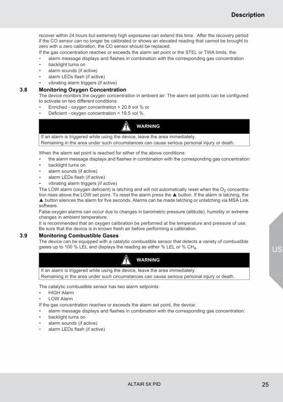
3.8 Monitoring Oxygen ConcentrationThe device monitors the oxygen concentration in ambient air. The alarm set points can be configured to activate on two different conditions:- Enriched - oxygen concentration > 20.8 vol % or - Deficient - oxygen concentration < 19.5 vol %.
When the alarm set point is reached for either of the above conditions:- the alarm message displays and flashes in combination with the corresponding gas concentration- backlight turns on- alarm sounds (if active)- alarm LEDs flash (if active)- vibrating alarm triggers (if active)The LOW alarm (oxygen deficient) is latching and will not automatically reset when the O2 concentra-tion rises above the LOW set point. To reset the alarm press the button. If the alarm is latching, the button silences the alarm for five seconds. Alarms can be made latching or unlatching via MSA Link software.False oxygen alarms can occur due to changes in barometric pressure (altitude), humidity or extreme changes in ambient temperature.It is recommended that an oxygen calibration be performed at the temperature and pressure of use. Be sure that the device is in known fresh air before performing a calibration.
3.9 Monitoring Combustible GasesThe device can be equipped with a catalytic combustible sensor that detects a variety of combustible gases up to 100 % LEL and displays the reading as either % LEL or % CH4.
The catalytic combustible sensor has two alarm setpoints:- HIGH Alarm- LOW AlarmIf the gas concentration reaches or exceeds the alarm set point, the device:- alarm message displays and flashes in combination with the corresponding gas concentration:- backlight turns on- alarm sounds (if active)- alarm LEDs flash (if active)
WARNING
If an alarm is triggered while using the device, leave the area immediately.Remaining in the area under such circumstances can cause serious personal injury or death.
WARNING
If an alarm is triggered while using the device, leave the area immediately.Remaining in the area under such circumstances can cause serious personal injury or death.
ALTAIR 5X PID 26
Description
US
Gas Exposure of 100 % LELWhen gas reading exceeds 100 % of the lower explosive limit (LEL), the device enters a Lock Alarm state and displays “XXX” in place of the actual reading.
The user can clear the LockAlarm state only by turning the device OFF, and then ON again in a fresh air environment. When catalytic combustible gas reading digits appear, the device is available for measuring gases once again.
3.10 Monitoring VOC GasesThe device is equipped with a PID sensor that detects a variety of VOC gases. The device displays the gas concentration in parts per million (ppm), µmol/mol or mg/m3 on the Measuring page.
The device has four gas alarms:- HIGH Alarm- LOW Alarm- STEL Alarm- TWA AlarmIf the gas concentration reaches or exceeds the alarm set point or the STEL or TWA limits, the:- alarm message displays and flashes in combination with the corresponding gas concentration- backlight turns on- alarm sounds (if active)- alarm LEDs flash (if active)- vibrating alarm triggers (if active)To reset the alarm press the button.False VOC alarms can occur due to changes in barometric pressure (altitude), humidity or extremechanges in ambient temperature. It is recommended that a VOC calibration be performed at the temperature, humidity and pressure of use.Be sure that the device is in known fresh air before performing a calibration. For optimal lamp strike, the PID lamp should be started within the normal temperature range.
WARNING
A catalytic combustible gas reading of "XXX” indicates the atmosphere could be above 100 % LEL and an explosion hazard exists. Move away from contaminated area immediately.
Check your national standard values for 100 % LEL.
WARNING
If an alarm is triggered while using the device, leave the area immediately.Remaining in the area under such circumstances can cause serious personal injury or death.
When the device is calibrated in an dry, air conditioned environment and taken to a high temperature and high humidity outdoor environment, a VOC Low or High alarm may be triggered by this sudden change. It is recommended that the PID sensors be cleaned prior to this transition to avoid this situation, or to acclimate the sensor to the outdoor conditions in a known safe area.
ALTAIR 5X PID 27
Description
US
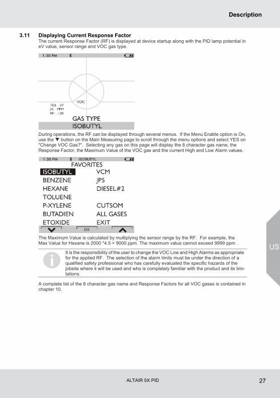
3.11 Displaying Current Response FactorThe current Response Factor (RF) is displayed at device startup along with the PID lamp potential in eV value, sensor range and VOC gas type.
During operations, the RF can be displayed through several menus. If the Menu Enable option is On, use the button on the Main Measuring page to scroll through the menu options and select YES on "Change VOC Gas?". Selecting any gas on this page will display the 8 character gas name, the Response Factor, the Maximum Value of the VOC gas and the current High and Low Alarm values.
The Maximum Value is calculated by multiplying the sensor range by the RF. For example, the Max Value for Hexane is 2000 *4.5 = 9000 ppm. The maximum value cannot exceed 9999 ppm .
A complete list of the 8 character gas name and Response Factors for all VOC gases is contained in chapter 10.
It is the responsibility of the user to change the VOC Low and High Alarms as appropriate for the applied RF. The selection of the alarm limits must be under the direction of a qualified safety professional who has carefully evaluated the specific hazards of the jobsite where it will be used and who is completely familiar with the product and its limi-tations.
ALTAIR 5X PID 28
Operation
US
4 OperationDevice operation is dialog driven from the display with the aid of the three function buttons (→ chapter 3.2).For more information, see the flow charts in chapter 11.
4.1 Environmental FactorsA number of environmental factors may affect the gas sensor readings, including changes in pressure, humidity and temperature. Pressure and humidity changes affect the amount of oxygen actually present in the atmosphere.
Pressure ChangesIf pressure changes rapidly (e.g., stepping through airlock), the oxygen sensor reading may temporarily shift and possibly cause the device to go into alarm. While the percentage of oxygen may remain at or near 20.8 Vol %, the total amount of oxygen present in the atmosphere available for respiration may become a hazard if the overall pressure is reduced by a significant degree.
Humidity ChangesIf humidity changes by any significant degree (e.g., going from a dry, air conditioned environment to outdoor, moisture laden air), oxygen readings can be reduced by up to 0.5 %, due to water vapor in the air displacing oxygen. The oxygen sensor has a special filter to reduce the effects of humidity changes on oxygen readings. This effect will not be noticed immediately, but slowly impacts oxygen readings over several hours.
Temperature ChangesThe sensors have built-in temperature compensation. However, if temperature shifts dramatically, the sensor reading could shift.
Combined Humidity and Temperature ChangesWhen the device is calibrated in an dry, air conditioned environment and taken to a high temperature and high humidity outdoor environment, a VOC Low or High alarm may be triggered by this sudden change. It is recommended that the PID sensors be cleaned prior to this transition to avoid this situa-tion, or to acclimate the sensor to the outdoor conditions in a known safe area.
ALTAIR 5X PID 29
Operation
US
4.2 Turning ON and Fresh Air SetupDevice operation is dialog driven from the display with the aid of the three function buttons (→ chapter 3.2).For more information, see the flow charts in chapter 11.
Turn the device ON with the q button.The device performs a self test:During the self test, the device checks alarm LEDs, audible alarm, vibrating alarm and installed sensors. The device displays: - Startup logo- Software version, device serial number, company name, department and user names- IC / FCC ID Identifier- Sampling system safety testDuring the turn-ON sequence, if a sensor was changed since the previous device operation, the current listing of the installed sensors displays and user interaction is required.
The user must accept the new configuration by pressing the button.
If the current sensor configuration is not accepted, the device alarms and is not usable.
- FCC Identification page- Combustible gas type, and installed sensor indication- VOC gas type, lamp value, detectable range and Response Factor- Alarm setpoints Low Alarm- Alarm setpoints High Alarm- Alarm setpoints STEL Alarm (if enabled)- Alarm setpoints TWA Alarm (if enabled)- Settings for calibration cylinder- Current date- Last calibration date (if enabled)- CAL due date. If the calibration due date is enabled, the message "CAL DUE; X DAYS" appears
on the device display.
- Sensor warm-up period- Fresh Air Setup option (if enabled).The Main Measure Page will appear.The presence of a ♥ indicator on the display means a sensor is approaching or has reached its end-of-life. See chapter 3.3 for details on the Sensor Life Alarm situation.Refer to flowchart in chapter 11.1.
Sampling System Safety TestUpon startup, an alarm (visual, audible and vibrating) is triggered and the customer is prompted to block the pumps/sampling system of the device within 30 seconds.When the device detects a pump flow block, it will display a PASS message. The startup sequence will resume.If the device does not detect a pump flow block, it will display an error message.The device will shut OFF after the customer acknowledges this message by pressing the button.Check your sampling system if this occurs and contact MSA as needed.Users can check the operation of the sampling system any time during operation by blocking the sampling system to generate a pump alarm.
- X = the number of days until a calibration is due, user selectable for 1 to 180 days.
If the number of days until calibration is due reaches 0, an alert occurs and "CAL DUE, NOW" displays.
- Press the button to clear the alert
ALTAIR 5X PID 30
Operation
US
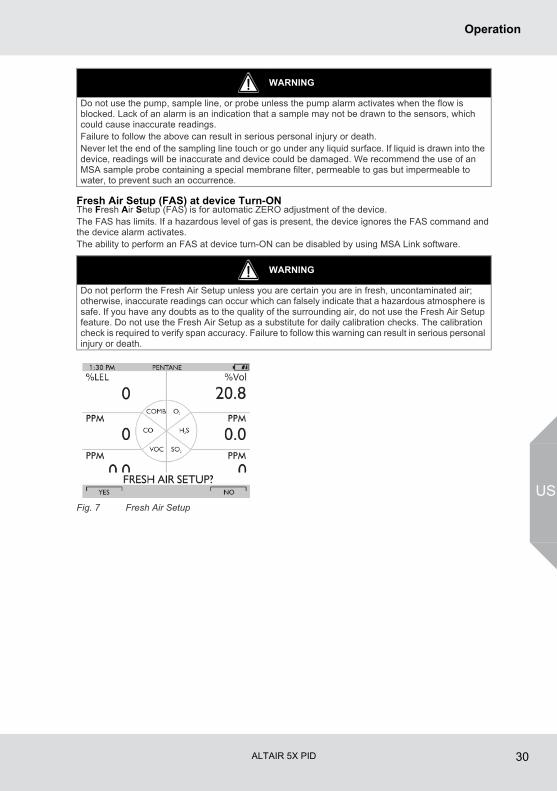
Fresh Air Setup (FAS) at device Turn-ONThe Fresh Air Setup (FAS) is for automatic ZERO adjustment of the device. The FAS has limits. If a hazardous level of gas is present, the device ignores the FAS command and the device alarm activates.The ability to perform an FAS at device turn-ON can be disabled by using MSA Link software.
Fig. 7 Fresh Air Setup
WARNING
Do not use the pump, sample line, or probe unless the pump alarm activates when the flow is blocked. Lack of an alarm is an indication that a sample may not be drawn to the sensors, which could cause inaccurate readings.Failure to follow the above can result in serious personal injury or death.Never let the end of the sampling line touch or go under any liquid surface. If liquid is drawn into the device, readings will be inaccurate and device could be damaged. We recommend the use of an MSA sample probe containing a special membrane filter, permeable to gas but impermeable to water, to prevent such an occurrence.
WARNING
Do not perform the Fresh Air Setup unless you are certain you are in fresh, uncontaminated air; otherwise, inaccurate readings can occur which can falsely indicate that a hazardous atmosphere is safe. If you have any doubts as to the quality of the surrounding air, do not use the Fresh Air Setup feature. Do not use the Fresh Air Setup as a substitute for daily calibration checks. The calibration check is required to verify span accuracy. Failure to follow this warning can result in serious personal injury or death.
ALTAIR 5X PID 31
Operation
US
The device displays a blinking "FRESH AIR SETUP?", prompting the user to perform a Fresh Air Setup:
(1) Press the button to bypass the Fresh Air Setup.
The Fresh Air Setup is skipped and the device goes to the Measuring page (Main page).
(2) Press the button to perform the Fresh Air Setup.
The device starts the FAS sequence and the FAS screen displays.
A progress bar shows the user how much of the FAS has been completed.
At the end of the FAS, the device displays either "FRESH AIR SETUP PASS" or "FRESH AIR SETUP FAIL".
If the FAS fails, perform a zero calibration (→ chapter 4.10).
4.3 Special Consideration for Oxygen SensorUnder the following situations, the oxygen sensor display reading may be suppressed for up to 30 minutes at device turn-ON as a sensor 'cook down' is performed.This could occur if:- the oxygen sensor was just installed- the battery pack was allowed to be deep-discharged- the battery pack was removed from the device.During this time, the oxygen sensor numeric position on the display indicates "PLEASE WAIT". While this message displays, the device cannot respond to a:- Fresh Air Setup- Calibration- Bump Test procedure.When the numeric oxygen reading appears, the FAS, calibration, or Bump Test procedures may be performed.
ALTAIR 5X PID 32
Operation
US
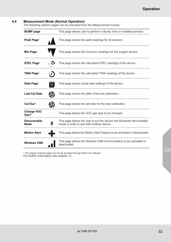
4.4 Measurement Mode (Normal Operation)The following options pages can be executed from the Measurement screen:
* The display of these pages can be de-activated through MSA Link softwareFor further information see chapter 12.
BUMP page This page allows user to perform a Bump Test on installed sensors
Peak Page* This page shows the peak readings for all sensors.
Min Page This page shows the minimum readings for the oxygen sensor.
STEL Page* This page shows the calculated STEL readings of the device.
TWA Page* This page shows the calculated TWA readings of the device.
Date Page This page shows actual date settings of the device.
Last Cal Date This page shows the date of the last calibration.
Cal Due* This page shows the set date for the next calibration.
Change VOC Gas?
This page allows the VOC gas type to be changed
Discoverable Mode
This page allows the user to put the device into Bluetooth discoverable mode in order to pair with another device.
Motion Alert This page allows the Motion Alert Feature to be activated or deactivated.
Wireless USBThis page allows the Wireless USB communication to be activated or deactivated.
ALTAIR 5X PID 33
Operation
US
4.5 Device SetupThe device has provisions to access and modify the following parameters through direct button inter-face:- Calibration Options- Alarm Options- Instrument OptionsThese menus can be accessed only from the measure page by pressing and holding the and buttons simultaneously until you are prompted for a password.The operation is as follows:
(1) Turn the device ON and wait until the measure page appears.
(2) Simultaneously press and hold the and buttons for approximately five seconds.
The default password is "672".
(3) Enter the first digit by pressing the or button and confirm with the q button.
The cursor jumps to the second digit.
(4) Enter the second as well as the third digits.
Incorrect password: device returns to the Main Page.
Correct password: user can enter the Setup mode.
The password can be changed with a PC through the MSA Link software.If the password is forgotten, it can be reset by using MSA Link software. Contact MSA Customer Service for assistance. The following Options are available by pressing the and buttons:- Calibration Options - see chapter 4.5- Alarm Options - see chapter 4.5- Instrument Options - see chapter 4.5
PASSWORD
000
ALTAIR 5X PID 34
Operation
US
Calibration Setup
The Calibration Options menu has provisions to: - modify the calibration cylinder settings (CYLINDER SETUP)- enable/disable calibration due and to set the number of days (CAL DUE OPTIONS)- enable/disable the option to show the last cal date at turn on and (LAST CAL DATE)
When enabled, the date of the last device calibration displays during the turn-ON process.
- enable/disable the option for password protected calibration (CAL PASSWORD)
When enabled, the device setup password must be entered prior to calibration.
Press:- the button go to next page
the button to go previous page
the q button to enter setup.
Setting Calibration Cylinder This option has a dialog similar to the span calibration dialog.The display shows all active sensors.
(1) Press the q button to enter setup.
The screen for the first calibration cylinder displays.
(2) Press
the or button to change the value.
the q button to confirm the setup.
With this confirmation the device automatically moves to the next cylinder setting.
(3) Repeat the sequence for changing the required settings for all necessary gas values.After the last setting is performed, the device returns to the Calibration Options menu.
CALIBRATION OPTIONS
The only allowed calibration gas for the 0-2000 ppm PID sensor is 100 ppm isobutylene balanced in air. Higher concentrations can cause false readings of the CO sensor.
ALTAIR 5X PID 35
Operation
US
Setting Cal Due Options
(1) Press the q button to enter setup.
(2) Press the or button to enable/disable this option.
(3) Press the q button to confirm.
(4) After confirmation the device prompts the user to enter the number of days for the reminder.
(5) Change number of days by pressing the or button.
(6) Press the q button to go to the next menu.
Setting Last Cal Date
(1) Press the q button to enable/disable this option.
(2) Press the button to go to the next page.
(3) Press the button to go to the previous page.
Setting Calibration Password
(1) Press the q button to enable/disable this option.
(2) Press the button to go to the next page.
(3) Press the button to go to the previous page.
Back To Main Menu
(1) Press the q button to go to Device Setup Menu
The Cal Options screen displays
(2) Press the button to go to the next (Alarm options) or the button to exit the Setup menu.Alarm Setup
The Alarm Options Menu allows the user to: - enable/disable the vibrating alarm- enable/disable the audible alarm (horn)- enable/disable the Alarm LEDs - enable/disable the MOTIONALERT SELECTION page.
If disabled, the user cannot change the device MotionAlert setting.
- set Sensor Alarms.Press - the button go to next page
the button to go previous page
the q button to enter setup.
Setting Vibrating AlarmPress the q button to enable/disable this option.
Setting Horn AlarmPress q button to enable/disable this option.
Setting LED AlarmPress q button to enable/disable this option.
ALARM OPTIONS
ALTAIR 5X PID 36
Operation
US
Setting MotionAlert AccessSetting this parameter allows access to the MOTIONALERT page from the MEASURE page.If access is denied here:- the user cannot access the MOTIONALERT page to enable or disable that feature- the InstantAlert feature (chapter 3.3) cannot be activated.
(1) To grant or deny user access to the MOTIONALERT page, use the button to change the indi-cated selection.
User access is:
permitted when the setting indicates ON.
denied when the setting indicates OFF.
(2) The selection is confirmed by pressing either the or button.
Setting Sensor AlarmsThis page allows modifying the preset alarm values of:- LOW Alarm- HIGH Alarm- STEL Alarm- TWA Alarm.
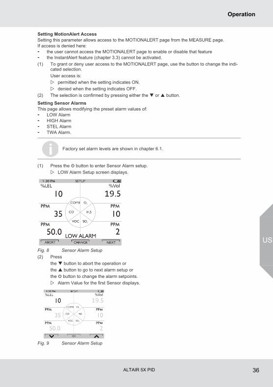
(1) Press the q button to enter Sensor Alarm setup.
LOW Alarm Setup screen displays.
Fig. 8 Sensor Alarm Setup
(2) Press
the button to abort the operation or
the button to go to next alarm setup or
the q button to change the alarm setpoints.
Alarm Value for the first Sensor displays.
Fig. 9 Sensor Alarm Setup
Factory set alarm levels are shown in chapter 6.1.
ALTAIR 5X PID 37
Operation
US
(3) Set values for Sensor Alarm by pressing the or button.
(4) Press the q button to confirm set value.
(5) Repeat setting for all other sensors.
(6) Press the button to return to the Alarm Options menu.
(7) Repeat setting for all other alarm types.
Instrument Options
The Instrument Options menu allows modification of different device options:- Sensor Setup (enable/disable the channel)- Language Setup- Time Date Setup- Datalog Intervals- Stealth Mode- Operating Beep- Backlight Options- VOC Gas Setup- BluetoothPress - the button go to next page
the button to go previous page
the q button to enter setup.
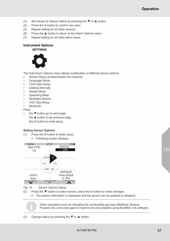
Setting Sensor Options
(1) Press the q button to enter setup.
Following screen displays:
Fig. 10 Sensor Options Setup
(2) Press the button to select sensor, press the q button to make changes.
The sensor information is displayed and the sensor can be enabled or disabled.
(3) Change status by pressing the or button.
SETTINGS
Other operations such as changing the combustible gas type (Methane, Butane, Propane etc.) and units (ppm to mg/m3) are only possible using the MSA Link software.
ALTAIR 5X PID 38
Operation
US
(4) Press the q button to confirm and advance to next screen (next sensor).
(5) Perform the sequence for all other sensors.
After setting up the last sensor the device goes to the next Setup Page.
Language SetupThis option is for setting the language of the device.
(1) Press the q button to enter setup.
(2) Change language by pressing the or button.
(3) Confirm with the q button.
The device goes to the next Setup Page.
Time and Date SetupThis option is for setting the device time and date. The device first prompts to set the time and then it prompts for the date.
(1) Press the q button to enter setup.
(2) Change hours by pressing the or button.
(3) Confirm with the q button.
(4) Change minutes by pressing the or button.
(5) Confirm with the q button.
The device goes to the Set Date Page.
(6) Change month, date and year by pressing the or button and confirming with the q button.
The device goes to the next Setup Page.
(7) Confirm with the q button.
The device goes to the next Setup Page.
Setting Datalog IntervalsThis option is for setting the intervals at which all the readings will be logged.
(1) Press the q button to enter setup.
(2) Change interval by pressing the or button.
(3) Confirm with the q button.
The device goes to the next Setup Page.
Setting Stealth ModeStealth mode disables the visual, audible and vibrating alarms.
(1) Press the q button to change mode (ON/OFF).
(2) Press the button to go to the next page or the button to return to previous page.
Setting Operating Beep
(1) Press the q button to change mode (ON/OFF).
(2) Press the button to go to the next page or the button to return to previous page.
Setting Backlight
(1) Press the q button to enter setup.
Change option by pressing the or button.
(2) Press the q button to enter.
(3) Change timeout by pressing the or button.
(4) Press q button to confirm timeout.
The time can be set up for either regular AM/PM or military time (through MSA Link soft-ware). AM/PM time is the default setting.
ALTAIR 5X PID 39
Operation
US
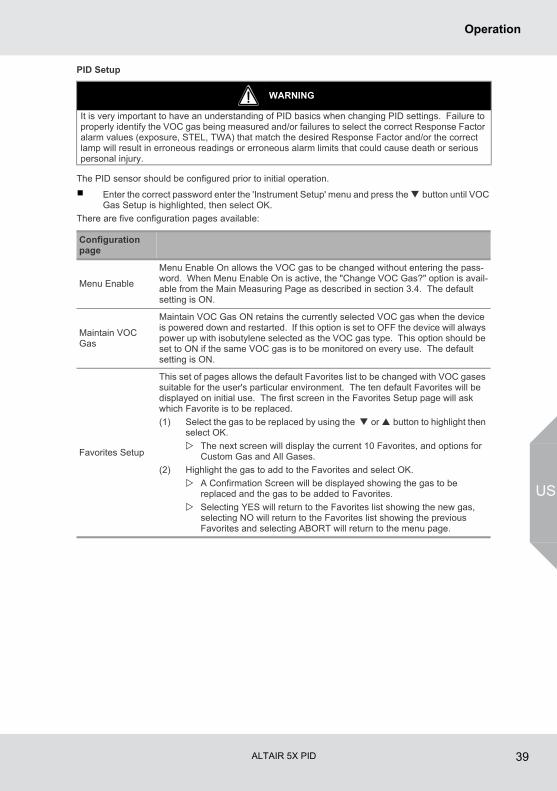
PID Setup
The PID sensor should be configured prior to initial operation.
Enter the correct password enter the 'Instrument Setup' menu and press the button until VOC Gas Setup is highlighted, then select OK.
There are five configuration pages available:
WARNING
It is very important to have an understanding of PID basics when changing PID settings. Failure to properly identify the VOC gas being measured and/or failures to select the correct Response Factor alarm values (exposure, STEL, TWA) that match the desired Response Factor and/or the correct lamp will result in erroneous readings or erroneous alarm limits that could cause death or serious personal injury.
Configuration page
Menu Enable
Menu Enable On allows the VOC gas to be changed without entering the pass-word. When Menu Enable On is active, the "Change VOC Gas?" option is avail-able from the Main Measuring Page as described in section 3.4. The default setting is ON.
Maintain VOC Gas
Maintain VOC Gas ON retains the currently selected VOC gas when the device is powered down and restarted. If this option is set to OFF the device will always power up with isobutylene selected as the VOC gas type. This option should be set to ON if the same VOC gas is to be monitored on every use. The default setting is ON.
Favorites Setup
This set of pages allows the default Favorites list to be changed with VOC gases suitable for the user's particular environment. The ten default Favorites will be displayed on initial use. The first screen in the Favorites Setup page will ask which Favorite is to be replaced.
(1) Select the gas to be replaced by using the or button to highlight then select OK.
The next screen will display the current 10 Favorites, and options for Custom Gas and All Gases.
(2) Highlight the gas to add to the Favorites and select OK.
A Confirmation Screen will be displayed showing the gas to be replaced and the gas to be added to Favorites.
Selecting YES will return to the Favorites list showing the new gas, selecting NO will return to the Favorites list showing the previous Favorites and selecting ABORT will return to the menu page.
ALTAIR 5X PID 40
Operation
US
Enabling BluetoothThe device is configured with a Bluetooth capable communications feature.
(1) Press the q button to enable or disable the Bluetooth communications device (ON/OFF).
(2) Press the button to to return to the Main Menu or the button to return to previous page.
Back To Main MenuThere are three options at this point:
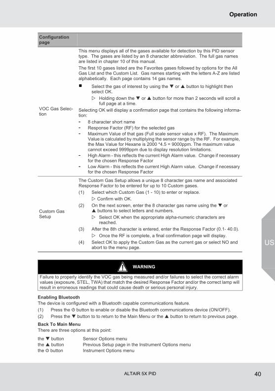
VOC Gas Selec-tion
This menu displays all of the gases available for detection by this PID sensor type. The gases are listed by an 8 character abbreviation. The full gas names are listed in chapter 10 of this manual.
The first 10 gases listed are the Favorites gases followed by options for the All Gas List and the Custom List. Gas names starting with the letters A-Z are listed alphabetically. Each page contains 14 gas names.
Select the gas of interest by using the or button to highlight then select OK.
Holding down the or button for more than 2 seconds will scroll a full page at a time.
Selecting OK will display a confirmation page that contains the following informa-tion:
- 8 character short name- Response Factor (RF) for the selected gas- Maximum Value of that gas (Full scale sensor value x RF). The Maximum
Value is calculated by multiplying the sensor range by the RF. For example, the Max Value for Hexane is 2000 *4.5 = 9000ppm. The maximum value cannot exceed 9999ppm due to display resolution limitations.
- High Alarm - this reflects the current High Alarm value. Change if necessary for the chosen Response Factor
- Low Alarm - this reflects the current High Alarm value. Change if necessary for the chosen Response Factor
Custom Gas Setup
The Custom Gas Setup allows a unique 8 character gas name and associated Response Factor to be entered for up to 10 Custom gases.
(1) Select which Custom Gas (1 - 10) to enter or replace.
Confirm with OK.
(2) On the next screen, enter the 8 character gas name using the or buttons to select letters and numbers.
Select OK when the appropriate alpha-numeric characters are reached.
(3) After the 8th character is entered, enter the Response Factor (0.1- 40.0).
Once the RF is complete, a final confirmation page will display.
(4) Select OK to apply the Custom Gas as the current gas or select NO and abort to the menu page.
Configuration page
WARNING
Failure to properly identify the VOC gas being measured and/or failures to select the correct alarm values (exposure, STEL, TWA) that match the desired Response Factor and/or the correct lamp will result in erroneous readings that could cause death or serious personal injury.
the button Sensor Options menuthe button Previous Setup page in the Instrument Options menuthe q button Instrument Options menu
ALTAIR 5X PID 41
Operation
US
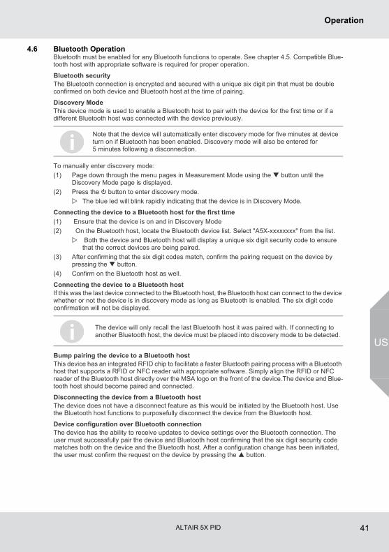
4.6 Bluetooth OperationBluetooth must be enabled for any Bluetooth functions to operate. See chapter 4.5. Compatible Blue-tooth host with appropriate software is required for proper operation.
Bluetooth securityThe Bluetooth connection is encrypted and secured with a unique six digit pin that must be double confirmed on both device and Bluetooth host at the time of pairing.
Discovery ModeThis device mode is used to enable a Bluetooth host to pair with the device for the first time or if a different Bluetooth host was connected with the device previously.
To manually enter discovery mode:
(1) Page down through the menu pages in Measurement Mode using the button until the Discovery Mode page is displayed.
(2) Press the q button to enter discovery mode.
The blue led will blink rapidly indicating that the device is in Discovery Mode.
Connecting the device to a Bluetooth host for the first time
(1) Ensure that the device is on and in Discovery Mode
(2) On the Bluetooth host, locate the Bluetooth device list. Select "A5X-xxxxxxxx" from the list.
Both the device and Bluetooth host will display a unique six digit security code to ensure that the correct devices are being paired.
(3) After confirming that the six digit codes match, confirm the pairing request on the device by pressing the button.
(4) Confirm on the Bluetooth host as well.
Connecting the device to a Bluetooth hostIf this was the last device connected to the Bluetooth host, the Bluetooth host can connect to the device whether or not the device is in discovery mode as long as Bluetooth is enabled. The six digit code confirmation will not be displayed.
Bump pairing the device to a Bluetooth hostThis device has an integrated RFID chip to facilitate a faster Bluetooth pairing process with a Bluetooth host that supports a RFID or NFC reader with appropriate software. Simply align the RFID or NFC reader of the Bluetooth host directly over the MSA logo on the front of the device.The device and Blue-tooth host should become paired and connected.
Disconnecting the device from a Bluetooth hostThe device does not have a disconnect feature as this would be initiated by the Bluetooth host. Use the Bluetooth host functions to purposefully disconnect the device from the Bluetooth host.
Device configuration over Bluetooth connectionThe device has the ability to receive updates to device settings over the Bluetooth connection. The user must successfully pair the device and Bluetooth host confirming that the six digit security code matches both on the device and the Bluetooth host. After a configuration change has been initiated, the user must confirm the request on the device by pressing the button.
Note that the device will automatically enter discovery mode for five minutes at device turn on if Bluetooth has been enabled. Discovery mode will also be entered for 5 minutes following a disconnection.
The device will only recall the last Bluetooth host it was paired with. If connecting to another Bluetooth host, the device must be placed into discovery mode to be detected.
ALTAIR 5X PID 42
Operation
US
Evacuation alert over Bluetooth connectionThe device has the ability to receive an evacuate message over the Bluetooth connection. The user must successfully pair the device and Bluetooth host confirming that the six digit security code matches both on the device and the Bluetooth host. Once connected, an evacuate message sent to the device will send the device into alarm while displaying EVACUATE on the display. Press the button to silence the Evacuation alert and confirm the alert was received. Press the button a second time to reset the Evacuation alert once in a safe area.
4.7 MSA Link OperationConnecting device to PC
(1) Switch ON the device and align the Datalink Communication port on the device to the IR inter-face of the PC.
(2) Start the MSA Link software on the PC and start the connection by clicking the connect icon.
4.8 Function Tests on the DeviceAlarm Test
Turn ON the device.
The user should verify that:- alarm LEDs flash- horn sounds briefly - vibrating alarm triggers briefly.
4.9 Bump Test
This test quickly confirms that the gas sensors are functioning. Perform a full calibration periodically to ensure accuracy and immediately if the device fails the Bump Test. The Bump Test can be performed using the procedure below or automatically using the GALAXY GX2 Test Stand.CSA requires (per 22.2 NO. 152) that combustible sensor sensitivity be tested before each day's use on a known concentration of methane equivalent to 25 to 50 % of full scale concentration. ACCURACY MUST BE WITHIN 0 to +20 % OF ACTUAL. Correct accuracy by performing the calibration procedure described in chapter 4.10.NOTE: The GALAXY GX2 cannot test the Chlorine Dioxide sensor. For this sensor, use this Bump Test procedure and/or manually calibrate as described in chapter 4.10.
EquipmentSee accessory chapter for ordering information for these components.- Calibration Check Gas Cylinder(s)
See chapter 6.3 for calibration gas target values and appropriate MSA calibration gas cylinders.
- Demand Flow Regulator(s)- Tubing appropriate for the gases to be tested- Kits containing tubing and regulators suitable for reactive and non-reactive gases are available
from MSA.
WARNING
Perform a Bump Test before each day’s use to verify proper device operation. Failure to perform this test can result in serious personal injury or death.
Bump test frequency is often stipulated by national or corporate regulations; however, bump testing before each day’s use is generally the accepted best safety practice and is therefore MSA’s recommendation.
ALTAIR 5X PID 43
Operation
US
Performing a Bump TestWhen bumping a PID sensor, use 100ppm isobutylene balanced in air.
(1) While the device is turned ON in a clean, fresh air environment, verify that readings indicate no gas is present.
(2) From the normal measure screen press the button to display “BUMP TEST?”.
(3) Verify the gas concentrations displayed match the Calibration Check Gas Cylinder. If they do not, adjust the values through the Calibration Setup menu.
Depending on the sensors installed, there could be one to five separate Bump Tests performed, each with a different cylinder, regulator, and tubing used.
(4) Attach the demand regulator (supplied in the calibration kit) to the cylinder providing the indi-cated gases.
(5) Connect tubing (supplied in the calibration kit) to the regulator.
(6) Attach the other end of tubing to the device pump inlet.
(7) Press the q button to start the bump test:
the progress bar advances
the sensors respond to the gas.
The message BUMP TEST PASS indicates a successful Bump Test of the sensors.If any sensor fails the Bump Test:- the message BUMP TEST FAIL appears- the failed sensor is indicated.If there are more sensors to be Bump Tested, the next sensor displays and the process repeats from Step 4.If there are no more sensors to be Bump Tested, the tubing can be removed from the device pump inlet.After the Bump TestAfter all installed sensors pass the Bump Test, the √ symbol displays on the MEASURE page. This √ symbol appears on the display in the upper feature barIf any sensor was not bump tested, or fails the Bump Test, the √ symbol does not display.The color display:- temporarily shows the √ symbol at each gas reading for successfully bump tested sensors- √ symbol is then replaced by the present gas reading.The √ symbol shows for 24 hours after the Bump Test.If a sensor fails the Bump Test, calibrate the device as described in chapter 4.10.
ALTAIR 5X PID 44
Operation
US
4.10 CalibrationThe ALTAIR 5X PID can be calibrated either manually using this procedure or automatically using the GALAXY GX2 test stand. Refer to chapter 11.5.The use of the demand regulators listed in chapter 9 is recommended. If a new sensor has been installed, the battery pack has been depleted or a new battery pack has been installed allow sensors to stabilize for 30 minutes before calibration is performed.
WARNING
Special conditions with toxic gases!If the device is to be checked or calibrated for reactive gases, prerequisites are required; otherwise, incorrect calibration would result in incorrect device operation.Reactive toxic gases (e.g., chlorine, ammonia, chlorine dioxide) have the property of diffusing into the rubber and plastic tubes so that the volume of test gas available in the device would no longer be sufficient to correctly perform device calibration.When calibrating the device with toxic gases, certain prerequisites are required, otherwise incorrect calibration could result:- A special pressure regulator- Shortest possible connection tubes between the pressure regulator and the device- Connection tubes made from a material that does not absorb the test gases (e.g., PTFE).NOTE: If using normal tubes and pressure regulators, expose them to the required test gas for an extended time period. Keep these materials dedicated for use with that test gas only; do not use them for other gases.For example, for chlorine, allow the entire contents of a test gas cylinder to flow through the pressure regulator and tubes before using to calibrate the device. Mark these materials for use with chlorine only.
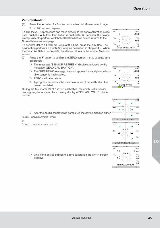
ALTAIR 5X PID 45
Operation
US
Zero Calibration(1) Press the button for five seconds in Normal Measurement page.
ZERO screen displays.
To skip the ZERO procedure and move directly to the span calibration proce-dure, push the button. If no button is pushed for 30 seconds, the device prompts user to perform a SPAN calibration before device returns to the Normal Measurement page.
To perform ONLY a Fresh Air Setup at this time, press the q button. The device then performs a Fresh Air Setup as described in chapter 4.2. When the Fresh Air Setup is complete, the device returns to the normal Measure screen.(2) Press the button to confirm the ZERO screen, i. e. to execute zero
calibration.
The message "SENSOR REFRESH" displays, followed by the message "ZERO CALIBRATION".
The "REFRESH" message does not appear if a catalytic combus-tible sensor is not installed.
ZERO calibration starts.
A progress bar shows the user how much of the calibration has been completed.
During the first moments of a ZERO calibration, the combustible sensor reading may be replaced by a moving display of “PLEASE WAIT”. This is normal.
After the ZERO calibration is completed the device displays either
“ZERO CALIBRATION PASS”
or
“ZERO CALIBRATION FAIL”.
Only if the device passes the zero calibration the SPAN screen displays.
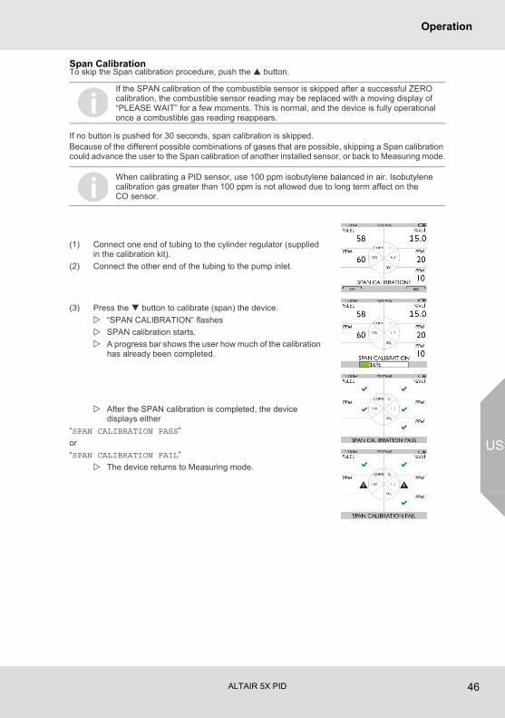
ALTAIR 5X PID 46
Operation
US
Span CalibrationTo skip the Span calibration procedure, push the button.
If no button is pushed for 30 seconds, span calibration is skipped.Because of the different possible combinations of gases that are possible, skipping a Span calibration could advance the user to the Span calibration of another installed sensor, or back to Measuring mode.
If the SPAN calibration of the combustible sensor is skipped after a successful ZERO calibration, the combustible sensor reading may be replaced with a moving display of “PLEASE WAIT” for a few moments. This is normal, and the device is fully operational once a combustible gas reading reappears.
When calibrating a PID sensor, use 100 ppm isobutylene balanced in air. Isobutylene calibration gas greater than 100 ppm is not allowed due to long term affect on the CO sensor.
(1) Connect one end of tubing to the cylinder regulator (supplied in the calibration kit).
(2) Connect the other end of the tubing to the pump inlet.
(3) Press the button to calibrate (span) the device.
“SPAN CALIBRATION“ flashes
SPAN calibration starts.
A progress bar shows the user how much of the calibration has already been completed.
After the SPAN calibration is completed, the device displays either
“SPAN CALIBRATION PASS”
or
“SPAN CALIBRATION FAIL”
The device returns to Measuring mode.
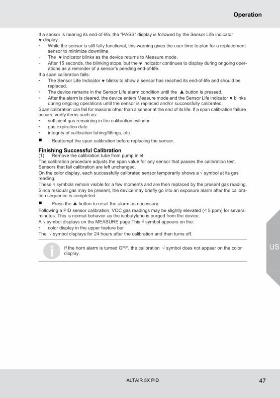
ALTAIR 5X PID 47
Operation
US
If a sensor is nearing its end-of-life, the "PASS" display is followed by the Sensor Life indicator ♥ display.- While the sensor is still fully functional, this warning gives the user time to plan for a replacement
sensor to minimize downtime.- The ♥ indicator blinks as the device returns to Measure mode.- After 15 seconds, the blinking stops, but the ♥ indicator continues to display during ongoing oper-
ations as a reminder of a sensor’s pending end-of-life.If a span calibration fails:- The Sensor Life Indicator ♥ blinks to show a sensor has reached its end-of-life and should be
replaced.- The device remains in the Sensor Life alarm condition until the button is pressed.- After the alarm is cleared, the device enters Measure mode and the Sensor Life indicator ♥ blinks
during ongoing operations until the sensor is replaced and/or successfully calibrated.Span calibration can fail for reasons other than a sensor at the end of its life. If a span calibration failure occurs, verify items such as:- sufficient gas remaining in the calibration cylinder- gas expiration date- integrity of calibration tubing/fittings, etc.
Reattempt the span calibration before replacing the sensor.
Finishing Successful Calibration(1) Remove the calibration tube from pump inlet.The calibration procedure adjusts the span value for any sensor that passes the calibration test. Sensors that fail calibration are left unchanged. On the color display, each successfully calibrated sensor temporarily shows a √ symbol at its gas reading. These √ symbols remain visible for a few moments and are then replaced by the present gas reading.Since residual gas may be present, the device may briefly go into an exposure alarm after the calibra-tion sequence is completed.
Press the button to reset the alarm as necessary.
Following a PID sensor calibration, VOC gas readings may be slightly elevated (< 5 ppm) for several minutes. This is normal behavior as the isobutylene is purged from the device.A √ symbol displays on the MEASURE page.This √ symbol appears on the:- color display in the upper feature barThe √ symbol displays for 24 hours after the calibration and then turns off.
If the horn alarm is turned OFF, the calibration √ symbol does not appear on the color display.
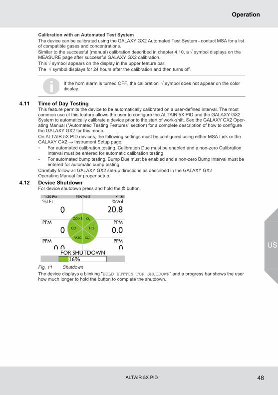
ALTAIR 5X PID 48
Operation
US
Calibration with an Automated Test SystemThe device can be calibrated using the GALAXY GX2 Automated Test System - contact MSA for a list of compatible gases and concentrations.Similar to the successful (manual) calibration described in chapter 4.10, a √ symbol displays on the MEASURE page after successful GALAXY GX2 calibration.This √ symbol appears on the display in the upper feature bar.The √ symbol displays for 24 hours after the calibration and then turns off.
4.11 Time of Day TestingThis feature permits the device to be automatically calibrated on a user-defined interval. The most common use of this feature allows the user to configure the ALTAIR 5X PID and the GALAXY GX2 System to automatically calibrate a device prior to the start of work-shift. See the GALAXY GX2 Oper-ating Manual ("Automated Testing Features" section) for a complete description of how to configure the GALAXY GX2 for this mode.On ALTAIR 5X PID devices, the following settings must be configured using either MSA Link or the GALAXY GX2 → Instrument Setup page:- For automated calibration testing, Calibration Due must be enabled and a non-zero Calibration
Interval must be entered for automatic calibration testing- For automated bump testing, Bump Due must be enabled and a non-zero Bump Interval must be
entered for automatic bump testingCarefully follow all GALAXY GX2 set-up directions as described in the GALAXY GX2 Operating Manual for proper setup.
4.12 Device ShutdownFor device shutdown press and hold the q button.
Fig. 11 Shutdown
The device displays a blinking "HOLD BUTTON FOR SHUTDOWN" and a progress bar shows the user how much longer to hold the button to complete the shutdown.
If the horn alarm is turned OFF, the calibration √ symbol does not appear on the color display.
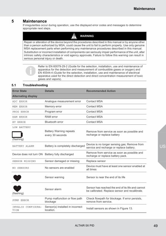
ALTAIR 5X PID 49
Maintenance
US
5 MaintenanceIf irregularities occur during operation, use the displayed error codes and messages to determine appropriate next steps.
5.1 Troubleshooting
WARNING
Repair or alteration of the device beyond the procedures described in this manual or by anyone other than a person authorized by MSA, could cause the unit to fail to perform properly. Use only genuine MSA replacement parts when performing any maintenance procedures described in this manual. Substitution or incorrect installation of components can seriously impair performance of the unit, alter intrinsic safety characteristics or void agency approvals. Failure to follow this warning can result in serious personal injury or death.
Refer to EN 60079-29-2 (Guide for the selection, installation, use and maintenance of apparatus for the detection and measurement of combustible gases or oxygen) and EN 45544-4 (Guide for the selection, installation, use and maintenance of electrical apparatus used for the direct detection and direct concentration measurement of toxic gases and vapors).
Error State Details Recommended Action
Alternating display
ADC ERROR Analogue measurement error Contact MSA
MEM ERROR Memory error Contact MSA
PROG ERROR Program error Contact MSA
RAM ERROR RAM error Contact MSA
BT ERROR Bluetooth error Contact MSA
LOW BATTERY
(flashing)
Battery Warning repeats
every 30 secondsRemove from service as soon as possible and recharge or replace battery
BATTERY ALARM Battery is completely dischargedDevice is no longer sensing gas; Remove from service and recharge or replace battery.
Device does not turn ON Battery fully dischargedRemove from service as soon as possible and recharge or replace battery pack.
SENSOR MISSING Sensor damaged or missing Replace sensor
NO SENSORS No sensors are enabledDevice must have at least one sensor enabled at all times
Sensor warning Sensor is near the end of its life
(flashing)
Sensor alarmSensor has reached the end of its life and cannot be calibrated. Replace sensor and recalibrate.
PUMP ERROR Pump malfunction or flow path blockage
Check flowpath for blockage. If error persists, remove from service.
INVALID CONFIGURA-TION
Sensor(s) installed in incorrect location.
Install sensors as shown in Figure 13.
ALTAIR 5X PID 50
Maintenance
US
5.2 Verifying Pump OperationUsers can check operation of the sampling system any time during operation by blocking the sampling system to generate a pump alarm.When the pump inlet, sample line or probe is blocked, the pump alarm must activate.Once gas readings are displayed, plug the free end of the sampling line or probe.- The pump motor shuts down and an alarm sounds.- PUMP ERROR will flash on the display.
Press the button to reset the alarm and restart the pump.
If the alarm does not activate:- Check the sample line and probe for leaks.- Once leak is fixed, recheck pump alarm by blocking the flow.
Press the button to reset the alarm and restart the pump.
During operation, a pump alarm may occur when the:- Flow system is blocked- Pump is inoperative- Sample lines are attached or removed.
To Clear Pump Alarm
(1) Correct any flow blockage.
(2) Press the button.
The Pump will now restart.
WARNING
Do not use the device, sample line, or probe unless the pump alarm activates when the flow is blocked. Lack of an alarm is an indication that a sample may not be drawn to the sensors, which could cause inaccurate readings. If a sample line or probe is installed and the pump alarm does not activate, remove the line or probe and repeat the test. This will provide information on where the blockage is located.Failure to follow the above can result in serious personal injury or death.Never let the end of the sampling line touch or go under any liquid surface. If liquid is drawn into the device, readings will be inaccurate and device could be damaged. We recommend the use of an MSA sample probe containing a special membrane filter, permeable to gas but impermeable to water, to prevent such an occurrence.
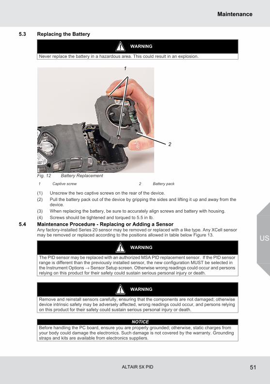
ALTAIR 5X PID 51
Maintenance
US
5.3 Replacing the Battery
Fig. 12 Battery Replacement
(1) Unscrew the two captive screws on the rear of the device.
(2) Pull the battery pack out of the device by gripping the sides and lifting it up and away from the device.
(3) When replacing the battery, be sure to accurately align screws and battery with housing.
(4) Screws should be tightened and torqued to 5.5 in lb.
5.4 Maintenance Procedure - Replacing or Adding a SensorAny factory-installed Series 20 sensor may be removed or replaced with a like type. Any XCell sensor may be removed or replaced according to the positions allowed in table below Figure 13.
WARNING
Never replace the battery in a hazardous area. This could result in an explosion.
1 Captive screw 2 Battery pack
1
2
WARNING
The PID sensor may be replaced with an authorized MSA PID replacement sensor. If the PID sensor range is different than the previously installed sensor, the new configuration MUST be selected in the Instrument Options → Sensor Setup screen. Otherwise wrong readings could occur and persons relying on this product for their safety could sustain serious personal injury or death.
WARNING
Remove and reinstall sensors carefully, ensuring that the components are not damaged; otherwise device intrinsic safety may be adversely affected, wrong readings could occur, and persons relying on this product for their safety could sustain serious personal injury or death.
NOTICEBefore handling the PC board, ensure you are properly grounded; otherwise, static charges from your body could damage the electronics. Such damage is not covered by the warranty. Grounding straps and kits are available from electronics suppliers.
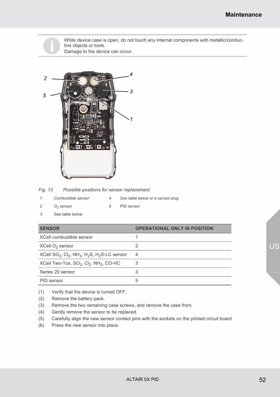
ALTAIR 5X PID 52
Maintenance
US
Fig. 13 Possible positions for sensor replacement
(1) Verify that the device is turned OFF.
(2) Remove the battery pack.
(3) Remove the two remaining case screws, and remove the case front.
(4) Gently remove the sensor to be replaced.
(5) Carefully align the new sensor contact pins with the sockets on the printed circuit board.
(6) Press the new sensor into place.
While device case is open, do not touch any internal components with metallic/conduc-tive objects or tools.Damage to the device can occur.
1 Combustible sensor 4 See table below or a sensor plug
2 O2 sensor 5 PID sensor
3 See table below
SENSOR OPERATIONAL ONLY IN POSITION
XCell combustible sensor 1
XCell O2 sensor 2
XCell SO2, Cl2, NH3, H2S, H2S-LC sensor 4
XCell Two-Tox, SO2, Cl2, NH3, CO-HC 3
Series 20 sensor 3
PID sensor 5
2
1
3
4
5
ALTAIR 5X PID 53
Maintenance
US
(7) Note the position restrictions in the table above.
Adapter (part no. 10110183) is required for XCell usage in position 3.
If a sensor is removed and will not be replaced, be sure to install a sensor plug in its place in order to maintain correct device function.
The plug for XCell positions is P/N 10105650.
The Series 20 plug is P/N 10088192.
(8) Visually inspect the green gasket, assuring that it is seated properly in the front housing.
(9) Attach front case and tighten two case screws using 5.5 in-lbs of torque.
(10) Attach the battery pack and tighten the two battery pack screws using 5.5 in-lbs of torque.If a change in XCell Sensor configuration is detected during the device turn-ON process:- The "ACCEPT?" prompt appears on the display- The button accepts the sensor configuration- The button rejects the sensor configuration; the device is not operational.When an XCell sensor is replaced, the device automatically enables the sensor after the change has been accepted. If a Series 20 or PID sensor is replaced, it must be manually enabled (→ chapter 4.5, SETTING SENSOR OPTIONS).If the oxygen sensor was replaced, see chapter 4.2 regarding the oxygen reading display.
(11) Allow sensors to stabilize at least 30 minutes before calibration.
(12) Calibrate device before use.
WARNING
Calibration is required after a sensor is installed; otherwise, the device will not perform as expected and persons relying on this product for their safety could sustain serious personal injury or death.
ALTAIR 5X PID 54
Maintenance
US
5.5 Replacing the Pump Filter(1) Turn OFF the device.
(2) Unscrew the two captive screws from the clear filter cover on the back of the device to access the filter.
(3) Carefully lift out the O-ring and the filter disk(s).
(4) Use both the paper-like filter and the fibrous dust filter (the thicker disk) as supplied in the Main-tenance Kit if the device is NOT configured to use a reactive toxic gas sensor (does not have a Cl2, ClO2, or NH3 sensor).
Use ONLY the paper filter supplied in the Reactive Gas Maintenance Kit if the device IS config-ured to use a reactive toxic gas sensor (Cl2, ClO2, or NH3).
(5) Place the new paper-like filter into the recess in the back of the device. If it is to be used, place the fibrous dust filter into the clear filter cover.
(6) Replace the O-ring in the recess.
(7) Re-install the clear filter cover on the back of the device.
5.6 Cleaning the Device ExteriorClean the exterior of the device regularly using only a damp cloth. Do not use cleaning agents as many contain silicones which will damage the combustible sensor.
5.7 StorageWhen not in use, store the device in a safe, dry place between 18 °C (65 °F) and 30 °C (86 °F). After storage, always recheck device calibration before use. If not to be used in 30 days, remove battery pack or connect it to a charger.
5.8 ShipmentPack the device in its original shipping container with suitable padding. If the original container is unavailable, an equivalent container may be substituted.
5.9 PID Sensor Cleaning and Maintenance Procedure
WARNING
Use of the fibrous dust filter or the incorrect paper filter for the measurement of reactive gases could cause erroneous readings.
WARNING
All maintenance procedures must be performed on a clean surface using clean tools. Avoid touching the lamp's window as well as the metalized portion of the Cell Assembly with bare fingers. Finger-prints left on these parts may adversely affect the sensors operation. Latex gloves are recom-mended, but if they are not used, hands must be clean and free of oils, lotions, etc. It is acceptable to hold the lamp by its glass body or by the edges of the window.Remove and reinstall sensors carefully, ensuring that the components are not damaged; otherwise device intrinsic safety may be adversely affected, wrong readings could occur, and persons relying on this product for their safety could sustain serious personal injury or death.
NOTICEWhile device case is open, do not touch any internal components with metallic/conductive objects or tools. Damage to the device can occur.
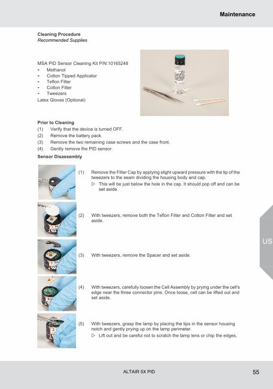
ALTAIR 5X PID 55
Maintenance
US
Cleaning ProcedureRecommended Supplies
Prior to Cleaning
(1) Verify that the device is turned OFF.
(2) Remove the battery pack.
(3) Remove the two remaining case screws and the case front.
(4) Gently remove the PID sensor.
Sensor Disassembly
MSA PID Sensor Cleaning Kit P/N:10165248
- Methanol- Cotton Tipped Applicator- Teflon Filter- Cotton Filter- Tweezers
Latex Gloves (Optional)
(1) Remove the Filter Cap by applying slight upward pressure with the tip of the tweezers to the seam dividing the housing body and cap.
This will be just below the hole in the cap. It should pop off and can be set aside.
(2) With tweezers, remove both the Teflon Filter and Cotton Filter and set aside.
(3) With tweezers, remove the Spacer and set aside.
(4) With tweezers, carefully loosen the Cell Assembly by prying under the cell's edge near the three connector pins. Once loose, cell can be lifted out and set aside.
(5) With tweezers, grasp the lamp by placing the tips in the sensor housing notch and gently prying up on the lamp perimeter.
Lift out and be careful not to scratch the lamp lens or chip the edges.
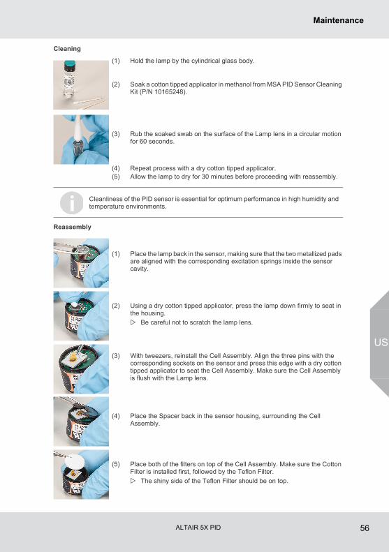
ALTAIR 5X PID 56
Maintenance
US
Cleaning
Reassembly
(1) Hold the lamp by the cylindrical glass body.
(2) Soak a cotton tipped applicator in methanol from MSA PID Sensor Cleaning Kit (P/N 10165248).
(3) Rub the soaked swab on the surface of the Lamp lens in a circular motion for 60 seconds.
(4) Repeat process with a dry cotton tipped applicator.(5) Allow the lamp to dry for 30 minutes before proceeding with reassembly.
Cleanliness of the PID sensor is essential for optimum performance in high humidity and temperature environments.
(1) Place the lamp back in the sensor, making sure that the two metallized pads are aligned with the corresponding excitation springs inside the sensor cavity.
(2) Using a dry cotton tipped applicator, press the lamp down firmly to seat in the housing.
Be careful not to scratch the lamp lens.
(3) With tweezers, reinstall the Cell Assembly. Align the three pins with the corresponding sockets on the sensor and press this edge with a dry cotton tipped applicator to seat the Cell Assembly. Make sure the Cell Assembly is flush with the Lamp lens.
(4) Place the Spacer back in the sensor housing, surrounding the Cell Assembly.
(5) Place both of the filters on top of the Cell Assembly. Make sure the Cotton Filter is installed first, followed by the Teflon Filter.
The shiny side of the Teflon Filter should be on top.
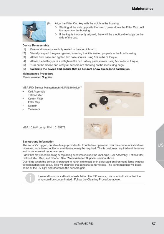
ALTAIR 5X PID 57
Maintenance
US
Device Re-assembly
(1) Ensure all sensors are fully seated in the circuit board.
(2) Visually inspect the green gasket, assuring that it is seated properly in the front housing.
(3) Attach front case and tighten two case screws using 5.5 in-lbs of torque.
(4) Attach the battery pack and tighten the two battery pack screws using 5.5 in-lbs of torque.
(5) Turn on the device and verify all sensors are showing on the measuring page.
(6) Calibrate the device and ensure that all sensors show successful calibration.
Maintenance ProcedureRecommended Supplies
Background InformationThe sensor's rugged, durable design provides for trouble-free operation over the course of its lifetime. However, in certain conditions, maintenance may be required. This is customer required maintenance and is not covered under warranty.Parts that may need cleaning or replacing over time include the UV Lamp, Cell Assembly, Teflon Filter, Cotton Filter, Cap, and Spacer. See Recommended Supplies section above.Over time when the sensor is exposed to harsh chemicals or in a polluted environment, lamp window contamination can occur. This will degrade the sensor's performance. The contamination will block some of the UV light and decrease the sensors gain.
(6) Align the Filter Cap key with the notch in the housing:
Starting at the side opposite the notch, press down the Filter Cap until it snaps onto the housing.
If the key is incorrectly aligned, there will be a noticeable bulge on the side of the cap.
MSA PID Sensor Maintenance Kit P/N:10165247
- Cell Assembly- Teflon Filter- Cotton Filter- Filter Cap- Spacer- Tweezers
MSA 10.6eV Lamp P/N: 10165272
If several bump or calibration tests fail on the PID sensor, this is an indication that the lamp could be contaminated. Follow the Cleaning Procedure above.
ALTAIR 5X PID 58
Maintenance
US
PID Error States
When PID LAMP ERROR is displayed, it is required to carry out the following sensor maintenance procedure.
(1) Thoroughly review the PID sensor assembly and verify all components are present and installed correctly.
(2) If assembly is correct then follow the lamp cleaning procedure.
For lamp cleaning instructions, refer to Cleaning Procedure section above.
(3) If the lamp is cleaned and a PID error still exists, replace the lamp.
(4) If the lamp is replaced and a PID error still exists, replace the cell assembly.If error still exists, device should be sent to an authorized MSA repair center.
PID Error States Details Recommended Action
Device Display
PID LAMP ERROR
This error indicates that there is an error with the UV lamp in the PID sensor. Possible causes include:
- lamp not installed - lamp not installed
correctly - damaged lamp - non-functioning lamp.
This test is functional at temperatures ≤ 30 °C
Complete a calibration. If the device fails cali-bration, the device should be shut down and cleaning procedure should be followed paying careful attention to the orientation of the lamp.
If user is not in a location where the mainte-nance procedure can be followed, the PID sensor can be disabled through the security menu. This will allow other functioning sensors to continue working with the PID disabled.
NOTE: The error may occur when installing a new PID sensor into the device. This is expected and the error will be cleared when the device is calibrated.
PID SENSOR ERRORThis is a fatal and non-recov-erable error indicating a failure in the sensor.
Device should be shut down and sent to an authorized MSA repair center.
Calibration
Fail
At the completion of the cali-bration sequence a Fail message is displayed. On Galaxy GX2, user can press the Calibration Details button to determine which sensor failed.
If PID sensor failed calibration, device should be reviewed and then calibration should be re-run. If PID calibration fails a second time, device should be shut down and the cleaning procedure should be followed.
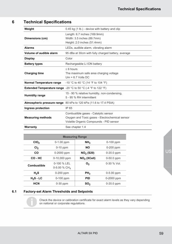
ALTAIR 5X PID 59
Technical Specifications
US
6 Technical Specifications
6.1 Factory-set Alarm Thresholds and Setpoints
Weight 0.45 kg (1 lb.) - device with battery and clip
Dimensions (cm)
Length: 6.7 inches (169.9mm)
Width: 3.5 inches (89.7mm)
Height: 2.0 inches (51.4mm)
Alarms LEDs, audible alarm, vibrating alarm
Volume of audible alarm 95 dBa at 30cm with fully charged battery, average
Display Color
Battery types Rechargeable Li ION battery
Charging time
≤ 6 hours
The maximum safe area charging voltage
Um = 6.7 Volts DC
Normal Temperature range -10 °C to 40 °C (14 °F to 104 °F)
Extended Temperature range -20 °C to 50 °C (-4 °F to 122 °F)
Humidity range15 - 90 % relative humidity, non-condensing,
5 - 95 % RH intermittent
Atmospheric pressure range 80 kPa to 120 kPa (11.6 to 17.4 PSIA)
Ingress protection IP 65
Measuring methods
Combustible gases - Catalytic sensor
Oxygen and Toxic gases - Electrochemical sensor
Volatile Organic Compounds - PID sensor
Warranty See chapter 1.4
Measuring Range
CIO2 0-1.00 ppm NH3 0-100 ppm
Cl2 0-10 ppm NO 0-200 ppm
CO 0-2000 ppm NO2 (S20) 0-20.0 ppm
CO - HC 0-10,000 ppm NO2 (XCell) 0-50.0 ppm
Combustible0-100 % LEL
0-5.00 % CH4
O2 0-30 % Vol.
H2S 0-200 ppm PH3 0-5.00 ppm
H2S - LC 0-100 ppm PID 0-2000 ppm
HCN 0-30 ppm SO2 0-20.0 ppm
Check the device or calibration certificate for exact alarm levels as they vary depending on national or corporate regulations.
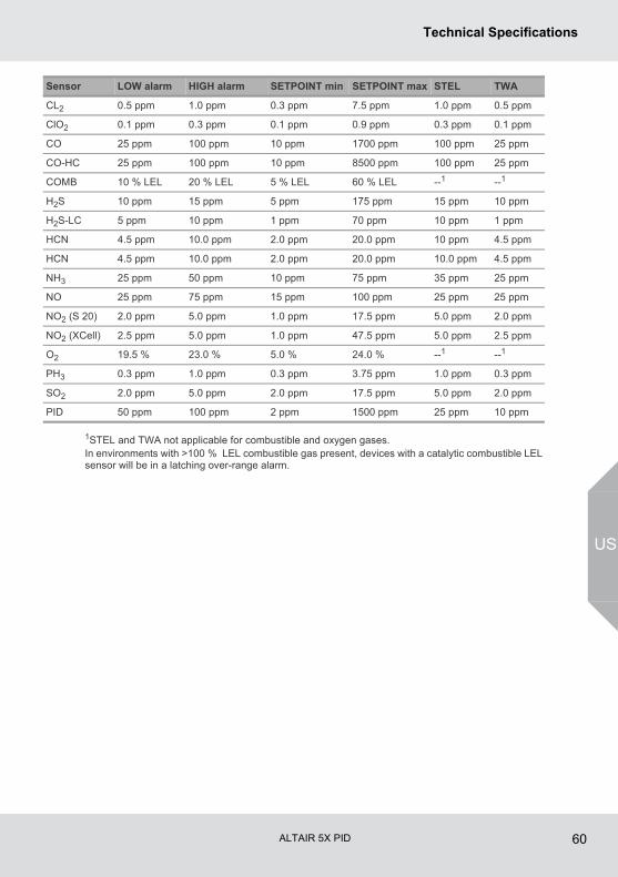
ALTAIR 5X PID 60
Technical Specifications
US
1STEL and TWA not applicable for combustible and oxygen gases.In environments with >100 % LEL combustible gas present, devices with a catalytic combustible LEL sensor will be in a latching over-range alarm.
Sensor LOW alarm HIGH alarm SETPOINT min SETPOINT max STEL TWA
CL2 0.5 ppm 1.0 ppm 0.3 ppm 7.5 ppm 1.0 ppm 0.5 ppm
ClO2 0.1 ppm 0.3 ppm 0.1 ppm 0.9 ppm 0.3 ppm 0.1 ppm
CO 25 ppm 100 ppm 10 ppm 1700 ppm 100 ppm 25 ppm
CO-HC 25 ppm 100 ppm 10 ppm 8500 ppm 100 ppm 25 ppm
COMB 10 % LEL 20 % LEL 5 % LEL 60 % LEL --1 --1
H2S 10 ppm 15 ppm 5 ppm 175 ppm 15 ppm 10 ppm
H2S-LC 5 ppm 10 ppm 1 ppm 70 ppm 10 ppm 1 ppm
HCN 4.5 ppm 10.0 ppm 2.0 ppm 20.0 ppm 10 ppm 4.5 ppm
HCN 4.5 ppm 10.0 ppm 2.0 ppm 20.0 ppm 10.0 ppm 4.5 ppm
NH3 25 ppm 50 ppm 10 ppm 75 ppm 35 ppm 25 ppm
NO 25 ppm 75 ppm 15 ppm 100 ppm 25 ppm 25 ppm
NO2 (S 20) 2.0 ppm 5.0 ppm 1.0 ppm 17.5 ppm 5.0 ppm 2.0 ppm
NO2 (XCell) 2.5 ppm 5.0 ppm 1.0 ppm 47.5 ppm 5.0 ppm 2.5 ppm
O2 19.5 % 23.0 % 5.0 % 24.0 % --1 --1
PH3 0.3 ppm 1.0 ppm 0.3 ppm 3.75 ppm 1.0 ppm 0.3 ppm
SO2 2.0 ppm 5.0 ppm 2.0 ppm 17.5 ppm 5.0 ppm 2.0 ppm
PID 50 ppm 100 ppm 2 ppm 1500 ppm 25 ppm 10 ppm
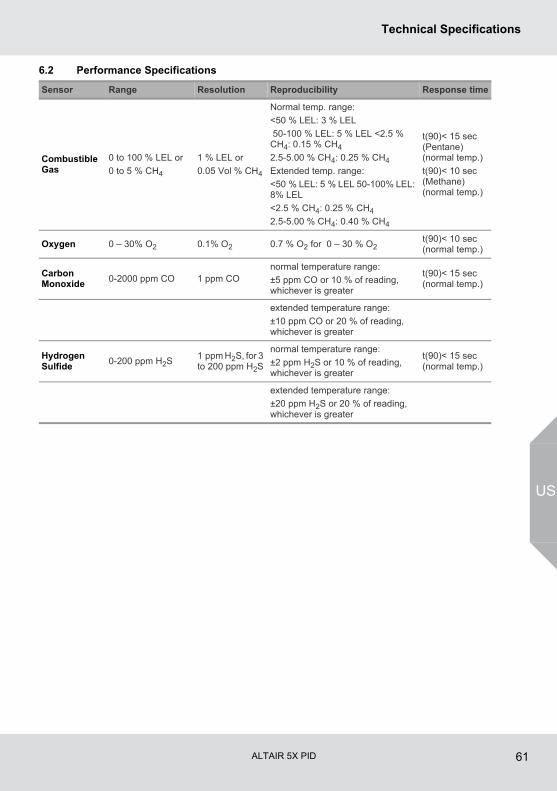
ALTAIR 5X PID 61
Technical Specifications
US
6.2 Performance Specifications
Sensor Range Resolution Reproducibility Response time
Combustible Gas
0 to 100 % LEL or
0 to 5 % CH4
1 % LEL or
0.05 Vol % CH4
Normal temp. range:
<50 % LEL: 3 % LEL
50-100 % LEL: 5 % LEL <2.5 % CH4: 0.15 % CH4
2.5-5.00 % CH4: 0.25 % CH4
Extended temp. range:
<50 % LEL: 5 % LEL 50-100% LEL: 8% LEL
<2.5 % CH4: 0.25 % CH4
2.5-5.00 % CH4: 0.40 % CH4
t(90)< 15 sec (Pentane) (normal temp.)
t(90)< 10 sec (Methane) (normal temp.)
Oxygen 0 – 30% O2 0.1% O2 0.7 % O2 for 0 – 30 % O2t(90)< 10 sec (normal temp.)
Carbon Monoxide
0-2000 ppm CO 1 ppm COnormal temperature range:
±5 ppm CO or 10 % of reading, whichever is greater
t(90)< 15 sec (normal temp.)
extended temperature range:
±10 ppm CO or 20 % of reading, whichever is greater
Hydrogen Sulfide
0-200 ppm H2S1 ppm H2S, for 3 to 200 ppm H2S
normal temperature range:
±2 ppm H2S or 10 % of reading, whichever is greater
t(90)< 15 sec (normal temp.)
extended temperature range:
±20 ppm H2S or 20 % of reading, whichever is greater
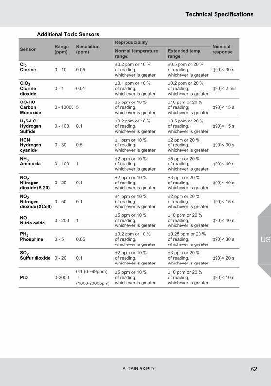
ALTAIR 5X PID 62
Technical Specifications
US
Additional Toxic Sensors
SensorRange (ppm)
Resolution (ppm)
ReproducibilityNominal responseNormal temperature
range:Extended temp. range:
Cl2Clorine 0 - 10 0.05
±0.2 ppm or 10 % of reading, whichever is greater
±0.5 ppm or 20 % of reading, whichever is greater
t(90)< 30 s
ClO2Clorine dioxide
0 - 1 0.01±0.1 ppm or 10 % of reading, whichever is greater
±0.2 ppm or 20 % of reading, whichever is greater
t(90)< 2 min
CO-HC Carbon Monoxide
0 - 10000 5±5 ppm or 10 % of reading, whichever is greater
±10 ppm or 20 % of reading, whichever is greater
t(90)< 15 s
H2S-LC Hydrogen Sulfide
0 - 100 0.1±0.2 ppm or 10 % of reading, whichever is greater
±0.5 ppm or 20 % of reading, whichever is greater
t(90)< 15 s
HCNHydrogen cyanide
0 - 30 0.5±1 ppm or 10 % of reading, whichever is greater
±2 ppm or 20 % of reading, whichever is greater
t(90)< 30 s
NH3Ammonia 0 - 100 1
±2 ppm or 10 % of reading, whichever is greater
±5 ppm or 20 % of reading, whichever is greater
t(90)< 40 s
NO2Nitrogen dioxide (S 20)
0 - 20 0.1±2 ppm or 10 % of reading, whichever is greater
±3 ppm or 20 % of reading, whichever is greater
t(90)< 40 s
NO2Nitrogen dioxide (XCell)
0 - 50 0.1±1 ppm or 10 % of reading, whichever is greater
±2 ppm or 20 % of reading, whichever is greater
t(90)< 15 s
NONitric oxide
0 - 200 1±5 ppm or 10 % of reading, whichever is greater
±10 ppm or 20 % of reading, whichever is greater
t(90)< 40 s
PH3Phosphine 0 - 5 0.05
±0.2 ppm or 10 % of reading, whichever is greater
±0.25 ppm or 20 % of reading, whichever is greater
t(90)< 30 s
SO2Sulfur dioxide 0 - 20 0.1
±2 ppm or 10 % of reading, whichever is greater
±3 ppm or 20 % of reading, whichever is greater
t(90)< 20 s
PID 0-20000.1 (0-999ppm)
1 (1000-2000ppm)
±5 ppm or 10 % of reading, whichever is greater
±10 ppm or 20 % of reading, whichever is greater
t(90)< 10 s
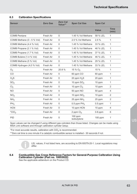
ALTAIR 5X PID 63
Technical Specifications
US
6.3 Calibration Specifications
6.4 Combustible Gas Cross Reference Factors for General-Purpose Calibration Using Calibration Cylinder (Part no. 10053022)See the applicable addendum on the Product CD.
Sensor Zero GasZero Cal Value**
Span Cal Gas Span Cal
ValueTime (min)
COMB Pentane Fresh Air 0 1.45 % Vol Methane 58 % LEL 1
COMB Methane (0 - 5 % Vol) Fresh Air 0 2.5 % Vol Methane 2,5 % 1
COMB Methane (4.4 % Vol) Fresh Air 0 1.45 % Vol Methane 33 % LEL 1
COMB Propane (2.1 % Vol) Fresh Air 0 1.45 % Vol Methane 46 % LEL 1
COMB Propane (1.7 % Vol) Fresh Air 0 1.45 % Vol Methane 37 % LEL 1
COMB Butane (1.4 % Vol) Fresh Air 0 1.45 % Vol Methane 46 % LEL 1
COMB Methane (5 % Vol) Fresh Air 0 1.45 % Vol Methane 29 % LEL 1
COMB Hydrogen (4,0 % Vol) Fresh Air 0 1.45 % Vol Methane 33 % LEL 1
O2 Fresh Air 20.8 % 15 % O2 15 % 1
CO Fresh Air 0 60 ppm CO 60 ppm 1
H2S Fresh Air 0 20 ppm H2S 20 ppm 1
SO2 Fresh Air 0 10 ppm SO2 10 ppm 1
Cl2 Fresh Air 0 10 ppm Cl2 10 ppm 2
NO Fresh Air 0 50 ppm NO 50 ppm 4
NO2 Fresh Air 0 10 ppm NO2 10 ppm 2
NH3 Fresh Air 0 25 ppm NH3 25 ppm 2
PH3 Fresh Air 0 0.5 ppm PH3 0.5 ppm 1
HCN Fresh Air 0 10 ppm HCN 10 ppm 4
*ClO2 Fresh Air 0 2 ppm Cl2 0.8 ppm 6
PID Fresh Air 0100 ppm isobutylene
100 ppm 1
Span values can be changed if using different gas cylinders than those listed. Changes can be made using MSA Link software and through calibration cylinder setup.
*For most accurate results, calibration with ClO2 is recommended.
**Zero cal time is one minute if a catalytic combustible sensor is installed - 30 seconds if not.
LEL values, if not listed here, are according to EN 60079-20-1. Local regulations may differ.
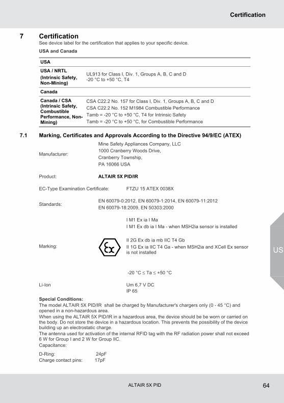
ALTAIR 5X PID 64
Certification
US
7 CertificationSee device label for the certification that applies to your specific device.
USA and Canada
7.1 Marking, Certificates and Approvals According to the Directive 94/9/EC (ATEX)
Special Conditions:The model ALTAIR 5X PID/IR shall be charged by Manufacturer's chargers only (0 - 45 °C) and opened in a non-hazardous area.When using the ALTAIR 5X PID/IR in a hazardous area, the device should be be worn or carried on the body. Do not store the device in a hazardous location. This prevents the possibility of the device building up an electrostatic charge.The antenna used for activation of the internal RFID tag with the RF radiation power shall not exceed 6 W for Group I and 2 W for Group IIC. Capacitance:
USA
USA / NRTL
(Intrinsic Safety, Non-Mining)
UL913 for Class I, Div. 1, Groups A, B, C and D-20 °C to +50 °C, T4
Canada
Canada / CSA (Intrinsic Safety, Combustible Performance, Non-Mining)
CSA C22.2 No. 157 for Class I, Div. 1, Groups A, B, C and D
CSA C22.2 No. 152 M1984 Combustible Performance
Tamb = -20 °C to +50 °C, T4 for Intrinsic Safety
Tamb = -20 °C to +50 °C, for Combustible Performance
Manufacturer:
Mine Safety Appliances Company, LLC
1000 Cranberry Woods Drive,
Cranberry Township,
PA 16066 USA
Product: ALTAIR 5X PID/IR
EC-Type Examination Certificate: FTZU 15 ATEX 0038X
Standards:EN 60079-0:2012, EN 60079-1:2014, EN 60079-11:2012
EN 60079-18:2009, EN 50303:2000
Marking:
I M1 Ex ia I Ma
I M1 Ex db ia I Ma - when MSH2ia sensor is installed
II 2G Ex db ia mb IIC T4 Gb
II 1G Ex ia IIC T4 Ga - when MSH2ia and XCell Ex sensor is not installed
-20 °C ≤ Ta ≤ +50 °C
Li-Ion Um 6,7 V DCIP 65
D-Ring: 24pFCharge contact pins: 17pF
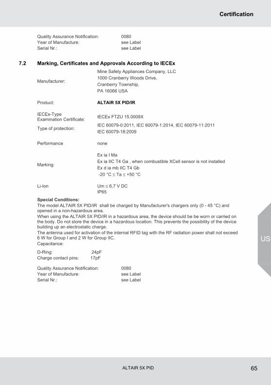
ALTAIR 5X PID 65
Certification
US
7.2 Marking, Certificates and Approvals According to IECEx
Special Conditions:The model ALTAIR 5X PID/IR shall be charged by Manufacturer's chargers only (0 - 45 °C) and opened in a non-hazardous area.When using the ALTAIR 5X PID/IR in a hazardous area, the device should be be worn or carried on the body. Do not store the device in a hazardous location. This prevents the possibility of the device building up an electrostatic charge.The antenna used for activation of the internal RFID tag with the RF radiation power shall not exceed 6 W for Group I and 2 W for Group IIC. Capacitance:
Quality Assurance Notification: 0080Year of Manufacture: see LabelSerial Nr.: see Label
Manufacturer:
Mine Safety Appliances Company, LLC
1000 Cranberry Woods Drive,
Cranberry Township,
PA 16066 USA
Product: ALTAIR 5X PID/IR
IECEx-Type Examination Certificate:
IECEx FTZU 15.0009X
Type of protection:IEC 60079-0:2011, IEC 60079-1:2014, IEC 60079-11:2011
IEC 60079-18:2009
Performance none
Marking:
Ex ia I Ma
Ex ia IIC T4 Ga , when combustible XCell sensor is not installed
Ex d ia mb IIC T4 Gb
-20 °C ≤ Ta ≤ +50 °C
Li-Ion Um ≤ 6,7 V DCIP65
D-Ring: 24pFCharge contact pins: 17pF
Quality Assurance Notification: 0080Year of Manufacture: see LabelSerial Nr.: see Label
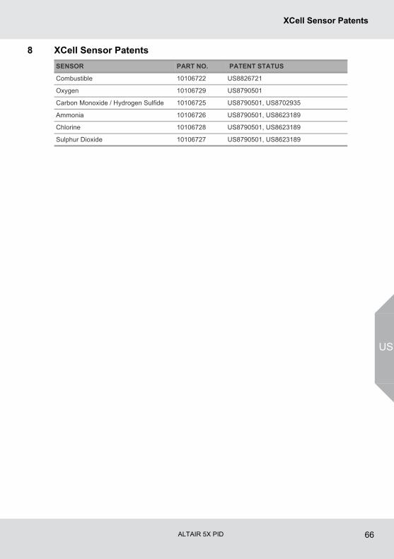
ALTAIR 5X PID 66
XCell Sensor Patents
US
8 XCell Sensor Patents
SENSOR PART NO. PATENT STATUS
Combustible 10106722 US8826721
Oxygen 10106729 US8790501
Carbon Monoxide / Hydrogen Sulfide 10106725 US8790501, US8702935
Ammonia 10106726 US8790501, US8623189
Chlorine 10106728 US8790501, US8623189
Sulphur Dioxide 10106727 US8790501, US8623189
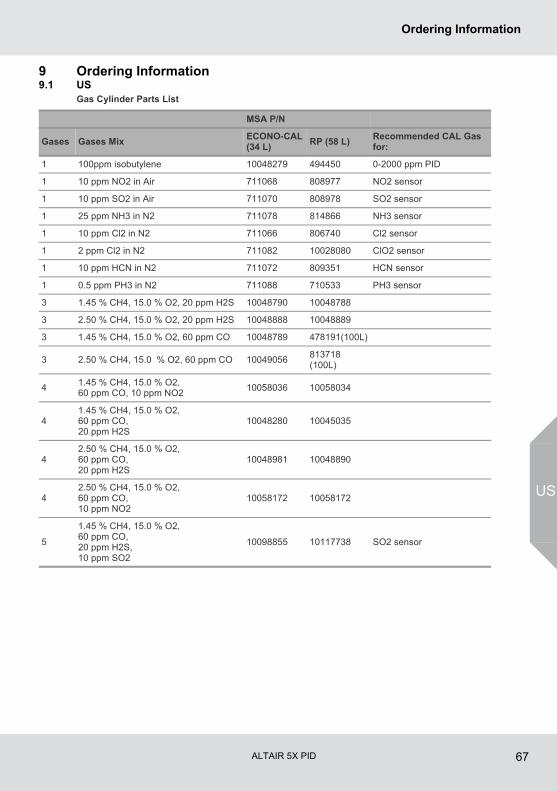
ALTAIR 5X PID 67
Ordering Information
US
9 Ordering Information9.1 US
Gas Cylinder Parts List
MSA P/N
Gases Gases MixECONO-CAL (34 L)
RP (58 L)Recommended CAL Gas for:
1 100ppm isobutylene 10048279 494450 0-2000 ppm PID
1 10 ppm NO2 in Air 711068 808977 NO2 sensor
1 10 ppm SO2 in Air 711070 808978 SO2 sensor
1 25 ppm NH3 in N2 711078 814866 NH3 sensor
1 10 ppm Cl2 in N2 711066 806740 Cl2 sensor
1 2 ppm Cl2 in N2 711082 10028080 ClO2 sensor
1 10 ppm HCN in N2 711072 809351 HCN sensor
1 0.5 ppm PH3 in N2 711088 710533 PH3 sensor
3 1.45 % CH4, 15.0 % O2, 20 ppm H2S 10048790 10048788
3 2.50 % CH4, 15.0 % O2, 20 ppm H2S 10048888 10048889
3 1.45 % CH4, 15.0 % O2, 60 ppm CO 10048789 478191(100L)
3 2.50 % CH4, 15.0 % O2, 60 ppm CO 10049056813718 (100L)
41.45 % CH4, 15.0 % O2, 60 ppm CO, 10 ppm NO2
10058036 10058034
41.45 % CH4, 15.0 % O2, 60 ppm CO, 20 ppm H2S
10048280 10045035
42.50 % CH4, 15.0 % O2, 60 ppm CO, 20 ppm H2S
10048981 10048890
42.50 % CH4, 15.0 % O2, 60 ppm CO, 10 ppm NO2
10058172 10058172
5
1.45 % CH4, 15.0 % O2, 60 ppm CO, 20 ppm H2S, 10 ppm SO2
10098855 10117738 SO2 sensor
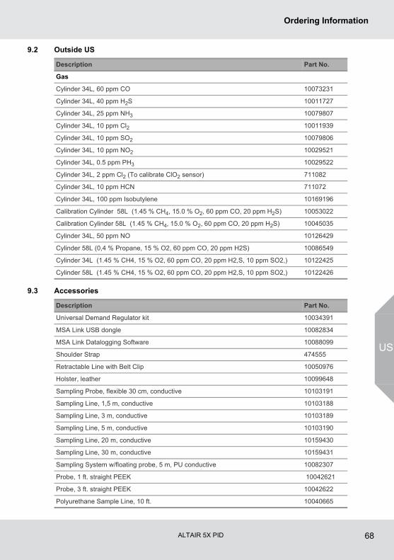
ALTAIR 5X PID 68
Ordering Information
US
9.2 Outside US
9.3 Accessories
Description Part No.
Gas
Cylinder 34L, 60 ppm CO 10073231
Cylinder 34L, 40 ppm H2S 10011727
Cylinder 34L, 25 ppm NH3 10079807
Cylinder 34L, 10 ppm Cl2 10011939
Cylinder 34L, 10 ppm SO2 10079806
Cylinder 34L, 10 ppm NO2 10029521
Cylinder 34L, 0.5 ppm PH3 10029522
Cylinder 34L, 2 ppm Cl2 (To calibrate ClO2 sensor) 711082
Cylinder 34L, 10 ppm HCN 711072
Cylinder 34L, 100 ppm Isobutylene 10169196
Calibration Cylinder 58L (1.45 % CH4, 15.0 % O2, 60 ppm CO, 20 ppm H2S) 10053022
Calibration Cylinder 58L (1.45 % CH4, 15.0 % O2, 60 ppm CO, 20 ppm H2S) 10045035
Cylinder 34L, 50 ppm NO 10126429
Cylinder 58L (0,4 % Propane, 15 % O2, 60 ppm CO, 20 ppm H2S) 10086549
Cylinder 34L (1.45 % CH4, 15 % O2, 60 ppm CO, 20 ppm H2,S, 10 ppm SO2,) 10122425
Cylinder 58L (1.45 % CH4, 15 % O2, 60 ppm CO, 20 ppm H2,S, 10 ppm SO2,) 10122426
Description Part No.
Universal Demand Regulator kit 10034391
MSA Link USB dongle 10082834
MSA Link Datalogging Software 10088099
Shoulder Strap 474555
Retractable Line with Belt Clip 10050976
Holster, leather 10099648
Sampling Probe, flexible 30 cm, conductive 10103191
Sampling Line, 1,5 m, conductive 10103188
Sampling Line, 3 m, conductive 10103189
Sampling Line, 5 m, conductive 10103190
Sampling Line, 20 m, conductive 10159430
Sampling Line, 30 m, conductive 10159431
Sampling System w/floating probe, 5 m, PU conductive 10082307
Probe, 1 ft. straight PEEK 10042621
Probe, 3 ft. straight PEEK 10042622
Polyurethane Sample Line, 10 ft. 10040665
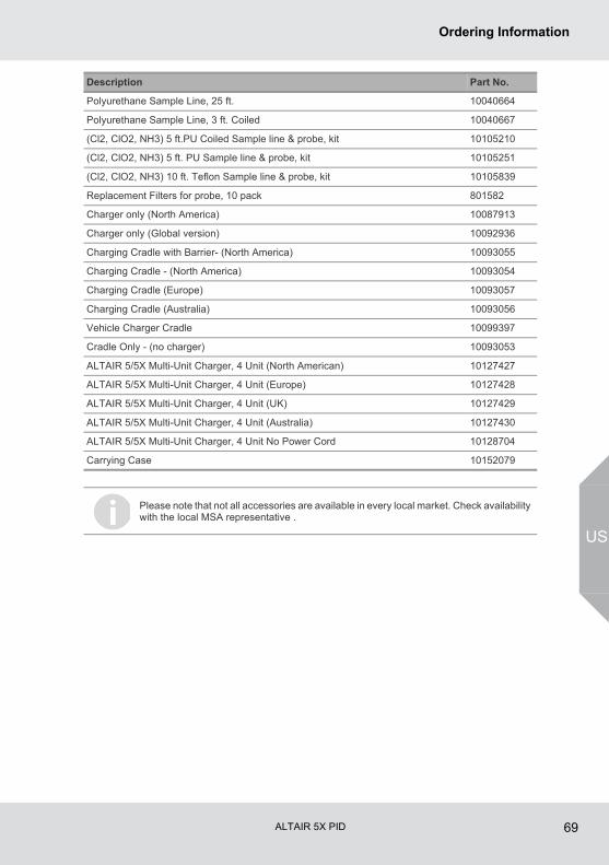
ALTAIR 5X PID 69
Ordering Information
US
Polyurethane Sample Line, 25 ft. 10040664
Polyurethane Sample Line, 3 ft. Coiled 10040667
(Cl2, ClO2, NH3) 5 ft.PU Coiled Sample line & probe, kit 10105210
(Cl2, ClO2, NH3) 5 ft. PU Sample line & probe, kit 10105251
(Cl2, ClO2, NH3) 10 ft. Teflon Sample line & probe, kit 10105839
Replacement Filters for probe, 10 pack 801582
Charger only (North America) 10087913
Charger only (Global version) 10092936
Charging Cradle with Barrier- (North America) 10093055
Charging Cradle - (North America) 10093054
Charging Cradle (Europe) 10093057
Charging Cradle (Australia) 10093056
Vehicle Charger Cradle 10099397
Cradle Only - (no charger) 10093053
ALTAIR 5/5X Multi-Unit Charger, 4 Unit (North American) 10127427
ALTAIR 5/5X Multi-Unit Charger, 4 Unit (Europe) 10127428
ALTAIR 5/5X Multi-Unit Charger, 4 Unit (UK) 10127429
ALTAIR 5/5X Multi-Unit Charger, 4 Unit (Australia) 10127430
ALTAIR 5/5X Multi-Unit Charger, 4 Unit No Power Cord 10128704
Carrying Case 10152079
Description Part No.
Please note that not all accessories are available in every local market. Check availability with the local MSA representative .

ALTAIR 5X PID 70
Ordering Information
US
Replacement Parts
4
7
6
1
2
8
5
3
9
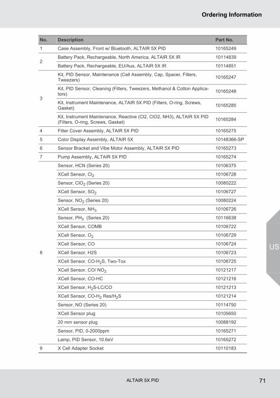
ALTAIR 5X PID 71
Ordering Information
US
No. Description Part No.
1 Case Assembly, Front w/ Bluetooth, ALTAIR 5X PID 10165249
2Battery Pack, Rechargeable, North America, ALTAIR 5X IR 10114839
Battery Pack, Rechargeable, EU/Aus, ALTAIR 5X IR 10114851
3
Kit, PID Sensor, Maintenance (Cell Assembly, Cap, Spacer, Filters, Tweezers)
10165247
Kit, PID Sensor, Cleaning (Filters, Tweezers, Methanol & Cotton Applica-tors)
10165248
Kit, Instrument Maintenance, ALTAIR 5X PID (Filters, O-ring, Screws, Gasket)
10165285
Kit, Instrument Maintenance, Reactive (Cl2, ClO2, NH3), ALTAIR 5X PID (Filters, O-ring, Screws, Gasket)
10165284
4 Filter Cover Assembly, ALTAIR 5X PID 10165275
5 Color Display Assembly, ALTAIR 5X 10148366-SP
6 Sensor Bracket and Vibe Motor Assembly, ALTAIR 5X PID 10165273
7 Pump Assembly, ALTAIR 5X PID 10165274
8
Sensor, HCN (Series 20) 10106375
XCell Sensor, Cl2 10106728
Sensor, ClO2 (Series 20) 10080222
XCell Sensor, SO2 10106727
Sensor, NO2 (Series 20) 10080224
XCell Sensor, NH3 10106726
Sensor, PH3 (Series 20) 10116638
XCell Sensor, COMB 10106722
XCell Sensor, O2 10106729
XCell Sensor, CO 10106724
XCell Sensor, H2S 10106723
XCell Sensor, CO-H2S, Two-Tox 10106725
XCell Sensor, CO/ NO2 10121217
XCell Sensor, CO-HC 10121216
XCell Sensor, H2S-LC/CO 10121213
XCell Sensor, CO-H2 Res/H2S 10121214
Sensor, NO (Series 20) 10114750
XCell Sensor plug 10105650
20 mm sensor plug 10088192
Sensor, PID, 0-2000ppm 10165271
Lamp, PID Sensor, 10.6eV 10165272
9 X Cell Adapter Socket 10110183
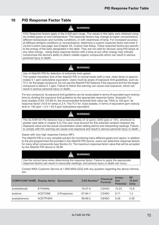
ALTAIR 5X PID 72
PID Response Factor Table
US
10 PID Response Factor Table
For any compound, its exposure limit guideline can be recalculated in terms of equivalent ppm isobuty-lene by dividing the exposure limit guideline by the appropriate response factor. Example: For butyl acetate (CAS 123-86-4), the recommended threshold limit value (as TWA) is 150 ppm. Its response factor (10.6 eV lamp) is 2.4. The TLV for butyl acetate, in terms of equivalent ppm isobuty-lene is: 150 ppm ÷ 2.4 = 62.5 ppm isobutylene equivalent.
Gases with very high response Factors (RF):The Altair5X PID is a very versatile solution for monitoring many different gases and vapors. In addition to the pre-programmed list provided in the Altair5X PID device, users can determine response factors for many other compounds (see Section X). The maximum response factor value that will be accepted by the Altair5X PID device is 39.99.
Contact MSA Customer Service at 1-800-MSA-2222 with any question regarding the above informa-tion.
WARNING
VOC Response factors apply in the 0-500 ppm range. The values in this table were obtained using dry bottled gases at room temperature. The response factors may change at higher concentrations, different temperature and humidity conditions, or with cleanliness of lamp. For increased accuracy at different ambient conditions or concentrations, determine a custom response factor and enter it via the Custom Gas page; see Chapter XX, Custom Gas Setup. These response factors are specific to the energy of the lamp designated in the table. They are not valid for devices using PID lamps at any other energy. Using these response factors with a lamp at any other energy may critically compromise the device's ability to detect volatile organic compounds which can result in serious personal injury or death.
WARNING
Use of Altair5X PID for detection of extremely toxic gases: The system resolution limit of the Altair5X PID in normal mode (with a new, clean lamp) is approxi-mately 0.1 ppm isobutylene equivalent. Users must be aware of exposure limit guidelines, such as TLV, for the target compound. Do not use the Altair5X PID Detector if the exposure limit for the target compound is below 0.1 ppm. Failure to follow this warning can cause over-exposure, which can result in serious personal injury or death.
WARNING
The ALTAIR 5X PID Detector has a reproducibility of ±2 ppm(± 2000 ppb) or 10%, whichever is greater (see table in chapter 6.2).The user must account for this potential variation between the displayed value and the actual concentration when setting alarms and interpreting readings. Failure to comply with this warning can cause over-exposure and result in serious personal injury or death.
WARNING
Use the correct lamp when determining the response factor. Failure to apply the appropriate response factors can result in inaccurate readings, and serious injury or death can occur.
COMPOUND NAME Display Name Synonym(s) CAS Number1 Chemical Formula
Ioniza-tion Potential
RF 10.6eV lamp
acetaldehyde ETHANAL 75-07-0 C2H4O 10.23 10.8
acetone ACETONE 2-Propanone 67-64-1 C3H6O 9.71 1.2
acetophenone ACETPHEN 98-86-2 C8H8O 9.28 0.59
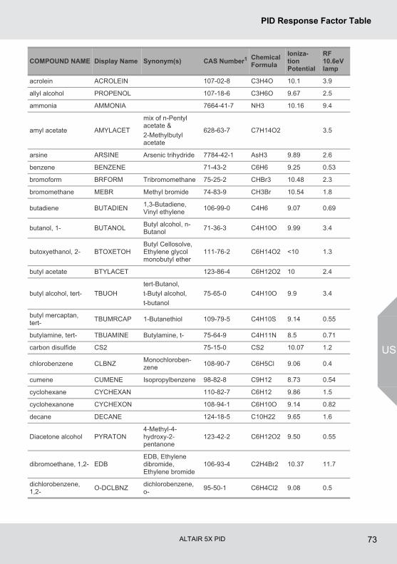
ALTAIR 5X PID 73
PID Response Factor Table
US
acrolein ACROLEIN 107-02-8 C3H4O 10.1 3.9
allyl alcohol PROPENOL 107-18-6 C3H6O 9.67 2.5
ammonia AMMONIA 7664-41-7 NH3 10.16 9.4
amyl acetate AMYLACET
mix of n-Pentyl acetate &
2-Methylbutyl acetate
628-63-7 C7H14O2 3.5
arsine ARSINE Arsenic trihydride 7784-42-1 AsH3 9.89 2.6
benzene BENZENE 71-43-2 C6H6 9.25 0.53
bromoform BRFORM Tribromomethane 75-25-2 CHBr3 10.48 2.3
bromomethane MEBR Methyl bromide 74-83-9 CH3Br 10.54 1.8
butadiene BUTADIEN1,3-Butadiene, Vinyl ethylene
106-99-0 C4H6 9.07 0.69
butanol, 1- BUTANOLButyl alcohol, n-Butanol
71-36-3 C4H10O 9.99 3.4
butoxyethanol, 2- BTOXETOHButyl Cellosolve, Ethylene glycol monobutyl ether
111-76-2 C6H14O2 <10 1.3
butyl acetate BTYLACET 123-86-4 C6H12O2 10 2.4
butyl alcohol, tert- TBUOH
tert-Butanol,
t-Butyl alcohol,
t-butanol
75-65-0 C4H10O 9.9 3.4
butyl mercaptan, tert-
TBUMRCAP 1-Butanethiol 109-79-5 C4H10S 9.14 0.55
butylamine, tert- TBUAMINE Butylamine, t- 75-64-9 C4H11N 8.5 0.71
carbon disulfide CS2 75-15-0 CS2 10.07 1.2
chlorobenzene CLBNZMonochloroben-zene
108-90-7 C6H5Cl 9.06 0.4
cumene CUMENE Isopropylbenzene 98-82-8 C9H12 8.73 0.54
cyclohexane CYCHEXAN 110-82-7 C6H12 9.86 1.5
cyclohexanone CYCHEXON 108-94-1 C6H10O 9.14 0.82
decane DECANE 124-18-5 C10H22 9.65 1.6
Diacetone alcohol PYRATON4-Methyl-4-hydroxy-2-pentanone
123-42-2 C6H12O2 9.50 0.55
dibromoethane, 1,2- EDBEDB, Ethylene dibromide, Ethylene bromide
106-93-4 C2H4Br2 10.37 11.7
dichlorobenzene, 1,2-
O-DCLBNZdichlorobenzene, o-
95-50-1 C6H4Cl2 9.08 0.5
COMPOUND NAME Display Name Synonym(s) CAS Number1 Chemical Formula
Ioniza-tion Potential
RF 10.6eV lamp
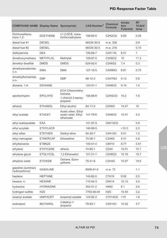
ALTAIR 5X PID 74
PID Response Factor Table
US
Dichloroethene, trans-1,2-
DCETHENEt-1,2-DCE, trans-Dichloroethylene
156-60-5 C2H2Cl2 9.65 0.45
diesel fuel #1 DIESEL 68334-30-5 m.w. 226 0.9
diesel fuel #2 DIESEL 68334-30-5 m.w. 216 0.75
diethylamine DEA 109-89-7 C4H11N 8.01 1
dimethoxymethane METHYLAL Methlylal 109-87-5 C3H8O2 10 11.3
dimethyl disulfide DMDS DMDS 624-92-0 C2H6S2 7.4 0.3
dimethylacetamide, n,n-
DMA DMA 127-19-5 C4H9NO 8.81 0.73
dimethylformamide, n,n-
DMF DMF 68-12-2 C3H7NO 9.13 0.8
dioxane, 1,4- DIOXANE 123-91-1 C4H8O2 9.19 1.4
epichlorhydrin EPCLHYD
ECH Chloromethy-loxirane,
1-chloro2,3-epoxy-propane
106-89-8 C2H5ClO 10.2 7.6
ethanol ETHANOL Ethyl alcohol 64-17-5 C2H6O 10.47 10
ethyl acetate ETACETAcetic ether; Ethyl acetic ester; Ethyl ethanoate
141-78-6 C4H8O2 10.01 4.2
ethyl acetoacetate EAA 141-97-9 C6H10O3 0.9
ethyl acrylate ETHYLACR 140-88-5 <10.3 2.3
ethyl ether ETETHER Diethyl ether 60-29-7 C4H10O 9.51 1.2
ethyl mercaptan ETMERCAP Ethanethiol 75-08-1 C2H6S 9.31 0.6
ethylbenzene ETBNZE 100-41-4 C8H10 8.77 0.51
ethylene ETHYLENE ethene 74-85-1 C2H4 10.51 10.1
ethylene glycol ETGLYCOL 1,2-Ethanediol 107-21-1 C2H6O2 10.16 15.7
ethylene oxide ETOXIDEOxirane, Epox-yethane
75-21-8 C2H4O 10.57 19.5
gasoline (summary hydrocarbons)
GASOLINE 8006-61-9 m.w. 72 1.1
heptane HEPTANE 142-82-5 C7H16 9.92 2.5
hexane, n- HEXANE 110-54-3 C6H14 10.13 4.5
hydrazine HYDRAZINE 302-01-2 H4N2 8.1 2.6
hydrogen sulfide H2S 7783-06-04 H2S 10.45 3.2
isoamyl acetate IAMYACET Isopentyl acetate 123-92-2 C7H14O2 <10 1.8
isobutanol IBUTANOL2-Methyl-1-propanol
78-83-1 C4H10O 10.02 4.7
COMPOUND NAME Display Name Synonym(s) CAS Number1 Chemical Formula
Ioniza-tion Potential
RF 10.6eV lamp
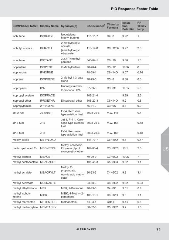
ALTAIR 5X PID 75
PID Response Factor Table
US
isobutene ISOBUTYLIsobutylene, Methyl butene
115-11-7 C4H8 9.22 1
isobutyl acetate IBUACET
2-methylpropyl acetate,
β-methylpropyl ethanoate
110-19-0 C6H12O2 9.97 2.6
isooctane IOCTANE2,2,4-Trimethyl-pentane
540-84-1 C8H18 9.86 1.3
isopentane ISOPENT 2-Methylbutane 78-78-4 C5H12 10.32 8
isophorone IPHORNE 78-59-1 C9H14O 9.07 0.74
isoprene ISOPRENE2-Methyl-1,3-buta-diene
78-79-5 C5H8 8.86 0.6
isopropanol IPAIsopropyl alcohol,
2-propanol, IPA67-63-0 C3H8O 10.12 5.6
isopropyl acetate ISOPRACE 108-21-4 9.99 2.6
isopropyl ether IPROETHR Diisopropyl ether 108-20-3 C6H14O 9.2 0.8
isopropylamine 2PRAMINE 75-31-0 C3H9N 8.6 0.9
Jet A fuel JETA(A1)F-34, Kerosene type aviation fuel
8008-20-6 m.w. 145 0.4
JP-5 fuel JP5Jet 5, F-4 4, Kero-sene type aviation fuel
8008-20-6 m.w. 167 0.48
JP-8 fuel JP8F-34, Kerosene type aviation fuel
8008-20-6 m.w. 165 0.48
mesityl oxide MSTYLOXD 141-79-7 C6H10O 9.1 0.47
methoxyethanol, 2- MEOXETOHMethyl cellosolve, Ethylene glycol monomethyl ether
109-86-4 C3H8O2 10.1 2.5
methyl acetate MEACET 79-20-9 C3H6O2 10.27 7
methyl acetoacetate MEACACET 105-45-3 C5H8O3 9.82 1.1
methyl acrylate MEACRYLT
Methyl 2-propenoate,
Acrylic acid methyl ester
96-33-3 C4H6O2 9.9 3.4
methyl benzoate MEBNZOTE 93-58-3 C8H8O2 9.32 0.93
methyl ethyl ketone MEK MEK, 2-Butanone 78-93-3 C4H8O 9.51 0.9
methyl isobutyl ketone
MIBKMIBK, 4-Methyl-2-pentanone
108-10-1 C6H12O 9.3 1.1
methyl mercaptan METHMERC Methanethiol 74-93-1 CH4 S 9.44 0.6
methyl methacrylate MEMEACRY 80-62-6 C5H8O2 9.7 1.5
COMPOUND NAME Display Name Synonym(s) CAS Number1 Chemical Formula
Ioniza-tion Potential
RF 10.6eV lamp
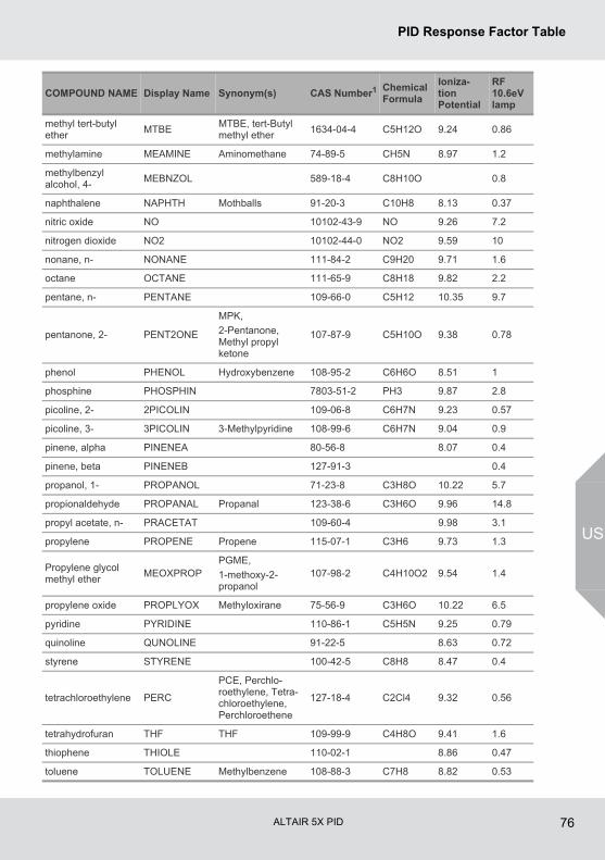
ALTAIR 5X PID 76
PID Response Factor Table
US
methyl tert-butyl ether
MTBEMTBE, tert-Butyl methyl ether
1634-04-4 C5H12O 9.24 0.86
methylamine MEAMINE Aminomethane 74-89-5 CH5N 8.97 1.2
methylbenzyl alcohol, 4-
MEBNZOL 589-18-4 C8H10O 0.8
naphthalene NAPHTH Mothballs 91-20-3 C10H8 8.13 0.37
nitric oxide NO 10102-43-9 NO 9.26 7.2
nitrogen dioxide NO2 10102-44-0 NO2 9.59 10
nonane, n- NONANE 111-84-2 C9H20 9.71 1.6
octane OCTANE 111-65-9 C8H18 9.82 2.2
pentane, n- PENTANE 109-66-0 C5H12 10.35 9.7
pentanone, 2- PENT2ONE
MPK,
2-Pentanone, Methyl propyl ketone
107-87-9 C5H10O 9.38 0.78
phenol PHENOL Hydroxybenzene 108-95-2 C6H6O 8.51 1
phosphine PHOSPHIN 7803-51-2 PH3 9.87 2.8
picoline, 2- 2PICOLIN 109-06-8 C6H7N 9.23 0.57
picoline, 3- 3PICOLIN 3-Methylpyridine 108-99-6 C6H7N 9.04 0.9
pinene, alpha PINENEA 80-56-8 8.07 0.4
pinene, beta PINENEB 127-91-3 0.4
propanol, 1- PROPANOL 71-23-8 C3H8O 10.22 5.7
propionaldehyde PROPANAL Propanal 123-38-6 C3H6O 9.96 14.8
propyl acetate, n- PRACETAT 109-60-4 9.98 3.1
propylene PROPENE Propene 115-07-1 C3H6 9.73 1.3
Propylene glycol methyl ether
MEOXPROPPGME,
1-methoxy-2-propanol
107-98-2 C4H10O2 9.54 1.4
propylene oxide PROPLYOX Methyloxirane 75-56-9 C3H6O 10.22 6.5
pyridine PYRIDINE 110-86-1 C5H5N 9.25 0.79
quinoline QUNOLINE 91-22-5 8.63 0.72
styrene STYRENE 100-42-5 C8H8 8.47 0.4
tetrachloroethylene PERC
PCE, Perchlo-roethylene, Tetra-chloroethylene, Perchloroethene
127-18-4 C2Cl4 9.32 0.56
tetrahydrofuran THF THF 109-99-9 C4H8O 9.41 1.6
thiophene THIOLE 110-02-1 8.86 0.47
toluene TOLUENE Methylbenzene 108-88-3 C7H8 8.82 0.53
COMPOUND NAME Display Name Synonym(s) CAS Number1 Chemical Formula
Ioniza-tion Potential
RF 10.6eV lamp
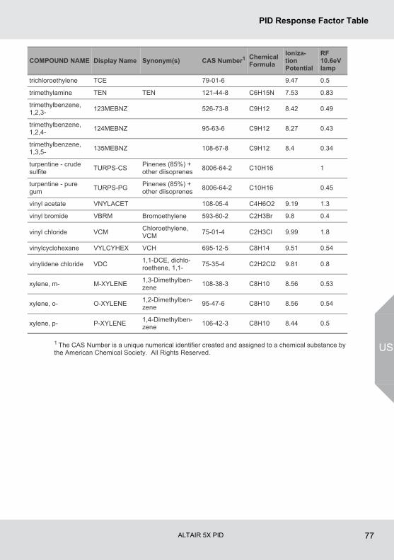
ALTAIR 5X PID 77
PID Response Factor Table
US1 The CAS Number is a unique numerical identifier created and assigned to a chemical substance by the American Chemical Society. All Rights Reserved.
trichloroethylene TCE 79-01-6 9.47 0.5
trimethylamine TEN TEN 121-44-8 C6H15N 7.53 0.83
trimethylbenzene, 1,2,3-
123MEBNZ 526-73-8 C9H12 8.42 0.49
trimethylbenzene, 1,2,4-
124MEBNZ 95-63-6 C9H12 8.27 0.43
trimethylbenzene, 1,3,5-
135MEBNZ 108-67-8 C9H12 8.4 0.34
turpentine - crude sulfite
TURPS-CSPinenes (85%) + other diisoprenes
8006-64-2 C10H16 1
turpentine - pure gum
TURPS-PGPinenes (85%) + other diisoprenes
8006-64-2 C10H16 0.45
vinyl acetate VNYLACET 108-05-4 C4H6O2 9.19 1.3
vinyl bromide VBRM Bromoethylene 593-60-2 C2H3Br 9.8 0.4
vinyl chloride VCMChloroethylene, VCM
75-01-4 C2H3Cl 9.99 1.8
vinylcyclohexane VYLCYHEX VCH 695-12-5 C8H14 9.51 0.54
vinylidene chloride VDC1,1-DCE, dichlo-roethene, 1,1-
75-35-4 C2H2Cl2 9.81 0.8
xylene, m- M-XYLENE1,3-Dimethylben-zene
108-38-3 C8H10 8.56 0.53
xylene, o- O-XYLENE1,2-Dimethylben-zene
95-47-6 C8H10 8.56 0.54
xylene, p- P-XYLENE1,4-Dimethylben-zene
106-42-3 C8H10 8.44 0.5
COMPOUND NAME Display Name Synonym(s) CAS Number1 Chemical Formula
Ioniza-tion Potential
RF 10.6eV lamp

ALTAIR 5X PID 78
Flow Charts
US
11 Flow Charts11.1 Basic Operation
TURN OFF
FRESH AIRSETUP ?
SENSORDISCOVERY
INSTRUMENTINFORMATION
PUMP TEST
InstantAlertTM *
For 5seconds
BUMP TEST /INFORMATIONAL
PAGESCALIBRATE
SETUP
MAINMEASURE
PAGE
For 5seconds
For 5seconds
SENSOR ANDCALIBRATIONINFORMATION
* IF ENABLED
Hold andSimultaneouslyfor 5 seconds
Hold
Hold
Press
Hold
TURN-ON ORBATTERYATTACH
BLUETOOTHINFORMATION
(See 11.3)
(See 11.4)
(See 11.2)
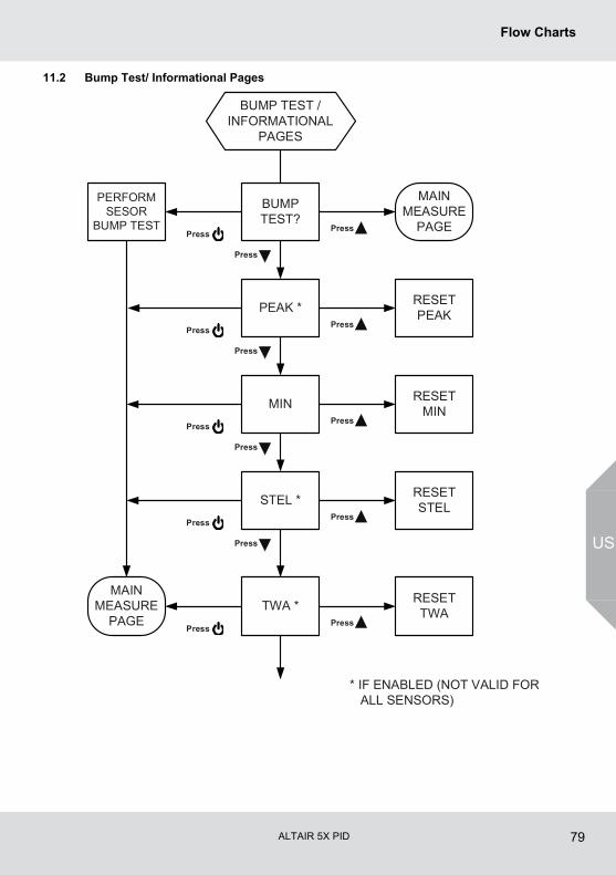
ALTAIR 5X PID 79
Flow Charts
US
11.2 Bump Test/ Informational Pages
PEAK * RESETPEAK
MIN RESETMIN
STEL * RESETSTEL
TWA * RESETTWA
BUMP TEST /INFORMATIONAL
PAGES
BUMPTEST?
PERFORMSESOR
BUMP TEST
MAINMEASURE
PAGE
MAINMEASURE
PAGE
* IF ENABLED (NOT VALID FOR ALL SENSORS)
Press
Press
Press
Press
Press
Press
Press
Press
Press
Press
Press
Press
Press
Press
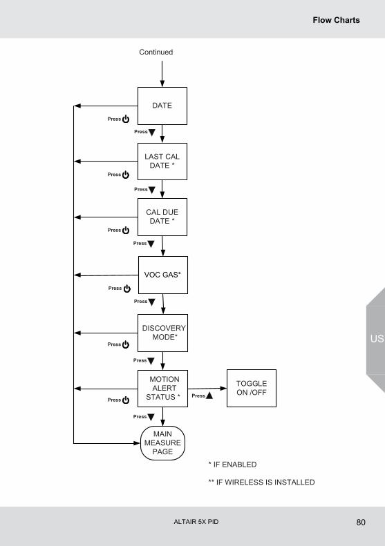
ALTAIR 5X PID 80
Flow Charts
US
DATE
LAST CALDATE *
CAL DUEDATE *
Continued
* IF ENABLED
** IF WIRELESS IS INSTALLED
Press
Press
Press
Press
Press
TOGGLEON /OFF
Press
Press
Press
Press
MAINMEASURE
PAGE
Press
Press
Press
Press
MOTIONALERT
STATUS *
DISCOVERY MODE*
VOC GAS*
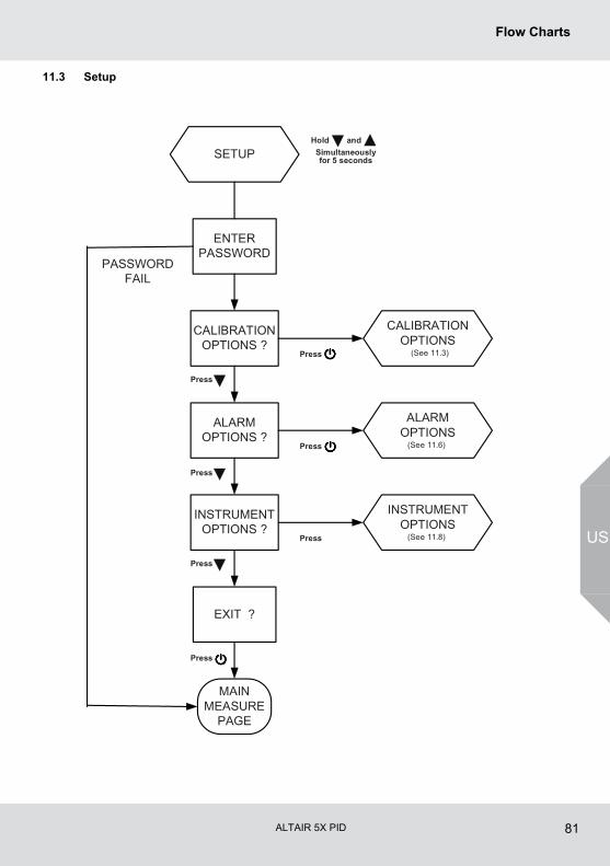
ALTAIR 5X PID 81
Flow Charts
US
11.3 Setup
ENTERPASSWORD
EXIT ?
PASSWORDFAIL
SETUP
ALARMOPTIONS
(See 11.6)
INSTRUMENTOPTIONS
(See 11.8)
CALIBRATIONOPTIONS
(See 11.3)
CALIBRATIONOPTIONS ?
ALARMOPTIONS ?
INSTRUMENTOPTIONS ?
MAINMEASURE
PAGE
Press
Press
Press
Press
Press
Press
Press
Hold andSimultaneouslyfor 5 seconds
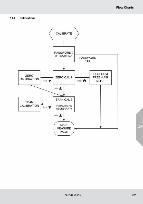
ALTAIR 5X PID 82
Flow Charts
US
11.4 Calibrations
PASSWORD ?(IF REQUIRED)
ZERO CAL ?
SPAN CAL ?
(REPEATS ASNECESSARY)
PASSWORDFAIL
CALIBRATE
MAINMEASURE
PAGE
ZEROCALIBRATION
Press
PERFORMFRESH AIR
SETUPPress
Press
SPANCALIBRATION
Press
Press
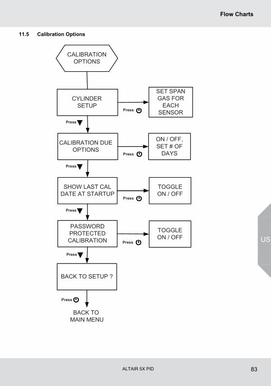
ALTAIR 5X PID 83
Flow Charts
US
11.5 Calibration Options
CYLINDERSETUP
CALIBRATION DUEOPTIONS
SHOW LAST CALDATE AT STARTUP
PASSWORDPROTECTEDCALIBRATION
BACK TO SETUP ?
CALIBRATIONOPTIONS
TOGGLEON / OFF
TOGGLEON / OFF
ON / OFF,SET # OF
DAYS
SET SPANGAS FOR
EACHSENSOR
BACK TO MAIN MENU
Press
Press
Press
Press
Press
Press
Press
Press
Press
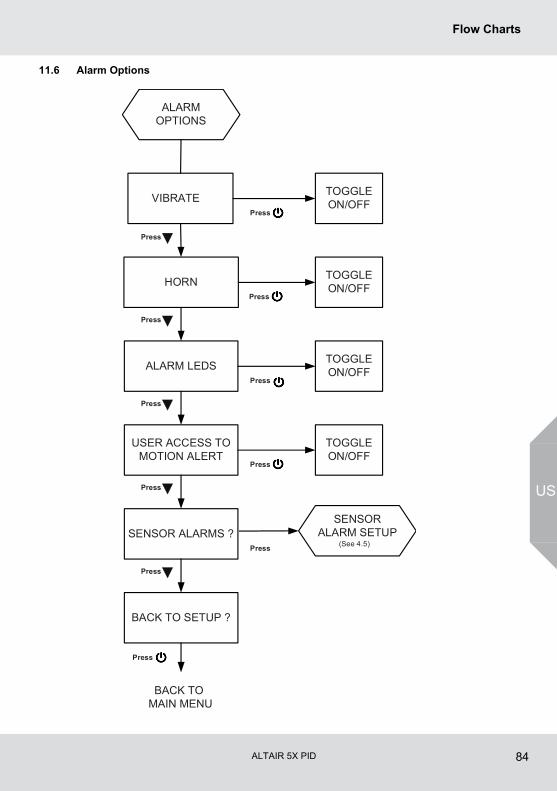
ALTAIR 5X PID 84
Flow Charts
US
11.6 Alarm Options
VIBRATE
HORN
ALARM LEDS
USER ACCESS TOMOTION ALERT
SENSOR ALARMS ?
ALARMOPTIONS
TOGGLEON/OFF
BACK TO SETUP ?
SENSORALARM SETUP
(See 4.5)
TOGGLEON/OFF
TOGGLEON/OFF
TOGGLEON/OFF
BACK TO MAIN MENU
Press
Press
Press
Press
Press
Press
Press
Press
Press
Press
Press
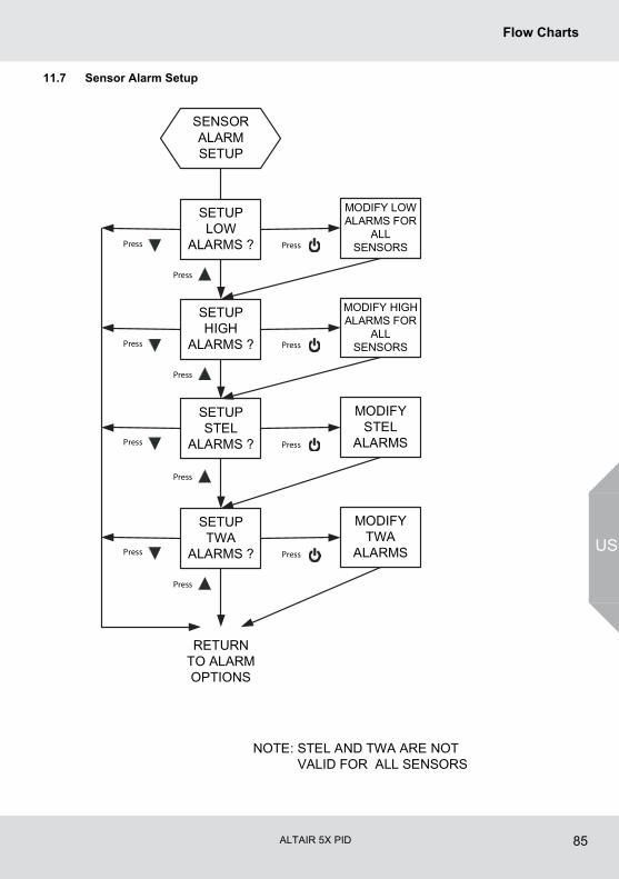
ALTAIR 5X PID 85
Flow Charts
US
11.7 Sensor Alarm Setup
SETUPLOW
ALARMS ?
MODIFY LOWALARMS FOR
ALLSENSORS
SETUPHIGH
ALARMS ?
MODIFY HIGHALARMS FOR
ALLSENSORS
SETUPSTEL
ALARMS ?
MODIFYSTEL
ALARMS
SETUPTWA
ALARMS ?
MODIFYTWA
ALARMS
SENSORALARMSETUP
RETURNTO ALARMOPTIONS
NOTE: STEL AND TWA ARE NOT VALID FOR ALL SENSORS
Press
Press
Press
Press
Press
Press
Press
Press
Press
Press
Press
Press
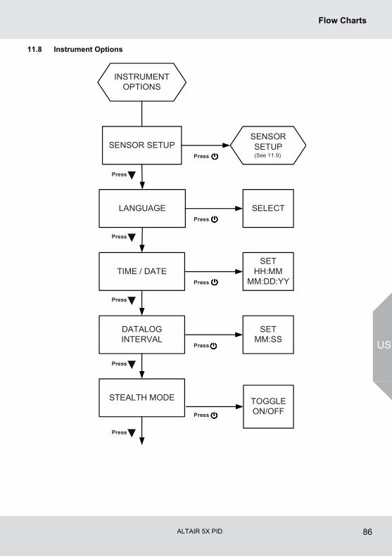
ALTAIR 5X PID 86
Flow Charts
US
11.8 Instrument Options
SENSOR SETUP
LANGUAGE
TIME / DATE
DATALOGINTERVAL
STEALTH MODE
INSTRUMENTOPTIONS
SELECT
SETHH:MM
MM:DD:YY
SETMM:SS
TOGGLEON/OFF
Press
Press
Press
Press
Press
Press
Press
Press
Press
Press
SENSORSETUP(See 11.9)
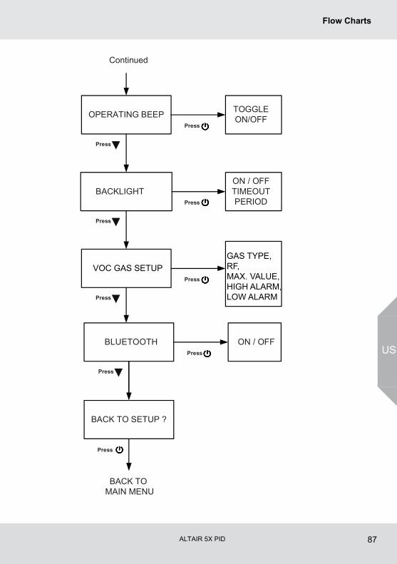
ALTAIR 5X PID 87
Flow Charts
US
BACKLIGHTON / OFFTIMEOUTPERIOD
OPERATING BEEP TOGGLEON/OFF
Continued
Press
Press
Press
Press
Press
Press
BACK TO SETUP ?
BACK TO MAIN MENU
Press
BLUETOOTH
Press
ON / OFFPress
VOC GAS SETUPGAS TYPE, RF,MAX. VALUE, HIGH ALARM, LOW ALARM
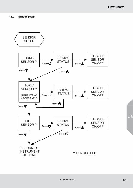
ALTAIR 5X PID 88
Flow Charts
US
11.9 Sensor Setup
COMBSENSOR **
TOXICSENSOR **
(REPEATS ASNECESSARY)
SENSORSETUP
RETURN TOINSTRUMENT
OPTIONS
Press
Press
Press
SHOWSTATUS
Press
TOGGLESENSORON/OFF
TOGGLESENSORON/OFF
SHOWSTATUS
Press
PIDSENSOR **
SHOWSTATUS
TOGGLESENSORON/OFFPress
** IF INSTALLED
Press
Press
Press
Press
Press
Press
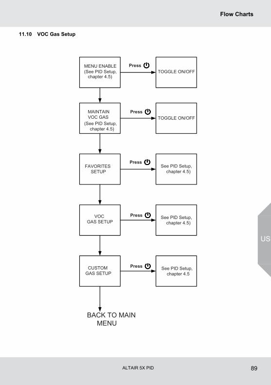
ALTAIR 5X PID 89
Flow Charts
US
11.10 VOC Gas Setup
MENU ENABLE(See PID Setup,
chapter 4.5)
MAINTAIN VOC GAS
(See PID Setup, chapter 4.5)
FAVORITES SETUP
VOC GAS SETUP
CUSTOM GAS SETUP
BACK TO MAIN MENU
TOGGLE ON/OFF
TOGGLE ON/OFF
See PID Setup, chapter 4.5)
See PID Setup, chapter 4.5)
See PID Setup, chapter 4.5
Press
Press
Press
Press
Press
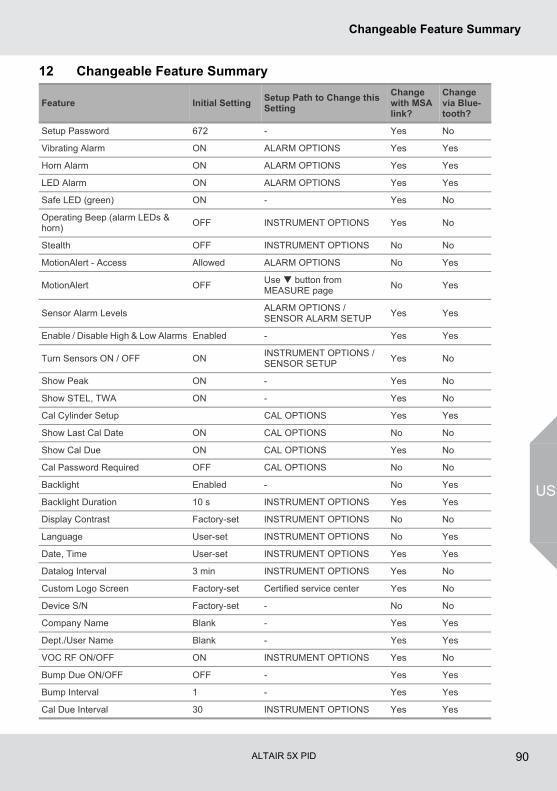
ALTAIR 5X PID 90
Changeable Feature Summary
US
12 Changeable Feature Summary
Feature Initial SettingSetup Path to Change this Setting
Change with MSA link?
Change via Blue-tooth?
Setup Password 672 - Yes No
Vibrating Alarm ON ALARM OPTIONS Yes Yes
Horn Alarm ON ALARM OPTIONS Yes Yes
LED Alarm ON ALARM OPTIONS Yes Yes
Safe LED (green) ON - Yes No
Operating Beep (alarm LEDs & horn)
OFF INSTRUMENT OPTIONS Yes No
Stealth OFF INSTRUMENT OPTIONS No No
MotionAlert - Access Allowed ALARM OPTIONS No Yes
MotionAlert OFFUse button from MEASURE page
No Yes
Sensor Alarm LevelsALARM OPTIONS / SENSOR ALARM SETUP
Yes Yes
Enable / Disable High & Low Alarms Enabled - Yes Yes
Turn Sensors ON / OFF ONINSTRUMENT OPTIONS / SENSOR SETUP
Yes No
Show Peak ON - Yes No
Show STEL, TWA ON - Yes No
Cal Cylinder Setup CAL OPTIONS Yes Yes
Show Last Cal Date ON CAL OPTIONS No No
Show Cal Due ON CAL OPTIONS Yes No
Cal Password Required OFF CAL OPTIONS No No
Backlight Enabled - No Yes
Backlight Duration 10 s INSTRUMENT OPTIONS Yes Yes
Display Contrast Factory-set INSTRUMENT OPTIONS No No
Language User-set INSTRUMENT OPTIONS No Yes
Date, Time User-set INSTRUMENT OPTIONS Yes Yes
Datalog Interval 3 min INSTRUMENT OPTIONS Yes No
Custom Logo Screen Factory-set Certified service center Yes No
Device S/N Factory-set - No No
Company Name Blank - Yes Yes
Dept./User Name Blank - Yes Yes
VOC RF ON/OFF ON INSTRUMENT OPTIONS Yes No
Bump Due ON/OFF OFF - Yes Yes
Bump Interval 1 - Yes Yes
Cal Due Interval 30 INSTRUMENT OPTIONS Yes Yes

For local MSA contacts, please visit us at MSAsafety.com
Because every life has a purpose...