operation manual - cole-parmer · operation manual laboratory - vacuum - system type lvs 110 tp...
TRANSCRIPT

Operation Manual
Laboratory - Vacuum - System
Type LVS 110 Tp ecoflex
113184 2008-05-21
We are constantly working on the further development of all our product types. Reprinting or reproduction of this manual, including extracts, is not allowed without the prior written permission of ILMVAC GmbH. All rights under the copyright laws are expressly reserved by ILMVAC GmbH. We reserve the right to make changes and amendments. ILMVAC GmbH Am Vogelherd 20 98693 Ilmenau, Germany Telephone: +49 36 77 60 40 Fax: +49 36 77 60 41 10 E-mail: [email protected] Internet: http://www.ilmvac.de http://www.ilmvac.com

Contents
Contents
1 Important Information.............................................................................................................5 1.1 General Information ..................................................................................................................5 1.2 Target Groups...........................................................................................................................5 1.3 Intended Use.............................................................................................................................5 1.4 Use for an Unauthorized Purpose ............................................................................................5 1.5 Safety Devices ..........................................................................................................................6 1.6 Meaning of the Warning notes ..................................................................................................6 1.7 Product Standards, Safety Regulations....................................................................................6 2 Basic Safety Instructions .......................................................................................................7 2.1 General Information ..................................................................................................................7 2.2 Electricity...................................................................................................................................7 2.3 Mechanical Systems .................................................................................................................8 2.4 High Temperatures ...................................................................................................................8 2.5 Hazardous Substances.............................................................................................................9 3 Description ............................................................................................................................10 3.1 Design and Function ...............................................................................................................10 3.1.1 Laboratory-Vacuum-System ...................................................................................................10 3.1.2 Diaphragm pump ....................................................................................................................11 3.1.3 Vacuum Controller ..................................................................................................................11 3.1.4 Additional Operating pad ........................................................................................................12 3.2 Areas of Application ................................................................................................................12 3.3 Scope of Delivery....................................................................................................................12 3.4 Example of application............................................................................................................12 3.5 Accessories.............................................................................................................................13 4 Technical Data.......................................................................................................................14 4.1 View of device and dimensions...............................................................................................14 4.2 Intake Pressure / Pumping Speed – Diagram ........................................................................14 4.3 Device data .............................................................................................................................15 5 Assembly and Installation....................................................................................................16 5.1 Unpacking ...............................................................................................................................16 5.2 Installation and Connection.....................................................................................................16 5.2.1 General instructions ................................................................................................................16 5.3 Storage....................................................................................................................................17 5.4 Scrap Disposal ........................................................................................................................17 6 Operation ...............................................................................................................................18 6.1 Control panel...........................................................................................................................18 6.1.1 Starting up...............................................................................................................................18 6.2 Operating modes of the Controller..........................................................................................19 6.2.1 Selection, display of operating modes ....................................................................................20 6.2.2 Setting / changing the control parameters at the controller ....................................................20 6.2.3 Setting the selected control parameters .................................................................................21 6.2.4 Querying the set values ..........................................................................................................21 6.2.5 Changing the pressure during operation ................................................................................21 6.2.6 Set minimum pressure ............................................................................................................21 6.2.7 Venting the system .................................................................................................................21 6.2.8 Setting the after-running time for the cooling water ................................................................22 6.3 Calibration...............................................................................................................................22 6.3.1 Run via control panel ..............................................................................................................22
113184 3

Contents 6.4 Operation using the "ILMVAC-Control" .................................................................................. 23 6.4.1 Menu item: „File“ .................................................................................................................... 25 6.4.2 Menu item: „Settings!“ ............................................................................................................ 26 6.4.3 Menu item: „Alarm“................................................................................................................. 28 6.4.4 Menu item: „Calibrate“............................................................................................................ 29 6.4.5 Menu item: „Factory settings“................................................................................................. 30 6.4.6 Operation via RS 485 (according to NAMUR NE 28) ............................................................ 31 6.5 Table of solvents .................................................................................................................... 32 7 Maintenance and Servicing................................................................................................. 33 7.1 General Requirements ........................................................................................................... 33 7.2 Maintenance Performed by the User ..................................................................................... 33 7.2.1 Maintenance of the diaphragm pump..................................................................................... 33 7.2.1.1 Disassembly ........................................................................................................................... 34 7.2.1.2 Assembly................................................................................................................................ 35 7.2.1.3 Test......................................................................................................................................... 36 7.2.2 Maintenance of the vacuum controller ................................................................................... 36 7.2.3 Maintenance of other components......................................................................................... 36 7.3 Maintenance by the Manufacturer.......................................................................................... 36 7.4 Damage Report ...................................................................................................................... 36 8 Troubleshooting ................................................................................................................... 37 9 Spare Parts Overview .......................................................................................................... 38 9.1 Maintenance kit - Diaphragm Pump....................................................................................... 38 9.2 Exploded view - LVS 110 Tp ecoflex ..................................................................................... 39 9.2.1 Spare parts list - LVS 110 Tp ecoflex.................................................................................... 40
4 113184
Important Information
1 Important Information
1.1 General Information The ILMVAC Laboratory-Vacuum-System LVS 110 Tp ecoflex conform to the • 2006/95/EC Low Voltage Directive • 2006/42/EC Machinery Directive • 2004/108/EC Electromagnetic Compatibility Directive
The CE sign is located on the rating plate. Observe the binding national and local regulations when fitting the pump into installations. Our products are sold worldwide and can therefore be equipped with the typical national plugs and for the various voltages. You will find more information about the available designs under http://www.ilmvac.de.
1.2 Target Groups This Operating Manual is intended for the personnel planning, operating and maintaining ILMVAC Laboratory-Vacuum-Systems. This group of people includes: • Designers and fitters of vacuum apparatus, • Employees working on commercial laboratory and industrial vacuum technology applications and • Service personnel for laboratory-vacuum-system LVS 110 Tp ecoflex.
The personnel operating and maintaining the laboratory vacuum systems must have the technical competence required to perform the work that has to be done. The user must authorize the operating personnel to do the work that has to be done. The personnel must have read and understood the complete Operating Manual before using the laboratory-vacuum-systems. The Operating Manual must be kept at the place of use and be available to the personnel when required.
1.3 Intended Use • The laboratory-vacuum-system may only be operated under the conditions stated
– in the "Technical Data" section, – on the type plate, and – in the technical specification for the order concerned.
• Laboratory-vacuum-systems are approved for extracting, pumping and compressing gases and va-pours. If these gases and vapours are toxic or explosive, then the user must observe the currently valid safety regulations for this application. Special types of diaphragm pumps are available for ag-gressive and explosive gases.
• Laboratory-vacuum-systems are intended for generating vacuums with ultimate pressures of around 2 mbar.
• The in-built diaphragm pump has been designed to have high resistance to aggressive gases. • The active heating of the pump heads eliminates the need for a gas ballast valve.
1.4 Use for an Unauthorized Purpose It is forbidden to use the pump for applications deviating from the technical data stated on the type plate or the conditions stated in the supply contract, or to operate it with missing or defective protective devices.
113184 5
Important Information
1.5 Safety Devices – Measures such as the following are for the safety of the operating personnel:
• electrical connection with a protective conductor (operating mode S1) and an earthing plug, • fine-wire fuse (slow-blow),
• “Hot Surface" label on the pump body (warning notice), • completely enclosed casing, • identification WEEE, • glass components with a transparent plastic coating which protects them against bursting and
cracking, cooler isolated. The laboratory-vacuum-system must not be operated without these elements.
1.6 Meaning of the Warning notes Take note of the warning notices. They are in the following box:
CAUTION ! / WARNING !
Hazard which may lead to serious injuries or material damage.
1.7 Product Standards, Safety Regulations ILMVAC LVS 110 Tp ecoflex meet the following product standards:
DIN EN 292-1, DIN EN 292-2 Safety of machines, basic terminology DIN EN 1012-2 Compressors and vacuum pumps DIN EN 60204-1 Electrical equipment of machines EN 50110-1 (DIN VDE 0105-100) Operation of electrical installations EN 61010-1 Safety for laboratory devices EN 50081-1-2 Electromagnetic compatibility (EMC)
Generic specification - Interference resistance for residential, business and industrial areas, and small businesses
EN 50082-1-2 Electromagnetic compatibility (EMC) Generic specification - Interference emission for residential, business and industrial areas, and small businesses
EN 55014 Radio disturbance characteristics of electrical equipment and systems
EN 61000-3-2/3 Electromagnetic compatibility (EMC)
Directive 2006/42/EC Law and Administration Regulations relating to Machinery Directive 2002/95/EC RoHS Restriction of use of certain hazardous substances
The following additional safety regulations apply in the FR Germany:
BGV A2 Electrical equipment and operating materials VBG 5 Power-driven machines BGR 120 Guidelines for laboratories BGI 798 BG hazard assessment in the laboratory
Observe the standards and regulations applying in your country when you use the LVS.
6 113184
Basic Safety Instructions
2 Basic Safety Instructions
2.1 General Information
CAUTION !
Warning notices must be observed. Disregarding them may lead to damage to health and property.
The laboratory vacuum systems must be operated by personnel who can detect impending dangers and take action to prevent them from materialising. The user/operator is responsible for correct installation and safe operation. Prevent condensate collecting in the pump. When pumping vapours which tend to condense, please ensure that the pump is at operating temperature and that the gas ballast valve is o-pen when the pump is switched on. If there is more than one load on one LVS, they must be separated by check valves. The manufacturer or authorized authorised workshops will only service or maintain the labo-ratory vacuum system if it is accompanied by a fully completed damage report. Precise in-formation about the contamination (also negative information if necessary) and thorough cleaning of the laboratory vacuum system are legally binding parts of the contract. Contaminated laboratory vacuum systems and their individual parts must be disposed of in accordance with the legal regulations. The local regulations apply in foreign countries.
2.2 Electricity The LVS 110 Tp ecoflex are supplied for operating mode S1. Please note that the testing must be repeated in accordance with DIN EN 0105, DIN EN 0702 and BGV A2 in case of portable devices. The local regulations apply in foreign countries. Please note the following when connecting to the electrical power supply system: • The electrical power supply system must have a protective connector according to DIN VDE 0100-
410 (IEC 60364-4-41). • The protective connector must not have any breaks.
• The connecting cable must not be damaged. • All interfaces are under low voltage according to DIN VDE 0100-410.
113184 7
Basic Safety Instructions
2.3 Mechanical Systems Improper use can lead to injuries or material damage. Observe the following instructions: • Only operate the LVS with hoses of the specified dimensions. • The maximum permissible pressure of 1 bar at the suction connection must not be exceeded. • Solid particles in the pumping medium impair the pumping action and can lead to damage. Prevent
solid particles penetrating into the pump. • Hazardous substances must be separated out as far as this is technically possible before they
reach the pump. • External mechanical stresses and vibrations must not be transmitted to the pump. Only use flexible
laboratory hoses for connecting laboratory vacuum systems.
• The overpressure generated at the pressure port must not exceed 1 bar. • The pump must not be used to suck up fluids. Lay the exhaust pipe so that it slopes downwards, so
allowing condensate to flow out of the pump. Collect the condensate and dispose of it in an envi-ronmentally compatible manner.
When handling glass vessels, pay attention to: • Only use glass vessels with a plastic coating for splinter protection. • Only use vessels which are suitable for use with vacuums (e.g. round-bottomed flasks).
We recommend that only glass components supplied by the manufacturer are used. Do not use Erlenmeyer flasks.
• Before each evacuation, check glass vessels for damage which might impair their strength, replace them if any such damage is found.
• Do not heat glass vessels on one side only. • Retardation of the boiling of the gases to be pumped can lead to a sudden pressure increase. Pre-
vent retardation of boiling by means of suitable measures (e.g. turbulent agitation).
2.4 High Temperatures Prevent the following maximum permissible temperatures from being exceeded. • + 40 °C for the environment, and • + 60 °C for the gas to be pumped. The motor for single phase alternating current is protected against overload by an integrated motor protection switch.
8 113184

Basic Safety Instructions
2.5 Hazardous Substances
WARNING !
The operating company bears the responsibility for the use of the laboratory vacuum system.
Hazardous and harmful substances must be effectively prevented from escaping! Ensure that all lines and connections are leak tight. Handle exhaust gases in accordance with the requirements of the emission protection regu-lations. Do not operate the laboratory vacuum system without a separator. The separator can only be emptied after the apparatus has been vented. Dispose the condensate in an environmentally compatible manner! The emission condenser has a safety valve. The air evacuation duct with hose must be kept clear and lead into a suitable air evacuation duct. Throttling the air evacuation duct can da-mage the valves of the diaphragm pump. Hazardous substances in the gases to be pumped can cause personal injuries and property damage. Pay attention to the warning notices for handling hazardous substances. The local regulations apply in foreign countries. Combustible Gases The user must assess the process in accordance with Directive 1999/92/EC (ATEX 137) for the extraction of explosive gas/air mixtures inside or outside a similar environment. In accor-dance with the requirements indicated by this assessment, a suitable device must be se-lected which fulfils the specifications of Directive 94/9/EC (ATEX 95). Aggressive gases The diaphragm pump used is highly resistant to chemicals. In the case of particularly ag-gressive gases or products, the materials used for the pump parts in contact with gas must be assessed (as described in chapter 3.1.2). Poisonous gases Use a separator when pumping poisonous or harmful gases. Prevent such substances from leaking out of the appliance or pump. Treat these substances according to the applicable environmental protection regulations. The diaphragm pump, control valves and hose lines can be damaged by poisonous or ag-gressive gases. Test the strength and leak-tightness of the connecting lines and the connected apparatus. Prevent environmental poisons, e.g. mercury, getting into the diaphragm pumps. Fulfil the requirements, for example: • German Hazardous Substances Regulation (GefStoffV) of 23. December 2004
• Regulations 2006/121/EC (classification, packaging and identification of hazardous substances), • Manufacturer's safety data sheets on hazardous substances.
113184 9

Description
3 Description
3.1 Design and Function
3.1.1 Laboratory-Vacuum-System A rotary evaporator can achieve its full performance capability as a result of precisely controlled, ana-lytically pure vacuum. The Laboratory Vacuum System “LVS 110 Tp ecoflex” has been specifically designed to meet these requirements. The chemically resistant diaphragm pump “MPC 104 Tp” provides an oil-free, dry and thus analytically pure vacuum to an ultimate pressure of < 2 mbar. The maximum pumping speed of 1.1 m3/h is matched directly to the actual requirement by the speed control of the powerful and extremely quiet 24 V EC drive of the diaphragm pump. The LVS thus always works optimally. With a high quantity of gas under full power = maximum speed, with a low quantity of gas correspondingly slower. That protects the diaphragm pump, reduces the al-ready low energy consumption, and considerably reduces the noise level. At the same time, this de-sired reduction of the stroke rate leads to a reduction of the pump temperature and to increased con-densation. To prevent this, the pump heads are held at a constant temperature by a control system. Investigations have shown that this eliminates the need for a gas ballast valve. A gas ballast valve (see chapter 3.5) can be optionally mounted if this is not possible under certain conditions. The new design, the functional and well-arranged structure, and the smaller dimensions allow trouble-free, time-saving cleaning. A second operating console (operating pad) can easily be connected for remote control of the LVS 110 Tp ecoflex, for example for working in the extraction hood or in other critical areas. The LVS 110 Tp ecoflex is supplied complete with a suction-side separator and a pressure-side emis-sion condenser in the form of an intensive cooler.
1 Suction side connection
hose nozzle for hose DN8
2 Separator (round-bottomed flask) suction side
3 Casing Diaphragm pump MPC (fitted in the casing) with main switch
4 Control level Vacuum Controller with integrated grip recess
5 Emission condenser KD 500/5 insulated at the pressure side with safety valve and cooling water connections, outgoing air connection (hose nozzle for hose DN8)
Fig. 1a LVS 110 Tp ecoflex - Front view 6 Separator (round-bottomed flask) outgoing air side
7 Cooling water (feed flow / back flow)
8 Connection outgoing air hose nozzle for hose DN8
9 Main switch (Power)
10 Main device fuse
11 Plug for non-heating device power cable (Main in)
12 PC connector (RS 232)
13 Connector socket for operating pad (optional)
14 Connector socket for water valve (optional)
15 Inert gas connection DN 4
Fig. 1b LVS 110 Tp ecoflex - Rear view
10 113184
Description 3.1.2 Diaphragm pump
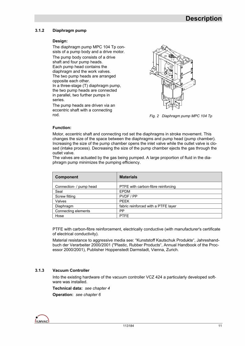
Design: The diaphragm pump MPC 104 Tp con-sists of a pump body and a drive motor. The pump body consists of a drive shaft and four pump heads. Each pump head contains the diaphragm and the work valves. The two pump heads are arranged opposite each other. In a three-stage (T) diaphragm pump, the two pump heads are connected in parallel, two further pumps in series. The pump heads are driven via an eccentric shaft with a connecting rod.
Fig. 2 Diaphragm pump MPC 104 Tp
Function: Motor, eccentric shaft and connecting rod set the diaphragms in stroke movement. This changes the size of the space between the diaphragms and pump head (pump chamber). Increasing the size of the pump chamber opens the inlet valve while the outlet valve is clo-sed (intake process). Decreasing the size of the pump chamber ejects the gas through the outlet valve. The valves are actuated by the gas being pumped. A large proportion of fluid in the dia-phragm pump minimizes the pumping efficiency.
Component Materials
Connection- / pump head PTFE with carbon-fibre reinforcing Seal EPDM Screw fitting PVDF / PP Valves PEEK Diaphragm fabric reinforced with a PTFE layer Connecting elements PP Hose PTFE
PTFE with carbon-fibre reinforcement, electrically conductive (with manufacturer's certificate of electrical conductivity). Material resistance to aggressive media see: “Kunststoff Kautschuk Produkte“, Jahreshand-buch der Verarbeiter 2000/2001 ("Plastic, Rubber Products“, Annual Handbook of the Proc-essor 2000/2001), Publisher Hoppenstedt Darmstadt, Vienna, Zurich.
3.1.3 Vacuum Controller Into the existing hardware of the vacuum controller VCZ 424 a particularly developed soft-ware was installed. Technical data: see chapter 4 Operation: see chapter 6
113184 11

Description 3.1.4 Additional Operating pad
The controlled LVS can be ordered with a separate operating pad in order to be able to op-erate it from an external keypad. It is also possible to connect the operating pad to an exist-ing device at a later date. In order to do this, the optionally supplied operating pad has to be purchased under order no. 113513. It is then activated by a one-off registration via the PC program "ILMVAC-Control" (display address: mount 1 on 2) see chapter 6.4.5).
3.2 Areas of Application The LVS 110 Tp ecoflex is intended for: • vacuum filtration, vacuum distillation and vacuum drying. • use in physical and chemical laboratories in trade and industry. • pumping and compressing neutral and aggressive gases and vapours.
• generating a vacuum up to an ultimate pressure of around 2 mbar without using the lubricant oil. Special designs: • Special LVS can be supplied after consultation with the manufacturer or for a corresponding supply
contract.
• Motors for different voltages.
3.3 Scope of Delivery The scope of delivery is specified in the supply contract.
3.4 Example of application
1 LVS 110 Tp ecoflex 4 Rotary vaporizer * 2 Suction line * 5 Coolant system, un pressurised run back * 3 Outgoing air 6 Water valve WV *
Fig. 3 Example of application – LVS 110 Tp ecoflex * Not included in the scope of delivery
12 113184

Description
3.5 Accessories
Vacuum Control-Box VCB 424 cv Table model as digital, chemical-resistant vacuum regulator. With integrated sensor, airing -, control- and check valve. Connection vacuum apparatus: DN 8 Connection vacuum pump: DN 8 Connection inert gas: DN 4 Connection water valve: Binder plug 4-pole 24V DC Order no. 600037
Operating pad complete – VCZ 424 For external operation with a controlled laboratory vacuum system. (maximum distance from basic device, approx. 3 m) Order no. 113513
+ CD
"ILMVAC-Control" operating software with the dual data cable VCZ 424
to connect the vacuum controller to the PC
Order no. 620617
Gas ballast valve (as from series 08/2007) Order no. 400599-01
113184 13
Technical Data
4 Technical Data
4.1 View of device and dimensions
(W)
(H)
(D)
Fig. 4 View of device and dimensions (see chapter 4.3)
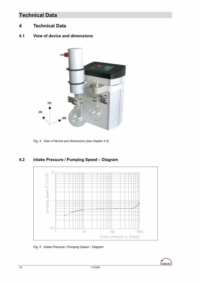
4.2 Intake Pressure / Pumping Speed – Diagram
Fig. 5 Intake Pressure / Pumping Speed – Diagram
14 113184

Technical Data
4.3 Device data
Parameter Data Unit Pumping speed 50/60 Hz at speed of 1500 rpm (DIN 28432) 1.1 / 1.2 m3 / h
Ultimate pressure at speed of 1500 rpm < 2 mbar Max. inlet pressure 1 bar Max. outlet pressure 1 bar Intake and pressure ports Hose nozzle for vacuum hose NW 8 - Ambient temperature + 10 bis + 40 °C Max. Operating gas temperature + 60 °C Bearing maintenance-free - Reference surface sound pressure level DIN 45635 part 13 < 44 dB (A)
Voltage / Frequency 90 – 240, 50/60 (generally with motor protection switch, switch and cable)
V - AC, Hz
Power 0.83 kW Operating mode S 1 - Type of protection DIN EN 60529 IP 20 - EC Direct current motor 24 V Class of insulation (Motor) DIN EN 600034-1 F (160°C) - Micro fuse (slow-acting) T 1 A Dimensions (W/D/H) 250 / 260 / 435 mm Weight 9.0 kg Order number for LVS : - without mains connection cable 113184 -
Order numbers for : - Mains connection cable CEE 825885 - Mains connection cable UK 825878 - Mains connection cable CH 825877 - Mains connection cable US 825903
-
Vacuum Controller : 3 conductor interface -
10 Hz 12 Bit
+ 5 stabilized V
Sensor interface : • Scan frequency • Resolution ADC • Power supply • Sensor signal 0.5 to 4.5 (optionally also 0..5 V or 4..20 mA possible) V Display digital; red, 9 mm high digits in mbar, torr or psi - Switching accuracy / control accuracy ±1 digit
digital - 0; 24 V
12 W
Switching outputs : • Voltage level • Control power, single • Control power, total 24 W
2 x
Switching outputs used : • Ventilation valve • Water valve x
-
analog - 0 to 10 V
Output analog: • Voltage level • Resolution DAC 8 Bit Communication interfaces RS 232 , RS 485 (optional) - Power consumption Controller in normal operation max. 20 (depends upon the control power) W
Fuse (internal controller) 5 A Sensor : integrated Sensor type ceramic sensor - Measuring range 1 - 1100 mbar Measuring uncertainty ±2; FS mbar Power pack : internal Operating voltage 90 .. 264 V AC Operating frequency 50 / 60 Hz Output voltage 24 V DC Output current 4 A Output power 100 W Connections : IN/OUT : RS 232 SUB-D plug 9-pole - OUT: Water valve Binder socket 4-pole, 24 V DC - Connection : Inert gas integrated, Hose nozzle DN 4 - OUT: mobile operating pad Binder socket 4-pole -
113184 15

Assembly and Installation
5 Assembly and Installation
5.1 Unpacking Carefully unpack the laboratory-vacuum-system. Check the system for: • Transport damage,
• Conformity with the specifications of the supply contract (type, electrical supply data), • Completeness of the delivery. Please inform Ilmvac GmbH without delay if there are discrepancies between the delivery and the contractually agreed scope of delivery, or if damage is detected.
– Please take note of the general terms of business of ILMVAC GmbH.
In case of a claim under warranty, the device must be returned in packaging that issuitable for protecting it during transport.
5.2 Installation and Connection • Set the laboratory-vacuum-system on a flat and horizontal surface. • Remove the protective caps on the connections.
• Connect the suction connector of the LVS to your apparatus with vacuum hose DN8. • Connect the cooling water tube to the emission condenser. • The cooling water return flow must be unpressurized. • Connect the air exhaust to the central air exhaust system.
• Connect the laboratory-vacuum-system to the power supply. • Check that the connections are properly seated.
5.2.1 General instructions Observe the basic safety instructions when using the LVS. The pressure device regulation 97/23/EC must be observed if devices with an overpressure of 0.5 bar or more are connected. The pressures at the suction and pressure sides of the diaphragm pump at the time it is switched on must correspond to the specifications of DIN 28432. In order to avoid pumping speed losses, all the vacuum connecting hoses used should have a large nominal diameter and should be laid out so that the lengths are as short as possible. Avoid rigid connections. They must be assembled carefully in order to achieve a low leak ra-te. We recommend fitting non-return valves (order no. 720327) for applications with several consumers. The upstream separator on the suction-side serves to protect the diaphragm pump and the vacuum sensor from condensates and mechanical contamination. It must be used for an ap-plication. The level in the separator must be monitored and the separator emptied regularly. The currently valid regulations must be observed when disposing of waste. The separator on the suction-side can only be removed and emptied after the system has been vented.
16 113184
Assembly and Installation The emission condenser enables a 100 per cent recovery of the solvents led through the vacuum pump. Cooling takes place via the DN 8 hose nipples. Ensure that the outflow is clear. The safety valve is located at the gas inlet. The rubber valve seal must be checked for cracks at regular intervals and exchanged when necessary. The exhaust connection must always be clear, and the exhaust can be led off through a DN 8 hose into a suitable evacua-tion duct. There is common solvent reclamation for all the connected systems. Mixing media must not lead to a hazard for persons, the environment of for the equipment. The vacuum ducts must always be laid sloping downwards so that condensates can flow into the relevant separators. In case of soiling by solid matter, the pump heads must be opened and the entire interior space, including valves and diaphragm, cleaned mechanically (see chapter 7.2.1).
5.3 Storage The pumps are to be stored in a low-dust, interior room within the temperature range from + 5 to + 40 °C and at a relative air humidity < 90%. Leave the protective elements on the suction and pressure ports. Another equally good pro-tection may be used.
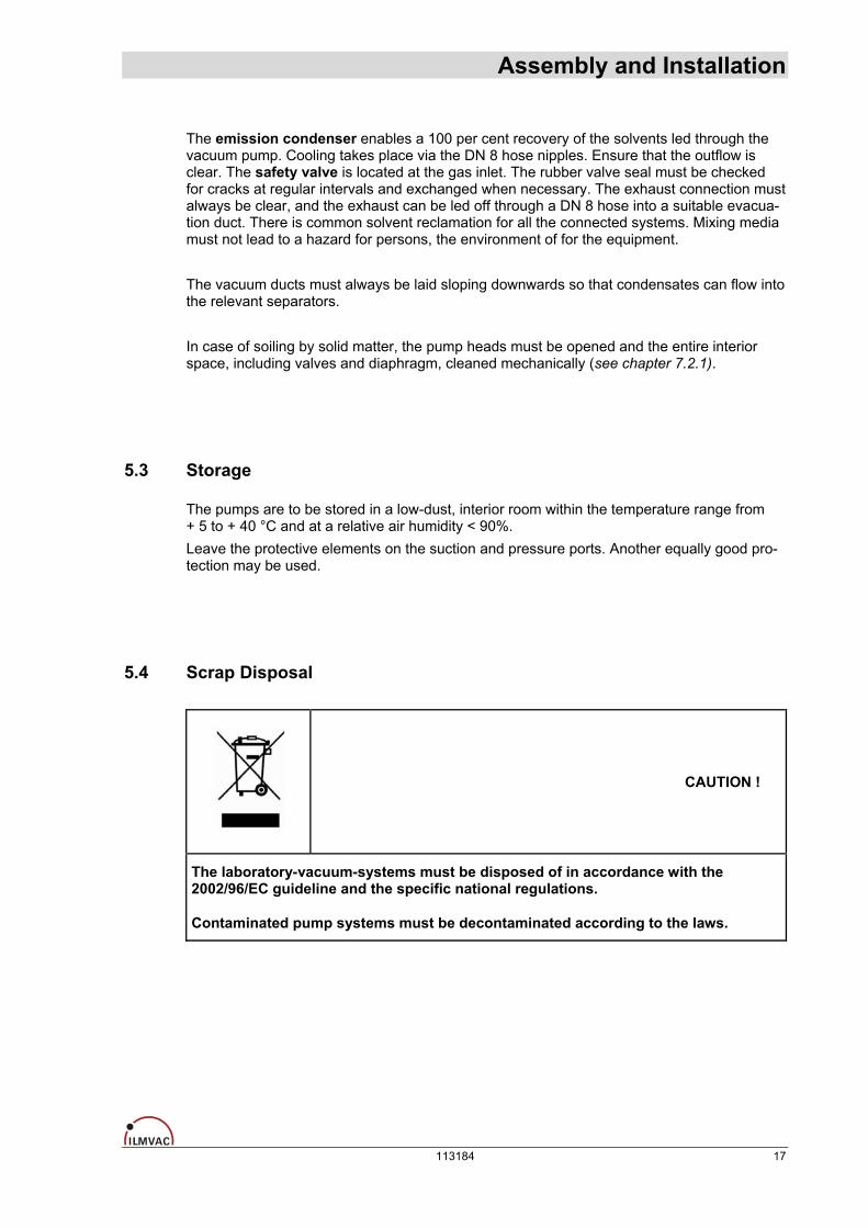
5.4 Scrap Disposal
CAUTION !
The laboratory-vacuum-systems must be disposed of in accordance with the 2002/96/EC guideline and the specific national regulations.
Contaminated pump systems must be decontaminated according to the laws.
113184 17
Operation
6 Operation
6.1 Control panel
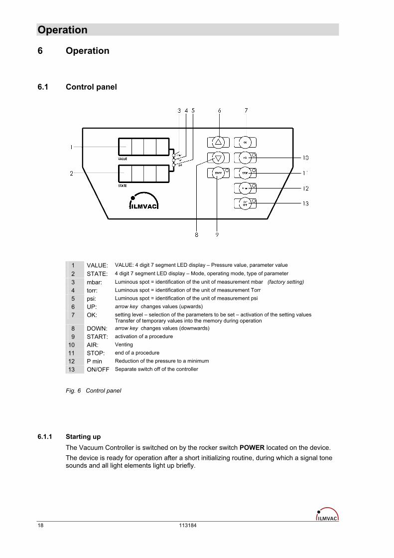
1 VALUE: VALUE: 4 digit 7 segment LED display – Pressure value, parameter value
2 STATE: 4 digit 7 segment LED display – Mode, operating mode, type of parameter
3 mbar: Luminous spot = identification of the unit of measurement mbar (factory setting) 4 torr: Luminous spot = identification of the unit of measurement Torr 5 psi: Luminous spot = identification of the unit of measurement psi
6 UP: arrow key changes values (upwards)
7 OK: setting level – selection of the parameters to be set – activation of the setting values Transfer of temporary values into the memory during operation
8 DOWN: arrow key changes values (downwards)
9 START: activation of a procedure
10 AIR: Venting
11 STOP: end of a procedure 12 P min Reduction of the pressure to a minimum
13 ON/OFF Separate switch off of the controller Fig. 6 Control panel
6.1.1 Starting up The Vacuum Controller is switched on by the rocker switch POWER located on the device. The device is ready for operation after a short initializing routine, during which a signal tone sounds and all light elements light up briefly.
18 113184

Operation
6.2 Operating modes of the Controller Setting to different operating modes (see chapter 6.4.2)
Manual mode Mode 1
Lowering the working pressure until the set pressure has been attained and held constant. After switching on the power supply to the vacuum pump and controller, and selecting mode 1, the process is started by pressing the start button. The pressure is reduced to the set pressure value PS (mbar) 1), see Setting control parameters. In this way, the pressure is held constant by two defined threshold values (set value, hysteresis). This operating mode exemplifies the classical 2-point control. This control procedure is repeated until the operator terminates operation (STOP key). The receptacle may be ventilated by pressing the AIR key. The set value may also be changed during operation in manual mode by means of (↑,↓). This set value is not stored, so the set value present at program start is retained. (see chapter 6.2.5) "ecoflex" pump models work directly at the set pressure value.
Manual mode with settable pressure reduction Mode 2
As in operating mode 1, but with an additional function for adapting the evacuation process to processes in which the boiling point shifts (reduction of the concentration of the volatile com-ponent). After attaining the set pressure value PS, there is a further pressure reduction corresponding to the set pressure value PL (1...1000 mbar) and a time tL (1...240 min) 2) which has to be defined previ-ously. The maximum rate of change of pressure is limited to 1 mbar/s.
Mode 5 Automatic operation
Lowering the working pressure until a boiling point is found automatically (also with mixtures).In the automatic operating modes, the controller continuously checks the course of the pumping out curve (pressure change per unit time). It interprets significant deviations in the slope as the start of vapour formation and defines this pressure point as a set value. That is, the controller treats the value found in this way from now on in the same way as the set value in the previous modes. The sensitivity of the controller can be set with parameter PA (a higher PA value for volatile substances and a lower PA value for non-volatile substances, (see Setting control parameters)). After finding the pressure point, the controller carries on working in mode 1. In the case of certain solvent mixtures or deeply cooled condensates, the optimal boiling point is not always found. In such cases, the distillation process may be further optimised by repeating with chan-ged PA values. Maximum distillation speed can be achieved in this way, taking into account the cooler capacity and the stability of the vaporization process (no frothing of the distillate).
Automatic operation with settable pressure reduction Mode 6
As operating mode 5, and after the boiling point has been found, in order to get a further low-ering of the working pressure corresponding to the set pressure value PL (mbar) and tL (min) 2) .
CAUTION !
The vacuum controller is released for the application of modes 1, 2, 5 and 6. The mode required is selected according to the work task and the connected periph-eral equipment.
1) Corresponding to the set unit of measurement: mbar, Torr, psi 2) tL is displayed on the control panel in minutes, and in the "ILMVAC-Control" program in seconds.
113184 19

Operation 6.2.1 Selection, display of operating modes
After switching on, the desired operating mode can be set with the cursor keys ↑ UP and ↓ DOWN. The current operating mode appears in the first position of the display and is acti-vated with the START key (a "-" appears in the second position of the display). The STOP key terminates the operating mode ("-" disappears) and the control is thus disabled. The current control parameters can be brought into the display while the program is running without interrupting the control sequence by pressing the START key for 3 seconds. The code letter of the currently selected parameter appears in the STATE display field and its associated value in the VALUE display field.
6.2.2 Setting / changing the control parameters at the controller The configuration menu is used to set the control parameters. It may only be entered when the control is inactive (control interrupted with the STOP key). Press the OK button for three seconds. The mode code in the VALUE display field changes to P. Select the setting parameter with the ↑ UP and ↓ DOWN buttons (see table below). Only those parameters which have to be set for the selected mode are displayed. Key to the code letters: P Pressure settings in (<de> = set pressure unit mbar, torr or psi) PS <de> Set value Modes 1, 2 PL <de> Amount of pressure reduction (Low pressure) Modes 2, 6 PA <de>/min threshold value for detecting the boiling point automatic mode Modes 5, 6 t Time setting tL min Time for the pressure reduction (Low pressure) Modes 2, 6 tH min After-running time for the cooling water (H2O) Modes 1, 2, 5, 6 C Pressure sensor calibration CH <de> at normal pressure 3) (High) CL <de> at low pressure (Low) (at lowest possible pressure, e.g. 10 mbar) F Frequency reduction in %, starting from the maximum operating frequency FA % For determining the boiling point smoothly. Manufacturer recommendation
= 32 %. Depending on the solvent, this value may have to be determined and corrected iteratively.
Modes 5, 6
3) daily air pressure / barometric pressure
After selecting the parameter, confirm it with OK. This display changes to "E". Set the desired value with the↑ UP and↓ DOWN keys, confirm with OK, and repeat with the other required parameters if necessary. Press the STOP key to leave the setting menu. The set values are stored after the setting menu has been left.
20 113184
Operation 6.2.3 Setting the selected control parameters
During operation, the current pressure value (mbar) is shown in the VALUE display field, there is a "P" in the STATE display field.
6.2.4 Querying the set values The set values can be displayed during operation by repeatedly pressing the START button.
6.2.5 Changing the pressure during operation The set value can be changed at any time by pressing the UP and DOWN keys. The display changes from "P" to "S" during the setting. This set value is temporarily active. After pressing the "STOP" button, the originally stored set value becomes active once more. If this iteratively determined set value is to be permanently transferred into the memory, this may be done by pressing the OK key once. The diaphragm pump is switched to continuous operation by pressing the Pmin button, irre-spective of the set parameters.
6.2.6 Set minimum pressure The diaphragm pump is switched to continuous operation by pressing the Pmin button, irre-spective of the set parameters. The attainable minimum pressure stabilizes after an ade-quate waiting time.
6.2.7 Venting the system The system may be vented by pressing the AIR key at any time. However, it must be noted that this also ends the search run in automatic mode. Venting is intermittent while the controller is active. That is venting takes place only as long as AIR is kept pressed. When the controller is inactive, pressing AIR completely vents the system. Whether or not automatic venting takes place after finishing operation can also be set with the "ILMVAC-Control" program. (Dialog box element: „air valve at STOP“) OFF means the automatic venting switched OFF. ON means the automatic venting switched ON.
CAUTION !
If check valves have been fitted in the vacuum system, its venting may be restricted from time to time!
113184 21
Operation 6.2.8 Setting the after-running time for the cooling water
The cooling water valve (optional) can be used to cut-off a cooling circuit after a time delay after pressing STOP. The after-running time tH can be set for all manual and all automatic modes (1, 2, 5, 6). The value tH = 0 is a special case. In this case, the cooling water valve remains open, even after STOP.
6.3 Calibration The calibration menu enables long-term changes in the pressure sensor to be compensated for. Calibration should take place every six months or whenever displayed pressures cease to be plausible. We recommend that the calibration be performed with a comparison measurement device. For this, the measured values: normal 3) and low pressure must be input. Calibration can be made on the control panel or somewhat more easily with the "ILMVAC-Control" PC program (see chapter 6.4).
6.3.1 Run via control panel # Switch the device on at the HS ("Hauptschalter" - main switch, rear side of device) # Press the OK key for 3 seconds # Select the calibration parameter CL (↑, ↓) # Press the OK key – “E” appears in display # Evacuate until ultimate pressure < 50 mbar # Set the pressure from the comparison measurement device with the cursor keys ↑ UP
and ↓ DOWN # Confirm correspondence with OK, this is followed by automatic venting to atmospheric
pressure. # Press the ↑ UP key – CH appears in the display (Calibrate, High) # Press the OK key – "E" appears in display # Set the daily air pressure with the cursor keys ↑ UP and ↓ DOWN # Press the OK key – "E" disappears # Press the STOP key to leave the setting level, setting is stored
CAUTION !
Instead of measuring the pressure with a comparison measurement device, the ulti-mate pressure of the pump used may also be input if this is known with sufficient accuracy (take note of evacuation time). Ensure that the set pressure is also present at the sensor.
3) daily air pressure / barometric pressure
22 113184
Operation
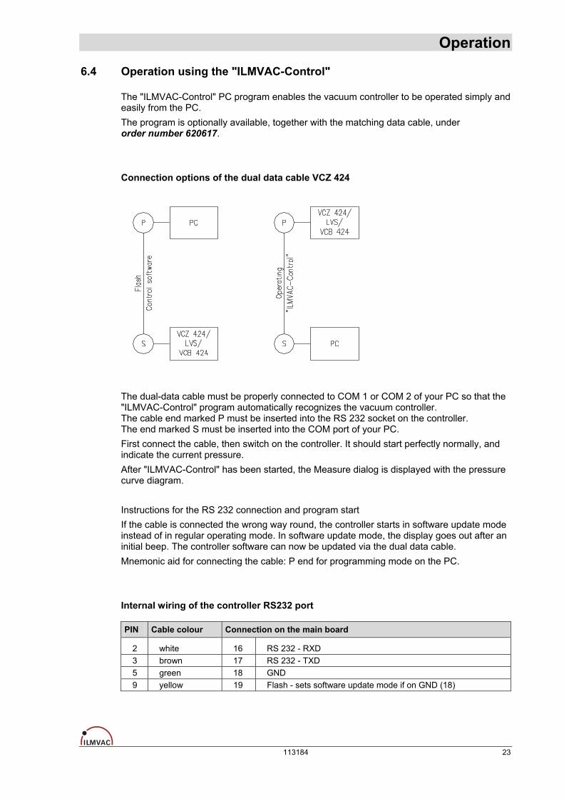
6.4 Operation using the "ILMVAC-Control" The "ILMVAC-Control" PC program enables the vacuum controller to be operated simply and easily from the PC. The program is optionally available, together with the matching data cable, under order number 620617. Connection options of the dual data cable VCZ 424
The dual-data cable must be properly connected to COM 1 or COM 2 of your PC so that the "ILMVAC-Control" program automatically recognizes the vacuum controller. The cable end marked P must be inserted into the RS 232 socket on the controller. The end marked S must be inserted into the COM port of your PC. First connect the cable, then switch on the controller. It should start perfectly normally, and indicate the current pressure. After "ILMVAC-Control" has been started, the Measure dialog is displayed with the pressure curve diagram. Instructions for the RS 232 connection and program start If the cable is connected the wrong way round, the controller starts in software update mode instead of in regular operating mode. In software update mode, the display goes out after an initial beep. The controller software can now be updated via the dual data cable. Mnemonic aid for connecting the cable: P end for programming mode on the PC. Internal wiring of the controller RS232 port
PIN Cable colour Connection on the main board
2 white 16 RS 232 - RXD 3 brown 17 RS 232 - TXD 5 green 18 GND 9 yellow 19 Flash - sets software update mode if on GND (18)
113184 23

Operation The vacuum controller can also be connected to COM 3 or higher. However, "ILMVAC-Control" can then no longer automatically recognize the device. The number of the COM port then has to be transferred as a parameter when the program starts. If your controller is connected to COM 3, you must input the following command in order to start "ILMVAC-Control".
The command can be input, for example in the Windows start menu via "Run". The quotation marks in the command are only required if there is a space in the file path. The following screen appears after the start:
The graph shows the pressure development after pressing the START button.
24 113184
Operation The time axis (time range) and pressure axis (pressure 0..n) can be scaled, and the sam-pling rate (saving interval) can be set with the dialog box elements below the diagram. Only those buttons relevant to the currently set mode are active. Break (F7) and Reset (F9) are not needed for the vacuum controller modes. • The buttons can be operated with the mouse, as on the controller (see chapter 6.1). • The UP and DOWN arrow buttons change the temporary set value in active MODE.
• The OK button sets the current pressure as the new set value in active MODE. • The START button starts the selected operating mode. • The STOP button ends an active operating mode.
The following menu items can be selected from the menu bar: • File
• Measure ! • Settings ! • Alarm ! • Calibrate !
• Factory settings !
6.4.1 Menu item: „File“ File
Save settings - Saving the Settings dialog settings in a file
Load settings - Loading the Settings dialog settings from a file
Print settings - Printing out an image of the Settings dialog on the standard printer
Save memory - Saving the pressure data in a file
Print curve - Printing out the current pressure curve on the standard printer
Password - Changing the basic setting of the controller is password-protected. Release is given by inputting the date as a hex number.
Example : 13.02.2005 = 130205 = 1FC9D (Required for activating the "Calibrate" and "Factory settings" menus and the direct input of pressure offset und pressure factor in the „Calibrate“ Dialog)
Info - Information about the program version
Exit <ESC> - Exit program
113184 25

Operation 6.4.2 Menu item: „Settings!“
CAUTION !
Settings not required for the selected operating mode are disabled and grayed out in the display. Appropriate error messages are displayed if the data ranges are ex-ceeded or if inputs are illogical.
26 113184
Operation
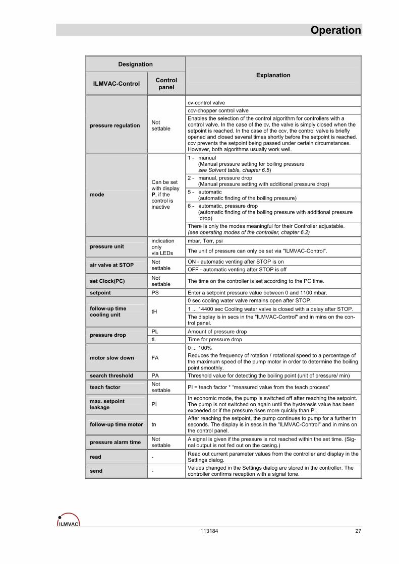
Designation
ILMVAC-Control Control panel
Explanation
cv-control valve ccv-chopper control valve
pressure regulation Not settable
Enables the selection of the control algorithm for controllers with a control valve. In the case of the cv, the valve is simply closed when the setpoint is reached. In the case of the ccv, the control valve is briefly opened and closed several times shortly before the setpoint is reached. ccv prevents the setpoint being passed under certain circumstances. However, both algorithms usually work well. 1 - manual (Manual pressure setting for boiling pressure see Solvent table, chapter 6.5) 2 - manual, pressure drop (Manual pressure setting with additional pressure drop) 5 - automatic (automatic finding of the boiling pressure) 6 - automatic, pressure drop (automatic finding of the boiling pressure with additional pressure drop)
mode
Can be set with display P, if the control is inactive
There is only the modes meaningful for their Controller adjustable. (see operating modes of the controller, chapter 6.2) mbar, Torr, psi
pressure unit indication only via LEDs The unit of pressure can only be set via "ILMVAC-Control".
ON - automatic venting after STOP is on air valve at STOP Not settable OFF - automatic venting after STOP is off
set Clock(PC) Not settable The time on the controller is set according to the PC time.
setpoint PS Enter a setpoint pressure value between 0 and 1100 mbar. 0 sec cooling water valve remains open after STOP. 1 ... 14400 sec Cooling water valve is closed with a delay after STOP. follow-up time
cooling unit tH The display is in secs in the "ILMVAC-Control" and in mins on the con-trol panel.
PL Amount of pressure drop pressure drop tL Time for pressure drop
motor slow down FA
0 ... 100% Reduces the frequency of rotation / rotational speed to a percentage of the maximum speed of the pump motor in order to determine the boiling point smoothly.
search threshold PA Threshold value for detecting the boiling point (unit of pressure/ min)
teach factor Not settable PI = teach factor * “measured value from the teach process“
max. setpoint leakage PI
In economic mode, the pump is switched off after reaching the setpoint. The pump is not switched on again until the hysteresis value has been exceeded or if the pressure rises more quickly than PI.
follow-up time motor tn After reaching the setpoint, the pump continues to pump for a further tn seconds. The display is in secs in the "ILMVAC-Control" and in mins on the control panel.
pressure alarm time Not settable
A signal is given if the pressure is not reached within the set time. (Sig-nal output is not fed out on the casing.)
read - Read out current parameter values from the controller and display in the Settings dialog.
send - Values changed in the Settings dialog are stored in the controller. The controller confirms reception with a signal tone.
113184 27

Operation 6.4.3 Menu item: „Alarm“
Timer function The time switch function is set via the PC level alarm. Two switching points are provided, each with a START and a STOP time. The START switching point behaves like an actuation of the START key, the STOP switch-ing point corresponds to the STOP key. All times are entered in hours and minutes. It is always used as the last module to be star-ted. The desired days of the week can be selected for each switching point. The switching point is deactivated is no day of the week has been selected. If the STOP time is earlier than the START time, then the system will not be stopped until the following day. Each time a switch-ing point is changed; the next START point is selected and activated together with its STOP point. This occurs both when the device is switched on and when the STOP point is reached.
28 113184
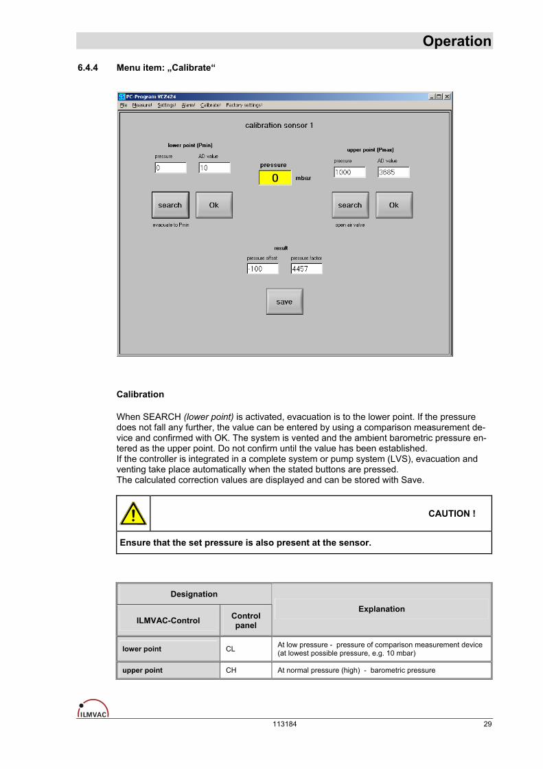
Operation 6.4.4 Menu item: „Calibrate“
Calibration When SEARCH (lower point) is activated, evacuation is to the lower point. If the pressure does not fall any further, the value can be entered by using a comparison measurement de-vice and confirmed with OK. The system is vented and the ambient barometric pressure en-tered as the upper point. Do not confirm until the value has been established. If the controller is integrated in a complete system or pump system (LVS), evacuation and venting take place automatically when the stated buttons are pressed. The calculated correction values are displayed and can be stored with Save.
CAUTION !
Ensure that the set pressure is also present at the sensor.
Designation
ILMVAC-Control Control panel
Explanation
lower point CL At low pressure - pressure of comparison measurement device (at lowest possible pressure, e.g. 10 mbar)
upper point CH At normal pressure (high) - barometric pressure
113184 29
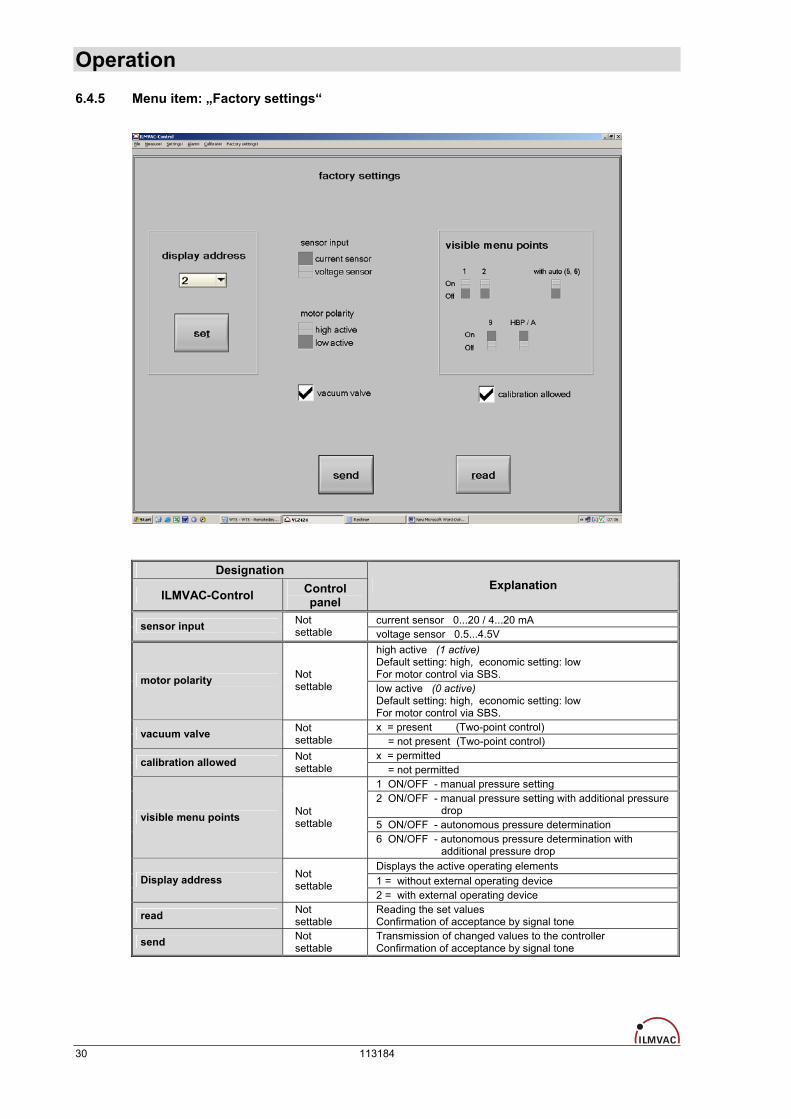
Operation 6.4.5 Menu item: „Factory settings“
Designation
ILMVAC-Control Control panel
Explanation
current sensor 0...20 / 4...20 mA sensor input Not settable voltage sensor 0.5...4.5V
high active (1 active) Default setting: high, economic setting: low For motor control via SBS. motor polarity Not
settable low active (0 active) Default setting: high, economic setting: low For motor control via SBS. x = present (Two-point control) vacuum valve Not
settable = not present (Two-point control) x = permitted calibration allowed Not
settable = not permitted 1 ON/OFF - manual pressure setting 2 ON/OFF - manual pressure setting with additional pressure drop 5 ON/OFF - autonomous pressure determination
visible menu points Not settable
6 ON/OFF - autonomous pressure determination with additional pressure drop Displays the active operating elements 1 = without external operating device Display address Not
settable 2 = with external operating device
read Not settable
Reading the set values Confirmation of acceptance by signal tone
send Not settable
Transmission of changed values to the controller Confirmation of acceptance by signal tone
30 113184

Operation
CAUTION !
These settings are adapted by the manufacturer to match the supplied configuration. The user can change the settings after inputting the password (“File” menu item).
6.4.6 Operation via RS 485 (according to NAMUR NE 28) Optionally the vacuum controller can be expanded to have an RS 485 port.
CAUTION !
The millibar is to be used as a unit of pressure.
The interface parameters must be set to: RS 485, 9600 baud, 7 databits, no parity and 1 stopbit, no handshake
All entries are concluded with CR/LF. The answer is the required value concluded by CR/LF or nothing with inputs. Folowing commands are available: START m Start in mode m (1..10) (motor on, vacuum valve open, ventilation closed)
STOP End Mode (motor on, vacuum valve closed, ventilation remains closed)
OUT_SP_0 x Specified setpoint, permitted values 0..1000 IN_SP_0 Read current setpoint (4 digits with leading zeros)
OUT_PAR_0 0/1 Switch venting valve 0 = OFF, 1 = ON IN_PAR_0 Reread the state of the vent valve 0/1
IN_PV_0 Read current pressure (4 digits with leading zeros)
STATUS Current status: 0 = inactive, 1..10 active Mode or negative (error will be reset)
Following errors are defined: - 1 OVL Input buffer overflow (40 digits) - 2 CMD Command unknown - 3 PAR Parameter invalid - 4 COM Communication error (e.g. time-out)
Examples:
Transmission : Reply : STATUS [CR/LF] +1 [CR/LF] OUT_SP_0 100 [CR/LF] none OUT_SP_0 2000 [CR/LF] none, error –3 IN_PV_0 [CR/LF] 0435 [CR/LF]
113184 31

Operation
6.5 Table of solvents
Solvent Formula Vacuum (mbar) for boiling point at 40 °C
Acetone C3H6O 556 n-amyl alcohol, n-pentanol C5H12O 11 Benzole C6H6 236 n-butanol C4H10 25 tert-butyl alcohol, 2-methyl-2-propanol C4H10O 130 Tetrachloromethane CCl4 271 Chlorobenzene C6H5Cl 36 Chloroform CHCl3 474 Cyclohexane C6H12 235 Diethyl ether C4H10O no vacuum 1, 2-dichloroethane C2H4Cl2 210 1, 2-dichlorethylene (cis) C2H2Cl2 479 1, 2-dichlorethylene (trans) C2H2Cl2 751 Diisopropyl ether C6H14O 375 Dioxan C4H8O2 107 DMF C3H7NO 11 Ethanol C2H6O 175 Ethyl acetate C4H8O2 240 Heptane C7H16 120 Hexane C6H14 335 Isopropyl alcohol C3H8O 137 Isoamyl alcohol, 3-methyl-1-butanol C5H12O 14 Ethyl methyl ketone C4H8O 243 Methanol CH4O 337 Methylene dichloride, dichloromethane CH2Cl2 no vacuum Pentane C5H12 no vacuum n-propyl alcohol C3H8O 67 Pentachloroethane C2HCl5 13 1, 1, 2, 2-tetrachloroethane C2H2Cl4 35 1, 1, 1-trichloroethane C2H3Cl3 300 Tetrachloroethylene C2Cl4 53 THF C4H8O 357 Toluol C7H8 77 Trichloroethylene C2HCl3 183 Water H2O 72 Xylol C8H10 25
Vacuum in Torr/mmHg = X mbar x 0.71
32 113184

Maintenance and Servicing
7 Maintenance and Servicing
7.1 General Requirements Repairs of the Laboratory-Vacuum-Systems may only be performed by the manufacturer or authorized workshops. The prerequisites are a complete and factually correct damage report, and a clean and, if necessary, a decontaminate device. The operator may perform maintenance work to the extent indicated below:
7.2 Maintenance Performed by the User
WARNING !
Only perform the work that is described here, and that which is permitted to be done by the user. All other maintenance and service work may only be performed by the manufacturer or a dealer authorized by him. Beware of the pump parts being possibly contaminated by hazardous substances. Wear protective clothing if there is contamination.
7.2.1 Maintenance of the diaphragm pump • Check the pump daily for unusual running noises and heat building up on the surface of the pump. • We recommend changing the diaphragm after 10,000 operating hours. The user may specify that
the exchange be made earlier, depending upon the application process.
• Check the electrical and vacuum connections daily. –
WARNING !
Before opening the pump unplug it from the mains.
Scope of permissible work: • Inspect the pump chambers, diaphragms and valves, • Deposits in the inside of the pump must be cleaned out, • Change the diaphragms, valves and seals.
Tools required: The tool kit, order No. 402107 consists of: • 826801-4 Cross-head screwdriver, size 2, • 826801-2 Open spanner, size SW 14, • 826801-9 Open spanner, size SW 7.
113184 33

Maintenance and Servicing 7.2.1.1 Disassembly
• Disconnect the power supply and ensure that it cannot be switched on again. • Open the cover of the casing at the following operational sequence:
1.
Release the suction and pressure side connections to the pump. Remove the holding bracket (A) with the separator.
2. Remove the elbow unions (B).
3. Loosen at the device lower surface the four cross-head M4 (C).
4. Pull the hood off upwards, and unplug the plug from the display panel.
Fig. 7 Disassembly - lower surface casing
• Open the screw clamps of the hose link on the pump bodies with the SW 14 open spanner. • Remove 2 x 4 screws (1) from each connecting head (2) with a cross-head screwdriver, size 2. • Lift off the connecting head (2) and the pump head (5). The diaphragm is now freely exposed.
• Loosen the defective diaphragm (6) by turning it anticlockwise. • Valves (4) (see fig. 9) and o-rings (3) are located between the connecting and the pump head.
When dismounting both heads these parts are accessible. • Clean the valves (4) (see fig. 9), o-rings (3) and diaphragm (6) with a soft cloth and acetone and re-
place defective items if necessary.
Fig. 8 Disassembly, assembly
WARNING !
Renew defective parts, if necessary ! Wear protective gloves! Parts must be renewed at the intervals stated in this Operating Manual or as speci-fied by the user internally. Do not clean with compressed air.
34 113184
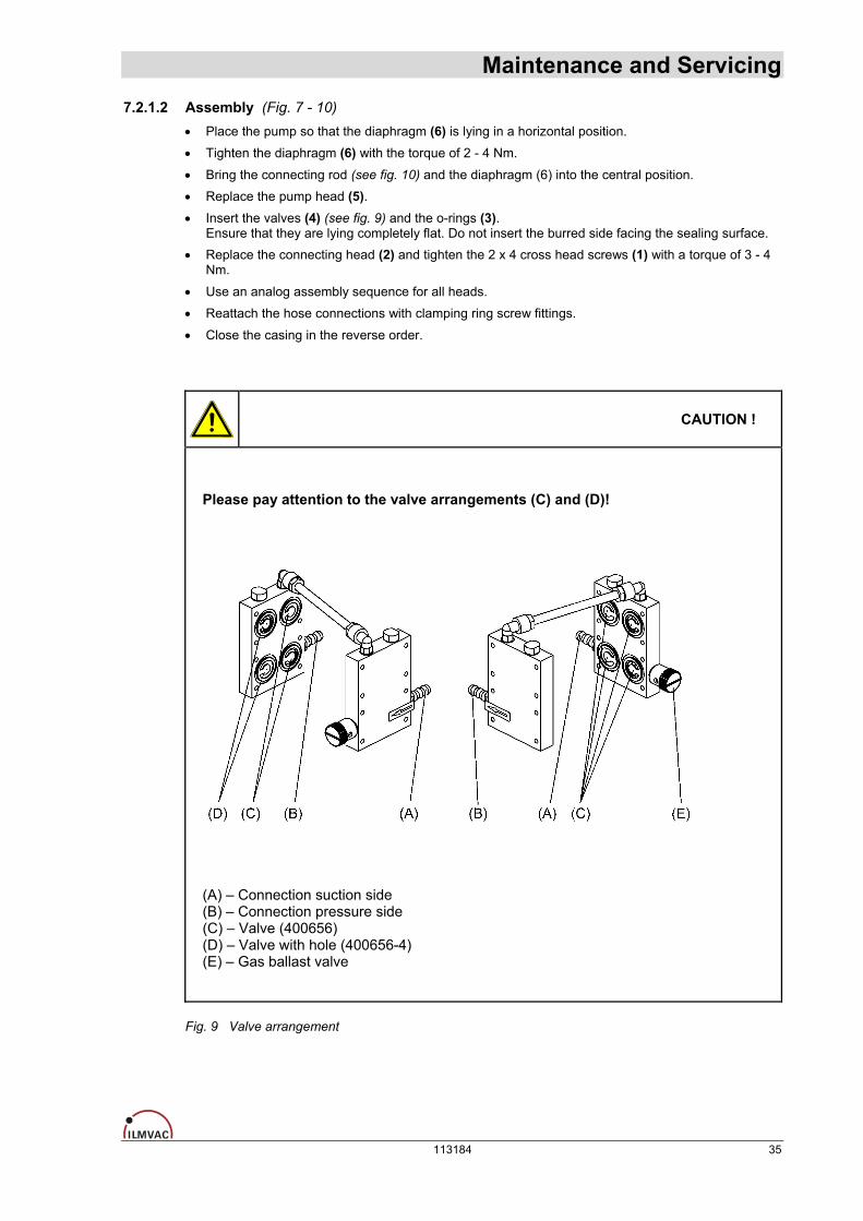
Maintenance and Servicing 7.2.1.2 Assembly (Fig. 7 - 10)
• Place the pump so that the diaphragm (6) is lying in a horizontal position. • Tighten the diaphragm (6) with the torque of 2 - 4 Nm.
• Bring the connecting rod (see fig. 10) and the diaphragm (6) into the central position. • Replace the pump head (5). • Insert the valves (4) (see fig. 9) and the o-rings (3).
Ensure that they are lying completely flat. Do not insert the burred side facing the sealing surface. • Replace the connecting head (2) and tighten the 2 x 4 cross head screws (1) with a torque of 3 - 4
Nm.
• Use an analog assembly sequence for all heads. • Reattach the hose connections with clamping ring screw fittings.
• Close the casing in the reverse order.
CAUTION !
Please pay attention to the valve arrangements (C) and (D)!
(A) – Connection suction side (B) – Connection pressure side (C) – Valve (400656) (D) – Valve with hole (400656-4) (E) – Gas ballast valve
Fig. 9 Valve arrangement
113184 35
Maintenance and Servicing 7.2.1.3 Test
• Connect the system to the electrical supply. • Connect a vacuum measuring device to the suction connector and measure the ultimate pressure.
If the device is working properly, then the figure stated in the technical data must be attained within a maximum of one minute.
• The pump must not make any abnormal noises. • Moving parts must not touch each other.
7.2.2 Maintenance of the vacuum controller The controller is maintenance-free. In case of damage, return the device to the manufacturer or to an authorized workshop.
7.2.3 Maintenance of other components • Empty the glass drip pan in a timely manner, observe all disposal specifications as applicable to
hazardous substances.
• Screw connections must be checked for tightness and tightened when necessary. • Check vacuum hoses for leaks and, if necessary, replace them. • Check that the glass vessels is undamaged and if necessary replace.
• Check rubber gasket of the safety valve at the emission condenser and, if necessary, replace it.
7.3 Maintenance by the Manufacturer Repairs and maintenance going beyond the extent of the work described in chapter 7.2 or reconditioning or modification may only be performed by the manufacturer or authorized workshops.
WARNING !
The user shall be liable for the consequences of an incorrect damage report or a contaminated pump. The statements in the damage report are legally binding.
7.4 Damage Report You find the form of the damage report to the Download on our web page http://www.ilmvac.de and/or. http://www.ilmvac.com in the menu "service" and "Downloads". If you should not have an entrance to the Internet, you can request the form also gladly with us, company Ilmvac GmbH.
WARNING !
Incomplete or incorrectly completed damage reports may endanger the service per-sonnel! Provide full information about contamination, and clean the pump thoroughly before handing it over to third parties.
36 113184
Troubleshooting
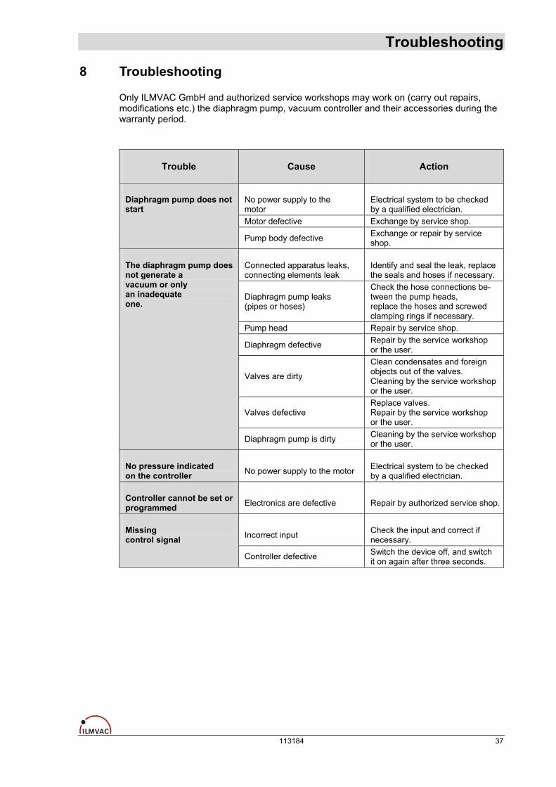
8 Troubleshooting Only ILMVAC GmbH and authorized service workshops may work on (carry out repairs, modifications etc.) the diaphragm pump, vacuum controller and their accessories during the warranty period.
Trouble Cause Action
No power supply to the motor
Electrical system to be checked by a qualified electrician.
Motor defective Exchange by service shop.
Diaphragm pump does not start
Pump body defective Exchange or repair by service shop.
Connected apparatus leaks, connecting elements leak
Identify and seal the leak, replace the seals and hoses if necessary.
Diaphragm pump leaks (pipes or hoses)
Check the hose connections be-tween the pump heads, replace the hoses and screwed clamping rings if necessary.
Pump head Repair by service shop.
Diaphragm defective Repair by the service workshop or the user.
Valves are dirty
Clean condensates and foreign objects out of the valves. Cleaning by the service workshopor the user.
Valves defective Replace valves. Repair by the service workshop or the user.
The diaphragm pump does not generate a vacuum or only an inadequate one.
Diaphragm pump is dirty Cleaning by the service workshopor the user.
No pressure indicated on the controller No power supply to the motor Electrical system to be checked
by a qualified electrician.
Controller cannot be set or programmed Electronics are defective Repair by authorized service shop.
Incorrect input Check the input and correct if necessary.
Missing control signal
Controller defective Switch the device off, and switch it on again after three seconds.
113184 37
Spare Parts Overview
9 Spare Parts Overview The spare parts list contains all the spare parts and all the information necessary for order-ing. When ordering, please quote the description, quantity, serial number and order number!
CAUTION !
Ilmvac is not liable for any damage caused by the installation of any parts not sup-plied by the manufacturer.
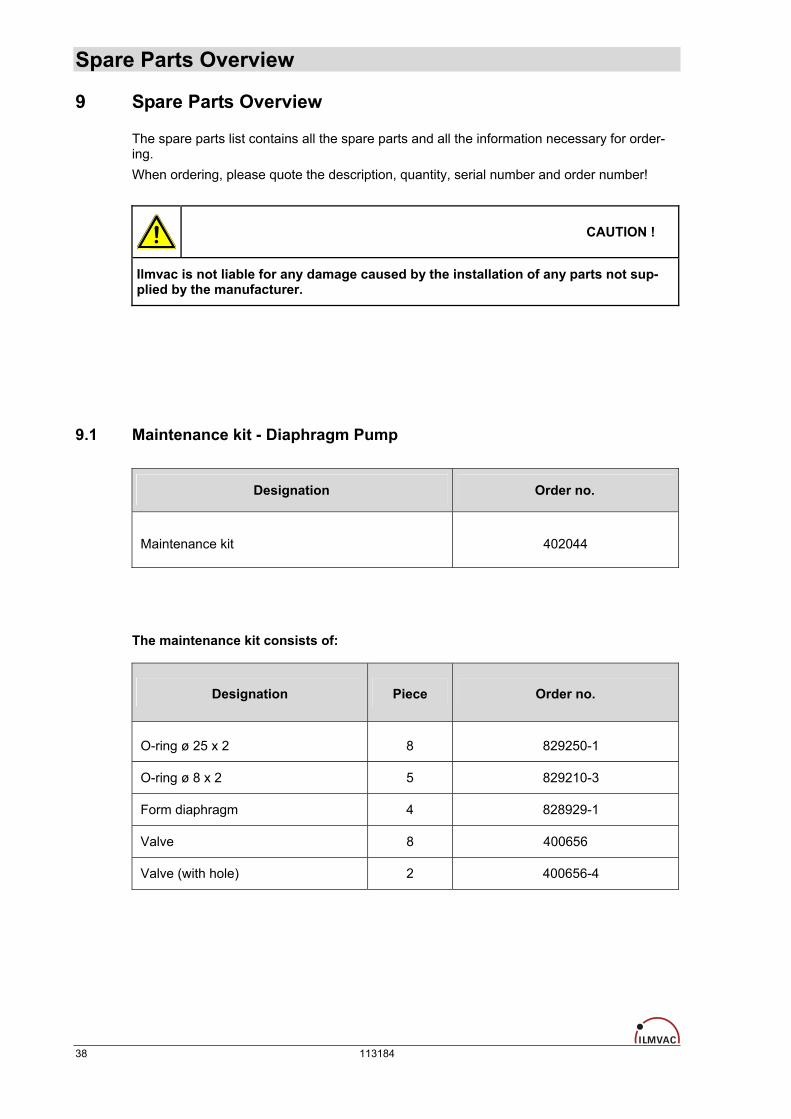
9.1 Maintenance kit - Diaphragm Pump
Designation Order no.
Maintenance kit 402044
The maintenance kit consists of:
Designation Piece Order no.
O-ring ø 25 x 2 8 829250-1
O-ring ø 8 x 2 5 829210-3
Form diaphragm 4 828929-1
Valve 8 400656
Valve (with hole) 2 400656-4
38 113184
Spare Parts Overview
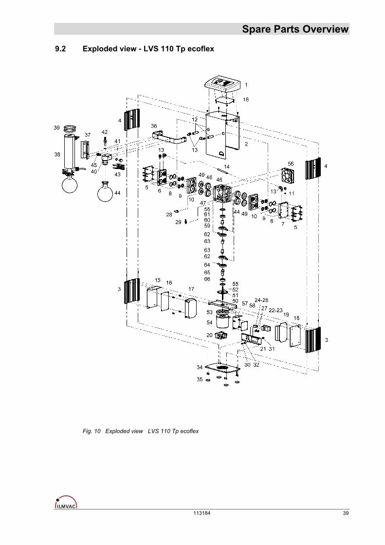
9.2 Exploded view - LVS 110 Tp ecoflex
Fig. 10 Exploded view LVS 110 Tp ecoflex
113184 39

Spare Parts Overview 9.2.1 Spare parts list - LVS 110 Tp ecoflex
Item no. Designation Piece Order no.
1 Casing cover 1 112556 2 Casing 1 113518 3 Alu-Profile 155 2 400950 4 Alu-Profile 128 2 400950-01 5 Pressure plate 4 400935 6 Connection head - suction side 1 400924 7 Connection head - pressure side 1 400924-01 8 O-ring Ø 25 x 2 8 829250-1
Valve 6 400656 9
Valve with hole 2 400656-4 10 Pump head 4 400898-02 11 O-ring Ø 8 x 2 2 829210-3 12 Extension PP, G1/8“ – G1/8“ 2 113527 13 Threaded elbow joint PVDF, 8 – 1/8“ 4 829936-1 14 Vacuum hose PTFE, 8 / 6 x 1 mm 1 m 828331 15 Adapter plate (for power pack) 1 400949-01 16 Insulating plate (for power pack) 1 113526 17 Power pack 120 W (PSA 120) 1 827397 18 Adapter plate (for printed circuit board) 1 400949-02 19 Controller VCZ 424 without casing 1 827398-02 20 Sensor for controller 1 620052-10 21 Switch panel 1 400947-01 22 Plug for non-heating apparatus - combination 1 825274 23 Fine fuse T 6.3 A 1 825372 24 9 pole connector Sub-D 1 825275-5 25 Pin set (for 9 pole connector Sub-D) 1 825275-1 26 Dust caps (for 9 pole connector Sub-D) 1 825275-2 27 Sub miniature round plug - flange box 4 pole 3 825277-1 28 Thermal switch 1 825158 29 Voltage regulator 1 826258 30 Screw-in socket 1 828791 31 Screw-in socket, modified 1 160837 32 Intermediate piece 160529 33 Silicone hose 0.3 m 828359 34 Foot plate 1 400937 35 Casing foot 4 829112 36 Holding bracket (for cooler) 1 113515 37 Cooler holder 1 113516 38 Emission condenser insulated KD 500/5 complete 1 700183-09 39 Retaining strap 70 – 75 mm 2 824130 40 Fixing piece (for separator) 1 113517 41 O-ring Ø 12 x 2 2 829217-3 42 Hose nozzle PP, DN 8 – G ¼” with lug 1 710798-06 43 Ball and socket clamp – KS 35 1 828845 44 Round-bottomed flask 500 ml – KS 35 1 828839 45 Straight threaded joint PVDF 8 – 1/8” 1 829919
1
40 113184

Spare Parts Overview
Item no. Designation Piece Order no.
- *) Basic pump MPC 104 Tp on intermediate plate (consisting of position: 46 - 66) 1 400918-04
46 Pump casing 1 400913 47 Rubber element 4 400916 48 Cylinder 4 400914 49 Form diaphragm 4 828929-1 50 Intermediate plate 1 400948 51 Insulating washer 2 400893-04 52 Shaft 1 400915-04 53 Space ring (for motor) 1 400923 54 Direct current motor 24 VDC, 83 1 826393-1 55 O-ring Ø 32 x 3 2 829258 56 Fan 1 829820-1 57 Adapter plate (for printed circuit board) 1 400949-04 58 Printed circuit board 1 825685 - Drive 1 - complete (consisting of position: 59 – 61) 2 400919
59 Piston rod with ball bearing 1 400892-01 60 Eccentric 1 400915 61 Ball bearing 1 824963-1 - Drive 2 - complete (consisting of position: 62 – 63) 2 400919-01
62 Piston rod with ball bearing 1 400892-01 63 Eccentric 1 400915 - Drive 3 - complete (consisting of position: 64 - 66) 1 400919-03
64 Piston rod with ball bearing 1 400892-01 65 Eccentric 1 400915-03 66 Ball bearing 1 824963-1
*) The "basic pump" module (items 46 – 66) can only be supplied complete under order number 400918-04.
113184 41