operation manual for exactcontrol - grinding control€¦ · sbs exactcontrol operation and...
TRANSCRIPT
Operation Manual for ExactControl™with SB-5500 Control
LL-5600 Rev. 1.5

Limited Use License Agreement
CAREFULLY READ THE FOLLOWING TERMS AND CONDITIONS BEFORE OPENING THE PACKAGE CONTAINING THE PRODUCT AND THE COMPUTER SOFTWARE LICENSED HEREUNDER. CONNECTING POWER TO THE MICROPROCESSOR CONTROL UNIT INDICATES YOUR ACCEPTANCE OF THESE TERMS AND CONDITIONS. IF YOU DO NOT AGREE WITH THE TERMS AND CONDITIONS, PROMPTLY RETURN THE UNIT TO THE DEALER FROM WHOM YOU PURCHASED THE PRODUCT WITHIN FIFTEEN DAYS FROM DATE OF PURCHASE AND YOUR PURCHASE PRICE WILL BE REFUNDED BY THE DEALER. IF THE DEALER FAILS TO REFUND YOUR PURCHASE PRICE, CONTACT SCHMITT INDUSTRIES, INC. IMMEDIATELY AT THE ADDRESS FOLLOWING CONCERNING RETURN ARRANGEMENTS.
Schmitt Industries, Inc. provides the hardware and computer software program contained in the microprocessor control unit. Schmitt Industries, Inc. has a valuable proprietary interest in such software and related documentation ("Software), and licenses the use of the Software to you pursuant to the following terms and conditions. You assume responsibility for the selection of the product suited to achieve your intended results, and for the installation, use and results obtained.
License Terms And Conditions
a. You are granted a non-exclusive, perpetual license to use the Software solely on and in conjunction with the product. You agree that the Software title remains with Schmitt Industries, Inc. at all times.
b. You and your employees and agents agree to protect the confidentiality of the Software. You may not distribute, disclose, or otherwise make the Software available to any third party, except for a transferee who agrees to be bound by these license terms and conditions. In the event of termination or expiration of this license for any reason whatsoever, the obligation of confidentiality shall survive.
c. You may not disassemble, decode, translate, copy, reproduce, or modify the Software, except only that a copy may be made for archival or back-up purposes as necessary for use with the product.
d. You agree to maintain all proprietary notices and marks on the Software.
e. You may transfer this license if also transferring the product, provided the transferee agrees to comply with all terms and conditions of this license. Upon such transfer, your license will terminate and you agree to destroy all copies of the Software in your possession.
A Product Line of Schmitt Industries, Inc.

SBS ExactControl
Operation and Specification Manual For the
SBS ExactControl Card
Covering Operation of SB-5560
with Model 5500/5575 series Control Unit
LL-5600
manual revision No. 1.5 Covers operation with product firmware rev. 0.25
© 2017 Schmitt Industries, Inc.
In partnership with: Dr. Zinngrebe GmbH
Corporate Offices 2765 NW Nicolai St.
Portland, OR 97210 USA
Tel: +1 503.227.7908
www.grindingcontrol.com
Schmitt EuropeGround Floor Unit 2
Leofric Court, Progress Way Binley Industrial Estate
Coventry, CV3 2NT, England
[email protected] [email protected] Tel: +44-(0)2476-651774
www.grindingcontrol.com

SBS ExactControl

SBS ExactControl
Benefits of SBS ExactControl™ System with SB-5500 Control
• Increases throughput by saving setup time
• Improves part quality by providing dress quality monitoring
• Gap Elimination - Increases throughput by reducing unproductive dress infeed.
• Crash Protection - Quick detection of extreme wheel contact to allow feed shutdown and prevent dangerous wheel crashes.
• Four-slot capability reduces costs by permitting both balancing and process monitoring on multiple machines.
• Longer life for grinding wheels, dressing wheels and spindle bearings
• Enhanced digital electronic design with increased operating life and reliability
• Easy to install and operate
• Works with existing SBS installations
• Profibus, Ethernet and Digital I/O communication
• International adaptability: voltage, frequency, communication, and display language
• Backed by world-class SBS customer service

SBS ExactControl
Table of Contents
System Purpose .................................................................................................................................. 9Operator Safety Summary .................................................................................................................. 9Process Control Overview .................................................................................................................10
Signal Inputs for Process Monitoring .................................................................................................................. 10
System Installation .............................................................................................................................11System Connections ........................................................................................................................................... 11Acoustic Sensor Location ................................................................................................................................... 13AE Sensor Types ................................................................................................................................................ 13Profibus, CNC ..................................................................................................................................................... 13Ethernet ............................................................................................................................................................... 13
Getting Started....................................................................................................................................14Basics for process monitoring ............................................................................................................................. 14User Interface – IVIS ........................................................................................................................................... 15
Process Operation Screen ....................................................................................................15Strategy Symbol: Process Status indicator ................................................................................................... 16
File Menu ............................................................................................................................................................ 17
Process Settings Screen ..............................................................................................................18Parameter job x ................................................................................................................................................. 18Job (1..16) – Select a Job number ..................................................................................................................... 18Name – Give a Name to the Job ........................................................................................................................ 18Instance x........................................................................................................................................................... 18Measurement signal – Select the signal to process ......................................................................................... 18Strategy – Select the method to use to process the signal ............................................................................... 18Switching output – Select the digital output to indicate the evaluation result .................................................. 19
Revision – Shows the card’s revisions ......................................................................................................... 19Device time – Shows the card’s time ........................................................................................................... 19Local time – Shows the computer’s time ...................................................................................................... 19Time difference – Shows local time minus device time ............................................................................... 19Digital IO Configuration – Set the functionality of the Digital IO port.......................................................... 19RPM Cycles/Revolution spindle 1 – Set the RPM sensor pulses per revolution ....................................... 20Spindle 1 Resolution [RPM Range] – Set the appropriate RPM resolution RPM scale............................. 20Name – Give a name to the card or its function ............................................................................................ 20
Measurement Signal Parameters.......................................................................................................20Measurement Signal Instance x: input x ........................................................................................................ 20
Inverted measurement – Select sense of signal direction .......................................................................... 20Measuring Method – Absolute or Relative ................................................................................................... 20Idling time – Time to acquire the start value ................................................................................................ 20Signal offset – Adjust for signal level shift ................................................................................................... 21Filter type – Select appropriate signal conditioning ..................................................................................... 21Filter time – Set the time constant for the selected Filter type ..................................................................... 21Display balancing – Optionally display balancing information .................................................................... 21Enable automatic scaling – Automatic scaling of Y axis ............................................................................ 21Scaling value – Maximum displayed Y value ............................................................................................... 21Type of view – Standard or scroll ................................................................................................................. 21Measurement time – Adjust the time scale of the scroll view ...................................................................... 21
AE Sensor Parameters ..................................................................................................................................... 21Gain –Adjust the gain settings used with the AE input circuit ....................................................................... 21Frequency band –Adjust the frequency band evaluated by the AE input circuit ......................................... 21Band 8: Center Frequency –Adjust the frequency of band 8 ...................................................................... 21Band 8: Bandwidth –Adjust the bandwidth of band 8 ................................................................................. 22Gap filter –Set the hardware filtering time for gap ........................................................................................ 22Crash filter –Set the hardware filtering time for crash .................................................................................. 22Process filter –Set the hardware filtering time for software processing ...................................................... 22
AE sensor setup .................................................................................................................................22

SBS ExactControl
Strategy Details .................................................................................................................................. 23Using the Teach Cycle ....................................................................................................................... 23ExactDisplay Strategy (DSP) ............................................................................................................. 23ExactGap Strategy (GAP) .................................................................................................................. 24
Purpose and Application ..................................................................................................................................... 24Operation ............................................................................................................................................................ 24Teach Cycle ........................................................................................................................................................ 24Parameters ......................................................................................................................................................... 25
Sensitivity – Set the sensitivity to the work-piece contact detection ............................................................ 25Threshold – Set a fixed Threshold ............................................................................................................... 25Adaptive factor – Set the adaptive tracking rate ......................................................................................... 26
ExactTime Strategy (TIM) .................................................................................................................. 26Purpose and Application ..................................................................................................................................... 26Operation ............................................................................................................................................................ 27Parameters ......................................................................................................................................................... 27
Threshold – Set the fixed signal threshold ................................................................................................... 27Duration – Set the desired accumulated time value ..................................................................................... 27Continuous – Specify whether the accumulated time must be continuous ................................................. 27
ExactIntegral Strategy (INT) .............................................................................................................. 28Purpose and Application ..................................................................................................................................... 28Operation ............................................................................................................................................................ 28Parameters ......................................................................................................................................................... 28
Minimum Integral – Set the switchpoint for the minimum integral ............................................................... 29Maximum Integral – Set the switchpoint for the maximum integral ............................................................. 29Integral – Select the type of integral to calculate .......................................................................................... 29
ExactDress Strategy (DRS) ............................................................................................................... 29Purpose and Application ..................................................................................................................................... 29Operation ............................................................................................................................................................ 29Teach cycle ......................................................................................................................................................... 30Parameters ......................................................................................................................................................... 30
Segment Min – Set the minimum required percentage per zone ................................................................. 30Segment Max – Set the maximum overall percentage ................................................................................. 31Ignore Level – Set the percentage to ignore ................................................................................................ 31
Dressing Menu .................................................................................................................................................... 31
ExactLimit Strategy (LIM) .................................................................................................................. 32Purpose and Application ..................................................................................................................................... 32Operation ............................................................................................................................................................ 32Teach Cycle ........................................................................................................................................................ 32Measurement signal Parameters ........................................................................................................................ 32ExactLimit Limit Parameters ............................................................................................................................... 32
Sensitivity – Set the sensitivity based on the signal acquired during the Teach cycle ................................ 33Threshold – Set a fixed Threshold ............................................................................................................... 33Off – Turn a threshold off .............................................................................................................................. 33Hold time – Set the minimum time a switching output is active ................................................................... 33
Use Hardware Compares Parameter ................................................................................................................. 33Hardware Compare Warning .............................................................................................................................. 33Switching output parameter ................................................................................................................................ 33
ExactTrack Strategy (TRK) ................................................................................................................ 34Purpose and Application ..................................................................................................................................... 34Operation ............................................................................................................................................................ 34ExactTrack Parameters ...................................................................................................................................... 34
Hold time – Set the minimum time a switching output is active ................................................................... 34Compare offset – Set the tracking Thresholds ............................................................................................ 34Filter time – Set the time constant tracking signal filter ................................................................................ 35
Switching output parameter ................................................................................................................................ 35
Process Monitoring Interface ............................................................................................................ 35

SBS ExactControl
Profibus Interface ...............................................................................................................................37ExactControl Job Selection Encoding ................................................................................................................. 37
Flash memory Files ............................................................................................................................38Error messages ..................................................................................................................................39Appendix A: Troubleshooting Issues ...............................................................................................40
Flash memory initialization .................................................................................................................................. 40Job Start with AE sensor ..................................................................................................................................... 40File transfers ....................................................................................................................................................... 40
Appendix B: Specifications ...............................................................................................................41Appendix C: Replacement Parts List ................................................................................................42Appendix D: Installation of ExactControl Card ................................................................................43

SBS ExactControl 9
System Purpose
The SBS ExactControl™ Card has been developed to monitor grinding and dressing processes. Work-piece contact detection, collision detection and monitoring the allowance in grinding and dressing are made possible, with the following objectives in mind:
• Maximum flexibility of process control
• Maximum efficiency of process control
• User-friendly operation of the system
• Maximum grinding efficiency
• Minimum requirements for installing
• Simple and clear parameter settings
• Clear display of process data
• Uniform user interface for all IVIS-connected devices
Operator Safety Summary
This summary contains safety information necessary for operation of the SBS Balance System for grinding machines. Specific warnings and cautions are found throughout the Operation Manual where they apply, but may not appear in this summary. Before installing and operating the SBS Balance System, it is necessary to read and understand the entirety of this manual. After reading the Operation Manual, contact Schmitt Industries Inc. for any additional technical assistance required.
Warning: Observe all safety precautions for operation of your grinding machinery. Do not operate your equipment beyond safe balance limits.
Warning: Failure to properly attach SBS Balance System or sensor components to the grinding machine spindle, including the proper use of provided adaptor lock screws, will result in safety hazard during machine operation.
Warning: Never operate a grinding machine without all proper safety guarding in place.
Caution: To avoid equipment damage, make sure the line voltage is within the range specified for the system (see specification section).
Caution: Only qualified service technicians should attempt to service the SBS System. To avoid electric shock, do not remove the cover of the Control Unit, or remove cables, with power connected.

10 SBS ExactControl
Process Control Overview
The ExactControl™ system consists of an electronic control packaged as a separate device card installed and operated in the SB-5500 series Control unit. For example, an AE sensor is mounted on the grinding machine and located to detect high frequency acoustic emissions generated in the machine structure resulting from wheel contact in the dressing process. The level of this signal is monitored and referenced against known background levels at the same frequency, allowing key events to be automatically and quickly detected on the grinding machine as they occur. These events include: Initial contact of the dresser to the grinding wheel (gap control), or abnormal or severe contact between the wheel and dresser (crash protection).
Process monitoring can assure that either a maximum or minimum degree of wheel contact is maintained throughout a dress or grind cycle. Monitoring results are then reported via hardwire and/or software interfaces. They can also be monitored on a remote PC or on the Machine Control’s display. Machine CNC/PLC controls can be programmed to use this information to minimize Gap time, protect against damage resulting from wheel crash, and especially to monitor the quality and consistency of a dressing or grinding process.
Signal Inputs for Process Monitoring
In order to control a process, the device needs some kind of input to monitor. Typical examples include acoustic signals in a grinding operation, spindle RPM, spindle power, and temperature. The device has dedicated inputs for acoustic sensors. It also has general purpose analog voltage inputs as well as general purpose inputs in the Profibus interface. Any of these can be used as a process measurement signal.
Strategies, Instances, and Jobs
A Strategy is a pre-defined formula or algorithm for evaluating or processing a process measurement signal.
An Instance is a Strategy combined with assigned selections and settings, which include the specific process measurement signal, customizing parameters, and a specific switching output (status). If reference data is required for a Strategy, then the data acquired during a Teach cycle will be stored as part of each instance.
A Job is a collection of one to four Instances which will be combined to monitor a particular process or operation (e.g. a particular work-piece on a grinding machine).
Channels
A Channel is a signal interface through which a specific Job (process monitoring cycle) may be operated. Each channel has digital inputs for Job Start, Job Select, and Teach. It also has digital outputs for reporting the process status.
Seven channels are available in three groups: Profibus provides four channels; Digital IO provides one or two channels; and there is one Manual channel. The device can run up to seven jobs at the same time, one on each channel. Any channel may start a job at any time. The resulting output signal of each monitoring channel will normally be reported back on the same channel. The manual channel has no output signals.
Channel Signals:
Job Select: A number of the channel input signals are used, via preset codes, to select a particular job. Normally these are set to the desired code before the process cycle is started.
Teach: This dedicated input is set prior to the start of a process cycle. It is active to indicate that the cycle is used to teach the nominal behavior of the signal inputs for the selected Job.
Job Start: This input signal is made active to start and run the cycle, whether it is for processing or teaching. The signal is made inactive to stop the cycle.
Infeed Enable: This output signal is active to indicate that the Job cycle is running. Its design purpose is to enable machine operation as needed for the process (e.g. enable infeed of a grinding wheel towards a work-piece).
Switching Output: This optional output is used to provide a signal that indicates the evaluation result of a process. Several different outputs may be used depending on the combination of strategies grouped in the Job. A Profibus channel can specify its switching output as one of the Digital IO outputs.

SBS ExactControl 11
System Installation
System Connections
The Back panel of the SB-5560 ExactControl™ card is shown installed in slot 2 (S1) of the SB-5500 control. The device can be identified by the two 4-pin circular connectors for connecting acoustic sensors, and a male DB-25 for Digital I/O connections. The AE sensor inputs can be used to connect separate sensors at various positions on the machine and the (2) analog inputs can be used to connect other sensor types, all of which can be used for monitoring distinct processes.
1) POWER SUPPLY. Connection for line power input (AC input model shown) Caution: Before applying power to the Control, make sure the supply voltage is within specified range.AC Input Models: 100-120V AC, 200-240V AC, 50-60 Hz DC Input Models: 21 VDC to 28 VDC. 5.5A max at 21 VDC.
2) FUSE HOLDER. Contains the line fuses. AC Input Controls use (2) 5x20 3A time lag, DC Input Controls use (1) 5x20 6.3A.
3) ETHERNET. Provides TCP/IP Connection to host device, such as CNC Controller.
4) USB CONTROLLER. Allows USB flash drive to be connected for Firmware update.
5) USB DEVICE. Provides connection to another USB 2.0 host, such as a CNC Control.
6) PROFIBUS. Provides connection to Profibus DP host device, such as CNC Control (option).
7) REMOTE. This DB-15 connector receptacle is a duplicate of the connector on the font side of the box, used to connect the optional cable for remote front panel installation.
S1-S4 DEVICE SLOTS. Numbered Slots are available for installation of device cards supplied by SBS. Unused Slots are covered with blank panels.
PN
SN

12 SBS ExactControl
SB5575
The back panel of the SB-5560 ExactControl™ card is shown installed in slot #1 of the SB-5575 control below. The SB-5575 is a smaller chassis version of the SB-5500 control series, which has been designed for the space constraints of mounting inside the electrical cabinet of the grinding machine. It supports only three device cards of the same series (S1-S3), and requires power input of 24 VDC, with the same specification as SB-5500. The panel connectors are the same and are labeled in the same way as SB-5500 above, except for the USB DEVICE connector which is located on the side of the control instead of the back panel.
AE Sensor Connections
SB-4100 optional cable adapter “Y” can be used to connect two AE sensors to each one of the SB-5560 card input connectors. Using two SB-4100 therefore allows 4 sensors to be attached to the SB-5560. The SB-4100 has two legs labeled A and B to which AE sensors are connected. The single connector end of SB-4100 must be directly installed to the SB-5560 AE input.
SB-5560-F optional slot extension connector panel can be used to add additional sensors inputs. This expansion panel takes up one slot in the control unit, and it must be installed in the control unit slot which is one position number lower relative to the slot where the SB5560 card is installed, e.g SB-5560 in S2 and SB5560-F in S1. Using this connector panel allows up to 6 total sensor connections for SB-5560 and up to 8 for SB-5560-8.
Sensor 1 9a on SB-5560 direct
Sensor 2 9b on SB-5560 direct
Sensor 3 9a on SB-5560-F panel direct A-leg of SB-4100 via 9a on SB-5560-F
Sensor 4 9b on SB-5560-F panel direct A-leg of SB-4100 via 9b on SB-5560-F
Sensor 5 B-leg of SB-4100 via 9a on SB-5560-F
Sensor 6 B-leg of SB-4100 via 9b on SB-5560-F
Cau
tio
nSee
Man
ual
Vorsi
ch
tSie
he
Hand
buch
!
S1
S2
S3
3
6
7
4
1
9c
9c
9c
9b
9b
9b
9a
9a
9a
Mod
el
SB
557
5CS/N J0
010
2
Schmitt IndustriesPortland OR USA

SBS ExactControl 13
SB-5560-8 model
This model has the same function as the standard SB-5560 but allows an additional 2 AE sensors to be connected, providing a total of 8 sensor connections.
Sensor 1 9a on SB-5560-8 direct A-leg of SB-4100 via 9a on SB-5560-8
Sensor 2 9b on SB-5560-8 direct A-leg of SB-4100 via 9b on SB-5560-8
Sensor 3 B-leg of SB-4100 via 9a on SB-5560-8
Sensor 4 B-leg of SB-4100 via 9b on SB-5560-8
Sensor 5 9a on SB-5560-F direct A-leg of SB-4100 via 9a on SB-5560-F
Sensor 6 9b on SB-5560-F direct A-leg of SB-4100 via 9b on SB-5560-F
Sensor 7 B-leg of SB-4100 via 9a on SB-5560-F
Sensor 8 B-leg of SB-4100 via 9b on SB-5560-F
Acoustic Sensor Location
Choose an appropriate sensor location on the grinder for testing. The Sensor must be mounted to the machine casting or some other rigid machine structure. Do not mount acoustic sensors on thin or loosely attached machine components such as wheel guards. The mounting spot should be reasonably flat, and must be free of foreign matter such as swarf. Paint removal is advisable but not required.
The critical issue to be considered in placing the sensor is acoustic transmission quality. The sensor should be located on a rigid part of the grinder so that the high frequency noise resulting from contact between the wheel and work part, or between the wheel and dresser, will travel to the sensor with minimal loss of signal. Signal loss will occur both with distance traveled through the machine structure, and especially with each part to part mating junction in the machine. What is desired is a short path of travel for the acoustic signal, through as few parts of the machine as possible, with all parts of this travel path being rigid, solid, and closely coupled and firmly mated portions of the machine structure.
For Bolt-on sensors, it is recommended to use superglue (Loctite 401 or equiv.) to try some different mounting locations, until the best location is found.
It may be possible to mount the AE sensor on the spindle housing, near where a balancer sensor would be located, and use this location for monitoring both Dressing and Grinding. If this does not work on a particular machine structure, the alternative is to mount the sensor on the dresser structure for dressing monitoring.
AE Sensor Types
A variety of Sensor configurations are available to fit your installation requirements. The user should consult the SBS Product catalog for details on all available models.
CNC, Profibus
CNC Hardwire and/or Profibus connections are required to provide communication between ExactControl and the grinding machine’s CNC/PLC. These are the connections used to monitor and control the process.
Ethernet
An Ethernet connection is required to provide communication between ExactControl and IVIS. Refer to the IVIS operation manual for more details on Ethernet connection.
Firmware Update and Save or Recall of System Settings
Insert a USB flash drive into the USB CONTROLLER connection on the rear panel. Follow the instructions in the IVIS manual for performing these functions.
The latest firmware for the control unit and all associated device cards is available in a zip file downloadable from the SBS website: grindingcontrol.com/en/software-firmware/. Included in the zip file is a detailed readme file in English which describes the firmware versions included and covers the update process. Important - It is important that all

14 SBS ExactControl
installed device cards, the control display PCB (5547Rxxx.sbs) and the main PCB (5510Rxxx.sbs) are all updated to the latest firmware version included in the zip file to ensure full functionality.
Save Settings allows user settings for each installed device card in the SB-5500 control to be saved to individual files on the USB drive. Settings can be backed up for future reference, or to be copied from one control to another. When this button is pressed, a folder named SAVE is created on the root of the USB drive, and files are saved at that location for each device card in the control. Any existing files for the same device card type(s) in the SAVE folder will be overwritten.
Recall Settings allows the saved files to be used to update settings on the same or another connected control. This process will overwrite all existing settings on the connected control unit and instead make the saved settings active. A folder named RECALL must be created by the user at the root of the USB drive. Device card files must be copied to that location using a separate PC when the user wants to use them in the recall process. When this button is pressed, any files located in the RECALL folder will be written to the control unit. SBS recommends erasing the RECALL folder after use to ensure files are not later accidentally used.
Getting Started
Basics for process monitoring
1. Connect the Measurement signal source sensor(s) needed:
AE sensor for structure-borne noise at the sensor input.
Active spindle power transmitter via the analog measuring input.
2. Program and connect the appropriate digital signals from the machine control CNC/PLC to the SB-5500 via the Digital I/O or Profibus interfaces:
Digital inputs to the SB-5500: Select Job, Teach, Start/Stop. Inputs are all normally deactivated (switched off) and are activated to issue a command.
Digital outputs from the SB-5500: Switchpoint results of monitoring (e.g. work-piece contact, dressing status, etc.) Output are normally active (switched on) and are deactivated to indicate a threshold event or error.
3. Connect the SB-5500 via Ethernet to the machine control or PC.
4. Connect the power supply and start the SB-5500.
5. Copy the IVIS program to the PC or machine control, and run IVIS, selecting the SB-5500 for connection. Refer to the IVIS operation manual for more details on IVIS operation, including Ethernet connection.
6. Use IVIS to setup and save job(s), including the desired signal monitoring strategies, signal inputs, selected parameters, and assigned switching outputs.
7. Program the machine control to select the desired job in the SB-5500 channel (Digital I/O or Profibus).
8. The CNC/PLC starts the process monitoring cycle by activating the channel’s Start input. IVIS displays the progress of the measured signal(s) and the status of the monitoring process.
9. The results of monitoring (e.g. work-piece contact) are reported during and up to the end of the cycle through the channel’s switching outputs to the machine (Digital I/O or Profibus). The CNC/PLC should be programmed to respond accordingly (e.g. Reduce speed). All process data is recorded for the complete cycle.

SBS ExactControl 15
10. The CNC/PLC ends the process by deactivating the Start input. Then the monitoring is stopped, all outputs are deactivated, and data recording is stopped.
11. For many strategies it is necessary to perform a Teach cycle before a Process cycle. This determines and saves reference values for the process evaluation. The CNC/PLC starts the Teach by holding the channel’s Teach input active when starting a cycle.
12. The next Teach or Process cycle can be started immediately.
13.
User Interface – IVIS
Display and control of the SBS ExactControl™ system is provided only via IVIS (Intelligent Visualization). The hardware front panel of the SB-5500 control is not used for this product, and a message is displayed there “User Interface via IVIS Software Only”. IVIS is a PC based program for operator interface provided by SBS. Read the IVIS Operations manual in conjunction with this product manual for instruction information on using the IVIS user interface.
IVIS is compatible with Win XP and later Windows versions. The software is copied to the PC and the machine control systems with no installation required. Connect the PC/CNC via an Ethernet interface to the SB-5500.
Process Operation Screen
Screen Tabs: Balance Card, Process Card, Process Parameters, General IVIS settings
1 Idling time: The Measurement signal is shown for one second prior to the start. The pink region is the Idling time used for acquiring the average signal level in the Relative measurement method.
2 Y axis: amplitude of the measurement signal in % of full input range
3 Start time: Processing starts at the CNC/PLC Start signal or the IVIS START JOB button.
4 X axis: process timeline, from cycle start continuing to cycle stop, even for several hours as appropriate
5 Displays the connection status between IVIS and the SB-5500. Scrolling SB-5500 error messages are displayed to the right of the status indication.
2
6
71
4
5
8
9
10
3

16 SBS ExactControl
6 Monitoring channel indicators. The highlighted button shows which channel is currently displayed.
7 Job number of the current display. In some views the instance number is included.
8 Strategy Symbol: These buttons show the status of all instances in the currently displayed job. Each shows the instance number and the result of monitoring (e.g.: 9.7% error). Up to 4 total strategies can be included in a job.
9 Toggles between IVIS Process views: Job view, Instance view, Channel view, AEMS card view.
10 Menu bar
Strategy Symbol: Process Status indicator
In the strategy symbol all important information of the monitoring is displayed and continually updated. The operator thus always has a quick overview of the actual result of the monitoring. The highlighted one is selected for main display. Click another to select it for display.
The START JOB X button starts a process monitoring cycle in the manual channel. The last selected job in the process settings tab is used for this cycle. The manual channel operates the same as Digital I/O or Profibus channels, but it does not have digital output signals.
When started, this button changes to Stop. With STOP the cycle is stopped. As with all process cycles, the process data is recorded on the Flash memory.
Note: The operation of ExactControl does not change if IVIS is terminated. ExactControl will continue to operate Jobs normally from any channel. If the manual channel started a Job (START JOB X was pressed) then the Job will continue to run until IVIS is restarted and STOP is pressed.
The START TEACH JOB X button starts a Teach cycle in the manual channel, after which the characteristic reference values of this cycle are saved to the instance. The last selected job in the process settings tab is used for this recording. Teach is indicated by flashing the job/instance numbers in light blue color.
When started, this button changes to Stop Teach. With STOP TEACH the cycle stops. As with all process cycles, the process data is recorded on the Flash memory.
The CHANNEL button displays a menu allowing a selection among the channels with available data to display. Buttons for channels with no data will be disabled. The selections are DIG. I/O, PROFIBUS 1, PROFIBUS 2, PROFIBUS 3, PROFIBUS 4, MANUAL, and DIG. I/O 2.
The NEXT INSTANCE button will display the next strategy instance in the job that is being displayed. It rotates through all of up to 4 strategy instances can be processed in the job. Clicking a mouse on a Strategy Symbol will also display that strategy.
The PROCESS or BALANCING button provides for quickly selecting the indicated tab. The button toggles between the two choices depending on the current tab selection.
The ROTATE button switches between the different tabs of the operating areas to: , Balance Settings, , Process Settings, and General IVIS Settings.
Each IVIS display screen automatically adapts to the device type (Balancing, Process, AEMS).
Current job (parameter set)
Monitoring strategy used
Current result of the monitoring
Job Instance 1
Result color coded
Job instance 2
Representation of the waveform

SBS ExactControl 17
This button brings up a menu that allows historical (recorded) process data to be viewed. All process data is recorded and the data is available from the device Flash memory.
File Menu
On the file menu press PRIOR to view the previous file in the browse folder, which is always sorted by time. Normally this will display the previous process on this card. Continue pressing PRIOR to look at measurements further back. Press NEXT to go forward.
On the file menu press DIRECTORY to display the current folder and the directory menu. The folder path is shown at the top of the screen. The path contains the drive name: folder name. The drive name on the ExactControl is ‘device:’ On the PC or CNC the drive name will be a drive letter such as ‘C:’
Use the UP and DOWN buttons, the up and down cursor keys, or the mouse to highlight an item on the screen (file or folder). The list will scroll as needed.
Files on the device are organized by folder layers of year, month, and date. The device root folder contains ‘YEAR_xx’ folders. In each year folder is a list of ‘MONTH_xx’ folders. In each month folder is a list of ‘DAY_xx’ (date) folders.
For a date with more than 700 files, multiple folders of the same date will be shown with a sequence character, ‘DAY_xx_x’. This item identifies a folder with data files made on the first day of the month. Similar items show collections of years and months.
The PARENT item points to the next higher folder. In a day folder this points to a month folder. In a month folder this points to a year folder, etc.
A data file name is composed of the time that the Job started. It is shown with the channel that generated it.
Press the DISPLAY button or double click the mouse to activate the highlighted item for display on the graph.
The list of files can be filtered by channel. The channel labels at the bottom of the screen show blue for files that are displayed and white for files that are hidden from view. Press FILTER to show a menu with the list of channels. Press a channel button to toggle its color. Repeat as needed for filtering. Alternately, click the on a label to toggle it.
Process data files can be copied from the device (SB-5500) to the PC or CNC for archiving and for evaluation off-line. Press MARK on the highlighted file or folder, or click in its check box, to toggle the selection of any file or folder to copy. Any number of items can be checked,
but only from one folder at a time. Once the files have been checked, press COPY TO PC to begin the data file transfer. The marked files will be copied. For a marked folder, all files in all sub-folders will be copied. The folder structure on the PC will be the same as on the device, except the file path will be:
(IVIS folder)\pct\sb5500\SNxxxxx\YEAR_xx\MONTH_XX\DAY_XX\c_hhmmss.pct
where: IVIS folder is the location that IVIS.exe is installed on the PC or CNC SNxxxxx is the serial number of the device, e.g. SN40986. YEAR_xx\MONTH_XX\DAY_XX is the folder for the copied data files. c_hhmmss.pct is the file name with c channel (see page 38), hh hour (24), mm minute, dd day of the file data.
This button toggles between the two options shown. Press BROWSE LOCAL to view the files stored on the PC or CNC. Press BROWSE DEVICE to view the files on the device.

18 SBS ExactControl
Process Settings Screen
This tab is used to set up and edit all of the process control jobs stored on the device.
The Next Card button can be used to change the card for which the screen settings are to be edited. A mouse can also
be used by selecting the tab at the bottom of the screen. Setup for an AEMS card is not covered in this manual.
The arrow buttons, a mouse, or the up/down cursor keys can be used to select any parameter or field for edit.
Parameter job x
This section identifies the Job of interest.
Type a number or text in an edit field to change its value. Type <Enter> or select a different
field to accept the change.
Job (1..16) – Select a Job number
Type a value in this field to select the particular Job that is to be examined, entered, or changed. Changing this number does not change any settings, but will load the indicated Job into the screen. All of the remaining fields are used to edit the Job settings.
Name – Give a Name to the Job
This text is saved with the Job to help the operator identify the function or use of the Job.
Instance x
Every Instance will have three main settings. Measurement signal, Strategy, and Switching output are freely selectable for each Instance. One to four Instances may be used in any Job.
Click a mouse on the arrows or use the cursor keys to select from a number of choices.
Measurement signal – Select the signal to process
This parameter tells the strategy which signal to use as its process input, only one signal per strategy. Choices: • AE sensors 1 through 6. Sensors 1 and 2 use the two AE connectors on the card. Connectors for sensors 3 through
6 are available by installing an additional expansion panel in a free SB-5500 slot. (SB-5560-F for 4 sensors). 0% to 100% signal is referenced to the maximum input for the operating gain setting. Important: See AE sensors notes regarding troubleshooting issues page 40.
• Analog Input 1 or 2 on the 25-pin CNC Hardwire interface. -100% to 100% signal for -10 VDC to +10 VDC.
Strategy – Select the method to use to process the signal
The monitoring strategy is the type of evaluation of the measurement signal to be used. The function of the individual strategies and the associated parameters are described in more detail starting on page 23. Choices: • ExactDisplay (DSP) – Only displays the measurement signal with no process evaluation results, page 23. • ExactGap (GAP) – Evaluates the measurement signal against a threshold, page 24. • ExactTime (TIM) – Evaluates the measurement signal against a number of samples over a threshold, page 26. • ExactIntegral (INT) – Evaluates the measurement signal curve’s area against a threshold, page 28. • ExactDress (DRS) – Evaluates the measurement signal curve’s shape below a reference shape, page 29. • ExactLimit (LIM) – Evaluate the measurement signal against up to four thresholds (limits), page 32. • ExactTrack (TRK) – Evaluate the measurement signal for fast signal changes, page 34.

SBS ExactControl 19
Switching output – Select the digital output to indicate the evaluation result
The result of the monitoring strategy, (e.g. work-piece contact in ExactGap) is sent via an assigned switching output to the CNC/PLC. The digital and Profibus output signals, described on page 35, are available for selection. Notes: A Profibus switching output selected by a Job started from a Digital IO channel will be ignored. A Digital IO switching output assigned to an unavailable output (e.g. infeed enable) will be ignored. A Digital IO switching output selected by two active Jobs will have unspecified behavior.
The >> button opens a screen to edit more parameters for the selected choice. This button replaces the Next Card button when more parameters are available. Alternatively, a mouse click on the icon next to the choice may be used to open the menu.
The EDIT JOB button switches to a new set of buttons to offer more options in the editing of a Job.
The ADD INSTANCE button will add an Instance to the Job. Prior to using this button, choose where you want to add an Instance. The new instance will be located below the section that has a current selection. The new Instance will have default settings for ExactDress. This button is disabled when the Job has 4 Instances. After pressing this button the menu reverts to the Processing Settings menu.
The REMOVE INSTANCE button will remove an Instance from the Job. Prior to using this button, choose which Instance to remove by selecting a parameter within the Instance. If a Job parameter is selected then Instance 1 will be removed. This button is disabled when the Job has only one Instance. After pressing this button the menu reverts to the Processing Settings menu.
The COPY JOB button makes an exact copy of the current Job and places it into the operating system’s clipboard. Each time the button is pressed it toggles between copy job and paste job. The PASTE JOB button copies the Job in the system’s clipboard into the
displayed Job. After pressing this button the menu reverts to the Processing Settings menu. Note that a job can be copied from one IVIS program to another IVIS program running under the same operating system.
The BACK button reverts to the Processing Settings menu.
The AE SETUP button displays the AE Sensor Setup screen to run the AE Sensor Learn sequence. Its operation is explained on page 22.
The SYSTEM PARAMETER button opens a screen to manage some system settings.
Revision – Shows the card’s revisionsLeft of the "/" shows the hardware revision. The FPGA revision is the last two digits of the hardware revision. Right of the slash shows the firmware revision.
Device time – Shows the card’s timeCannot be edited.
Local time – Shows the computer’s timeCannot be edited.
Time difference – Shows local time minus device timeCannot be edited.
The SET TIME button sets the device time to match the local time.
Digital IO Configuration – Set the functionality of the Digital IO portChoose among the available settings described on page 35: One Digital Channel, Two Digital Channels, or Special Functions. Note that the CNC wiring connections may need to change when this setting is changed.

20 SBS ExactControl
RPM Cycles/Revolution spindle 1 – Set the RPM sensor pulses per revolutionEnter the RPM sensor pulses per spindle revolution.
Spindle 1 Resolution [RPM Range] – Set the appropriate RPM resolution RPM scaleSelect the smallest resolution that has an RPM range that includes the maximum machine RPM.
Name – Give a name to the card or its functionEnter any name up to five characters.
Measurement Signal Parameters
Press on the Measurement signal selection to display the Signal Parameter screen. It provides access to the parameters needed to customize the signal input evaluation. Some parameters may be hidden under appropriate circumstances.
Measurement Signal Instance x: input x
This section applies to all measurement signal sources.
Inverted measurement – Select sense of signal direction
This allows for compensation of signals for which the measurement signal input (e.g. voltage) is negative compared to the represented real property being converted (e.g. distance). Choices: • no (Absolute): The processed input signal is the measurement
signal plus the offset. • yes (Absolute): The processed input signal is zero minus the
measurement signal minus the offset. • no (Relative): The processed input signal is the measurement
signal plus the offset minus the start value. • yes (Relative): The processed input signal is the start value
minus the measurement signal minus the offset.
Note that the resultant measurement signal to process will be clipped to be between -100% and +100%..
Measuring Method – Absolute or Relative
This allows for measurement signals for which the short term changes are important. Choices: • Absolute: The actual measurement signal is indicated on the process graph. • Relative: The signal’s start value is subtracted from each measurement signal value prior to evaluation and plotting
on the graph. The signal’s start value is defined as the average of the measurement signal acquired during the Idling time, set with the Idling time parameter (below). Note that a -60% start value subtracted from a 70% measurement signal (a 130% difference) will be clipped to a maximum 100%.
Idling time – Time to acquire the start value
This parameter is only available when the relative measurement method is selected.
This specifies the amount of time the measurement signal is averaged in order to compute the signal’s start value. The signal can be averaged for up to 1000 ms (one second) immediately prior to the cycle start. On the display the Idling time is shown in pink and the remainder of the one second is shown in white.
The default setting is 200 ms.

SBS ExactControl 21
Signal offset – Adjust for signal level shift
The entered amount represents a shift in the signal level relative to the full range of the input and. The amount is independent of the Measurement signal and is simply added to it during its acquisition. For example, a 50% offsets adds to a 40% signal to display 90% on the screen. A -10% offset adds to a 40% signal to display 30% on the screen. The value can range from -100% to +100%. Note that a 60% offset added to a 70% signal, (a 130% total) will be clipped to a maximum 100%. The default offset is 0%.
Filter type – Select appropriate signal conditioning
This sets the type of software filter used to process the input data into the instance. • off: No filtering. The input data is unfiltered in the software. • PT1: The software applies a single pole low pass filter to the input data. The time constant for this filter is
approximately 1.8 times the Filter time parameter.
Filter time – Set the time constant for the selected Filter type
Set this value in ms. This parameter is disabled if the Filter type is off.
Display balancing – Optionally display balancing information
This parameter allows a balance indicator to display during process monitoring. This parameter is disabled if a balancer card is not installed. This balance data is displayed at the top of the process graphic, shown here in a black outline. Choices: • off: No balancing information is displayed. • x: The slot number of one installed balancer card
may be selected for display, e.g. 4.
Enable automatic scaling – Automatic scaling of Y axis
This parameter allows for automatic or manual scaling of the Y axis. Choices: • no: Scaling uses the manual Scaling Value. • yes: Scaling is done automatically.
Scaling value – Maximum displayed Y value
This parameter sets the constant Y axis scaling by setting the maximum value at the top of the graph (1% - 100%). This parameter is enabled only with no automatic scaling.
Type of view – Standard or scroll
This parameter sets type of view. • standard view: X scaling expands as the collected data accumulates. • scroll view: X is scaled according to the Measurement time parameter and the data scrolls through the window
from right to left in the manner of the AEMS card.
Measurement time – Adjust the time scale of the scroll view
This parameter in seconds is disabled if the Type of vies is standard.
AE Sensor Parameters
These parameters are enabled if an AE sensor is selected.
Gain –Adjust the gain settings used with the AE input circuit
Overrides setting from AE setup (page 22).
Frequency band –Adjust the frequency band evaluated by the AE input circuit
Overrides setting from AE setup (page 22).
Band 8: Center Frequency –Adjust the frequency of band 8
Overrides setting from AE setup (page 22).

22 SBS ExactControl
Band 8: Bandwidth –Adjust the bandwidth of band 8
Overrides setting from AE setup (page 22).
Gap filter –Set the hardware filtering time for gap
Sets the hardware filter time used for the Gap hardware threshold compare. Only enabled for ExactLimit.
Crash filter –Set the hardware filtering time for crash
Sets the hardware filter time used for the Crash hardware threshold compare. Only enabled for ExactLimit.
Process filter –Set the hardware filtering time for software processing
Sets the hardware filter time used for the software input to all instances. Values are: • 1.5 ms: Fastest. High resolution. Standard filtering recommended for most ExactControl strategies. • 3.2 ms. • 7 ms. • 15 ms: Slowest. Low resolution. Standard filtering used on the AEMS card.
AE sensor setup
To use the AE Sensors on any Job, the proper frequency band and gain settings must be selected. A learning sequence is required to determine these settings. A separate learn sequence must be performed for each Job. A Job that uses two AE Sensors must learn both
sensor settings simultaneously.
During the learn sequence the background acoustical emission signal levels (AIR) will be compared with the signal levels that occur during normal dressing or grinding (WORK). The comparison will be done for all of the systems eight
frequency bands. The band with the best Work/Air signal ratio will be suggested as the band to be monitored. If the results of the Learn sequence produce Work/Air ratios that are 1.2 or below, then the system has been unable to see any significant difference between the AE signal during wheel contact and prior to wheel contact. This is usually a result of an improperly performed Learn sequence or a poor AE sensor location.
To run the learn sequence, display the Process Setup screen with the appropriate Job selected. Make the machine operational, with all systems running, but without contact between the wheel and the part or dresser. On the menu press EDIT JOB then press AE SETUP to display the AE Learning screen. When two different sensors are used in one Job, both will be learned and graphed simultaneously.
Press START to begin. The motion of the gray graph bars indicates the system is adjusting to system noise levels. If data from the previous learn sequence is available, and a new sequence is not needed, press VIEW DATA to view the previous results and evaluate the current band selection.
When the signals on the display seem fairly settled, press NEXT to begin sampling the AIR signals. Move the wheel though at least one mock grind or dress pass without wheel contact (AIR). The graph bars may rise a little during this process. Press CANCEL at any time to stop the sequence without saving any changes to the Job.
When finished with the AIR passes press NEXT to capture the AIR signal levels and move to the WORK phase of the learn sequence. The graph bars turn blue. Initiate wheel contact with the dresser or part and complete one or more WORK passes until the bar graph is stable. This process acquires the maximum AE signal levels during grinding or dressing, so the graph bars will always show the highest levels acquired during this phase.
Sometimes the transition from AIR to WORK generates high AE signal levels that cause the graph bars to go higher than the normal work pass. For example, while inserting a work piece. If this is the case, then press STOP

SBS ExactControl 23
to capture the AIR signal levels and to stop acquiring signals. Then prepare the machine for the WORK pass, and then press NEXT to start the WORK phase.
Once the bars stabilize, press NEXT to capture the WORK signal levels and display the results.
The AE signal results are shown. For each frequency band the Work pass and Air pass signal levels are plotted along with its required gain and its Quality figure, which is the ratio Work/Air. The band with the highest Quality is selected as the default band (highlighted). Often this will be the band that produces the best results in monitoring. On this screen the Up/Down buttons (or cursor keys or mouse) can be used to select any band. Bands with a Quality figure less than 1.2 not been very effective.
Press SAVE to save the frequency band selection along with its gain into the current Job. When two different sensors are used in one Job, the results
will show only one sensor on the screen, but the Sensor x button will be enabled. Press SENSOR X to switch the display between the two sensor screens. Pressing SAVE saves both Sensor selections to the Job.
Strategy Details
Press on the Strategy selection from the Process Settings screen to display each Strategy Parameter screen. It provides access to the parameters needed to customize the signal input evaluation. The functional details of the strategies are explained below. In order to focus on each strategy this section will ignore the details of the digital inputs and outputs and how they pertain to Start, Stop, Teach, Job select, Infeed enable, and Switching output. These are explained on pages 10, 37, and 37. The reader is advised to be aware of the operation of the Process Operation screen shown on page 15 and the Process Settings screen shown on page 18.
Using the Teach Cycle
A Teach Cycle operates from any channel when its Teach input is active at the Job Start. During teaching, all normal functions on the grinder that produce changes to the Measurement signal should be active. Otherwise they cannot be correctly evaluated as part of the Teach cycle. Teaching should therefore always be performed with active coolant flow, all possible slide movements, etc.
ExactDisplay Strategy (DSP)
ExactDisplay shows data on the screen without any special processing while it records data to the Flash memory. It has no unique parameters and has no switch point at which the Switching output will activate. The Strategy Symbol always displays 0% with a gray color and the Teach cycle has no function.

24 SBS ExactControl
ExactGap Strategy (GAP)
Purpose and Application
• Automatic setting of the threshold for the touch-recognition based on a teach cycle. • Reliable work-piece contact detection even under coolant flow. • Automatic idle tracking to improve sensor sensitivity and reliability.
Operation
The purpose of ExactGap is sensitive and reliable detection of contact between the grinding wheel and the work-piece. For example, a fast, roughing infeed rate is used for the wheel’s to approach to the work-piece. When the wheel makes
contact with the work-piece, the measurement signal increases. When the signal exceeds a threshold, the ExactGap triggers the switching output. The machine CNC/PLC should immediately respond with a slower infeed rate appropriate for grinding.
For ExactGap to have an operational effect, its Infeed enable output signal must be wired to the machine’s CNC/PLC infeed enable input.
Note that the Threshold can be calculated during a Teach cycle or set manually. It is also either fixed (a constant) or adaptive (automatically adjusted according to changes in the measurement signal).
Pictured is a spindle load (active spindle power) with the current threshold value (purple line) displayed as a function of processing time. When the measured signal
exceeds the threshold value, the work-piece contact is detected and the selected switching output switches off. The time of the work-piece contact is marked with a vertical dashed line (switchpoint).
Strategy Symbol colors and displayed percentage ▼ switching point
RED < 80% of threshold YELLOW >= 80% of threshold GREEN >= 100% of threshold
Not yet recognized contact Almost recognized contact recognized contact
Percentage is peak instantaneous ratio of Measurement signal to threshold.
Teach Cycle
When the ExactGap Teach cycle is started the grinding wheel should not be in contact with the work-piece. The Teach cycle runs for up to 5 seconds, during which the Infeed enable remains inactive to delay the grinding wheel’s approach to the work-piece. For 5 seconds the system records the Measuring input on the Flash memory and captures the peak amplitude value of the signal level during that interval. At the end of the 5 seconds several things happen: The Teach cycle ends; a new Threshold parameter is automatically calculated and saved; the Infeed enable output becomes active; and the Process begins operating, evaluating for a switchpoint based on the new Threshold, just as if a new process cycle was started at the 5 second mark. See the timing diagram on page 37.
If the Teach cycle is stopped prior to 5 seconds, then nothing happens (no Threshold calculation, no Infeed enable activation, no switchpoint).
Teach ends at 5 seconds.
Process starts
Switchpoint: work contact
Threshold
Measurement
signal
Switchpoint

SBS ExactControl 25
Parameters
Measuring method: Relative. Note that the Measuring method parameter of the Measurement signal should be set to Relative. This is important for the proper functioning of ExactGap (see page Error! Bookmark not defined.).
The parameters unique to ExactGap are Sensitivity, Threshold, and the Adaptation factor.
Parameter Min. Default Max. unit
Sensitivity (0.1 = highest) 0.0 3.0 39.9
Threshold 0.00 0.50 100.00 %
Adaptive factor (0 = OFF) 0 10 500 %
Sensitivity – Set the sensitivity to the work-piece contact detection
This parameter sets the sensitivity of the calculation for the work-piece contact detection Threshold.
For a Sensitivity of 0.0 the automatic calculation is turned off. In this case the value entered in the Threshold parameter field is used for the Threshold.
For a value greater than 0.0 it is used to calculate the Threshold. A Sensitivity of 0.1 sets the lowest Threshold (highest sensitivity) and 39.9 sets the highest Threshold (lowest sensitivity). The calculation uses Sensitivity combined with the peak value measured during the Teach cycle’s 5 second measurement interval (PeakValue):
Threshold = PeakValue * ((1.3)^Sensitivity).
For example, if Sensitivity = 3.0 and PeakValue = 1.0%: Threshold = 1.0% * 1.3 * 1.3 * 1.3 = 2.2%. (i.e. with a Sensitivity of 3, the computed Threshold is a little over two times PeakValue, which was measured during the Teach interval.) An integer value for Sensitivity is normally sufficient because increasing it by +1.0 only increases the Threshold by a factor of 1.3. For finer resolution another digit can be used (e.g. 3.5). Note that the Threshold by calculation has a limit of 80%.
The Sensitivity parameter is applied at the start of each process by calculating the Threshold from the PeakValue. A change of Sensitivity will result in a changed Threshold. PeakValue only changes with a Teach cycle.
Threshold – Set a fixed Threshold
When Sensitivity = 0.0, this parameter sets the actual Threshold (%) used by the process. Also when Sensitivity = 0.0, the Threshold value is not changed by a teach cycle.
When Sensitivity > 0.0, this parameter is ignored. Immediately following a Teach cycle this parameter will display the Threshold that was computed at the end of that Teach cycle. Any changes made to this parameter are saved and displayed, but will be recalculated at the next process start.
Sensor
sensitivity: 9
7
5
3 1

26 SBS ExactControl
Adaptive factor – Set the adaptive tracking rate
Adaptive tracking is a function which can substantially improve the reliability of the work-piece contact detection. It allows a limited automatic adjustment of the Running Threshold during the process (purple lines below). This allows the Measurement signal to change slowly without causing a switchpoint and remain sensitive to a faster changing signal consistent with contact detection.
The Threshold value, described in the Threshold and Sensitivity sections above, is used as the starting Threshold of every ExactGap cycle. The Threshold at the start of the cycle only changes from an adjustment of the Sensitivity or Threshold parameters or from a new Teach cycle.
After the process start, the threshold continually adapts its level as shown in the figure. The threshold seeks to be higher than the current Measurement input (blue) by the amount of the starting Threshold:
TargetThreshold = CurrentSignal + StartThreshold
The Adaptive factor sets the maximum rate at which the threshold can change during the process cycle. This rate is calculated as a percentage of the starting Threshold per second.
RateOfChange = StartThreshold * AdaptiveFactor / second
For example, if Adaptive factor = 0% then the rate is 0% per second (adaptive function is off – threshold is a horizontal line). If the starting Threshold is 8% and the Adaptive factor is 50% then the rate is 4% per second. If the starting Threshold is 0.5% and the Adaptive factor is 150% then the rate is 0.75% per second.
Note: The Adaptive factor should be set as small as possible. Otherwise the threshold may move above the Measurement signal as the wheel contacts the work-piece, resulting in a failed detection of the contact.
ExactTime Strategy (TIM)
Purpose and Application
• Evaluating the time interval of measurement values that are above a threshold • Monitoring a minimum or maximum processing time • Monitoring of the maximum allowable spindle load (overload, collision)
500 %
200 %
100 %
50 %
10 %
0 %

SBS ExactControl 27
Operation
ExactTime monitors the interval of time that the Measurement signal exceeds a preset Duration. At the process start the accumulated time is set to zero. After that, Time is not accumulated while the Measurement signal is below the
Threshold and it is accumulated while above. When the accumulated time reaches the value of the Duration parameter, the switching output is triggered.
This strategy will respond quickly to a small Duration. In extreme cases (set at 0.00 sec.) the switching output will trigger the instant the Measurement signal exceeds the Threshold. This is suitable, for example, to monitor the maximum permissible spindle load.
The Continuous parameter can force the strategy to reset the accumulated time when the Measurement signal falls below the Threshold. In this case the strategy only triggers the Switching output if the Measurement signal remains above the Threshold continuously for the full interval of the Duration.
The Teach cycle for this strategy operates the same as a process cycle. Nothing is saved from a Teach cycle.
Strategy Symbol colors and displayed percentage ▼ switching point
RED < 80% of Duration YELLOW >= 80% of Limit GREEN >= 100% of Duration
Not yet accumulated the minimum processing time Almost to the minimum time Reached minimum processing time
Parameters
The parameters unique to ExactTime are Threshold, Duration, and Continuous.
Parameter Min. Default Max. unit
Threshold 0.00 2.00 100.00 %
Duration 0.00 1.00 327.50 sec.
Continuous no no yes
Threshold – Set the fixed signal threshold
This parameter sets the Threshold level. Time is accumulated only while the Measurement signal is above this value.
Duration – Set the desired accumulated time value
Sets the amount of time that the Measurement signal is required to be above the Threshold before the switching output is triggered. If set to 0.00 then it will trigger the instant the Measurement signal exceeds the Threshold.
Continuous – Specify whether the accumulated time must be continuous
• No: Time increasingly accumulates whenever the Measurement signal is above the Threshold. It stops accumulating when the Measurement signal falls below the Threshold, but continues accumulating when it rises above. The Switching output triggers when the total time above the Threshold matches the Duration.
• Yes: Time accumulates while the Measurement signal is above the Threshold, but the time accumulator is reset to zero whenever the Measurement signal is below the Threshold. The Switching output will trigger only after the Measurement signal remains above the Threshold for the whole interval of the Duration.
Measurement signal
threshold
Switching point: Minimum grinding time
achieved!

28 SBS ExactControl
ExactIntegral Strategy (INT)
Purpose and Application
• Monitoring the minimum and/or maximum measurement based on the area under the curve • Teach cycle for determining the area of a good part
Operation
The ExactIntegral process calculates and monitors the area (integral) under the Measurement signal curve. One switching output triggers when the area reaches a minimum integral value. A second switching output triggers when the area reaches a maximum integral value. For example, the area may represent the amount of oversize stock material being removed from a work-piece, integrating the grinding power over time. The minimum and maximum integral switching points are based on a previous Teach cycle performed with a nominal reference part. If a subsequent work-piece is evaluated as having too little or too much stock removal, this status is reported with the appropriate switching output(s).
There is a parameter to set each of the two switching points use in the ExactIntegral and there are two switching outputs used for the strategy. The Switching output parameter for the instance is assigned to the switching point for the minimum integral. The next higher output in the channel is automatically assigned to the switching point for the maximum integral. For example, If Switching output Digital 1 is the selected parameter then it is assigned to the minimum integral switchpoint. The next higher Switching output is Digital 2, which is automatically assigned as the maximum integral Switching point. Note: A channel’s highest Switching output should not be selected because the next higher output does not exist. For example, if Profibus Output 15 is selected as the minimum integral Switching output, then there is no Switching output assigned to the maximum integral switchpoint because Profibus Output 16 does not exist.
Switching Point 1 ▼ Strategy Symbol colors and displayed percentage ▼ Switching Point 2
RED YELLOW
< 100% Teach Value (100%) > 100%
GREEN ↓ GREEN YELLOW RED
Good Part - Min. Good Part - Max.
< minimum area <20% >20% from Min to Teach <80% from Teach to Max >80% > maximum area
below minimum
Within Tolerance
Barely at minimum process is optimal Nearly at maximum above maximum
Switch output min off Switching output min on, Switching output max on Switch output max off
Teach cycle
The ExactIntegral teach cycle should operate with a good reference work-piece that has a nominal overstock allowance. At the end of the Teach cycle the integral of this part’s Measurement signal is saved as the Teach value, which is the 100% reference for the integral parameter settings. The switchpoints are disabled during the Teach cycle.
Parameters
Parameter Min. Default Max. unit
Minimum integral 0.0 50.0 100.0 %
Maximum integral (0.0 or >= 100%) 0.0 150.0 3200.0 %
Integral negative both positive
Switching point: minimum requirement achieved!
Within tolerance
measuring
signal (Colors shown only
for clarity)

SBS ExactControl 29
Minimum Integral – Set the switchpoint for the minimum integral
This parameter specifies the minimum allowance that must be ground from a work-piece. The value specifies the integral as a percentage of the Teach value that was computed during the Teach cycle using a nominal part. Using 60% specifies that at least 60% of the machining effort has to be performed before the minimum requirement is met and the minimum integral Switching output becomes active, signaling a good process start.
If this parameter is set to 0.0%, then the switchpoint for the minimum integral is disabled and the Switching output will always remain on.
Maximum Integral – Set the switchpoint for the maximum integral
This parameter specifies the maximum allowance that may be ground from a work-piece. The value specifies the integral as a percentage of the Teach value that was computed during the Teach cycle using a nominal part. Using 140% specifies that up to 140% of the machining effort can to be performed before the maximum limit is met and the maximum integral Switching output becomes inactive, signaling a failed process.
If this parameter is set to 0.0%, then the switchpoint for the maximum integral is disabled and the Switching output will always remain on.
It is recommended that this parameter not be set between 0.0 and 100.0%, which always limits the maximum integral below the Teach value and may produce undesirable results.
Integral – Select the type of integral to calculate
This parameter limits the analysis of the integral to specific areas. Note that the ‘zero’ setting for the integral can be adjusted using Measurement signal parameters such as offset (see page Error! Bookmark not defined.). The following settings are possible:
• negative: Only negative Measurement signals are accumulated into the integral. Positive signals are ignored. • both: All Measurement signals are accumulated into the integral. Positive signals increase the integral and
negative signals reduce the integral. The total accumulation can therefore be negative. • positive: Only positive Measurement signals are accumulated into the integral. Negative signals are ignored. • absolute: The absolute values of all Measurement signals are accumulated into the integral. Both negative and
positive signals increase the integral. Only signals with a value of 0 don’t increase the integral. It is never reduced.
ExactDress Strategy (DRS)
Purpose and Application
• Recognition of small defects in the dressed form • Monitoring of the grinding wheel contour to ensure the accuracy of shape • Maximum load monitoring during dressing • Effective filtering of disturbances in the Measurement signal
Operation
The ExactDress process compares the Measurement signal curve to a reference Teach cycle curve that was acquired during a Teach cycle. The entire process time is divided into small equal-time intervals called zones. The signal is filtered in each zone by capturing the average value of all the Measurement signal samples recorded during its time interval. Therefore the ExactDress process actually operates by evaluating the Measurement signal zones compared with the corresponding Teach cycle zones. Two comparisons are made and each affects its own switching output signal.

30 SBS ExactControl
The measurement signal is drawn on the graph in blue. Zones that pass the evaluation well are drawn in green, zones that marginally pass are drawn in yellow, and zones that fail are drawn in red.
The first Switching output is the Segment Min output, used for the dressing profile. The Segment Min switchpoint triggers on the first failed zone. If it didn’t trigger during a process then there were no red zones during the entire process. This means that every zone of the Measurement signal had adequate amplitude compared to its corresponding Teach zone. I.e. the dressing cycle process is good. The Segment Min parameter sets the comparison levels for each zone.
Zones that are ignored for evaluation are drawn in light blue. Ignored zones have a Teach value below the setting of the Ignore level parameter.
The Teach zones are drawn in gray. Zones that are manually disabled from evaluation are not drawn, revealing the Teach zone.
The second Switching output is the Segment Max output, used to detect an overload. The Segment Max parameter sets the zone overload level. One fixed level is used for all zones. A switchpoint line will be drawn at the trigger time.
The Segment Min output is assigned by the Switching output parameter of the Instance. The next higher output in the channel is automatically assigned to the Segment Max switchpoint. For example, Switching output Digital 1 is the selected parameter for the Segment Min switchpoint. The next higher Switching output is Digital 2, which is automatically assigned to the Segment Max switchpoint. Note: A channel’s highest Switching output should not be selected because the next higher output does not exist. For example, if Profibus Output 14 is selected for the Segment Min switchpoint, then there is no Switching output assigned for the Segment Max switchpoint because Profibus Output 15 does not exist.
Strategy Symbol colors and displayed percentage
Color GRAY RED GREEN
Cycle is running. (Switching not indicated)
At least one zone was out of tolerance. At least one Switching Output went off.
All zones are in tolerance. Both Switching outputs stayed on.
Percentage 0%..100% - Process time completed compared to total Teach time
Teach cycle
The ExactDress Teach cycle often uses multiple dressing passes to make sure the grinding wheel dresses the entire contour of the wheel with normal contact (no form error). Consecutive Teach cycles are averaged. At the end of each Teach cycle two things happen: 1) The most recent cycles, up to three, are averaged to generate the reference Teach cycle; 2) The new Teach cycle zones are displayed in gray along with the most recent Measurement signal. The Teach cycle should be operated until an acceptable set of Teach cycle zones is displayed. The switchpoints are disabled during the Teach cycle.
Parameters
Parameter Min. Default Max. unit
Segment Min 1 50 100 %
Segment Max 1 120 320 %
Ignore Level 5 10 80 %
Segment Min – Set the minimum required percentage per zone
This parameter sets the minimum threshold level required for a zone value to be acceptable. Each process zone is evaluated with this setting applied to the corresponding Teach cycle zone. If this parameter is set to 50%, for example, each process zone value has to reach 50% of each corresponding Teach cycle zone in order for the zone to pass. The zone color is based on this comparison. Green (good) is reported for a signal above 33% of the distance between the threshold and the Teach value. Yellow (marginal) is reported for a process zone value above the threshold but below
Switchpoint:
Segment Min not OK
Reference
Measuring signal
Zone OKIgnore
Level

SBS ExactControl 31
33% of the distance between the threshold and the Teach zone value. Red (fail) is reported a process zone value below the threshold, for which the minimum Switching output is turned off.
Segment Max – Set the maximum overall percentage
This parameter sets the maximum threshold level allowed for a zone value to be acceptable. The threshold is the entered percentage applied to the largest of all Teach zone values (tallest zone). For example, if this parameter is set to 150% then all process zones must remain below 150% of the tallest Teach zone throughout the entire cycle or an error condition exists, for which the maximum Switching output is turned off.
Ignore Level – Set the percentage to ignore
Many Teach zones have values too small for use in evaluation of the Measurement signal. These zones typically represent time intervals where the grinding wheel is not in contact with a work-piece or dresser. The Ignore level parameter specifies which of those Teach zones should not be used. The level is the entered percentage applied to the largest of all Teach zone values (tallest zone). The Measurement signal is not evaluated in any zone where its corresponding Teach zone is below this Ignore level. For example, if this parameter is set to 10% then all Measurement zones are ignored for which the corresponding Teach zones are less than 10% of the largest of all Teach zone values (tallest zone). Note that Segment Min and Segment Max are both ignored in a zone that is not evaluated.
Press DRESSING to display the dressing menu. This button only shows for ExactDress.
Dressing Menu
Press DISABLE RED ZONES to disable the zones displayed in red. This button is only enabled when red zones are visible in the cycle. Disabled zones remain gray and not evaluated.
Press ENABLE RED ZONES to enable all zones which had previously been disabled. This button is only enabled when zones are disabled.

32 SBS ExactControl
ExactLimit Strategy (LIM)
Purpose and Application
• SBS AEMS card emulation on the ExactControl card. • Up to four simultaneous thresholds for signal level detection. • Reliable work-piece contact detection (GAP) even under coolant flow. • Reliable work-piece (CRASH) detection even under coolant flow. • Real-time GAP and CRASH detection in hardware for faster response of AE sensor inputs.
Operation
The ExactLimit process compares the Measurement signal curve to each of up to four fixed thresholds. The thresholds can be manually adjusted, or with an AE sensor as an input they can automatically be set through the learning process. The four switching output signals activate independently when the Measurement signal exceeds the corresponding threshold.
Teach Cycle
When the ExactLimit Teach cycle is started the grinding wheel
should not be in contact with the work-piece. The Teach cycle runs for up to 5 seconds, during which the Infeed enable remains inactive to delay the grinding wheel’s approach to the work-piece. For 5 seconds the system records the Measuring input on the Flash memory and captures the peak amplitude value of the signal level during that interval. At the end of the 5 seconds several things happen: The Teach cycle ends; a new Threshold parameter is automatically calculated, displayed, and saved; the Infeed enable output becomes active; and the Process begins operating, evaluating for a switchpoint
based on the new Threshold, just as if a new process cycle was started at the 5 second mark. See the timing diagram on page 37.
If the Teach cycle is stopped prior to 5 seconds, then nothing happens (no Threshold calculation, no Infeed enable activation, no switchpoint).
Measurement signal Parameters
To best emulate the SBS AEMS card operation it is recommended that the AE sensor setup has an Inverted measurement setting of no, a Filter type setting of off, and Gap, Crash, and Process filter settings of 15 ms.
With an AE sensor selected, the Measuring method is automatically set to Absolute and Signal offset is set to zero.
ExactLimit Limit Parameters
The four limits (Gap, Limit1, Limit2, and Crash) each have three parameter settings:
Parameter Min. Default Max. unit
Sensitivity (0 = off, 0.1 = highest) 0.0 3.0 39.9
Threshold 0.00 0.50 100.00 %
Hold time for reactivation (0 = switch only once) 0 0 500 ms
Switchpoint
Teach ends at 5 seconds.
Process starts
Switchpoints
Thresholds
Measurement
signal

SBS ExactControl 33
Sensitivity – Set the sensitivity based on the signal acquired during the Teach cycle
For a Sensitivity of 0.0 the automatic calculation is turned off. In this case the value entered in the Threshold parameter field is used for the Threshold.
For a value greater than 0.0 it is used to calculate the Threshold. A Sensitivity of 0.1 sets the lowest Threshold (highest sensitivity) and higher values set higher Thresholds (lower sensitivities). The calculation uses Sensitivity combined with the peak value measured during the Teach cycle’s 5 second measurement interval (PeakValue). Note that the Threshold by calculation has a limit of 97%. See ExactGap for the specific calculation equation (page 24).
The Sensitivity parameter is applied at the start of each process by calculating the Threshold from the PeakValue. A change of Sensitivity will result in a changed Threshold. PeakValue only changes with a Teach cycle.
Threshold – Set a fixed Threshold
When Sensitivity = 0.0, this parameter sets the actual Threshold (%) used by the process. Also when Sensitivity = 0.0, the Threshold value is not changed by a teach cycle.
When Sensitivity > 0.0, this parameter is ignored. Immediately following a Teach cycle this parameter will display the Threshold that was computed at the end of that Teach cycle. Any changes made to this parameter are saved and displayed, but will be recalculated at the next process start.
Off – Turn a threshold off
Set Sensitivity = 0.0 and Threshold = 0% to turn the threshold off. The compare will not have an output.
Hold time – Set the minimum time a switching output is active
This parameter specifies the minimum time that a switching output is active. The switching output goes active when the input signal goes above the corresponding threshold. If the signal then goes below the threshold, then the output will remain active from the time it first went active for at least the amount of time specified. If set to zero then the output will stay active once it goes active, and not become inactive if the signal goes below the threshold. All outputs go inactive at cycle stop.
Use Hardware Compares Parameter
This parameter must be set to "yes" by the operator in order for ExactLimit to use hardware compares on the Gap and Crash limits. The FPGA rev of the card must also be rev >=04 to use hardware compares. See the Switching Output parameter, below, to see the effect that using hardware limits has on the actual switching output used. See system parameters on page 19 to find the FPGA revision.
Hardware Compare Warning: With ExactLimit using Hardware Compare on AE Sensors, swapping out ExactControl cards between FPGA revs <04 and revs >=04 may cause the switching outputs to change, requiring that the Profibus connections
must change and the Digital outputs be rewired.
Switching output parameter
With AE Sensor inputs on ExactControl cards of rev 10 and higher (FPGA rev 04 and higher), Gap and Crash use the hardware compare function and are assigned to specific Digital outputs. All other thresholds are software limits assigned by the Switching output parameter (SwitchOut) according to the following table.
Input (FPGA rev)[Hw comp] Gap output Limit 1 output Limit 2 output Crash output AE Sensor 1 (>=04)[yes] Digital 4 SwitchOut SwitchOut + 1 Digital 6 AE Sensor 2 (>=04)[yes] Digital 5 SwitchOut SwitchOut + 1 Digital 6 AE Sensor 1 (>=04)[no] SwitchOut SwitchOut + 1 SwitchOut + 2 SwitchOut + 3 AE Sensor 2 (>=04)[no] SwitchOut SwitchOut + 1 SwitchOut + 2 SwitchOut + 3 other input (any)[any] SwitchOut SwitchOut + 1 SwitchOut + 2 SwitchOut + 3 AE Sensor 1 (<04)[any] SwitchOut SwitchOut + 1 SwitchOut + 2 SwitchOut + 3 AE Sensor 2 (<04)[any] SwitchOut SwitchOut + 1 SwitchOut + 2 SwitchOut + 3
The parameter sets the first software output for the instance (SwitchOut). The next higher output in the channel is automatically assigned to the next output (SwitchOut + 1). For example, if Switching output is set to Digital 2 then

34 SBS ExactControl
SwitchOut is Digital 2 and SwitchOut + 1 is Digital 3. If an individual threshold is "off" the assignments don't change.
Using higher Switching outputs may cause some outputs to behave as if they were "off." For example, if Profibus Output 14 is selected then the next output would not have a destination because Profibus Output 15 does not exist. If Digital 3 is selected then the next output may not have a destination. Digital 4 may be assigned to Gap and can't be shared.
If the Switching output parameter is set to "off" then all software outputs are off and generate no output. However, this does not affect enabled Gap or Crash Hardware outputs from an AE Sensor, which will remain enabled.
ExactTrack Strategy (TRK)
Purpose and Application
Detection of a sudden change in input signal.
Operation
The ExactTrack process compares the Measurement signal curve to each of two tracking thresholds. The threshold parameters are manually set. The Upper switching output signal activates when the Measurement signal exceeds the upper threshold. The Lower switching output signal activates when the Measurement signal goes below the lower threshold. The Teach cycle has no function.
ExactTrack Parameters
The limits (Upper and Lower) each have two parameter settings and there is a common time constant setting:
Hold time – Set the minimum time a switching output is active
This parameter specifies the minimum time that a switching output is active. All outputs go inactive at cycle stop.
Upper Compare Hold Time is for the Upper switching output, which goes active when the input signal goes above the Upper threshold. If the signal then goes below the threshold, then the output will remain active from the time it first went active for at least the amount of time specified. If set to zero then the output will stay active once it goes active, and not become inactive if the signal goes below the threshold.
Lower Compare Hold Time is for the Lower switching output, which goes active when the input signal goes below the Lower threshold. If the signal then goes above the threshold, then the output will remain active from the time it first went active for at least the amount of time specified. If set to zero then the output will stay active once it goes active, and not become inactive if the signal goes above the threshold.
Compare offset – Set the tracking Thresholds
This parameter sets the offset, in percent of full signal, from the tracking signal to the threshold.
Upper Compare Offset is the offset above the tracking signal for the Upper switching output.
Lower Compare Offset is the offset below the tracking signal for the Lower switching output.
Upper Threshold
Lower Threshold
Switchpoints
Measurement
signal

SBS ExactControl 35
Filter time – Set the time constant tracking signal filter
Switching output parameter
This parameter sets the time constant, in ms, of the filter that generates the tracking signal from the input signal. It controls how fast the thresholds change as a function of the input signal.
The Lower output is assigned by the Switching output parameter of the Instance. The next higher output in the channel is automatically assigned to the Upper switchpoint. For example, switching output Digital 1 is the selected parameter for the Lower switchpoint. The next higher Switching output is Digital 2, which is automatically assigned to the Upper switchpoint. Note: A channel’s highest Switching output should not be selected because the next higher output does not exist. For example, if Profibus Output 14 is selected for the Lower switchpoint, then there is no Switching output assigned for the Upper switchpoint because Profibus Output 15 does not exist.
Process Monitoring Interface
The ExactControl CNC interface has the following pin functionality for the analog inputs and the Digital IO channel. The Circuit Requirements section gives more detail. Only hardware connections are specified here.
Pin Name Digital IO Configuration:
“One Digital channel”Digital IO Configuration: “Two Digital channels”
Digital IO Configuration: “Special Functions”
1 I/O Com- Digital I/O common – external 24V supply negative terminal
* *
2 Dig In 10 CH1 teach CH2 job select bit 2 RPM2, edge detect 2, quad in B‡
3 Dig In 9 RPM1, edge detect 1‡ CH2 job select bit 1 RPM1, edge detect 1, quad in A‡
4 Dig In 8 CH1 job select bit 5 CH2 job select bit 0 *
5 Dig In 7 CH1 job select bit 4 CH2 teach *
6 Dig In 6 CH1 job select bit 3 CH2 job start/stop *
7 Dig In 5 CH1 job select bit 2 CH1 job select bit 2 *
8 Dig In 4 CH1 job select bit 1 CH1 job select bit 1 *
9 Dig In 3 CH1 job select bit 0 CH1 job select bit 0 *
10 Dig In 2 CH1 job select bit 6 CH1 teach CH1 teach
11 Dig In 1 CH1 job start/stop * *
12 AGND_2 Ground reference for analog input 2 (system signal GND)
* *
13 AGND_1 Ground reference for analog input 1 (system signal GND)
* *
14 Dig Out 8 CH1 Infeed Enable switching output 8, quad out B† switching output 8, quad out B†
15 Dig Out 7 switching output 7 switching output 7, quad out A† switching output 7, quad out A†
16 Dig Out 6 switching output 6, crash† * *
17 Dig Out 5 switching output 5, gap2† * *
18 Dig Out 4 switching output 4, gap1† * *
19 Dig Out 3 switching output 3 * *
20 Dig Out 2 switching output 2 CH2 Infeed Enable *
21 Dig Out 1 switching output 1 CH1 Infeed Enable CH1 Infeed Enable
22 I/O Com+ Digital I/O common – external 24V supply positive terminal
* *
23 Test Factory Test Only * *
24 Input 2 Analog input 2 * *
25 Input 1 Analog input 1 * *
* Same as defined in the Original Configuration ‡ RPM, edge detect, and quadrature inputs are tied to these specific pins and are available for future strategies. † Gap and Crash outputs are tied to these specific pins and only override the switching outputs when they are enabled in an operating ExactLimit strategy. Quadrature outputs are tied to these specific pins and only override the switching outputs when they are enabled in an operating future strategy.

36 SBS ExactControl
Digital Supply
An external 24 Volt supply must be connected between I/O common negative and positive terminals (pins 1 and 22) for the Digital outputs to operate.
Digital Outputs
The Digital IO outputs consist of eight transistors with 500 V optical isolation from the system. When active, each switches its pin to the common external +24 VDC supply. The switching time is less than 1 ms. They are rated for 30 Volts DC. Too much load on a Digital Output will cause it to switch off in a current limit condition. This condition can only be restored by removing the 24 volts from the supply terminals. Current should be limited to 50 mA. Inductive loads must be protected against flyback to 50VDC. The capacitive load should be limited to 10 nF.
TTL or other logic level conversion of output signals will require an external circuit powered by an external logic power supply.
Digital Inputs
The Digital IO inputs consist of ten transistors with 500 V optical isolation from the system. Each is activate during the application of +24 VDC on its pin relative to the external common pin. Activating the inputs requires 5 mA at a voltage between +18 VDC and 30 VDC. The switching time is less than 1 ms. TTL or other logic level conversion of input signals will require an external circuit powered by an external logic power supply.
As noted in the table, inputs 9 and 10 can be assigned to special functions. The switching time for these two pins is less than 2 µs.
Analog Inputs
The 2 analog input pins are each paired with a ground pin. These ground pins are connected to the system ground an chassis. The inputs are simultaneously sampled at a 250Hz rate. The 16-bit conversion resolution applies to a range of -10 VDC to +10 VDC. The inputs will tolerate -18 VDC to +18 VDC.
Acoustic Sensors.
Two rear panel AE Sensor connectors are provided on the card for AE Inputs 1 and 2. They accept the standard SBS AE sensor 4-pin DIN connectors. Up to four more AE sensors may be connected via an additional rear panel plate for AE Inputs 3 through 6. Two AE sensors circuits allow two AE Inputs to be processed simultaneously. One circuit is for AE Inputs 1, 3, and 5. The other is for 2, 4, and 6. Additional adapter cables are required for using Inputs 5 and 6.
Input-Com
Dig In 10
Dig In 9
Dig In 8
Dig In 7
Dig In 6
Dig In 5
Dig In 4
Dig In 3
Dig In 2
Dig In 1
AGND_2
AGND_1
Dig Out 8
Dig Out 7
Dig Out 6
Dig Out 5
Dig Out 4
Dig Out 3
Dig Out 2
Dig Out 1
Out Com+
Test
Input 2
Input 1
Shell (Shield
DB-25 Connector For SB-5560 ExactControl
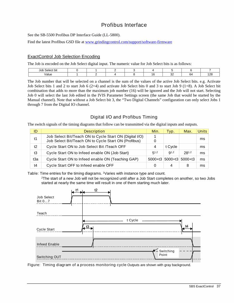
SBS ExactControl 37
Profibus Interface
See the SB-5500 Profibus DP Interface Guide (LL-5800).
Find the latest Profibus GSD file at www.grindingcontrol.com/support/software-firmware
ExactControl Job Selection Encoding
The Job is encoded on the Job Select digital input. The numeric value for Job Select bits is as follows:
Job Select bit 0 1 2 3 4 5 6 7
Value 1 2 4 8 16 32 64 128
The Job number that will be selected on a channel is the sum of the values of the active Job Select bits. e.g. Activate Job Select bits 1 and 2 to start Job 6 (2+4) and activate Job Select bits 0 and 3 to start Job 9 (1+8). A Job Select bit combination that adds to more than the maximum job number (16) will be ignored and the Job will not start. Selecting Job 0 will select the last Job edited in the IVIS Parameter Settings screen (the same Job that would be started by the Manual channel). Note that without a Job Select bit 3, the “Two Digital Channels” configuration can only select Jobs 1 through 7 from the Digital IO channel.
Digital I/O and Profibus Timing
The switch signals of the timing diagrams that follow can be transmitted via the digital inputs and outputs.
ID Description Min. Typ. Max. Units
t1 Job Select Bit/Teach ON to Cycle Start ON (Digital I/O) Job Select Bit/Teach ON to Cycle Start ON (Profibus)
1 0
ms
t2 Cycle Start ON to Job Select Bit /Teach OFF 4 t Cycle ms
t3 Cycle Start ON to Infeed enable ON (Job Start) 51,2 91,2 281,2 ms
t3a Cycle Start ON to Infeed enable ON (Teaching GAP) 5000+t3 5000+t3 5000+t3 ms
t4 Cycle Start OFF to Infeed enable OFF 0 4 8 ms
Table: Time entries for the timing diagrams. 1Varies with instance type and count. 2The start of a new Job will not be recognized until after a Job Start completes on another, so two Jobs started at nearly the same time will result in one of them starting much later.
Figure: Timing diagram of a process monitoring cycle Outputs are shown with gray background.
Infeed Enable
Switching OUT
Cycle Start
Teach
Job Select Bit 0…7
t Cycle
Switching Point

38 SBS ExactControl
Figure: Timing diagram for a process teaching cycle Outputs are shown with gray background.
Note that the Infeed enable is normally inactive. A broken connection will not enable the infeed. Note that the Switching output is normally active. A broken connection will typically end the cycle.
Flash memory Files
All process data for every process cycle operation is automatically recorded on the Flash memory. c_hhmmss.pct is the file name with c channel (see table), hh hour (24), mm minute, dd day of the file data. Saved file names identify the channel for the process data according to the following table:
channel Start signals via: Process signals reported via: filename
Digital I/O see page 35
SB-5500 Exact Control Card: digital inputs
SB-5500 Exact Control Card: digital outputs
D_hhmmss.PCT
Digital I/O 2 see page 35
SB-5500 ExactControl Card: digital inputs
SB-5500 ExactControl Card: digital outputs
N_hhmmss.PCT
Profibus 1 Profibus monitoring channel 1 Profibus monitoring channel 1 P_hhmmss.PCT
Profibus 2 Profibus monitoring channel 2 Profibus monitoring channel 2 R_hhmmss.PCT
Profibus 3 Profibus monitoring channel 3 Profibus monitoring channel 3 S_hhmmss.PCT
Profibus 4 Profibus monitoring channel 4 Profibus monitoring channel 4 T_hhmmss.PCT
Manual IVIS Button START JOB / STOP – M_hhmmss.PCT
The size of individual process cycle files in the Flash memory is limited to prevent a very long process cycle from filling the memory. This could prevent small processes from having any data stored. A file is closed when the process has used approximately 1/100 of the total Flash drive space. The process continues to operate without saving data. For a very complicated job with many high data rate instances only the first 1.5 hours of data would be saved (4G card). Simple jobs could save data for up to the first 18 hours.
Switching Point
Job Select Bit 0…7
Teach
Cycle Start
Infeed Enable
Switching OUT
t Cycle

SBS ExactControl 39
Error messages
Self-diagnostic software has been incorporated into all SB-5500 Control Units. If a problem ever occurs with an SBS system, It is reported on the user interface (IVIS) with an error code. Below is a listing of these error codes, a description of when the Control Unit automatically runs each test, how each code is cleared, the definition of each error message, and prescribed action to be taken by the user.
Some error messages can be manually cleared. When an error is cleared, it will be displayed again when the error condition is next detected. To further identify cause, a series of test operations accompany some of the error codes.
Make sure IVIS software and all control unit firmware are updated to the current released version found on the grindingcontrol.com website. If errors persist after the following steps, the user should start a detailed logfile in IVIS (see IVIS manual for details) and then provide this logfile (debug.html) to IVIS support engineers for review and assistance.
Please indicate any displayed Error message when returning equipment for repair. Also please provide as much detail as possible regarding the conditions when problems were encountered, and the symptoms experienced.
Error Code
Message Definition Action
A Sensor Open Checked continuously. Acoustic Sensor 1 or 2 presence not detected. This could be caused by a defective sensor or by no sensor being connected.
Clears automatically when sensor detected. Check sensor connections and try Power-On again. Continued error messages indicate the need for repairs to the Sensor.
B Sensor Shorted Checked continuously.
Acoustic Sensor 1 or 2 short circuit detected.
Clears automatically. Disconnect the Control Unit from AC power before checking cables and connectors, and sensor for shorts. If the problem cannot be isolated, the sensor, cable, and/or Control Unit should be returned for repair.
E +15V Defect Checked continuously. 15V Auxiliary supply low – fuse open
Check for shorts in Sensor and CNC cables and connectors and re-initialize the system. If the error persists return Control Unit and cables for repair. If you have the SBS system cabled to your CNC controller, verify that the CNC cable is free of electrical shorts. The CNC cable is not supplied with the SBS system, and repair is the responsibility of the user.
G Circuit failure Checked continuously. Signal acquisition circuit failed.
Clears automatically. No action required other than clearing manually from the screen. If the problem persists, the Control Unit should be returned for repair.
Many additional status messages can be displayed in IVIS, some important ones follow:
No learn cycle has been performed! AE Sensor parameters are not setup for use.
Firmware is too old - please update!
Card initialization failed!
Communication failure!
Can result from old version firmware on control unit, update firmware and restart system.

40 SBS ExactControl
Appendix A: Troubleshooting Issues
Flash memory initialization
When the control is started the Flash memory is not available for a short time (up to a minute) until it is fully initialized. Jobs will operate properly, but the data from the Job will not be stored in Flash memory. Only Jobs that are started after the Flash memory is initialized will be saved. There is no indication when the Flash memory is finished initializing. Initialization takes place on events such as: power-up; when ON/OFF is pressed on the SB-5500 front panel; when a front panel is connected; and following a firmware update.
Job Start with AE sensor
At any given time each of the two AE sensor circuits is operating with a specific set of circuit settings; sensor, gain, and frequency band. The sensor setting selects one of its three or four possible sensors. One circuit acquires signal from AE Sensor 1, 3, 5 or 7* and the other acquires signals from AE Sensor 2, 4, 6, or 8*. The system is unable to anticipate when any channel will start a Job. Prior to the start of a Job its selected circuit settings may not match the current circuit settings. Since every Job learns its circuit settings from a separate Learn sequence, it is unlikely that two Jobs will have the same circuit settings. If the circuit settings change at the start of a Job, then two delays are imposed on the signal acquisition:
Absolute method: At the change of a circuit’s settings, the acquired signal is not correct until the circuit settles. This takes about 15ms. The first few ms Measurement signal for its instance will have unsettled data.
Relative method: In addition to the settling delays that occur for the absolute method, the Measurement signal that has been stored for the previous 1 second is not valid for the new circuit settings. The relative method uses an average of that stored data as the zero reference for the Measurement signal. Specifically, it uses the most recent time as specified with the Idling time parameter. The Job start must be delayed until valid data can be acquired for the calculation of that average. This delay is up to one second.
If a Job is repeated, i.e. the sensor selection and gain does not change between Jobs, there is no delay in signal acquisition. The issue discussed occurs only when a channel starts a Job that changes the sensor selection or gain.
*AE Sensors 7 and 8 are only available on the SB-5560-8 card.
File transfers
File transfer from the ExactControl Flash memory to IVIS may be slow if the file is very large. The transfer is even slower while any Job is actively monitoring a process.

SBS ExactControl 41
Appendix B: Specifications
SB-5500 Physical Features
Multiple Device Control - Four (4) available slots accept these control cards:
SB-5512 Mechanical wired balancers SB-5518 Hydro Balancers SB-5522 Acoustic Emissions Monitoring System SB-5523 ExactDress™ process monitoring SB-5560 ExactControl™ process monitoring SB-5532 Mechanical non-contact balancers SB-5543 Manual balance control
SB-4500 Compatible Operates with existing cables and sensors.
Display Type: Color TFT LCD Active area: 480H x 272V pixel 3.74 inch [95mm] x 2.12 inch [53.86mm]
Communication Interfaces Ethernet TCP/IP, USB 2.0, Profibus DP, CNC/PLC
DC or AC Power Options
DC Supply: Input 21 VDC to 28 VDC. 5.5A max at 21 VDC. Reverse voltage protected.
Connector: Molex 50-84-1030 or equiv. Contacts: Molex 02-08-1002 or equiv.
AC Supply: 100-120 VAC, 50/60 Hz, 2A max; 200-240 VAC, 50/60 Hz, 1A max. Main supply voltage fluctuations not to exceed +/-10% of nominal supply voltage.
Environmental and Installation
Pollution degree 2 Installation category II IP54, NEMA 12 Environmental temperature range: 5°C to +55°C
SB-5560 Physical Features
Battery life (clock): Service life – 10 years
Flash memory: 4 GB
25 Pin DSUB Connector Interface
Analog Inputs: -10VDC to +10VDC operating range, reference to
common system ground. -18VDC to +18VDC absolute max range. 16 bit data resolution 150K Ohm to 180K Ohm input impedance.
CNC Digital Inputs and Outputs:opto-isolated from system signals to at least 500V. require common external 24VDC supply
Outputs: active: drive up to 50 mA per output inactive: high impedance down to -30 V referenced
to the common. Require flyback protection when driving coil.
Inputs: -3VDC to 30VDC absolute max range. Inputs are active with +18V to 30V DC applied
relative to common active inputs draw 5ma @ 24V (4.8mA to 5.2mA). Inputs are inactive with -3VDC to +5VDC applied
relative to common. high speed inputs can each react to a 2 µs pulse.
IVIS Features
Multi-language Capability English, German, Italian, French, Danish, Swedish, Hungarian, Chinese, Slovak, Polish, Russian, Spanish, Romanian, Portuguese

42 SBS ExactControl
Appendix C: Replacement Parts List
PN Description
AEMS SensorsSB-42xx Bolt-on Sensor SB-41xx AE-Extension Cable SB-3208 AE Sensor: Non-contact spindle mounted Mini-Stud Mount – M6x1.0 LH SB-3209 AE Sensor: Non-contact spindle mounted Mini-Stud Mount – M6x1.0 RH SB-3225 AE Sensor/ Sender Package: Non-Contact In-Spindle SB-3210 AE Sensor: Non-Contact In-Spindle w/ slide tube connection SB-5560-F AE Expansion panel – Adds 2 ExactControl dual input connectors using 2nd slot SB-4100 AE Sensor Cable adapter “Y” – Connects 2 AE Sensors to a single card input
Controls/Options SB-43xx Remote Keypad Cable for SB-5500 SB-5560 Additional ExactControl Card SB-5512 Additional Mechanical Balancer Card SB-5518 Additional Hydrokompenser (water balancer) Card SB-5522 Additional AEMS Gap/Crash Monitoring Card
SB5500 Control Mounting Hardware Options SK-5000 Rack Panel: SB-5500, Full Wide w/ 1/2 Blank, 3U SK-5001 Rack Panel: SB-5500, Partial Wide 3U w/ Handles SK-5002 Rack Panel: SB-5500, 1/2 Rack 3U Bracket SK-5003 Control Mount: SB-5500, Bottom Flange SK-5004 Control Mount: SB-5500, 90 Deg. Bracket, Cabinet SK-5005 Keypad Mount: Flush Panel Frame Kit
Other Parts EC-5605 A/C Control Fuse, 3 amp time lag 5x20 (2 required) EC-5614 D/C Control Fuse, 6.3 amp time lag 5x20 CA-0009 Power Cordset CA-0009-G Power Cordset (Germany) CA-0009-B Power Cordset (British)
xx in P/N = cable length in feet Standard options 11 [3.5m], 20 [6.0m], or 40 [12.0m], e.g. SB-4811 = 11ft [3.5m]
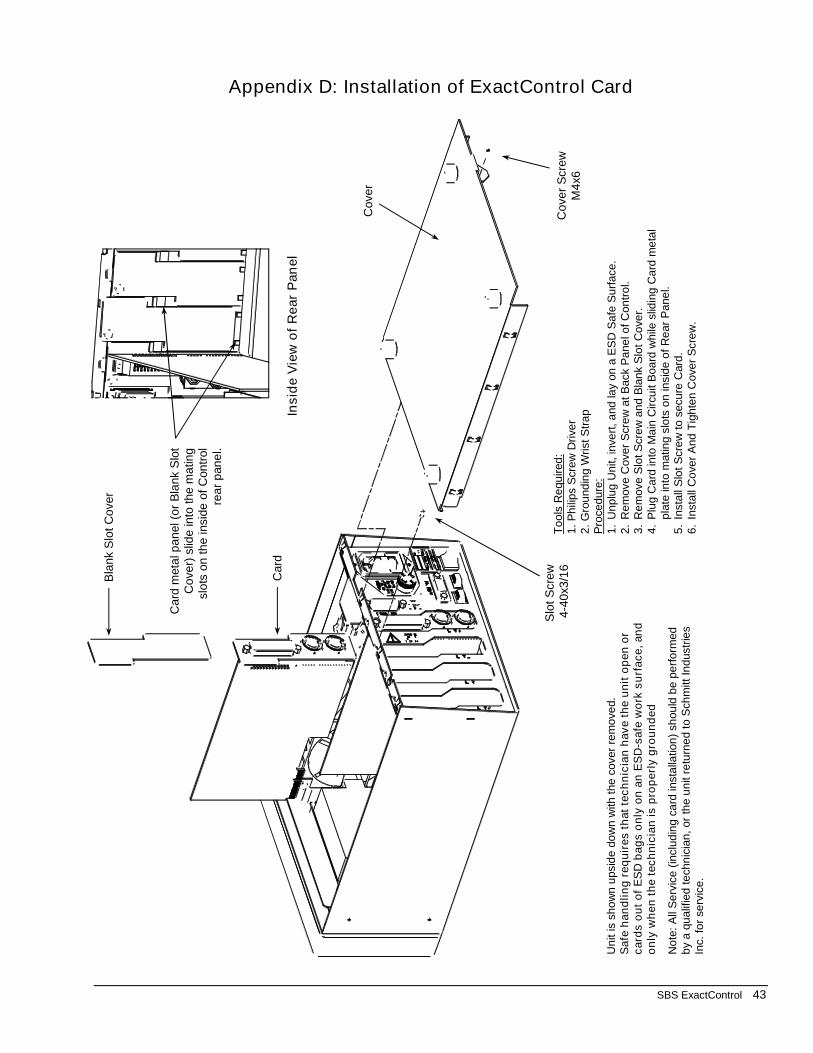
SBS ExactControl 43
Appendix D: Installation of ExactControl Card
To
ols
Re
qu
ired
:1
. P
hili
ps S
cre
w D
rive
r2
. G
rou
nd
ing W
rist S
tra
pP
roce
dure
:1
.U
np
lug
Unit, in
vert
, a
nd
lay
on
a E
SD
Sa
fe S
urf
ace.
2.
Re
move C
over
Scr
ew
at B
ack P
ane
l of C
on
tro
l.3
.R
em
ove S
lot S
cre
w a
nd
Bla
nk
Slo
t C
ove
r.4
.P
lug C
ard
into
Ma
in C
ircu
it B
oa
rd w
hile
slid
ing
Ca
rd m
eta
l p
late
into
matin
g s
lots
on in
sid
e o
f R
ear
Pane
l.5
.In
sta
ll S
lot S
cre
w to
secu
re C
ard
.6
.In
sta
ll C
ove
r A
nd
Tig
hte
n C
ove
r S
cre
w.
Un
it is
sh
ow
n u
psid
e d
ow
n w
ith the
cover
rem
ove
d.
Sa
feh
an
dli
ng
re
qu
ire
s t
hat
tec
hn
icia
n h
av
e t
he
un
it o
pe
n o
r c
ard
s o
ut
of
ES
D b
ag
s o
nly
on
an
ES
D-s
afe
wo
rk s
urf
ace
, an
d
on
ly w
he
n t
he
tec
hn
icia
n is
pro
pe
rly g
rou
nd
ed
No
te:
All
Se
rvic
e (
inclu
din
g c
ard
insta
llatio
n)
shou
ld b
e p
erf
orm
ed
b
y a
qu
alif
ied
te
chn
icia
n, or
the u
nit
retu
rne
d t
o S
chm
itt In
dustr
ies
Inc.
for
serv
ice.
Ca
rdm
eta
l pa
nel (o
r B
lank S
lot
Co
ve
r) s
lide
into
th
e m
atin
g
slo
ts o
n t
he insid
e o
f C
on
trol
rea
r p
an
el.
Insid
e V
iew
of
Re
ar
Pan
el
Co
ve
r S
cre
wM
4x6
Co
ve
r
Slo
tS
cre
w4
-40
x3/1
6
Ca
rd
Bla
nk
Slo
t C
ove
r