operation manual force gauge - pce instruments · pdf filemeasurements which do not require a...
TRANSCRIPT

OPERATION MANUAL
FORCE GAUGE
FG Series

2 OPERATION MANUAL
Contents:
1. Introduction ___________________________________________________________ 3
2. Set 3
3. Safety instructions _____________________________________________________ 4
4. Rules for handling a worn force gauge______________________________________ 4
5. Technical data_________________________________________________________ 5
6. Keys and indicators ____________________________________________________ 6
7. Preparing the force gauge for operation_____________________________________ 7
8. General rules for use ___________________________________________________ 8
9. Turning on the gauge ___________________________________________________ 9
10. Description of measurement methods _____________________________________ 10
10.1 Measuring actual and peak value of a pressure/pull force ___________________ 10
10.2 Measurement of the mass – using the gauge as scales_____________________ 11
11. Connecting external devices_____________________________________________ 14
12. User’s Menu _________________________________________________________ 15
13. Applications__________________________________________________________ 15
13.1 Data memory _____________________________________________________ 16
13.2 Comparison with threshold values MIN / OK / MAX ________________________ 19
14. Units _______________________________________________________________ 20
15. Configuration_________________________________________________________ 21
15.1 Speed of measurement______________________________________________ 21
15.2 Auto-reset ________________________________________________________ 22
15.3 Print settings ______________________________________________________ 23
15.4 Setting parameters for the RS-232C serial connector ______________________ 24
15.5 LCD settings ______________________________________________________ 25
15.6 Selecting the menu language _________________________________________ 26
15.7 Setting date and time _______________________________________________ 26
15.7 Setting date and time _______________________________________________ 27
15.8 Turning the sound ON/OFF when using the keypad (buzzer) ________________ 28
15.9 Automatic power OFF (Auto-OFF) _____________________________________ 28
15.9 Automatic power OFF (Auto-OFF) _____________________________________ 29
15.10 Monitoring the batteries’ charge level (Battery) ___________________________ 29
15.10 Monitoring the batteries’ charge level (Battery) ___________________________ 30
15.11 Reset settings _____________________________________________________ 31
16. Calibration___________________________________________________________ 31
16. Calibration___________________________________________________________ 32
17. Maintenance, troubleshooting and repairing minor types of damage______________ 33
OPERATION MANUAL 3
1. Introduction
The FG series force gauges are designed for measuring pressure or pulling force in laboratory, manufacturing and quality control applications.
The gauge can be held in hand or mounted on a stand (using the four threaded
holes at the bottom of the enclosure).
The RS232C serial connector allows the measurement results to be transmitted to a
computer or a printer for further analysis or recording.
2. Set
The basic set includes the following elements:
1. Force gauge,
2. Push tips – 4 pcs, 1 hook tip, 1 extension piece
3. Power supply unit ~230 V 50 Hz / =12 V; 1.25 A,
5. SK-1 cord (dynamometer – computer), 6. SK-1 cable, 7. CD containing an operation manual and software, 8. Warranty.
4 OPERATION MANUAL
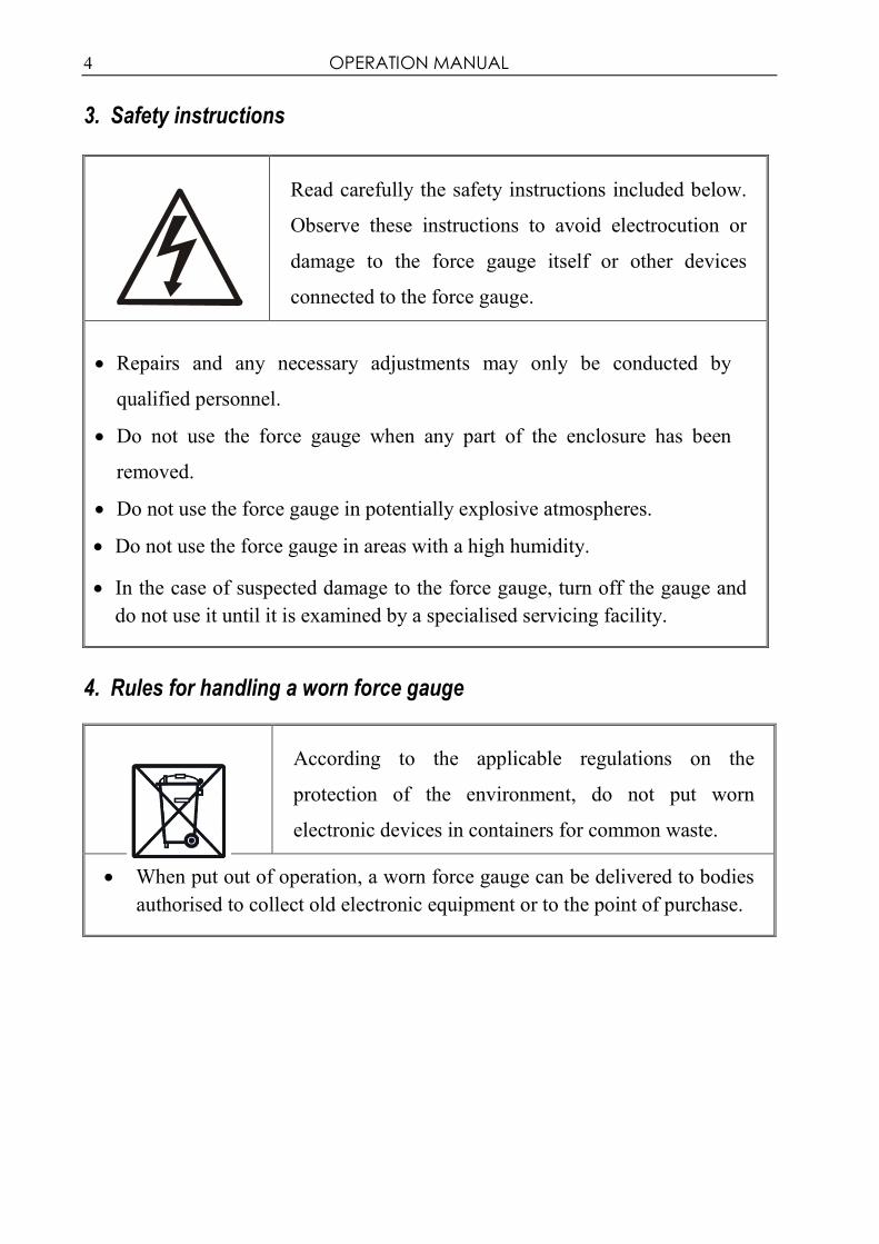
3. Safety instructions
Read carefully the safety instructions included below.
Observe these instructions to avoid electrocution or
damage to the force gauge itself or other devices
connected to the force gauge.
• Repairs and any necessary adjustments may only be conducted by
qualified personnel.
• Do not use the force gauge when any part of the enclosure has been
removed.
• Do not use the force gauge in potentially explosive atmospheres.
• Do not use the force gauge in areas with a high humidity.
• In the case of suspected damage to the force gauge, turn off the gauge and
do not use it until it is examined by a specialised servicing facility.
4. Rules for handling a worn force gauge
According to the applicable regulations on the
protection of the environment, do not put worn
electronic devices in containers for common waste.
• When put out of operation, a worn force gauge can be delivered to bodies
authorised to collect old electronic equipment or to the point of purchase.

OPERATION MANUAL 5
5. Technical data
Type FG50 FG200 Maximum force measured 50 N (5kg) 200 N (20kg)
Reading graduation (d) 0.01 N (1 g) 0.1 N (10 g)
Accuracy ±0.4% ±0.4% Measurement units N, g, lb, oz, kg
Maximum overload ±120% Operating temperature -10 ÷ 40°C Interface RS-232C
Assistance software Procell + Excel spreadsheet Display graphic LCD 61 x 34 mm
Measurement functions
Power supply NiMH R3 batteries (AAA size) – 6 pcs
+ power supply unit ~230 V 50 Hz / 12 V 1.2 A
Gauge plunger 11 mm (thread M6 x 9 mm)
Dimensions 210 x 110 x 40 mm Weight 700 g

6 OPERATION MANUAL
6. Keys and indicators
Main keys: ON/OFF - ON / OFF key (standby),
UNIT/CLEAR - Change units / cancel selection or change a parameter value, BACKLIGHT - Turn on illumination (ECO mode),
ENTER - Confirm / select an option or a digit, →T←
(→0←)
- Taring / resetting (entering the current reference value to be subtracted from the measured values in each consecutive measurement)
Navigation keys:
MENU - Confirm the entered parameter or select a highlighted option, ↑ - Move cursor up or increase the digit marked by the cursor,
↓ - Move cursor down or decrease the digit marked by the cursor,
→ - Move to the next menu level or display the next option,
← - Move to the previous menu level or display the previous option.
Function Keys:
PEAK - Measure the maximum value,
MEM - Save the result to the memory, press and hold – save to memory menu, PRINT - Print result (transmission via RS-232C connector).
Indicators:
- Indicates that the weighing result has stabilised, OFF - Appears after turning off the gauge using the ON/OFF key (standby),
SLW/FST - Slow/fast measurement mode, ACQ - Automatically acquire measurement results.
Note: Numbers are entered using the navigation keys. First, the cursor is placed in the right digit position.

OPERATION MANUAL 7
7. Preparing the force gauge for operation
1. Take the gauge out of the case. 2. Fit a measurement tip suitable for the measurements to be conducted on the gauge plunger.
Intended use of the individual tips:
- tip A – measurement of surface pressure force, - tip B – measurement of point pressure force, - tip C – measurement of pressure on an axis or an edge, - tip D – measurement of edge pressure force, - tip E – hook for measuring pull force or suspending and weighing an object, - tip F – extension piece suitable for all types of above-mentioned tips.
If the force gauge has been transported from an area with low
temperature to an area with a higher temperature, e.g. during
winter, water may condensate on the gauge’s enclosure. In such a
case, do not turn on the gauge’s power supply, as it may lead to
damage to the gauge or improper operation. Before turning on the
gauge, leave it for 1 hour to acclimatise.
Tip A
Tip B
Tip C
Tip D
Tip E
(hook)
Extension
piece F

8 OPERATION MANUAL
8. General rules for use
1. When conducting measurements by hand, make sure that the direction of the
measured force is identical with the gauge’s axis (axis of the gauge plunger).
Otherwise, only a component force along the gauge’s axis will be measured.
2. The gauge allows for resetting in the entire measurement range (this operation is
called taring in the case of measuring the mass) by pressing the →T(0)← key. Resetting/taring does not extend the measurement range but only subtracts the
entered reference value from the measured value.
3. The measurement mechanism is a precision device and is sensitive to shocks and vibrations. It is not allowed to hit the measurement tip against any objects.
4. Do not overload the gauge above the maximum overload value (20%).
When transporting the force gauge, unscrew the measurement tip and put the gauge in the case to protect it against accidental pressure on the gauge plunger.
OPERATION MANUAL 9
9. Turning on the gauge
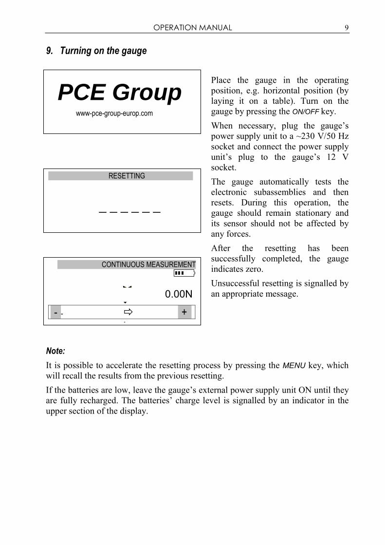
Place the gauge in the operating
position, e.g. horizontal position (by
laying it on a table). Turn on the
gauge by pressing the ON/OFF key.
When necessary, plug the gauge’s
power supply unit to a ~230 V/50 Hz
socket and connect the power supply
unit’s plug to the gauge’s 12 V
socket.
The gauge automatically tests the
electronic subassemblies and then
resets. During this operation, the
gauge should remain stationary and
its sensor should not be affected by
any forces.
After the resetting has been
successfully completed, the gauge
indicates zero.
Unsuccessful resetting is signalled by
an appropriate message.
Note:
It is possible to accelerate the resetting process by pressing the MENU key, which
will recall the results from the previous resetting.
If the batteries are low, leave the gauge’s external power supply unit ON until they
are fully recharged. The batteries’ charge level is signalled by an indicator in the
upper section of the display.
RESETTING
_ _ _ _ _ _
CONTINUOUS MEASUREMENT
0.00N �
- - � + �
PCE Group www-pce-group-europ.com
10 OPERATION MANUAL
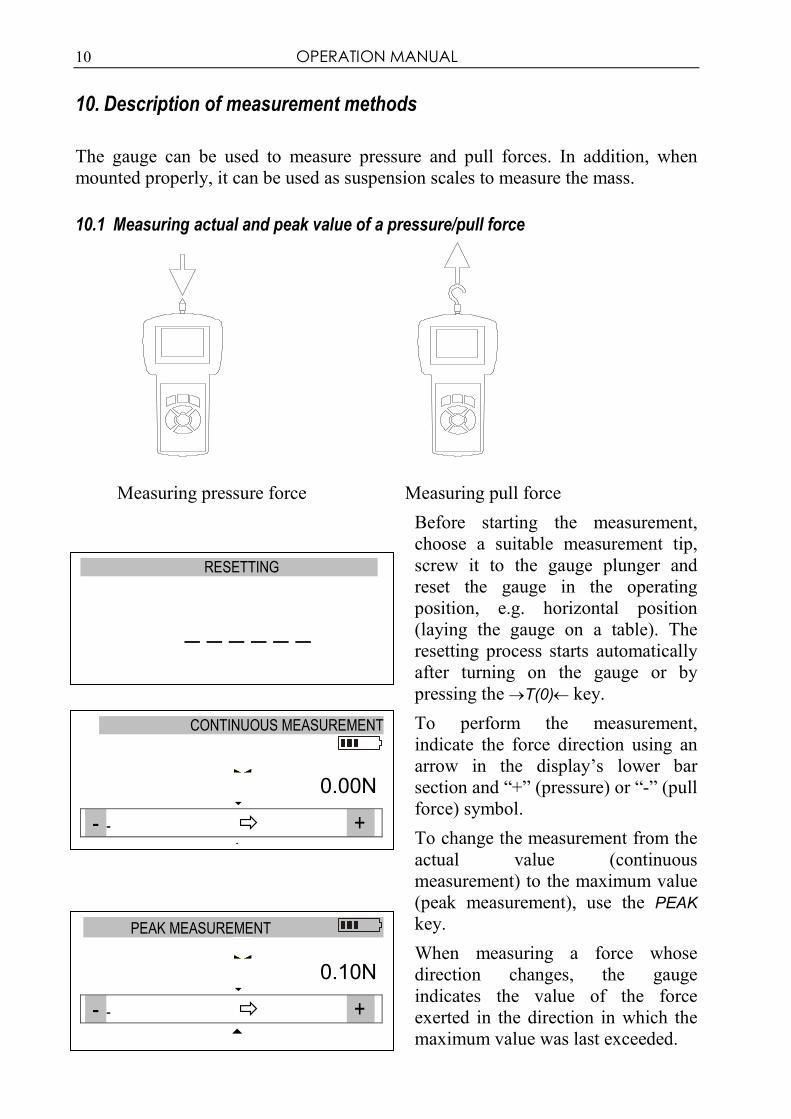
10. Description of measurement methods
The gauge can be used to measure pressure and pull forces. In addition, when
mounted properly, it can be used as suspension scales to measure the mass.
10.1 Measuring actual and peak value of a pressure/pull force
Measuring pressure force Measuring pull force
Before starting the measurement,
choose a suitable measurement tip,
screw it to the gauge plunger and
reset the gauge in the operating
position, e.g. horizontal position
(laying the gauge on a table). The
resetting process starts automatically
after turning on the gauge or by
pressing the →T(0)← key.
To perform the measurement,
indicate the force direction using an
arrow in the display’s lower bar
section and “+” (pressure) or “-” (pull
force) symbol.
To change the measurement from the
actual value (continuous
measurement) to the maximum value
(peak measurement), use the PEAK
key.
When measuring a force whose
direction changes, the gauge
indicates the value of the force
exerted in the direction in which the
maximum value was last exceeded.
CONTINUOUS MEASUREMENT
0.00N �
- - � + �
PEAK MEASUREMENT
0.10N �
- - � + �
RESETTING
_ _ _ _ _ _

OPERATION MANUAL 11
10.2 Measurement of the mass – using the gauge as scales
When using an additional element (bowl, basket, etc.) for suspending an object to
be weighed, the gauge can be used to measure the mass. In the case of
measurements which do not require a high level of precision, the gauge can be
hand-held. To ensure maximum precision of the measurement, the gauge should be
mounted on a stand using the four threaded holes at the bottom of the enclosure or
it can be suspended using a special suspension element (option available on
request).
Since the value of the gravity force used to calculate the mass depends on the
gravitational acceleration in the location where the gauge is used, the device is
calibrated for a specific value of the gravitational acceleration. The factory preset
value is the gravitational acceleration in Gdańsk (gR = 9.81415 m/s2). In the case of
significant differences, see the value applicable for the gauge’s shipment address.
When transporting the gauge to a location where the gravitational acceleration
differs significantly, recalibrate the gauge.
The values of the gravitational acceleration for some of the Polish cities are
presented in the table below.
Gravitational acceleration for selected cities City gR[m/s
2] City gR[m/s
2]
AXIS 9.81415 Olsztyn 9.81354
Gdańsk 9.81446 Łódź 9.81164
Gdynia 9.81453 Mława 9.81295
Białystok 9.81294 Opole 9.81076
Bydgoszcz 9.81327 Piła 9.81330
Chojnice 9.81342 Poznań 9.81266
Cieszyn 9.80960 Przemyśl 9.80991
Częstochowa 9.81061 Przeworsk 9.81009
Elbląg 9.81430 Radom 9.81146
Ełk 9.81361 Rybnik 9.81008
Gliwice 9.81025 Rzeszów 9.81010
Gorzów Wielkopolski 9.81305 Słupsk 9.81449
Grudziądz 9.81368 Suwałki 9.81377
Kalisz 9.81184 Szczecin 9.81370
Katowice 9.81008 Tarnów 9.81005
Kielce 9.81063 Toruń 9.81313
Koszalin 9.81427 Warszawa 9.81240
Kraków 9.81005 Włocławek 9.81288
Leszno 9.81206 Wrocław 9.81131
Lublin 9.81128 Zielona Góra 9.81190

12 OPERATION MANUAL
Measurement Measurement using a gauge
using a hand-held gauge mounted on a stand
(stand available on request)
Suspended weight measurement
(suspension element available on request)

OPERATION MANUAL 13
Screw the hook tip to the gauge
plunger, suspend a bowl on the
hook and place the gauge in the
operating position (as shown in the
figure). The display’s indications
will rotate by 180o.
To change force units to mass
units, press the UNIT/CLEAR or
MENU key several times. When
using the MENU key, move the
cursor to Units and press ENTER.
Move the cursor to a mass unit
(kilogram or gram) and press
ENTER.
Reset the gauge in the operating
position by pressing the →T(0)←
key.
Place the object to be weighed on
the bowl.
Read the mass.
RESETTING
_ _ _ _ _ _
USER’s MENU
1. Applications 2. Units 3. Configuration 4. Calibration 5. Exit
CONTINUOUS MEASUREMENT
0.2kg �
- -
+
UNITS
Kilogram [kg]
Gram [g]
Pound [lb]
Ounce [oz]
Newton [N]
Exit

14 OPERATION MANUAL
11. Connecting external devices
The force gauge is equipped with a socket for an external power supply unit and
RS232C serial connector for a printer or a computer.
PL EN
ZASILACZ POWER SUPPLY UNIT
masa earth
Description of the data transmission protocol when working with a computer
(LonG):
The scales transmit the result as follows (8 bits, 1 stop, no parity, 4,800 bps):
Computer→Gauge: initiating signal S I CR LF (53 h 49 h 0Dh 0 Ah),
Gauge→Computer: gauge indication according to the following format (16 bytes).
Description of individual bytes:
byte 1 - “-“ or space
byte 2 - space
byte 3÷4 - digit or space
byte 5÷9 - digit, comma or space
byte 10 - digit
byte 11 - space
byte 12 - k, l, c, p or space
byte 13 - g, b, t, c or %
byte 14 - space
byte 15 - CR
byte 16 - LF
1 - 2 - 3 - 4 -
RxD masaTxDNC
RS232CZASILACZ
OPERATION MANUAL 15
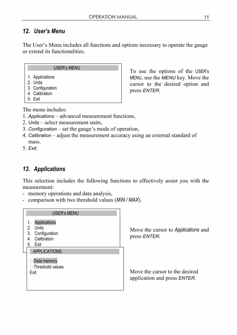
12. User’s Menu
The User’s Menu includes all functions and options necessary to operate the gauge
or extend its functionalities.
To use the options of the USER’s
MENU, use the MENU key. Move the
cursor to the desired option and
press ENTER.
The menu includes:
1. Applications – advanced measurement functions, 2. Units – select measurement units, 3. Configuration – set the gauge’s mode of operation, 4. Calibration – adjust the measurement accuracy using an external standard of mass.
5. Exit.
13. Applications
This selection includes the following functions to effectively assist you with the
measurement:
- memory operations and data analysis, - comparison with two threshold values (MIN / MAX).
Move the cursor to Applications and press ENTER.
Move the cursor to the desired
application and press ENTER.
USER’s MENU
1. Applications 2. Units 3. Configuration 4. Calibration 5. Exit
APPLICATIONS
Data memory
Threshold values Exit
USER’s MENU
1. Applications 2. Units 3. Configuration 4. Calibration 5. Exit

16 OPERATION MANUAL
13.1 Data memory
The Data memory application allows for the following:
- presentation of the collected measurements, saving, reading, erasing memory (Statistics),
- selecting the mode for collecting data, - exit.
Move the cursor to Applications and press ENTER.
Move the cursor to Data memory and press ENTER.
Setting the mode for collecting
data:
- MANUAL – each time after MEM is pressed,
- AUTO – automatically at specified intervals.
After selecting AUTO, enter the number of samples (max 100) and
sampling time (0.1÷99.9 s.).
To start the collection of
measurements, exit the menu and
press MEM several times or press MEM for automatic save. When in
the automatic save mode, press and
hold MEM to go to the data save menu.
USER’s MENU
1. Applications 2. Units 3. Configuration 4. Calibration
5. Exit
APPLICATIONS
Data memory
Threshold values
Exit
ENTER ← →
APPLICATIONS
1. Statistics 2. Mode <MANUAL> <AUTO> 3. Number of samples 100 4. Sampling time 0.1 sec 5. Exit
ENTER
APPLICATIONS
1. Statistics 2. Mode AUTO 3. Number of samples 100 4. Sampling time 0.1 sec 5. Exit
↑ ↓
APPLICATIONS
1. Statistics 2. Mode <MANUAL> <AUTO> 3. Number of samples 100 4. Sampling time 0.1 sec 5. Exit

OPERATION MANUAL 17
Presentation of collected measurements (Statistics)
The Statistics option allows for the following forms of presentation of the collected
data:
<PRINT> – transmission to a printer,
<HISTOGRAM> – bar graph,
<GRAPH> – graph with a time axis.
Move the cursor to Applications and press ENTER.
Move the cursor to Data memory and press ENTER.
Move the cursor to Statistics and press ENTER.
Select one of the options from the
lower menu bar:
- PRINT – transmission to a printer,
- HISTOGRAM – bar graph,
- GRAPH – graph with a time axis.
. . .
- RESET – erases the entire memory,
- DELETE – deletes a selected
memory file.
Indicators L... =... provide the
size of the bar indicated by the
↑ arrow.
To move the arrow (scroll the
graph), use the ← and → keys.
USER’s MENU
1. Applications 2. Units 3. Configuration 4. Calibration
5. Exit
APPLICATIONS
Data memory
Threshold values
Exit
DATA MEMORY
1. Statistics 2. Mode AUTO 3. Number of samples 100 4. Sampling time 0.1 sec 6. Exit
Statistics
Quantity 100 Sum 990 g Average 9 g MAX 12 g MIN 8 g
<PRINT><HISTOGRAM><GRAPH><SAVE><READ>
<RESET><DELETE><EXIT>
ENTER ← →
HISTOGRAM
MIN MAX
↑ <L01 = 8>

18 OPERATION MANUAL
Save, read, erase memory (Statistics)
The Statistics option allows for the following:
< SAVE > – saves the data currently presented,
< READ > – reads a file from the memory,
< RESET > – erases the data currently presented,
< DELETE> – deletes a selected data file.
Move the cursor to Applications and press ENTER.
Move the cursor to Data memory and press ENTER.
Move the cursor to Statistics and press ENTER.
The following options (lower bar)
will appear:
- . . .
- SAVE – saves the measurements
currently presented,
- READ – reads a measurement
file,
- RESET – erases the memory,
- EXIT – exits the option. Select the SAVE option.
Select a file (FILE) to be saved.
The default file name includes
date and time. Confirm the
default file name or enter another
name using the →, ←, ↑ and ↓
keys.
USER’s MENU
1. Applications 2. Units 3. Configuration 4. Calibration
5. Exit
APPLICATIONS
Data memory
Threshold values Exit
DATA MEMORY
1. Statistics 2. Mode <AUTO> 3. Number of samples 100 4. Sampling time 0.1 sec 5. Exit
ENTER ↑ ↓
SAVE DATA
2009-12-17 10:00 < FILE02 > . . . < FILE08 >
ENTER ↑ ↓
Statistics Quantity 100 Sum 990 g Average 9 g MAX 12 g MIN 8 g
<PRINT> ... <SAVE><READ> <RESET><EXIT>
SAVE DATA
< FILE01 > < FILE02 > . . . < FILE08 >

OPERATION MANUAL 19
13.2 Comparison with threshold values MIN / OK / MAX
This selection includes the following functions to effectively assist you with the
measurement:
- memory operations and data analysis, - comparison with two threshold values (MIN / MAX).
Move the cursor to Applications and press ENTER.
Move the cursor to Threshold values and press ENTER.
Activate the comparison by setting
Status to ON:
- enter the MIN value – lower threshold,
- enter the MAX value – upper threshold.
Select the option for sound
signalling (Buzzer):
- MODE1 – short signal upon exceeding MIN, long signal upon exceeding MAX, - MODE2 – interrupted signal below MIN, above MAX – continuous signal, for OK – no signal.
Exit the menu, start the
measurement and observe the MIN,
OK and MAX indicators on the
gauge’s display.
USER’s MENU
1. Applications 2. Units 3. Configuration 4. Calibration 5. Exit
APPLICATIONS
Data memory
Threshold values
Exit
CONTINUOUS MEASUREMENT
OK
0.00N �
- - � + �
THRESHOLD VALUES
1. Status <ON> <OFF> 2. MIN 1.000kg 3. MAX 2.000kg 4. Buzzer MODE1 5. Exit
ENTER ← →

20 OPERATION MANUAL
14. Units
The following units are available to the user:
- kilogram (kg)
- gram (g)
- Pound: 1 lb = 453.592374 g
- ounce: 1 oz = 28.349523 g
- Newton: 1 N = 0.10197 kg
To change the units, press the UNIT/CLEAR or MENU key several times.
Press the MENU key, move the
cursor to Units and press ENTER.
Move the cursor to the desired unit
and press ENTER.
USER’s MENU
1. Applications 2. Units 3. Configuration 4. Calibration
5. Exit
ENTER
UNITS
Kilogram [kg]
Gram [g]
Pound [lb]
Ounce [oz]
Newton [N] Exit

OPERATION MANUAL 21
15. Configuration
This selection includes all options for setting the gauge’s modes of operation.
Move the cursor to Configuration and press ENTER.
Move the cursor to the desired
option and press ENTER.
15.1 Speed of measurement
To obtain clear measurement results, it is recommended to adjust the speed of
measurement to the dynamic properties of the measured object.
Press ENTER to select one of the
options:
- SLOW – slow measurement,
- FAST – fast measurement.
USER’s MENU
1. Applications 2. Units 3. Configuration 4. Calibration
5. Exit
USER’s MENU
1. Applications 2. Units 3. Configuration 4. Calibration 5. Exit
SPEED OF MEASUREMENT
SLOW
FAST Exit
ENTER
CONFIGURATION
1. Speed of measurement 2. Auto-reset 3. Print settings 4. RS-232C settings 5. LCD settings 6. Language 7. Date and time 8. Auto-OFF 9. Battery 10. Default settings 11. Exit
CONFIGURATION
1. Speed of measurement 2. Auto-reset 3. Print settings 4. RS-232C settings 5. LCD settings

22 OPERATION MANUAL
15.2 Auto-reset
When activated, this option automatically maintains zero indications on the gauge,
if the gauge’s sensor is not affected by any external force or if the zero indication
was produced by pressing the →T(0)← key. The range of values (calculated in the gauge’s reading graduation near zero) subject to the reset must be entered under
the Range option (3 digits).
Use the navigation keys and
ENTER to select Status and one of
the following options:
- ON – auto-reset ON,
- OFF – auto-reset OFF.
Next, select Range and use ↑, ↓,
→, ← and ENTER to enter the
auto-reset range (in reading
graduation).
USER’s MENU
1. Applications 2. Units 3. Configuration 4. Calibration 5. Exit
ENTER ↑ ↓
ENTER
AUTO-RESET
1. Status <ON> <OFF> 2. Range 2 d
3. Exit
← →
CONFIGURATION
1. Speed of measurement 2. Auto-reset 3. Print settings 4. RS-232C settings 5. LCD settings
AUTO-RESET
1. Status <OFF> 2. Range 0 0 2 d 3. Exit

OPERATION MANUAL 23
15.3 Print settings
According to the requirements of GLP procedures, it is possible use an external
printer to produce print-outs from the gauge including text information.
Use the navigation keys and
ENTER to select Print settings and
the suitable print components.
ID1, ID2, ID2 – text strings (up to 20 characters) forming the lines of
the print-out, entered using the
gauge’s navigation keys.
To enter the characters, select ID
using ENTER and press →. The
characters are entered using the
navigation keys ↑ and ↓. To move
the cursor to the consecutive
positions, use ← and →. To
confirm the entered string, press
ENTER. To delete a character,
enter space.
USER’s MENU
1. Applications 2. Units 3. Configuration 4. Calibration 5. Exit
PRINT SETTINGS
Heading
Date
Time
ID1>
ID2>
ID3>
Number
CONFIGURATION 1. Speed of measurement 2. Auto-reset 3. Print settings 4. RS-232C settings
↑
PRINT SETTINGS
Heading
Date
Time
ABCD
ID2
ID3
↓ ↓ ↑ ENTER
ENTER →

24 OPERATION MANUAL
15.4 Setting parameters for the RS-232C serial connector
The parameters of the serial connector must be suitable for the device receiving the
signal.
Parameters to be set:
- Baudrate – transmission and
receiving rate (4,800 ÷ 115,200
bps),
- Bits – number of bits which constitute a character (7 or 8 bits),
- Parity – control of parity (no control, even – confirmation of
parity, or odd – confirmation of
odd parity),
- Sending – transmission method
during measurement:
- NOCAL – after using the PRINT key, with stable result,
- NOSTB – after using the PRINT key, irrespectively of the result
stability,
- AUTOSTB – automatically after the result has stabilised,
- CONTIN. – continuous
transmission, approx. every 0.1
s.
USER’s MENU
1. Applications 2. Units 3. Configuration 4. Calibration 5. Exit CONFIGURATION
1. Speed of measurement 2. Auto-reset 3. Print settings 4. RS-232C settings 5. LCD settings
ENTER ↑ ↓
ENTER
RS-232C
1. Baudrate 4800 2. Bits 8-bit 3. Parity none 4. Sending <NORMAL><NO STB><AUTOSTB> <CONTIN.> 5. Exit
← →
RS-232C
1. Baudrate 4800 2. Bits 8-bit 3. Parity none 4. Sending NORMAL 5. Exit

OPERATION MANUAL 25
15.5 LCD settings
This option adjusts the gauge’s display to external lighting conditions.
Use the navigation keys and
ENTER to select LCD settings.
Next, use →, ← and ENTER to set
the contrast at which the display is
best legible.
When setting Illumination, select
one of the following options:
- OFF – illumination OFF,
- ON – illumination continuously
ON,
- ECO – to illuminate, use the
BACKLIGHT key,
- BAT – illumination is turned off
after 30 seconds to save the
batteries.
The DIRECTION option is used for
selecting the display’s direction:
- AUTO – automatic rotation of the
displayed image,
- UP – standard direction,
- DOMN – inverted image.
The LCD TIME option displays the
date and time during measurement
in the display’s upper bar.
↑ ↓
SETTINGS
1. Contrast < > 2. Illumination <ECO> 3. Direction <AUTO><UP><DOMN> 4. LCD time OFF 5. Exit
ENTER
SETTINGS
1. Contrast < > 2. Illumination <ON><OFF><ECO><BAT> 3. Direction 4. LCD time OFF 5. Exit
ENTER ← →
ENTER ← →
USER’s MENU
1. Applications 2. Units 3. Configuration 4. Calibration 2. Exit
CONFIGURATION
1. Speed of measurement 2. Auto-reset 3. Print settings 4. RS-232C settings 5. LCD settings
SETTINGS
1. Contrast 2. Illumination <ON> 3. Direction 4. LCD time OFF 5. Exit

26 OPERATION MANUAL
15.6 Selecting the menu language
Three menu languages are available:
<PL> – Polish,
<ENG> – English,
<DE> – German.
Use the navigation keys and
ENTER to select Language. To
select one of the available menu
languages, use the →, ← keys and ENTER.
To enter a new code (NEW), select
the PIN option. When entering a
new code, type in the same number
twice (message: REP.).
ENTER ← →
USER’s MENU
1. Applications 2. Units 3. Configuration 4. Calibration 5. Exit
CONFIGURATION
. . .
4. RS-232C settings 5. LCD settings 6. Language 7. Date and time 8. Auto-OFF
LANGUAGE
1. Language <PL><ENG><DE> 2. Exit

OPERATION MANUAL 27
15.7 Setting date and time
This option is used for entering the current date and time. Access to this setting is
secured by the PIN code.
Use the navigation keys and
ENTER to select Date and time. If a
PIN has already been entered
(other than 0), after selecting Time
or Date, the cursor will move to the
PIN option, where a correct 4-digit
PIN has to be entered. To enter the
correct digits, use the ↑, ↓, →, ←
keys and ENTER.
To enter a new code (NEW), select
the PIN option. When entering a
new code, type in the same number
twice (message: REP.).
The FORMAT option allows for the
selection of the date format on
print-outs.
ENTER ↑ ↓
USER’s MENU
1. Applications 2. Units 3. Configuration 4. Calibration
5. Exit
CONFIGURATION
3. Print settings 4. RS-232C settings 5. LCD settings 6. Language 7. Date and time
8. Auto-OFF
DATE AND TIME
1. Time hh:mm:ss 2. Date yyyy-mm-dd 3. PIN 0 4. Format <EU><USA> 5. Exit

28 OPERATION MANUAL
15.8 Turning the sound ON/OFF when using the keypad (buzzer)
This options turns ON or OFF the sound signalling that a key on the keypad has
been pressed. When the sound is turned on, the user usually does not apply
excessive force when pushing the keys.
Use the navigation keys and
ENTER to select Keypad and
Buzzer, and one of the following
options:
- ON – sound ON,
- OFF – sound OFF.
USER’s MENU
1. Applications 2. Units 3. Configuration 4. Calibration 5. Exit
ENTER ↑ ↓
← →
AUTO-OFF
1. Buzzer <ON> 2. Exit
ENTER
CONFIGURATION
3. Print settings 4. RS-232C settings 5. LCD settings 6. Date and time 7. Keypad
AUTO-OFF
1. Buzzer <ON><OFF> 2. Exit
OPERATION MANUAL 29
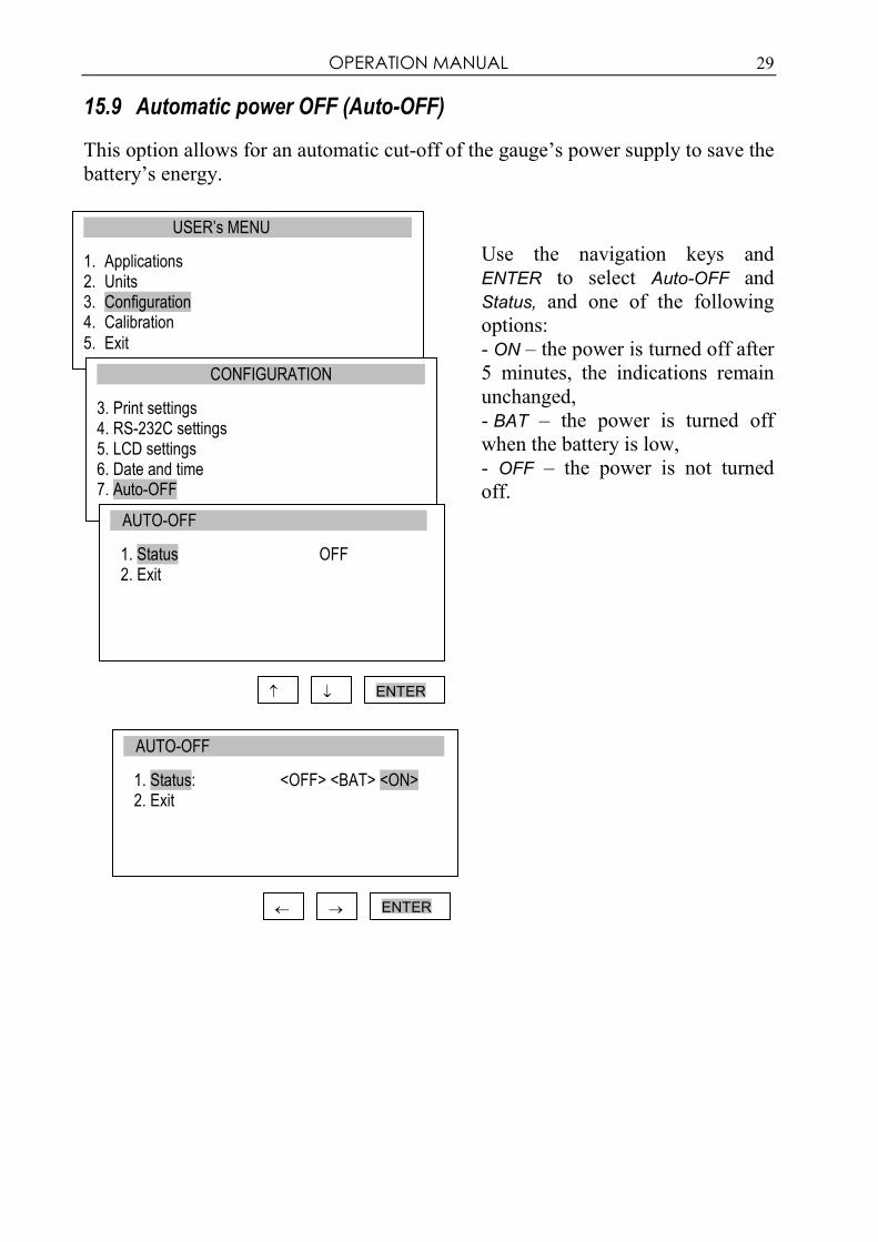
15.9 Automatic power OFF (Auto-OFF)
This option allows for an automatic cut-off of the gauge’s power supply to save the
battery’s energy.
Use the navigation keys and
ENTER to select Auto-OFF and
Status, and one of the following
options:
- ON – the power is turned off after
5 minutes, the indications remain
unchanged,
- BAT – the power is turned off
when the battery is low,
- OFF – the power is not turned
off.
USER’s MENU
1. Applications 2. Units 3. Configuration 4. Calibration
5. Exit
CONFIGURATION
3. Print settings 4. RS-232C settings 5. LCD settings 6. Date and time 7. Auto-OFF
ENTER
AUTO-OFF
1. Status OFF 2. Exit
↑ ↓
← →
AUTO-OFF
1. Status: <OFF> <BAT> <ON> 2. Exit
ENTER

30 OPERATION MANUAL
15.10 Monitoring the batteries’ charge level (Battery)
This option is used for reading the charge level of the batteries and allows for the
charging to be turned off to protect ordinary batteries, if such batteries are used
instead of rechargeable batteries.
Charging ordinary batteries used instead of rechargeable batteries
may lead to major damage to the gauge.
Use the navigation keys and
ENTER to select Battery and
Charging, and one of the following
options:
- ON – charging ON,
- OFF – charging OFF.
USER’s MENU
1. Applications 2. Units 3. Configuration 4. Calibration
5. Exit
ENTER ↑ ↓
BATTERY
1. Charging <OFF> <ON> 2. Charge level 80% 3. Exit
ENTER ← →
CONFIGURATION
5. LCD settings 6. Language 7. Date and time 8. Auto-OFF 9. Battery BATTERY
1. Charging OFF 2. Charge level 80% 3. Exit

OPERATION MANUAL 31
15.11 Reset settings
This option restores factory settings (default settings) for all options.
Use the navigation keys and
ENTER to select Reset settings and
the option YES.
As a result of restoring factory
settings, the gauge will reset and
start continuous measurement.
USER’s MENU
3. Applications 4. Units 5. Configuration 6. Calibration 7. Exit
CONFIGURATION
. . . 7. Date and time 8. Auto-OFF 9. Battery 10. Reset settings
ENTER ↑ ↓
RESET SETTINGS
Restore default settings? NO YES

32 OPERATION MANUAL
16. Calibration
To calibrate the gauge, select the method of applying load. For this purpose, use a
stand or suspend a standard of mass on the gauge.
Reset the gauge without load using
the →T(0)← key.
Use the navigation keys and
ENTER to select Calibration and Load.
Select the load depending on the
standard of mass. The <...> option
allows for entering any value.
Enter the gravitational acceleration
to correctly convert mass (kg) into
force (N).
If the exact “g” value is not
known, enter the parameters of the
geographical location (latitude and
above mean sea level). The “g”
value will be calculated
automatically.
Apply the standard of mass to the
gauge.
Use the navigation keys and
ENTER to select Calibration and
wait until the calibration process is
completed.
USER’s MENU
6. Applications 7. Units 8. Configuration 9. Calibration
10. Exit
ENTER ↑ ↓
CALIBRATION
1. Calibration 2. Load 5kg 3. g = 9.81416m/s2 4. Geographical location 5. Exit
CALIBRATION
1. Calibration 2. Load <5kg> <20kg><10kg><...> 3. g = 9.81416m/s2 4. Geographical location 5. Exit
ENTER ↑ ↓

OPERATION MANUAL 33
17. Maintenance, troubleshooting and repairing minor types of damage
1. Keep the gauge clean.
2. When using the force gauge, make sure that no contamination gets between the
gauge plunger and the enclosure. Upon identifying any contamination, remove
it using a tool which does not conduct electricity.
3. Unauthorised persons may not perform any repairs.
4. Have the gauge repaired by your local servicing facility. A list of servicing facilities is enclosed in the warranty.
Messages and faults:
Message/fault Cause Recommendation The message RESETTING is displayed for an extended
period of time.
Resetting process
disturbed Keep the gauge in motionless position
and press →T(0)←
Message: AD range exceeded (+/-)
Resetting process disturbed
Put the gauge in horizontal position and
turn it off and on using the ON/OFF key.
The values indicated by the
gauge diverge significantly
from correct values
Gauge out of
adjustment
Contact a servicing facility to calibrate
the gauge
Units displayed are different
from the selected units
UNIT/CLEAR key pressed by accident
Press the UNIT/CLEAR key several times to display the correct units

34 OPERATION MANUAL

OPERATION MANUAL 35
Notes

36 OPERATION MANUAL