operation manual fw - wici.com · operation manual fw – series flow monitor model: f012-p rate /...
TRANSCRIPT

OPERATION MANUALFW – SERIES FLOW MONITOR
MODEL: F012-PRATE / TOTALIZER
Signal input: coil, pulse, Namur
Hardware version : V02.01.03Software version : 01.01.xxManual : H_F012PEN_v010108.doc
Information in this manual might change without prior notice. The manufacturer is not responsible formistakes in this material or for incidental damage direct or indirect as a result of this delivery,performance or use of this material.
All rights reserved. No parts of this publication may be reproduced or used in any form or by anymeans without written permission of your supplier.
Warning: Any responsibility is lapsed if the instructions and procedures as described in this manualare not followed.
LIFE SUPPORT APPLICATIONS: The products F012-P-series are not designed for use in life supportappliances, devices, or systems where malfunction of the product can reasonably be expected toresult in a personal injury. Customers using or selling these products for use in such applications do soat their own risk and agree to fully indemnify the manufacturer and supplier for any damages resultingfrom such improper use or sale.
WARNING!! Electro static discharge does inflict irreparable damage to electronics!Before installing or opening the unit, the installer has to discharge himself bytouching a well-grounded object.¨
WARNING!! This unit must be installed in accordance with the EMC guidelines(Electro Magnetic Compatibility).

Page: 2
SAFETY RULES AND PRECAUTIONARY MEASURES-The manufacturer accepts no responsibility whatsoever if the instructions and procedures as described in this manual are not followed.- Modifications of the F012-P implemented without prior written consent from the manufacturer, will result in the immediate termination of product liability and warranty period.- The manufacturer accepts no responsibility whatsoever if the following safety rules and precautions are not observed.- Installation, use, maintenance and de-mounting of this equipment must be carried out by authorized technicians.- Check the mains voltage and information on the manufacturer's plate before installing the unit.- Check all connections, settings and technical specifications of the various peripheral devices and the rate/ totaliser F012-P.- Open the casing only if all leads are potential free.- Never touch the electronic components (ESD sensitivity).- Never expose the system to heavier conditions than allowed according to the casing classification (see manufacture's plate and chapter 4.2.).- If the operator detects errors or dangers, or disagrees with the safety precautions taken, then inform the owner or principal responsible.- The local labor and safety laws and regulations must be adhered to.
CONTENTS:Safety rules and precautionary measures..................................................................................................................................... 2Contents .............................................................................................................................................................................................. 21. Introduction ......................................................................................................................................................................... 31.1. About the operation manual............................................................................................................................. 31.2. Control panel ..................................................................................................................................................... 31.3. Brief description of the rate/Totalizer F012-P ............................................................................................... 32. Operational ......................................................................................................................................................................... 42.1. General ................................................................................................................................................................ 43. Configuration....................................................................................................................................................................... 53.1. Introduction.......................................................................................................................................................... 53.2. Programming SETUP-level.............................................................................................................................. 53.2.1. General ................................................................................................................................................................ 53.2.2. Prog-procedure .................................................................................................................................................. 73.2.3. SETUP.................................................................................................................................................................. 73.2.3.1. Total - 1................................................................................................................................................................. 73.2.3.2. Flowrate - 2.......................................................................................................................................................... 83.2.3.3. Display - 3............................................................................................................................................................ 83.2.3.4. Power management - 4..................................................................................................................................... 93.2.3.5. Flowmeter - 5...................................................................................................................................................... 93.2.3.6. Others - 6........................................................................................................................................................... 104. Installation ........................................................................................................................................................................ 114.1. General directions ........................................................................................................................................... 114.2. Installation / surrounding conditions ............................................................................................................ 114.3. Dimensions........................................................................................................................................................ 114.4. Installing the hardware.................................................................................................................................... 124.4.1. Introduction........................................................................................................................................................ 124.4.2. Voltage supply flowmeter pick-up.................................................................................................................. 124.4.3. Terminal connectors......................................................................................................................................... 135. I ntrinsic safety connections ............................................................................................................................. 166. Maintenance...................................................................................................................................................................... 226.1. General directions ........................................................................................................................................... 22Appendix A: Technical specification F012-P...................................................................................................................... 23Appendix B: Problem solving................................................................................................................................................ 24Index: ..................................................................................................................................................................................................25Notes: .................................................................................................................................................................................................26List of actual settings F012-P.......................................................................................................................................................... 28

Page: 3
1. INTRODUCTION
1.1. ABOUT THE OPERATION MANUALThis operation manual is divided into two main sections;
The daily use of the unit is described in chapter 2 “Operation”. This instruction is meant for users.The following chapters and appendices are exclusively meant for electricians/technicians. Theseprovide an extensive description of all software settings and installing the hardware.
11 SETUP-REFERENCESIn the margin of this manual, SETUP-references have been included so that explanations regardingSETUP-level can easily be looked up; 11 in this case, for example.
1.2. CONTROL PANEL
Following keys are available:
Fig. 1: Control Panel.
Functions of the keys:
• PROG / ENTER : This key has no function at operator level.It is used only to configure the unit; please read chapter 3.
• SELECT / � This key is used to SELECT accumulated total.The arrow-key � is only used to configure the unit; please read chapter 3.
• CLEAR / �Press this key twice to CLEAR the actual value for Total.The arrow-key � is only used to configure the unit; please read chapter 3.
1.3. BRIEF DESCRIPTION OF THE RATE/TOTAL IZER F012-P
The rate/totaliser F012-P is a system driven by microprocessors for the displaying of flow rate, Totaland accumulated Total. For that purpose, one flow meter with pulse or coil output can be connected tothe F012-P.
The F012-P is designed to be implemented in many types of applications. For that reason, a SETUP-levelis available to configure your rate/ totaliser best according to your requirements. SETUP includesseveral important features as K-factors and measurement units.Normally, the unit has to be powered with 8-30V DC. Optional available is battery powered.To extend the battery-life time, please make use of the power-management functions as described inchapter 3.2.3.3.
With the intrinsically safe option, Model F012-P-XI can be installed in hazardous area accordingEEx ia IIB/IIC T4. Please read chapter 5 for more information.

Page: 4
2. OPERATIONAL
2. 1. GENERAL
This chapter describes the daily use of the rate/totaliser. This instruction is meant for the users /operators.
In general, the rate/ totaliser will always act at Operator level. The information displayed is dependingon the SETUP-settings. Although the refresh-rate of the display might be slow (due to power-managementfunctions), each flow meter pulse will be measured. After pressing a key, the display willbe updated very fast during 30 seconds after which it will slow-down again.
Fig. 2: Example display information during process.
For the Operator, following functions are available:
• Display rate/Total or rate:This is the main display information of the F012-P. After selecting other information, it willreturn to the main display automatically. The actual flow rate is either displayed at the bottomline or with the 17mm digits at the upper line. When “———” is shown, the flow rate value istoo high to be displayed. The arrows � indicate the increase/decrease of the flow rate.
• Clear Total:The value for Total can be initialized. To do so, press CLEAR twice. After pressing CLEARonce, the text “PUSH CLEAR” is displayed while the display information is flashing. To avoidinitialization in that stage, press a different key or wait for 20 seconds. Initialization of TotalDOES NOT influence accumulated Total.
• Display accumulated Total:When the SELECT-key is pressed, Total and Accumulated Total are displayed. AccumulatedTotal can never be initialized. The value wi ll count up to 99,999,999,999. The unit andnumber of decimals are according to Total.
• Low-battery alarm:When the battery voltage drops, it must be replaced. First “low-battery” will flash, but as soonas it is displayed continuously, the battery MUST be replaced soon! Only official batteriesmay be used, else the guarantee will be terminated. The remaining life time after the firstmoment of indication is in general several days up to some weeks.
Fig. 3: Example of low-battery alarm.
• Alarm 01-04:When “alarm” is displayed, please consult Appendix B: problem solving.
TOTAL
RATE
m�
TOTAL
RATE
m�
Page: 5
3. CONFIGURATION
3.1. INTRODUCTION
This and following chapters are exclusively meant for electricians and non-operators. In these, anextensive description of all software settings and hardware connections are provided.
• Authorized technicians must carry out installation, use, maintenance and de-mountingof this equipment only.
• Take good notice of the “Safety rules and precautionary measures” in the front ofthis manual.
3.2. PROGRAMMING SETUP-LEVEL
3.2.1. GENERAL
Configuration of the F012-P is done at SETUP-level. SETUP-level can be reached by pressing thePROG/ENTER key for 7 seconds; in the meantime both arrows � are displayed. In order to return tothe operator level, PROG will have to be pressed for three seconds. Also, when no keys are pressedfor 2 minutes, SETUP will be left automatically.SETUP can be reached at all times while the F012-P remains full operational.
Password:A password may be required to enter SETUP. Without this password access to SETUP is denied.
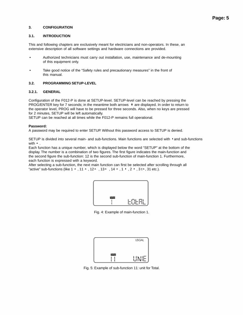
SETUP is divided into several main- and sub-functions. Main functions are selected with �and sub-functionswith � .Each function has a unique number, which is displayed below the word “SETUP” at the bottom of thedisplay. The number is a combination of two figures. The first figure indicates the main-function andthe second figure the sub-function: 12 is the second sub-function of main-function 1. Furthermore,each function is expressed with a keyword.After selecting a sub-function, the next main function can first be selected after scrolling through all“active” sub-functions (like 1 � , 11 � , 12� , 13� , 14 � , 1 � , 2 � , 3 t�, 31 etc.).
Fig. 4: Example of main-function 1.
Fig. 5: Example of sub-function 11: unit for Total.
�����
�����
�����
�

Page: 6SE T U P h as been d iv id ed as fo llo w s:
14 D E C IM A LS K -FAC TO R : 0 - 613 K -FA C TO R : 0 .0000 10 - 9 ,99 9,99 912 D E C IM A LS: 0 - 1 - 2 - 3
1 TO TAL 11 U N IT: L - m 3 - kg - lb - G A L - U SG AL - bb l - n o un it
27 C U T -O F F : 0 .1 - 999 .9 seco nds26 C A LC U LATIO N : p er 1 - 255 pulses25 D E C IM A LS K -FAC TO R : 0 - 624 K -FA C TO R : 0 .0000 10 - 9 ,99 9,99 923 D E C IM A LS: 0 - 122 T IM E U N IT: sec - m in - ho ur - day21 U N IT: m L - L - m 3 - m g - g - kg - ton - G AL
2 F LO W R AT E - bb l - lb - cf - rev - no u n it
3 D IS PLAY 31 FU N C TIO N : to ta l - flow ra te
42 B ATTE RY M O D E: o perationa l - sh elf41 LC D U PD AT E : fas t - 1 sec - 3 sec - 1 5 se c -
4 P O W ER M AN . 30 sec - o ff
51 S IG N A L: n pn - npn _lp - ree d - reed_lp - pn p - pnp_ lp -5 F LO W M ETER n am ur - co il_h i - co il_ lo
65 TAG N U M B ER : 00000 00- 999 999964 PA SS W O R D : 0 000 - 99 9963 S ER IA L N O .62 S O F TW A R E V ER S IO N
6 O T H ER S 61 TY PE /M O D EL

Page: 7
3.2.2. PROG-PROCEDURE
The PROG-procedure is applicable for programming, selecting or deleting values on SETUP-level. Theprocedure is executed as follows:
1) press PROG briefly ,2) enter a value or make a selection with the ��keys.3) set the operation by pressing ENTER.
After pressing PROG, the word PROGRAM will be flashing until the PROG-procedure is completed.To change a value, use �to select the digits and �to increase that value. To select a setting, both�and �can be used. When the new value is not valid, the increase sign to �decrease-sign�willbe displayed while you are programming.When data is altered but ENTER is not pressed, then the alteration can still be cancelled by waiting for20 seconds or by pressing ENTER for three seconds: the PROG-procedure will be left automaticallyand the former value reinstated.
Please note that alterations will only be set after ENTER has been pressed!
3.2.3. SETUP
3.2.3.1. TOTAL - 1
11 TOTAL; MEASUREMENT UNIT - 11:SETUP - 11 determines the measurement unit for TOTAL and accumulated Total.The following units can be selected:
L - m3 - kg - lb. - GAL - USGAL - bbl - _ (no unit).
Alterations of the measurement unit will have consequences for operator and SETUP-level values.Please note that the K-factor has to be adapted as well.
12 TOTAL; NUMBER OF DECIMALS DISPLAYED - 12:The decimal point determines for Total and accumulated Total the number of digits following thedecimal point. The following can be selected:
0000 - 111.1 - 22.22 - 3.333
13 TOTAL; K-FACTOR - 13:With the K-factor, the flow meter pulse signals are converted to a quantity. The K-factor is determinedon the basis of the measurement unit and the number of pulses generated per unit by the flow meter.Enter the number of pulses generated by the flow meter per selected measurement unit (per cubicmeter e.g.). The more accurate the K-factor, the more accurate the functioning of the system will be.
Example 1: Calculating the K-factor.Let us assume that the flow meter generates 2.4813 pulses per liter and theselected unit is “cubic meters / m3”. A cubic meter consists of 1000 parts of oneliter, which implies 2,481.3 pulses per m3. So, the K-factor is 2,481.3. Enter forSETUP - 13: “2481300” and for SETUP - 14 - decimals K-factor “3”.
Example 2: Calculating the K-factor.Let us assume that the flow meter generates 6.5231 pulses per gallon and theselected measurement unit is Gallons. So, the K-Factor is 6.5231. Enter forSETUP - 13: “6523100” and for SETUP - 14 decimals K-factor “6”.
14 TOTAL; NUMBER OF DECIMALS FOR K-FACTOR TOTAL - 14:This function determines the number of decimals for the K-factor (see 13).The following can be selected:
0 - 1 - 2 - 3 - 4 - 5 - 6
Please note that this function influences the accuracy of the K-factor indirectly.This setting has NO influence on the displayed number of digits for Total (SETUP 12)!

Page: 8
3.2.3.2. FLOWRATE - 2
The settings for Total and flow rate are entirely separated. In this way, different measurement unitscan be used like cubic meters for Total and liters for flow rate. Please notice that all these settingsinfluence the analog output as well.
21 FLOW RATE ; MEASUREMENT UNIT - 21:SETUP - 21 determines the measurement unit for flow rate.The following units can be selected:
mL - L - m3 - mg - gr - kg - ton - GAL - bbl - lb. - cf - rnd (round for RPM) _ (no unit).
Alterations of the measurement unit will have consequences for operator and SETUP-level values.Please note that the K-factor has to be adapted as well.
22 FLOW RATE ; TIME UNIT - 22:The actual flow rate can be calculated per second (SEC), minute (MIN), hour (HR) and day (DAY).
23 FLOW RATE ; NUMBER OF DECIMALS DISPLAYED- 23:The decimal point determines for flow rate the number of digits following the decimal point. Thefollowing can be selected:
00000 - 1111.1
24 FLOW RATE ; K-FACTOR - 24:With the K-factor, the pulse signals of the flowmeter are converted to a quantity. The K-factor isdetermined on the basis of the measurement unit and the number of pulses generated per unit by theflowmeter. Enter here the number of pulses generated by the flow meter per selected measurementunit (per Liter e.g.). The more accurate the K-factor, the more accurate the functioning of the systemwill be. For examples see SETUP 13.
25 FLOW RATE ; NUMBER OF DECIMALS FOR K-FACTOR - 25:This function determines the number of decimals for the K-factor (see 24).The following can be selected:
0 - 1 - 2 - 3 - 4 - 5 - 6
Please note that this SETUP - influences the accuracy of the K-factor indirectly.This setting has NO influence on the displayed number of digits for “flow rate” (SETUP 23)!
26 FLOW RATE ; CALCULATION - 26:The flow rate is calculated by measuring the time between pulses. As several types of flow metershave an unequal pulse-train, it is advised to calculate the flow rate over several pulses, for example 10pulses; the maximum value is 255 pulses. Please understand that the calculation time for very lowfrequencies (0.1-5Hz) is influenced by this setting as well; so do not program too many pulses!When the frequency is above 3kHz during normal conditions, it is advised to calculate over 50 ormore pulses.
27 FLOW RATE ; CUT-OFF TIME - 27:With this setting, you determine when a flow rate is zero; when during this time less than XX-pulses(see setting 26) is generated, the flow rate will be displayed as zero.
3.2.3.3. DISPLAY - 3
31 DISPLAY; FUNCTION - 31The large 17mm digits can be set to display Total or flow rate. When Total is selected, both Total andflow rate are displayed simultaneously. When flow rate is selected, Total will be displayed afterpressing select.

Page: 9
3.2.3.4. POWER MANAGEMENT - 4
As the F012-P is normally battery powered, the user will have the concern of reliable measurementover a long period of time. The F012-P has several smart power management functions to extend thebattery lifetime significantly. Two of these functions can be set:
41 POWER MANAGEMENT; LCD NEW - 41:The calculation of the display -information influences the power consumption significantly. When theapplication does not require a fast display update, we advise you to select a slow refresh-rate. Pleaseunderstand that NO information will be lost; every pulse will be counted and the output-signals are notinfluenced.
The following can be selected:
Fast - 1 sec - 3 sec - 15 sec - 30 sec - o f f .
Example: battery lifetime with a coil pick-up, 1KHz. pulses and FAST update: about 2 years.Battery lifetime with a coil pick-up, 1KHz. pulses and 1 sec update: about 7 years.
Please note that - after the operator has pressed a button - the display refresh-rate will always beFAST during 30 seconds. When “OFF” is selected, the display will be switched-off after 30 secondsand will be switched-on as soon as a button has been pressed.
42 POWER MANAGEMENT; BATTERY-MODE - 42:The unit has two modes: operational or shelf. When shelf is selected, you can store the unit for severalyears; it will not count pulses, the display is switched off but all settings are stored. In this mode, powerconsumption is extremely low.Normally, the unit will be operational.
3.2.3.5. FLOWMETER - 5
51 FLOW METER; SIGNAL - 51:The F012-P is able to handle several types of signals. The type of flow meter pickup / signal isselected in software with SETUP 51.
TYPE O FSIGNAL
EXPLANATION RESISTANCE POW ERCONSUMPTION
FREQ. /m V REM ARK
N PN S tan d a rd N PN in p ut 1 0 0 K p u ll-up Re la tiv e h igh 1 6 K H z. (o p en co lle cto r)
N PN - LP
R EED
R EED - LP
PN P
PN P - LP
N AMU R
C OIL H I
C OIL LO
N PN w ith lo w pa s s f ilte r 1 00 K p ull -u p R e lat ive h ig h 2 .2 K hz (op e n co lle c to r)le ss s en s itiv e
R ee d -s w itch inp u t 1 M p u ll-up low 2 .2 Kh z.
R ee d -s w itch + lo w p as s filter 1 M p u ll-up lo w 22 5 H z. L e ss se n sit ive
S tan d a rd P NP in pu t 1 00 K pu ll-d ow n Re la tiv e h igh 6.3 Kh z.
P N P inp u t w ith lo w p a ss f ilte r 1 0 0K p ul l-d o wn R e lat ive h ig h 7 00 H z . Le ss s e ns itiv e
S tan d a rd n a m u r in pu t 1K p ul l-d o wn H igh 1 2 K hz . E xte rna l p ow e rre qu ire d
25 m Vp .t.p .
S ens itiv e fo rd is tu rbance !
L ow s e ns itiv e co il in pu t - Ve ry lo w 9 0m Vp .t.p .
H igh se ns itiv e c oil in pu t - Very lo w
N o rm a l se n siti vity

Page: 10
3.2.3.6. OTHERS - 6
61 OTHERS; TYPE OF MODEL - 61:For support and maintenance it is important to have information about the characteristics of therate/totaliser. Your supplier will ask for this information in case of a serious breakdown or a desiredextension of the system.
62 OTHERS; VERSION SOFTWARE - 62:For support and maintenance it is important to have information about the characteristics of therate/totaliser. Your supplier will ask for this information in case of a serious breakdown or a desiredextension of the system.
63 OTHERS; SERIAL NUMBER - 63:For support and maintenance it is important to have information about the characteristics of therate/totaliser. Your supplier will ask for this information in case of a serious breakdown or a desiredextension of the system.
64 OTHERS; PASSWORD - 64:All SETUP-values can be password protected. This protection is disabled with value 0000 (zero). Up toand including 4 digits can be programmed, e.g. 1234.
65 OTHERS; TAGNUMBER - 65:For identification of the unit and communication purposes, a unique tag number of maximum 7 digitscan be entered.

Page: 11
4. INSTALLATION
4.1. GENERAL DIRECTIONS
• Authorized technicians must carry out installation, use, maintenance and de-mountingof this equipment only.
• Take good notice of the “Safety rules and precautionary measures” in the front ofthis manual.
• For Intrinsically Safe applications: read chapter 5.
4.2. INSTALLATION / SURROUNDING CONDITIONS
Take the valid IP classification of the casing into account (see manufactures plate). NEVER exposeeven the IP65 casing to strongly varying (weather) conditions. When panel-mounted, the unit is IP65!When used in very cold surroundings or heavy varying temperatures, take the necessary precautionsagainst moisture by placing a dry sachet of silica gel e.g. before closing in the casing.
Do mount the rate/totaliser on solid ground surface to avoid vibrations.
4.3. DIMENSIONS
Panel-Mount Panel Cut-Out
Fig. 6: Dimensions ABS panel mount casing / panel cut-out (IP65).
���������
������������
�����������
���
����
� �

Page: 12
Fig. 7: Dimensions ABS wall-mount casing.
4.4. INSTALLING THE HARDWARE
4.4.1. INTRODUCTION
• This unit must be installed in accordance with the EMC guidelines (Electro MagneticCompatibility).
• Electro static discharge does inflict irreparable damage to electronics! Theelectrician has to discharge himself by touching a well-grounded object beforeopening the casing.
• For Intrinsically Safe applications: read chapter 5.
FOR INSTALLATION, PAY EMPHATIC ATTENTION TO:• Separated cable glands with effective IP67 seals for all wires.
• Not used cable entries: do place closed IP67 plugs.
• A reliable grounding of the several components, electronics and - if be applicable - metal casing.
• An effective screened cable for signal wiring and grounding of the screening in terminal 3 (GND).
4.4.2. VOLTAGE SUPPLY FLOWMETER PICK-UP
For Intrinsically Safe applications: read chapter 5.
Externally powered applications 8-30 V DC:When the F012-P is externally powered, the sensor can be powered with the same voltage only byusing the same terminal (4). If the unit is battery powered as well, the out-going voltage of 3.2V DC isblocked automatically as soon as you connect the external power-supply.
Battery powered and loop powered applications:A supply voltage of 3.2 Volt DC is available for the signal output of the flow meter. This voltage MAYNOT be used to power the flow meters electronics, converters etc . as it is not a power output! Allenergy used by the flow meters pick-up influences the battery lifetime directly; it is strongly advised touse a “zero power” pickup as a coil or reed-switch. It is possible to use a NPN or PNP output signal,but the battery lifetime will be reduced.
�������������������� ��
��
��
���
����
�

Page: 13
NAMURFor a NAMUR pick-up, an external power supply of 8.2-24VAC/DC is required. The voltage supply tothe flow meter should be according DIN19 234 (8.2VDC) when NAMUR-input is selected. Please notethat the optional power-module can be used!
4.4.3. TERMINAL CONNECTORS
For Intrinsically Safe applications: read chapter 5.
Following terminal connectors are available:
Fig.: 8 Overview terminal connectors.
REMARKS TERMINAL CONNECTORS:
Terminal 1-3; Flow meter inputTwo basic types of flow meter signals can be connected to the F012-P: pulse (terminal 2) or coil(terminal 1). The screen of the signal wire must be connected to terminal 03 (GND). The voltagesupply (3.2VDC) to the flow meter should be connected to terminal 4. Please read par. 4.4.2. forpower supply flow meter. The maximum input frequency is approximately 10 KHz (depending on thetype of signal) For Intrinsically safe applications: please read chapter 5.
Coil-signal:The F012-P is suitable for flow meters, which have a coil output. The sensitivity of the input can beselected with SETUP - 51. Two selections can be made: COIL LO: sensitivity from about 120mV peakto peak (p.t.p.) or COIL HI: sensitivity from about 20mV peak to peak.For Intrinsically safe applications: please read chapter 5.
��������� �������
�
�����
���
�� �
��� ���
�
�
���� �
��������
��������
���������
�
�����
�����
���� �����
����� ��
����
��
���� ��� ��
�
Page: 14
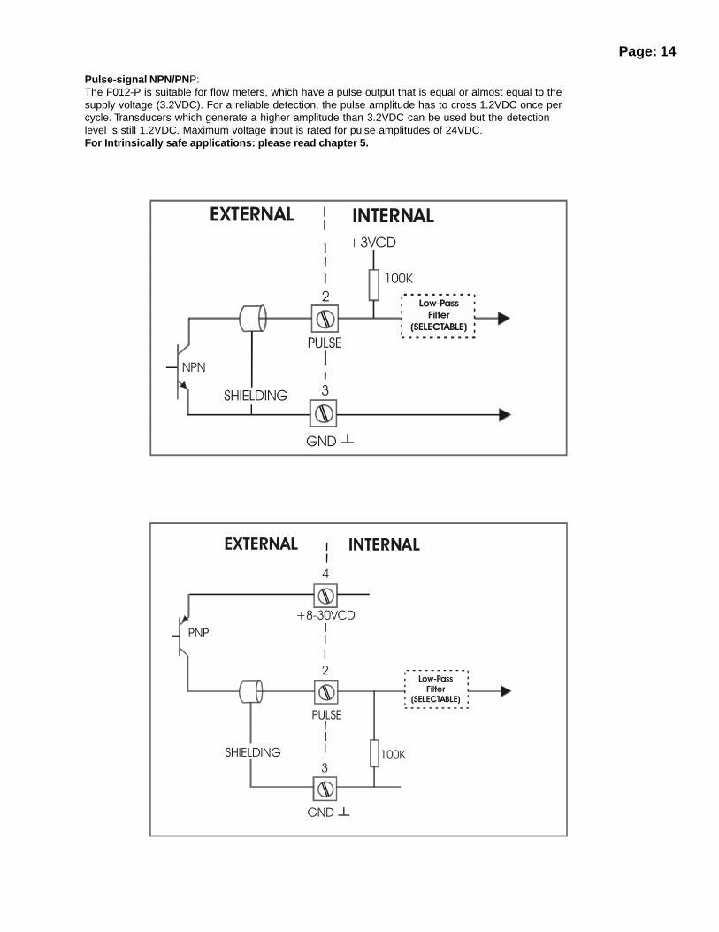
Pulse-signal NPN/PNP:The F012-P is suitable for flow meters, which have a pulse output that is equal or almost equal to thesupply voltage (3.2VDC). For a reliable detection, the pulse amplitude has to cross 1.2VDC once percycle. Transducers which generate a higher amplitude than 3.2VDC can be used but the detectionlevel is still 1.2VDC. Maximum voltage input is rated for pulse amplitudes of 24VDC.For Intrinsically safe applications: please read chapter 5.
��������� �������
�����
�������
�
�
����
����
���
��
��������
��� �
������������
�
��������� �������
�����
�������
�
�
�������
����
��
��
��������
��� �������������
�
�

Page: 15
Reed-switch:The F012-P is suitable f or flow meters, which have a reed-switch. To avoid pulse bounce from thereed-switch, it is advised to select REED LP - low-pass filter (setting 51).For Intrinsically safe applications: please read chapter 5.
NAMUR-signal:The signal input is according DIN19 234. Please notice that an external power supply is required.Maximum voltage input is 10VDC for NAMUR-type input.For Intrinsically safe applications: please read chapter 5.
Terminal 4 and 5; external power supply 8-30V DC:Connect an external power-supply of maximum 30V DC to these terminals. Connect the “-” to terminal5 and the “+” to terminal 4. The out -going voltage from the battery (option) is blocked automatically assoon as a higher voltage as 3.2 V DC is connected: it won’t damage the battery.
��������� �������
�����
�������
�� ���
��
�
�
�
��������
��� �
������������
�����
�����
��������� �������
�����
�������
���� ���
��
�
�
�
����
����
�����
�
�
�

Page: 16
5. INTRINSIC SAFETY CONNECTIONS
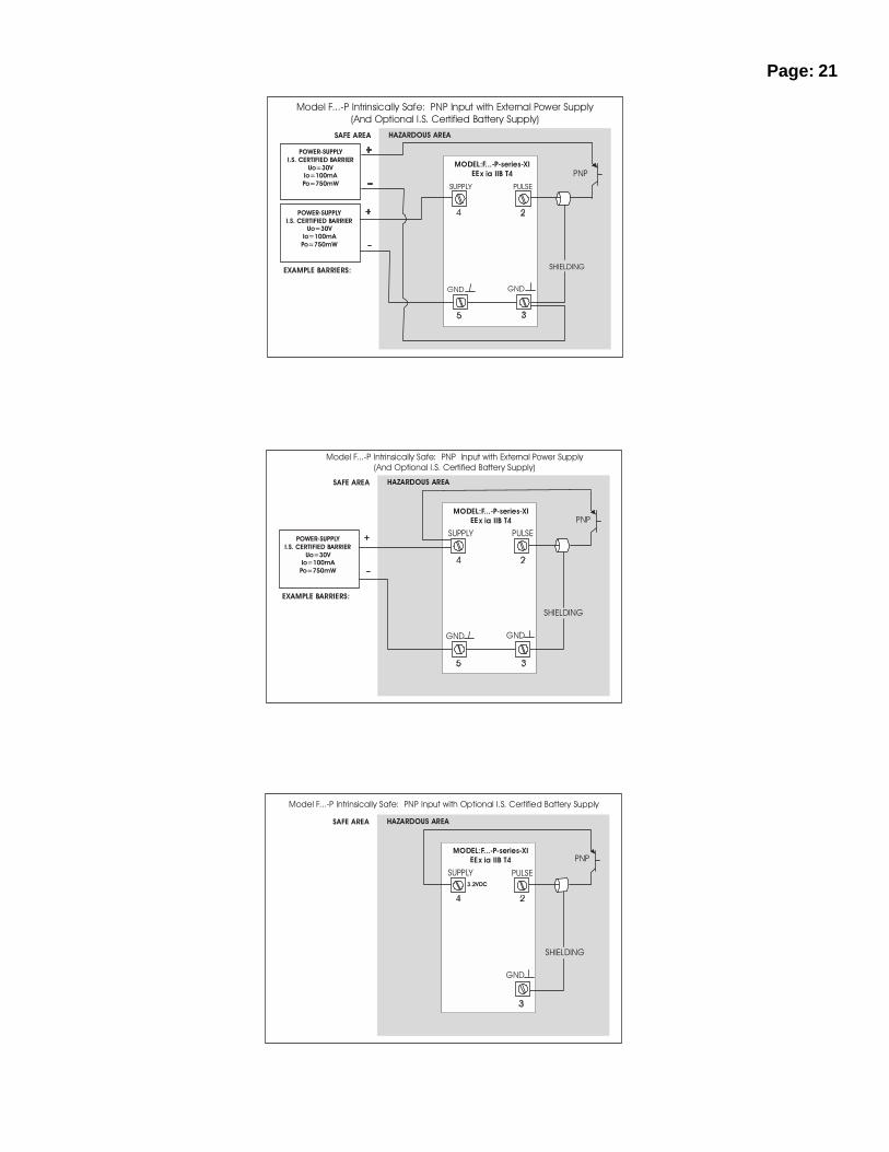
The F012-P can be installed in hazardous area when option XI for intrinsically safe has been supplied.In most applications, the classification for the F012-P-XI is EEx ia IIB T4 where a maximum of twobarriers can be connected to the unit. However, the F012-P-XI can be used in gas group Capplications according EEx ia IIC T4 when no external barriers are connected to the unit.Please study following pages with wiring diagrams per signal type for coil, NPN, PNP, reed-switch andNamur sensors.
When installing the F012-P-XI in hazardous areas, the wiring and installation must comply withappropriate installation standards.
COIL INPUT CIRCUIT: TERMINALS 1 (COIL), 2 (SIGNAL) AND 3 (GND): :In type of explosion protection intrinsic safety EEx ia IIB T4, only for connection to a certifiedintrinsically safe circuit, with following maximum values:
Ui = 30V DCIi = 100mAPi = 0.75W
the effective internal capacitance and inductance are negligibly small.
COIL INPUT CIRCUIT: TERMINALS 1 (COIL), 2 (SIGNAL) AND 3 (GND):In type of explosion protection intrinsic safety EEx ia IIC T4 or EExia IIB T4, only for connection to acertified intrinsically safe circuit, with following maximum values:
Uo = 5.1VIo = 5.2mAPo = 27mW
maximum allowed external capacitance Co and maximum allowed external inductance Lo dependingon gas group, in accordance with following table:
NAMUR INPUT CIRCUIT: TERMINALS 2 (SIGNAL) AND 3 (GND):In type of explosion protection intrinsic safety EEx ia IIB T4, only for connection to a certifiedintrinsically safe circuit, with following maximum values:
Ui = 30V DCIi = 100mAPi = 0.75W
the effective internal capacitance and inductance are negligibly small.
PNP INPUT CIRCUIT: TERMINALS 2 (SIGNAL) AND 3 (GND): :In type of explosion protection intrinsic safety EEx ia IIB T4, only for connection to a certifiedintrinsically safe circuit, with following maximum values:
Ui = 30V DCIi = 100mAPi = 0.75W
the effective internal capacitance and inductance are negligibly small.
PNP INPUT CIRCUIT: TERMINALS 2 (SIGNAL) AND 4 (SUPPLY):In type of explosion protection intrinsic safety EEx ia IIC T4 or EEx ia IIB T4, only for connection to acertified intrinsically safe circuit, with following maximum values:
Uo = 5.1VIo = 5.2mAPo = 27mW
maximum allowed external capacitance Co and maximum allowed external inductance Lo dependingon gas group, in accordance with following table:
Lo <= 1H 1HC o <= 1000uF 88uF
IIB IIC
Lo <= 1H 1HC o <= 1000uF 88uF
IIB IIC
Page: 17
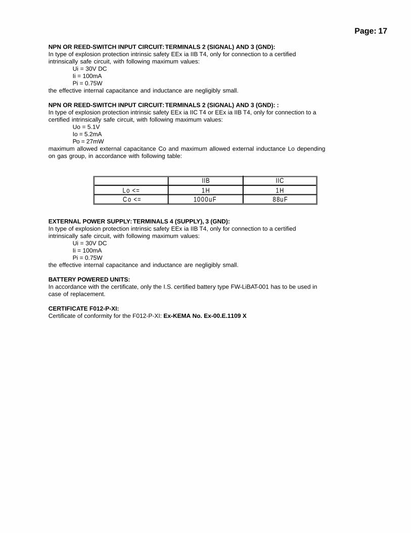
NPN OR REED-SWITCH INPUT CIRCUIT: TERMINALS 2 (SIGNAL) AND 3 (GND):In type of explosion protection intrinsic safety EEx ia IIB T4, only for connection to a certifiedintrinsically safe circuit, with following maximum values:
Ui = 30V DCIi = 100mAPi = 0.75W
the effective internal capacitance and inductance are negligibly small.
NPN OR REED-SWITCH INPUT CIRCUIT: TERMINALS 2 (SIGNAL) AND 3 (GND): :In type of explosion protection intrinsic safety EEx ia IIC T4 or EEx ia IIB T4, only for connection to acertified intrinsically safe circuit, with following maximum values:
Uo = 5.1VIo = 5.2mAPo = 27mW
maximum allowed external capacitance Co and maximum allowed external inductance Lo dependingon gas group, in accordance with following table:
EXTERNAL POWER SUPPLY: TERMINALS 4 (SUPPLY), 3 (GND):In type of explosion protection intrinsic safety EEx ia IIB T4, only for connection to a certifiedintrinsically safe circuit, with following maximum values:
Ui = 30V DCIi = 100mAPi = 0.75W
the effective internal capacitance and inductance are negligibly small.
BATTERY POWERED UNITS:In accordance with the certificate, only the I.S. certified battery type FW-LiBAT-001 has to be used incase of replacement.
CERTIFICATE F012-P-XI:Certificate of conformity for the F012-P-XI: Ex-KEMA No. Ex-00.E.1109 X
Lo <= 1H 1HC o <= 1000uF 88uF
IIB IIC

������������ �����
�
��������� ��������������
���������������
���������������������������� �!�"��#������$%��&��'�()���������&��� %$$��
Page: 18
������������ �����
�
����������������
�
�����
��������
!
�����
���
"
�
���
�����
���� ������
������ �������� ��
������
��������
��������
�
��������� ��������������
����
���������������
��������������������������� �!�"��#������$%��&��'�()���������&��� %$$��
�*���+$��������� ��#����!����,������� %$$��

������������ �����
���������������
����������������
�-. (
/�(.0�12
210�210�
-��.3
���� ������
������ �������� ��
������
��������
��������
�
��������� ��������������
���� ����������
������ �������� ��
������
��������
��������
�
1*�-4
�4+5���63
(1 +4
��������������������������� �!�"�1��%����$%��&��'�()���������&��� %$$���*���+$��������� ��#����!����,������� %$$��
������������ �����
���������������
�-. (
/�(.0�12
210�210�
-��.3
��������� ��������������
����������������
���� ����������
������ �������� ��
������
��������
��������
�
�� ��
����� ���
������
��������������������������� �!�"��1��%����$%��&��'�+$��������� ��#����!����,������� %$$���
�+��()���������&��� %$$��
Page: 19

������������ ������
7
�-. (
/�(.0�12
�
210�
�
210�
��������� ��������������
�
� �
���
������
���������������
������
��������������������������� �!�"��1�184���� &���'����$%��&��'�+$������
��� ��#����!����,������� %$$��
������������ ������
����������������
7
�-. (
/�(.0�12
�
210�
�
�
210�
-��.3
��������� ��������������
���������������
���
��
����
������
���������� ������
������ �������� ��
������
��������
��������
�
��������������������������� �!�"��1�184���� &���'���$%��&��'�()���������&��� %$$��
�*���+$��������� ��#����!����,������� %$$��
Page: 20
�������� � ������ ��
�������������
������� ������� �����
�������������
�����������
� � ������������������
������
��������
��������
�
�����
��������
������
������
��
��� !�"���#���$%&'$(')*!!+��*, -�������$./%�0'%1��2% &$*!���0 &��/..!+
�3$���.%'�$*!������� &%',' ��4*%% &+��/..!+
�������� � ������ ��
�������������
�������������
����
������ �
� ��� ��
����
����������
� � ������������������
������
��������
��������
�
������� ������� �����
�����������
� � ������������������
������
��������
��������
�
��
��������������������������� �!�"���1����$%��&��'�()���������&��� %$$��
�*���+$��������� ��#����!����,������� %$$��
�������� � ������ ��
�������������
������� ������� �����
������
�����
��������
���
������
��
��� !�"���#���$%&'$(')*!!+��*, -������$./%�0'%1��.%'�$*!������� &%',' ��4*%% &+��/..!+
Page: 21

Page: 22
6. MAINTENANCE
6.1. GENERAL DIRECTIONS
• Authorized technicians must carry out installation, use, maintenance and de-mountingof this equipment only.
• Take good notice of the “Safety rules and precautionary measures” in the front ofthis manual.
The rate/totaliser does not require special maintenance unless it is used in low-temperatureapplications and/or surroundings with high humidity (above 90% annual mean). It is customer’sresponsibility to take all precautions to dehumidify the internal atmosphere of the F012-P in such away that no condensation will take place, for example by placing dry silica gel in the casing just beforeclosing it. Furthermore, is required to replace or dry the silica gel from time to time as advised by the silicagel supplier.
Battery life-time:It is influenced by several issues such as:• Display update: see setting 41.• Low temperatures; the available power will be less due to battery chemistry.• It is advised to disable unused functions.
Check periodic:• The condition of the casing, cable glands and front panel.• The wiring of the several components on reliability and aging symptoms.• The process accuracy. As a result of wear and tear, re-calibration of the flow meter might be
necessary. Do adapt the actual K-factors.• The indication for low-battery.• Clean the casing with soap-water; don’t use any abrasive solvents as these might damage the
ABS or coating.

Page: 23
APPENDIX A: TECHNICAL SPECIFICATION F012-P
GENERAL
Display: High intensity reflective alphanumeric LCD, UV-resistant.Digits: Seven 17mm (0.67") and eleven 8mm (0.31"). Various symbols and
measuring units.
Refresh rate: Selectable via menu: 8 times/sec - 30 sec’s.Case: ABS - IP65 / NEMA 4.Mounting: Standard panel-mount case.Dimensions: 130 x 114 x 50mm (5.1" x 4.5" x 1.97") - LxHxD.Panel cut-out: 115 x 96mm (4.53" x 3.78") LxH.Window: Polycarbonate window.Sealing: EPDM and PE.Control keys Three industrial micro-switch keys. UV-resistant polyester keypad.Option HD: ABS IP65 / NEMA 4 wall-mount casing.Dimensions: 130 x 114 x 71mm (5.1" x 4.5" x 2.8") - LxHxD.Option HA: Aluminium IP67 / NEMA 4 wall-mount, sensor head-mount.
Dimensions130 x 114 x 58mm (5.1" x 4.5" x 2.3") - LxHxD.Operating temperature: -30°C to +80°C (-22°F to +178°F).Power requirements: 8-30V DC supply can be connected to power the unit.Option PA: Internal Lithium battery 3.2V DC: average lifetime seven years dependent
upon settings and sensor type.Sensor excitation: same voltage as offered to power the unit.Terminal connections: Removable plug strip. Wire max. 1.5mm2.Data protection: EEPROM backup of all setting. Backup total and accumulated total every
minute.Hazardous area: (optional) Cenelec approval ref: EEx ia IIB/IIC T4. CSA certification is
pending. Maximum ambient 70°C (158°F). Option XI.Environment CE: EMC compliant ref: EN50081 and EN50082.Pulse inputs: Type P: Coil/sine wave (minimum 20mVpp or 80mVpp - sensitivity
selectable), NPN/PNP, open collector, reed-switch, Namur.Frequency: Minimum 0 Hz - maximum 10 KHz for total and flow rate. Max frequency
depends on signal type and internal low-pass filter.Reed switch with low-pass filter = max. 200 Hz.
Low-pass filter: Available for all pulse signals.Selection main function: Total or flow rate will be displayed with 17mm digits.
OPERATOR FUNCTIONS
General: The Operator has three functions available:- TOTAL and flow rate are displayed.- TOTAL can be reset by pressing CLEAR-key twice.- After pressing SELECT, accumulated TOTAL will be displayed.
TOTAL: 17mm character-size - 7 digits.Measuring units: L, m3, GAL, USGAL, KG, lb, bbl, no unit.K-factor: 7 positions 0.000010 - 9,999,999.Number of decimals: max. three. TOTAL is reset able.
Accumulated total: 8mm character-size - 11 digits. Acc. total is not reset able.Uses same K-factor, unit and decimals as TOTAL.
FLOWRATE: 8mm character-size or 17mm character-size - 5 digits.Settings independent of TOTAL.Measuring units: mL, L, m3, Gallons, KG, ton, lb, bl, cf, rnd, no unit.Time units: second, minute, hour, day.K-factor: 7 positions 0.000010 - 9,999,999.Number of decimals: max. one.

Page: 24
APPENDIX B: PROBLEM SOLVING
In this appendix, several problems are included that can occur when the rate/totaliser is going to beinstalled or while it is in operation.
Flow meter does not generate pulses:Check:- Flow meter, wiring and connection of terminal connectors (par. 4.4.4.),
Flow meter does generate “too many pulses”:Check:- Settings for Total and Flow rate: SETUP 11-14 and 21-27,- Proper grounding of the F012-P - par. 4.4.4.- Use screened wire for flow meter signals and connect screen to terminal 9.- Check the linearization function.
Flow rate displays “0 / zero” while there is flow (total is counting):Check:- SETUP 22 / 25: are the K-factor and time unit correct?- SETUP 26 / 27: The unit has to count the number of pulses according to setup 26 within the time
according to setup 27. Make sure that 27 is set like 10.0 seconds e.g. : the result is that the unithas at least 10 seconds time to measure the number of pulses according to setup 26.
The password is unknown:If the password is not 1234, there is only one possibility left: call your supplier.
ALARMWhen the alarm flag starts to blink an internal alarm condition has occurred. Press the “select button”several times to display the 5-digit error code. The codes are:
0001: irrecoverable display -data error: data on the display might be corrupted.0002: irrecoverable data-storage error: the programming cycle might have gone wrong: check
programmed values.0003: error 1 and error 2 occurred simultaneously
The alarm condition will most certainly be handled internally and if all mentioned values still appearright, no intervention of the operator is needed. In case the alarm occurs more often or stays active fora longer time, please contact your supplier.

Page: 25
INDEX:
accumulated Total 4actual settings 28Battery powered 12; 17CLEAR � 3Clear Total 4Coil-signal 13; 16Configuration 5Dimensions 11display update 9flowmeter signal 9Flowmeter input 13; 16flowrate calculation 8 cut-off time 8 decimals 8 decimals k-f actor 8 display 17mm digits 8 k-factor 8 measuring unit 8 time unit 8Installation 11Intrinsic safety 16IP classification 11keys 3loop powered 15low-battery 4Low-battery alarm 4main-function 5maintenance 22model 10NAMUR signal 12; 15; 16Notes 26operational mode 9Operator level 4password 10; 24Power management 9Problem solving 24PROG / ENTER 3PROG-procedure 7Pulse-signal NPN/PNP 14; 16; 17rate/Total 4Reed-switch: 15; 17SELECT � 3serial number 10SETUP-level 5shelf -mode 9subfunction 5tagnumber 10Technical specification 23terminal connectors 13total decimals 7 decimals k-factor 7 k-factor 7 measuring unit 7version software 10

Page:26
LIST OF ACTUAL SETTINGS F012-P
SETTING: STANDARD DATE: DATE:
1 - TOTAL:11 unit L
12 decim als 0000000
13 K -factor 0000001
14 decim als K-factor 0
2 - FLOW RATE:21 unit L
22 tim e unit /m in
23 decim als 0000000
24 K -factor 0000001
25 decim als K-factor 0
26 calcu lation / pulses 10
27 cut-o ff tim e 30.0 sec.
3 - DISPLAY31 function to tal
4 - POW ER MAN.41 LC D-new 1 sec.
42 m ode operational
5 - FLOW METER51 signal type coil-lo
6 - OTHERS64 passw ord 0000
65 tag num ber 0000000