operation manual...keep your machine in proper working condition.unauthorized modifications to the...
TRANSCRIPT

OPERATION MANUAL COMPACT TRACTOR
504G3
WWW.KNEGT-INTERNATIONAL.COM

504G3 SERIES TRACTOR
OPERATION MANUAL
Please Read and Save This Manual
KNEGT QUALITY TRACTOR EUROPE
2018.09

504G3 SERIES TRACTOR OPERATION MANUAL
FOREWORD
These series model KNEGT 504G3 is a series newly developed
product of Knegt Quality Tractors Europe and are powered with
the four-cylinder diesel engines that have the features of ample
output,less vibration and low noise as well.
Model 504G3 tractors are of single-function type for using in both
paddy and dry fields. The designers have cogitated on some
components, which can be selected for assembling in order to
meet users’ various needs.
In order to fit in with the international market, some
components for perfecting the tractor have been designed and
developed, such as the hydraulic power steering, hydraulic PTO
clutch,two-speed PTO and so on. All of these have improved the
performance of the tractor greatly.
These tractors have the advantages of economic
fuel consumption, easy operation, harmonious appearance,
compact construction and easy maintenance. This tractor series is
only used for conventional agriculture and domestic purposes
and similar operations, with the suitable agricultural
machinery, for other operating contrary to the intended use of
the tractor, such as shall not be used for front-end loader and
forestry application and spraying. This tractor can only be
operated by the personnel who is familiar with tractor’s
characteristics and have the knowledge of relevant safe
manipulation, the same for maintenance and repair. This tractor
can not be operated by children and agedness and other personnel
who is not to conformity with the provisions.
1

504G3 SERIES TRACTOR OPERATION MANUAL
Read the Operation Manual carefully before starting, using,
maintaining, refueling or making other service interventions on
the tractor. Comply strictly with the safety regulation and follow
the suggested precautions in order to safeguard yourselves. If
you are unsure about anything, ask your East Wind dealer or
employer. Do not guess, others and you could be killed or
seriously injured.
Many warming sign alerts such as ‘ ’ on the tractor and
operation manual. This warning sign alerts you about important
messages involving your safety. Read these safety rules
attentively and strictly follow suggested precautions to avoid
any potential danger and ensure your health and personal
safety.
In order to meet users’ needs continuously, this tractor is subject
to improvement without notice. It may happen to the fact that there
are some differences between the manual/illustrated parts catalogue
and the structure of the real tractors. So the dealers or users are
requested to provide PIN number and manufacturing date of the
tractor while placing order for spare parts.
Thank you for purchasing the KNEGT Brand Tractor and
cordially welcome your advice, suggestions and comments on
our product so that we can make improvements timely in future.
Knegt Quality Tractor Europe
September 2018
2
504G3 SERIES TRACTOR OPERATION MANUAL
3
CONTENT
Chapter 1 Safety Precautions ............................................................ 5
1.1 Safety Instructions .................................................................................................. 51.2 Safety symbols ..................................................................................................... 121.3 Measures for emergency ...................................................................................... 16
Chapter 2 Technical Specifications ................................................. 17
2.1 Tractor characteristic ............................................................................................ 172.2 Identifying your machine ..................................................................................... 172.3 Technical specification of the tractor ................................................................... 19
Chapter 3 Running-in of the tractor .............................................. 27
3.1 Preparation before Running-in of the tractor ....................................................... 273.2 Running-in the engine without load ..................................................................... 273.3 Running in of hydraulic hitch system .................................................................. 283.4 Running-in of hydraulic steering system ............................................................. 283.5 Running in of PTO ............................................................................................... 283.6 Running in of the Tractor ..................................................................................... 293.7 Maintenance after running-in ............................................................................... 30
Chapter 4 Operating tractor ........................................................... 32
4.1 Instrument and Controls ....................................................................................... 324.3 Using the Tractor implents ................................................................................... 524.4 The use of electrical systems ................................................................................ 60
Chapter 5 Maintenance ................................................................... 63
5.1 Oil and lubricants ................................................................................................. 635.2 Periodic Service ................................................................................................... 645.3 Transporting the Machine .................................................................................... 665.4 Storage .................................................................................................................. 68
Chapter 6 Adjustment of the tractor .............................................. 70
6.1 Adjustment of the engine ..................................................................................... 706.2 Adjustment of the clutch ...................................................................................... 706.3 Adjustment of the Brake ....................................................................................... 71
6.4 Adjustment of the Chassis ..................................................................................... 72
6.5 Adjustment of the Front Axle (4WD) .................................................................... 74
504G3 SERIES TRACTOR OPERATION MANUAL
4
6.6 Adjustment of the toe-in ........................................................................................ 78
6.7 Adjustment of the wheel track ............................................................................... 78
6.8 Adjustment of rockshaft system ............................................................................ 79
Chapter 7 Troubleshooting.............................................................. 81
7.1 Clutch ................................................................................................................... 817.2 Gearbox ................................................................................................................ 827.3 Rear axle ............................................................................................................... 827.4 Braking system ..................................................................................................... 837.5 Front driven axle (4WD) ...................................................................................... 837.6 Walking system .................................................................................................... 847.7 Hydraulic steering system .................................................................................... 847.8 PTO ...................................................................................................................... 857.9 Hydraulic Hitch System ....................................................................................... 867.10 Electrical system ................................................................................................ 87
7.11 Heating system .................................................................................................... 88
Chapter 8 Appendix ......................................................................... 89
Appendix 1 Standards and Regulations ..................................................................... 89Appendix 2 Tightening Torque Table of Main Bolts and Nuts .................................. 90Appendix 3 Scheme of the electric system ................................................................ 91Appendix 4 List of damageable parts ......................................................................... 92Appendix 5 List of Attached Tools ............................................................................ 92Appendix 6 Mechanical couplings ............................................................................. 93Appendix 7 E-MARK certificate ............................................................................... 99Appendix 8 Optional Accessories ............................................................................ 106Appendix 9 Application Packing List ...................................................................... 106
504G3 SERIES TRACTOR OPERATION MANUAL
5
Chapter 1 Safety Precautions
1.1 Safety Instructions
1.1.1 Safety first
The respect of the rules for tractor use, maintenance and repair given in this manual is
an essential element for the correct use of the tractors as envisioned by the
manufacturer.
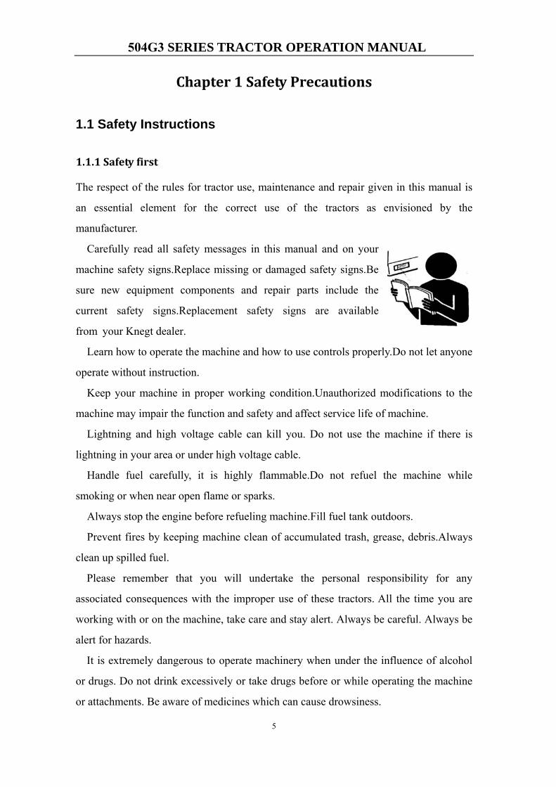
Carefully read all safety messages in this manual and on your
machine safety signs.Replace missing or damaged safety signs.Be
sure new equipment components and repair parts include the
current safety signs.Replacement safety signs are available
from your Knegt dealer.
Learn how to operate the machine and how to use controls properly.Do not let anyone
operate without instruction.
Keep your machine in proper working condition.Unauthorized modifications to the
machine may impair the function and safety and affect service life of machine.
Lightning and high voltage cable can kill you. Do not use the machine if there is
lightning in your area or under high voltage cable.
Handle fuel carefully, it is highly flammable.Do not refuel the machine while
smoking or when near open flame or sparks.
Always stop the engine before refueling machine.Fill fuel tank outdoors.
Prevent fires by keeping machine clean of accumulated trash, grease, debris.Always
clean up spilled fuel.
Please remember that you will undertake the personal responsibility for any
associated consequences with the improper use of these tractors. All the time you are
working with or on the machine, take care and stay alert. Always be careful. Always be
alert for hazards.
It is extremely dangerous to operate machinery when under the influence of alcohol
or drugs. Do not drink excessively or take drugs before or while operating the machine
or attachments. Be aware of medicines which can cause drowsiness.
504G3 SERIES TRACTOR OPERATION MANUAL
6
Do not attempt to operate the machine if you are feeling unwell. By doing so you
could be a danger to yourself and those you work with.
You can reduce the risk of damage to the machine or your body by following the
instructions in this manual.
If you do not understand any parts of this manual and need assistant, contact your
Knegt dealer.
This machine is manufactured in compliance with legislative and other requirements.
It should not be altered in any way which could affect or invalidate any of these
requirements. For advice consult your Knegt Distributor.
Use only the Knegt approved attachments that are specified for your
machine. Operating with nonspecified attachments can overload the
machine, causing possible damage and machine instability which could result in
injury to yourself or others. The use of non-approved attachments could invalidate
your warranty.
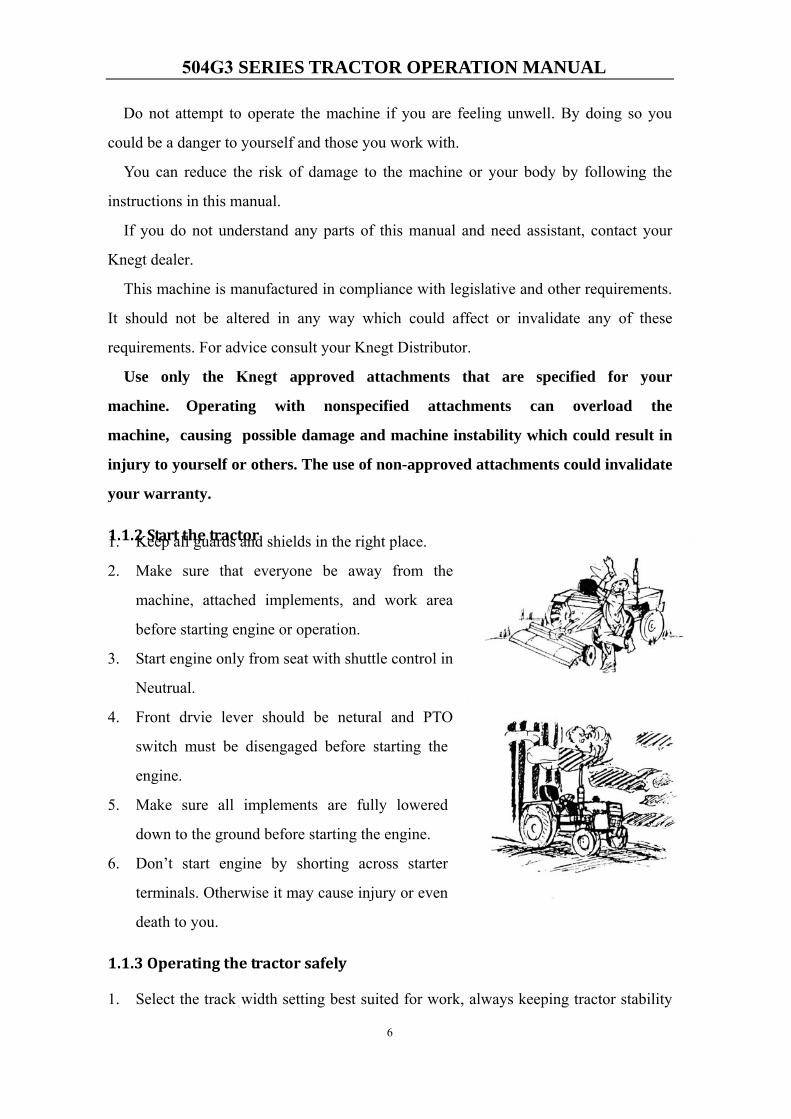
1.1.2 Start the tractor 1. Keep all guards and shields in the right place.
2. Make sure that everyone be away from the
machine, attached implements, and work area
before starting engine or operation.
3. Start engine only from seat with shuttle control in
Neutrual.
4. Front drvie lever should be netural and PTO
switch must be disengaged before starting the
engine.
5. Make sure all implements are fully lowered
down to the ground before starting the engine.
6. Don’t start engine by shorting across starter
terminals. Otherwise it may cause injury or even
death to you.
1.1.3 Operating the tractor safely
1. Select the track width setting best suited for work, always keeping tractor stability
504G3 SERIES TRACTOR OPERATION MANUAL
7
in mind.
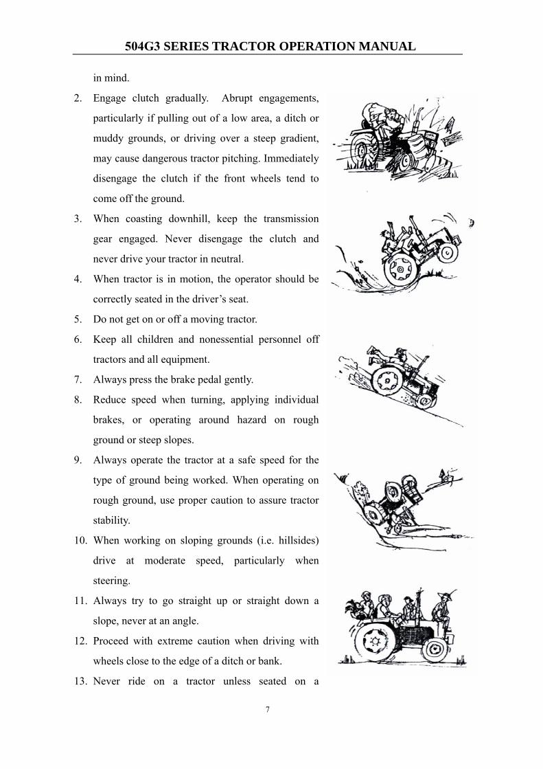
2. Engage clutch gradually. Abrupt engagements,
particularly if pulling out of a low area, a ditch or
muddy grounds, or driving over a steep gradient,
may cause dangerous tractor pitching. Immediately
disengage the clutch if the front wheels tend to
come off the ground.
3. When coasting downhill, keep the transmission
gear engaged. Never disengage the clutch and
never drive your tractor in neutral.
4. When tractor is in motion, the operator should be
correctly seated in the driver’s seat.
5. Do not get on or off a moving tractor.
6. Keep all children and nonessential personnel off
tractors and all equipment.
7. Always press the brake pedal gently.
8. Reduce speed when turning, applying individual
brakes, or operating around hazard on rough
ground or steep slopes.
9. Always operate the tractor at a safe speed for the
type of ground being worked. When operating on
rough ground, use proper caution to assure tractor
stability.
10. When working on sloping grounds (i.e. hillsides)
drive at moderate speed, particularly when
steering.
11. Always try to go straight up or straight down a
slope, never at an angle.
12. Proceed with extreme caution when driving with
wheels close to the edge of a ditch or bank.
13. Never ride on a tractor unless seated on a
504G3 SERIES TRACTOR OPERATION MANUAL
8
Knegt approved seat with seat belt.
14. When driving on public roads, be sure to respect traffic rules and regulations.
15. Do not rest your feet on the brake and the clutch pedals.
16. When driving on roads latch the brake pedals together by using the latch plate,
braking with the pedals unlatched may cause side skidding of the tractor. Try to
avoid overworking the brakes.
1.1.4 Towing loads
1. To assure tractor stability while working, correctly adjust the towing attachments
(depending on the towed trailer or drawn implement).
2. Be careful when towing and stopping heavy loads.Stopping distance increase with
speed and weight of towed loads, and on slopes.Towed loads with or without
brakes that are too heavy for the tractors or are towed too fast can cause loss of
control.
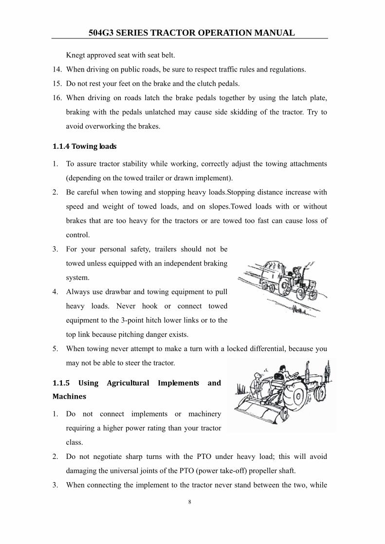
3. For your personal safety, trailers should not be
towed unless equipped with an independent braking
system.
4. Always use drawbar and towing equipment to pull
heavy loads. Never hook or connect towed
equipment to the 3-point hitch lower links or to the
top link because pitching danger exists.
5. When towing never attempt to make a turn with a locked differential, because you
may not be able to steer the tractor.
1.1.5 Using Agricultural Implements and
Machines
1. Do not connect implements or machinery
requiring a higher power rating than your tractor
class.
2. Do not negotiate sharp turns with the PTO under heavy load; this will avoid
damaging the universal joints of the PTO (power take-off) propeller shaft.
3. When connecting the implement to the tractor never stand between the two, while
504G3 SERIES TRACTOR OPERATION MANUAL
9
the tractor is being backed up.
4. Never activate the power take-off (PTO) when it is connected to a moving
implement, without previously making sure that no one is within operating range of
this implement.
5. You can be injured if you use faulty lifting equipment. Make sure that lifting
equipment is in good condition. Make sure that lifting tackle complies with all local
regulations and is suitable for the job. Make sure that lifting equipment is strong
enough for the job. Raised equipment can fall and injure you. Do not walk or work
under raised equipment unless safely supported.
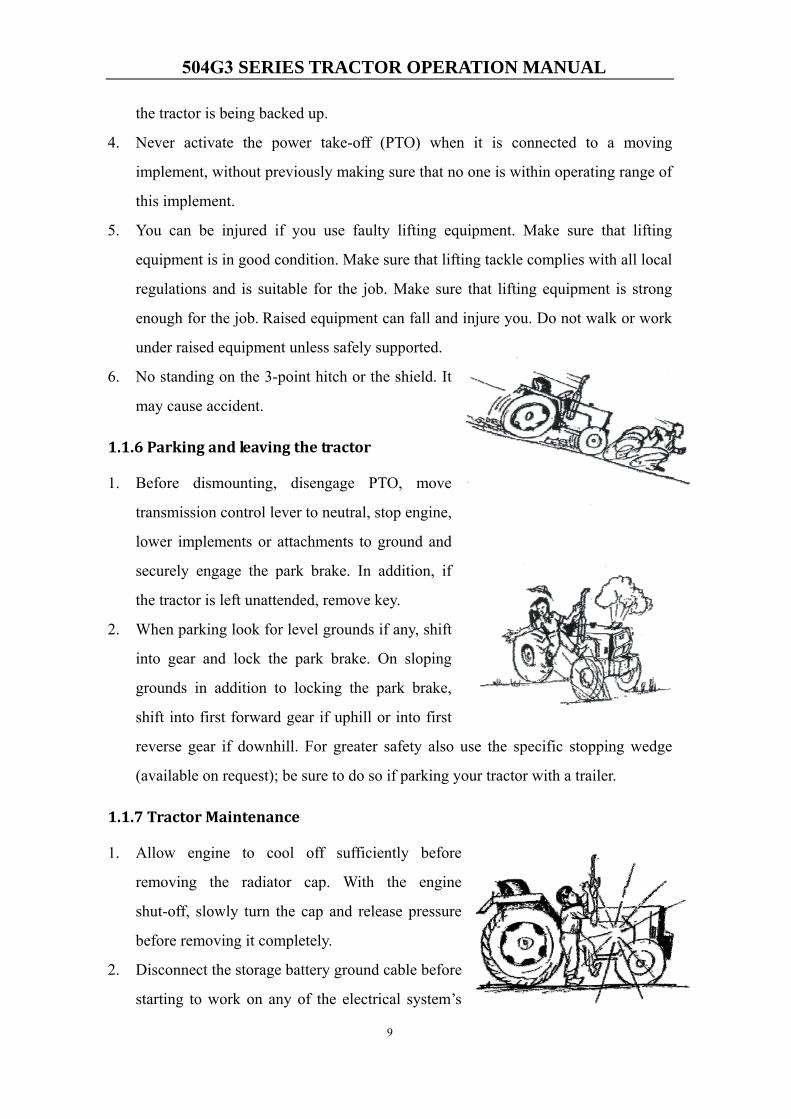
6. No standing on the 3-point hitch or the shield. It
may cause accident.
1.1.6 Parking and leaving the tractor
1. Before dismounting, disengage PTO, move
transmission control lever to neutral, stop engine,
lower implements or attachments to ground and
securely engage the park brake. In addition, if
the tractor is left unattended, remove key.
2. When parking look for level grounds if any, shift
into gear and lock the park brake. On sloping
grounds in addition to locking the park brake,
shift into first forward gear if uphill or into first
reverse gear if downhill. For greater safety also use the specific stopping wedge
(available on request); be sure to do so if parking your tractor with a trailer.
1.1.7 Tractor Maintenance
1. Allow engine to cool off sufficiently before
removing the radiator cap. With the engine
shut-off, slowly turn the cap and release pressure
before removing it completely.
2. Disconnect the storage battery ground cable before
starting to work on any of the electrical system’s
504G3 SERIES TRACTOR OPERATION MANUAL
10
parts or components.
3. Before disconnecting any hydraulic line or hose, make sure the system is
pressure-free.
4. Hydraulic oil escaping under pressure can cause serious personal injury. When
searching for or detecting oil leaks, make sure to use adequate safety protection
such as shields, goggles and gloves.
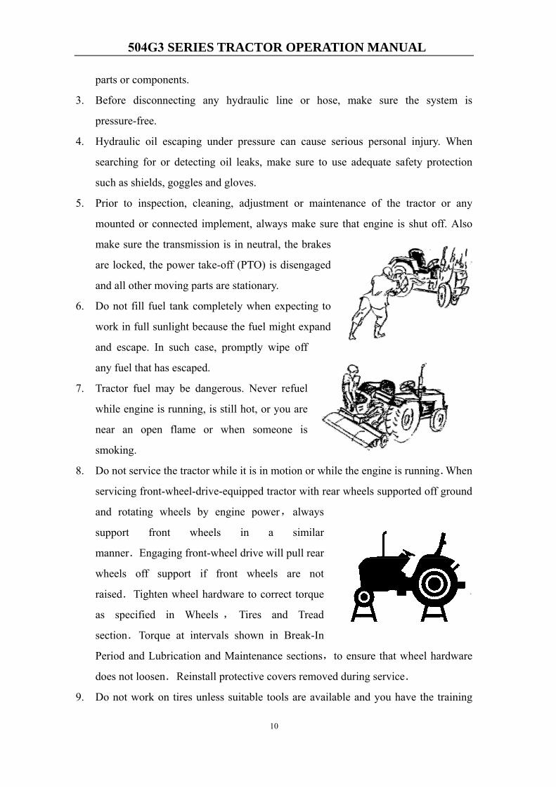
5. Prior to inspection, cleaning, adjustment or maintenance of the tractor or any
mounted or connected implement, always make sure that engine is shut off. Also
make sure the transmission is in neutral, the brakes
are locked, the power take-off (PTO) is disengaged
and all other moving parts are stationary.
6. Do not fill fuel tank completely when expecting to
work in full sunlight because the fuel might expand
and escape. In such case, promptly wipe off
any fuel that has escaped.
7. Tractor fuel may be dangerous. Never refuel
while engine is running, is still hot, or you are
near an open flame or when someone is
smoking.
8. Do not service the tractor while it is in motion or while the engine is running.When
servicing front-wheel-drive-equipped tractor with rear wheels supported off ground
and rotating wheels by engine power,always
support front wheels in a similar
manner.Engaging front-wheel drive will pull rear
wheels off support if front wheels are not
raised.Tighten wheel hardware to correct torque
as specified in Wheels , Tires and Tread
section.Torque at intervals shown in Break-In
Period and Lubrication and Maintenance sections,to ensure that wheel hardware
does not loosen.Reinstall protective covers removed during service.
9. Do not work on tires unless suitable tools are available and you have the training
504G3 SERIES TRACTOR OPERATION MANUAL
11
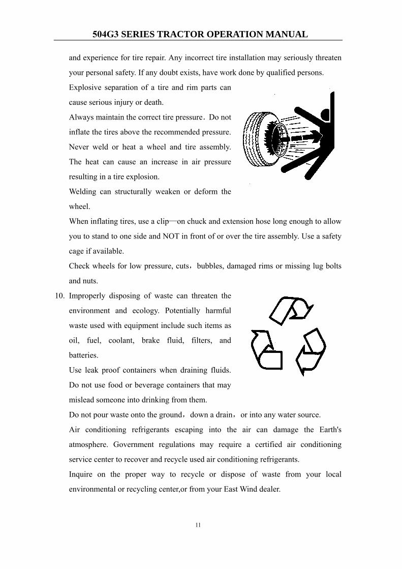
and experience for tire repair. Any incorrect tire installation may seriously threaten
your personal safety. If any doubt exists, have work done by qualified persons.
Explosive separation of a tire and rim parts can
cause serious injury or death.
Always maintain the correct tire pressure.Do not
inflate the tires above the recommended pressure.
Never weld or heat a wheel and tire assembly.
The heat can cause an increase in air pressure
resulting in a tire explosion.
Welding can structurally weaken or deform the
wheel.
When inflating tires, use a clip—on chuck and extension hose long enough to allow
you to stand to one side and NOT in front of or over the tire assembly. Use a safety
cage if available.
Check wheels for low pressure, cuts,bubbles, damaged rims or missing lug bolts
and nuts.
10. Improperly disposing of waste can threaten the
environment and ecology. Potentially harmful
waste used with equipment include such items as
oil, fuel, coolant, brake fluid, filters, and
batteries.
Use leak proof containers when draining fluids.
Do not use food or beverage containers that may
mislead someone into drinking from them.
Do not pour waste onto the ground,down a drain,or into any water source.
Air conditioning refrigerants escaping into the air can damage the Earth's
atmosphere. Government regulations may require a certified air conditioning
service center to recover and recycle used air conditioning refrigerants.
Inquire on the proper way to recycle or dispose of waste from your local
environmental or recycling center,or from your East Wind dealer.

504G3 SERIES TRACTOR OPERATION MANUAL
12
1.2 Safety symbols
No. Safety symbol Meaning Position
1 Keep away from rotating components when the mechine is working.
On the right side of the radiator
2
Don’t touch the hot surface until it’s cool enough, otherwise you may be damaged.
On the right side of the radiator,
near the muffler
3 Keep away from radiator. There may be hot fluids or steam
Above the radiator
4 If you want to operate Please Read the operators handbook。
On the PTO shield
5
Don’t jump out of the tractor when it turns over, it may cause worse result.
Keep the ROPS in the fully extended and locked position.
On the left side of Safety Frame
6 Please fasten your seat belt. Above the Panel

504G3 SERIES TRACTOR OPERATION MANUAL
13
7 Don’t add fuel, do maintenance and so on when the tractor is running.
On the right windshield
8 Power take-off actuator and/or rotational-speed selector position:disengaged
Beside the PTO operating
lever,on the fender
9 Power take-off actuator and/or rotational-speed selector position:540rpm
10 Power take-off actuator and/or rotational-speed selector position:1000rpm
11 Only ride on the operator’s seat. Or it may cause serious accident.
on the right fender
12 Lifting mechanism control: raised position.
on the fenders
13 Lifting mechanism control: lowered position.
on the fenders
14
Be clear of the mechine when it’s lifting implements or heavies. It may cause accidents.
On outside surface of the squab panel
15 Parking brake control, Stopping and parking the machine.
Beside the Handle brake
control lever,on the squab panel
504G3 SERIES TRACTOR OPERATION MANUAL
14
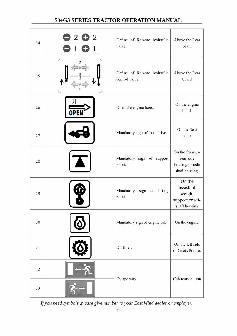
16 No standing on the 3-point hitch or the shield. It may cause accident.
On the outside surface of the squab panel
17 When you see this symbols, you should read Operators handbook.
On the Panel
18 Checking and adjusting the fluid level.
Near the oil filler
19 Do not use the differential lock at high speed or on the road.
Beside the differential pedal,on the
outside surface of the squab
panel
20 D
Filling the tank. On fuel tank
cap
21 Do not trample. Above the battery
22 Disconnect the battery before working on the machine.
Above the battery
23 Freeing a Mired Machine. On the right
outside surface of Safety Frame
504G3 SERIES TRACTOR OPERATION MANUAL
15
24 Define of Remote hydraulic valve.
Above the Rear beam
25 Define of Remote hydraulic control valve.
Above the Rear board
26 Open the engine hood. On the engine
hood.
27 Mandatory sign of front drive.
On the Seat plate.
28 Mandatory sign of support point.
On the frame,or rear axle
housing,or axle shaft housing.
29 Mandatory sign of lifting point.
On the assistant weight
support,or axle shaft housing
30 Mandatory sign of engine oil. On the engine.
31 Oil filler. On the left side of Safety Frame.
32
Escape way Cab rear column
33
If you need symbols ,please give number to your East Wind dealer or employer.
504G3 SERIES TRACTOR OPERATION MANUAL
16
1.3 Measures for emergency
1. When lost of steering control, slow down the tractor, engage the emergency brake,
and then shut down the engine.
2. If the engine shut down when going up the slope, step down the brake pedals
immediately, and engage the park brake to avoid slipping down along the slope.
Ignite the engine after that, and shift to a proper gear, then go up the slope with
smooth.
3. If the brake system fails, control the steering wheel, slow down the tractor or shift
to lower gear, and running the tractor in neutral, then shut down the engine in safe
place.
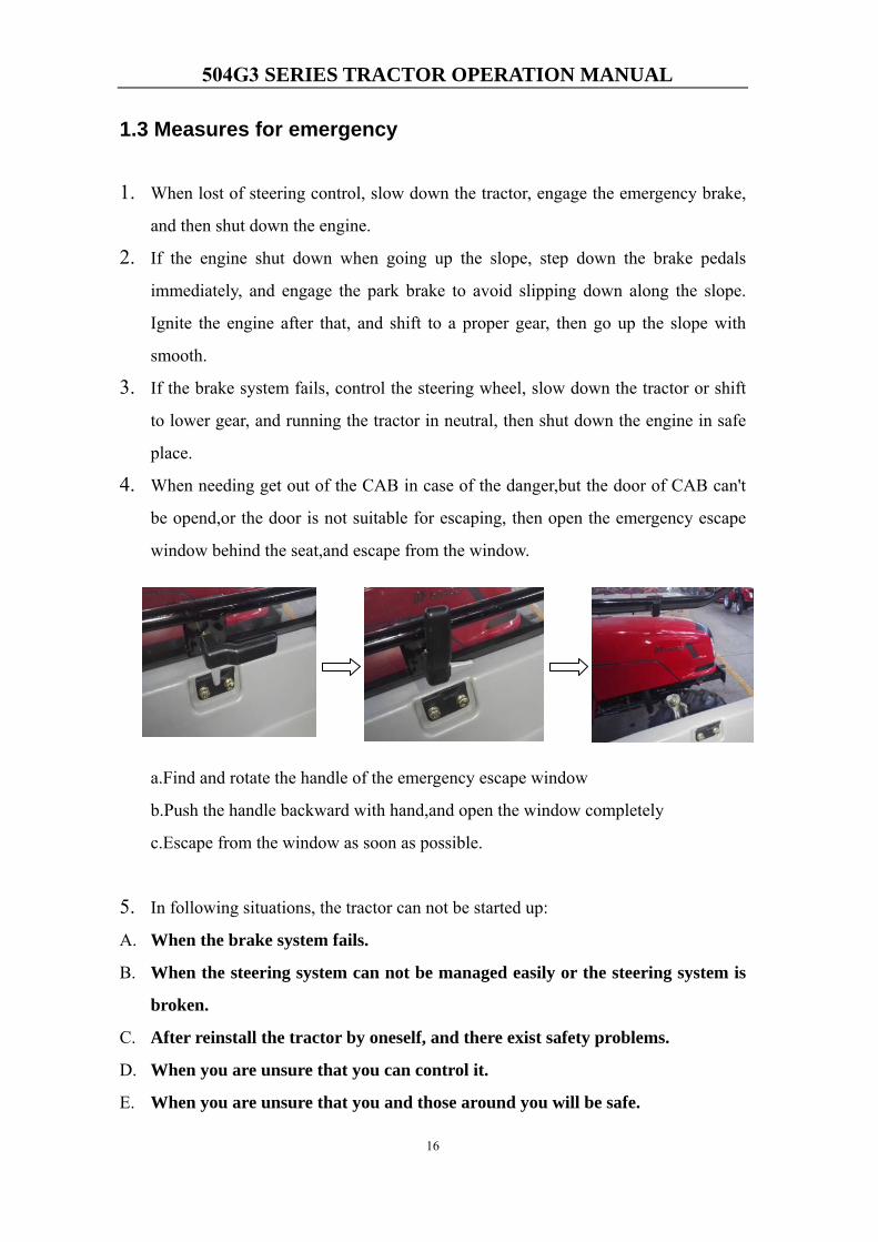
4. When needing get out of the CAB in case of the danger,but the door of CAB can't
be opend,or the door is not suitable for escaping, then open the emergency escape
window behind the seat,and escape from the window.
a.Find and rotate the handle of the emergency escape window
b.Push the handle backward with hand,and open the window completely
c.Escape from the window as soon as possible.
5. In following situations, the tractor can not be started up:
A. When the brake system fails.
B. When the steering system can not be managed easily or the steering system is
broken.
C. After reinstall the tractor by oneself, and there exist safety problems.
D. When you are unsure that you can control it.
E. When you are unsure that you and those around you will be safe.

504G3 SERIES TRACTOR OPERATION MANUAL
17
Chapter 2 Technical Specifications
2.1 Tractor characteristic
DF504G3 series tractor operator see table.
Table 2-1 Technical Specification
Tractor
Model Type
Engine Type of
hydraulic lift
system
Control of
clutch and
brake
ROPS/CABRated
Power
(Kw)
Rated
Speed
(rmp)
DF504G3 4WD 36 2400 independent Hang YES
2.2 Identifying your machine
2.2.1 Machine Identification Plate
Your machine has an identification
plate mounted on the front right hand
side of the machine. Information
contained on this plate includes
Category and speed index, VIN,
Technically permissible laden masses,
Technically permissible towable
masses, Manufacturer and Address.
The machine VIN and engine serial
numbers can help identify exactly the
type of equipment you have.

504G3 SERIES TRACTOR OPERATION MANUAL
18
2.2.2 Component Identification Plates
Engine Identification Plate Location
The engine identification plate is attached to the left hand side of the engine block. The information contained on this plate includes the engine model and serial number.
ROPS Certification Plate
Your machine is built to the ROPS
standard and has an identification
identification label is shown below.
Label fitted to the ROPS or cab.
Tractor Drawbar Or Clevis type Certification Plate
The Tractor drawbar or Clevis type on your machine is built to a standard and has an identification label fitted to the top of the trailer hitch. A typical identification label is shown below.
504G3 SERIES TRACTOR OPERATION MANUAL
19
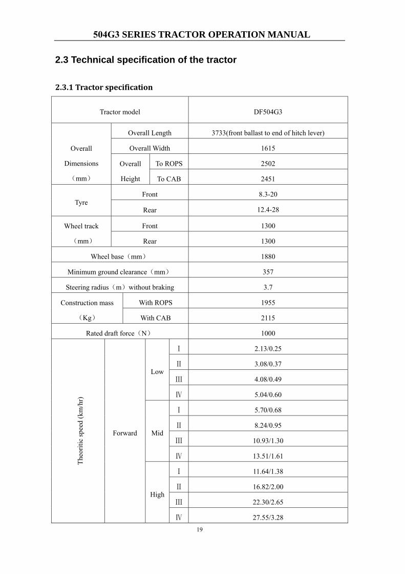
2.3 Technical specification of the tractor
2.3.1 Tractor specification
Tractor model DF504G3
Overall
Dimensions
(mm)
Overall Length 3733(front ballast to end of hitch lever)
Overall Width 1615
Overall
Height
To ROPS 2502
To CAB 2451
Tyre Front 8.3-20
Rear 12.4-28
Wheel track
(mm)
Front 1300
Rear 1300
Wheel base(mm) 1880
Minimum ground clearance(mm) 357
Steering radius(m)without braking 3.7
Construction mass
(Kg)
With ROPS 1955
With CAB 2115
Rated draft force(N) 1000
Theo
ritic
spee
d (k
m/h
r)
Forward
Low
Ⅰ 2.13/0.25
Ⅱ 3.08/0.37
Ⅲ 4.08/0.49
Ⅳ 5.04/0.60
Mid
Ⅰ 5.70/0.68
Ⅱ 8.24/0.95
Ⅲ 10.93/1.30
Ⅳ 13.51/1.61
High
Ⅰ 11.64/1.38
Ⅱ 16.82/2.00
Ⅲ 22.30/2.65
Ⅳ 27.55/3.28
504G3 SERIES TRACTOR OPERATION MANUAL
20
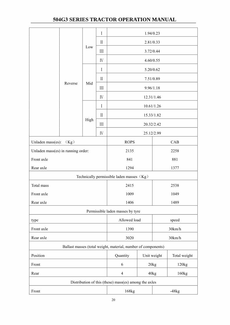
Reverse
Low
Ⅰ 1.94/0.23
Ⅱ 2.81/0.33
Ⅲ 3.72/0.44
Ⅳ 4.60/0.55
Mid
Ⅰ 5.20/0.62
Ⅱ 7.51/0.89
Ⅲ 9.96/1.18
Ⅳ 12.31/1.46
High
Ⅰ 10.61/1.26
Ⅱ 15.33/1.82
Ⅲ 20.32/2.42
Ⅳ 25.12/2.99
Unladen mass(es): (Kg) ROPS CAB
Unladen mass(es) in running order:
Front axle
Rear axle
2135
841
1294
2258
881
1377
Technically permissible laden masses(Kg)
Total mass
Front axle
Rear axle
2415
1009
1406
2538
1049
1489
Permissible laden masses by tyre
type Allowed load speed
Front axle 1390 30km/h
Rear axle 3020 30km/h
Ballast masses (total weight, material, number of components)
Position Quantity Unit weight Total weight
Front 6 20kg 120kg
Rear 4 40kg 160kg
Distribution of this (these) mass(es) among the axles
Front 168kg -48kg
504G3 SERIES TRACTOR OPERATION MANUAL
21
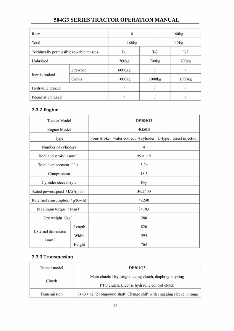
Rear 0 160kg
Total 168kg 112kg
Techincally permissible towable masses T-1 T-2 T-3
Unbraked 700kg 700kg 700kg
Inertia braked Drawbar 6000kg / /
Clevis 1000kg 1000kg 1000kg
Hydraulic braked / / /
Pneumatic braked / / /
2.3.2 Engine
Tractor Model DF504G3
Engine Model 4G50B
Type Four-stroke、water cooled、4 cylinder、L-type、direct injection
Number of cylinders 4
Bore and stroke(mm) 95×115
Total displacement(L) 3.26
Compression 18.5
Cylinder sleeve style Dry
Rated power/speed(kW/rpm) 36/2400
Rate fuel consumption(g/Kw.h) ≤240
Maximum torque(N.m) ≥183
Dry weight(kg) 280
External dimension
(mm)
Length 820
Width 595
Height 763
2.3.3 Transmission
Tractor model DF504G3
Clucth Main clutch: Dry, single-acting clutch, diaphragm spring
PTO clutch: Electric hydraulic control clutch
Transmission (4×3)×2×2 compound shaft, Change shift with engaging sleeve in range
504G3 SERIES TRACTOR OPERATION MANUAL
22
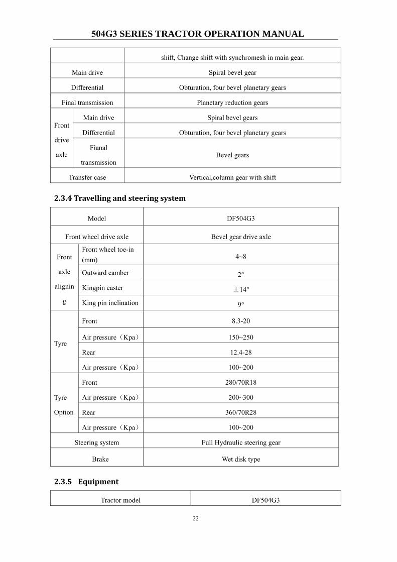
shift, Change shift with synchromesh in main gear.
Main drive Spiral bevel gear
Differential Obturation, four bevel planetary gears
Final transmission Planetary reduction gears
Front
drive
axle
Main drive Spiral bevel gears
Differential Obturation, four bevel planetary gears
Fianal
transmission Bevel gears
Transfer case Vertical,column gear with shift
2.3.4 Travelling and steering system
Model DF504G3
Front wheel drive axle Bevel gear drive axle
Front
axle
alignin
g
Front wheel toe-in (mm) 4~8
Outward camber 2°
Kingpin caster ±14°
King pin inclination 9°
Tyre
Front 8.3-20
Air pressure(Kpa) 150~250
Rear 12.4-28
Air pressure(Kpa) 100~200
Tyre
Option
Front 280/70R18
Air pressure(Kpa) 200~300
Rear 360/70R28
Air pressure(Kpa) 100~200
Steering system Full Hydraulic steering gear
Brake Wet disk type
2.3.5 Equipment
Tractor model DF504G3
504G3 SERIES TRACTOR OPERATION MANUAL
23
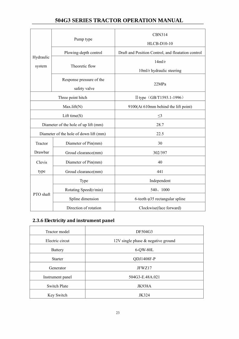
Hydraulic
system
Pump type CBN314
HLCB-D10-10
Plowing-depth control Draft and Position Control, and floatation control
Theoretic flow 14ml/r
10ml/r hydraulic steering
Response pressure of the
safety valve 22MPa
Three point hitch Ⅱtype(GB/T1593.1-1996)
Max.lift(N) 9100(At 610mm behind the lift point)
Lift time(S) ≤3
Diameter of the hole of up lift (mm) 28.7
Diameter of the hole of down lift (mm) 22.5
Tractor
Drawbar
Diameter of Pin(mm) 30
Groud clearance(mm) 302/397
Clevis
type
Diameter of Pin(mm) 40
Groud clearance(mm) 441
PTO shaft
Type Independent
Rotating Speed(r/min) 540、1000
Spline dimension 6-teeth φ35 rectangular spline
Direction of rotation Clockwise(face forward)
2.3.6 Electricity and instrument panel
Tractor model DF504G3
Electric circut 12V single phase & negative ground
Battery 6-QW-80L
Starter QDJ1408F-P
Generator JFWZ17
Instrument panel 504G3-E.48A.021
Switch Plate JK938A
Key Switch JK324
504G3 SERIES TRACTOR OPERATION MANUAL
24
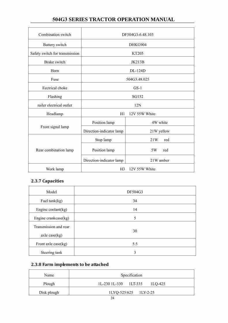
Combination switch DF504G3-6.48.103
Battery switch DHKG904
Safety switch for transmission KT205
Brake switch JK213B
Horn DL-124D
Fuse 504G3.48.025
Eectrical choke GS-1
Flashing SG152
railer electrical outlet 12N
Headlamp H1 12V 55W White
Front signal lamp Position lamp 4W white
Direction-indicator lamp 21W yellow
Rear combination lamp
Stop lamp 21W red
Position lamp 5W red
Direction-indicator lamp 21W amber
Work lamp H3 12V 55W White
2.3.7 Capacities
Model DF504G3
Fuel tank(kg) 34
Engine coolant(kg) 14
Engine crankcase(kg) 5
Transmission and rear
axle case(kg) 30
Front axle case(kg) 5.5
Steering tank 3
2.3.8 Farm implements to be attached
Name Specification
Plough 1L-230 1L-330 1LT-335 1LQ-425
Disk plough 1LYQ-525/625 1LY-2-25
504G3 SERIES TRACTOR OPERATION MANUAL
25
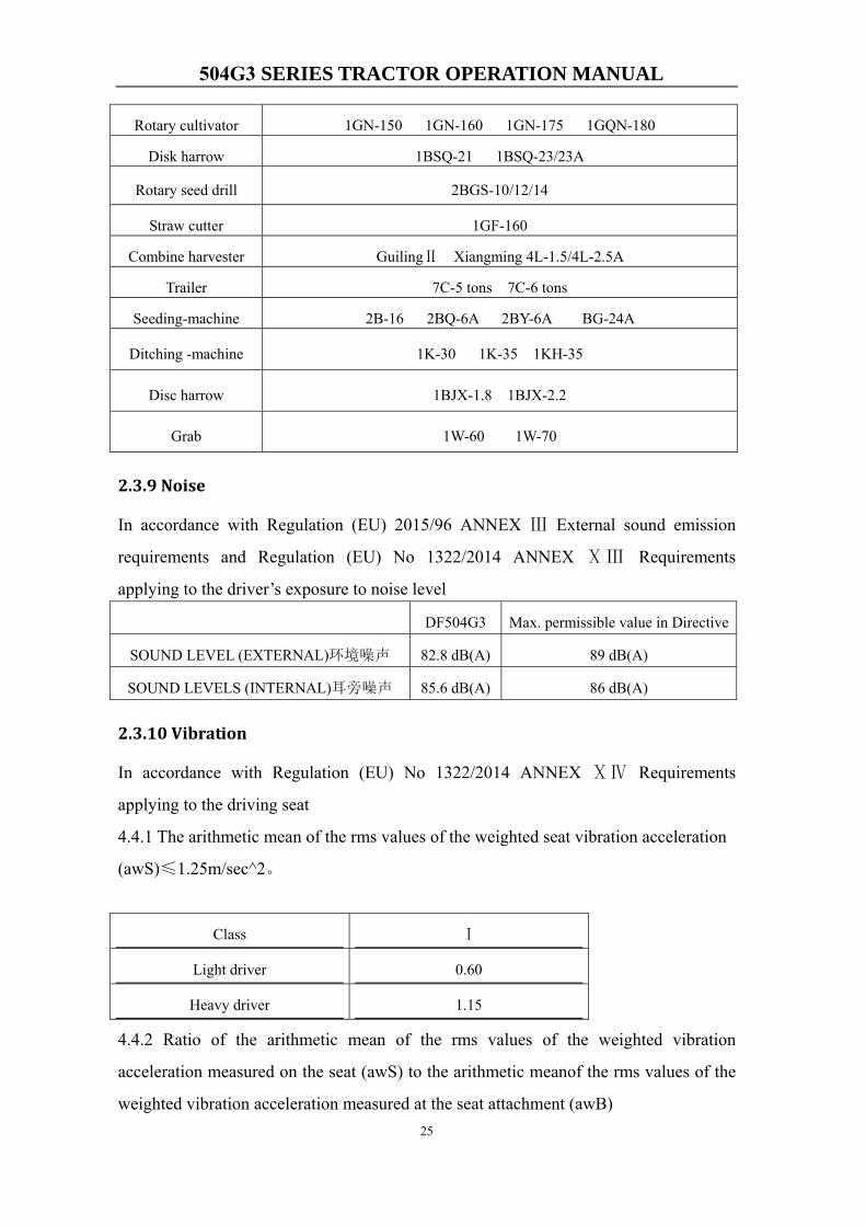
Rotary cultivator 1GN-150 1GN-160 1GN-175 1GQN-180
Disk harrow 1BSQ-21 1BSQ-23/23A
Rotary seed drill 2BGS-10/12/14
Straw cutter 1GF-160
Combine harvester GuilingⅡ Xiangming 4L-1.5/4L-2.5A
Trailer 7C-5 tons 7C-6 tons
Seeding-machine 2B-16 2BQ-6A 2BY-6A BG-24A
Ditching -machine 1K-30 1K-35 1KH-35
Disc harrow 1BJX-1.8 1BJX-2.2
Grab 1W-60 1W-70
2.3.9 Noise
In accordance with Regulation (EU) 2015/96 ANNEX Ⅲ External sound emission
requirements and Regulation (EU) No 1322/2014 ANNEX ⅩⅢ Requirements
applying to the driver’s exposure to noise level
DF504G3 Max. permissible value in Directive
SOUND LEVEL (EXTERNAL)环境噪声 82.8 dB(A) 89 dB(A)
SOUND LEVELS (INTERNAL)耳旁噪声 85.6 dB(A) 86 dB(A)
2.3.10 Vibration
In accordance with Regulation (EU) No 1322/2014 ANNEX ⅩⅣ Requirements
applying to the driving seat
4.4.1 The arithmetic mean of the rms values of the weighted seat vibration acceleration
(awS)≤1.25m/sec^2。
Class Ⅰ
Light driver 0.60
Heavy driver 1.15
4.4.2 Ratio of the arithmetic mean of the rms values of the weighted vibration
acceleration measured on the seat (awS) to the arithmetic meanof the rms values of the
weighted vibration acceleration measured at the seat attachment (awB)

504G3 SERIES TRACTOR OPERATION MANUAL
26
awS/awB≤2
Class Ⅰ
Light driver 0.996
Heavy driver 1.070
504G3 SERIES TRACTOR OPERATION MANUAL
27
Chapter 3 Runningin of the tractor
In order to prolong the service life of tractors, it is essential to break-in a new tractor or
the engine after a major overhaul, before putting it into service. Breaking-in improves
all of the fittings and contact surfaces in order to avoid premature failures.
3.1 Preparation before Running-in of the tractor
1. Please check and tighten the outside screws.
2. Add grease into all the grease fittings.
3. Check the oil lever of engine, gearbox and rear axle, final transmissions, front wheel
drive axle, steering oil tank and hydraulic system. If it is not enough, then supply
again.
4. Fill some fuel and cooling water.
5. Check air pressure of the the tires.
6. Check proportion and height of battery electrolyte.
7. Put Shuttle shift lever, range shift lever and gear shift lever on “netural”
position.Disengage the 4WD. Switch off the PTO switch.
3.2 Running-in the engine without load
Running-in engine for 15 minutes without load.Start the engine in accordance with the
procedure specified in the Instruction Manual, let the engine running-in 7 minutes in
hight speed, 5minutes in mid speed, 3 minutes in high speed.
During the running-in of engine without load, should carefully check the work condition
of engine, air compressor and hydraulic pump.Observe if have abnormality, noise and
check leakages of water, oil and air. If the meters work abnormally, should stop and
remedy the trouble to restart running-in when find abnormality.
Running-in as below when you confirm the engine working is abnormal.
504G3 SERIES TRACTOR OPERATION MANUAL
28
3.3 Running in of hydraulic hitch system
1. Attach ballast or implement whose weight is 800Kg to 3 point hitch system. Push
the position control lever forward all the way to its lower position.
2. Run the engine in low speed for 10 min and in high speed for 10 min.
3. Pull the position control lever backward all the way to its max lift position. Then
control the draft control lever to make the ballast or implement moving from highest
position to lowest position for 10 times.
4. Place the draft control lever in its lowest position. Then control the position control
lever to make the ballast or implement moving from highest position to lowest
position for 10 times. Check whether the position control lever in any position
needed.
5. If hydraulic system operate hardly and lift or low hardly, check trouble immediately.
3.4 Running-in of hydraulic steering system
(1)Park the tractor on the flat road.
(2) Start the engine , let the engine work in low speed, mid speed and high speed. Turn
the steering wheel left and right steady in proper order to do ten times pivot steering.
Check whether the steering is flexible and portable. Check whether the steering system
has oil leak, oil infiltrate and abnormal noise. During the Running-in of hydraulic
steering system, the malfunction should be eliminated in time.
(3) After the engine shutdown, turn the steering left and right slowly , observe the
follow-up condition of tractor front wheel steering to check whether it can realize the
manpower turn .When turning the steering ,do not apply impact force to the steering
wheel.
3.5 Running in of PTO
Put the throttle handle of engine into medium position, the engine will run in idle speed,
switch on the PTO switch to engage PTO clutch. Let the PTO shaft running-in for 5
minutes respectively at low speed and high speed by shifting PTO lever to “LOW” or
504G3 SERIES TRACTOR OPERATION MANUAL
29
“HIGH” position. Check if it is abnormal and must make PTO shaft at Netural position
after running-in.
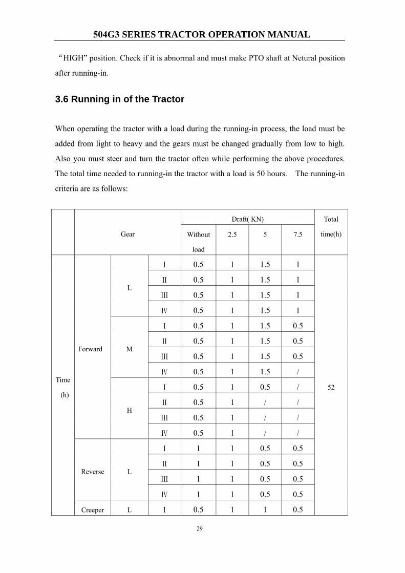
3.6 Running in of the Tractor
When operating the tractor with a load during the running-in process, the load must be
added from light to heavy and the gears must be changed gradually from low to high.
Also you must steer and turn the tractor often while performing the above procedures.
The total time needed to running-in the tractor with a load is 50 hours. The running-in
criteria are as follows:
Gear
Draft( KN) Total
time(h) Without
load
2.5 5 7.5
Time
(h)
Forward
L
Ⅰ 0.5 1 1.5 1
52
Ⅱ 0.5 1 1.5 1
Ⅲ 0.5 1 1.5 1
Ⅳ 0.5 1 1.5 1
M
Ⅰ 0.5 1 1.5 0.5
Ⅱ 0.5 1 1.5 0.5
Ⅲ 0.5 1 1.5 0.5
Ⅳ 0.5 1 1.5 /
H
Ⅰ 0.5 1 0.5 /
Ⅱ 0.5 1 / /
Ⅲ 0.5 1 / /
Ⅳ 0.5 1 / /
Reverse L
Ⅰ 1 1 0.5 0.5
Ⅱ 1 1 0.5 0.5
Ⅲ 1 1 0.5 0.5
Ⅳ 1 1 0.5 0.5
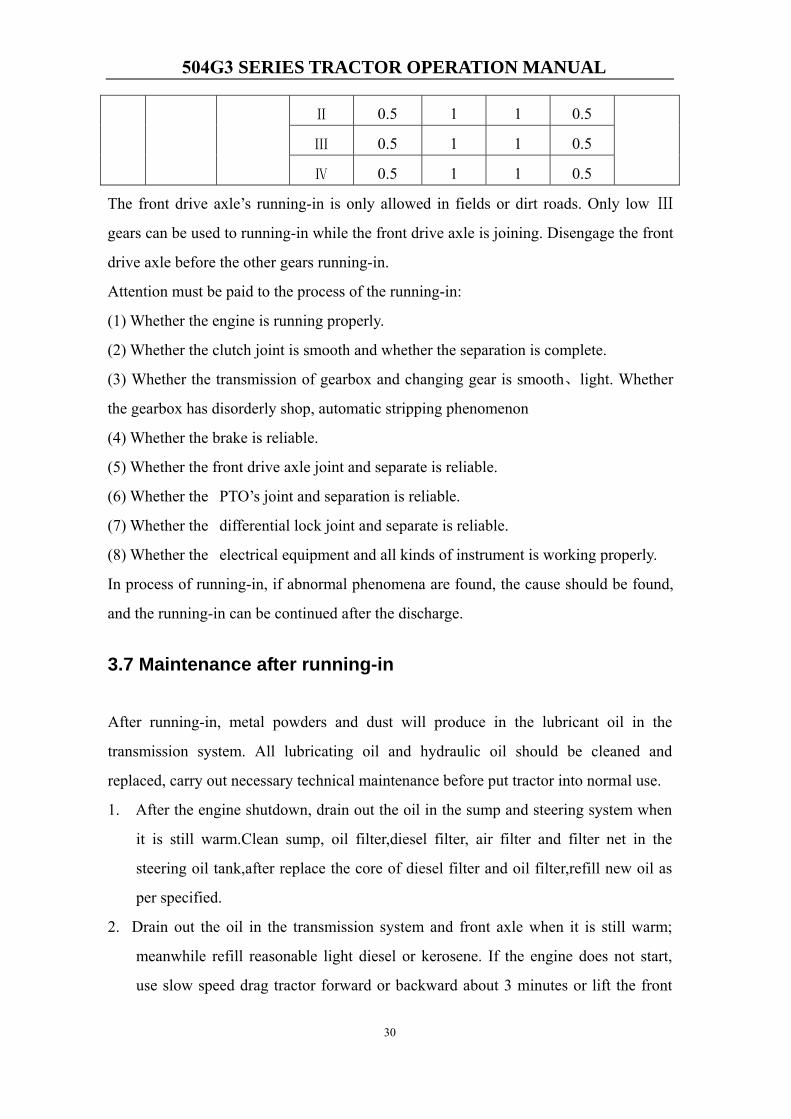
Creeper L Ⅰ 0.5 1 1 0.5
504G3 SERIES TRACTOR OPERATION MANUAL
30
Ⅱ 0.5 1 1 0.5
Ⅲ 0.5 1 1 0.5
Ⅳ 0.5 1 1 0.5
The front drive axle’s running-in is only allowed in fields or dirt roads. Only low Ⅲ
gears can be used to running-in while the front drive axle is joining. Disengage the front
drive axle before the other gears running-in.
Attention must be paid to the process of the running-in:
(1) Whether the engine is running properly.
(2) Whether the clutch joint is smooth and whether the separation is complete.
(3) Whether the transmission of gearbox and changing gear is smooth、light. Whether
the gearbox has disorderly shop, automatic stripping phenomenon
(4) Whether the brake is reliable.
(5) Whether the front drive axle joint and separate is reliable.
(6) Whether the PTO’s joint and separation is reliable.
(7) Whether the differential lock joint and separate is reliable.
(8) Whether the electrical equipment and all kinds of instrument is working properly.
In process of running-in, if abnormal phenomena are found, the cause should be found,
and the running-in can be continued after the discharge.
3.7 Maintenance after running-in
After running-in, metal powders and dust will produce in the lubricant oil in the
transmission system. All lubricating oil and hydraulic oil should be cleaned and
replaced, carry out necessary technical maintenance before put tractor into normal use.
1. After the engine shutdown, drain out the oil in the sump and steering system when
it is still warm.Clean sump, oil filter,diesel filter, air filter and filter net in the
steering oil tank,after replace the core of diesel filter and oil filter,refill new oil as
per specified.
2. Drain out the oil in the transmission system and front axle when it is still warm;
meanwhile refill reasonable light diesel or kerosene. If the engine does not start,
use slow speed drag tractor forward or backward about 3 minutes or lift the front
504G3 SERIES TRACTOR OPERATION MANUAL
31
and rear tires to leave ground. Turn front and rear tires about 3 minutes in two
directions, instantly drain out the cleaning liquid. Meanwhile dismantle inlet oil
filter or lifter to clean, refill new oil to transmission system, lifter and front axle as
per specified after reinstall well.
3. Drain out coolant and after clean cooling system by water.
4. Clean diesel filter and air cleaner.
5. Check front toe-in, clutch, and the free path of brake, adjust it if necessary.
6. Check and fasten all outside bolts, nuts and screws.
7. Check the nozzle and valve clearance.
8. Check the working of electrical system.
9. Refill lubricant grease to each part of the tractor.
504G3 SERIES TRACTOR OPERATION MANUAL
32
Chapter 4 Operating tractor
4.1 Instrument and Controls
To prevent from accident, it is necessary that you are familiar with instrument and
controls.
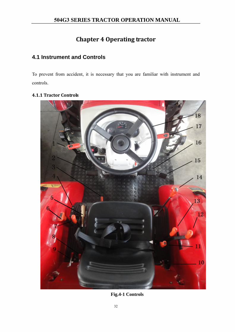
4.1.1 Tractor Controls
Fig.4-1 Controls
504G3 SERIES TRACTOR OPERATION MANUAL
33
1. Shuttle Shift Lever 2. Clucth Pedal 3. Mid PTO Lever 4. FWD Lever 5.Hand Brake
Lever 6. Creer Shift Lever 7. Rear PTO Lever 8. SCV I Lever 9. SCV II Lever 10.
Rapid Lift Lever 11. Range Shift Lever 12. Position Control Lever 13. Draft Control
Lever 14. Gear Shift Lever 15. Foot Throttle 16. Brake Pedal 17. Hand Throttle 18.
Steering Wheel
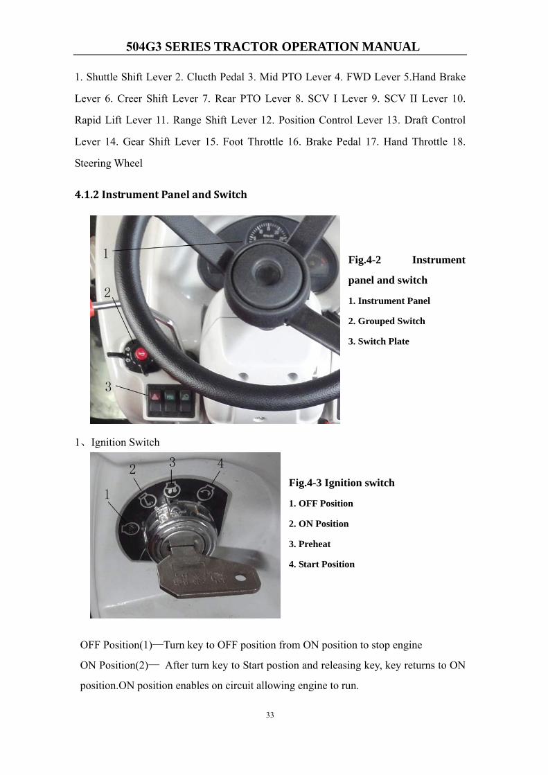
4.1.2 Instrument Panel and Switch
Fig.4-2 Instrument
panel and switch
1. Instrument Panel
2. Grouped Switch
3. Switch Plate
1、Ignition Switch
Fig.4-3 Ignition switch
1. OFF Position
2. ON Position
3. Preheat
4. Start Position
OFF Position(1)—Turn key to OFF position from ON position to stop engine
ON Position(2)— After turn key to Start postion and releasing key, key returns to ON
position.ON position enables on circuit allowing engine to run.
504G3 SERIES TRACTOR OPERATION MANUAL
34
Cold Weather Start(3)—Preheat before start engine in cold weather. Refer the
section“Start in cold weather” in this chapter.
Start Position(4)—Turn key to start position to start engine.
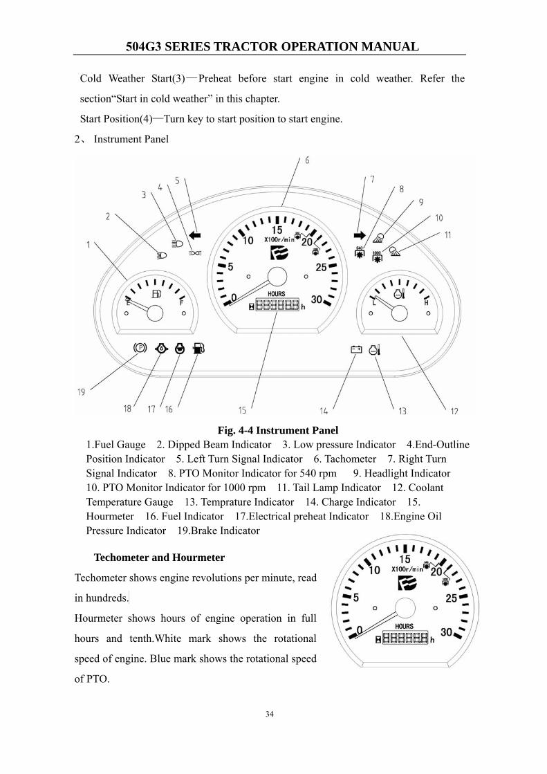
2、 Instrument Panel
Techometer and Hourmeter
Techometer shows engine revolutions per minute, read
in hundreds.
Hourmeter shows hours of engine operation in full
hours and tenth.White mark shows the rotational
speed of engine. Blue mark shows the rotational speed
of PTO.
Fig. 4-4 Instrument Panel 1.Fuel Gauge 2. Dipped Beam Indicator 3. Low pressure Indicator 4.End-OutlinePosition Indicator 5. Left Turn Signal Indicator 6. Tachometer 7. Right TurnSignal Indicator 8. PTO Monitor Indicator for 540 rpm 9. Headlight Indicator10. PTO Monitor Indicator for 1000 rpm 11. Tail Lamp Indicator 12. CoolantTemperature Gauge 13. Temprature Indicator 14. Charge Indicator 15.Hourmeter 16. Fuel Indicator 17.Electrical preheat Indicator 18.Engine OilPressure Indicator 19.Brake Indicator
504G3 SERIES TRACTOR OPERATION MANUAL
35
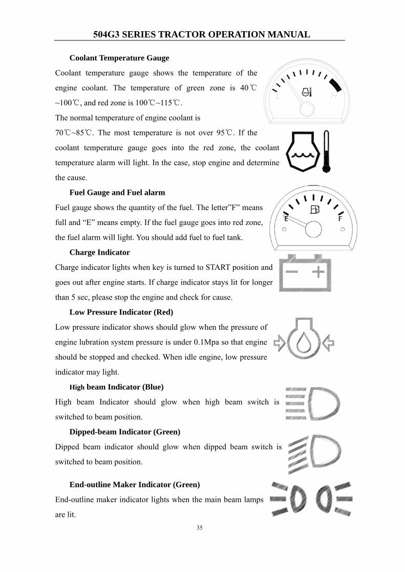
Coolant Temperature Gauge
Coolant temperature gauge shows the temperature of the
engine coolant. The temperature of green zone is 40℃
~100℃, and red zone is 100℃~115℃.
The normal temperature of engine coolant is
70℃~85℃. The most temperature is not over 95℃. If the
coolant temperature gauge goes into the red zone, the coolant
temperature alarm will light. In the case, stop engine and determine
the cause.
Fuel Gauge and Fuel alarm
Fuel gauge shows the quantity of the fuel. The letter”F” means
full and “E” means empty. If the fuel gauge goes into red zone,
the fuel alarm will light. You should add fuel to fuel tank.
Charge Indicator
Charge indicator lights when key is turned to START position and
goes out after engine starts. If charge indicator stays lit for longer
than 5 sec, please stop the engine and check for cause.
Low Pressure Indicator (Red)
Low pressure indicator shows should glow when the pressure of
engine lubration system pressure is under 0.1Mpa so that engine
should be stopped and checked. When idle engine, low pressure
indicator may light.
High beam Indicator (Blue)
High beam Indicator should glow when high beam switch is
switched to beam position.
Dipped-beam Indicator (Green)
Dipped beam indicator should glow when dipped beam switch is
switched to beam position.
End-outline Maker Indicator (Green)
End-outline maker indicator lights when the main beam lamps
are lit.
504G3 SERIES TRACTOR OPERATION MANUAL
36
Left and Right Turn Indicators (Green)
Left and right turn indicators lights when left or right indicator
lamp is lit.
Brake Indicator (Red)
Brake indicator lights when brake is depressed. At one time, the
brake lamp will light.
PTO Monitor Indicator for 540 rpm
Indicates the state of the PTO shaft as follows:
–If the monitor glows, the PTO shaft is rotating at speed of 540 rpm.
PTO Monitor Indicator for 1000 rpmIndicates the state of the PTO shaft as follows:
– If the monitor glows, the PTO shaft is rotating at speed of 1000 rpm
Electrical preheat IndicatorWhen ignition switch is on ‘Preheat’ position, thi indicates is working.
Headlight Indicator and Tail Lamp Indicator
Headlight Indicator should glow when Headlight switch is switched
to beam position.
Tail Lamp Indicator should glow when Tail Lamp switch is switched to beam position.
3、Combination Switch:
Fig.4-5 Combination switch
1. Turn indicator switch
2. Horn switches
3. Main beam switch
Turn indicator switch 1 is used to switch on the right or left turn indicator lamp. Turn
switch 1 clockwise to switch on right indicator lamp. Turn button 1 counterclockwise to
switch on the left indicator lamp. Turn indicator switch is not functional when hazard
warning signals flashing.
Switch off hazard warning signal with hazard warning switch before operating turn

504G3 SERIES TRACTOR OPERATION MANUAL
37
indicator switch.
Push down horn switch 2 to swith on horn. The button 2 will return to initial postion
after releasing.
Turn main beam switch 3 to control the main beam lamp.
4、Switch plate:
Fig.4-6 Switch plate
1. Hazard-warning signal Switch
2. PTO Switch
3. Rear Work Lamp
(1) Hazard-warning signal switch
It is only used to switch ON the hazard-warning signal.
Hazard-warning signal should light when tractor should be
repaired on road or running in night. “1” is ON position.
(2) PTO Switch
It is only used to engage PTO. When the speed of PTO shaft
Should be changed, place switch on “0” position where
PTO is disengaged.
(3) Rear Work Lamp Switch
It is only used to switch on the
rear work lamp. “1” is ON
position. Rear work lamps are
installed on left and right
fenders.
Fig.4-7
1. Rear Work Lamp
01
1 0
PTO
01
504G3 SERIES TRACTOR OPERATION MANUAL
38
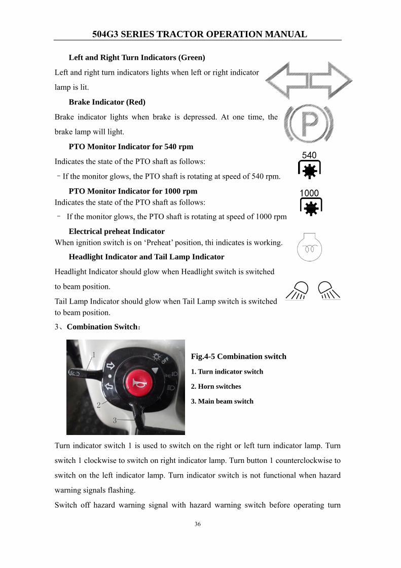
5、Functions of the switches in cab:
Fig 4-8
1. Windshield Wiper Switch
2. Heater Switch
(1) Windshield Wiper Switch
This switch controls the windshield wiper. See figure at right,
“0”position means turn off the switch, and “1”position means
turn on.
(2) Heater Switch
This switch controls the heater for the CAB/
The heater heats the CAB with hot water from engine radiator.
See figure at right, put the switch on “1”position to engage the
heater, the warm wind will be blown out form the air outlet in CAB.
And“0” position to turn off the heater.
(3) Use and adjustment of system for heating
a.Firstly check the hose fixed on the engine, and make
sure it is reliable.and check the hose clamps,make
sure it is fixed and reliable.See figure at right.
b.Starting the engine and keep the idle speed state 5 minutes,then press down the
heater switch. The warm wind will be blown out
form the air outlet in CAB.
c.There are six circular outlets in CAB,and each
outlet can be opened or closed. See figure at right.
1 2
504G3 SERIES TRACTOR OPERATION MANUAL
39
d.There are two rectangle outlets in CAB,
the windowing blade can swing up or
down and left or right,to adjust the
wind direction.
e.There are two strip outlets in CAB, they
are used defrosting for Windshield.
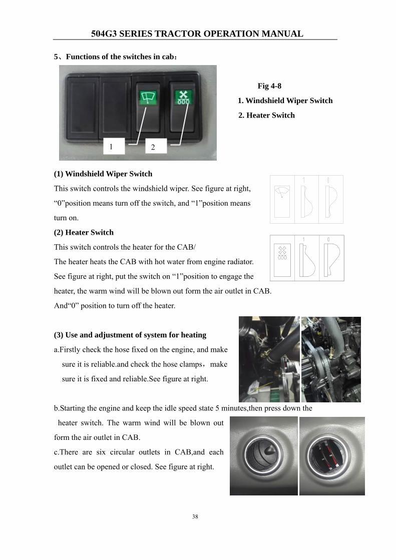
6、Radio control panel in CAB
Fig. 4-9
1.Mode Switch 2. Power Switch 3. Radio seletion-/Next teack 4. Mute the sound
5. Preset station 2/INT 6.Preset station 3/RPT 7. Preset station 5/10- 8.USB SLOT
9. SD/MMC CARD PORT 10. Sount Files/Automatic preset station 11. Radio
seletion+/previous track 12.Clock function/According to three seconds clock adjust
13.Radio band seletion 14.Preset station1 /Player pause 15.Preset station 4/RDM
16.Preset station 6/10+ 17.AUX/IN
2 1
10
3 4
11 12 13 14
5 6
15
7
16 17
8 9
504G3 SERIES TRACTOR OPERATION MANUAL
40
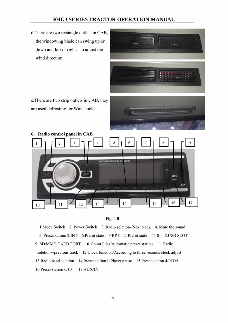
7、Radio horn
Above the back of the CAB,there are
two loudspeakers.When opening the radio,
the sound will come out from the
loudspeaker.
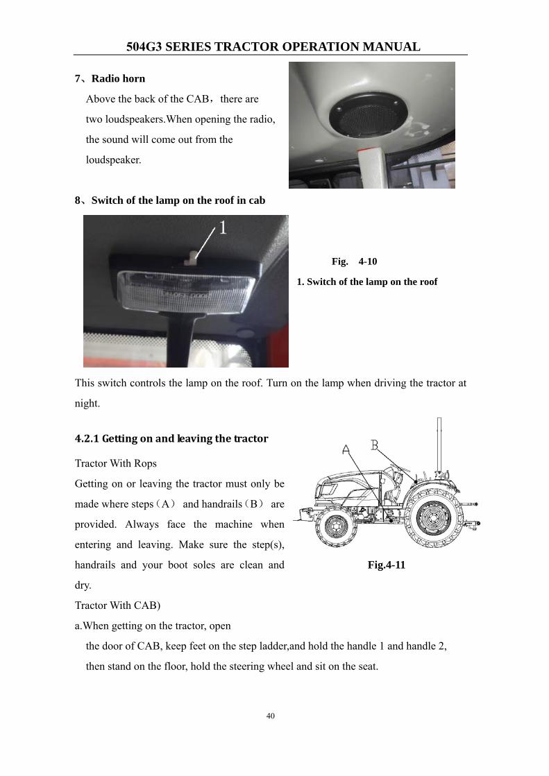
8、Switch of the lamp on the roof in cab
Fig. 4-10
1. Switch of the lamp on the roof
This switch controls the lamp on the roof. Turn on the lamp when driving the tractor at
night.
4.2.1 Getting on and leaving the tractor
Tractor With Rops
Getting on or leaving the tractor must only be
made where steps(A) and handrails(B) are
provided. Always face the machine when
entering and leaving. Make sure the step(s),
handrails and your boot soles are clean and
dry.
Tractor With CAB)
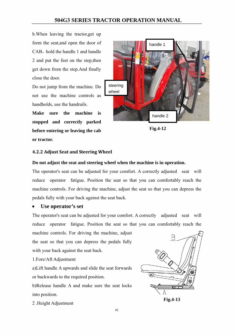
a.When getting on the tractor, open
the door of CAB, keep feet on the step ladder,and hold the handle 1 and handle 2,
then stand on the floor, hold the steering wheel and sit on the seat.
Fig.4-11
504G3 SERIES TRACTOR OPERATION MANUAL
41
b.When leaving the tractor,get up
form the seat,and open the door of
CAB,hold the handle 1 and handle
2 and put the feet on the step,then
get down from the step.And finally
close the door.
Do not jump from the machine. Do
not use the machine controls as
handholds, use the handrails.
Make sure the machine is
stopped and correctly parked
before entering or leaving the cab
or tractor.
4.2.2 Adjust Seat and Steering Wheel
Do not adjust the seat and steering wheel when the machine is in operation.
The operator's seat can be adjusted for your comfort. A correctly adjusted seat will
reduce operator fatigue. Position the seat so that you can comfortably reach the
machine controls. For driving the machine, adjust the seat so that you can depress the
pedals fully with your back against the seat back.
• Use operator’s setThe operator's seat can be adjusted for your comfort. A correctly adjusted seat will
reduce operator fatigue. Position the seat so that you can comfortably reach the
machine controls. For driving the machine, adjust
the seat so that you can depress the pedals fully
with your back against the seat back.
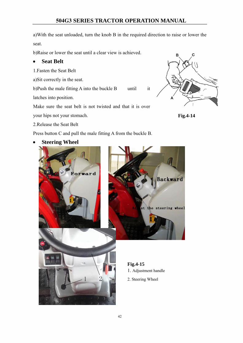
1.Fore/Aft Adjustment
a)Lift handle A upwards and slide the seat forwards
or backwards to the required position.
b)Release handle A and make sure the seat locks
into position.
2 .Height AdjustmentFig.4-13
handle 2
steering wheel
handle 1
Fig.4-12
504G3 SERIES TRACTOR OPERATION MANUAL
42
a)With the seat unloaded, turn the knob B in the required direction to raise or lower the
seat.
b)Raise or lower the seat until a clear view is achieved.
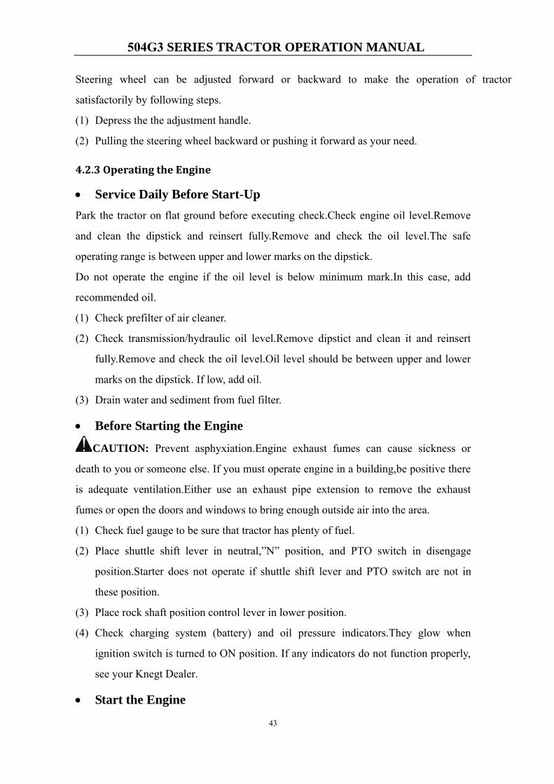
• Seat Belt1.Fasten the Seat Belt
a)Sit correctly in the seat.
b)Push the male fitting A into the buckle B until it
latches into position.
Make sure the seat belt is not twisted and that it is over
your hips not your stomach.
2.Release the Seat Belt
Press button C and pull the male fitting A from the buckle B.
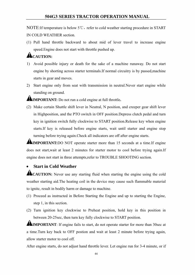
• Steering Wheel
Fig.4-14
Fig.4-15 1. Adjustment handle
2. Steering Wheel
504G3 SERIES TRACTOR OPERATION MANUAL
43
Steering wheel can be adjusted forward or backward to make the operation of tractor
satisfactorily by following steps.
(1) Depress the the adjustment handle.
(2) Pulling the steering wheel backward or pushing it forward as your need.
4.2.3 Operating the Engine
• Service Daily Before Start-UpPark the tractor on flat ground before executing check.Check engine oil level.Remove
and clean the dipstick and reinsert fully.Remove and check the oil level.The safe
operating range is between upper and lower marks on the dipstick.
Do not operate the engine if the oil level is below minimum mark.In this case, add
recommended oil.
(1) Check prefilter of air cleaner.
(2) Check transmission/hydraulic oil level.Remove dipstict and clean it and reinsert
fully.Remove and check the oil level.Oil level should be between upper and lower
marks on the dipstick. If low, add oil.
(3) Drain water and sediment from fuel filter.
• Before Starting the Engine
CAUTION: Prevent asphyxiation.Engine exhaust fumes can cause sickness or
death to you or someone else. If you must operate engine in a building,be positive there
is adequate ventilation.Either use an exhaust pipe extension to remove the exhaust
fumes or open the doors and windows to bring enough outside air into the area.
(1) Check fuel gauge to be sure that tractor has plenty of fuel.
(2) Place shuttle shift lever in neutral,”N” position, and PTO switch in disengage
position.Starter does not operate if shuttle shift lever and PTO switch are not in
these position.
(3) Place rock shaft position control lever in lower position.
(4) Check charging system (battery) and oil pressure indicators.They glow when
ignition switch is turned to ON position. If any indicators do not function properly,
see your Knegt Dealer.
• Start the Engine
504G3 SERIES TRACTOR OPERATION MANUAL
44
NOTE:If temperature is below 5℃,refer to cold weather starting procedure in START
IN COLD WEATHER section.
(1) Pull hand throttle backward to about mid of lever travel to increase engine
speed.Engine does not start with throttle pushed up.
CAUTION:
1) Avoid possible injury or death for the sake of a machine runaway. Do not start
engine by shorting across starter terminals.If normal circuitry is by passed,machine
starts in gear and moves.
2) Start engine only from seat with transmission in neutral.Never start engine while
standing on ground.
IMPORTANT: Do not run a cold engine at full throttle.
(2) Make certain Shuttle shift lever in Neutral, N position, and creeper gear shift lever
in Highposition, and the PTO switch in OFF position.Depress clutch pedal and turn
key in ignition switch fully clockwise to START position.Release key when engine
starts.If key is released before engine starts, wait until starter and engine stop
turning before trying again.Check all indicators are off after engine starts.
IMPORTANT:DO NOT operate starter more than 15 seconds at a time.If engine
does not start,wait at least 2 minutes for starter motor to cool before trying again.If
engine does not start in three attempts,refer to TROUBLE SHOOTING section.
• Start in Cold Weather
CAUTION: Never use any starting fluid when starting the engine using the cold
weather starting aid.The heating coil in the device may cause such flammable material
to ignite, result in bodily harm or damage to machine.
(1) Proceed as instructed in Before Starting the Engine and up to starting the Engine,
step 1, in this section.
(2) Turn ignition key clockwise to Preheat position, hold key in this position in
between 20-25sec, then turn key fully clockwise to START position.
IMPORTANT: If engine fails to start, do not operate starter for more than 30sec at
a time.Turn key back to OFF postion and wait at least 2 minute before trying again,
allow starter motor to cool off.
After engine starts, do not adjust hand throttle lever. Let engine run for 3-4 minute, or if
504G3 SERIES TRACTOR OPERATION MANUAL
45
the temperature is blew 0℃, extend warm-up period accordingly.
• Check Instruments after Starting
IMPORTANT: If charging system indicator or oil pressure indicator remains ON, or if
coolant temperature gauge goes into the red zone, stop engine and determine the cause.
(1) Oil Pressure Indicator
Oil pressure indicator lights and stay lit when engine oil pressure falls below minmum.
IMPORTANT: Never operate engine without sufficient oil pressure. If indicator
light stays lit for longer than 5 seconds under normal operating conditions, stop engine
and check for cause.
If low oil level is not the promble, see your Knegt dealer.
(2) Charging Systm Indicator
Charging system indicator lights when alternator output is low.Charging system
indicator lights when key is turned to ON and START position, and goes out when
engine starts. If indicator light stays lit for longer than 5 seconds under normal
operating conditions, stop engine and check for cause.
If loose or broken fan belt is not the cause, see your Knegt dealer.
(3) Coolant Temperature Gauge
The needle on the temperature gauge rises as engine warms up. If needle reaches to red
zone, stop engine and determine the cause.
Check coolant level in radiator when engine cools.Also check front grille, radiator for
plugging. Check fan belt tension. If problem is not corrected, see your Knegt dealer.
CAUTION: Do not remove radiator cap until coolant has had a chance to cool down.
Always loosen radiator cap slowly to relieve excess pressure.
(4) Watch Fuel Level
Stop to refuel before needle on fuel gauge reaches empty mark.
If tractor run out of fuel and not start in several tries, air must be bled from fuel system.
(See Bleed Fuel System, in Maitanence-Fuel System section)
• Warm Up the Engine
The throttle should be reduced immediately afte starting engine. Idle the engine at about
1500 rpm for several minutes. Run engine at a low speed and under light load until
coolant reach 60℃.
504G3 SERIES TRACTOR OPERATION MANUAL
46
4.2.4 Start the Tractor
1. Loose the park brake system and press the horn then check the surroundings.
2. Depress the clutch pedal to the end, shift to a proper gear. If it fails, then loose the
clutch pedal, and do these procedures again.
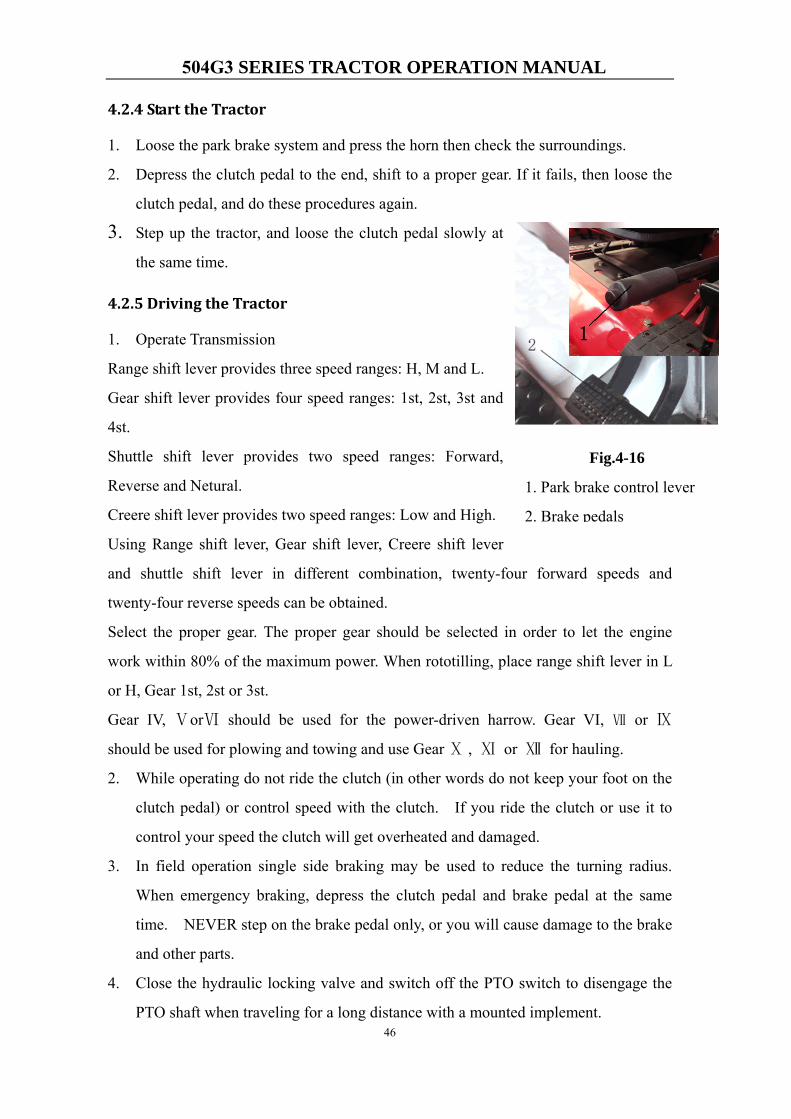
3. Step up the tractor, and loose the clutch pedal slowly at
the same time.
4.2.5 Driving the Tractor
1. Operate Transmission
Range shift lever provides three speed ranges: H, M and L.
Gear shift lever provides four speed ranges: 1st, 2st, 3st and
4st.
Shuttle shift lever provides two speed ranges: Forward,
Reverse and Netural.
Creere shift lever provides two speed ranges: Low and High.
Using Range shift lever, Gear shift lever, Creere shift lever
and shuttle shift lever in different combination, twenty-four forward speeds and
twenty-four reverse speeds can be obtained.
Select the proper gear. The proper gear should be selected in order to let the engine
work within 80% of the maximum power. When rototilling, place range shift lever in L
or H, Gear 1st, 2st or 3st.
Gear IV, ⅤorⅥ should be used for the power-driven harrow. Gear VI, Ⅶ or Ⅸ
should be used for plowing and towing and use Gear Ⅹ , Ⅺ or Ⅻ for hauling.
2. While operating do not ride the clutch (in other words do not keep your foot on the
clutch pedal) or control speed with the clutch. If you ride the clutch or use it to
control your speed the clutch will get overheated and damaged.
3. In field operation single side braking may be used to reduce the turning radius.
When emergency braking, depress the clutch pedal and brake pedal at the same
time. NEVER step on the brake pedal only, or you will cause damage to the brake
and other parts.
4. Close the hydraulic locking valve and switch off the PTO switch to disengage the
PTO shaft when traveling for a long distance with a mounted implement.
Fig.4-16
1. Park brake control lever
2. Brake pedals
504G3 SERIES TRACTOR OPERATION MANUAL
47
5. When using the tractor in a dry field you may install the rear wheel balance weight
(optional) in order to make full use of the traction force.
NOTE: when the main speed should be shifted, the creeper should be put on the high gear
(rabbit), and if the range should be shifted, then put the main speed in neutral.
• Use of the Brakes
CAUTION: Before operating a tractor on a road, interlock brake pedals together
with locking bar. Use brakes lightly and cautiously at transport speed.
For field work, brake pedals should not be interlocked together. Instead, apply right
brake pedal to assist in making sharp right turn and left pedal for sharp left turn.
To stop a tractor, interlock brake pedals together with locking bar, depress brake pedals.
Put gear shift in “Netural” position and shuttle shift in “Netural” position, then pull the
hand brake lever up fully.
• Use of the Differential Lock
When one wheel starts to lose traction, you can engage the differential lock as following
steps:
(1) Stop the tractor.
NOTE: Tractor wheels must be stopped or turning at the same speed before
engaging differential lock. If possible, engage differential lock before entering the area
where tires may slip.
(2) Depress clutch pedal, place creeper shift lever in “rabbit” position, range shift lever
in ”L” position, and gear shift lever in”I” postion.
(3) Depress differential lock pedal down.
(4) Slowly loosen clutch pedal.Then tractor will run out of the area where tires slip. If
tires repeatly slip, then get traction, and then slip again, hold pedal in the engaged
504G3 SERIES TRACTOR OPERATION MANUAL
48
position.
Note: Unequal traction keeps the lock engaged.
When traction equalizes, lock disengages itself by spring action. If lock does not
disengage, depress one brake pedal and then the other.
CAUTION: Do not operate tractor at high speed or attempt to turn with differential
lock engaged. To prevent damage to drive train, do not engage differential lock when
one wheel is spinning and the other is completely stopped.
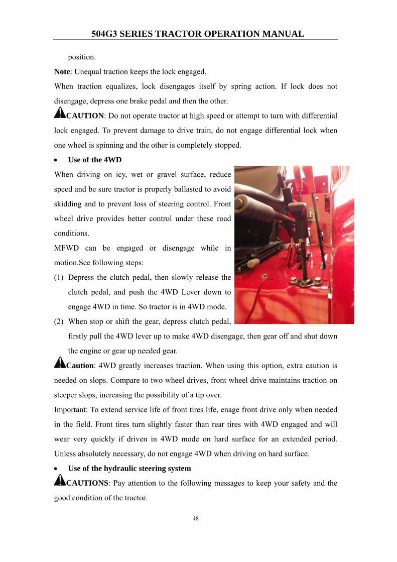
• Use of the 4WD
When driving on icy, wet or gravel surface, reduce
speed and be sure tractor is properly ballasted to avoid
skidding and to prevent loss of steering control. Front
wheel drive provides better control under these road
conditions.
MFWD can be engaged or disengage while in
motion.See following steps:
(1) Depress the clutch pedal, then slowly release the
clutch pedal, and push the 4WD Lever down to
engage 4WD in time. So tractor is in 4WD mode.
(2) When stop or shift the gear, depress clutch pedal,
firstly pull the 4WD lever up to make 4WD disengage, then gear off and shut down
the engine or gear up needed gear.
Caution: 4WD greatly increases traction. When using this option, extra caution is
needed on slops. Compare to two wheel drives, front wheel drive maintains traction on
steeper slops, increasing the possibility of a tip over.
Important: To extend service life of front tires life, enage front drive only when needed
in the field. Front tires turn slightly faster than rear tires with 4WD engaged and will
wear very quickly if driven in 4WD mode on hard surface for an extended period.
Unless absolutely necessary, do not engage 4WD when driving on hard surface.
• Use of the hydraulic steering system
CAUTIONS: Pay attention to the following messages to keep your safety and the
good condition of the tractor.
504G3 SERIES TRACTOR OPERATION MANUAL
49
(1) Don’t turn the steering wheel with force if it’s hard to turn the wheel. At first you
should check the system and eliminate problems.
(2) If the steering pump is broken or the engine can not work, and the tractor must be
moved away, you should turn the steering wheel slowly. No sudden force is allowed,
or the components of the steering system may be damaged.
(3) Do not remove and adjust the steering pump by oneself. It may change the pressure
of the valve.
CAUTION:
(1) When the tractor travels at a high speed, don’t make an emergency turn with single
brake.
(2) If the steering angle of the front wheels is too big, and there is a noise in the valve,
you should turn the steering wheel back a little to prevent overload of the hydraulic
system.
• Use of the tires
As the damageable parts of the tractor, tires should be paid attention on their
maintenance to extend their life.
Inflate the tires according to the regulations, if the pressure is too low or too high is not
permit.
Avoid travelling over the barrier at a high speed.
The tires should be kept away from chemic stuff, such as acid and oil.
Check toe-in to avoid unnatural wear of tires. If the wear is asymmetric, exchange the
left and right tire.
When mounting the tire, pay attention to direction of the tire pattern.
4.2.6 Stopping Tractor
CAUTION: Always pull up the Park Brake Lever fully before dismounting.
Leaving transmission in gear with engine off may not prevent tractor from moving.
1. Reduce the throttle to slow down the tractor.
2. Depress the clutch pedal and depress the brake pedal to stop the tractor, and then
place the gear shift lever and Shuttle shift lever in “Neutral” position. And then
loosen the clutch and brake pedals.
3. Pull hand throttle down to slow idle position.Allow engine to idle for 1 to 2 min.
504G3 SERIES TRACTOR OPERATION MANUAL
50
Wait the temperature of coolant decrease to below 70℃.
IMPORTANT: Engine oil provides cooling of certain engine parts. Stopping a
hot engine suddently could damage these parts by overheating or lack of lubrication.
4. Turn key switch to STOP position.Then remove key from key switch to prevent
operation by untrained personnel.
5. If place the tractor on a slop, please pull up the hand brake lever fully.
6. Drain off the cooling water in winter.
CAUTION:
(1) The operator can not leave with the engine on. And it’s necessary to keep the
shuttle and main gear shift levers in neutral.
(2) If the tractor stopped on a slope, the engine must be shut down. At the same time,
shift the shuttle and main speed into gear (upgrade with the shuttle forward and
downgrade with the shuttle reverse). Lock the tires with chocks.
4.2.7 Draw the Tractor
1. Turn switch key to OFF position.
2. Place Shuttle shift lever in Netural position, Creer shift lever to “Neutral” position,
Range shift lever in H position, Gear shift lever in “Neutral” position
3. The draw speed must be lower than 18 km/h.
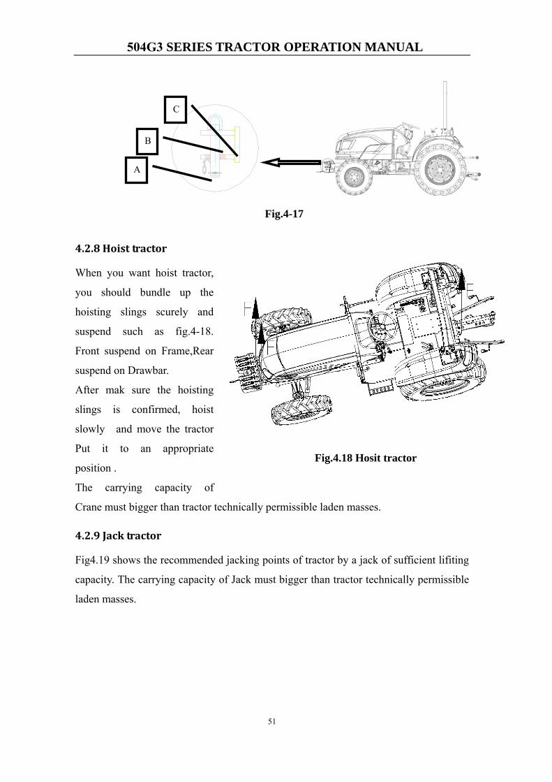
How to draw the tractor
You have tow ways for draw tractor , you can use hook catch B (Bolt weldment) and
also you can put rope to C area: you should take out A (Pin) from B, then take out
B ,and put rope toC area ,then install B and A.
504G3 SERIES TRACTOR OPERATION MANUAL
51
4.2.8 Hoist tractor
When you want hoist tractor,
you should bundle up the
hoisting slings scurely and
suspend such as fig.4-18.
Front suspend on Frame,Rear
suspend on Drawbar.
After mak sure the hoisting
slings is confirmed, hoist
slowly and move the tractor
Put it to an appropriate
position .
The carrying capacity of
Crane must bigger than tractor technically permissible laden masses.
4.2.9 Jack tractor
Fig4.19 shows the recommended jacking points of tractor by a jack of sufficient lifiting
capacity. The carrying capacity of Jack must bigger than tractor technically permissible
laden masses.
A
C
B
Fig.4-17
Fig.4.18 Hosit tractor

504G3 SERIES TRACTOR OPERATION MANUAL
52
4.3 Using the Tractor implents
4.3.1 Hydraulic lift system control lever
Fig 4-20
1、Draft Control Lever
2、Position Control Lever
3、Rapid Lift Lever
1、 Draft Control
Use draft control lever to control the depth changes in a range, so keep the draft load
constant automatically. This method is often applied when soil condition is almost the same.
See figure 4-21(a)
Move the position control lever all the way forward, then push the draft control lever
forward at desired depth.
A
C
B
Fig.4-17
Fig. 4-19 A——Front jacking point B——Middle jacking point of Axles C——Rear jacking point
504G3 SERIES TRACTOR OPERATION MANUAL
53
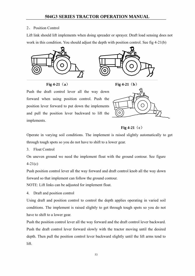
2、 Position Control
Lift link should lift implements when doing spreader or sprayer. Draft load sensing does not
work in this condition. You should adjust the depth with position control. See fig 4-21(b)
Fig 4-21(a) Fig 4-21(b)
Push the draft control lever all the way down
forward when using position control. Push the
position lever forward to put down the implements
and pull the position lever backward to lift the
implements.
Fig 4-21(c)
Operate in varying soil conditions. The implement is raised slightly automatically to get
through tough spots so you do not have to shift to a lower gear.
3. Float Control
On uneven ground we need the implement float with the ground contour. See figure
4-21(c)
Push position control lever all the way forward and draft control knob all the way down
forward so that implement can follow the ground contour.
NOTE: Lift links can be adjusted for implement float.
4. Draft and position control
Using draft and position control to control the depth applies operating in varied soil
conditions. The implement is raised slightly to get through tough spots so you do not
have to shift to a lower gear.
Push the position control lever all the way forward and the draft control lever backward.
Push the draft control lever forward slowly with the tractor moving until the desired
depth. Then pull the position control lever backward slightly until the lift arms tend to
lift.
504G3 SERIES TRACTOR OPERATION MANUAL
54
5. Rapid lift control
When the tractor turnaround in the end of the field or leaves the field or transport, the
rapid lift lever can be used to lift the implement quickly (fig. 4-20). Using the rapid lift
lever can lightening the burden of the driver.
Pull up the rapid lift lever to realize rapid lift. Keep it down when you don’t need this
function.
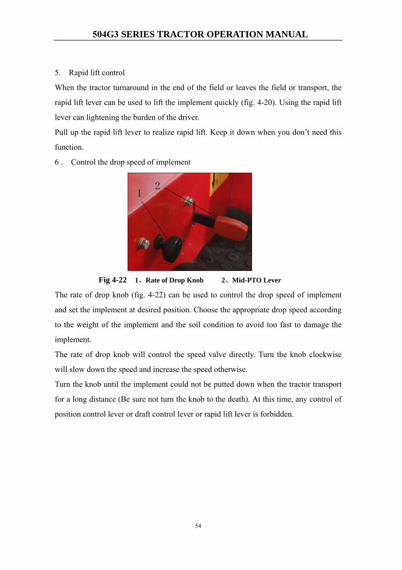
6 . Control the drop speed of implement
Fig 4-22 1、Rate of Drop Knob 2、Mid-PTO Lever
The rate of drop knob (fig. 4-22) can be used to control the drop speed of implement
and set the implement at desired position. Choose the appropriate drop speed according
to the weight of the implement and the soil condition to avoid too fast to damage the
implement.
The rate of drop knob will control the speed valve directly. Turn the knob clockwise
will slow down the speed and increase the speed otherwise.
Turn the knob until the implement could not be putted down when the tractor transport
for a long distance (Be sure not turn the knob to the death). At this time, any control of
position control lever or draft control lever or rapid lift lever is forbidden.
504G3 SERIES TRACTOR OPERATION MANUAL
55
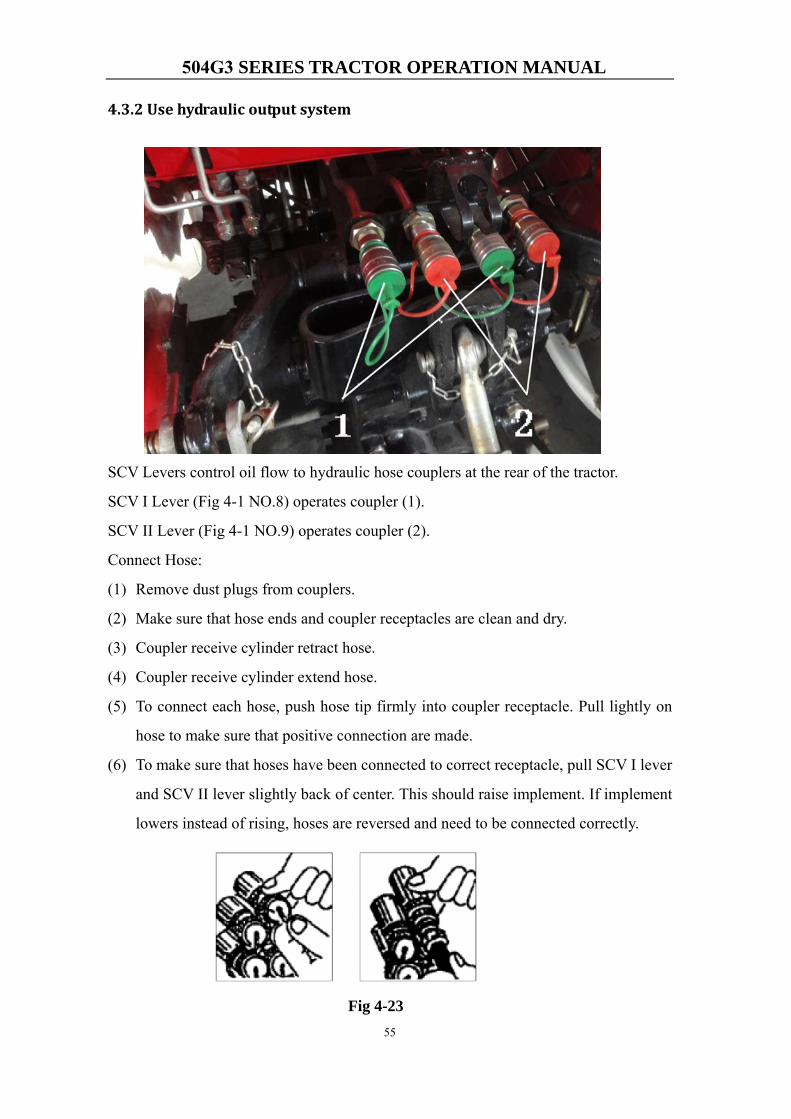
4.3.2 Use hydraulic output system
SCV Levers control oil flow to hydraulic hose couplers at the rear of the tractor.
SCV I Lever (Fig 4-1 NO.8) operates coupler (1).
SCV II Lever (Fig 4-1 NO.9) operates coupler (2).
Connect Hose:
(1) Remove dust plugs from couplers.
(2) Make sure that hose ends and coupler receptacles are clean and dry.
(3) Coupler receive cylinder retract hose.
(4) Coupler receive cylinder extend hose.
(5) To connect each hose, push hose tip firmly into coupler receptacle. Pull lightly on
hose to make sure that positive connection are made.
(6) To make sure that hoses have been connected to correct receptacle, pull SCV I lever
and SCV II lever slightly back of center. This should raise implement. If implement
lowers instead of rising, hoses are reversed and need to be connected correctly.
Fig 4-23
504G3 SERIES TRACTOR OPERATION MANUAL
56
Disconnect cylinder hoses
IMPORTANT: When disconnecting hoses, always grasp metal tip, never the hose itself.
Pulling on the hose instead of metal tip will eventually damage hose.
To disconnect hoses, grasp hose tip and give a firm pull.
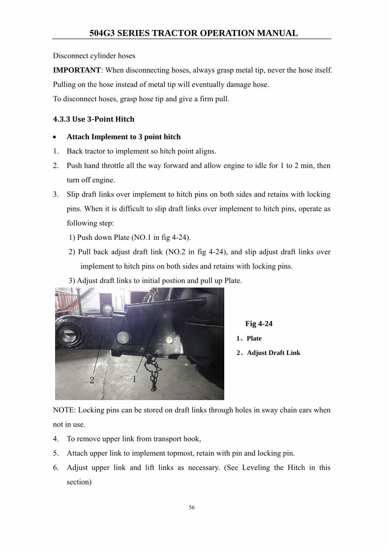
4.3.3 Use 3Point Hitch
• Attach Implement to 3 point hitch
1. Back tractor to implement so hitch point aligns.
2. Push hand throttle all the way forward and allow engine to idle for 1 to 2 min, then
turn off engine.
3. Slip draft links over implement to hitch pins on both sides and retains with locking
pins. When it is difficult to slip draft links over implement to hitch pins, operate as
following step:
1) Push down Plate (NO.1 in fig 4-24).
2) Pull back adjust draft link (NO.2 in fig 4-24), and slip adjust draft links over
implement to hitch pins on both sides and retains with locking pins.
3) Adjust draft links to initial postion and pull up Plate.
Fig 4-24
1、Plate
2、Adjust Draft Link
NOTE: Locking pins can be stored on draft links through holes in sway chain ears when
not in use.
4. To remove upper link from transport hook,
5. Attach upper link to implement topmost, retain with pin and locking pin.
6. Adjust upper link and lift links as necessary. (See Leveling the Hitch in this
section)
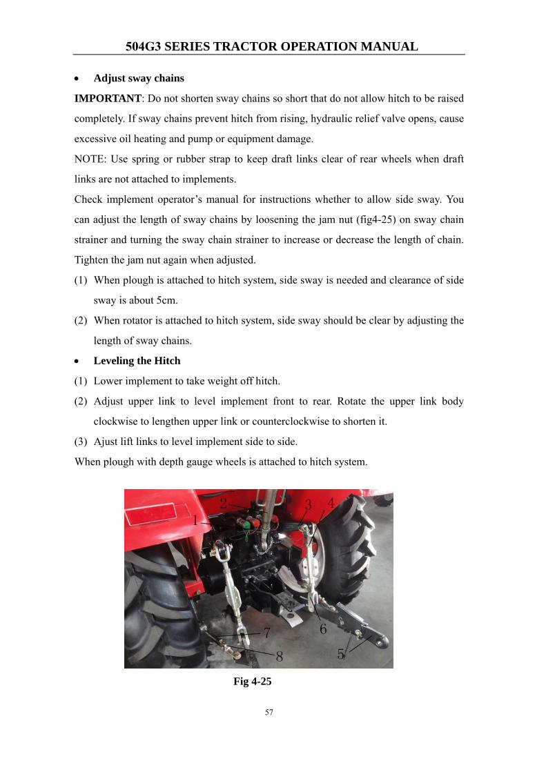
504G3 SERIES TRACTOR OPERATION MANUAL
57
• Adjust sway chains
IMPORTANT: Do not shorten sway chains so short that do not allow hitch to be raised
completely. If sway chains prevent hitch from rising, hydraulic relief valve opens, cause
excessive oil heating and pump or equipment damage.
NOTE: Use spring or rubber strap to keep draft links clear of rear wheels when draft
links are not attached to implements.
Check implement operator’s manual for instructions whether to allow side sway. You
can adjust the length of sway chains by loosening the jam nut (fig4-25) on sway chain
strainer and turning the sway chain strainer to increase or decrease the length of chain.
Tighten the jam nut again when adjusted.
(1) When plough is attached to hitch system, side sway is needed and clearance of side
sway is about 5cm.
(2) When rotator is attached to hitch system, side sway should be clear by adjusting the
length of sway chains.
• Leveling the Hitch
(1) Lower implement to take weight off hitch.
(2) Adjust upper link to level implement front to rear. Rotate the upper link body
clockwise to lengthen upper link or counterclockwise to shorten it.
(3) Ajust lift links to level implement side to side.
When plough with depth gauge wheels is attached to hitch system.
Fig 4-25
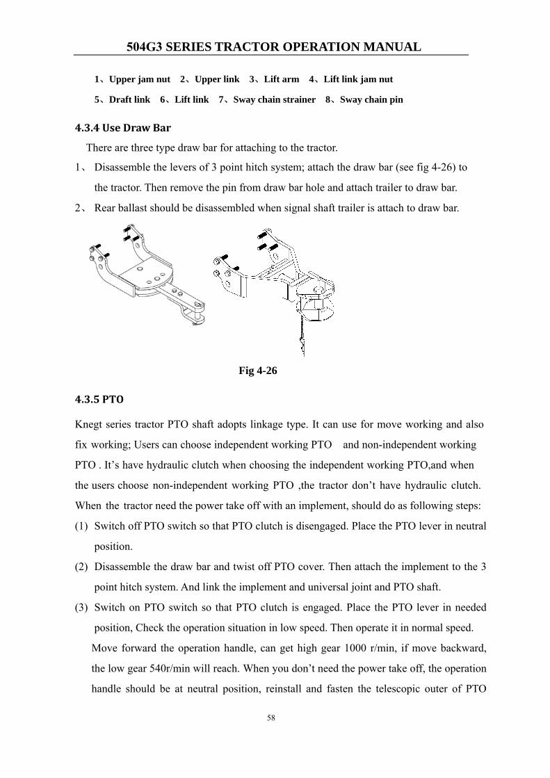
504G3 SERIES TRACTOR OPERATION MANUAL
58
1、Upper jam nut 2、Upper link 3、Lift arm 4、Lift link jam nut
5、Draft link 6、Lift link 7、Sway chain strainer 8、Sway chain pin
4.3.4 Use Draw Bar
There are three type draw bar for attaching to the tractor.
1、 Disassemble the levers of 3 point hitch system; attach the draw bar (see fig 4-26) to
the tractor. Then remove the pin from draw bar hole and attach trailer to draw bar.
2、 Rear ballast should be disassembled when signal shaft trailer is attach to draw bar.
Fig 4-26
4.3.5 PTO
Knegt series tractor PTO shaft adopts linkage type. It can use for move working and also
fix working; Users can choose independent working PTO and non-independent working
PTO . It’s have hydraulic clutch when choosing the independent working PTO,and when
the users choose non-independent working PTO ,the tractor don’t have hydraulic clutch.
When the tractor need the power take off with an implement, should do as following steps:
(1) Switch off PTO switch so that PTO clutch is disengaged. Place the PTO lever in neutral
position.
(2) Disassemble the draw bar and twist off PTO cover. Then attach the implement to the 3
point hitch system. And link the implement and universal joint and PTO shaft.
(3) Switch on PTO switch so that PTO clutch is engaged. Place the PTO lever in needed
position, Check the operation situation in low speed. Then operate it in normal speed.
Move forward the operation handle, can get high gear 1000 r/min, if move backward,
the low gear 540r/min will reach. When you don’t need the power take off, the operation
handle should be at neutral position, reinstall and fasten the telescopic outer of PTO
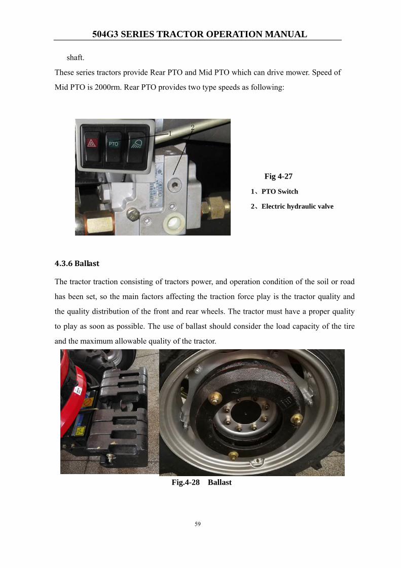
504G3 SERIES TRACTOR OPERATION MANUAL
59
shaft.
These series tractors provide Rear PTO and Mid PTO which can drive mower. Speed of
Mid PTO is 2000rm. Rear PTO provides two type speeds as following:
Fig 4-27
1、PTO Switch
2、Electric hydraulic valve
4.3.6 Ballast
The tractor traction consisting of tractors power, and operation condition of the soil or road
has been set, so the main factors affecting the traction force play is the tractor quality and
the quality distribution of the front and rear wheels. The tractor must have a proper quality
to play as soon as possible. The use of ballast should consider the load capacity of the tire
and the maximum allowable quality of the tractor.
Fig.4-28 Ballast
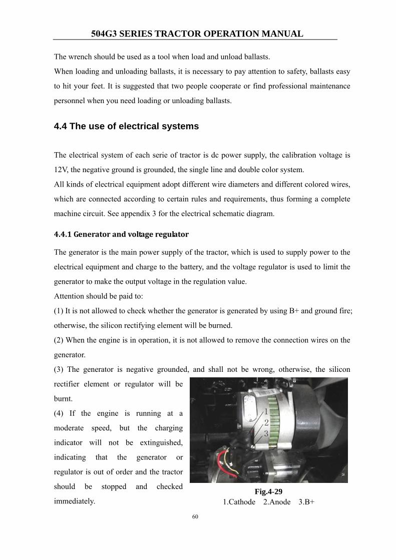
504G3 SERIES TRACTOR OPERATION MANUAL
60
The wrench should be used as a tool when load and unload ballasts.
When loading and unloading ballasts, it is necessary to pay attention to safety, ballasts easy
to hit your feet. It is suggested that two people cooperate or find professional maintenance
personnel when you need loading or unloading ballasts.
4.4 The use of electrical systems
The electrical system of each serie of tractor is dc power supply, the calibration voltage is
12V, the negative ground is grounded, the single line and double color system.
All kinds of electrical equipment adopt different wire diameters and different colored wires,
which are connected according to certain rules and requirements, thus forming a complete
machine circuit. See appendix 3 for the electrical schematic diagram.
4.4.1 Generator and voltage regulator
The generator is the main power supply of the tractor, which is used to supply power to the
electrical equipment and charge to the battery, and the voltage regulator is used to limit the
generator to make the output voltage in the regulation value.
Attention should be paid to:
(1) It is not allowed to check whether the generator is generated by using B+ and ground fire;
otherwise, the silicon rectifying element will be burned.
(2) When the engine is in operation, it is not allowed to remove the connection wires on the
generator.
(3) The generator is negative grounded, and shall not be wrong, otherwise, the silicon
rectifier element or regulator will be
burnt.
(4) If the engine is running at a
moderate speed, but the charging
indicator will not be extinguished,
indicating that the generator or
regulator is out of order and the tractor
should be stopped and checked
immediately.Fig.4-29
1.Cathode 2.Anode 3.B+
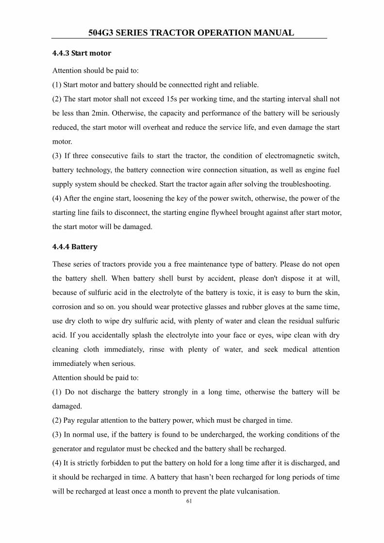
504G3 SERIES TRACTOR OPERATION MANUAL
61
4.4.3 Start motor
Attention should be paid to:
(1) Start motor and battery should be connectted right and reliable.
(2) The start motor shall not exceed 15s per working time, and the starting interval shall not
be less than 2min. Otherwise, the capacity and performance of the battery will be seriously
reduced, the start motor will overheat and reduce the service life, and even damage the start
motor.
(3) If three consecutive fails to start the tractor, the condition of electromagnetic switch,
battery technology, the battery connection wire connection situation, as well as engine fuel
supply system should be checked. Start the tractor again after solving the troubleshooting.
(4) After the engine start, loosening the key of the power switch, otherwise, the power of the
starting line fails to disconnect, the starting engine flywheel brought against after start motor,
the start motor will be damaged.
4.4.4 Battery
These series of tractors provide you a free maintenance type of battery. Please do not open
the battery shell. When battery shell burst by accident, please don't dispose it at will,
because of sulfuric acid in the electrolyte of the battery is toxic, it is easy to burn the skin,
corrosion and so on. you should wear protective glasses and rubber gloves at the same time,
use dry cloth to wipe dry sulfuric acid, with plenty of water and clean the residual sulfuric
acid. If you accidentally splash the electrolyte into your face or eyes, wipe clean with dry
cleaning cloth immediately, rinse with plenty of water, and seek medical attention
immediately when serious.
Attention should be paid to:
(1) Do not discharge the battery strongly in a long time, otherwise the battery will be
damaged.
(2) Pay regular attention to the battery power, which must be charged in time.
(3) In normal use, if the battery is found to be undercharged, the working conditions of the
generator and regulator must be checked and the battery shall be recharged.
(4) It is strictly forbidden to put the battery on hold for a long time after it is discharged, and
it should be recharged in time. A battery that hasn’t been recharged for long periods of time
will be recharged at least once a month to prevent the plate vulcanisation.
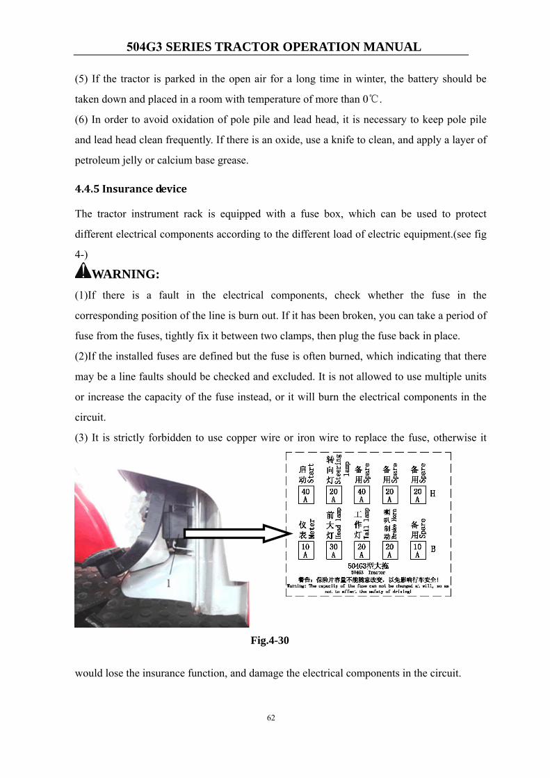
504G3 SERIES TRACTOR OPERATION MANUAL
62
(5) If the tractor is parked in the open air for a long time in winter, the battery should be
taken down and placed in a room with temperature of more than 0℃.
(6) In order to avoid oxidation of pole pile and lead head, it is necessary to keep pole pile
and lead head clean frequently. If there is an oxide, use a knife to clean, and apply a layer of
petroleum jelly or calcium base grease.
4.4.5 Insurance device
The tractor instrument rack is equipped with a fuse box, which can be used to protect
different electrical components according to the different load of electric equipment.(see fig
4-)
WARNING: (1)If there is a fault in the electrical components, check whether the fuse in the
corresponding position of the line is burn out. If it has been broken, you can take a period of
fuse from the fuses, tightly fix it between two clamps, then plug the fuse back in place.
(2)If the installed fuses are defined but the fuse is often burned, which indicating that there
may be a line faults should be checked and excluded. It is not allowed to use multiple units
or increase the capacity of the fuse instead, or it will burn the electrical components in the
circuit.
(3) It is strictly forbidden to use copper wire or iron wire to replace the fuse, otherwise it
would lose the insurance function, and damage the electrical components in the circuit.
Fig.4-30
504G3 SERIES TRACTOR OPERATION MANUAL
63
Chapter 5 Maintenance
Maintain the tractor well can make it work in a good condition, and protect the tractor
from damage, even extend the life.
CAUTION:Maintenance must be operated when the tractor is out of power!
5.1 Oil and lubricants
1、 Oil and lubricants
Position Temperature range Category of oil Remark
Fuel tank
Above 10° C No. 0 light diesel
GB252-87 0° ~10° C No. -10 light diesel
Below -10° C No. -35 light diesel
Gearbox,
front drive axle,
hydraulic system,
and
steering system
All atmospheric
temperature
N100 D transmission
drive & hydraulic
dual-purpose oil GB443-84
Grease fittings All atmospheric
temperature
No. 2 and No. 3 calcic
lubricant GB491-87
Engine sump Summer No.40 diesel engine oil GB5323-85
Winter No.30 diesel engine oil
Clutch release
bearing
All atmospheric
temperature Lithium lubricant GB5671-85
2、 Position
Oil inlet ①engine, ②right place of rear axle housing,
③air pump crankcase, ④left sleeve of front drive axle,
⑤oil case of steering system.
Grease fittings ①Left and right lift arms, ②center link,
③steering cylinder shaft with pin holes ④outer tie rod joints
⑤steering levers and steering arms
504G3 SERIES TRACTOR OPERATION MANUAL
64
⑥front axle arms ⑦left and right front wheel housings
Checking point ①Engine dipstick ②Rear axle housing dipstick,
Dipstick on left half shaft housing of front wheel drive axle③
④Checking plug on the cover of air pump
Oil outlet, ①Bottom of engine sump, ②bottom of rear axle,
④bottom of air pump; ⑤bottom of front drive center housing, and
bootom of left and right retarder housing.
5.2 Periodic Service
According to accumulated working hours, technical maintenance of Knegt series
tractor should be operated every 10h, 50h, 200h, 400h, 800h or 1600h.
Details of the engine’s maintenance can be refered in the manual of engine.
5.2.1 10h maintenance
1、 Engine
① Check the liquid level of engine sump,refill them if they are insufficient,and
make sure the level will be between the middle notch and the topper notch on
the dipstick. Never exceed the topper notch. A new tractor or one haven’t used
for a long time, the level must be checked again after filling and operating for
5 to 10 minutes.
② Fill in enough diesel oil and cooling water.
2、 Chassis
① Check and fasten every external linkage bolts and nuts.
② Use a press rod oil gun at these places: left and right retarder housing.
③ Check and eleminate if there is a leakage of oil, water or air. Clean off the dirt
and mud on the tractor.
④ Check the air pressure of front and rear tires, and inflate if they are insufficient.
3、Air Conditioning Systems
① Check cleaning condenser, and insure the radiating fins clean and expedite.
② Check the drive belt of compressor and engine, and insure it’s not loose.
504G3 SERIES TRACTOR OPERATION MANUAL
65
5.2.2 50h maintenance
1. Engine: After 50 hours of light load working, the oil in the engine sump and
injection pump should be changed, at the same time, change the filter element;
clean the sump, the filter and the filter net with clean diesel.
2. Transmission system: After using for 50 hours, it will be needed to check the free
travel of the clutch pedal, and adjust it if necessary.
3. Accumulator: Check the accumulator of it’s electrical power, charge it if it is not
sufficient.
4. Use a press rod oil gun at these places: Left and right draft links, center link, tie rod
joints, steering cylinder shaft with pin hole.
5. Air Conditioning System: Check the connecting parts and hose, repair or fix the
parts when they are loose; check all the electrical connectors and wires, examine
and repair them if they are deviant.
5.2.3 100h maintenance
1. Engine
① Change the oil in the sump, clean the filter strainer.
② Change engine oil and diesel filter elements, and clean the cavity of filter.
③ Check the tension of fan belt, adjust it if loosed.
④ Check the level of injection pump, refill it if needed.
⑤ Clean the air filter and replace oil (Necessary to perform every time after
working in wet and muddy conditions).
2. Clutch: Check the free travel, adjust it if necessary.
5.2.4 250h maintenance
1. Transmission sysytem:Check the oil level of chassis, refill it if needed.
2. Front axle:Check the toe-in and the bearings of front axle (Two wheel drive),
adjust them is needed.
3. Accumulator: Smear Vaseline or calcic lubricant on the bolts of accumulator.
5.2.5 500h maintenance
1. Check the pressure and fogging quality of the engine oil pump, clean it if necessary.
504G3 SERIES TRACTOR OPERATION MANUAL
66
2. Check and fasten the nuts of engine cylinder head, adjust the valve clearance if
needed.
3. Clean the water scale in the cooling system.
4. Replace the oil of the injection pump.
5.2.6 1000h maintenance
1. Engine
①Check the condition of the valve, repair it if necessary.
②Check the advance angle of injection, make adjustment if necessary.
2. Transmission sysytem:Change the lubricant one time a year at least.
3. Steering system: Check the lubricantion of the steering cylinder, refill if it’s not
sufficient.
4. Check the electrical circuit completely, replaces all of the broken parts.
NOTE:(1) Operate these maintenance according to the schedule will help your tractor work
normally.
(2) The service interval is determined according to the condition of working and your
experience.
(3) Remember that, in any case, it is better to check too much than too little.
(4) If you have any problem during the maintenance, contact your dealer or the after
service.
(5) Air Conditioning System: Refrigerant in air conditioning system will leak naturally,
supply the refrigerant according to the leakage flux.
5.3 Transporting the Machine
5.3.1 Preparing for Road travel
Before transporting the machine, make sure you will be obeying all local rules and laws
of the areas through which the machine will transported.
Confirm that the truck driver knows the clearance height before he drives away. See
Specification Section for machine height figures.
The overall height does not include the truck/trailer height, add the two figures together
504G3 SERIES TRACTOR OPERATION MANUAL
67
for the clearance height.
5.3.2 Before Using the Trailer/Transporter
1.Remove any dirt or debris from the trailer.
2.Check the operation of the park brake.
3.Check the trailer bodywork for signs of damage.
4.Check the tyre pressures are correct.
5.Check the lights are working and are the correct voltage for the towing vehicle.
6.Check the breakaway cable is serviceable
5.3.3 Loading a Machine onto the Transporting Vehicle
The safe transit of the load is the responsibility of the transport contractor and driver.
Any machine, attachments or parts that may move during transit must be adequately
secured.
Before moving the machine onto the trailer, make sure that the trailer and ramp are free
from oil, grease and ice. Remove oil, grease and ice from the machine tyres. Make sure
the machine will not foul on the ramp angle. See Static Dimensions in
SPECIFICATION section for the minimum ground clearance of your machine.
The ramp should be long enough that the angles between the truck or trailer do not
cause the machine components to catch when moving from ramp to truck or trailer. If
loading on or near a slope, position the truck or trailer on the down side of the slope and
the ramps should extend up the slope. This will minimize the ramp angle. The trailer or
truck should be parked as level as possible to facilitate smooth loading of the machine.
Avoid sudden acceleration and deceleration of the unit when loading and unloading the
unit to avoid the machine tipping backward.
Also we can use crane or other equipment to hosit tractor from earth to trailer.
5.3..4 Transporting the Machine
Use a heavy duty trailer or truck to transport the machine. Make sure the trailer or truck
has all of the necessary lighting and markings as required by law.
When transporting the machine, make sure the three point linkage is raised, the park
brake is applied, the wheels have been blocked, the machine has been securely fastened
by cables, chains or ropes, and the trailer has been secured to the towing vehicle with
safety chains.
504G3 SERIES TRACTOR OPERATION MANUAL
68
Driving on a public street or roadway without turn signals, slow moving vehicle
emblem, or reflective markings could lead to accidents causing serious personal injury
or death.
Note:Keep the tractor in a dry place where the tractor is sheltered from the
elements. Cover the tractor。
Note:If you want to use tractor after transporting, you must see 4.2.3 Operating
the Engine.
5.4 Storage
The tractor must be well stored after working or when it will not be used for a long time,
so it can be protect from corrosion and deterioration.
5.4.1 Preparation for Storage
1. According to the manual of engine to store and maintain the diesel engine.
2. Thoroughly clean the tractor, especially the body parts, brush protective coating on
the painted metal parts, store the tractor under cover and in dry and well-ventilated
places.
3. Brush anti-rust paint on the unpainted metal parts.
4. Ensure that all controls are in neutral or off position (including the electrical switch
and the parking brake).
5. Do not leave the key in the electric switch.
6. Fill the fuel tank to the topper level.
7. Remove battery, clean battery top and coat terminal clamps and leads with Vaseline
or calcic lubricant, subsequently store the battery in dim and ventilated places with
temperature remaining above 0℃.
8. Put stands or other supports under the front axle/front wheel drive axle and rear
axle in order to bear the tractor weight. With the tractor being propped up, it is
advisable to deflate tires.
9. Drain away thoroughly the water in radiator for passing away in the winter season.
10. Cover the tractor with waterproof canvas to prevent from dust or water.
Refer to the manual of engine for the storage of engine.
504G3 SERIES TRACTOR OPERATION MANUAL
69
5.4.2 Tractor maintenance during storage
1. During the storage, check and protect the tractor from rust, corrosion, deterioration
and deformation every month.
2. Start the tractor every 3 month, and run it at a low speed for 20 to 30 minutes,
check if there is somewhere abnormal. Before start the engine, follow the request to
add in coolant, diesel, oil and lubricant.
3. Check the condition of the accumulator. It’s better to charge the battery every
month for it will discharge when not be used.
5.4.3 Preparation after Storage
1. Remove the waterproof canvas, clean the tractor.
2. According to the request to fill with coolant, diesel, oil and lubricant.
3. Check the tire pressure and charge if it is not sufficient.
4. Check and charge the accumulator.
5. Check and tighten every external bolts and nuts, especially the bolts on the rear
wheel hub, flywheel housing and clutch housing and so on. Check the condition of
the pipeline and electrical facility, clear the problem if find.
6. Operate the tractor as chapter 4 required, if there is any problem, clear it
immediately.
Important:Refer to manual of engine to get information about the engine’s
moving from storage.
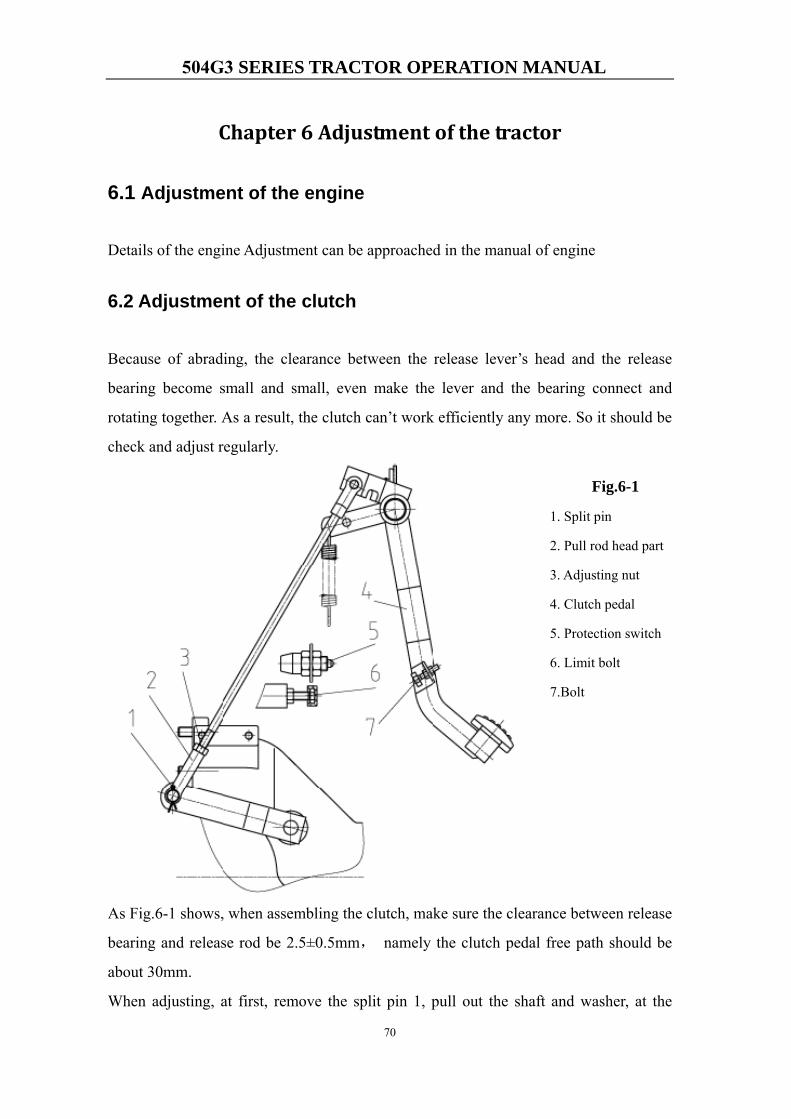
504G3 SERIES TRACTOR OPERATION MANUAL
70
Chapter 6 Adjustment of the tractor
6.1 Adjustment of the engine
Details of the engine Adjustment can be approached in the manual of engine
6.2 Adjustment of the clutch
Because of abrading, the clearance between the release lever’s head and the release
bearing become small and small, even make the lever and the bearing connect and
rotating together. As a result, the clutch can’t work efficiently any more. So it should be
check and adjust regularly.
As Fig.6-1 shows, when assembling the clutch, make sure the clearance between release
bearing and release rod be 2.5±0.5mm, namely the clutch pedal free path should be
about 30mm.
When adjusting, at first, remove the split pin 1, pull out the shaft and washer, at the
Fig.6-1
1. Split pin
2. Pull rod head part
3. Adjusting nut
4. Clutch pedal
5. Protection switch
6. Limit bolt
7.Bolt
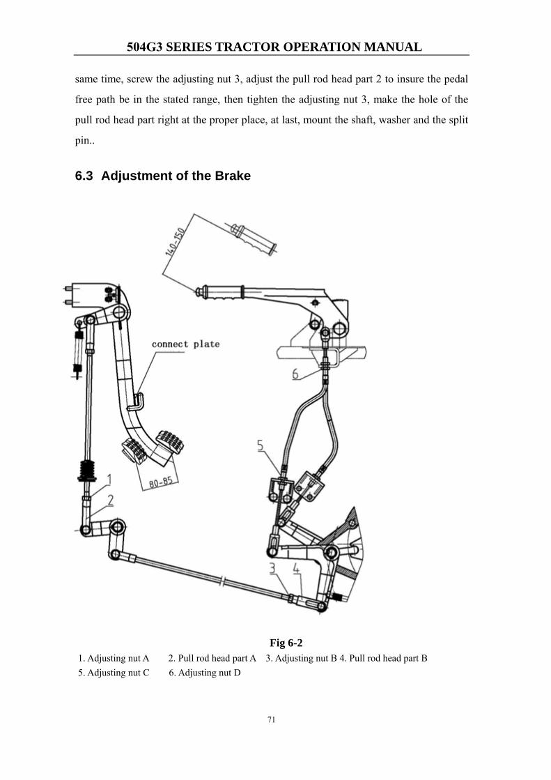
504G3 SERIES TRACTOR OPERATION MANUAL
71
same time, screw the adjusting nut 3, adjust the pull rod head part 2 to insure the pedal
free path be in the stated range, then tighten the adjusting nut 3, make the hole of the
pull rod head part right at the proper place, at last, mount the shaft, washer and the split
pin..
6.3 Adjustment of the Brake
Fig 6-2 1. Adjusting nut A 2. Pull rod head part A 3. Adjusting nut B 4. Pull rod head part B5. Adjusting nut C 6. Adjusting nut D
504G3 SERIES TRACTOR OPERATION MANUAL
72
The free path of the brake pedal is between 80 and 85mm. During the usage, as the
driven disk abrading, the free path exceeds the regular range, even influence braking, so
it must be adjusted.
6.3.1 Adjustment of service braking system
Before regulating, disconnect the connect plate, and adjust the free path of every pedal.
As Fig.6-2 shows, adjust piece 1 and 2 or (with) piece 3 and 4. Here gives the way of
how to adjust piece 1 and 2 as follows.
At first, bring down the split pin and shaft, then screw the nut 1, rotating the pull rod
head part A to regulate the length of the pull rod, so make the free path of every pedal
be about the same and between 80 and 85mm, after that, fasten the nut.
After adjusting the pedal, the tractor must be test at the highest speed on the dry flat,
and then try to brake urgently. After that, check the tire print lengths. Make sure the
diffence between left one and right one doesn’t exceed 400mm. If it fails to reach the
request, adjust again.
6.3.2 Adjustment of parking braking system
Before regulating, bring down the split pin and shaft,then screw the nut 5 or 6,making
the clevis of flexible line fit with the brake rocker hole, and then fasten the nuts.
After adjusting the flexible line,the tractor must immovable on the ramp when using the
parking braking system.If the tractor have a remotion,it’s must be adjusted again
6.4 Adjustment of the Chassis
In order to ensure the reliable of the main drive, the spiral bevel pinion and the spiral
crown gear should be a matched pair when assembling, at the same time, they should be
adjusted correctly to approach the right meshing zone. The position must be adjusted
when the gears or the bearings are abraded.
6.4.1 Adjustment of the pre-stress of the spiral bevel pinion bearings
The two bearings 2 and 5 on the shaft should be pre-stressed (Fig.6-3). The pressure is
adjusted by screw the locking nut 1. It has been adjusted to the proper pressure by the
factory, and will not be adjusted again only when the bearings 2 and 5 should be
504G3 SERIES TRACTOR OPERATION MANUAL
73
changed or this part needs a repair. When adjusting, screw down the bolts 3 (totally 4),
get down the assemblage of spiral bevel pinion, then clamp the assemblage to a table
vice or other work platform. Loose the locking nut 1, and then knock the spiral bevel
pinion and the bearings down. Change the bearings and locking nut. Make sure there is
a torque of 1.5 to 2.5Nm when rotating the pinion. If no equipment or tool can be used
to measure the torque, ask somebody who is experienced for help. At last, lock the
locking nut.
6.4.2 Adjustment of the spiral bevel pinion and spiral bevel crown gear
Correct meshing zone and right clearance between tooths of the drive pinion and crown
gear can influence the life of the main drive and the noise (Fig.6-3). Because of
abrasion of the gears and bearings, the clearance increases. As a result, the gears can not
work in the correct meshing zone. There is no necessary to adjust only when it effect
the gears to work normally or the bearings and the bevel gears need to be replaced or
the assemblage needs to be repaired. (The adjusting needs to be done after the bearings
have been fastened.)
1. Check the clearance between the teeth
Make sure the clearance of the pinion and crown gears at the stated range. Only when
the clearance is large enough, it should be adjusted.
When adjusting, put a lead piece between the teeth of pinion and crown gears. The lead
piece will be pushed to transform. Then measure the thickness of lead piece near the big
end. The proper clearance changes from 0.16 to 0.32mm. Measure it for 3 times and at
3 point which equally at the circle. The difference between them should be less than
0.1mm. If it failed to reach the request, adjust the adjusting nuts (9) and (13).
2. Checking the meshing zone
Through measuring the meshing zone, we can know if the gears work normally. The
meshing zone can be measured by smear test , painting the crown gear teeth with some
colors such as red lead or Prussian blue. The standard meshing zone should be in the
middle of all the teeth face and deflecting to small end of teeth slightly. It’s length at
least equal to 55% of the width, and its height equal to at least 55% of the tooth’s height.
If the meshing zone doesn’t accord with the proper position, the bevel gears should be
adjusted.
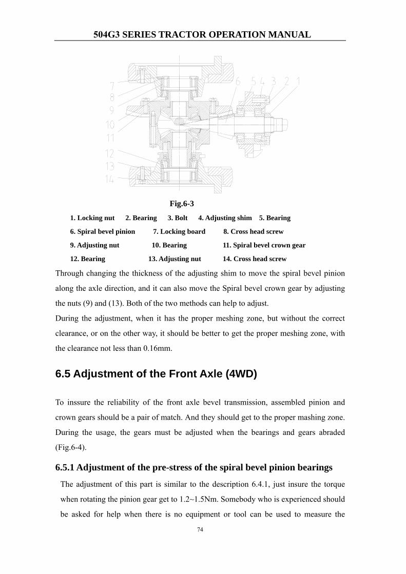
504G3 SERIES TRACTOR OPERATION MANUAL
74
Fig.6-3
1. Locking nut 2. Bearing 3. Bolt 4. Adjusting shim 5. Bearing
6. Spiral bevel pinion 7. Locking board 8. Cross head screw
9. Adjusting nut 10. Bearing 11. Spiral bevel crown gear
12. Bearing 13. Adjusting nut 14. Cross head screw
Through changing the thickness of the adjusting shim to move the spiral bevel pinion
along the axle direction, and it can also move the Spiral bevel crown gear by adjusting
the nuts (9) and (13). Both of the two methods can help to adjust.
During the adjustment, when it has the proper meshing zone, but without the correct
clearance, or on the other way, it should be better to get the proper meshing zone, with
the clearance not less than 0.16mm.
6.5 Adjustment of the Front Axle (4WD)
To inssure the reliability of the front axle bevel transmission, assembled pinion and
crown gears should be a pair of match. And they should get to the proper mashing zone.
During the usage, the gears must be adjusted when the bearings and gears abraded
(Fig.6-4).
6.5.1 Adjustment of the pre-stress of the spiral bevel pinion bearings
The adjustment of this part is similar to the description 6.4.1, just insure the torque
when rotating the pinion gear get to 1.2~1.5Nm. Somebody who is experienced should
be asked for help when there is no equipment or tool can be used to measure the
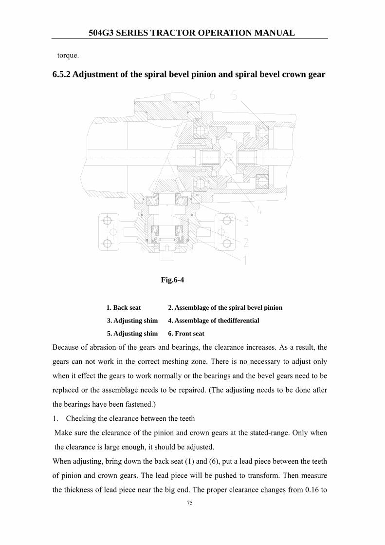
504G3 SERIES TRACTOR OPERATION MANUAL
75
torque.
6.5.2 Adjustment of the spiral bevel pinion and spiral bevel crown gear
Fig.6-4
1. Back seat 2. Assemblage of the spiral bevel pinion
3. Adjusting shim 4. Assemblage of thedifferential
5. Adjusting shim 6. Front seat
Because of abrasion of the gears and bearings, the clearance increases. As a result, the
gears can not work in the correct meshing zone. There is no necessary to adjust only
when it effect the gears to work normally or the bearings and the bevel gears need to be
replaced or the assemblage needs to be repaired. (The adjusting needs to be done after
the bearings have been fastened.)
1. Checking the clearance between the teeth
Make sure the clearance of the pinion and crown gears at the stated-range. Only when
the clearance is large enough, it should be adjusted.
When adjusting, bring down the back seat (1) and (6), put a lead piece between the teeth
of pinion and crown gears. The lead piece will be pushed to transform. Then measure
the thickness of lead piece near the big end. The proper clearance changes from 0.16 to
504G3 SERIES TRACTOR OPERATION MANUAL
76
0.32mm. Measure it for 3 times and at 3 point which equally at the circle. The
difference between them should be less than 0.1mm. If it failed to reach the request,
adjust the thickness of adjusting shim (5). At last, put all of the components on.
2. Checking the meshing zone
The meshing zone can be measured by smear test, painting the crown gear teeth with
some colors such as red lead or Prussian blue. The standard meshing zone should be in
the middle of all the teeth face and deflecting to small end of teeth slightly. It’s length at
least equal to 55% of the width, and it’s height equal to at least 55% of the tooth’s
height. If the meshing zone doesn’t accord with the proper position, adjust the thickness
of the shim (3) and (5).
During the adjustment, when it has the proper meshing zone, but without the correct
clearance, or on the other way, it should be better to get the proper meshing zone, with
the clearance not less than 0.2mm.
6.5.3 Adjustment of front axle final transmission
There are two couples of gears in the front axle final transmission (As Fig.6-5 shows,
one couple is piece 1, 2 and another is piece 4, 5). They have been adjusted in the
factory, generally, there is no need to adjust them by the users unless replacing the
bearings and gears or do some repairs. The two couples have the same way to be adjust,
here will give the example.
Before adjusting, bring down the tire, raise the front axle. Remove the steering arm (8)
and upper bearing cover (7), adjust the clearance between drive pinion (4) and drive
pinion (5) through changing the thickness of adjusting shim (6).
Generally, the clearance is between 0.16 to 0.3mm. After the adjustment, reinstall all of
the components. It’s better to ask someone professional to finish the work.
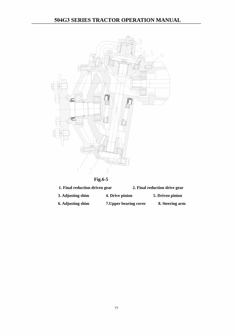
504G3 SERIES TRACTOR OPERATION MANUAL
77
Fig.6-5
1. Final reduction driven gear 2. Final reduction drive gear
3. Adjusting shim 4. Drive pinion 5. Driven pinion
6. Adjusting shim 7.Upper bearing cover 8. Steering arm
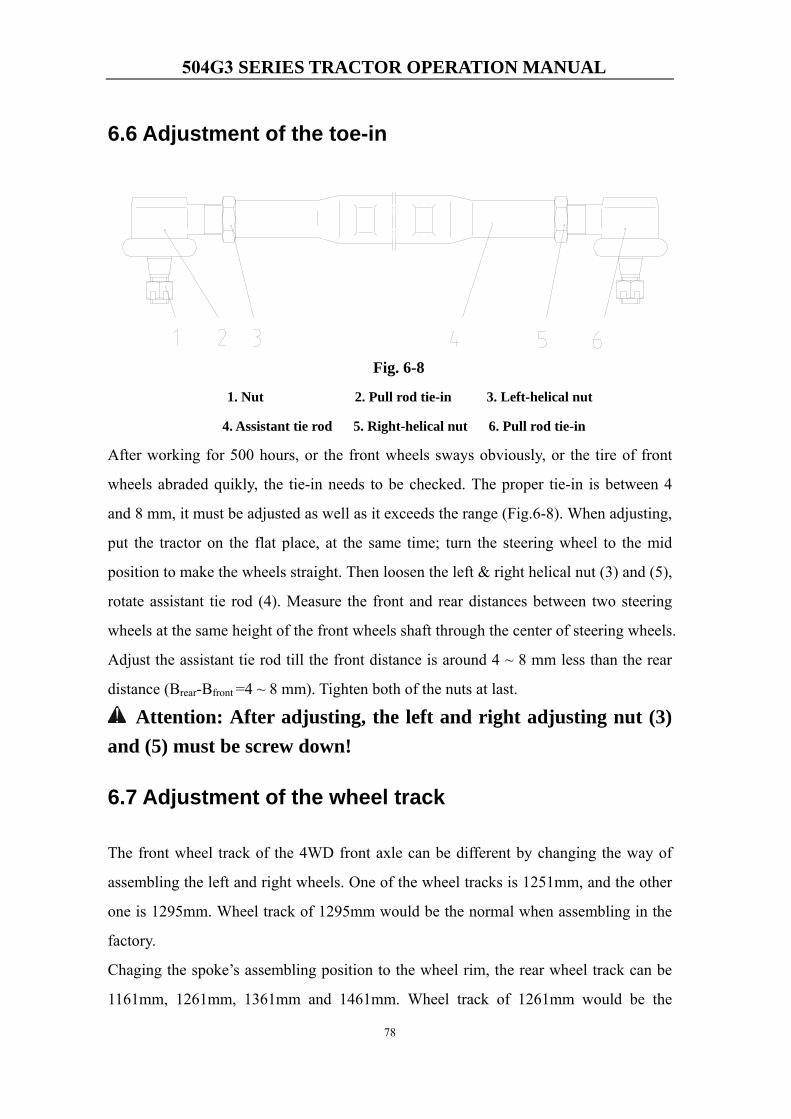
504G3 SERIES TRACTOR OPERATION MANUAL
78
6.6 Adjustment of the toe-in
Fig. 6-8
1. Nut 2. Pull rod tie-in 3. Left-helical nut
4. Assistant tie rod 5. Right-helical nut 6. Pull rod tie-in
After working for 500 hours, or the front wheels sways obviously, or the tire of front
wheels abraded quikly, the tie-in needs to be checked. The proper tie-in is between 4
and 8 mm, it must be adjusted as well as it exceeds the range (Fig.6-8). When adjusting,
put the tractor on the flat place, at the same time; turn the steering wheel to the mid
position to make the wheels straight. Then loosen the left & right helical nut (3) and (5),
rotate assistant tie rod (4). Measure the front and rear distances between two steering
wheels at the same height of the front wheels shaft through the center of steering wheels.
Adjust the assistant tie rod till the front distance is around 4 ~ 8 mm less than the rear
distance (Brear-Bfront =4 ~ 8 mm). Tighten both of the nuts at last.
Attention: After adjusting, the left and right adjusting nut (3) and (5) must be screw down!
6.7 Adjustment of the wheel track
The front wheel track of the 4WD front axle can be different by changing the way of
assembling the left and right wheels. One of the wheel tracks is 1251mm, and the other
one is 1295mm. Wheel track of 1295mm would be the normal when assembling in the
factory.
Chaging the spoke’s assembling position to the wheel rim, the rear wheel track can be
1161mm, 1261mm, 1361mm and 1461mm. Wheel track of 1261mm would be the
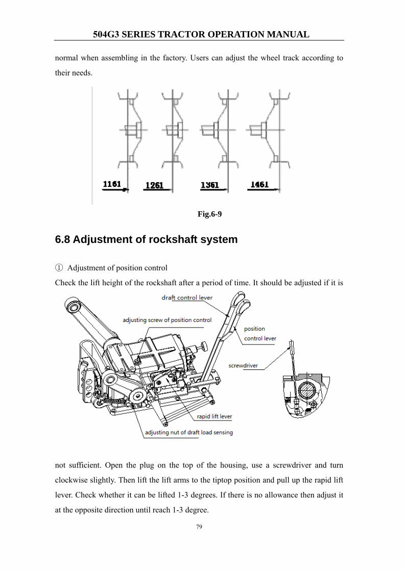
504G3 SERIES TRACTOR OPERATION MANUAL
79
normal when assembling in the factory. Users can adjust the wheel track according to
their needs.
Fig.6-9
6.8 Adjustment of rockshaft system
① Adjustment of position control
Check the lift height of the rockshaft after a period of time. It should be adjusted if it is
not sufficient. Open the plug on the top of the housing, use a screwdriver and turn
clockwise slightly. Then lift the lift arms to the tiptop position and pull up the rapid lift
lever. Check whether it can be lifted 1-3 degrees. If there is no allowance then adjust it
at the opposite direction until reach 1-3 degree.

504G3 SERIES TRACTOR OPERATION MANUAL
80
②Adjustment of draft control
Unpack the implement and push the position control lever to the end as well as the draft
control lever. Put down the lift links to the ground. Pull the draft control lever until the
lift arms tend to lift. Now the position of the draft control lever should be 5 to 10
degrees to the back end. If it’s bigger the 10 degrees, tighten the adjust nut of draft load
sensing slightly.
NOTE: if the degree is more than 10°, the draft control lever cannot be pushed to the
maximum position or the desired depth cannot be achieve when use both draft control
lever and position control lever.
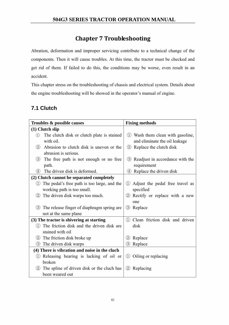
504G3 SERIES TRACTOR OPERATION MANUAL
81
Chapter 7 Troubleshooting
Abration, deformation and improper servicing contribute to a technical change of the
components. Then it will cause troubles. At this time, the tractor must be checked and
get rid of them. If failed to do this, the conditions may be worse, even result in an
accident.
This chapter stress on the troubleshooting of chassis and electrical system. Details about
the engine troubleshooting will be showed in the operator’s manual of engine.
7.1 Clutch
Troubles & possible causes Fixing methods (1) Clutch slip
① The clutch disk or clutch plate is stainedwith oil.
② Abrasion to clutch disk is uneven or theabrasion is serious.
③ The free path is not enough or no freepath.
④ The driven disk is deformed.
① Wash them clean with gasoline,and eliminate the oil leakage
② Replace the clutch disk
③ Readjust in accordance with therequirement
④ Replace the driven disk(2) Clutch cannot be separated completely① The pedal’s free path is too large, and the
working path is too small.② The driven disk warps too much.
③ The release finger of diaphragm spring arenot at the same plane
① Adjust the pedal free travel asspecified
② Rectify or replace with a newone
③ Replace
(3) The tractor is shivering at starting① The friction disk and the driven disk are
stained with oil② The friction disk broke up③ The driven disk warps
① Clean friction disk and drivendisk
② Replace③ Replace
(4) There is vibration and noise in the cluch① Releasing bearing is lacking of oil or
broken② The spline of driven disk or the cluch has
been weared out
① Oiling or replacing
② Replacing
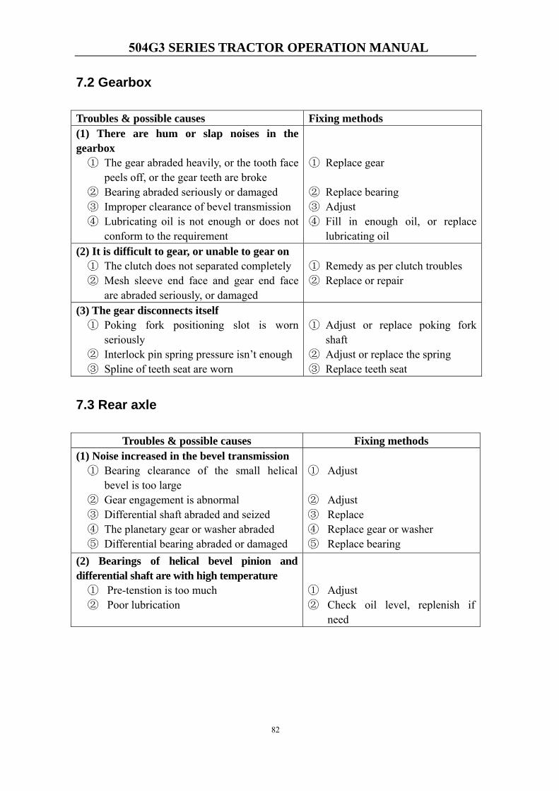
504G3 SERIES TRACTOR OPERATION MANUAL
82
7.2 Gearbox
Troubles & possible causes Fixing methods (1) There are hum or slap noises in thegearbox① The gear abraded heavily, or the tooth face
peels off, or the gear teeth are broke② Bearing abraded seriously or damaged③ Improper clearance of bevel transmission④ Lubricating oil is not enough or does not
conform to the requirement
① Replace gear
② Replace bearing③ Adjust④ Fill in enough oil, or replace
lubricating oil(2) It is difficult to gear, or unable to gear on① The clutch does not separated completely② Mesh sleeve end face and gear end face
are abraded seriously, or damaged
① Remedy as per clutch troubles② Replace or repair
(3) The gear disconnects itself① Poking fork positioning slot is worn
seriously② Interlock pin spring pressure isn’t enough③ Spline of teeth seat are worn
① Adjust or replace poking forkshaft
② Adjust or replace the spring③ Replace teeth seat
7.3 Rear axle
Troubles & possible causes Fixing methods (1) Noise increased in the bevel transmission① Bearing clearance of the small helical
bevel is too large② Gear engagement is abnormal③ Differential shaft abraded and seized④ The planetary gear or washer abraded⑤ Differential bearing abraded or damaged
① Adjust
② Adjust③ Replace④ Replace gear or washer⑤ Replace bearing
(2) Bearings of helical bevel pinion anddifferential shaft are with high temperature① Pre-tenstion is too much② Poor lubrication
① Adjust② Check oil level, replenish if
need
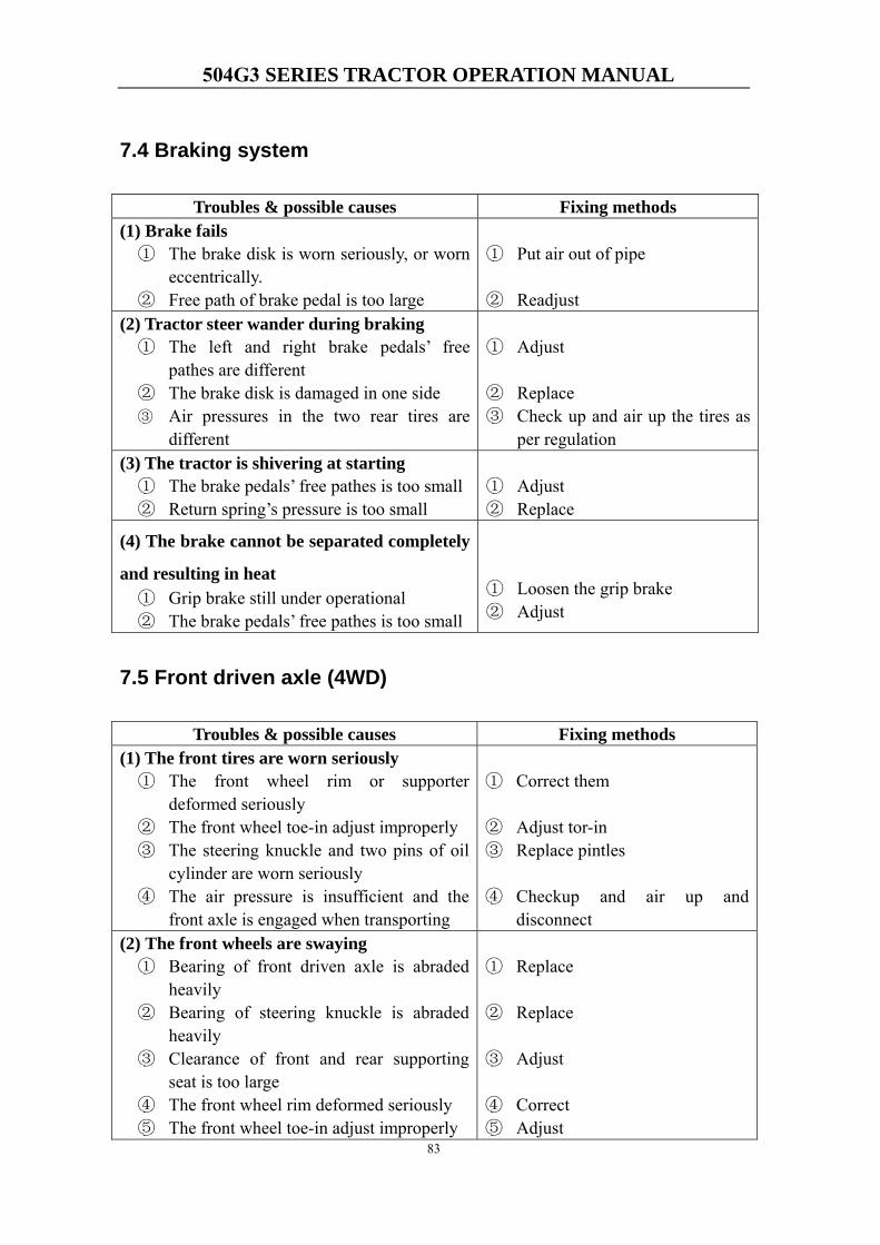
504G3 SERIES TRACTOR OPERATION MANUAL
83
7.4 Braking system
Troubles & possible causes Fixing methods (1) Brake fails① The brake disk is worn seriously, or worn
eccentrically.② Free path of brake pedal is too large
① Put air out of pipe
② Readjust(2) Tractor steer wander during braking① The left and right brake pedals’ free
pathes are different② The brake disk is damaged in one side③ Air pressures in the two rear tires are
different
① Adjust
② Replace③ Check up and air up the tires as
per regulation(3) The tractor is shivering at starting① The brake pedals’ free pathes is too small② Return spring’s pressure is too small
① Adjust② Replace
(4) The brake cannot be separated completely
and resulting in heat① Grip brake still under operational② The brake pedals’ free pathes is too small
① Loosen the grip brake② Adjust
7.5 Front driven axle (4WD)
Troubles & possible causes Fixing methods (1) The front tires are worn seriously① The front wheel rim or supporter
deformed seriously② The front wheel toe-in adjust improperly③ The steering knuckle and two pins of oil
cylinder are worn seriously④ The air pressure is insufficient and the
front axle is engaged when transporting
① Correct them
② Adjust tor-in③ Replace pintles
④ Checkup and air up anddisconnect
(2) The front wheels are swaying① Bearing of front driven axle is abraded
heavily② Bearing of steering knuckle is abraded
heavily③ Clearance of front and rear supporting
seat is too large④ The front wheel rim deformed seriously⑤ The front wheel toe-in adjust improperly
① Replace
② Replace
③ Adjust
④ Correct⑤ Adjust
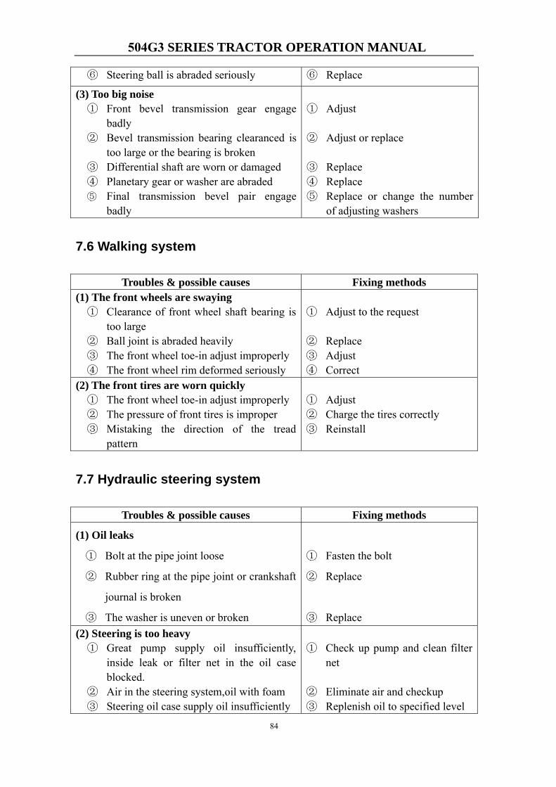
504G3 SERIES TRACTOR OPERATION MANUAL
84
⑥ Steering ball is abraded seriously ⑥ Replace
(3) Too big noise① Front bevel transmission gear engage
badly② Bevel transmission bearing clearanced is
too large or the bearing is broken③ Differential shaft are worn or damaged④ Planetary gear or washer are abraded⑤ Final transmission bevel pair engage
badly
① Adjust
② Adjust or replace
③ Replace④ Replace⑤ Replace or change the number
of adjusting washers
7.6 Walking system
Troubles & possible causes Fixing methods (1) The front wheels are swaying① Clearance of front wheel shaft bearing is
too large② Ball joint is abraded heavily③ The front wheel toe-in adjust improperly④ The front wheel rim deformed seriously
① Adjust to the request
② Replace③ Adjust④ Correct
(2) The front tires are worn quickly① The front wheel toe-in adjust improperly② The pressure of front tires is improper③ Mistaking the direction of the tread
pattern
① Adjust② Charge the tires correctly③ Reinstall
7.7 Hydraulic steering system
Troubles & possible causes Fixing methods
(1) Oil leaks
① Bolt at the pipe joint loose
② Rubber ring at the pipe joint or crankshaft
journal is broken
③ The washer is uneven or broken
① Fasten the bolt
② Replace
③ Replace(2) Steering is too heavy① Great pump supply oil insufficiently,
inside leak or filter net in the oil caseblocked.
② Air in the steering system,oil with foam③ Steering oil case supply oil insufficiently
① Check up pump and clean filternet
② Eliminate air and checkup③ Replenish oil to specified level
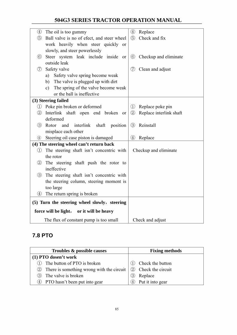
504G3 SERIES TRACTOR OPERATION MANUAL
85
④ The oil is too gummy⑤ Ball valve is no of efect, and steer wheel
work heavily when steer quickly orslowly, and steer powerlessly
⑥ Steer system leak include inside oroutside leak
⑦ Safety valvea) Safety valve spring become weakb) The valve is plugged up with dirtc) The spring of the valve become weak
or the ball is ineffective
④ Replace⑤ Check and fix
⑥ Checkup and eliminate
⑦ Clean and adjust
(3) Steering failed① Poke pin broken or deformed② Interlink shaft open end broken or
deformed③ Rotor and interlink shaft position
misplace each other④ Steering oil case piston is damaged
① Replace poke pin② Replace interlink shaft
③ Reinstall
④ Replace(4) The steering wheel can’t return back① The steering shaft isn’t concentric with
the rotor② The steering shaft push the rotor to
ineffective③ The steering shaft isn’t concentric with
the steering column, steering moment istoo large
④ The return spring is broken
Checkup and eliminate
(5) Turn the steering wheel slowly,steering
force will be light, or it will be heavy
The flux of constant pump is too small Check and adjust
7.8 PTO
Troubles & possible causes Fixing methods (1) PTO dosen’t work① The button of PTO is broken② There is something wrong with the circuit③ The valve is broken④ PTO hasn’t been put into gear
① Check the button② Check the circuit③ Replace④ Put it into gear
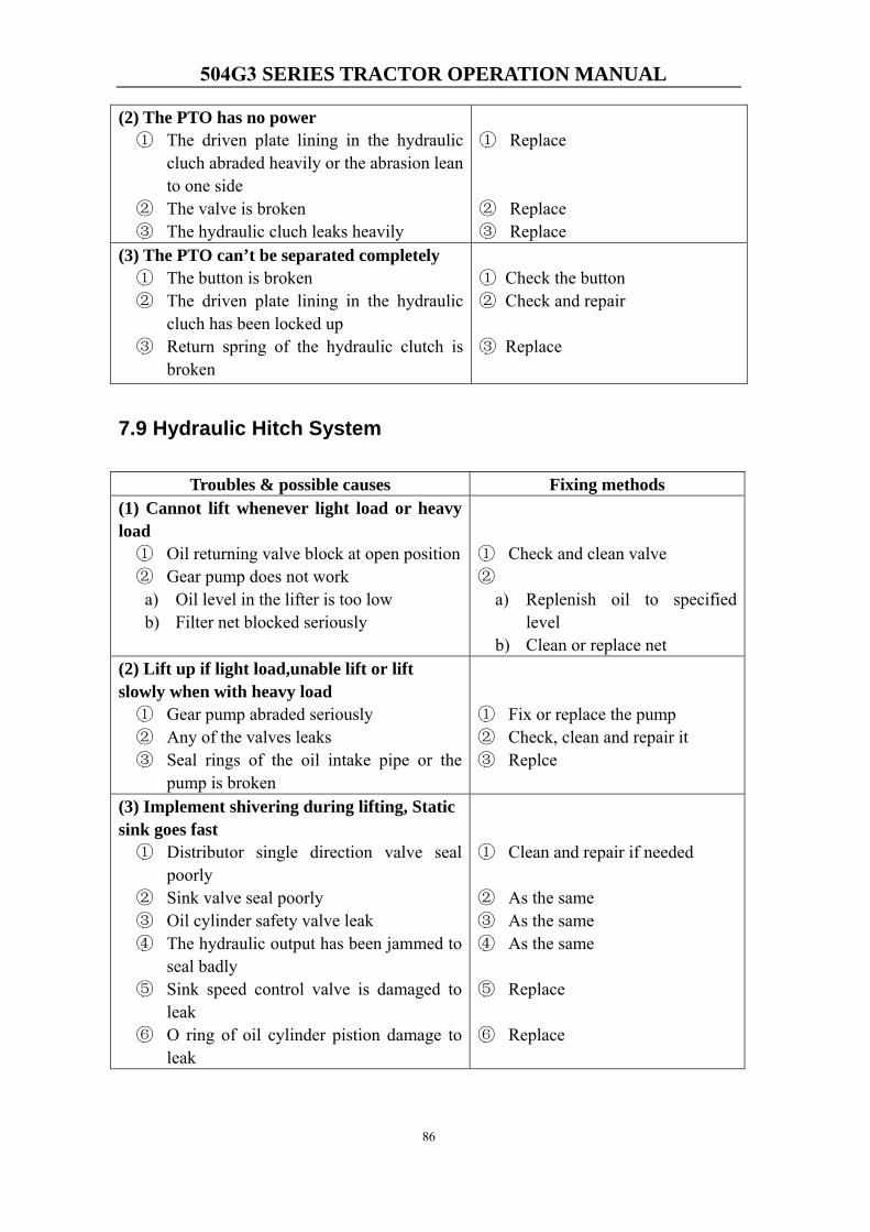
504G3 SERIES TRACTOR OPERATION MANUAL
86
(2) The PTO has no power① The driven plate lining in the hydraulic
cluch abraded heavily or the abrasion leanto one side
② The valve is broken③ The hydraulic cluch leaks heavily
① Replace
② Replace③ Replace
(3) The PTO can’t be separated completely① The button is broken② The driven plate lining in the hydraulic
cluch has been locked up③ Return spring of the hydraulic clutch is
broken
① Check the button② Check and repair
③ Replace
7.9 Hydraulic Hitch System
Troubles & possible causes Fixing methods (1) Cannot lift whenever light load or heavyload① Oil returning valve block at open position② Gear pump does not work
a) Oil level in the lifter is too lowb) Filter net blocked seriously
① Check and clean valve②
a) Replenish oil to specifiedlevel
b) Clean or replace net(2) Lift up if light load,unable lift or liftslowly when with heavy load① Gear pump abraded seriously② Any of the valves leaks③ Seal rings of the oil intake pipe or the
pump is broken
① Fix or replace the pump② Check, clean and repair it③ Replce
(3) Implement shivering during lifting, Staticsink goes fast① Distributor single direction valve seal
poorly② Sink valve seal poorly③ Oil cylinder safety valve leak④ The hydraulic output has been jammed to
seal badly⑤ Sink speed control valve is damaged to
leak⑥ O ring of oil cylinder pistion damage to
leak
① Clean and repair if needed
② As the same③ As the same④ As the same
⑤ Replace
⑥ Replace
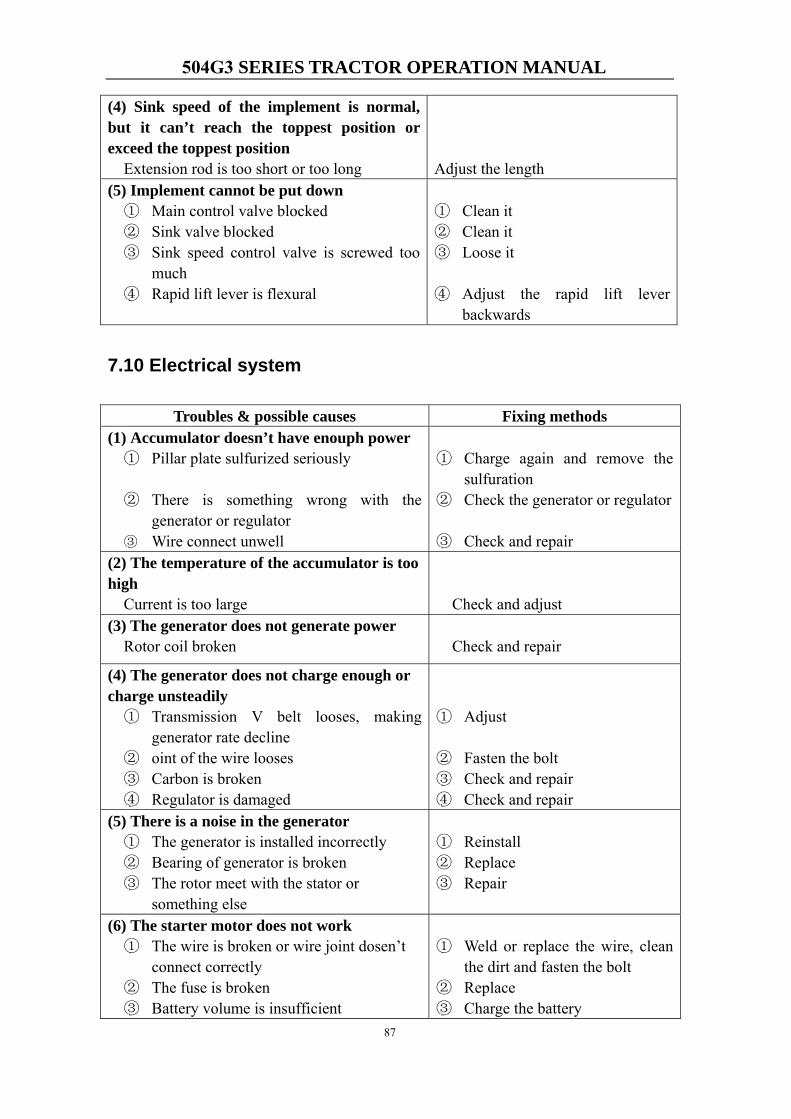
504G3 SERIES TRACTOR OPERATION MANUAL
87
(4) Sink speed of the implement is normal,but it can’t reach the toppest position orexceed the toppest position
Extension rod is too short or too long Adjust the length (5) Implement cannot be put down① Main control valve blocked② Sink valve blocked③ Sink speed control valve is screwed too
much④ Rapid lift lever is flexural
① Clean it② Clean it③ Loose it
④ Adjust the rapid lift leverbackwards
7.10 Electrical system
Troubles & possible causes Fixing methods (1) Accumulator doesn’t have enouph power① Pillar plate sulfurized seriously
② There is something wrong with thegenerator or regulator
③ Wire connect unwell
① Charge again and remove thesulfuration
② Check the generator or regulator
③ Check and repair(2) The temperature of the accumulator is toohigh Current is too large Check and adjust (3) The generator does not generate power
Rotor coil broken Check and repair
(4) The generator does not charge enough orcharge unsteadily① Transmission V belt looses, making
generator rate decline② oint of the wire looses③ Carbon is broken④ Regulator is damaged
① Adjust
② Fasten the bolt③ Check and repair④ Check and repair
(5) There is a noise in the generator① The generator is installed incorrectly② Bearing of generator is broken③ The rotor meet with the stator or
something else
① Reinstall② Replace③ Repair
(6) The starter motor does not work① The wire is broken or wire joint dosen’t
connect correctly② The fuse is broken③ Battery volume is insufficient
① Weld or replace the wire, cleanthe dirt and fasten the bolt
② Replace③ Charge the battery
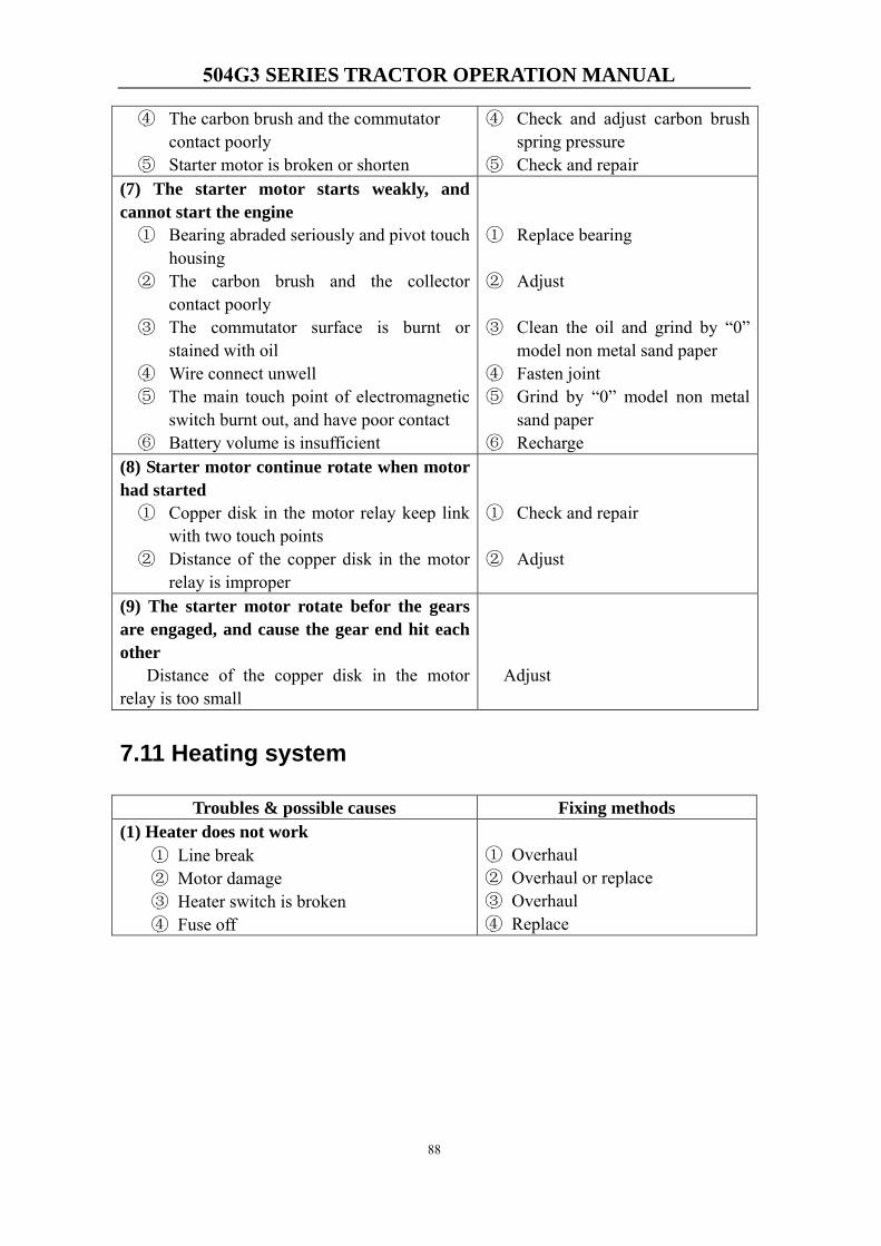
504G3 SERIES TRACTOR OPERATION MANUAL
88
④ The carbon brush and the commutatorcontact poorly
⑤ Starter motor is broken or shorten
④ Check and adjust carbon brushspring pressure
⑤ Check and repair(7) The starter motor starts weakly, andcannot start the engine① Bearing abraded seriously and pivot touch
housing② The carbon brush and the collector
contact poorly③ The commutator surface is burnt or
stained with oil④ Wire connect unwell⑤ The main touch point of electromagnetic
switch burnt out, and have poor contact⑥ Battery volume is insufficient
① Replace bearing
② Adjust
③ Clean the oil and grind by “0”model non metal sand paper
④ Fasten joint⑤ Grind by “0” model non metal
sand paper⑥ Recharge
(8) Starter motor continue rotate when motorhad started① Copper disk in the motor relay keep link
with two touch points② Distance of the copper disk in the motor
relay is improper
① Check and repair
② Adjust
(9) The starter motor rotate befor the gearsare engaged, and cause the gear end hit eachother
Distance of the copper disk in the motor relay is too small
Adjust
7.11 Heating system
Troubles & possible causes Fixing methods (1) Heater does not work
① Line break② Motor damage③ Heater switch is broken④ Fuse off
① Overhaul② Overhaul or replace③ Overhaul④ Replace

504G3 SERIES TRACTOR OPERATION MANUAL
89
Chapter 8 Appendix
Appendix 1 Standards and Regulations
NO.Standard
NO.Name of standard
1 Q/3204BYN008 DF25-45G2 系列轮式拖拉机
DF25-45G2 series wheeled tractor
2 (EU)No 167/2013 On the approval and market surveillance of agricultural and forestry vehicles
3 (EU)No 1322/2014
supplementing and amending Regulation (EU) No 167/2013 of the European Parliament
and of the Council with regard to vehicle construction and general requirements for the
approval of agricultural and forestry vehicles
4 (EU)2015/68
supplementing Regulation (EU) No 167/2013 of the European Parliament and of the
Council with regard to vehicle braking requirements for the approval of agricultural and
forestry vehicles
5 (EU)2015/96
supplementing Regulation (EU) No 167/2013 of the European Parliament and of the
Council as regards environmental and propulsion unit performance requirements of
agricultural and forestry vehicles
6 (EU)2015/208
supplementing Regulation (EU) No 167/2013 of the European Parliament and of the
Council with regard to vehicle functional safety requirements for the approval of
agricultural and forestry vehicles
7 (EU)2015/504
implementing Regulation (EU) No 167/2013 of the European Parliament and of the
Council with regard to the administrative requirements for the approval and market
surveillance of agricultural and forestry vehicles
8 GB10395.1-2001
农林拖拉机和机械 安全技术要求 第一部分 总则
Tractors and machinery for agriculture and forestry--Technical means for ensuring
safety--Part 1:General
9 GB15369-2004
农林拖拉机和机械 安全技术要求 第 3 部分: 拖拉机
Tractors and machineryfor agriculture and forestry--Technical means for ensuring
safety--Part 3:Tractors
10 GB/T15370-2004 农业轮式和履带拖拉机 通用技术条件
General requirement of agriculturalwheeled tractors and crawler tractors
11 GB16151.1-2008 农业机械运行安全技术条件 第 1 部分:拖拉机
Technical requirements of operating safety for agricultural machinery - Part 1: Tractor
12 JB/T6702-2004 拖拉机产品图样及设计文件编号规则
code rule for tractor part drawings and designing files

504G3 SERIES TRACTOR OPERATION MANUAL
90
Appendix 2 Tightening Torque Table of Main Bolts and Nuts
No. Installation position specifications Tightening torque(N·m)
Intensity grade
1 Connecting bolt for engine and clutchhousing M10 41~51 Grade 8.8
2
Connecting bolt and screw for clutch housing and gearbox housing, gearbox housing and rear axle housing, rear axle housing and lifter housing
M12 73~89 Grade 8.8
3 Connecting bolt and screw for final transmission housing and gearbox housing
M12 73~89 Grade 8.8
4 Connecting bolt for differential housing M10 41~51 Grade 8.8
5 Connecting bolt for spiral bevel gear and differential housing M10×1 46~56 Grade 8.8
6 Connecting bolt for bearing seat of spiral bevel pinion and rear axle housing
M12 60-70 Grade 8.8
7 Connecting bolt for differential gear shaft housing and rear axle housing
M12 73~89 Grade 8.8
8 Bolt for steering box M14 120~140 Grade 8.8
9 Connecting bolt for driving axis housing M16 50~60
10 Connecting bolt for driving wheel hub and support-hell M16 200~240
11 Connecting bolt for front wheel hub and support-hell M18×1.5 243~285 Grade 8.8
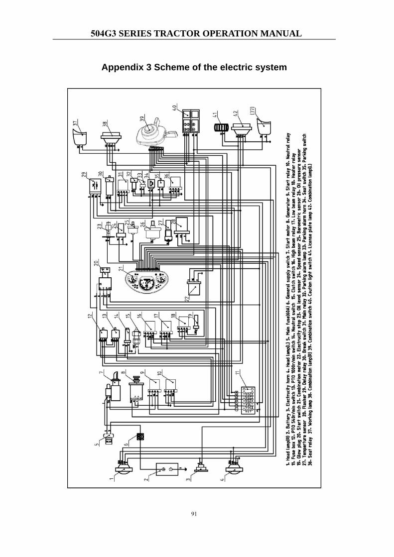
504G3 SERIES TRACTOR OPERATION MANUAL
91
Appendix 3 Scheme of the electric system
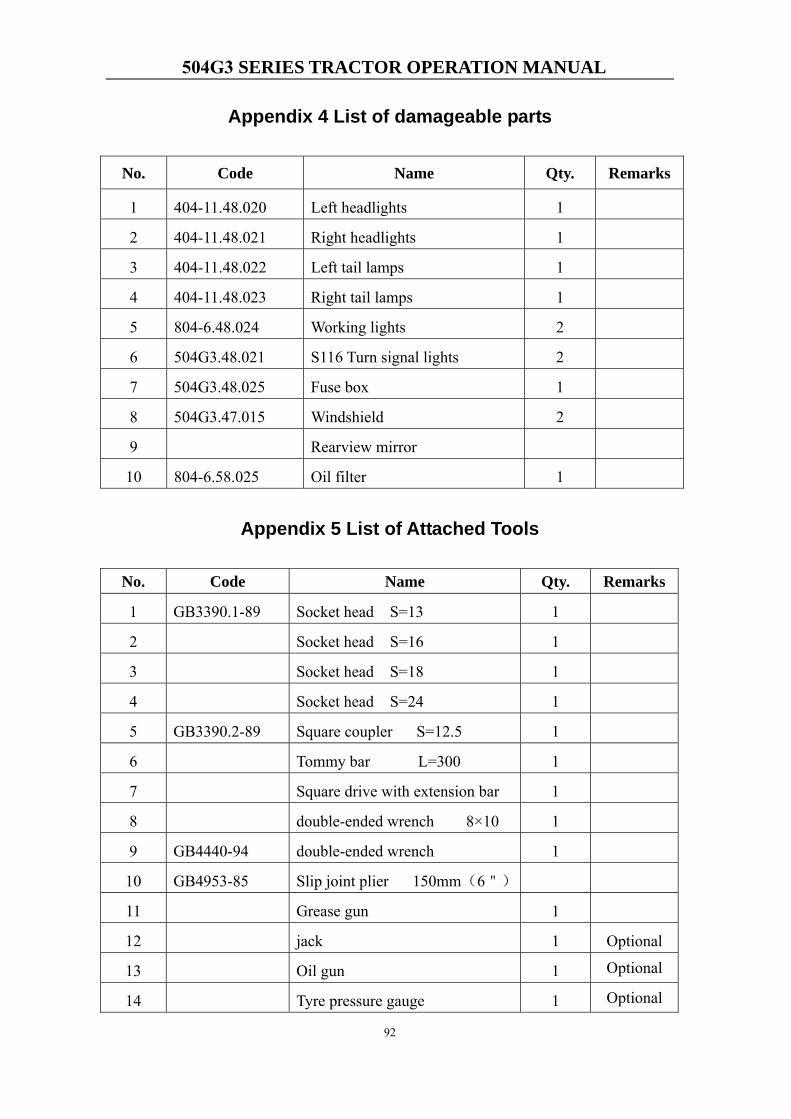
504G3 SERIES TRACTOR OPERATION MANUAL
92
Appendix 4 List of damageable parts
No. Code Name Qty. Remarks
1 404-11.48.020 Left headlights 1
2 404-11.48.021 Right headlights 1
3 404-11.48.022 Left tail lamps 1
4 404-11.48.023 Right tail lamps 1
5 804-6.48.024 Working lights 2
6 504G3.48.021 S116 Turn signal lights 2
7 504G3.48.025 Fuse box 1
8 504G3.47.015 Windshield 2
9 Rearview mirror
10 804-6.58.025 Oil filter 1
Appendix 5 List of Attached Tools
No. Code Name Qty. Remarks
1 GB3390.1-89 Socket head S=13 1
2 Socket head S=16 1
3 Socket head S=18 1
4 Socket head S=24 1
5 GB3390.2-89 Square coupler S=12.5 1
6 Tommy bar L=300 1
7 Square drive with extension bar 1
8 double-ended wrench 8×10 1
9 GB4440-94 double-ended wrench 1
10 GB4953-85 Slip joint plier 150mm(6")
11 Grease gun 1
12 jack 1 Optional
13 Oil gun 1 Optional
14 Tyre pressure gauge 1 Optional
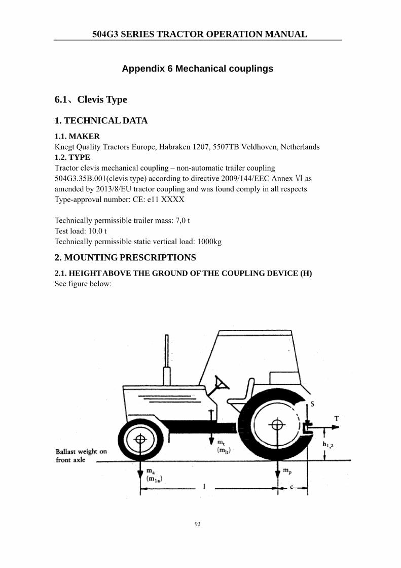
504G3 SERIES TRACTOR OPERATION MANUAL
93
Appendix 6 Mechanical couplings
6.1、Clevis Type
1. TECHNICAL DATA1.1. MAKER Knegt Quality Tractors Europe, Habraken 1207, 5507TB Veldhoven, Netherlands 1.2. TYPE Tractor clevis mechanical coupling – non-automatic trailer coupling 504G3.35B.001(clevis type) according to directive 2009/144/EEC Annex Ⅵ as amended by 2013/8/EU tractor coupling and was found comply in all respects Type-approval number: CE: e11 XXXX
Technically permissible trailer mass: 7,0 t Test load: 10.0 t Technically permissible static vertical load: 1000kg
2. MOUNTING PRESCRIPTIONS2.1. HEIGHT ABOVE THE GROUND OF THE COUPLING DEVICE (H) See figure below:
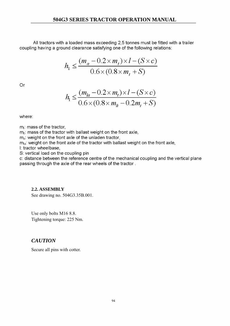
504G3 SERIES TRACTOR OPERATION MANUAL
94
2.2. ASSEMBLY See drawing no. 504G3.35B.001.
Use only bolts M16 8.8. Tightening torque: 225 Nm.
CAUTION Secure all pins with cotter.
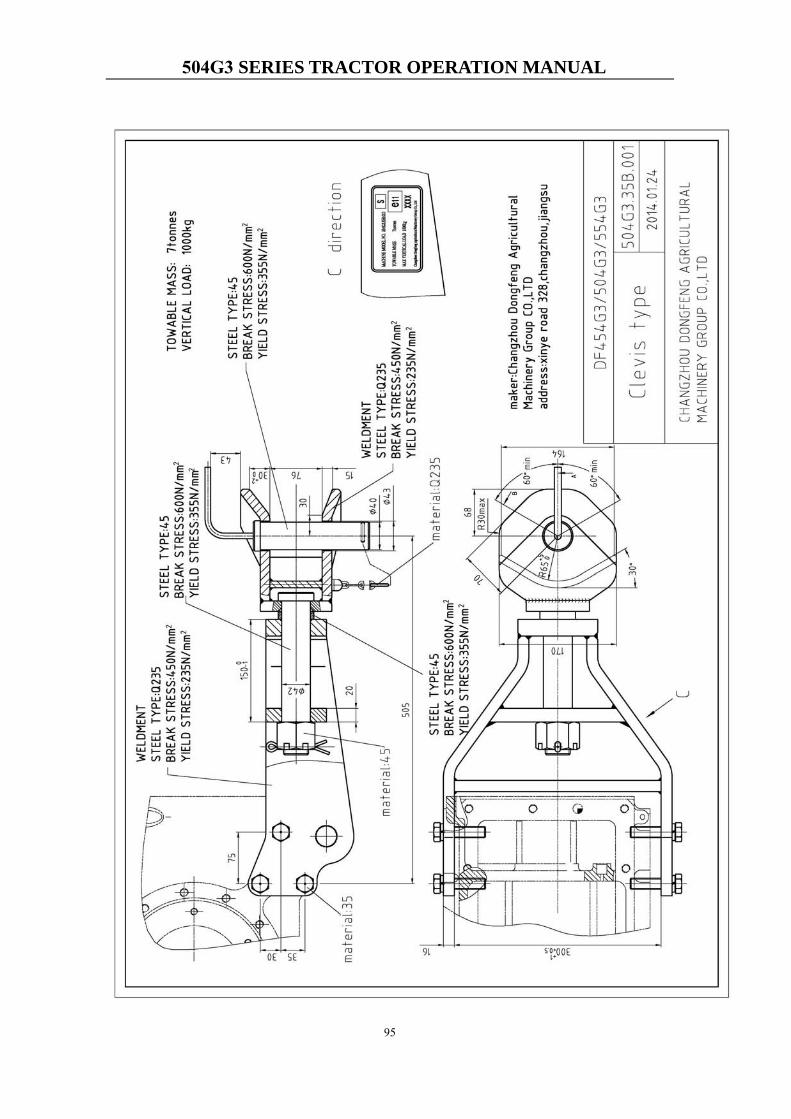
504G3 SERIES TRACTOR OPERATION MANUAL
95
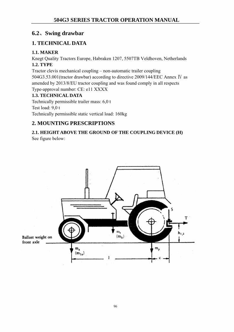
504G3 SERIES TRACTOR OPERATION MANUAL
96
6.2、Swing drawbar
1. TECHNICAL DATA1.1. MAKER Knegt Quality Tractors Europe, Habraken 1207, 5507TB Veldhoven, Netherlands1.2. TYPE Tractor clevis mechanical coupling – non-automatic trailer coupling 504G3.53.001(tractor drawbar) according to directive 2009/144/EEC Annex Ⅳ as amended by 2013/8/EU tractor coupling and was found comply in all respects Type-approval number: CE: e11 XXXX 1.3. TECHNICAL DATA Technically permissible trailer mass: 6,0 t Test load: 9,0 t Technically permissible static vertical load: 160kg
2. MOUNTING PRESCRIPTIONS2.1. HEIGHT ABOVE THE GROUND OF THE COUPLING DEVICE (H) See figure below:
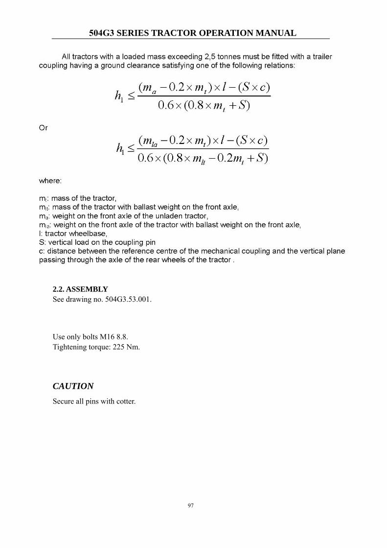
504G3 SERIES TRACTOR OPERATION MANUAL
97
2.2. ASSEMBLY See drawing no. 504G3.53.001.
Use only bolts M16 8.8. Tightening torque: 225 Nm.
CAUTION Secure all pins with cotter.
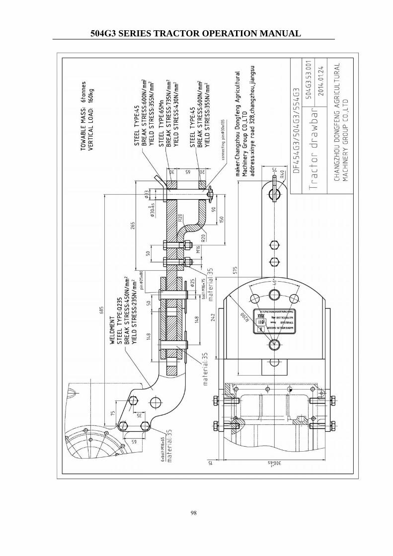
504G3 SERIES TRACTOR OPERATION MANUAL
98

99


504G3 SERIES TRACTOR OPERATION MANUAL
A
Index 1000h maintenance ...................................... 67 100h maintenance ........................................ 66 10h maintenance .......................................... 65 250h maintenance ........................................ 66 500h maintenance ........................................ 66 50h maintenance .......................................... 66 Adjust Seat and Steering Wheel .................. 41 Adjustment of parking braking system ........ 73 Adjustment of rockshaft system .................. 80 Adjustment of service braking system......... 73 Adjustment of the Brake .............................. 72 Adjustment of the Chassis ........................... 73 Adjustment of the clutch ............................. 71 Adjustment of the engine............................. 71 Adjustment of the Front Axle (4WD) .......... 75 Adjustment of the toe-in .............................. 79 Adjustment of the wheel track ..................... 79 Application Packing List ........................... 108 Ballast .......................................................... 59 Battery ......................................................... 61 Before Starting the Engine .......................... 43 Braking system ............................................ 84 Capacities .................................................... 24 Charging Systm Indicator ............................ 45 Check Instruments after Starting ................. 45 Clutch .......................................................... 82 Combination Switch .................................... 36 Component Identification Plates ................. 18 Coolant Temperature Gauge ........................ 45 Draw the Tractor .......................................... 50 Driving the Tractor ...................................... 46 Electrical system .......................................... 88 Electricity and instrument panel .................. 23 E-MARK certificate .................................. 101 Engine .......................................................... 21 Engine Identification Plate Location ........... 18 Equipment ................................................... 23 Farm implements to be attached .................. 24 Front driven axle (4WD) ............................. 84 Gearbox ....................................................... 83 Generator and voltage regulator .................. 60 Getting on and leaving the tractor ............... 40 Heating system ............................................ 89
Hoist tractor ................................................. 51 Hydraulic Hitch System .............................. 87 Hydraulic lift system control lever .............. 52 Hydraulic steering system ........................... 85 Identifying your machine ............................ 17 Ignition Switch ............................................ 33 Instrument and Controls .............................. 32 Instrument Panel .......................................... 34 Instrument Panel and Switch ....................... 33 Insurance device .......................................... 62 Jack tractor .................................................. 51 List of Attached Tools ................................. 93 List of damageable parts ............................. 93 Machine Identification Plate ....................... 17 Maintenance after running-in ...................... 30 Measures for emergency ............................. 16 Mechanical couplings .................................. 95 Noise ........................................................... 25 Oil and lubricants ........................................ 64 Oil Pressure Indicator .................................. 45 Operating the Engine ................................... 43 Operating the tractor safely ........................... 6 Optional Accessories ................................. 108 Periodic Service .......................................... 65 Preparation after Storage ............................. 70 Preparation before Running-in of the tractor ..................................................................... 27 Preparation for Storage ................................ 69 PTO ....................................................... 58, 86 Rear axle...................................................... 83 ROPS Certification Plate ............................. 18 Running in of hydraulic hitch system .......... 28 Running in of PTO ...................................... 29 Running in of the Tractor ............................ 29 Running-in of hydraulic steering system ..... 28 Running-in the engine without load ............ 27 Safety first ..................................................... 5 Safety Instructions ......................................... 5 Safety symbols ............................................ 12 Scheme of the electric system ..................... 92 Seat Belt ...................................................... 42 Service Daily Before Start-Up .................... 43
504G3 SERIES TRACTOR OPERATION MANUAL
B
Standards and Regulations .......................... 90 Start in Cold Weather .................................. 44 Start motor ................................................... 61 Start the Engine ........................................... 43 Start the tractor ........................................ 6, 46 Steering Wheel ............................................ 42 Stopping Tractor .......................................... 49 Switch plate ................................................. 37 Technical specification of the tractor ........... 19 The use of electrical systems ....................... 60 Tightening Torque Table of Main Bolts and Nuts ............................................................. 91 Towing loads ................................................. 8 Tractor characteristic ................................... 17 Tractor Controls ........................................... 32 Tractor Drawbar Or Clevis type Certification Plate ............................................................. 18 Tractor Maintenance ...................................... 9 Tractor maintenance during storage ............ 70
Tractor specification .................................... 19 Transmission ............................................... 21 Travelling and steering system .................... 22 Use 3-Point Hitch ........................................ 56 Use Draw Bar .............................................. 58 Use hydraulic output system ....................... 55 Use of the 4WD ........................................... 48 Use of the Brakes ........................................ 47 Use of the Differential Lock ........................ 47 Use of the hydraulic steering system ........... 49 Use of the tires ............................................ 49 Use operator’s set ..................................... 41 Using Agricultural Implements and Machines ....................................................................... 8 Using the Tractor implents .......................... 52 Vibration ...................................................... 25 Walking system ........................................... 85 Warm Up the Engine ................................... 45 Watch Fuel Level ........................................ 45

NO.DF504G3-E-2018EC
Version: NO.00.00.00
First Print: September 2018
Knegt Quality Tractors EuropeAdd: Habraken 1207, 5507TB Veldhoven, NetherlandsTel:+31-40 2558416E-mail: [email protected]://www.knegt-international.com