operation manual - · pdf filecapable of measuring leeb hardness of all metallic materials....
TRANSCRIPT

ModelNo.PHT‐1800/PHT‐1840&PHT‐1850
OperationManual
21IndustrialAvenueUpperSaddleRiverNJ07458
(201)962‐7373www.phase2plus.com

1
1Overview 3
1.1Advantages 31.2MainApplication&TestingRange.....................................................................31.2.1MainApplication...................................................................................................31.2.2TestingRange.........................................................................................................31.3TechnicalSpecifications........................................................................................31.4Configuration.............................................................................................................41.5WorkingConditions................................................................................................5
2StructureFeature&TestingPrinciple 52.1StructureFeature......................................................................................................62.1.1DTypeImpactDevice.........................................................................................62.1.2DifferentTypesofImpactDevice..................................................................72.2MainScreen................................................................................................................72.3KeypadDefinitions..................................................................................................82.4LeebHardnessTestingPrinciple........................................................................9
3Preparation 103.1InstrumentPreparationandInspection......................................................103.2ImpactDeviceSelection......................................................................................103.3PreparationoftheSampleSurface.................................................................11
4TestingProgram 124.1Start‐Up......................................................................................................................124.2Loading......................................................................................................................124.3Localization..............................................................................................................124.4Testing........................................................................................................................124.5ReadMeasuredValue..........................................................................................134.6Notification..............................................................................................................13
5OperationDetail135.1PowerOn/Off..........................................................................................................135.2MaterialSetting......................................................................................................145.3Hardness/Strengthtesting.................................................................................155.4ImpactDirectionSetting.....................................................................................155.5AverageTimesSetting.........................................................................................155.6Datalogging..............................................................................................................155.6.1Viewingstoredfile/Group.............................................................................155.6.2Clearingselectedfile/Group..........................................................................165.7PrintReport.............................................................................................................165.8SystemReset...........................................................................................................165.9ELBacklight.............................................................................................................175.10AutoPowerOff....................................................................................................175.11BatteryReplacement.........................................................................................175.12ConnectingtoaComputer..............................................................................17
5.13ErrorCodeReference....................................................................................................17
26
Effective:December6,2011
WarrantyPolicy:
Allportableandstationarymaterialtestinginstrumentsmanufacturedfor/byPhaseIIshallbefreefromdefectsinmaterialandworkmanshipforaperiodof1to5fullyears(dependinguponmodel)fromdateofpurchase.PartsfoundtobedefectiveshallbereplacedorrepairedatPhaseII’ssolediscretion.ProductsfoundbyPhaseIItobemisused,abusedorneglectedarenotcoveredunderthiswarranty.Partsnotcoveredbythiswarrantyarenormalwearandconsumableitemssuchas(butnotlimitedto)impactballs,impactbodies,diamondindentors,carbideballindentors,impactsprings,cablesandconnectors,batteries,diamondstylus,contactprobes,etc.
Consumable(wearable)itemssuchascablesandprobeshavea90daywarrantyfromdateofpurchase.
Thiswarrantyisexclusiveandinlieuofallotherwarrantieswhetherwritten,oralorimplied,includinganyimpliedwarrantiesormerchantabilityorfitnessforaparticularpurpose.InnoeventshallPhaseIIbeliableforanyincidental,specialorconsequentialdamagesofanynature.
ReturnPolicy:
AllPhaseIIproductsmusthaveauthorizationpriortoreturn.
Ifproductisnotacceptableforanyreasonincludingapplicationissuesanddemonstrations,authorizationforreturnmustbeobtainedwithin10daysofreceiptofproduct.Unitmustbeinsamenewconditionitwasreceived.Failuretodosowillresultinanautomatic15%restockingfee.
Returnsafter30dayswillnotbeaccepted.

25
MainHeadquarters:U.S.APhaseIIMachine&Tool,Inc.21IndustrialAveUpperSaddleRiver,NJ.07458USATel:(201)962‐7373Fax:(201)962‐8353GeneralE‐Mail:[email protected] BEIJING,CHINAPhaseIIMeasuringInstruments(Beijing)Ltd.Room301,Bldg2QingYuanXiLi,HaidianDistrict,Beijing100192,ChinaTel:+86‐10‐59792409Fax:+86‐10‐59814851GeneralE‐mail:info@phase2china.com.cnMEXICOPhaseIIdeMexicoCalleANo.4PromerPisoCol.SanMarcosAzcapotzalcoC.P02020MexicoTel:011‐525‐5538‐39771Fax:sameGeneralE‐mail:phase2mexico@hotmail.comVENEZUELAPhaseIIHerramientasUniversalesEDCM.CA.Av.FranciscoLazoMartiCCPlazaSantaMonicaPBLocalSantaMonica,Caracas1040VenezuelaTel:212‐690‐28‐21Fax:212‐693‐29‐16E‐mail:[email protected]
2
6Maintenance&Servicing176.1ImpactDeviceMaintenance..............................................................................176.2InstrumentMaintenanceProgram.................................................................186.3FaultAnalysis&Evaluation...............................................................................186.4NoticeofTransportandStorageConditions
APPENDIX.................................................................................................................................18Table1.............................................................................................................................18Table2.............................................................................................................................20Table3.............................................................................................................................21
Table4…………………………………………………………………………………………24

3
1Overview1.1Advantages Widemeasuringrange.BasedontheprincipleofLeebhardnesstestingtheory.
CapableofmeasuringLeebhardnessofallmetallicmaterials. Large screen LCD, showing all functions and parameters. With background
light. Seven impact devices are available for special application. Automatic
identificationofimpactdeviceuponplugin. Testatanyangle,evenupsidedown. DirectdisplayofhardnessscalesHRB,HRC,HV,HB,HS,HL Large memory could store 100 groups (Relative to average times 1‐32 ) of
information including single measured value, mean value, impact direction,impacttimes,materialandhardnessscaleetc.
Batterysymbolshowingthecapacityofthebattery. Usercalibrationfunction. OutputviaUSBport.Microprintersupport. Compactplasticcase,suitableforuseunderpoorworkingconditions Continuous working period of no less than 100 hours with two alkaline
batteries(AAsize)Autopoweroff. Outsidedimensions:150×74×32mm Weight:245g
1.2MainApplication&TestingRange1.2.1MainApplication Diecavityofmolds Bearingsandotherparts Failureanalysisofpressurevessel,steamgeneratorandotherlargeequipment Large,hardworkpiece Testingofinstalledmachineryandpermanentlyassembledparts. Materialidentificationbaseduponhardnessrange Rapid testing in large range and multi‐measuring areas for large‐scale work
piece
1.2.2TestingRangeTestingrangerefertoTable1andTable2intheAppendix.
1.3TechnicalSpecifications ErrorandrepeatabilityofdisplayedvalueseeTable1‐1below.
24
Windows8InstallationPatch:ForallPHT‐seriesportablehardnesstesters1,ConnectthetestertoPCviaUSBcable.Poweruptheinstrument.2,Runzadig_2.1.2.exe
2,ActivateOptions/ListAllDevices.Thenselectthe“LeebHardnessTester”item.Selectthe“libusb‐win32(v1.2.6.0)”option.
3,PressdowntheInstallDriver/ReinstallDriverbutton.Waitforthedriverinstallingprocesscomplete.4,NowtheusbdriverfortheLeebHardnessTesterhasbeensuccessfullyinstalled.Youcannowrunthedataprosoftwaretocommunicatewiththehardnesstester.Note:Keeptheinstrumentpoweredupduringdriverinstallationandconnection.
TechSupport:(201)962‐8352

23
PHT‐1800DataOutputSoftwareInstallation:InsertCDintodriveonyourcomputerWindowwillpopupRunAutoRun.exeFollowpromptstoloadprogram,makesureyourdesignationdriveissettoC:Oncecompleteda“DataproforHardnessiconwillappearondesktopLaunchtheprogramusingtheDataproforHardnessiconondesktopshortcutUsingtheUSBcableprovidedinsertroundendtothehardnesstesterandUSBsidetoyourcomputerOnthesoftwarescreenselect“Connect”.ItwillaskforwhichCOMportyouareattachedto.SelectCOMport.Onceconnectedyoucanviewallsavedmemoryfilesonscreen.Therearealsoselectionsfor“Database”and“Reports”.
4
Table1‐1
No.Typeofimpactdevice
HardnessvalueofLeebstandardhardness
block
Errorofdisplayedvalue
Repeatability
1 D 760±30HLD530±40HLD
±6HLD±10HLD
6HLD10HLD
2 DC 760±30HLDC530±40HLDC
±6HLDC±10HLDC
6HLD10HLD
3 DL 878±30HLDL736±40HLDL ±12HLDL 12HLDL
4 D+15 766±30HLD+15544±40HLD+15 ±12HLD+15 12HLD+15
5 G 590±40HLG500±40HLG ±12HLG 12HLG
6 E 725±30HLE508±40HLE ±12HLE 12HLE
7 C 822±30HLC590±40HLC ±12HLC 12HLC
Measuringrange:HLD(170~960)HLD Measuringdirection:0~360° HardnessScale:HL、HB、HRB、HRC,HV、HS Display:4‐DigitLCD Datamemory:max.100groups(relativetoimpacttimes1‐32) Workingpower:3V(2AAsizealkalinebatteries) Continuousworkingperiod:about100hours(Withbacklightoff) Communicationinterface:USB
5
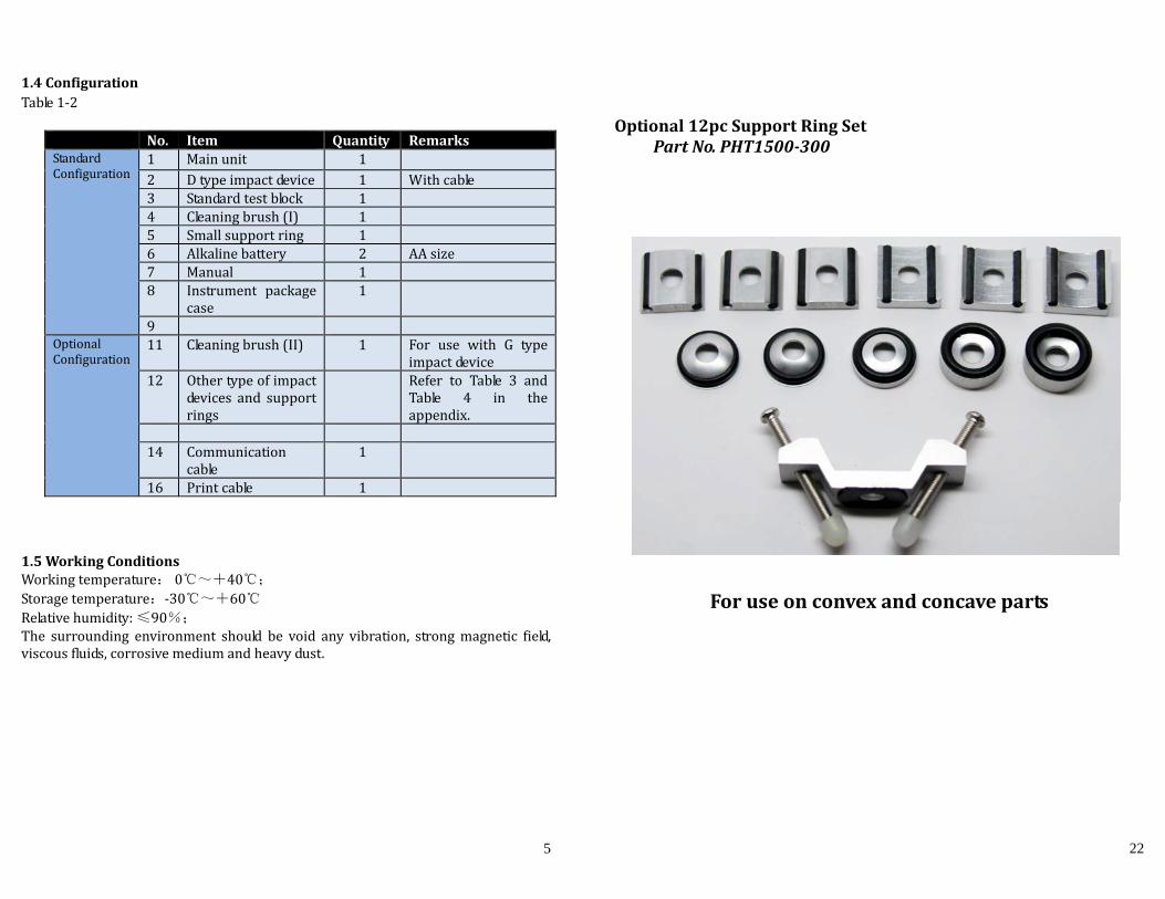
1.4ConfigurationTable1‐2
1.5WorkingConditionsWorkingtemperature:0℃~+40℃;Storagetemperature:‐30℃~+60℃Relativehumidity:≤90%;The surrounding environment should be void any vibration, strongmagnetic field,viscousfluids,corrosivemediumandheavydust.
No. Item Quantity RemarksStandardConfiguration
1 Mainunit 1 2 Dtypeimpactdevice 1 Withcable3 Standardtestblock 1 4 Cleaningbrush(I) 1 5 Smallsupportring 1 6 Alkalinebattery 2 AAsize7 Manual 1 8 Instrument package
case1
9 OptionalConfiguration
11 Cleaningbrush(II) 1 For use with G typeimpactdevice
12 Othertypeofimpactdevices and supportrings
Refer to Table 3 andTable 4 in theappendix.
14 Communication
cable1
16 Printcable 1
22
Optional12pcSupportRingSetPartNo.PHT1500‐300
Foruseonconvexandconcaveparts

21
Table3Typeofimpact
deviceDC(D)/DL D+15 C G E
ImpactingenergyMassofimpactbody
11mJ5.5g/7.2g
11mJ7.8g
2.7mJ3.0g
90mJ20.0g
11mJ5.5g
Testtiphardness:Dia.Testtip:
Materialoftesttip:
1600HV3mm
Tungstencarbide
1600HV3mm
Tungstencarbide
1600HV3mm
Tungstencarbide
1600HV5mm
Tungstencarbide
5000HV3mm
syntheticdiamond
Impactdevicediameter:
Impactdevicelength:Impactdeviceweight:
20mm86(147)/75mm50g
20mm162mm80g
20mm141mm75g
30mm254mm250g
20mm155mm80g
Max.hardnessofsample
940HV 940HV 1000HV 650HB 1200HV
MeanroughnessvalueofsamplesurfaceRa:
1.6μm 1.6μm 0.4μm 6.3μm 1.6μm
Min.weightofsample:
MeasuredirectlyNeedsupportfirmlyNeedcouplingtightly
>5kg2~5kg
0.05~2kg
>5kg2~5kg
0.05~2kg
>1.5kg
0.5~1.5kg0.02~0.5kg
>15kg5~15kg0.5~5kg
>5kg2~5kg
0.05~2kg
Min.thicknessofsampleCoupling
tightlyMin.layerthicknessforsurfacehardening
5mm≥0.8mm
5mm≥0.8mm
1mm≥0.2mm
10mm≥1.2mm
5mm≥0.8mm
SizeoftipindentationHardness300HV
IndentationdiameterDepthofindentation
0.54mm24μm
0.54mm24μm
0.38mm12μm
1.03mm53μm
0.54mm24μm
Hardness600HV
IndentationdiameterDepthofindentation
0.54mm17μm
0.54mm17μm
0.32mm8μm
0.90mm41μm
0.54mm17μm
Hardness800HV
IndentationdiameterDepthofindentation
0.35mm10μm
0.35mm10μm
0.35mm7μm
‐‐‐‐
0.35mm10μm
Availabletypeofimpactdevice
DC:Testholeorhollowcylindrical;DL:Testnarrowgrooveorhole
D+15:Testgrooves
C:Testsmall,light,thinpartsandsurfaceofhardenedlayer
G:Testlarge,,heavyandroughsurfacesteel
E: Testsuperhighhardnessmaterial
6
2StructureFeature&TestingPrinciple2.1StructureFeature
1. Mainunit2.Keypad3.LCDdisplay4SocketofUSB
5. Socketofimpactdevice6.Impactdevice7Label8.Batterycover
2.1.1DTypeImpactDevice
1234567
1Releasebutton 2Loadingtube 3Guidetube 4Coilunit
5Connectioncable 6Impactbody 7Supportring
POWER: 2 X 1.5V
HARDNESS GAUGE
0-Steel and Cast Steel1-Cold Work Tool Steel2-Stainless Steel3-Gray Cast Iron
4-Nodular Cast Iron5-Cast Aluminum Alloys6-Copper-Zinc Alloys7-Copper-Aluminum8-Wrought Copper9-Wrought Steel
Material Option:
4
1
2
3
5
6
7
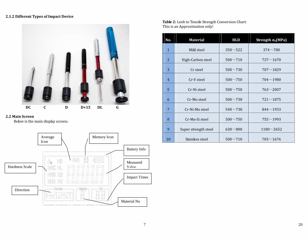
2.1.2DifferentTypesofImpactDevice
DCC DD+15DLG
2.2MainScreen
Belowisthemaindisplayscreen:
Hardness Scale
Average Icon
Direction
Battery Info
Impact Times
Measured Value
Material No
Memory Icon
20
Table2:LeebtoTensileStrengthConversionChart:ThisisanApproximationonly!
No. Material HLD Strengthσb(MPa)
1 Mildsteel 350~522 374~780
2 High‐Carbonsteel 500~710 737~1670
3 Crsteel 500~730 707~1829
4 Cr‐Vsteel 500~750 704~1980
5 Cr‐Nisteel 500~750 763~2007
6 Cr‐Mosteel 500~738 721~1875
7 Cr‐Ni‐Mosteel 540~738 844~1933
8 Cr‐Mn‐Sisteel 500~750 755~1993
9 Superstrengthsteel 630~800 1180~2652
10 Stainlesssteel 500~710 703~1676

19
HB
85~655
HV85~80
2
Greycastiron
HRC
HB93~33
4
92~326
HV
Nodularcastiron
HRC
HB131~387
127~364
HV
Castaluminumalloys
HB19~16
4
23~210
32~168
HRB23.8~84.6
22.7~85.0
23.8~85.5
BRASS(copper‐zincalloys)
HB40~17
3
HRB13.5~95.3
BRONZE(copper‐aluminum/tinalloys)
HB60~29
0
Wroughtcopperalloys
HB45~31
5
8
InstructionoftheMainDisplayScreen:Material:Thepresentpresettingmaterial.
Impactdirection:Thepresentimpactdirection.
Hardnessscale:Hardnessscaleofthepresentmeasuredvalue.
Batteryinformation:Showsremainingbatterycapacity
Measured value:Display present single time measured value(without showingaverageicon),ordisplaythepresentmeanvalue(withaverageiconprompting).“‐HI‐” means over conversion value or measure range. “‐LO‐” means lower thanconversionvalueormeasurerange.
Impacttimes:Timesthathavebeentested
Average Icon:Itwillappearwhenshowingthemeanvalueofthemeasuredvaluesafterreachingthepresettingimpacttimes.
MemoryIcon:Itappearswhenoperatingtheinstrumentmemory.
2.3KeypadDefinitionsTable2‐1
Turnon/offthe ELbacklight
Data Save or DataDelete
Turn theinstrumenton/off
MaterialSelection
Hardness/Strengthswitch
PlusorUp
Hardness ScaleSelection
Directionchange Minus orDown
Printdata
ImpactTimesset Datalogging orEnter

9
Press key to store present group of measured value into memory. This
operationisonlyvalidafterdisplayingthemeanvalue.
Presskey and coulddisplaysinglemeasuredvalue.
Press keycouldswitchonoroffthebackgroundlightofLCD.
Press keytosettheimpactdirection.
Press key tochange the impact times inonegroup.The impact times item
will flashwhenfirstpressingthe key,andthentheimpacttimesvaluewill
plus orminuswhen pressing the or key. Press key finally to exit
fromchangingtheimpacttimesprocess.
Press keytochangethehardnessscale.
Press keytochangethematerial.PresettinghardnessscalerecoverstoHL
automaticallyaftermaterialpresettingchanged.
Press keytoswitchbetweenhardnesstestandstrengthtest.OnlyDandDC
typeofimpactdevicehasthefunctionofstrengthtesting.Sohardnesstestingis
theonlyselectioniftheimpactdeviceisnotDorDCtype.
Press keytoprintoutthemeasuredvaluesaftermeasurement.
2.4LeebHardnessTestingPrincipleIt is defined as the quotient of an impact body’s rebound velocity over its impactvelocity, multiplied by 1000. Harder materials produce a higher rebound velocitythan softermaterials. For a specific group ofmaterial (e.g. steel, aluminum. etc.).Leebhardnessvaluerepresentsadirectrelationshiptoitshardnessproperties. Forordinary metal, conversion curves of hardness HL versus other standard statichardness (HB, HV, HRC, etc.) are available, enabling you to convert HL into otherhardnessvalues.
18
Releasetheimpactbodyafteruse. NEVERUSELUBRICANTORCLEANERSONIMPACTDEVICE!
6.2InstrumentMaintenanceProgram WhentestingintheRockwellChardnessscaleyourerroramountshouldnot
exceed2RockwellCpoints.Changingthesphericaltesttiporimpactbodyshouldbeconsidered.
WarrantywillbeVOID ifunithasbeendismantledbysomeoneotherthananauthorizedrepairperson
6.3FaultAnalysis&EvaluationFaultAppearance FaultAnalysis RepairmethodFailuretopoweron LowordeadBattery ReplacethebatteriesNomeasuredvalue Impactdevicecablefailure Replacethecable
APPENDIXTable1
Material MethodImpactdevice
D/DC D+15 C G E DL
Steelandcaststeel
HRC20~68.
519.3~67.9
20.0~69.5
22.4~70.
720.6~68.2
HRB38.4~99.6
47.7~99.9
37.0~99.9
HB127~651
80~638
80~683
90~646
83~66381~64
6
HV83~97
680~93
780~99
6 84~1042
80~950
HS32.2~99.5
33.3~99.3
31.8~102.1
35.8~10
2.630.6~96.8
Coldworktoolsteel
HRC20.4~67.1
19.8~68.2
20.7~68.2
22.6~70.
2
HV80~89
880~93
5100~941
82~1009
Stainlesssteel
HRB46.5~101.7

17
5.9ELBacklight WiththeELbackgroundlight,itisconvenienttoworkindarkerconditions.Presskey toswitchonorswitchoffthebackgroundlightatanymomentasyouneed after power on. Since theEL lightwill consumemorepower, turnon it onlywhennecessary.5.10AutoPowerOff
The instrument features an auto power off function designed to conservebattery life. If the tool is idle (neither measuring nor any key operation) for 5minutes,itwillturnitselfoff.Beforepoweringoff,theLCDdisplayoftheinstrumentwillcontinueflashingfor20seconds.TopreventtheunitfrompoweringoffyoucanpressanybuttonExcept Power.
Whenthevoltageofthebatterygetstoolow,thedisplaywillshow<E00>,thenpoweroffautomatically.5.11BatteryReplacement
The PHT‐1800 uses standard AA batteries. After several hours of usage, thebattery symbol on the screen will begin to show less dark tabs which is shownas . When the batteries are drained, the battery symbol will be shown as
andwillbegintoflash.Whenthisoccurs,thebatteriesshouldbereplaced.Payattentiontothepolarityofthebatteries!Pleaseproperlydisposeofusedbatteriesaccordingly.5.12ConnectingtoaComputer
TheInstrumentisequippedwithaUSBserialport.Usingtheoutputcablethegauge has the ability to connect to a computer, or external storage device.Measurement data stored in the memory of the gauge can be transferred to thecomputerthroughtheUSBport.5.13ErrorCodeReference
ErrorCode Explanation ErrorCode ExplanationE00 ReplaceBattery E05 Can’tprintE01 Valueoutofrange E06 E02 Measurement
notfinishedE07
E03 Dataalreadysaved E08 E04 Nomemorydata E09
6Maintenance&Servicing6.1ImpactDeviceMaintenance
Aftertheimpactdevicehasbeenusedfor1000‐‐2000times,pleaseusethenylon brush provided to clean the guide tube and impact body. Whencleaning the guide tube, unscrew the support ring first, then take out theimpactbody,spiral thenylonbrush incounter‐clockwisedirection intothebottomof guide tube and repeat a few times to removeanydust or smallchipsinsidethetube.Theninstalltheimpactbodyandsupportringagain.
10
3Preparation3.1InstrumentPreparationandInspectionCalibrationoftheinstrumentisperformedbyusingastandardcalibratedtestblock.The error and repeatability of displayed value should be within +/‐6HL points (Ddevice) The instrument and impact device must be calibrated using a standardhardnessblockpriortofirstusageorhavingresettheinstrumentsystem.Press key,whilesimultaneouslypressingdownthe keytopoweronthesystem.Thecalibrationscreenshowsasbelow.
Take 5 tests on your standard
hardness block. The display will
showtheaveragemeasuredvalue
after measuring 5 times. Press
key to change to its
nominal value tomatch thevalue
shownonyourtestblock.
Press key to confirm the
calibration.Orpressthe keyto
cancelthecalibration.
Rangeofadjustment:±30HL.
Themeasurementparameters,includingthematerialsetting,thehardnessscaleandtheimpactdirectioncan’tbechangedduringcalibration.
3.2ImpactDeviceSelection RefertoAppendixTable1andTable3forselectionofimpactdevice.
Note:For Verification, Take 5 tests around the test block and get your average. This average value should be within the acceptable tolerance of the test block value. If this value exceeds the allowable tolerance of the test block, a calibration should be performed. See above.

11
3.3PreparationoftheSampleSurfacePreparation for sample surface should conform to the relative requirement inAppendixTable3.
Test surfaces should be at or close to room temperature for optimalperformance
To eliminate hardness errors resulting from the roughness of a sample’ssurfacewhenusingimpactdeviceD,DCorD+15,thetestsurfaceshouldbepolisheduntil itsroughnessRa isnomorethan2m.PHASEIISRG‐2000handheldsurfaceroughnesstesteroranyothersuitableinstrumentmaybeused to measure the surface roughness of the samplematerial. The testsurfaceshouldbecleanandfreefromoilstains.
Supportoftestsample.Supportisnotnecessaryforheavysamples.Lighterweightpartsmustbesetontheflat,smoothsurfaceofalargermassmetalobject. The sample must be completely stationary and without any gapsbetweenthetwoparts.
Curved surface: The best testing surface of sample is flat. When thecurvatureradiusRofthesurfacetobetestedissmallerthan30mm(D,DC,D+15,C,EandDLtypeofimpactdevice)andsmallerthan50mm(Gtypeofimpactdevice), thesmall support ringor theshapedsupport ringsshouldbechosen.
Thesampleshouldhaveenoughmass.MinimumthicknessofsampleshouldconformtoTable3.
Forthesamplewithhardenedlayeronsurface,thedepthofhardenedlayershouldconformtoTable3.
Coupling. Light‐weight sample must be firmly coupled to a part with much
larger mass. Both coupled surface must be flat and smooth. The impactdirectionmustbeverticaltothecoupledsurface.Whenthesampleisabigplate,orlongrod,itcanbedeformedandbecomeunstable,eventhoughitsweightandthicknessiswithinallowableranges,andaccordingly,thetestvaluemaynotbeaccurate.Sothesampleshouldbereinforcedorsupportedatitsback.
16
4) Usethe keyandthe keytovieweachsinglemeasureddatainthatgroupwhileviewingdetails.
5) Pressthe keytoreturntopreviousscreenatanytimeduringdatalogging.5.6.2Deletingselectedfile/Group
Theusermayrequiredeletingafilefromtheinstrumentmemory.Theprocedureisoutlinedinthefollowingsteps.1) Press the key to activate the data logging function. Thememory iconwill
appear.Itwilldisplaythecurrentfilename,thetestparameterofthegroupdataand the mean value of the group. If there is no data in the memory, it willdisplay:<E04>,whichmeansnomemorydata,andthenreturnback.
2) Usethe keyandthe keytoscrolltothefilethatwillbedeleted.3) Press the key on the desired file. It will automatically delete the file, and
display“‐DEL”.4) Press the key, at any time, to exit the data logging function and return to
measurementmode.Note:Donotshutdowntheinstrumentwhiledeletingdata.Itcouldleadtolossofalldataifshutdownwhiledeleting.5.7PrintReport
Attheendoftheinspectionprocess,orendoftheday,theusermayrequirethereadingsbeprinted.
Before printing, please insert one connection plug of the print cable into thesocket on the upper left side of themain body, and insert the other plug into thecommunication socket of your PC. You can print out the measurement resultimmediatelyaftereachtestingprocess,byeasilypressingthe key.
Ifyouwanttoprintthedatastoredintheinstrumentmemory,thenfollowthesesteps:
1. Press the key to activate the data logging function. Thememory iconwillappear.
2. Usethe keyandthe keytoselectthedesiredfile.3. Pressthe keytoprinttheselectedfile.Thisoperationwillsendallthedatain
currentfiletotheminiprinterviaRS232portandprintthemout.4. Pressthe keytoexitthedataloggingfunctionsandreturntomeasurement
mode.5.8SystemReset Press down the key while powering on the instrument will restorefactorydefaults.Theonlytimethismightpossiblyhelpfulisifoneoftheparametersinthegaugeweresomehowcorrupted.

15
0 Mildsteel 5 Cr‐Mosteel1 Highcarbonsteel 6 Cr‐Ni‐Mosteel2 Crsteel 7 Cr‐Mn‐Sisteel3 Cr‐Vsteel 8 Superstrengthsteel4 Cr‐Nisteel 9 Stainlesssteel
5.3Hardness/Strengthtesting
Press keytoswitchbetweenhardnesstestingandstrengthtesting(бb).Note:OnlyDandDCtypeofimpactdevicehasthefunctionofstrengthtesting.SohardnesstestingistheonlyselectioniftheimpactdeviceisnotDorDCtype. In hardness testing, Press key to change the hardness scale. Thesupportedhardnessscaleincludes:HL,HV,HB,HRC,HSandHRB.Note:
This displays the valid hardness scale for the present selected impactdeviceandmaterial.Itwouldnotdisplaythehardnessscalewhichisnotvalid.
Pleaseselectmaterialfirst,thenselecthardnessscale. PresettinghardnessscalerecoverstoHLautomaticallyafterpresetting
materialischanged.5.4ImpactDirectionSettingPressthe keytomovetotheimpactdirectionthatyouwillworkin.5.5AverageTimesSetting
Youcouldmodifyaveragetimeswithintherangeof1to32asfollowing:1) Press keyintestingstate.Theimpacttimesitemwillbegintoflash;2) Press or keytosettheaveragetimestothenumberyouwant.3) Press keyfinallytoexitfromtheoperation.
5.6DataloggingAtmostonehundredfiles(F00‐F99,onegroupasonefile)canbestoredinside
the gauge. By simply pressing the key after a newmeasurement finishes‐thescreenshowingthe“AVE”icon,themeasuredhardness/strengthgroupvalueswillbesavedtomemory.Thenewsavedfileisappendedasthelastfileofthememory.Thisfunction provides the user with the ability to view/delete a file/group previouslysavedinmemory.5.6.1Viewingstoredfile/Group
Toviewthememorydata,followthesteps:1) Press the key to activate the data logging function. The memory icon will
appear.Itwilldisplaythecurrentfilename,thetestparameterofthegroupdataandthemeanvalueofthegroup.Ifthereisnodatainthememory,itwilldisplay:<E04>,whichmeansnomemorydata,andthenreturnback.
2) Usethe keyandthe keytoselectthedesiredfiletoview.3) Pressthe keytoseedetailsofthatgroupdata.
12
AVOIDanyobjectthathasastrongMagneticForce.4TestingProgram4.1Start‐Up
Inserttheplugoftheimpactdeviceintothesocketofimpactdeviceontheinstrument.
Pressthe keytopowertheuniton.Theinstrumentreadyfortesting.
4.2LoadingPushing the loading‐tubedownwardsuntil contact is felt. Then allow it to slowly
returntothestartingpositionorusingothermethodlockingtheimpactbody.
4.3PlacementPress the impactdevice supporting ring firmlyon thesurfaceof thesample, the
impactdirectionshouldbeverticaltothetestingsurface.
4.4Testing Pressthereleasebuttonontheupsideoftheimpactdevicetotest.Thesample,
theimpactdeviceaswellastheoperatorareallrequiredtobestable.Theactiondirectionshouldpasstheaxisoftheimpactdevice.
Eachmeasuredareaofthesampleusuallyneed3to5timesoftestingoperationto obtain an average. The result data dispersion should notmore thanmeanvalue±15HL。
ThedistancebetweenanytwoimpactpointsorfromthecenterofanyimpactpointtotheedgeoftestingsampleshouldconformtotheregulationofTable4‐1.
13
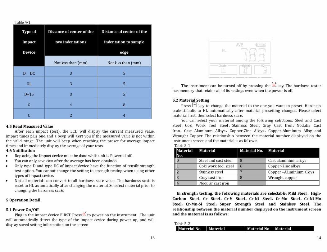
Table4‐1
Typeof
Impact
Device
Distanceofcenterofthe
twoindentations
Distanceofcenterofthe
indentationtosample
edge
Notlessthan(mm) Notlessthan(mm)
D、DC 3 5
DL 3 5
D+15 3 5
G 4 8
C 2 44.5ReadMeasuredValue
After each impact (test), the LCD will display the current measured value,impacttimesplusoneandabeepwillalertyouifthemeasuredvalueisnotwithinthe valid range. The unit will beep when reaching the preset for average impacttimesandimmediatelydisplaytheaverageofyourtests.4.6Notification ReplacingtheimpactdevicemustbedonewhileunitisPoweredoff. Youcanonlysavedataaftertheaveragehasbeenobtained. OnlytypeDandtypeDCof impactdevicehavethefunctionoftensilestrength
testoption.Youcannotchangethesettingtostrengthtestingwhenusingothertypesofimpactdevice.
Notallmaterialscanconvert toallhardnessscalevalue.Thehardnessscale isresettoHLautomaticallyafterchangingthematerial.Soselectmaterialpriortochangingthehardnessscale.
5OperationDetail5.1PowerOn/Off
PlugintheimpactdeviceFIRST.Press topowerontheinstrument.Theunitwill automatically detect the type of the impact device during power up, andwilldisplaysavedsettinginformationonthescreen
14
The instrumentcanbe turnedoffbypressing the key.Thehardness testerhasmemorythatretainsallofitssettingsevenwhenthepowerisoff.
5.2MaterialSetting
Press key tochange thematerial to theoneyouwant topreset.Hardnessscale defaults to HL automatically after material presetting changed. Please selectmaterialfirst,thenselecthardnessscale.
You can select your material among the following selections: Steel and CastSteel、Cold Work Tool Steel、Stainless Steel、Gray Cast Iron、Nodular CastIron、Cast Aluminum Alloys、Copper‐Zinc Alloys、Copper‐Aluminum Alloy andWrought Copper. The relationship between thematerial number displayed on theinstrumentscreenandthematerialisasfollows:Table5‐1MaterialNo.
Material MaterialNo. Material
0 Steelandcaststeel 5 Castaluminiumalloys1 Coldworktoolsteel 6 Copper‐Zincalloys2 Stainlesssteel 7 Copper–Aluminiumalloys3 Graycastiron 8 Wroughtcopper4 Nodularcastiron
Instrength testing, the followingmaterialsareselectable:MildSteel、High‐Carbon Steel、Cr Steel、Cr‐V Steel、Cr‐Ni Steel、Cr‐Mo Steel、Cr‐Ni‐MoSteel、Cr‐Mn‐Si Steel、Super Strength Steel and Stainless Steel. Therelationshipbetweenthematerialnumberdisplayedontheinstrumentscreenandthematerialisasfollows:Table5‐2
MaterialNo Material MaterialNo Material