operation manual - prestcon
TRANSCRIPT

OPERATION MANUAL FOUR SIDE PLANER
WINTER TIMBERMAX 4-18 S
WARNING!
The operator must thoroughly read this manual before operation. Keep this manual for future reference.
Henrik Winter Holztechnik GmbH
Druckereistr. 8 04159 Leipzig
Tel: +49 (0)341/ 4619021 Fax: +49 (0)341/4618358 Funk: +49 (0)171/2820443
Em@il: [email protected] Internet: www.winter-holztechnik.de

MACHINE : FOUR SIDED PLANNER
TYPE: VS-20N1
OPERATION MANUAL
Page 2
T O O U R C U S T O M E R S
This manual contains all the instructions required for the faultless operation of the ma-
chine and its respective maintenance, as well.
Thus, during the warranty period, you will receive for free all components that have
presented eventual defects.
The producer is always at your disposal for resolving of problems that machine opera-
tors may encounter during operation, and for delivery of spare parts, too.
Your recommendations related to this manual are valuable contribution to the improve-
ment of the products offered by ZMM “Stomana” JSC to its customers.

MACHINE : FOUR SIDED PLANNER
TYPE: VS-20N1
OPERATION MANUAL
Page 3
CONTENTS
SECTION A: GENERAL DATA
A.1. MANUFACTURER
A.2. INTRODUCTION
A.3. CORRESPONDENCE
A.4. NAME PLATE
A.5. FIELD OF APPLICATION
A.6. WORKING CONDITIONS AND REQUIREMENTS
A.7. TECHNICAL CHARACTERISTICS
A.8. NOISE CHARACTERISTICS
SECTION B: SAFETY OF WORK
B.1. SAFETY INSTRUCTIONS
B.2. DESIGN MEASURES FOR ENSURING SAFETY FOR WORK
SECTION C: ASSEMBLY OF MACHINE
C.1. REQUIREMENTS TO THE WORKING AREA
C.2. UNLOADING OF MACHINE
C.3. DESLUSHING OF MACHINE
C.4. FOUNDATIONS LAYOUT
C.5. ASSEMBLY OF THE DISASSEMBLED UNITS
C.6. CONNECTION TO THE MAINS
C.7. CONNECTION TO THE ASPIRATION DEVICE
SECTION D: FITTING AND OPERATING OF MACHINE
D.1. OPERATING OF MACHINE
D.2. STARTING THE MACHINE
D.3. STOPPING THE MACHINE
D.4. OPERATION
SECTION E: DESCRIPTION OF MACHINE
E.1. TECHNOLOGICAL PART
E.2. ELECTRICAL PART
SECTION F: MAINTENANCE
F.1. CLEANING OF MACHINE
F.2. LUBRICATION OF MACHINE
F.3. CHECKING THE CONDITION OF SOME UNITS AFTER OPERATION
F.4. TROUBLE-SHOOTING
SECTION G: APPENDICES
G.1. WIRING DIAGRAM AND LIST OF THE ELECTRICAL COMPONENTS
G.2. ELECTRIC CABINET – LAYOUT OF COMPONENTS
SECTION H: CATALOGUE OF SPARE PARTS

MACHINE : FOUR SIDED PLANNER
TYPE: VS-20N1
OPERATION MANUAL
Page 4
SECTION A: GENERAL DATA
A.1. MANUFACTURER
A.2. INTRODUCTION
The present manual is designed for those who will operate the machine. You will find in it the neces-
sary data for assembly, commissioning, maintenance and safety operation of the machine. The experience
of the company manufacturer and its experts in considered in the preparation of this manual.
We recommend you to consider with responsibility our recommendations concerning the safety of
work. The operations requiring disassembly of machine and electrical components should be performed
by authorized and qualified personnel only. Repairs and settings not described in the present manual
should not be performed. This manual is prepared by the manufacturer and is an integral part of the ma-
chine's delivery. The information contained herein is intended for specialists and is compulsory.
The manual defines the machine's field of application and contains all the information necessary for its
proper and safety operation.
The permanent and exact observation of the instructions contained in this manual ensure safety of per-
sonnel and machine, profitable work as well as long life of the machine itself.
For better clarity this manual is divided in separate parts in which are contained the more important
subjects.
The contents will allow you to find fast the specific subjects.
The important text is printed in bold and is marked by the following symbols:
WARNING
This means that you should proceed very carefully in order to avoid situations that could be dan-
gerous to human life or may cause serious injury to the personnel.
ATTENTION
Provides information about situations that may occur during the life of the product, the system or
the equipment and that may cause injury to the personnel, damages on the machine, environmental
pollution or financial loss.
CAUTION
Means that you should be more cautious in order to avoid material damage.
INFORMATION
Very important instructions.
Some figures and information in this manual may not coincide with those of the machine purchased by
you.
ZMM “STOMANA” JSC , SILISTRA, BULGARIA
Tel.: 086 /821058; Commercial Dpt. 086 /821052, 16 Tutrakan Blvd.
Fax : 086 /821071 E-mail: [email protected] , www.stomana.net
i
= > ? @ A B C A ? D > @ = E F G D > H I ? A B J K L =M @ N H B > @ > A O D @ P QR S T U V W > A X G A YM > N D O H I F Z ? [

MACHINE : FOUR SIDED PLANNER
TYPE: VS-20N1
OPERATION MANUAL
Page 5
The producer is constantly working on the improvement and renovation of the product and may intro-
duce modifications without prior notification.
At preparation of this manual are considered all the operations belonging to "normal servicing". Repair
works and other operations not mentioned in the manual should not be undertaken.
All operations requiring disassembly of machine parts should be carried out by technically qualified
personnel.
The instructions of this manual should be observed for correct usage of the machine.
Use only original spares of ZMM "Stomana" JSC.
The manufacturer should not be held responsible for damages caused by the use of spares which are
not original.
INFORMATION
The machine can be operated and serviced only by specially trained personnel, well acquainted
with this manual.
A.3. CORRESPONDENCE
In case of technical problem please contact the Seller or Service department.
In the correspondence or telephone call with them concerning the purchased machine please supply
the following information:
ß Machine serial number
ß Operating voltage and frequency
ß Date of production
ß Detailed description of the eventual failure
ß Detailed description of the working process
ß Total time of operation – working hours;
In case of enquiry concerning the electrical part is necessary to provide the data from the name plate.
A.4. NAME PLATE
A.5. FIELD OF APPLICATION
The four-sided planner is designed for simulta-
neous machining on all four sides of the work-
piece during the manufacturing of wooden prod-
ucts as well as partially profiling of machined
workpiece.
This machine is designed for machining solid
wooden material and materials with technolo-
gical and physical properties similar to these of the wood. The machine user is fully responsible for
damages caused by processing inappropriate materials..
i

MACHINE : FOUR SIDED PLANNER
TYPE: VS-20N1
OPERATION MANUAL
Page 6
A.6. WORKING CONDITIONS AND REQUIREMENTS
Working places
ATTENTION
This machine is designed to be
serviced by two workers only.
А – working place for machine control
and feeding material.
В – working place for acceptance of
the material.
Tools that may be used:
Only tools meeting the EN 847-1/2 standard requirements could be installed and used on this machine.
Working environment
The machine is designed for operation under the following environmental conditions:
Humidity Max 90%
Temperature Min +1°С Max +40°С
Altitude Max 1000 m
The machine should not be open-air operated.
The machine should not be operated in environment presenting danger of explosions.
Defense to operate
ß The operation of the machine under conditions differing from those above mentioned is prohibited.
ß The operation of the machine without the protection devices provided, as well as the removal of
any part of those devices, is prohibited.
ß Materials differing from those described above may not be processed on the machine.
ß Tools that do not comply with pr. ЕN847-1 and tools, whose dimensions do not comply with the
cutting disk shaft diameter, may not be used.
ß Introduction of modifications in the machine is prohibited.
The sole and exclusive liability in case of injury of personnel and damages of the machine as a result
of processing of unspecified materials shall be borne by the machine operator.
fig. 1
A B
=

MACHINE : FOUR SIDED PLANNER
TYPE: VS-20N1
OPERATION MANUAL
Page 7
A.7. TECHNICAL CHARACTERISTICS
STANDARD VERSION VS-20N1
1 Finished workpiece max. width mm 180
2 Finished workpiece min. width mm 25
3 Finished workpiece max. thickness mm 105
4 Finished workpiece min. thickness mm 10
5 Workpiece min. length
\ single workpiece feeding mm 350
\ serial feeding mm 250
6 Maximum allowance for each of the four sides (single-side) mm 10
7 Number of operating spindles 4
8 Spindle revolutions min-1
6000
9 Spindle diameters mm 40
10 Cutting head diameters mm 120
11 Horizontal spindles operating length mm 190
12 Vertical spindles operating length mm 120
13 Feeding speed m/min 6 ; 12
14 Feeding rollers diameter mm 120
15 Feeding table length mm 1700
16 Table height, considered from the floor mm 920
17 Table and fence adjustment range mm 10
18 Spindles motor power kW 4.0
19 Feeding motor power kW 0.8 / 1.1
20 Total installed power kW 17.1
21 Working voltage V 400 +6/ -10%
22 Power frequency Hz 50
23 Suction hole diameters mm 2х120/150
24 Velocity of the suction air m/s min 20
25 Flow rate of the suction air m3/h 2900
26 Overall dimensions
\ length mm 2730
\ width mm 1170
\ height mm 1550
27 Net weight kg 950
A.8. NOISE CHARACTERISTICS
ATTENTION
A continuous noise exposure over above 85 dВ (А) may result in health injury. That is why we
recommend using in such cases noise protection devices like ear-plugs, earphones, etc.
Statement on the emitted noise:
1. /А/ weighed level of noise pressure at idle
LpfA = 96.7 dB
Indefiniteness К = 3 dB
2. /А/ weighed level of noise power at material processing
- LwA = 100.7 dB
Indefiniteness - К = 3 dB
At 95% probability

MACHINE : FOUR SIDED PLANNER
TYPE: VS-20N1
OPERATION MANUAL
Page 8
SECTION B: SAFETY OF WORK
B.1. SAFETY INSTRUCTIONS
ATTENTION
Before commissioning, use, servicing, repair, cleaning or any other operations on the machine
read very carefully this manual.
The manufacturer shall not be liable for any damages on the machine or any injury of personnel
occurred as a result of failure to observe the operation, maintenance and safety instructions.
ßOnly people well acquainted with the operation and especially with the risks related to the operation of
such types of machines who are in full control of their mental capabilities are allowed to work with
this machine.
ßDo not operate the machine without following the specified safety instructions and with disabled safety
equipment.
ß Strictly observe the operating and maintenance manual.
ßDuring all operations for preparation for work, troubleshooting, maintenance, etc., disconnect the ma-
chine from the power supply by disconnecting the power plug from the socket.
ß Prior to start the machine operation, check the availability and good working condition of the safety
equipment.
ßWorking with gloves is forbidden.
ßAfter work, clean thoroughly the machine from dust and shavings.
ßDo not clean the machine with water when connected or disconnected.
ßKeep clean the working space around the machine.
ß Prior to start the works, remove all adjustment tools from the machine.
ßAlways bear in mind that the machine must be switched off prior to connection to the electric mains.
ß Prior to starting the machine, make sure that the connection to the electrical network is performed cor-
rectly.
ßUse the machine and tools only for the purpose for which they are designed.
ßDo not work with the machine in wet environment and do not leave the machine under the rain or low
temperature conditions.
ßNever leave the machine working without control when you are away from it.
ßDo not work with loose clothes, loose hair or long stoles.
ßRemove any bracelets, watches, necklaces or similar items.
ßThe sleeves of the working clothes must be always well buttoned up.
ßWork with the machine using ear protection against the noise if necessary.
ßAlways use protecting goggles, dust mask and other prescribed safety means.
ßKeep children away from the machine and ensure that the machine could not be started by children.
ßYoung men under 16 years old could work on the machine only under the supervision by experienced
adult specialist.
ß Prior to start the operation, check the workpieces for defects, such as: loosen knots, cracks, nails, metal
objects or other impurities.
ßUse only perfectly sharpened tools.
ßDo not use cracked, damaged or incorrectly sharpened tools or tools with incorrect forms.
ßAlways store the tools carefully and do not allow unauthorized people to touch them.
ßAll machine adjustments must be carried out on a switched-off machine.
ßDo not clean the tools using wire brush and do not use water in any case.
ßNever open the safety covers or doors during the machine operation.
ßAlways work with safety equipment, tools, etc., in good working conditions.
ßDo not touch the movable parts or materials by bear hands or other limbs.
ß Process on the machine only materials it is designed for.
ßEnsure appropriate lighting (500 lux) which must not dazzle the eyes and avoid stroboscopic effects.

MACHINE : FOUR SIDED PLANNER
TYPE: VS-20N1
OPERATION MANUAL
Page 9
ßUnauthorized personnel must not perform repair or maintenance works on the machine.
ßTransport, installation and assembly works for the machine must be assigned only to qualified person-
nel having the required skills and equipment for such purposes.
ßAll interventions in the machine electrical equipment can be performed exceptionally and solely by
qualified personnel with respective knowledge in such areas.
ßNever perform modifications in the machine electrical installations.
ßDo not start the machine with opened control panel or motor covers.
ß Sufficient space must be available around the machine in order to ensure that the operator is always
out of the danger areas.
ßRegularly clean the machine rollers of dust and shavings.
ßWhile the machine is stopped for adjustments, repair, maintenance, cleaning, and other works, place
the main switch in zero position, warn other people by means of warning label and lock the starting
device using padlock.
ßThe padlock key must be stored by the authorized person operating the machine.
Training of servicing staff
All people operating the machine must be trained for that purpose as well as on how to make the neces-
sary adjustments.
In particular, the training must include the following:
Main principles of the machine drive, correct operation of the machine, correct adjustment as well
as the use of accessories for certain types of machining operations.
The operating personnel must be informed about the dangers during the use of the machine as well as
about the respective protection measures.
The operating personnel must have the required knowledge and must be trained for regular inspections on
the protecting equipment.
The operating personnel must be informed for the use of protecting equipment.
Additional dangers
Despite of observation of all safety and use rules according to this Operation and Maintenance Manual,
the following risks could occur: \ Contact with the tools; \ Contact with rotating drive parts, etc.; \ Risk of splitting the workpiece or parts thereof; \ Risk of dust pollution during operation.
However, safety depends mainly on you.
ßNote that while you operate the machine you always take a risk.
ATTENTION
Failure to observe the safety instructions or improper use of the machine represents a major risk
for the operating personnel.

MACHINE : FOUR SIDED PLANNER
TYPE: VS-20N1
OPERATION MANUAL
Page 10
B.2. DESIGN MEASURES FOR ENSURING SAFETY FOR WORK
The four-side planner is equipped with the following safety equipment:
ß Safety cover for the whole working area.
ß Safety covers for all moving parts (milling tools, belt pulleys, belts, chain pulleys, chains, etc.).
ßProtecting air suction housings of all spindle units.
ßPerfectly sharpened tools
Blunt tools could overload the machine and produce bad surfaces after machining. They could lead to
workpiece splitting.
ßThe profile of the feeding rollers is made in such a way that it could avoid the so called “kickback”.
ßTunnel from the machine inlet equipped with size limiter for the fed workpieces in order to avoid
placing workpieces of unallowable sizes.
ßControls located in suitable points.
ßOverload and overheating protections for the motors (thermal contacts) are provided.
ßMinimum voltage protection
In case of voltage drops the machine stops operation and does not automatically restart after voltage
recovery.
In order to restart the machine operation it is necessary to proceed to the same operations as during the
initial start of the machine.
ßMachine and motor housing are neutrally earthed in order to avoid electric shocks.
ßThe electrical panel and motor are protected against dust penetration (IP 54).
ßEmergency stop on main panel.

MACHINE : FOUR SIDED PLANNER
TYPE: VS-20N1
OPERATION MANUAL
Page 11
SECTION C: ASSEMBLY OF MACHINE
C.1. REQUIREMENTS TO THE WORKING AREA
ß Select suitable location of the machine
taking into account the moving of the in-
put and output workpieces.
ß Observe the instructions described in Sec-
tion B.
ß The preselected machine location must
ensure suitable connection to the power
supply network and dust / shavings suc-
tion device.
ß Secure suitable lighting (500 Lx), which
does not blind eyes and avoids strobos-
cope effects.
ß Check the floor loading capacity taking
into account that the machine must be le-
veled on its three support points together.
ß Install the machine at a suitable location
taking into consideration its dimensions,
the space required for arrangements, tak-
ing in and out the machined workpieces
and keep sufficient space for the unob-
structed moving of the machine operator.
C.2. UNLOADING OF MACHINE
The machine is transported packed in wooden case in compliance with the standard requirements. In or-
der to avoid damages on the protruding parts and to spare place in the case, the machine is delivered par-
tially disassembled.
The fixing points of the ropes during the lifting and handling operations with the machine are marked on
the machine package.
The lifting and handling the machine must be performed using appropriate personnel who are spe-
cially trained for such types of works and possess the required equipment.
WARNING
During loading and unloading the machine, work very carefully without hits and shocks in order to
avoid personal injuries and damages to the goods.
During lifting and handling the machine, no people must present near the hanged loads or within
the crane operation range.
The unpacking of the machine must be carried out, as follows:
ß Carefully unnail the case.
ß Unpack the machine and all its parts and accessories which are nailed to the cradle or packed in a
cardboard box.
ß Check the availability of the machine according to the packing list. Note to check all accessories
and all requested elements. In case of undelivered items inform your seller.
After the machine has been freed from the cradle, you can lift it using whip or other non-metal ropes or
belts with the required load capacity and length.
fig. 2

MACHINE : FOUR SIDED PLANNER
TYPE: VS-20N1
OPERATION MANUAL
Page 12
The ropes must be hanged on the crane hook; therefore the load capacity of the crane must comply with
the machine weight.
WARNING
Check if the lifting hooks are securely fixed to the machine body.
\ Adjust the ropes correctly and if necessary slightly move the crane in order to provide vertical and
stable lifting without tilting the machine. The machine must be lifted slowly and with great care in order
to avoid pushes or swinging the load.
Once the machine is lifted approximately 1 m from the ground, stop the lifting and unscrew the leveling
bolts in order to release the transport plates and retighten the bolts.
Place the machine on the selected location.
Level the machine using the leveling bolts in order to achieve stable position.
During the lifting and handling the machine, no people must be present near the hanged loads or
within the crane operating range.
The shifting of the machine and its parts must be carried out only by transportation means that cor-
respond to the weight of the machine, e.g.
- fork-lift truck;
- crane;
ATTENTION
For hoisting of the machine you will need a fork-lift truck with
fork long at least 1400 mm.
- Ensure a fork-lift truck A with the required loading capacity corres-
ponding to machine’s weight.
- The engine truck forks B must be led to the machine as shown on
Figure 3 (exactly under the labels “Arrow”).
In case you dispose of crane or other similar means, act as follows:
- prepare 2 ropes or belts C with the required loading capacity and length.
- The ropes should be hung on the hook of crane D with loading capacity corresponding to that of ma-
chine’s weight.
- Hang the ropes in the points marked with hook labels provided for lifting the machine and lift the load
using the crane.
WARNING
Check the secure fixing of the hoisting hooks to machine’s body.
ß Adjust the ropes well and, if required, the crane should move slightly apart in order to ensure the
stable vertical hoisting without inclination of the machine.
ß The machine must be hoisted slowly and with extreme precaution in order to avoid pushes and
swinging of the load.
ß Place the machine on the chosen location by means of the crane.
Level the machine using the leveling supports in order to achieve stable positioning. The permissible di-
version during the leveling of the working table in both directions is ± 0.25 mm.
B
A
D C
fig. 3

MACHINE : FOUR SIDED PLANNER
TYPE: VS-20N1
OPERATION MANUAL
Page 13
C.3. DESLUSHING OF MACHINE
Remove the anti-corrosion grease from all unpainted machine parts using kerosene, turpentine or ordi-
nary cleaning products commercially available.
Do not use nitro- thinners or similar diluents and by no means use water.
C.4. FOUNDATIONS LAYOUT
The stable construction of the machine, ensuring precise leveling and vibration-free operation does not
require any foundations.
C.5. ASSEMBLY OF THE DISASSEMBLED UNITS
For transportation and packing purposes some of the machine parts are delivered in disassembled condi-
tion.
This machine is delivered fully completed and no additional installation is required.
C.6. CONNECTION TO THE MAINS
ATTENTION
The connection of the machine to the electric mains, as well as all subsequent checks, must be
carried out by electrical technician only.
ßCheck by suitable apparatus the good condition of the nullifying and earthing device.
ßCheck if the power voltage and frequency meet the data specified on the machine type plate. Devia-
tions in the power voltage of ± 5 % are permissible (e. g. a machine with 230 V working voltage can
work within a voltage range from 210 up to 240 V).
ß In order to determine the required power cable cross section use the data specified in the machine type
plate as well as the following table.
ß We recommend using rubber-lined power cable of Н07RN (WDE0282) type and taking protection
measures against mechanical damages, as well.
Electric current (А) Section of the cable Fuse
Up to 10 2.5 mm2 12А АМ
from 10 to 14 4.0 mm2 16А АМ
from 14 to 18 6.0 mm2 20А АМ
from 18 to 22 6.0 mm2
25А АМ
from 22 to 28 10.0 mm2
32А АМ
from 28 to 36 10.0 mm2
40А АМ
From 36 to 46 16.0 mm2
50А АМ
ß There must be a short-circuit fuse available in the power network where the machine is powered.
ß In case of CEE socket (230 V, 32 A), the connection to the power network must be carried out
through respectively powered CEE plug (L, N, PE).

MACHINE : FOUR SIDED PLANNER
TYPE: VS-20N1
OPERATION MANUAL
Page 14
C.7. CONNECTION TO THE ASPIRATION DEVICE
The chip and dust aspiration device must ensure a minimal rate of air delivery of 1800 m3/h at a speed of
25-30 m/sec.
ATTENTION
The dust and chips aspiration device must be
switched on simultaneously with the motor of the
machine.
The milling heads are the machine points where
dust and shavings are released during operation.
All milling heads are equipped with shavings-
separators which through flexible suction hoses are
connected to air suction plugs A (Figure 4) of ø120
mm and B of ø150 mm located on the machine en-
closure.
fig. 4
A
B

MACHINE : FOUR SIDED PLANNER
TYPE: VS-20N1
OPERATION MANUAL
Page 15
SECTION D: FITTING AND OPERATING OF MACHINE
D.1. OPERATING OF MACHINE
Machine layout (fig. 6)
1. Housing
2. Enclosure
3. Adjustable table, complete
4. 1st spindle set
5. Intermediate table
6. 2nd
spindle set
7. Movable table
8. 3rd
spindle set
9. Electrical panel
10. Lifting device
11. Feeding group
12. Splitter fuse
13. Fuse
14. Maximum width allowance limiter
15. Single side height allowance limiter
D.2. MACHINE CONTROL PANEL
Control (fig. 7)
16. Main switch – It is used to switch on and off the machine
power supply. It is possible to be locked in “0” position in order
to avoid undesirable machine starts. It is operated by turning.
Position “1”: on. Position “0”: off.
17. Emergency stop button – It is used for emergency stop of the
machine. It is operated by pressing and the button locks in
pressed position. It must be reset by turning in right hand direc-
tion or pulling. When the emergency stop button is not reset the
machine cannot be turned on.
18. Signal lamp. It lights in case of machine turned on.
19. 1st spindle start. Operated by pressing.
20. 1st spindle stop. Operated by pressing.
21. 2nd
spindle start. Operated by pressing.
22. 2nd
spindle stop. Operated by pressing.
2
Фиг. 13
25
26
24 23
27
22
3
fig. 6
1
2 4 5 6 11 10
7
8 13
12
15
9
14
fig. 7 16
17
30 18
21 23
25
27
28
19 26
24
29 20
22

MACHINE: FOUR SIDED PLANNER
TYPE: VS-20N1
OPERATION MANUAL
Page 16
23. 3rd
spindle start. Operated by pressing.
24. 3rd
spindle stop. Operated by pressing.
25. 4th
spindle start. Operated by pressing.
26. 4th
spindle stop. Operated by pressing.
27. Feeding type switch – pulse (TEST) or normal (AUTO) feeding.
28. Feeding start (works with all spindles on).
29. Feeding stop.
30. Feeding speed switch.
D.2. STARTING THE MACHINE
ATTENTION
Prior to start operation, always check the safety devices. Observe safety operation instructions
according to the maintenance manual.
The machine starting is carried out by the following procedure (fig. 7):
1. Turn the main switch 16 in “1” position.
2. Select the feeding speed by the switch 30.
3. Press subsequently the green buttons – start 19, 21, 23, 25 and 28 to start spindle rotation and feeding.
D.3. STOPPING THE MACHINE
Normal machine stop
The machine stop is carried out by the following procedure (fig. 7):
- Press the red buttons – stop 20, 22, 24, 26 and 29 by which the machine operation stops.
- Turn the switch 16 in “0” position.
Emergency stop
The emergency stop is carried out by pressing the emergency stop button 17.
ATTENTION
The machine must not be stopped from the main switch 16 except in emergency situations.
D.4. OPERATION
Prior to start machine operation you must:
1. Check if the tools are clamped.
2. Check if the machine protecting devices are in correct positions.
3. Turn the main lockable switch 16 (Figure 7) in “1” position and then the machine becomes live
(the control lamp 18 lights).
4. Ensure that the emergency stop button 17 is not pressed.
5. Ensure that the machine safety cover is closed (locking made using end-switch - lock). The ma-
chine safety cover cannot be opened with rotating spindles. The opening of the machine safety
cover is possible after the spindles are stopped and time set by the time switch (approximately 30
sec.) is expired in order to increase the working safety.
6. Press the “START” buttons (19, 21, 23, 25) for rotation of the spindles 1 to 4.
7. Select suitable feeding movement speed by the switch 30.
8. Using the mode switch “TEST / AUTO” (27) select pulse feeding (TEST mode) or continuous
feeding (AUTO mode).
9. Press the start button for the feeding movement (28). According to the position of the mode switch
“TEST / AUTO” (27) the movement will be of pulse or continuous type.
MACHINE: FOUR SIDED PLANNER
TYPE: VS-20N1
OPERATION MANUAL
Page 17
10. The maximum allowance on the upper side (approximately 10 mm) of the fed material is limited
by end switch 15 (Figure 6) (with its operation the feeding movement stops).
11. The maximum allowance on the left side (approximately 10 mm) of the fed material is limited by
mechanical stop 14 (Figure 6).
12. The machine stop is carried out by subsequent pressing of the buttons 20, 22, 24, 26 and 29 (Fig-
ure 7).
1. Pressing the emergency stop button 17 stops all movements. Time switch ensures additionally that
the opening of the safety cover is possible once the spindles are fully stopped.
ATTENTION
Opening the machine safety cover is possible after switching off and full stop of all the machine
spindles (it is necessary to press the stop or emergency stop buttons).
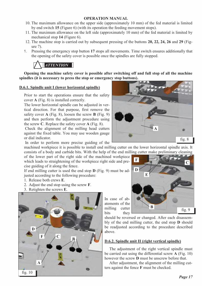
D.6.1. Spindle unit I (lower horizontal spindle)
Prior to start the operations ensure that the safety
cover A (Fig. 8) is installed correctly.
The lower horizontal spindle can be adjusted in ver-
tical direction. For that purpose, first remove the
safety cover A (Fig. 8), loosen the screw B (Fig. 9)
and then perform the adjustment procedure using
the screw C. Replace the safety cover A (Fig. 8). Check the alignment of the milling head cutters
against the fixed table. You may use wooden gauge
or dial indicator.
In order to perform more precise guiding of the
machined workpiece it is possible to install end milling cutter on the lower horizontal spindle axis. It
consists of a body and carbide bits. With the help of the end milling cutter make preliminary cleaning
of the lower part of the right side of the machined workpiece
which leads to straightening of the workpiece right side and pre-
cise guiding of it along the fence.
If end milling cutter is used the end stop D (Fig. 9) must be ad-
justed according to the following procedure:
1. Release both crews E.
2. Adjust the end stop using the screw F.
3. Retighten the screws E.
In case of ab-
atements of the
milling cutter
bits they
should be reversed or changed. After each disassem-
bly of the end milling cutter, the end stop D should
be readjusted according to the procedure described
above.
D.6.2. Spindle unit II (right vertical spindle)
The adjustment of the right vertical spindle must
be carried out using the differential screw A (Fig. 10)
however the screw D must be unscrew before that.
After adjustment, the alignment of the milling cut-
ters against the fence F must be checked.
fig. 8
A
fig. 10
A
D
F C B
E
fig. 9 B
C
D
F

MACHINE: FOUR SIDED PLANNER
TYPE: VS-20N1
OPERATION MANUAL
Page 18
D.6.3. Spindle unit III (left vertical spindle)
The desired width of the machined workpiece is achieved by side movements of the left vertical spin-
dle. This is achieved by turning the screw C (Fig. 11) and before that the handle A must be unscrewed.
The movement amount is read on the specially designed counter B.
In order to perform better guiding of the workpiece during the machining and to avoid the possible vi-
brations, a number of guiding and pressing elements are provided.
During the feeding movement before the left vertical spindle is reached, the workpiece is pressed to
the guide fence by pressing rollers. The pressing
force can be adjusted using the three handles B
(Fig. 10). Using the fourth handle C the adjust-
ment of the pressing force of the shavings separa-
tor of the left vertical spindle can be carried out.
Then, adjust the guide F (Fig. 11) located after
the left vertical spindle. To do this, the workpiece
must be stopped in the moment when it reaches
the end of the pressing plate. Unscrew the two
screws B, touch the pressing plate to the work-
piece and retighten the two screws.
D.6.4. Spindle unit IV (upper horizontal spin-
dle)
The upper horizontal spindle is installed on a
vertical guide. Horizontal bar is installed on it supporting the feeding groups. Owing to this, the reaching
the desired finished product thickness is achieved using one single adjustment by raising or lowering the
horizontal bar.
The access to the milling head is performed
by removal of the safety cover A (Fig. 12).
The height adjustment of the upper horizon-
tal spindle is carried out by turning the screw C
after the handle F is released. The moving
amount is read by the specially designed coun-
ter B.
In order to avoid possible vibrations during
the machining process, pressing elements are
provided also in this unit. These pressing ele-
ments are the following:
1. Pressing plate that presses the work-
piece before machining by the upper
rizontal spindle. The pressing force can
be adjusted by the handle D.
2. Pressing plate E that presses the fi-
nished product after machining by the
upper horizontal spindle. The plate posi-
tion is selected after releasing the two screws. We recommend that the plate plane to be at approx-
imately 0.2 mm under the milling head.
fig. 12
A
B
F C
E
D
fig. 11 A
B
F
C
B

MACHINE: FOUR SIDED PLANNER
TYPE: VS-20N1
OPERATION MANUAL
Page 19
D.6.5. Feeding group
The machine feeding system is used to
move the workpiece during the machining. It
consists of 5 motor driven shafts, 4 of which
are equipped with toothed wheels A (Fig.
13). The 5th
wheel is rubber-lined in order to
avoid damages to the finished product. The
pressing force of the feeding wheels can be
adjusted individually by 5 handles B, one for
each wheel. In some cases it is necessary the
first toothed wheel located before the lower
horizontal spindle not to take part in the
workpiece feeding. For that purpose, it can
be raised using the handle C.
D.6.6. Adjustable table and fence
The feeding table A (Fig. 14) and side
limit fence B are equipped with han-
dles for quick and easy adjustment of
the thickness of the removed layer of
material, on the lower and right sides
of the machined workpiece, respective-
ly, within 10 mm. This function of the
machine is useful for use when fre-
quent changes of workpieces of various
thicknesses of the machining allow-
ances are necessary.
The adjustment of the feeding table is performed by unscrewing the handle C, moving to the desired size
and subsequent retightening.
In similar way is carried out the adjustment of the fence by the handle D.
The amount of the machining allowance is read by the respective measuring scales. The distances be-
tween each two graduating marks are equal to approximately 1 mm. The accuracy of the measuring scales
is ensured by the precise setting of the parallelogram units used in the design. Additional setting of the
parallelogram units is carried out using eccentric sleeves only by competent and authorized persons.
D.6.7. Adjustment and installation of milling heads
WARNING
One of the most important preconditions for normal operation of the machine is to keep the good
working conditions of the milling heads. They must be very well balanced. The pairs of cutters lo-
cated opposite to each other must have equal weights and must be always replaced in pairs. The
lowest weight differences cause high vibrations to occur in the machine in case of high rotation
speeds of the spindles.
In order to be set, the milling head must be removed from the spindle using two wrenches – one is the
special wrench attached to the machine and the other wrench is 17 – 19. Then, it must be disassembled on
its components which must be cleaned carefully. The cutters and wedges must be placed on place and you
must ensure that they do not protrude laterally from the milling head body. No interchanges between the
elements of one milling head and other milling head are permissible during the reassembly works.
fig. 13
A
C
B
fig. 14
A
C
B
D

MACHINE: FOUR SIDED PLANNER
TYPE: VS-20N1
OPERATION MANUAL
Page 20
Special accessory delivered with the machine must be used to set the milling heads. This acces-
sory consists of 2 identical gauges A and B for ø120 which must be placed in the hole on both sides of the
milling head D (Fig. 15).
The adjustment must be carried out in the following order:
1. Press the cutters to get into the
milling head body and tighten them
by the end screws.
2. Place the gauges A and B (Fig.
15) in the hole on both sides of the
milling head D.
3. Release the end screws so they
must release the cutter C very slightly
and its cutter edge must touch the
gauges under the springs below the
cutter. Thus, it is ensured that the cut-
ter will rotate along diameter equal to
the gauge diameters, namely – 120
mm.
4. Tighten lightly all screws diago-
nally till normal tightness is achieved
without the use of wrench extensions.
5. Repeat steps 3 to 4 for other milling head cutters.
6. Once again check the correct tightness of all cutter screws.
7. Take out the gauges from the milling head.
Repeat the above procedure for all milling heads on machine.
ATTENTION
Using end milling cutter, check that the milling head cutters are protruded not higher than 2
mm because in such case they could touch the end milling cutter. Otherwise, readjustment of the
respective milling head is required.
Prior to the setting the cutters, ensure cleanness of the contact surfaces of the cutters and milling head.
After the setting of the milling heads, you should install them on the respective machine spindles. Re-
moval or placing the cutters before the milling is removed from the spindle is forbidden.
fig. 15 A C B
D
MACHINE: FOUR SIDED PLANNER
TYPE: VS-20N1
OPERATION MANUAL
Page 21
SECTION E: DESCRIPTION OF MACHINE
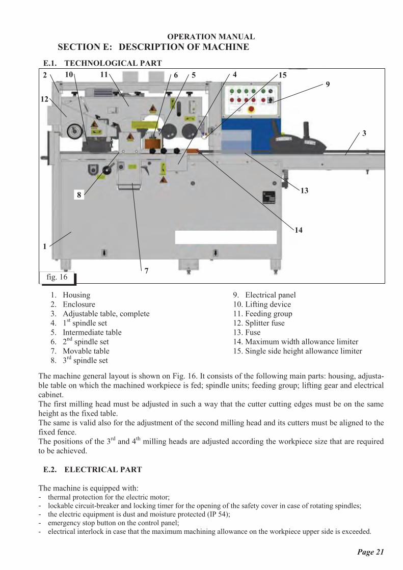
E.1. TECHNOLOGICAL PART
1. Housing
2. Enclosure
3. Adjustable table, complete
4. 1st spindle set
5. Intermediate table
6. 2nd
spindle set
7. Movable table
8. 3rd
spindle set
9. Electrical panel
10. Lifting device
11. Feeding group
12. Splitter fuse
13. Fuse
14. Maximum width allowance limiter
15. Single side height allowance limiter
The machine general layout is shown on Fig. 16. It consists of the following main parts: housing, adjusta-
ble table on which the machined workpiece is fed; spindle units; feeding group; lifting gear and electrical
cabinet.
The first milling head must be adjusted in such a way that the cutter cutting edges must be on the same
height as the fixed table.
The same is valid also for the adjustment of the second milling head and its cutters must be aligned to the
fixed fence.
The positions of the 3rd
and 4th
milling heads are adjusted according the workpiece size that are required
to be achieved.
E.2. ELECTRICAL PART
The machine is equipped with: ] thermal protection for the electric motor; ] lockable circuit-breaker and locking timer for the opening of the safety cover in case of rotating spindles; ] the electric equipment is dust and moisture protected (IP 54); ] emergency stop button on the control panel;
- electrical interlock in case that the maximum machining allowance on the workpiece upper side is exceeded.
3
fig. 16
1
2 4 5 6 11 10
7
8 13
12
15
9
14
MACHINE: FOUR SIDED PLANNER
TYPE: VS-20N1
OPERATION MANUAL
Page 22
SECTION F: MAINTENANCE
F.1. CLEANING OF MACHINE
The general (complete) cleaning will guarantee long life of the machine and is one of safety factors.
WARNING
Prior to any attempt of repair, maintenance, cleaning, etc., operations, you must disconnect the
machine power supply, and to lock the main switch by padlock.
This machine needs regular cleaning.
After each working shift:
1. Check the air suction heads of the milling spindles, working tables, recesses around the feeding
group, motor compartment and clean them from dust and machined material shavings. If the air
suction ducts are obstructed it is necessary to check the efficiency of the air suction system.
2. Clean the working place around the machine.
3. Also the hoses of air suction ducts must be removed regularly and if there are any obstructions or
collected dust these obstructions must be eliminated.
F.2.LUBRICATION OF MACHINE
Prior to commissioning the machine, start operation and especially when the machine has not been
worked for a long time it should considered the machine lubrication. Inspect carefully all the machine,
check and lubricate all points designed for that.
All bearings used in the machine are enclosed and have integrated greases, so they do not need any lubri-
cations during the whole their service life. The screw pairs of the left vertical spindle and upper horizontal
spindle as well as the guides of the lifting device of the upper horizontal spindle should be lubricated
every week using grease and the feeding group chains – two times a month. We recommend the use of
grease of one of the following types: Shell Alvania 2, Shell Alvania 3, FAG Arcanol L38, -L71, -L78 or
equal grade products.
The reduction gear lubricant must be changed at each 1000 working hours. The reduction gears must be
lubricated using transmission grade oil SAE 80, SAE 80 WEP or similar grade products.
The left vertical spindle guides must be lubricated with oil once in a week. We recommend the use of the
above oils.
Regular and careful lubrication of the above machine elements is a precondition for continuous and
seamless machine operation.
F.3.CHECKING THE CONDITION OF SOME UNITS AFTER OPERATION
The safety machine operation depends on the safety equipment described in Section B.
Before starting any maintenance works on the machine disconnect the electric supply, unplug-
ging it from the mains.
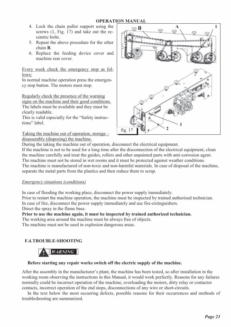
F.3.1. Chain tension
This procedure is recommended to be performed only by experienced and qualified personnel. The fol-
lowing procedure must be followed:
1. Remove the machine rear cover.
2. For tensioning the chain A unscrew the screws (1, Fig. 17) and the chain slackens.
3. Perform tensioning the chain using 2 eccentric bolts (2, Fig. 17) delivered with the machine. For
that purpose, they must be inserted in their respective holes and turned in the required direction in
order to achieve the required tension.
MACHINE: FOUR SIDED PLANNER
TYPE: VS-20N1
OPERATION MANUAL
Page 23
4. Lock the chain puller support using the
screws (1, Fig. 17) and take out the ec-
centric bolts.
5. Repeat the above procedure for the other
chain B.
6. Replace the feeding device cover and
machine rear cover.
Every week check the emergency stop as fol-
lows:
In normal machine operation press the emergen-
cy stop button. The motors must stop.
Regularly check the presence of the warning
signs on the machine and their good conditions.
The labels must be available and they must be
clearly readable.
This is valid especially for the “Safety instruc-
tions” label.
Taking the machine out of operation, storage –
disassembly (disposing) the machine.
During the taking the machine out of operation, disconnect the electrical equipment.
If the machine is not to be used for a long time after the disconnection of the electrical equipment, clean
the machine carefully and treat the guides, rollers and other unpainted parts with anti-corrosion agent.
The machine must not be stored in wet rooms and it must be protected against weather conditions.
The machine is manufactured of non-toxic and non-harmful materials. In case of disposal of the machine,
separate the metal parts from the plastics and then reduce them to scrap.
Emergency situations (conditions)
In case of flooding the working place, disconnect the power supply immediately.
Prior to restart the machine operation, the machine must be inspected by trained authorized technician.
In case of fire, disconnect the power supply immediately and use fire-extinguishers.
Direct the spray in the flame base.
Prior to use the machine again, it must be inspected by trained authorized technician.
The working area around the machine must be always free of objects.
The machine must not be used in explosion dangerous areas.
F.4.TROUBLE-SHOOTING
WARNING
Before starting any repair works switch off the electric supply of the machine.
After the assembly in the manufacturer’s plant, the machine has been tested, so after installation in the
working room observing the instructions in this Manual, it would work perfectly. Reasons for any failures
normally could be incorrect operation of the machine, overloading the motors, dirty relay or contactor
contacts, incorrect operation of the end stops, disconnections of any wire or short-circuits.
In the text below the most occurring defects, possible reasons for their occurrences and methods of
troubleshooting are summarized.
fig. 17
1 2
1 А В

MACHINE: FOUR SIDED PLANNER
TYPE: VS-20N1
OPERATION MANUAL
Page 24
Fault:
The machine does not start
Reason: Repair:
- The emergency stop button is tripped. Reset the emergency stop button through opening of
the safety cap.
- Power failure on one or more phases. Check if all 3 phases are live.
- The safety cover is open. Close the safety cover.
Fault:
The machine is stopping during the work
Reason: Repair:
- Power failure on one or more phases. Check if all 3 phases are live.
- Heavier work compared to the machine ca-
pacity (overloading). The motor thermal con-
tact is tripped.
Wait until the motor cools down.
Do not overload the machine.
Fault:
Workpiece feeding stops during work
Reason: Repair:
- The workpiece thickness is not permissible. Stop the machine and take out the workpiece.
Fault:
Workpiece lower side is curved.
Reason: Repair: - The lower horizontal spindle is lower or high-
er than the machine fixed table level.
Adjust the lower horizontal spindle till the cutters
and fixed table become even. For that purpose, use
smooth wooden block placed on the fixed table. Turn
the spindle slightly by hand and adjust it until the
cutters start to touch the wooden block slightly. (Turn
full revolution in order to find the highest cutter).
Fault:
The workpiece right side is curved.
Reason: Repair: - The limiter (D, Fig. 9) is not aligned to the
end milling cutter.
Align the limiter to the end milling cutter.
- The right vertical spindle is not aligned to the
fixed fence.
Adjust the right vertical spindle until the cutters and
fixed fence become aligned. Use wooden block and
precede as in case of adjustment the lower horizontal
spindle to the fixed table (see above).
Fault:
Curves and defects on the workpiece left side.
Reason: Removal:
- The left pressing elements and rear guide
plate (F, Fig. 11) are not adjusted.
The pressing elements on the machine left side must
be adjusted in order to press the workpiece to the
fence securely and the rear guide plate must be set
parallel to the workpiece (see Section D.6.3.).
Fault:
Curves and defects on the workpiece upper side.

MACHINE: FOUR SIDED PLANNER
TYPE: VS-20N1
OPERATION MANUAL
Page 25
Reason: Removal:
- The front or rear pressing plates of the upper
horizontal spindle are not adjusted correctly.
Adjust the front and rear pressing plates of the upper
horizontal spindle (see Section D.6.4.).
Ensure that the milling heads are adjusted perfectly using the special accessory. (The optimum position
of the cutters is when they protrude approximately 1 mm above the milling head).

MACHINE: FOUR SIDED PLANNER
TYPE: VS-20N1
OPERATION MANUAL
Page 26
SECTION G: APPENDICES
G.1. WIRING DIAGRAM AND LIST OF THE ELECTRICAL COMPONENTS

MACHINE: FOUR SIDED PLANNER
TYPE: VS-20N1
OPERATION MANUAL
Page 27
G.2. ELECTRIC CABINET – LAYOUT OF COMPONENTS

MACHINE: FOUR SIDED PLANNER
TYPE: VS-20N1
OPERATION MANUAL
Page 28
SECTION H: CATALOGUE OF SPARE PARTS
^ _ ` a b c d a e d a a d a a d a a f g h b i j k lm n o p q r m s q t s q m s q q s q q u v u w x y z w { v | } x } y o x { r ~ mp n o p q r m s q t s q q s q q s q q � � { n | { z r � } ~ � � � | } x } y o s m� ~ z r t � �BOLT М16х40
p� ~ z r t � �NUT М16
p� � o � s q t s q q s q � o s q q � v � � m� ~ z r t m pSCREW М10x25
�� � r � t p � { o � u y | m q �

MACHINE: FOUR SIDED PLANNER
TYPE: VS-20N1
OPERATION MANUAL
Page 29
� _ � d c � d a a d a a d a a � b � � j _ � � �m � o � s m � s q � s q q s q q v u � x o z ~ u mp � o � s m � s q � s q q s q q y z � � x o z ~ u m� � o � s m � s q � s q q s q q y u { y w } n u y m� � o � s m � s q � s q q s q q � y } � z v u m� � o � s m � s m q s q q s q q � � � u y � y } � z v u m� n o � p q s m � s m q s q q s q q | } n { � v u w } n u y m

MACHINE: FOUR SIDED PLANNER
TYPE: VS-20N1
OPERATION MANUAL
Page 30
^ _ ` a b c d a c d a a d a a d a a g k � � _ � g i � � � g i � � � j f � � � � �m � o � s q m s q q s q q s q p � y } � z v u mp ~ z r t m p o w y u �М 6X12
p� ~ z r � t � q o � y z r � � { o � u y p �6Н
m q� ~ z r m p � { � { o � u yАМ 6
m q� � o � s q m s q q s q q s q � { � z o p� ~ z r t m � � z � z r � o w y u �М 6 x 8
�� � o � s q m s q q s q q s q � � } ~ � p� � o � s q m s q q s q q s q � { � z o pt � o � s q m s q q s q q s p p � { o � u y pm q ~ z r � t t m o w y u �М 8Х16
pm m � o � s q m s q q s q q s m m � v { r � u pm p ~ z r t � � � } v xМ6Х20
�m � q � � q m � q � t t q � v { | z r { x u ~ � v � �ф14
pm � n o p q r m s q m s q m s q q s q q { ~ � � o x { � v u x { � v u mm � ~ z r t m p o w y u �М8х50
pm � ~ z r � t � q o � y z r � � { o � u y p �8Н
pm � n o p q r m s q m s q � s q q s q p o x } � � v } w � mm � ~ z r t � � r � xМ16
mm t n o p q r m s q m s q � s q q s q m x u r o } y mp q n o p q r m s q m s q � s q q s q � o � y z r � mp m ~ z r t � p r � xМ 8
�p p ~ z r t q p m { � { o � u y | � �p � n o p q r m s q m s q p s q q s q p � { y { v v u v } � y { | � v { x u pp � n o p q r m s q m s q p s q q s q � o � � � u y { � z o pp � n o p q r m s q m s q p s q q s q � � � o � z r � pp � ~ z r t m � � z � z r � o w y u �М 6Х16
pp � ~ z r t � � r � xМ6
�p � ~ z r t m � � z � z r � o w y u �М 6Х20
�p t n o p q r m s q m s q p s q q s q � u w w u r x y z w � � o � z r � p� q n o p q r m s q m s q p s q q s q � { � z o p� m ~ z r t m p o w y u �М8х20
p� p ~ z r � t � q o � y z r � � { o � u y p �8Н
p� � n o p q r m s q m s q p s q m s q q w } r r u w x } y m� � ~ z r t � m � } v xМ 8Х50
m� � n o p q r m s q m s q p s q q s q m o � u r w u �80Х20
m� � n o p q r m s q m s q � s q p s q q o x } � � � } ~ � m� � ~ z r t m p o w y u �М10Х20
m

MACHINE: FOUR SIDED PLANNER
TYPE: VS-20N1
OPERATION MANUAL
Page 31
� � ~ z r t m p o w y u �М10Х30
m� t n o p q r m s q m s q � s q m s q q �ЧС
u w w u r x y z w m� q n o p q r m s q m s q � s q q s q m w } r r u w x z r � y z | m� m n o p q r m s q m s q � s q q s q � { � z o m� p n o p q r m s q m s q � s q q s q � o o � u w z { v � } v xМР
m� � n o p q r m s q m s q � s q q s q � ~ z o x { r w u � � o � z r � m� � ~ z r t � � r � xМ16
m� � ~ z r t m � � z � z r � o w y u �М 6Х50
�� � ~ z r t � � r � xМ6
�� � ~ z r � t � q o � y z r � � { o � u y p �10Н
�� � ~ z r t m p o w y u �М10Х55
�� t n o p q r m s q m s q � s q q s q t � { o � u y m� q ~ z r � � � t � { o � u yМ8
m� m ~ z r t � p r � xМ 8
p� p n o p q r m s q m s q � s q � s q q �ЧС
v u n u y � � u r w u m� � n o p q r m s q m s q � s q q s q � � � o � z r � m� � n o p q r m s q m s q � s q � s q q �ЧС
v u n u y � x { � v u m� � ~ z r t � � � } v xМ10X40
m� � n o p q r m s q m s q � s q q s q � o � u w z { v � { o � u y m� � n o p q r m s q m s q � s q � s q q � { o u m

MACHINE: FOUR SIDED PLANNER
TYPE: VS-20N1
OPERATION MANUAL
Page 32
^ _ ` a b c d a � d a a d a a d a a _ � h b k � � h � j f � � � � �m n o p q r m s q � s q q s q q s q � � u v x � � v v u � � � mp n o p q r m s q � s q q s q q s q � � u v x � � v v u � � u v u w x y z w | } x } y m� u v u w x y z w | } x } y m� ~ z r t � � � } v xМ10x25
m� ~ z r � t � q o � y z r � � { o � u y p �10Н
m� � r � � p � { o � u yФ10ХФ40Х2,5
m� � u v xZ(10Х6) L=780
p� ~ z r t m � � z � z r � o w y u �М 6Х20
mt ~ z r t � � r � xМ6
mm q ~ z r � � m y z r � � } y o � { � xø
� q mm m ~ z r � � p y z r � � } y � } v uø
� � pm p y { ~ z { v � { v v � u { y z r � � q q � � � � �m � ~ z r t � � r � xМ10
mm � � o � s q � s q q s q q s m � { � z o mm � ~ z r t � � r � xМ 12
mm � ~ z r m p � { � { o � u yАМ12
�m � ~ z r m p � { � { o � u yАМ10
pm � ~ z r t m p o w y u �М10Х45
mm t ~ z r t m p o w y u �М8х25
pp q ~ z r � t � q o � y z r � � { o � u y p �8Н
pp m � o � s q � s q q s q q s q � o � v { x u mp p ~ z r m p � { � { o � u yАМ 8
�p � n o p q r m s q � s q m s q q s q m � u { y z r � � } � o z r � z mp � ~ z r � t � q o � y z r � � { o � u y p �12Н
mp � ~ z r t � � r � xМ12
mp � n o p q r m s q � s q q s q q s q � � u { y z r � � { o � u y mp � ~ z r � t t m o w y u �М 6Х16
�p � n o p q r m s q � s q m s q q s q p o � z r ~ v u z mp t n o p q r m s q � s q m s q q s q � o x } � � { o � u y m� q n o p q r m s q � s q m s q q s q � r � xМ30 L
m� m � o � s q � s q q s q q s m t o w y u � p� p ~ z r t m p o w y u �М10Х55
m� � � o � s q � s q q s q q s m � � v { x u m� � ~ z r t � � r � xМ10
m� � � o � s q � s q q s q q s p q � v � � p� � � o � s q � s q q s q q s p m { � z o m� � � o � s q � s q q s q q s p p � � o � z r � m� � ~ z r � � � � { w } x x u yА8Х7Х20
m

MACHINE: FOUR SIDED PLANNER
TYPE: VS-20N1
OPERATION MANUAL
Page 33
^ _ ` a b c d a � d a a d a a d a a h b � � � f � k h g � � � g i � �m ~ z r t m p o w y u �М8Х45
�p ~ z r � t � q o � y z r � � { o � u y p �8Н
m q� n o p q r m s q � s q q s q q s q m x { � v u z z m� ~ z r m � � m o � y z r � � z rФ 6Х50
p� � o � s q � s q q s q q s q � � v } w � m� � o � s q � s q q s q q s q � { � z o m� ~ z r t m p o w y u �М8х55
�� ~ z r t � � r � xМ 12
mt ~ z r m p � { � { o � u yАМ12
�m q � o � s q � s q q s q q s q � { � z o mm m � o � s q � s q q s q q s � q o w y u � mm p � o � s q � s q q s q q s m t o w y u � pm � � o � s q � s q q s q q s p q � v � � pm � ~ z r m p � { � { o � u yАМ 8
mm � � o � s q � s q q s q q s p � � v { x u mm � ~ z r t � � r � xМ8
mm � � o � s q � s q q s q q s � � y � � � u y mm � � o � s q � s q q s q q s � � � v { x u mm t ~ z r � � q y � { o � u y | � pp q ~ z r m p � { � { o � u yАМ 6
pp m n o p q r m s q � s q p s q q s q q � y } x u w x } y mp p n o p q r m s q � s q q s q q s q p w } n u y mp � � m � � � � q | q � � p q � { r ~ v u o x { yМ6Х20
pp � ~ z r m p � { � { o � u yАМ 4
pp � ~ z r t m p o w y u �М 4x10
p

MACHINE: FOUR SIDED PLANNER
TYPE: VS-20N1
OPERATION MANUAL
Page 34
p � ~ z r m � � m o � y z r � � z rФ 6Х20
pp � ~ z r t m p o w y u �М8х16
�p � ~ z r t m p o w y u �М 6Х20
pp t ~ z r � t � q o � y z r � � { o � u y p �6Н
p
^ _ ` a b c d a � d a a d a a d a a _ � h b k � � h h � j f � � � � �m n o p q r m s q � s q q s q q s q � � u v x � � v v u � � u v u w x y z w | } x } y mp n o p q r m s q � s q q s q q s q � � u v x � � v v u � � � m� u v u w x y z w | } x } y m� ~ z r t � � � } v xМ10Х25
m� ~ z r � t � q o � y z r � � { o � u y p �10Н
m� � r � � p � { o � u yФ10ХФ40Х2,5
m� � u v xZ(10Х6) L=930
p� ~ z r t m � � z � z r � o w y u �М 6Х20
mt ~ z r t � � r � xМ6
mm q ~ z r � � m y z r � � } y o � { � x � q mm m ~ z r � � p y z r � � } y � } v uФ68
pm p y { ~ z { v � { v v � u { y z r � � q q � � � � �m � n o p q r m s q � s q q s q q s q m � u { y z r � � } � o z r � � z z mm � n o p q r m s q � s q q s q q s q � � u { y z r � � { o � u y mm � ~ z r � t t m o w y u �М 6Х16
�m � n o p q r m s q � s q q s q q s q � o x } � � { o � u y mm � ~ z r � � � � { w } x x u yА8Х7Х20
mm � n o p q r m s q � s q q s q q s q � � { o � u y mm t n o p q r m s q � s q q s q q s q p o � z r ~ v u �В. II
mp q n o p q r m s q � s q q s q q s m q r � xМ30x2
m

MACHINE: FOUR SIDED PLANNER
TYPE: VS-20N1
OPERATION MANUAL
Page 35
^ _ ` a b c d a � _ d a a d a a d a a � g i � � f j ^ g i � �m n o p q r m s q � s q � s q q s q q o { � u x � w } n u y mp ~ z r m p � { � { o � u yМ6
�� � r � t p � { o � u yМ6
�� ~ z r t m p o w y u �М 6X12
�� � o � s q � s q q s q m s q q w } n u y m�DА0912
� � s q u � p q � � w | } n { � v u m� ~ z r � t t m o w y u �М 6X20
�� v � � m �32 M8Х20
� v � � { r ~ v u mt ~ z r t � � r � xМ8
mm q ~ z r t � � � } v xМ8x45
mm m n o p q r m s q � s q q s q q s q m x { � v u | } n { � v u } r n u y x z w { v o � z r ~ v u mm p ~ z r m � � m o � y z r � � z rФ 6Х50
pm � ~ z r t m p o w y u �М8х20
�m � � r � t p � { o � u yМ8
m �m � { � � p q � � { � z { v r u u ~ v u � u { y z r � p

MACHINE: FOUR SIDED PLANNER
TYPE: VS-20N1
OPERATION MANUAL
Page 36
m � � o � m m q � { � z { v � { o � u y20х35х2.75
pm � � o � s q � s q q s q q s p t o � { o � u y mm � � o � s q � s q q s q q s p � o � } ~ � mm t { o p q � � { � z { v � { o � u yФ20х35х1
pp q � o � s q � s q q s q q s q � o o o w y u � mp m n o p q r m s q � s q q s q q s � m o r � x x � p � � mp p � r � � p � { o � u yф8хф30х2
mp � ~ z r m p � { � { o � u yАМ 8
pp � ~ z r t m p o w y u �М8Х45
pp � n o p q r m s q � s q q s q q s � � o � � u u v pp � � o � s q � s q q s q q s � p o � u w z { v o w y u � �p � ~ z r t � � � } v xМ8x20
pp � n o p q r m s q � s q q s q q s � m o { y | pp t � o � s q � s q q s q q s � � � � o � z r � p� q n o p q r m s q � s q q s q q s � p o x u r o z } r v u n u y �� m ~ z r m � � � { o � u y | � m �� p ~ z r t m � � z � z r � o w y u �М 8Х30
�� � ~ z r t � � r � xМ 8
�� � y { ~ z { v � { v v � u { y z r � � q q q � � � �� � � o � s q � s q q s q q s � � � � u u v m� � n o p q r m s q � s q q s q q s � � o { y | m� � ~ z r t � � � { o � u yФ14ХФ20Х0.5
m� � ~ z r t � � � { o � u yФ14ХФ20Х1
m� t n o p q r m s q � s q q s q q s � � o o � u w z { v r � x �� q ~ z r m p � { � { o � u yМ6
�� m � o � s q � s q q s q q s � � � � o � z r � m� p ~ z r t � � r � xМ 6
p� � � o � s q � s q q s q q s q � y z | m� � � o � s q � s q q s q q s m t o � y z r � �� � n o p q r m s q � s q � s q q s q q o x } � m� � ~ z r t � � r � xМ6
�� � � o � s q � s q q s q � s q q � { r ~ v u �� � n o p q r m s q � s q m o s q q s q q � � y } v v u y w } n u y m� t � r m p � � � { o � u y | � p� q ~ z r � t t m o w y u �М 8х20
p� m ~ z r � � q y � { o � u y | � p� p n o p q r m s q � s q p s q q s q q � y } x u w x } y m� � ~ z r t m p o w y u �М8х55
p� � ~ z r t � � � } v xМ6Х30
�� � n o p q r m s q � s q q s q q s � � o o v z | z x u y m� � ~ z r t � � � } v xМ6Х25
p� � � o � s q � s q q s q p s q q o x } � m� � ~ z r t � � � } v xМ8х25
m

MACHINE: FOUR SIDED PLANNER
TYPE: VS-20N1
OPERATION MANUAL
Page 37
^ _ ` a b c d a ¡ d a a d a a d a a _ � h b k � � h h h � j f � � � � �m n o p q r m s q � s q q s q q s q � � u v x � � v v u � � u v u w x y z w | } x } y mp n � � u v x � v ¢ m m p q p� ~ z r t � � r � xМ6
m� ~ z r t m � � z � z r � o w y u �М 6Х20
m� ~ z r t m p o w y u �М8х25
�� ~ z r m � � � { o � u y | � �� ~ z r t � � r � xМ8
pt n o p q r m s q � s q p o s q p s q q v } � u y o � � � } y x mm q n o p q r m s q � s q p o s q m s q q � � � u y o � � � } y xIII К
�Т
mm m ~ z r t m � � z � z r � o w y u �М 8x60
pm p u v u w x y z w | } x } y mm � � r � t p � { o � u yМ8
�m � � r � t p � { o � u yМ8
�m � ~ z r m p � { � { o � u y | � �m � ~ z r t � � � } v xМ8x20
�m � ~ z r t � � � } v xМ10x25
mm � � r � t p � { o � u y | m q mm � � r � � p � { o � u yФ10ХФ40Х2,5
mm t n o p q r m s q � s q q s q q s q � � u v x � � v v u � � � mp q ~ z r t m p o w y u �М10x25
�p m � r � t p � { o � u y | m q �p p ~ z r � � m y z r � � } y o � { � x � q mp � n o p q r m s q � s q m s q q s q m � u { y z r � � } � o z r � z z z mp � n o p q r m s q � s q q s q q s q � � u { y z r � � { o � u y mp � ~ z r � t t m o w y u �М 6Х16
�p � n o p q r m s q � s q q s q q s q � o x } � � { o � u y mp � n o p q r m s q � s q q s q q s q � � { o � u y mp � n o p q r m s q � s q m s q q s q p o � z r ~ v u z z z mp t n o p q r m s q � s q m s q q s q � r � xМ30 L
m� q ~ z r � � � � { w } x x u yА8Х7Х20
m� m y { ~ z { v � { v v � u { y z r � � q q � � � � �� p ~ z r � � p y z r � � } y � } v uФ68
p� � ~ z r t � � � } v xМ 8Х30
�� � ~ z r t � � r � xМ12
�� � n o p q r m s q � s q q s q q s q m o x � ~М12 L=195
p� � ~ z r m p � { � { o � u y | m p �

MACHINE: FOUR SIDED PLANNER
TYPE: VS-20N1
OPERATION MANUAL
Page 38
^ _ ` a b c d c � _ d a a d a a d a a � � ^ � � � h b £ k � ^ h � �m n o p q r m s m � s q q s q q s q m o w { y y z { � u �Н
mp p � � p v z � { o o � y z r � m� ~ z r t m p o w y u �М10x70
�� � r � t p � { o � u y | m q �� n o p q r m s m � s q q s q q s � q o o � � � } y x m� n o p q r m s m � s q q s q q s � � o � v { x u m� n o p q r m s m � s q q s q q s � � o � v { x u m� � o � p r s m q s q q s q � � v { r � u mt n o p q r m s m � s � m o s q q s q q w v { | � z r � v u n u y mm q z o } � � � q o w y u �М6Х20
pm m � r � t p � { o � u yМ6
�m p n o p q r m s m � s � q o s q q s q q y u { y v u n u v v z r � mm � � o � s m � s q q s q q s q p � u ~ � u mm � ~ z r t m � � z � z r � o w y u �М 8Х30
�m � ~ z r t � � r � xМ8
�m � ~ z r t m p o w y u �М 6Х25
pm � n o p q r m s m � s q q s q q s q p o x } � mm � ~ z r t m � � z � z r � o w y u �М10x80
mm t ~ z r t � � r � xМ10
mp q n � � u v x � v ¢ � � q pp m ~ z r t � � � } v xМ8х25
�p p � r � t p � { o � u yМ8
�p � � r � � p � { o � u yф8хф30х2
�p � n o p q r m s m � s q p s q m s q q o � � � } y x u v u w x y z w | } x } y s z n mp � u v u w x y z w | } x } y mp � � r � t p � { o � u yМ8
�p � ~ z r t � � � } v xМ8x20
�p � n o p q r m s q � s q q s q q s q � � u v x � � v v u � � u v u w x y z w | } x } y mp t ~ z r t m � � z � z r � o w y u �М 6Х20
m� q ~ z r t � � r � xМ6
m^ _ ` a b c d c � d a c d a a d a a _ � h b k � � h ^ ¤Н� m ~ z r t � � � } v x
М10x25m� p � r � t p � { o � u y | m q m

MACHINE: FOUR SIDED PLANNER
TYPE: VS-20N1
OPERATION MANUAL
Page 39
� � � r � � p � { o � u yФ10ХФ40Х2,5
m� � n o p q r m s q � s q q s q q s q � � u v x � � v v u � � � m� � ~ z r � � m y z r � � } y o � { � x � q m� � ~ z r � � p y z r � � } y � } v uФ68
p� � y { ~ z { v � { v v � u { y z r � � q q � � � � �� � n o p q r m s m � s q m s q q s q m � u { y z r � � } � o z r � z n m� t � r � t p � { o � u yМ8
�� q � o � s q � s q q s q q s p q � v � � m� m � o � s q � s q q s q q s m t o w y u � m� p ~ z r � � � � { w } x x u yА8Х7Х20
m� � n o p q r m s q � s q q s q q s q � � u { y z r � � { o � u y m� � n o p q r m s m � s q m s q q s q � o o x } � � { o � u y m� � n o p q r m s q � s q q s q q s m q r � xМ30x2
m� � ~ z r � t t m o w y u �М 6Х16
�� � n o p q r m s m � s q m s q q s q p o � z r ~ v u z n m� � ~ z r t m p o w y u �М8х25
�
^ _ ` a b c d c � d � a _ d a a d a a � � ^ � � � h b £m ~ ~ � p � { r � q q p s � � ~ � � y w } � r x u y mp z o } � � � q o w y u �М6Х20
�� � r � t p � { o � u yМ6
�� n o p q r m s m � s � q o s q q s m t z r ~ z w { x } y � v { x u m� n o p q r m s m � s � q o s q q s m � y u { y � v { x u m� n o p q r m s m � s � q o s q q s m � � u { y z r � o � � � } y x m� n o p q r m s m � s � q o o s q q s m � o � { � x m� ~ z r m � � m o � y z r � � z rф8х40
pt n o p q r m s m � s � q o s q q s q m w } r o } v u mm q � r � t p � { o � u yМ8
�m m n o p q r m s m � s � q o s q q s q � o x � ~ m

MACHINE: FOUR SIDED PLANNER
TYPE: VS-20N1
OPERATION MANUAL
Page 40
m p ~ z r t � � r � xМ10
�m � n o p q r m s m � s � q o s q q s q t v u n u v v z r � r � xТр24x5
mm � n o p q r m s m � s � q o s q q s q � o w y u � mm � ~ z r t m p o w y u �М8х40
�m � n o p q r m s m � s � q o s q q s q p o � � � } y x mm � ~ z r � � � � { w } x x u y6х6х18
mm � ~ z r t m � � z � z r � o w y u �М 8x35
mm t ~ z r t � � r � xМ8
mp q � r � t p � { o � u y | m q �p m ~ z r t m p o w y u �М10x80
�p p � { � p q p q � m q � � o � z r � pp � { � z { v � { v v � u { y z r � � m m q � ¥ � m q � mp � { o p q � � { � z { v � { o � u yФ20х35х1
pp � n o p q r m s m � s � q o s q q s p p � � u u v � u { y � ¢ p p mp � n o p q r m s m � s � q o s q q s p � � � � u y w } n u y mp � z o } � � � q o w y u �М 5Х 8
�p � ~ z r t � � r � xМ16
mp t ~ z r m � � � { o � u y | m � m� qДМ5
� � q m s � m s m q s q � � � u u v � u { y � ¢ m m m� m ~ z r m � � m o � y z r � � z rФ6х36
m� p n o p q r m s m � s � q o s q q s p t o z ~ u w } n u y m
MACHINE: FOUR SIDED PLANNER
TYPE: VS-20N1
OPERATION MANUAL
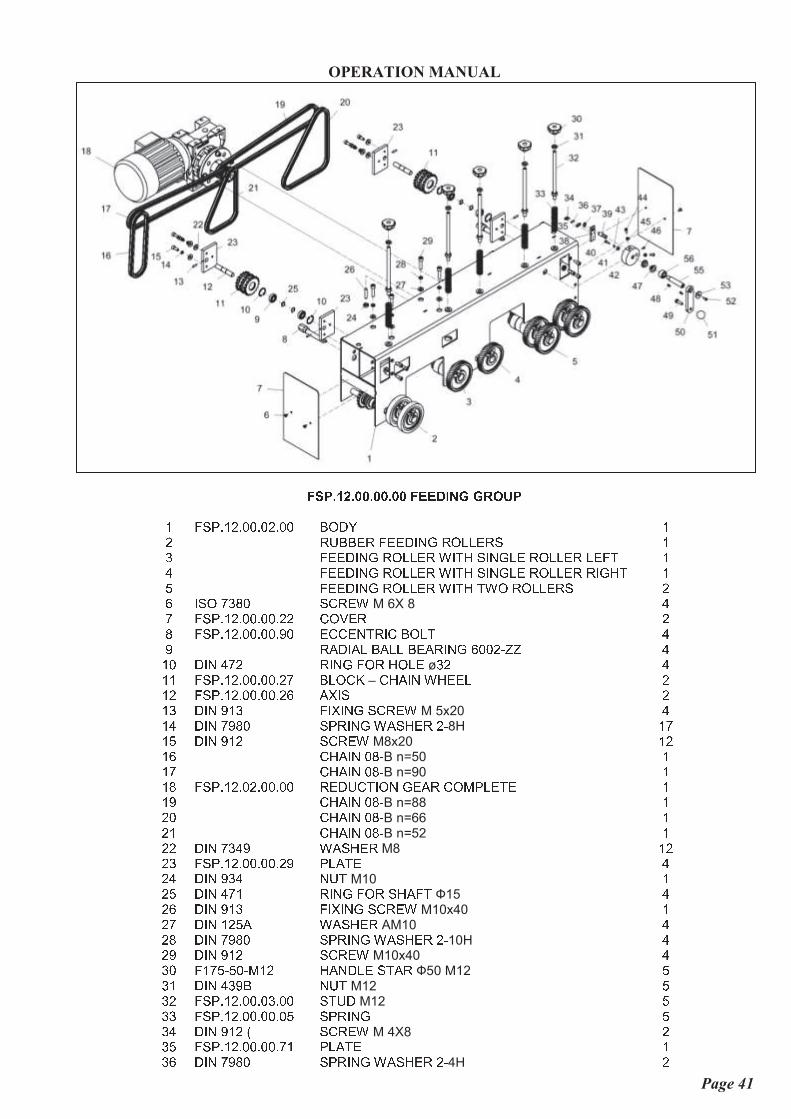
Page 41
� _ � d c ` d a a d a a d a a � � � k h b £ £ � j � �m � o � s m p s q q s q p s q q � } ~ � mp y � � � u y � u u ~ z r � y } v v u y o m� � u u ~ z r � y } v v u y � z x � o z r � v u y } v v u y v u � x m� � u u ~ z r � y } v v u y � z x � o z r � v u y } v v u y y z � � x m� � u u ~ z r � y } v v u y � z x � x � } y } v v u y o p� z o } � � � q o w y u �М 6Х 8
�� � o � s m p s q q s q q s p p w } n u y p� � o � s m p s q q s q q s t q u w w u r x y z w � } v x �t y { ~ z { v � { v v � u { y z r � � q q p � � � �m q ~ z r � � p y z r � � } y � } v uø
� p �m m � o � s m p s q q s q q s p � � v } w �–
w � { z r � � u u v pm p � o � s m p s q q s q q s p � { � z o pm � ~ z r t m � � z � z r � o w y u �М 5x20
�m � ~ z r � t � q o � y z r � � { o � u y p �8Н
m �m � ~ z r t m p o w y u �М8х20
m pm � w � { z r q � �В n=50
mm � w � { z r q � �В n=90
mm � � o � s m p s q p s q q s q q y u ~ � w x z } r � u { y w } | � v u x u mm t w � { z r q � �В n=88
mp q w � { z r q � �В n=66
mp m w � { z r q � �В n=52
mp p ~ z r � � � t � { o � u yМ8
m pp � � o � s m p s q q s q q s p t � v { x u �p � ~ z r t � � r � xМ10
mp � ~ z r � � m y z r � � } y o � { � xФ15
�p � ~ z r t m � � z � z r � o w y u �М10x40
mp � ~ z r m p � { � { o � u yАМ10
�p � ~ z r � t � q o � y z r � � { o � u y p �10Н
�p t ~ z r t m p o w y u �М10x40
�� q � m � � � � q � | m p � { r ~ v u o x { yФ50 М12
�� m ~ z r � � t � r � xМ12
�� p � o � s m p s q q s q � s q q o x � ~М12
�� � � o � s m p s q q s q q s q � o � y z r � �� � ~ z r t m p ¦ o w y u �М 4Х8
p� � � o � s m p s q q s q q s � m � v { x u m� � ~ z r � t � q o � y z r � � { o � u y p �4Н
p
MACHINE: FOUR SIDED PLANNER
TYPE: VS-20N1
OPERATION MANUAL
Page 42
� � ~ z r � � m y z r � � } y o � { � xФ12
m� � � o � s m p s q q s q q s � p � v { x u m� t � o � s m p s q q s q q s � t { � z o m� q ~ z r t m p o w y u � | � � m � m� m ~ z r � � � t � { o � u yМ 5
m� p � o � s m p s q q s q q s � � u w w u r x y z w m� � ~ z r � t � q o � y z r � � { o � u y p � � � m� � z o } � � � q o w y u �М6Х16
p� � ~ z r t � � r � xМ6
p� � ~ z r � t t m o w y u �М 4х10
m� � � o � s m p s q q s q q s � q � � o � z r � p� � ~ z r � � � � { w } x x u y4Х4Х14
p� t ~ z r t � � � } v xМ8х25
m� q � o � s m p s q q s q q s � � � { r ~ v u m� m z m q � � q s x | q � q m � { r ~ v u � { v vФ30 М8
m� p ~ z r � t t m o w y u �М 5Х16
m� � � o � s m p s q q s q q s � � � { o � u y m� � � o � s m p s q q s q q s � t { � z o m� � � o � s m p s q q s q q s � � ~ z o x { r w u � � o � z r � m
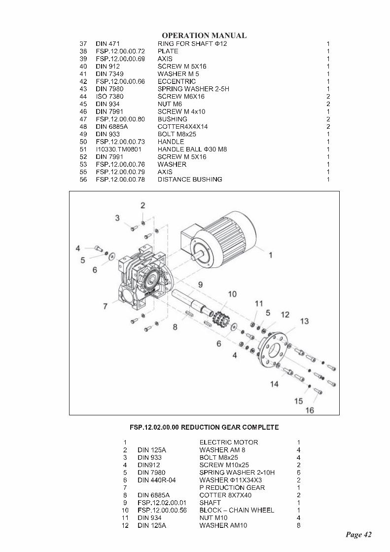
� _ � d c ` d a ` d a a d a a � � k � � � h j b £ � g � � j f � � � � �m u v u w x y z w | } x } y mp ~ z r m p � { � { o � u yАМ 8
�� ~ z r t � � � } v xМ8х25
�� ~ z r t m p o w y u �М10x25
p� ~ z r � t � q o � y z r � � { o � u y p �10Н
�� ~ z r � � q y � q � � { o � u yФ11Х34Х3
p�Р
y u ~ � w x z } r � u { y m� ~ z r � � � � { w } x x u y8Х7Х40
pt � o � s m p s q p s q q s q m o � { � x mm q � o � s m p s q q s q q s � � � v } w �–
w � { z r � � u u v mm m ~ z r t � � r � xМ10
�m p ~ z r m p � { � { o � u yАМ10
�

MACHINE: FOUR SIDED PLANNER
TYPE: VS-20N1
OPERATION MANUAL
Page 43
m � � o � s m p s q p s q q s q t � v { r � u mm � ~ z r t m p o w y u �М10х35
�m � ~ z r � t � q o � y z r � � { o � u y p �8Н
�m � ~ z r t m p o w y u �М8х30
�
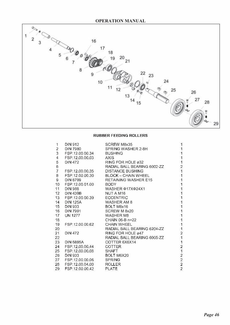
� � � k h b £ � j � � � � § h � ¨ � § j � j � � � � _m ~ z r t m p o w y u �М8х35
mp ~ z r � t � q o � y z r � � { o � u y p �8Н
m� � o � s m p s q q s q q s � � � � o � z r � m� � o � s m p s q q s q q s q � { � z o m� ~ z r � � p y z r � � } y � } v u � p m� y { ~ z { v � { v v � u { y z r � � q q p � � � p� � o � s m p s q q s q q s � � ~ z o x { r w u � � o � z r � m� � o � s m p s q q s q q s � q � v } w �–
w � { z r � � u u v mt ~ z r � � t t y u x { z r z r � � { o � u yЕ15
mm q � o � s m p s q q s q m s q q � } ~ � mm m ~ z r t � � � { o � u yФ17ХФ24Х1
mm p ~ z r � � t � r � x | m � mm � ~ z r � t t m o w y u �М 8х20
mm � � r m p � � � { o � u y | � mm � � o � s m p s q q s q q s � p w � { z r � � u u v mm � y { ~ z { v � { v v � u { y z r � � p q � � � � mm � ~ z r � � p y z r � � } y � } v u � � pm � y { ~ z { v � { v v � u { y z r � � q q � � � � mm t � o � s m p s q q s q q s q � o � { � x mp q ~ z r � � � � { w } x x u y6Х6Х14
mp m � o � s m p s q q s q q s � � w } x x u y pp p � o � s m p s q q s q q s � � � u u ~ z r � y } v v u y pp � ~ z r t � � � } v xМ6Х20
pp � � o � s m p s q q s q q s q � o � y z r � pp � � o � s m p s q q s q q s � p � v { x u p

MACHINE: FOUR SIDED PLANNER
TYPE: VS-20N1
OPERATION MANUAL
Page 44
� � � k h b £ � j � � � � § h � ¨ _ h b £ � � � j � � � � � � � �m ~ z r t m p o w y u �М8х35
mp ~ z r � t � q o � y z r � � { o � u y p �8Н
m� � o � s m p s q q s q q s � � � � o � z r � m� � o � s m p s q q s q q s q � { � z o m� ~ z r � � p y z r � � } y � } v u � p m� y { ~ z { v � { v v � u { y z r � � q q p � � � p� � o � s m p s q q s q q s � � ~ z o x { r w u � � o � z r � m� � o � s m p s q q s q q s � q � v } w �–
w � { z r � � u u v mt ~ z r � � t t y u x { z r z r � � { o � u yЕ15
mm q � o � s m p s q q s q m s q q � } ~ � mm m ~ z r t � � � { o � u yФ17ХФ24Х1
mm p ~ z r � � t � r � x | m � mm � ~ z r � t t m o w y u �М 8х20
mm � � r m p � � � { o � u y | � mm � w � { z r q � �В n=22
mm � � o � s m p s q q s q q s � p w � { z r � � u u v mm � y { ~ z { v � { v v � u { y z r � � p q � � � � mm � ~ z r � � p y z r � � } y � } v u � � pm t � o � s m p s q q s q q s � t u w w u r x y z w mp q ~ z r m p � { � { o � u yАМ 8
mp m ~ z r t � � � } v xМ8x16
mp p y { ~ z { v � { v v � u { y z r � � q q � � � � mp � ~ z r � � � � { w } x x u y6Х6Х14
mp � � o � s m p s q q s q q s � � w } x x u y mp � � o � s m p s q q s q q s � � o � { � x mp � � o � s m p s q q s q q s � � � u u ~ z r � y } v v u y mp � ~ z r t � � � } v xМ6Х20
mp � � o � s m p s q q s q q s q � o � y z r � mp t � o � s m p s q q s q q s � p � v { x u m

MACHINE: FOUR SIDED PLANNER
TYPE: VS-20N1
OPERATION MANUAL
Page 45
� � � k h b £ � j � � � � § h � ¨ _ h b £ � � � j � � � � � h £ ¨ �m ~ z r t m p o w y u �М8х35
mp ~ z r � t � q o � y z r � � { o � u y p �8Н
m� � o � s m p s q q s q q s � � � � o � z r � m� � o � s m p s q q s q q s q � { � z o m� y { ~ z { v � { v v � u { y z r � � q q p � � � p� � o � s m p s q q s q q s � � ~ z o x { r w u � � o � z r � m� ~ z r � � p y z r � � } y � } v u � p m� � o � s m p s q q s q q s � q � v } w �–
w � { z r � � u u v mt ~ z r � � t t y u x { z r z r � � { o � u yЕ15
mm q � o � s m p s q q s q m s q q � } ~ � mm m ~ z r t � � � { o � u yФ17ХФ24Х1
mm p ~ z r � � t � r � x | m � mm � � o � s m p s q q s q q s � t u w w u r x y z w mm � ~ z r m p � { � { o � u yАМ 8
mm � ~ z r t � � � } v xМ8x16
mm � ~ z r � t t m o w y u �М 8х20
mm � � r m p � � � { o � u y | � mm � w � { z r q � �В n=22
mm t � o � s m p s q q s q q s � p w � { z r � � u u v mp q y { ~ z { v � { v v � u { y z r � � p q � � � � mp m ~ z r � � p y z r � � } y � } v u � � pp p y { ~ z { v � { v v � u { y z r � � q q � � � � mp � ~ z r � � � � { w } x x u y6Х6Х14
mp � � o � s m p s q q s q q s � � w } x x u y mp � � o � s m p s q q s q q s � � � u u ~ z r � y } v v u y mp � ~ z r t � � � } v xМ6Х20
mp � � o � s m p s q q s q q s q � o � y z r � mp � � o � s m p s q q s q q s � p � v { x u mp t � o � s m p s q q s q q s � � o � { � x m
MACHINE: FOUR SIDED PLANNER
TYPE: VS-20N1
OPERATION MANUAL
Page 46
� � i i � � � � � k h b £ � j � � � � _m ~ z r t m p o w y u �М8х35
mp ~ z r � t � q o � y z r � � { o � u y p �8Н
m� � o � s m p s q q s q q s � � � � o � z r � m� � o � s m p s q q s q q s q � { � z o m� ~ z r � � p y z r � � } y � } v uø32
m� y { ~ z { v � { v v � u { y z r � � q q p � � � p� � o � s m p s q q s q q s � � ~ z o x { r w u � � o � z r � m� � o � s m p s q q s q q s � q � v } w �–
w � { z r � � u u v mt ~ z r � � t t y u x { z r z r � � { o � u yЕ15
mm q � o � s m p s q q s q m s q q � } ~ � mm m ~ z r t � � � { o � u yФ17ХФ24Х1
mm p ~ z r � � t � r � xА M16
mm � � o � s m p s q q s q q s � t u w w u r x y z w mm � ~ z r m p � { � { o � u yАМ 8
mm � ~ z r t � � � } v xМ8x16
mm � ~ z r � t t m o w y u �М 8х20
mm � � r m p � � � { o � u y | � mm � w � { z r q � �В n=22
mm t � o � s m p s q q s q q s � p w � { z r � � u u v mp q y { ~ z { v � { v v � u { y z r � � p q � � � � mp m ~ z r � � p y z r � � } y � } v uø47
pp p y { ~ z { v � { v v � u { y z r � � q q � � � � mp � ~ z r � � � � { w } x x u y6Х6Х14
mp � � o � s m p s q q s q q s � � w } x x u y pp � � o � s m p s q q s q q s q � o � { � x mp � ~ z r t � � � } v xМ6Х20
pp � � o � s m p s q q s q q s q � o � y z r � pp � � o � s m p s q q s q � s q q y } v v u y pp t � o � s m p s q q s q q s � p � v { x u p