operation manual water softener geno-mat wf · this operation manual is intended for the operators...
TRANSCRIPT
Operation manualWater Softener GENO-mat® WF
Edit ion January 2009 Order no. 084 182 041-inter

Content
Order no. 024 182 940-gb Edited by: KONS-mpö-rg G:\BA-182940-GB-DECKBL.DOC
1
Table of contents
This operation manual consists of several parts which are listed in the index below. With regard to more detailed information, please refer to the cover sheets of the individual parts.
General ....................................................................
Basic information* ....................................................
Product description ...................................................
Installation ................................................................
Start-up ....................................................................
Operation .................................................................
Troubleshooting ........................................................
Maintenance .............................................................
Attachments: List of Grünbeck representatives
A
B
C
D
E
F
G
H
Publisher’s information
All rights reserved.
Copyright by Grünbeck Wasseraufbereitung GmbH
Printed in Germany Effective with the date shown on the cover sheet. – We reserve the right to modification, especially with regard to technical progress -
Reprints, translations into foreign languages, electronic storage or copying only with written approval of Grünbeck Wasseraufbereitung GmbH.
Any type of duplication not authorised by Grünbeck Wasseraufbereitung is a copyright violation and subject to legal action.
Responsible for contents: Grünbeck Wasseraufbereitung GmbH Industriestrasse 1 89420 Hoechstaedt/Germany Phone +49 9074 41-0 Fax +49 9074 41-100 www.gruenbeck.de [email protected]
Print: Grünbeck Wasseraufbereitung GmbH Industriestrasse. 1, 89420 Hoechstaedt/Germany

Declaration of Conformity
Order no. 024 182 940-gb Edited by: KONS-mpö-rg G:\BA-182940-GB-DECKBL.DOC
2
EC Declaration of Conformity
This is to certify that the system designated below meets the safety and health requirements of the applicable European guidelines in terms of its design, construction and execution.
If the system is modified in a way not approved by us, this certificate is void.
System Designation: GENO-mat®
System Type: WF
System No.: refer to type designation plate
Applicable EC Guidelines: EC Guideline EMV (89/336/ECC, version 92/31/ECC) EC Low Voltage Guideline (2006/95/EC)
Applied harmonized standards, in particular:
DIN EN 50 081-1, DIN EN 50 082-2, 1st Guideline on Device and Product Safety (Ordinance on the Marketing of Electrical Operating Materials to be used within specific voltage limits – 1. GPSGV).
Applied national standards and technical specifications, in particular:
DIN 1988, DIN 19 636 (07.89) DIN 31000/VDE 1000 (03.79)
Date / Signature of manufacturer:
11.08.11 i. V. M. Pöpperl Dipl.-Ing. (FH)
Function of signatory: Head of Engineering Department for Serial Products
General
Order no. 064 181 949-gb Edited by: KONS-mpö-rg G:\BA-181949-GB_A.DOC
A-1
A General
Table of contents
1 | Preface ........................................................................ 2 | Warranty ..................................................................... 3 | How to use this operation manual .............................. 4 | General safety information ..........................................
4.1 Symbols and notes ................................................ 4.2 Operating personnel ............................................. 4.3 Designated application.......................................... 4.4 Protection from water damage ............................. 4.5 Indication of specific dangers ................................
5 | Shipping and storage .................................................. 6 | Disposal of used parts and materials ...........................
A-1 A-2 A-2 A-3 A-3 A-3 A-3 A-4 A-4 A-4 A-4
1 | Preface
Thank you for opting for a Grünbeck product. Backed by decades of experience in the area of water treatment, we provide solutions for all kind of processes.
Drinking water is classified as food and requires particular care. There-fore, always ensure the required hygiene in operating and maintain-ing systems for drinking water treatment. This also applies to the treatment of water for industrial use if repercussions for the drinking water cannot completely be excluded.
All Grünbeck systems and devices are made of high-quality materi-als. This ensures reliable operation over many years, provided you treat the systems with the required care. This operation manual assists you with important information. Therefore, read the com-plete manual before installing, operating or maintaining your sys-tem.
Customer satisfaction is our prime objective and providing cus-tomers with qualified advice is crucial. If you have any questions concerning this system, possible extensions or general water and waste water treatment, our technical service staff, as well as the experts at our headquarters in Hoechstaedt, is available to help you.
Advice and assistance For advice and assistance please contact your local representative (refer to the enclosed list) or get in touch with our service centre which can be reached during office hours:
Tel.: +49 9074 41-333 Fax: +49 9074 41-120 Email: [email protected]
We can connect you with the appropriate expert more quickly if you provide the required system data. In order to have access to this data at all times, please fill in the data given on the type des-ignation plate into the table on page C-1.

General
Order no. 064 181 949-gb Edited by: KONS-mpö-rg G:\BA-181949-GB_A.DOC
A-2
2 | Warranty
All devices and systems supplied by Grünbeck Wasseraufbereitung GmbH are manufactured according to the most recent technical standards and subjected to a comprehensive quality assurance system. All warranty claims are subject to our General Terms and Conditions (see excerpt below):
Terms and Conditions of Sale and Delivery (excerpt)
. . . . . . . .
11. Warranty
a) If goods and services are supplied which are obviously defective, the Customer must report such defects within 8 (eight) days after receipt of such goods and services in order to maintain the liability claims.
b) If the defect is of such a nature that only a spare part needs to be replaced, Grünbeck shall have the right to request the Purchaser to replace the new part delivered by us if the costs for sending a technician to the Pur-chaser's site are unreasonably high.
c) The warranty periods are:
- two years: for devices for private use (natural per-sons)
- one year: for devices for industrial or commercial use (companies)
- two years: for all DVGW-certified devices, also for industrial or commercial use within the framework of the liability agreement with the ZVSHK.
after delivery/acceptance. This excludes electrical parts and parts which are subject to wear and tear. The war-ranty period shall only apply if the operating instruc-tions are observed meticulously, if the device is mount-ed, commissioned, operated and maintained properly, and/or if a maintenance contract is made within six months. If these requirements are not met, the warran-ty shall be void. The warranty shall be void if the pur-chaser uses dosing agents or chemicals supplied by other manufacturers and if the quality and composition
of such dosing agents or chemicals is beyond Grünbeck's control. Grünbeck shall not be liable for defects or dam-age resulting from inept handling or operation.
d) Grünbeck shall only be liable if the Customer performs the maintenance work as stated in the operating instruc-tions or has the maintenance work performed in such a way and if the Customer uses spare parts supplied or recommended by Grünbeck.
e) Grünbeck shall not be liable for damage resulting from frost, water or electrical over-voltage or from parts which are subject to wear and tear. This applies in par-ticular to electrical parts.
f) The claims of the Purchaser are limited to repair or replacement, as the case may be, at the discretion of Grünbeck. Grünbeck shall have the right to several at-tempts to repair. If Grünbeck fails to repair or re-place the defective delivery within a reasonable time, the cus-tomer shall have the right to either cancel the contract or demand an appropriate reduction of the purchase price.
g) In case of complaints with regard to systems that are not installed in Germany, the warranty claim will be settled by the local technical service authorised by Grünbeck. If no technical service is designated in the specific country, the assignment of Grünbeck’s technical service shall end at the German border. All additional cost, apart from the material required, shall be borne by the customer.
. . . . . . . .
3 | How to use this operation manual
This operation manual is intended for the operators of our systems. It is divided into several chapters (a letter is assigned to each of them) which are listed in the “Table of contents” on page 1 in al-phabetical order. In order to find the specific information you are looking for, check for the corresponding chapter on page 1.
The headers and page numbers with chapter information make it easier to find your way around in the manual. In case of larger chapters, first check out page 1 of said chapter (e. g. H-1) where you will find more information on the contents of this chapter.

General
Order no. 064 181 949-gb Edited by: KONS-mpö-rg G:\BA-181949-GB_A.DOC
A-3
4 | General safety information
4.1 Symbols and notes Important notes in this operation manual are characterised by symbols. Please pay particular attention to these notes in order to ensure a danger-free, safe and productive system operation.
Danger! Failure to adhere to these notes will cause serious or life-threatening injury, extreme damage to property or inadmissible contamination of drinking water.
Warning! Failure to adhere to these notes may cause injury, dam-age to property or contamination of the drinking water.
Attention! Failure to adhere to these notes may result in damage to the system or other objects.
Note: This symbol characterises notes and tips to make your work easier.
Tasks with this symbol may only be performed by Grünbeck's technical service or by persons expressly authorised by Grünbeck.
Tasks with this symbol may only be performed by qualified electri-cal experts according to the VDE guidelines or according to the guidelines of a similar local institution.
Tasks with this symbol may only be performed by the local water works or an approved installation company.
4.2 Operating personnel Only persons who have read and understood this operation manu-
al are permitted to work with the system. The safety guidelines are to be strictly adhered to.
4.3 Designated
application The system may only be used for the purpose outlined in the product description (chapter C). The guidelines in this operation manual as well as the applicable local guidelines concerning the drinking water protection, accident prevention and occupational safety must be adhered to.
In addition, appropriate application also implies that the system may only be operated when it is in proper working order. Any malfunctions must be repaired at once.

General
Order no. 064 181 949-gb Edited by: KONS-mpö-rg G:\BA-181949-GB_A.DOC
A-4
4.4 Protection from water damage
Warning! In order to properly protect the installation site from water damage: a) a sufficient floor drain system must be available or b) a water stop device (see chapter C Accessories) must be in-
stalled.
4.5 Indication of specific dangers
Danger due to electricity! Do not touch electrical parts with wet hands! Disconnect the system from mains before starting work on electrical parts of the system. Have qualified experts replace dam-aged cables immediately. Danger due to mechanical energy! System parts may be subject to overpressure. Danger of injury and damage to property due to escaping water and unexpected movement of system parts. Check pressure pipes regularly. Depressurise the system before starting repair or maintenance work on the system.
Hazardous to health due to contaminated drinking water! The system may only be installed by a qualified company. The opera-tion manual must be strictly adhered to! Ensure that there is suffi-cient flow. The pertinent guidelines must be followed for starting-up after long periods of standstill. Inspections and maintenance must be performed at the intervals specified!
Note: By concluding a maintenance contract, you ensure that all of the required tasks are performed on time. You may perform the interim inspections yourself.
5 | Shipping and storage
Attention! The system may be damaged by frost or high tempera-tures. In order to avoid damage of this kind: Protect from frost during transportation and storage! Do not in-stall or store system next to objects which radiate a lot of heat.
The system may only be transported and stored in its original pack-ing. Ensure that it is handled with care and placed the right side up (as indicated on the packing).
6 | Disposal of used parts and materials
Used parts and materials are to be disposed of, or made available for recycling purposes, according to the applicable local guidelines. If a material is subject to specific regulations, adhere to the notes indicated on the packing. If in doubt, contact your local waste disposal authority or the manufacturer for more information.

Basic Information
Water Softeners
Order no. 034 181 950-gb Edited by: KONS-mpö-rg G:\BA-181950-GB_B.DOC
B-1
B Basic information (water softeners)
Content
1 | Laws, regulations, standards .......................................
2 | Water, scaling, softening .............................................
3 | Ion exchange ...............................................................
B-1
B-1
B-2
1 | Laws, regulations, standards
In the interest of good health, rules cannot be ignored when it comes to the processing of drinking water (raw water). This opera-tion manual takes into consideration the current regulations and stipulates information that you will need for the safe operation of your water treatment system.
Among other things, the regulations stipulate that
only approved companies are permitted to make major modifi-cations to water supply facilities
and that tests, inspections and maintenance on installed devic-es are to be performed at regular intervals.
2 | Water, scaling, softening
The water works provide us with pure water (raw water) that is suitable for drinking. However, this water is much more often used for washing machines, heating systems, water heaters, commercial devices, etc., where it can lead to problems if it is "hard".
Hard water is generated if water containing carbon dioxide* flows through layers of calcium. It dissolves the calcium until the so-called calcium - carbon dioxide - equilibrium has been reached.
If this equilibrium is unsettled (e.g. by heating CO2 escapes) more calcium (CaCO3) is precipitated (scaling).
Calcium ions and magnesium ions exist side by side in nature, e.g. in the min-eral dolomite.
The total hardness of the water is the sum of the concentrations of calcium ions and magnesium ions.
Hardness ranges according to the German Act on Environmental Sustain-ability of Detergents and Cleaning Agents (WMRG):
Hardness range 1: 0 – 8.4 °dH (Total hardness 0 - 1.5 mmol/l)
Hardness range 2: 8.4 - 14 °dH (Total hardness 1.5 - 2.5 mmol/l)
Hardness range 3: more than 14 °dH(Total hardness > 2.5 mmol/l)
From hardness range 3 on, it is advisable to soften the water for usage. Additional measures may be necessary depending on the original quality of the water and its intended use.
* CO2 from the air dissolves in water, causing a low concentration of carbon diox-ide.
Basic Information Water Softeners
Order no. 034 181 950-gb Edited by: KONS-mpö-rg G:\BA-181950-GB_B.DOC
B-2
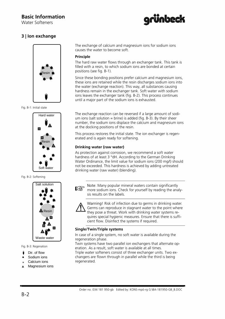
3 | Ion exchange
Resin
Fig. B-1: Initial state
The exchange of calcium and magnesium ions for sodium ions causes the water to become soft.
Principle The hard raw water flows through an exchanger tank. This tank is filled with a resin, to which sodium ions are bonded at certain positions (see fig. B-1).
Since these bonding positions prefer calcium and magnesium ions, these ions are retained while the resin discharges sodium ions into the water (exchange reaction). This way, all substances causing hardness remain in the exchanger tank. Soft water with sodium ions leaves the exchanger tank (fig. B-2). This process continues until a major part of the sodium ions is exhausted.
Resin
Hard water
Soft water
Fig. B-2: Softening
The exchange reaction can be reversed if a large amount of sodi-um ions (salt solution = brine) is added (fig. B-3). By their sheer number, the sodium ions displace the calcium and magnesium ions at the docking positions of the resin.
This process restores the initial state. The ion exchanger is regen-erated and is again ready for softening. Drinking water (raw water) As protection against corrosion, we recommend a soft water hardness of at least 3 °dH. According to the German Drinking Water Ordinance, the limit value for sodium ions (200 mg/l) should not be exceeded. This hardness is achieved by adding untreated drinking water (raw water) (blending).
Resin
Salt solution
Waste water
Fig. B-3: Regenation
Dir. of flow Sodium ions Calcium ions Magnesium ions
Note: Many popular mineral waters contain significantly more sodium ions. Check for yourself by reading the analy-sis results on the labels.
Warning! Risk of infection due to germs in drinking water. Germs can reproduce in stagnant water to the point where they pose a threat. Work with drinking water systems re-quires special hygienic measures. Ensure that there is suffi-cient flow. Disinfect the systems if required.
Single/Twin/Triple systems In case of a single system, no soft water is available during the regeneration phase. Twin systems have two parallel ion exchangers that alternate op-eration. As a result, soft water is available at all times. Triple water softeners consist of three exchanger units. Two ex-changers are flown through in parallel while the third is being regenerated.
Product Description
GENO-mat® WF
Order no. 054 182 941-gb Edited by: KONS-mpö-rg G:\BA-182941-GB-C.DOC
C-1
C Product Description (GENO-mat® WF)
Contents
1 Type Designation Plate ..................................................
2 Technical Specifications .................................................
3 Appropriate Application ................................................
4 Scope of Delivery .......................................................... 4.1 Basic Equipment ..................................................... 4.2 Optional Features .................................................... 4.3 Consumables .......................................................... 4.4 Wearing Parts .........................................................
C-1
C-1
C-4
C-4 C-4 C-5 C-6 C-7
1 Type Designation Plate
The type designation plate is located at the control valve of the softening system. When contacting Grünbeck regarding inquiries or orders, please specify the indicated information. Please copy the information indicated on the type designation plate to the table below, so that all required information is always available.
Softening System GENO-mat® WF
Type: Serial Number: /
Order Number: 2 Technical Specification
The softening system GENO-mat® WF is a single system with an integrated bypass for the supply of raw water during the regeneration. As soon as the pre-set water volume in one exchanger tank has been softened, the regeneration is released.
All system data are shown in table C-1 and C-2. The values indicated refer to standard softening systems. Different data for special versions are listed separately, if necessary.
Warning! During extended periods of standstill, germs may pollute the drinking water. The automatic regeneration counteracts this effect. Therefore, do not disconnect the system from power and water supply, if you are absent for longer periods of time.
Attention! Electrically operated valves. In case of power failure during the regeneration, water may flow into the drain or into the brine tank. In case of power failure, check the system and shut off the water supply, if necessary.

Product Description GENO-mat® WF
Order no. 054 182 941-gb Edited by: KONS-mpö-rg G:\BA-182941-GB-C.DOC
C-2
Technical Data/Specifications Water Softener GENO-mat® WF Systems with full salting 65 150 300 450 750 1000 1500 2400 Connection Data Nominal connection diameter DN 25 (1" male) DN 40 (1½"
female) DN 50 (2“ female)
Drain connection, min. DN 50 Power supply [V]/[Hz] 230/50-60
(system operation with protective low voltage 24/50-60) Electrical connected power [VA] 10 Protective system IP 54 Performance Data Nominal pressure (PN) [bar] 10 Operating pressure min/max. [bar] 2.0/8.0 Peak flow rate *** at residual hardness < 0.1 °DH
[m³/h] 2.0 3.0 5.0 6.0 9.5 13.5 17.5 24.0
Pressure loss at max. continuous flow rate [bar] 0.7 1.1 2.0 1.3 1.8 2.5 3.6 4.7
kV-value (at p = 1.0 bar) [m³/h] 2.7 2.8 3.3 4.9 6.4 7.7 8.0 10.9
Nominal capacity [mol][m³ x °DH]
12.067
26.6149
53.9302
80.2449
133.2746
177.9 996
268 1504
429.3 2404
Capacity per kg regeneration salt [mol/kg] 3.33 3.32 3.32 3.16 3.33 3.17 3.16 2.98
Time capacity [m³x°dH/h] 72 84 145 214 269 390 430 608 Regeneration time [min] 48.5 92.5 108.5 109.3 144.7 133.3 182.3 206.4 Dimensions and Weights total height [mm] 1340 1560 1830 1820 1940 1900 2140 2300 total height (without control electronics) **** [mm] 1070 1290 1560 — — — — —
Exchanger tank [mm] 208 257 334 369 469 552 618 770
Brine tank * [mm] 500 570 700 780 900 1000 1000 1200
Brine tank total height * [mm] 810 880 870 1100 1250 1330 1600 1560 Height of safety overflow, brine tank * [mm] 700 780 770 980 1120 1190 1460 1400 Connection height control valve (raw water) [mm] 940 1160 1430 1690 1810 1670 1920 2080 Foundation depth min. * [mm] 600 700 800 900 1000 1100 1100 1300 Foundation length min. * [mm] 1000 1100 1300 1500 1700 2000 2100 2400 Operating weight approx.* [kg] 255 375 610 930 1445 1865 2365 3480 Filling quantities and Consumption Data** Resin quantity [l] 18 40 81 115 200 255 385 600 Free board (resin in sodium form) approx. [mm] 270 230 290 390 300 210 190 240 Salt consumption per regeneration approx. [kg] 3.6 8.0 16.2 25.3 40.0 56.1 84.7 144.0 Regeneration salt storage max. * [kg] 130 190 285 485 760 1010 1260 1770 Total waste water quantity per reg. approx. [l] 112 211 451 693 1020 1428 2181 3803 Operating water volume [l] 10 22 45 70 111 156 235 400 Minimum salt filling height * [mm] — — — — 50 100 300 300 Ambient Data Water/ambient temperature max. [°C] 30/40 Control Data record in Code 290 2754 E 2755 E 2756 E 2866 E 2867 E 2908 E 2909 E 2400 E
* with standard brine tank ** Waste water volume and salt consumption refer to an inlet pressure of 3 bar. These values change at different inlet pressures and they shall only serve for approximate determination. *** The maximum/peak flow rates listed may decrease at high raw water hardness values. **** For systems with a nominal connection width of DN 40 and more, the fastening of the control electronics must be performed locally. Order no. 182 100 182 120 182 140 182 160 182 180 on
request on
request on
request
Product Description
GENO-mat® WF
Order no. 054 182 941-gb Edited by: KONS-mpö-rg G:\BA-182941-GB-C.DOC
C-3
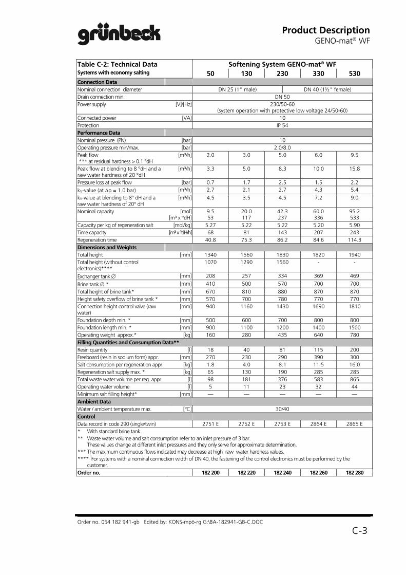
Table C-2: Technical Data Softening System GENO-mat® WF Systems with economy salting 50 130 230 330 530 Connection Data Nominal connection diameter DN 25 (1" male) DN 40 (1½" female) Drain connection min. DN 50 Power supply [V]/[Hz] 230/50-60
(system operation with protective low voltage 24/50-60) Connected power [VA] 10 Protection IP 54 Performance Data Nominal pressure (PN) [bar] 10 Operating pressure min/max. [bar] 2.0/8.0 Peak flow *** at residual hardness > 0.1 °dH
[m³/h] 2.0 3.0 5.0 6.0 9.5
Peak flow at blending to 8 °dH and a raw water hardness of 20 °dH
[m³/h] 3.3 5.0 8.3 10.0 15.8
Pressure loss at peak flow [bar] 0.7 1.7 2.5 1.5 2.2 kV-value (at p = 1.0 bar) [m³/h] 2.7 2.1 2.7 4.3 5.4 kV-value at blending to 8° dH and a raw water hardness of 20° dH
[m³/h] 4.5 3.5 4.5 7.2 9.0
Nominal capacity [mol][m³ x °dH]
9.5 53
20.0 117
42.3 237
60.0 336
95.2 533
Capacity per kg of regeneration salt [mol/kg] 5.27 5.22 5.22 5.20 5.90 Time capacity [m³ x °dH/h] 68 81 143 207 243 Regeneration time 40.8 75.3 86.2 84.6 114.3 Dimensions and Weights Total height [mm] 1340 1560 1830 1820 1940 Total height (without control electronics)****
1070 1290 1560 - -
Exchanger tank [mm] 208 257 334 369 469
Brine tank * [mm] 410 500 570 700 700 Total height of brine tank* [mm] 670 810 880 870 870 Height safety overflow of brine tank * [mm] 570 700 780 770 770 Connection height control valve (raw water)
[mm] 940 1160 1430 1690 1810
Foundation depth min. * [mm] 500 600 700 800 800 Foundation length min. * [mm] 900 1100 1200 1400 1500 Operating weight approx.* [kg] 160 280 435 640 780 Filling Quantities and Consumption Data** Resin quantity [l] 18 40 81 115 200 Freeboard (resin in sodium form) appr. [mm] 270 230 290 390 300 Salt consumption per regeneration appr. [kg] 1.8 4.0 8.1 11.5 16.0 Regeneration salt supply max. * [kg] 65 130 190 285 285 Total waste water volume per reg. appr. [l] 98 181 376 583 865 Operating water volume [l] 5 11 23 32 44 Minimum salt filling height* [mm] — — — — — Ambient Data Water / ambient temperature max. [°C] 30/40 Control Data record in code 290 (single/twin) 2751 E 2752 E 2753 E 2864 E 2865 E * With standard brine tank ** Waste water volume and salt consumption refer to an inlet pressure of 3 bar.
These values change at different inlet pressures and they only serve for approximate determination. *** The maximum continuous flows indicated may decrease at high raw water hardness values. **** For systems with a nominal connection width of DN 40, the fastening of the control electronics must be performed by the
customer. Order no. 182 200 182 220 182 240 182 260 182 280

Product Description GENO-mat® WF
Order no. 054 182 941-gb Edited by: KONS-mpö-rg G:\BA-182941-GB-C.DOC
C-4
3 Appropriate Application
Softening systems of the GENO-mat® WF series are designed for the softening and partial softening of cold drinking and service water. As single systems, they are suitable for applications where soft water is not permanently required. Systems for regeneration with full and economy salting are available. However, the type of regeneration is system-specific and must not be modified by the user.
Note: Only systems with full salting mode are suitable for softening to less than 0.1 °dH.
The water to be softened must be free of iron and manganese (less than 0.2 mg iron respectively 0.05 mg manganese per liter). A maximum water temperature of 30 °C must not be exceeded. The maximum ambient temperature is 40 °C.
The systems are suitable for the (partial) softening of well, process, boiler feed, cooling and air conditioning water.
The softening of drinking water must be performed according to the stipulations of the German Drinking Water Ordinance (residual hardness 3 °dH - 8 °dH, max. sodium concentration 200 mg/l (refer to chapter E, item 2.1)). This requires a blending valve which allows to add raw water
The system is adjusted to the soft water requirements to be expected at the installation site and is not suitable for performances differing considerably from these values. The peak flow must never be exceeded under any circumstances.
The system may only be operated if all components are installed properly and according to the regulations. Safety devices and mechanisms must NEVER be removed, tampered with, short-outed, bridged or otherwise rendered useless.
Appropriate application of the system also requires that the information given in this operating manual as well as the local safety guideline applying at the installation site be respected and the maintenance and inspection intervals be observed.
4 Scope of Delivery
4.1 Basic Equipment double-walled plastic exchanger tank
food compatible ion exchanger resin
Note: Smaller systems (up to GENO-mat® WF 300) come with the exchanger tank already filled with resin .
Control valve made of red bronze
PE brine tank incl. sieve bottom (separates salt supply chamber from brine chamber) and PP brine valve with safety float (controls the brine flow); with brine buffering technology.
Micro-processor controller with LCD (controls all system
Product Description
GENO-mat® WF
Order no. 054 182 941-gb Edited by: KONS-mpö-rg G:\BA-182941-GB-C.DOC
C-5
functions, indicates operating modes and errors)
Turbine water meter (TWZ) (may be replaced by a water meter with counter, see 4.2)
Water test kit “Total Hardness“ (see 4.3)
Operating manual
Only for systems with economy salting: disinfection unit
4.2 Optional Features
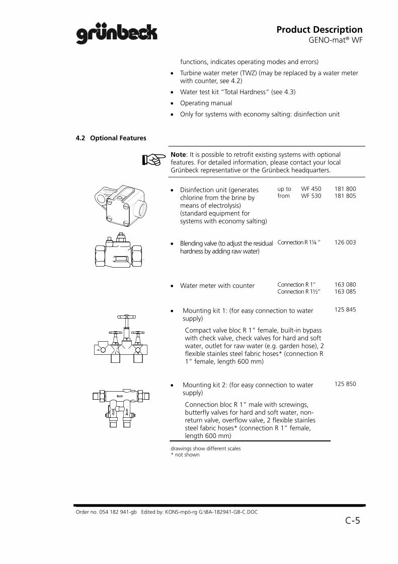
Note: It is possible to retrofit existing systems with optional features. For detailed information, please contact your local Grünbeck representative or the Grünbeck headquarters.
Disinfection unit (generates chlorine from the brine by means of electrolysis) (standard equipment for systems with economy salting)
up to WF 450 from WF 530
181 800 181 805
Blending valve (to adjust the residual hardness by adding raw water)
Connection R 1¼ ‘’
126 003
Water meter with counter Connection R 1’’ Connection R 1½’’
163 080 163 085
Mounting kit 1: (for easy connection to water supply)
Compact valve bloc R 1” female, built-in bypass with check valve, check valves for hard and soft water, outlet for raw water (e.g. garden hose), 2 flexible stainles steel fabric hoses* (connection R 1” female, length 600 mm)
125 845
Mounting kit 2: (for easy connection to water supply)
Connection bloc R 1” male with screwings, butterfly valves for hard and soft water, non-return valve, overflow valve, 2 flexible stainles steel fabric hoses* (connection R 1” female, length 600 mm)
drawings show different scales * not shown
125 850

Product Description GENO-mat® WF
Order no. 054 182 941-gb Edited by: KONS-mpö-rg G:\BA-182941-GB-C.DOC
C-6
Overflow valve, connection 1“ male, opening pressure 0.8 bar (to cover peak consumption by adding raw water, to be built into the bypass)
125 855
Recirculation unit with 2 flexible stainless steel fabric hoses (connection R 1’’ male, length 600 mm) (reduces the counter-ion effect during extended periods of standstill)
181 860
Volt.-free signal (indication of operating mode) 126 885
Automatic empty alarm for brine tank 181 880
Water stop for a reliable protection against water damages
Solenoid valve for installation into the piping, upstream of the water softener incl. sensor for leakage water, automatic switch-off and acoustic alarm signal.
Water stop R 1“.
Water stop R 1½“
126 855
126 860
Drawings show different scales
4.3 Consumables In order to ensure the reliable operation of the system, only use genuine consumables.
Regeneration salt (25 kg)
Water test kit “Total Hardness“
1 pc 10 pcs
127 001
170 145 170 100

Product Description
GENO-mat® WF
Order no. 054 182 941-gb Edited by: KONS-mpö-rg G:\BA-182941-GB-C.DOC
C-7
4.4 Wearing Parts
Seals and control piston are subject to wear and tear. Wearing parts are listed below.
Note: Although these are wearing parts, we are prepared to grant a limited warranty period of 6 months. The same applies for electrical components.
a) Seals, control piston, injector, actuator
Fig. C-1: Control valve Nominal connection width DN 25
Fig. C-2: Control valve Nominal connection width DN 40
Fig. C-3: Brine valve
b) Flat seals, nonreturn valve
Fig. C-4 Disinfection device (pre-assembled)
c) Disinfection device (only for systems with economy salting)
Product Description GENO-mat® WF
Order no. 054 182 941-gb Edited by: KONS-mpö-rg G:\BA-182941-GB-C.DOC
C-8
InstallationGENO-mat® WF
Order no. 054 182 942-gb Edited by: KONS-mpö-rg G:\BA-182942-GB-D.DOC
D-1
D Installation (GENO-mat® WF)
Contents
1 General Installation Instructions .................................... 1.1 Water Installation .................................................... 1.2 Electrical Installation ................................................
2 Preparations .................................................................. 2.1 Filling the Exchanger Tank ....................................... 2.2 Mounting of Brine Tube ..........................................
3 Connecting the System ................................................ 3.1 Water Connection .................................................. 3.2 Connection of Control Electronics ...........................
D - 1 D - 2 D - 3
D - 3 D - 3 D - 4
D - 5 D - 5 D - 7
1 General Installation Instructions
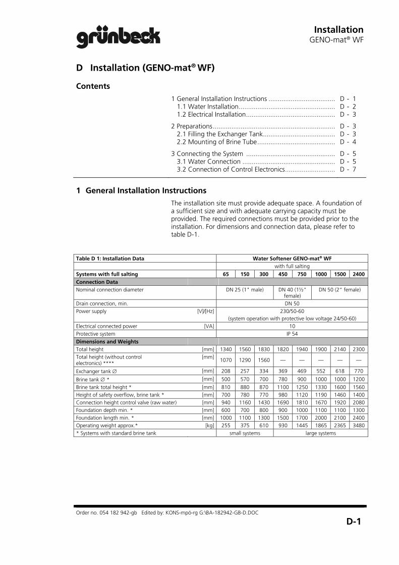
The installation site must provide adequate space. A foundation of a sufficient size and with adequate carrying capacity must be provided. The required connections must be provided prior to the installation. For dimensions and connection data, please refer to table D-1.
Table D 1: Installation Data Water Softener GENO-mat® WF with full salting
Systems with full salting 65 150 300 450 750 1000 1500 2400 Connection Data Nominal connection diameter DN 25 (1" male) DN 40 (1½"
female) DN 50 (2“ female)
Drain connection, min. DN 50 Power supply [V]/[Hz] 230/50-60
(system operation with protective low voltage 24/50-60) Electrical connected power [VA] 10 Protective system IP 54 Dimensions and Weights Total height [mm] 1340 1560 1830 1820 1940 1900 2140 2300 Total height (without control electronics) ****
[mm] 1070 1290 1560 — — — — —
Exchanger tank [mm] 208 257 334 369 469 552 618 770
Brine tank * [mm] 500 570 700 780 900 1000 1000 1200
Brine tank total height * [mm] 810 880 870 1100 1250 1330 1600 1560 Height of safety overflow, brine tank * [mm] 700 780 770 980 1120 1190 1460 1400 Connection height control valve (raw water) [mm] 940 1160 1430 1690 1810 1670 1920 2080 Foundation depth min. * [mm] 600 700 800 900 1000 1100 1100 1300 Foundation length min. * [mm] 1000 1100 1300 1500 1700 2000 2100 2400 Operating weight approx.* [kg] 255 375 610 930 1445 1865 2365 3480 * Systems with standard brine tank small systems large systems

Installation GENO-mat® WF
Order no. 054 182 942-gb Edited by: KONS-mpö-rg G:\BA-182942-GB-D.DOC
D-2
Table D 1: Installation Data Softening System GENO-mat® WF
with economy salting
50 130 230 330 530 Connection Data Nominal connection diameter DN 25
(1" male) DN 40
(1 1/2" female) Drain connection min. DN 50 Power supply [V]/[Hz] 230/50
(system operation with protective low voltage 24/50) Connected power [VA] 10 Protection IP 54 Dimensions and weights Total height [mm] 1070 1290 1560 1820 1940 Exchanger tank [mm] 208 257 334 369 469
Brine tank * [mm] 410 500 570 700 700 Total height brine tank * [mm] 670 810 880 870 870 Height safety overflow of brine tank * [mm] 570 700 780 770 770 Connection height control valve (raw water)
[mm] 940 1160 1430 1690 1810
Foundation depth min. * [mm] 500 600 700 800 800 Foundation length min. * [mm] 900 1100 1200 1400 1500 Operating weight approx.* [kg] 160 280 435 640 780 * Systems with standard brine tank small systems large systems
Note: Regarding systems with optional features (refer to chapter C, 4.2), also observe the operating instructions supplied with these features.
1.1 Water Installation While installing the softening system GENO-mat® WF, certain
rules and regulations must always be observed. Additional recommendations facilitate the operation of the system. The installation instructions described in this paragraph are illustrated in fig. D-1.
Binding Rules
The installation of a softening system represents a major interference with the drinking water installation and therefore may only be performed by an authorized expert.
Observe local installation guidelines and general regulations.
The system must be preceded by a fine filter (e.g. BOXER®).
Use corrosion-proof material for the soft water piping OR dose an anti-corrosion agent downstream of the system.
Provide a drain connection (minimum DN 50) to discharge the regeneration water.
Note: In case the regeneration water is removed by a sewage lifting system, this system must be salt water proof.
The system does not have a DVGW mark of conformity. According to DIN 1988, additional safety devices for the drinking water protection are required. Therefore:

InstallationGENO-mat® WF
Order no. 054 182 942-gb Edited by: KONS-mpö-rg G:\BA-182942-GB-D.DOC
D-3
Separate the softening system from the drinking water supply according to DIN 1988 Part 4 (e.g. by a Euro system separator GENO® DK-Standard).
Observe flow direction as far as indicated on pipes and hoses.
Recommendations
Provide a sampling valve directly downstream of the softening system. This makes the sampling for the regular hardness determinations (function control) easier.
1.2 Electrical Installation A shockproof socket is adequate for the electrical connection,
provided it adheres to the requirements indicated in table D-1, it is located at a distance of max. 1.20 m from the softening system and is constantly current-carrying (do not couple with light switch)!
2 Preparations
1. Unpack all system components.
2. Check for completeness and perfect condition.
3. Place both exchanger tanks at the appropriate location.
2.1 Filling the Exchanger Tank
The work described in the following only applies for large systems (GENO-mat® WF 450, GENO-mat® WF 750, GENO-mat® WF 330, GENO-mat® WF 530). Small systems come with the exchanger tanks already filled.
Table D-2 : Filling in the resin WF 330 / WF 450 WF 530 / WF 750
Resin quantity 115 l 200 l
WF 1000 WF 1500 WF 2400
Resin quantity 255 l 385 l 600 l
Center riser, fill in resin
1. Make sure that risers are closed with protective caps, plug on protective caps, if necessary. The protective caps prevent material from getting into the risers.
2. Center the risers in the exchanger tanks.
3. Fill the ion exchanger resin into the tanks, using the funnel supplied with the system.

Installation GENO-mat® WF
Order no. 054 182 942-gb Edited by: KONS-mpö-rg G:\BA-182942-GB-D.DOC
D-4
Remove protective cap, fasten control
valve
4. Fill the exchanger tanks with drinking water.
5. Exactly center the risers.
6. For the control valve connection, remove ion exchanger resin from threads and sealing surfaces of the exchanger tanks.
7. Remove protective caps from risers.
8. Fill exchanger tank with water.
9. Move the control valves with the nozzle from the top over the risers and fasten them by turning them clockwise.
2.2 Mounting of Brine Tube
Also refer to fig. D-1 (b), position 7.
1. Place the brine tank at the appropriate location.
2. Remove the brine tank cover.
Note: For easier mounting of the brine tube, the brine valve can be removed. To do so, remove the yellow cover and pull the brine valve out to the top.
Brine valve
Disinfection unit (pre-assembled)
3. Mount transition nipple (does not apply for WF 530, WF 750) and angle piece to brine valve.
4. Cut brine hose to the required length and plug on support sleeves on both ends.
5. Mount brine hose to brine valve
Only, if brine valve was removed: reinsert the brine valve and refit yellow cover.
Only for systems with disinfection unit:
6. Mount disinfection unit to the BVO-valve of the control valve (not required for small systems as they come pre-assembled).
8. Connect brine hose to disinfection unit.
For all other systems:
7. Connect brine hose to BVO-valve of control valve

InstallationGENO-mat® WF
Order no. 054 182 942-gb Edited by: KONS-mpö-rg G:\BA-182942-GB-D.DOC
D-5
3 Connecting the System
3.1 Water Connection 1. Connect the system to the water supply according to the installation drawing (fig. D-1 (a) and (b); pages D-6, D-7). Observe the instructions and recommendations given in chapter 1.
Note: The supplied water meter must be installed at the soft water side (after the system)
Attention! Dirt and corrosion particles may damage the system (control valve, ion exchanger resin). Flush supply pipe prior to start-up.
2. Connect the system to the drain by leading the drain hose to the drain and fastening it.
Attention! Damages and malfunctions may be caused by waste water which is not properly discharged. Therefore, do not bend hoses and do not route them higher than the device.
3. Route the hose of the brine tank overflow descending to the drain. Do not connect to drain hose!
Fig. D-1 (a) : Installation drawing for softening system GENO-mat® WF
Dimensions in fig. D-1 (a); excerpt from table D-1
Softening systems GENO-mat® WF 65 150 300 450 750 1000 1500 2400 (full salting) A Total height (without control electronics) ****
[mm] 1070 1290 1560 — — — — —
B Exchanger tank [mm] 208 257 334 369 469 552 618 770
C Brine tank * [mm] 500 570 700 780 900 1000 1000 1200
D Brine tank total height * [mm] 810 880 870 1100 1250 1330 1600 1560 E Height of safety overflow, brine tank * [mm] 700 780 770 980 1120 1190 1460 1400 F Connection height control valve (raw water)
[mm] 940 1160 1430 1690 1810 1670 1920 2080
* Systems with standard brine tank
Sampling valve Sampling valve

Installation GENO-mat® WF
Order no. 054 182 942-gb Edited by: KONS-mpö-rg G:\BA-182942-GB-D.DOC
D-6
Dimensions in fig. D-2 (a); excerpt from table D-1 Softening systems GENO-mat® WF 50 130 230 330 530 (economy salting) Total height [mm] 1070 1290 1560 1820 1940 Exchanger tank [mm] 208 257 334 369 469
Brine tank * [mm] 410 500 570 700 700 Total height brine tank * [mm] 670 810 880 870 870 Height safety overflow of brine tank * [mm] 570 700 780 770 770 Connection height control valve (raw water)
[mm] 940 1160 1430 1690 1810
* Systems with standard brine tank
Fine filter BOXER®
Euro system separator GENO® DK-2
Control electronics GENO®-IONO-matic
Water meter for soft water
Control valve
Exchanger tank
Brine tank
Brine tube
Drain connection
Raw water inlet 11 Soft water outlet
Fig. D-1 (b): Softening system GENO-mat®-WF, rear view
InstallationGENO-mat® WF
Order no. 054 182 942-gb Edited by: KONS-mpö-rg G:\BA-182942-GB-D.DOC
D-7
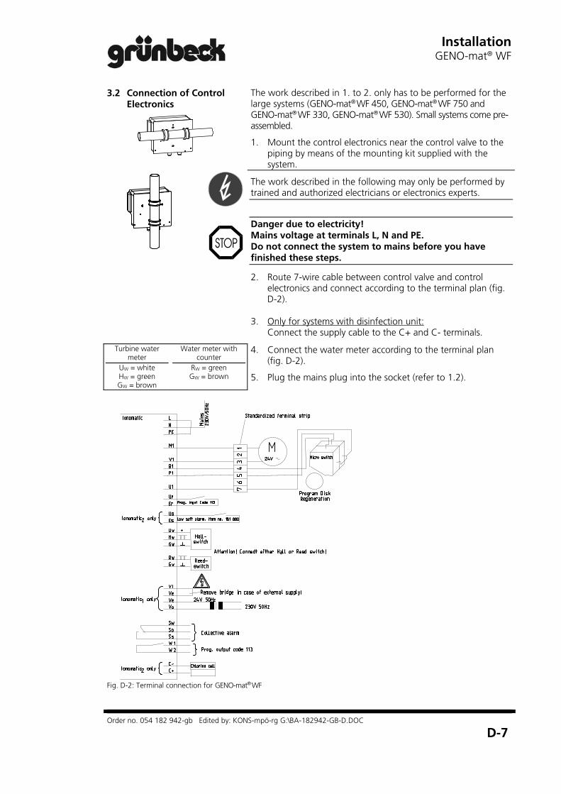
3.2 Connection of Control Electronics
The work described in 1. to 2. only has to be performed for the large systems (GENO-mat® WF 450, GENO-mat® WF 750 and GENO-mat® WF 330, GENO-mat® WF 530). Small systems come pre-assembled.
1. Mount the control electronics near the control valve to the piping by means of the mounting kit supplied with the system.
The work described in the following may only be performed by trained and authorized electricians or electronics experts.
Danger due to electricity! Mains voltage at terminals L, N and PE. Do not connect the system to mains before you have finished these steps.
2. Route 7-wire cable between control valve and control electronics and connect according to the terminal plan (fig. D-2).
3. Only for systems with disinfection unit: Connect the supply cable to the C+ and C- terminals.
Turbine water meter
UW = white HW = green GW = brown
Water meter with counter
RW = green GW = brown
4. Connect the water meter according to the terminal plan (fig. D-2).
5. Plug the mains plug into the socket (refer to 1.2).
Fig. D-2: Terminal connection for GENO-mat® WF

Installation GENO-mat® WF
Order no. 054 182 942-gb Edited by: KONS-mpö-rg G:\BA-182942-GB-D.DOC
D-8

Start-upGENO-mat® WF
Order no. 034 182 943-gb Edited by: KONS-mpö-rg G:\BA-182943-GB-E.DOC
E-1
E Start-up (GENO-mat® WF)
Contents
1 Filling the Brine Tank .....................................................
2 Setting the System ........................................................ 2.1 Setting the Blending Hardness ................................ 2.2 Setting the Controller .............................................
3 System Start-up .............................................................
E-1
E-2 E-2 E-3
E-5
The works described below may only be performed by trained and authorized experts. We recommend to have the start-up performed by Grünbeck’s Technical Service.
1 Filling the Brine Tank
1. Remove the brine tank cover.
2. Carefully fill in water until the water level is approx. 30 mm above the sieve bottom.
Attention! Impurities in the salt may cause malfunctions of the brine valve and the injector of the control valve. In order to ensure the proper functioning of the system, a defined salt quality is required.
Only use salt tablets that meet the requirements of DIN EN 973 A.
3. Fill salt tablets into the brine tank. Completely fill the brine tank.
4. Fill in the required operating water volume (table E-1).
5. Close the brine tank cover.
Table E-1: Filling the Brine Tank Softening system GENO-mat® WF Systems with full salting 65 150 300 450 750 1000 1500 2400 Regeneration salt supply max. * [kg] 130 190 285 485 760 1010 1260 1770 Operating water volume [l] 10 22 45 70 111 156 235 400
Systems with economy salting 50 130 230 330 530 Regeneration salt supply max. * [kg] 65 130 190 285 285 Operating water volume [l] 5 11 23 32 44 * for systems with standard brine tank

Start-up GENO-mat® WF
Order no. 034 182 943-gb Edited by: KONS-mpö-rg G:\BA-182943-GB-E.DOC
E-2
2 Setting the System
2.1 Setting the Blending Hardness
In case of systems with blending valve (optional feature), the blending hardness must be set. Open the valve at the raw water inlet. In order to set the blending hardness, also observe the operating instructions of the blending valve.
Note: When softening drinking water, you must observe the guidelines of the Drinking Water Act and any other applicable guidelines: Sodium concentration (max.): 200 mg/l. Regarding the blending hardness, please take into consideration item 3.1
Example
Softening of drinking water
Raw water (22 °dH) contains sodium (51.6 mg/l)
Possible sodium admixture during softening:
200 mg/l – 51.6 mg/l = 148.4 mg/l
Sodium concentration Please contact your water works for the sodium concentration in your raw water. When you soften the water by 1 °dH, the sodium concentration increases by approx. 8.2 mg/l. Therefore, if the pertinent Drinking Water Ordinance must be observed, you cannot soften the water to any degree desired. The permitted blending hardness results from the sodium concentration limit value and the raw water hardness.
200 mg/l (limit value acc. to Drinking Water Ordinance) – x mg/l (sodium concentration in the inlet water)
This determines the maximum permitted degree of softening:
y mg/l (possible sodium admixtures during softening)
dH188.2
148.4
This means: You must blend at least to 22 – 18 = 4 °dH!
y
8 2,= Z °dH (max. softening possible)
The raw water may only be softened by max. Z °dH. Depending on the sodium concentration of the inlet water, you must select a blending hardness that is below the permitted maximum value of 200 mg/l.
2.1.1 Recommended blending hardness
Blending hardness Result
3 – 5 °dH Very soft water – optimally suited for thermal devices – might cause problems in getting off soap
6 – 8 °dH Optimum soft water
Start-upGENO-mat® WF
Order no. 034 182 943-gb Edited by: KONS-mpö-rg G:\BA-182943-GB-E.DOC
E-3
2.2 Setting the Controller The softening system GENO-mat® WF features a volume control. The
operating parameters are already stored in the GENO®-IONO-matic controller. On start-up all parameters that are necessary for the automatic determination of the regeneration intervals must be entered. Furthermore, the factory-set values must be checked.
Note: For detailed information on the handling of the GENO®-IONO-matic controller, refer to chapter F.
1. Set the time. 2. Set the raw water hardness. 3. Set the blending hardness (water hardness at water meter).
Note: Regardless of the selected blending hardness, 0 °dH must be entered, if the water meter precedes the blending valve.
4. Check the factory-set data (operating parameters). Activate code 290 and adjust the displayed value according to table E-2.

Start-up GENO-mat® WF
Order no. 034 182 943-gb Edited by: KONS-mpö-rg G:\BA-182943-GB-E.DOC
E-4
Table E-2: Data in code 290 Softening System GENO-mat® WF Systems with full salting 65 150 300 450 750 1000 1500 2400 Data in code 290 (single/twin) 2754 E 2755 E 2756 E 2866 E 2867 E 2908 E 2909 E 2400 E
Systems with economy salting 50 130 230 330 530 Data in code 290 (single/twin) 2751 E 2752 E 2753 E 2864 E 2865 E
Note: Now the control electronics and control valves are automatically adjusted (synchronized). The electronics detects both exchangers as fully regenerated.
5. Check pre-setting of the “Water Meter Pulse“ (controller, code 290). The required setting depends on the water meter used. The display must show the respective value from table E-3 which corresponds to the water meter installed.
Table E-3: Intervals of water meter pulses (setting code 290)
Standard equipment of: Water Meter Pulse Interval Display small systems TWZ 1“ 0.029 l/Imp F 2
medium-sized and large systems TWZ 1 ½“, TWZ 2“ 0.075 l/Imp F 10 — with counter 100.0 l/Imp F 9
Start-upGENO-mat® WF
Order no. 034 182 943-gb Edited by: KONS-mpö-rg G:\BA-182943-GB-E.DOC
E-5
3 System Start-up
1. Open the valve at the raw water inlet.
2. Release a manual regeneration (refer to chapter F). One exchanger is regenerated.
3. Release a manual regeneration. Now the other exchanger is regenerated.
Note: All systems featuring low salt alarm have a pre-set delay period between 2 regenerations (factory-setting: 0.2 hours (= 12 minutes)). On completion of a regeneration, this delay period must pass before another manual regeneration can be released.
4. Open the valve at the soft water outlet when the regeneration is completed.
5. Perform a visual inspection. Make sure that no water leaks from the system and the system is tight.
6. Take a water sample at the sampling valve downstream of the system.
7. Perform a hardness determination with the water test kit “Total Hardness“. The system functions properly, if the water taken directly after the exchanger tank has a value of 0 °dH.
8. Fill in the cover sheet and checklist / column 1 of the operation log after performing the necessary measurings and testings.
Start-up GENO-mat® WF
Order no. 034 182 943-gb Edited by: KONS-mpö-rg G:\BA-182943-GB-E.DOC
E-6
OperationGENO®-IONO-matic
Order no. 034 182 944-gb Edited by: KONS-mpö-rg G:\BA-182944-GB-F.DOC
F-1
F Operation (GENO®-IONO-matic)
Content
1 Introduction ..................................................................
2 Controller operation...................................................... 2.1 Controls and display .............................................. 2.2 Setting operating parameters ................................. 2.3 Reading the operating status ................................. 2.4 Releasing manual regeneration ..............................
F-1
F-2 F-2 F-3 F-8 F-8
1 Introduction
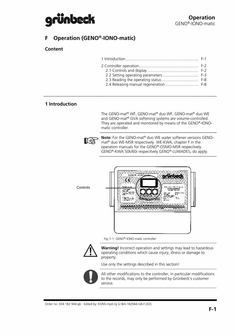
The GENO-mat® WF, GENO-mat® duo WF, GENO-mat® duo WE and GENO-mat® GVA softening systems are volume-controlled. They are operated and monitored by means of the GENO®-IONO-matic controller.
Note: For the GENO-mat® duo WE water softener versions GENO-mat® duo WE-MSR respectively. WE-KWA, chapter F in the operation manuals for the GENO®-OSMO-MSR respecitvely. GENO®-KWA 50k/60i respecitvely GENO®-LUWADES2 do apply.
Controls
Fig. F-1: GENO®-IONO-matic controller
Warning! Incorrect operation and settings may lead to hazardous operating conditions which cause injury, illness or damage to property.
Use only the settings described in this section!
All other modifications to the controller, in particular modifications to the records, may only be performed by Grünbeck's customer service.

Operation GENO®-IONO-matic
Order no. 034 182 944-gb Edited by: KONS-mpö-rg G:\BA-182944-GB-F.DOC
F-2
2 Controller operation
2.1 Controls and display
1 "Program" button in normal mode: switches to programming mode (hold
down for more than 5 seconds). in programming mode: opens menus. saves the setting and closes menus.
2 "Man. Reg." button in normal mode: releases manual regeneration
(hold down for more than 10 seconds).
in programming mode: switches to previous menu decrease the numerical values.
3 "Info" button in normal mode: activates the info mode and switches
to the next screen
8
6
7
9
5
4
31 2
Programm Hand Reg Info
Fig. F-2: GENO®-IONO-matic controller; operational controls and display
in programming mode: switches to the next menu increases the numerical values.
4 Display indicates the operating parameters
(see 5 - 10).
5 "Unit" indication indicates the unit of the numerical value (e.g.
°Gh, m3 ....).
6 "Regeneration" indication indicates the status of the regeneration of the
exchanger tank shown. Each arrow represents one step in the regeneration cycle. When the arrows form a circle, the regeneration is complete.
7 "Exchanger tanks" indication indicates the operating status of exchanger
tanks I and II (only twin systems). The active exchanger tank is shown on the left, the tank currently in regeneration or stand-by mode is shown on the right.
8 "Water Flow Pulse" indication indicates the water flow.
9 "Numerical values" indication indicates the time in normal mode. indicates the operating parameters in info
mode indicates the menu values in programming
mode. Open menus blink.

OperationGENO®-IONO-matic
Order no. 034 182 944-gb Edited by: KONS-mpö-rg G:\BA-182944-GB-F.DOC
F-3
2.2 Setting operating parameters
Principle
A programming mode must be activated before you can create settings (user programming mode: button 1, customer service programming mode: buttons 1 + 2).
In programming mode, button 3 switches to the next menu item, button 2 to the previous one. When you get to the parameter you want to change, press button 1 to open the menu. The display will blink. When the menu is open (blinking display), use buttons 2 and 3 to switch to lower or higher values. When the desired value is displayed (blinking), save it by pressing button 1. This closes the menu and the set value is displayed as a permanent value.
When all of the required settings have been saved, press buttons 2 and 3 simultaneously to exit the programming mode. The display returns to basic mode (time). The display also reverts to basic mode if no entries are made for more than 1 minute. Entries not saved by this time are lost.
Note: Instructions appearing in bold face are required so that work can proceed. All other steps can be skipped if the value displayed is not changed.
Basic settings (user programming mode)
The basic settings must be compatible with the conditions on site. The value must be changed accordingly in case of fluctuating raw water quality.
In basic mode, the operating status of the two exchanger tanks is displayed as well as the time saved in the system. First activate the user programming mode.
1. Hold down the "Program" button (1) for longer than 2.5 seconds.
The hour is displayed. If the display corresponds to the current time, skip steps 2 - 4.
2. Press the "Program" button (1). The displayed value begins to flash.
3. Set the correct time (hour). To do so: Press the "Man. Reg.“ button (2) to decrease the hour value OR Press the "Info“ button (4) to increase the hour value.
4. Save the setting by pressing button (1). The hour displayed will stop blinking.
5. Press the "Info" button (3) to switch to the next menu item.

Operation GENO®-IONO-matic
Order no. 034 182 944-gb Edited by: KONS-mpö-rg G:\BA-182944-GB-F.DOC
F-4
The minute value is displayed. If the value is correct, proceed with step 9.
6. Open the menu by pressing the "Program“ (1).
7. When the display starts to blink, use buttons (3) and (2) to increase or reduce the value.
8. As soon as the correct value id displayed, press button (1). The value will stop blinking.
9. Press the "Info" button (3) to switch to the next menu item.
The raw water hardness stored in the system is displayed. You must now enter the actual raw water hardness applying at your installation site. You can determine this value by means of the "Total hardness" water analysis kit or by inquiring at your local water works.
10. Enter the appropriate value. To do so, go through the steps described in 6 – 8.
11. Press the "Info" button (3) to switch to the next menu item.
The "blending hardness" menu item is displayed. Enter 0 °Gh if your system does not have a blending unit at all or if the blending unit is installed before the water meter. In all other cases, the blending hardness value must be set. The value is determined by the setting of the blending valve (between 0 °Gh and the raw water hardness). If drinking water is to be softened, the guidelines set out in the German Drinking Water Act must be complied with (refer to section E).
12. Enter the correct value. To do so, go through the steps described in 6 – 8.
13. Press the "Info" button (3) and the "Man. Reg." button (2) simultaneously to return to basic mode. The current time is displayed.

OperationGENO®-IONO-matic
Order no. 034 182 944-gb Edited by: KONS-mpö-rg G:\BA-182944-GB-F.DOC
F-5
Basic settings (customer service - programming mode)
All of the basic system parameters are saved in records. The system is ready for operation when the correct record has been selected. The factory-settings must be checked during start-up. In addition, the operating mode can be chosen.
Only Grünbeck customer service staff or authorized experts may modify settings in customer service programming mode.
Warning! Incorrect settings may lead to hazardous operating conditions which cause injury, illness or damage to property.
The guidelines in the instruction manual must be followed explicitly! Use only the settings described here!
Prerequisite: The system is in basic mode. The time is displayed.
1. Press the "Program" button (1) and the "Man. Reg." button(2) simultaneously until the display changes.
The customer service programming mode is active. First, select the required menu.
The numbers (000) blink. Modify the value so that the code for the required menu is displayed. The code for the required "System Setup" menu is 290.
2. Press the "Info" button (3) to increase the value until C. 290 is displayed. OR Press the "Man. Reg." button (2) to decrease the value until C. 290 is displayed. Hold down the buttons (2) or (3) to run through the numbers quickly. Fine tuning is possible by pressing and releasing the buttons.
3. Press the "Program" button (1) to confirm Code 290.
You can now choose the "language", i.e. the unit the system is to use for computing and displaying parameters. Choose between L 1: °dh, L 2: °fH and L 3: mol/l (mol is displayed). If no modifications are required, proceed with step.
4. Press the "Program" button (1) to open the menu. The display starts to blink.

Operation GENO®-IONO-matic
Order no. 034 182 944-gb Edited by: KONS-mpö-rg G:\BA-182944-GB-F.DOC
F-6
5. Set the required value by pressing the "Info“ button (3)
(loop L 1 L 2 L 3 L 1...). OR Set the required value by pressing the "Man. Reg.“ button (2). (loop L 1 L 3 L 2 L 1...).
6. Press button (1) to confirm the entry. The display stops blinking and the selected unit is displayed in the units field.
7. Press the "Info" button (3) to switch to the next parameter.
The number of the factory-preset record (standard operating parameters) is displayed. If the setting does not correspond to the record of your system (see section E), it must be modified.
8. Open the menu by pressing the "Program“ button (1). The display starts to blink.
9. Increase the displayed numerical value by means of the "Info“ button (3) OR Decrease the displayed numerical value by means of the "Man. Reg.“ (2) button. Hold down the buttons (2) or (3) to run through the numbers quickly. Fine tuning is possible by pressing and releasing the buttons (2) or (3).
10. When your system record blinks, press button (1) to confirm the setting.
11. Switch to the next menu item by pressing the "Info" button (3).
A 2 is displayed for a system with two exchanger tanks. The code for a system with one exchanger tank is A 1. The setting must be changed as required.
12. Open the menu by pressing button (1) (display blinks).
13. Press button (2) or button (3) to display the required value.
14. Confirm the new value by pressing button (1).
15. Switch to the next menu item by pressing the "Info“ button (3).
The nominal capacity stored in the record is displayed. This setting cannot be modified.
16. Switch to the next menu item by pressing the "Info" button (3).

OperationGENO®-IONO-matic
Order no. 034 182 944-gb Edited by: KONS-mpö-rg G:\BA-182944-GB-F.DOC
F-7
The parameter "Water Meter Pulse" is displayed. Table F-1 indicates what the codes represent.
The setting required depends on the water meter installed in your system (see section E).
17. Change the setting as required. Proceed as instructed in steps 8 - 10.
Table: F-1: Code 290 display values and corresponding water meter pulse intervals
F 00 F 01 F 02 F 03 F 04 F 05 F 06 F 07 F 08 F 09 F 10
l / pul. variable 0.012 0.029 0.33 0.5 0.93 1.33 3.8 5.3 100.0 0.075
18. Switch to the next menu item by pressing the "Info"
button (3).
The water meter pulse just set is displayed (l/pulse).
19. Switch to the next menu item by pressing the "Info" button (3).
The "Operating Mode“ is displayed. The standard setting is mode 3 (b 3 is displayed): Regeneration as soon as the specified volume of soft water has been reached, or at the latest after a preset number (1 - 99) of days. Factory-setting for GENO-mat® duo WE 50, 130, 230: Regeneration after 4 days at the latest, at 03:00 am at night. (based on DIN 19636). Factory-setting for all other systems: Regeneration after 4 days at the latest, at 03:00 am at night. The factory-setting can be modified by Grünbeck’s customer service/authorised service company and be adapted to the requirements on site.
Other operating modes:
b 1: Time-dependent control. Regeneration after 1 - 99 days.
b 2: Volume-dependent control. Regeneration as soon as the total capacity is reached. No timer priority control.
b 4, b 5, b 6: Special modes (contact customer service for more details).
20. Press button (1) to select another operating mode. The display blinks.
21. Set the required operating mode (b1 , b2 or b 3) by means of buttons (2) or (3).
22. Save the setting by pressing button (1).
23. Press buttons (2) and (3) simultaneously to return to the basic mode. The time is displayed, the system is ready for operation.
Operation GENO®-IONO-matic
Order no. 034 182 944-gb Edited by: KONS-mpö-rg G:\BA-182944-GB-F.DOC
F-8
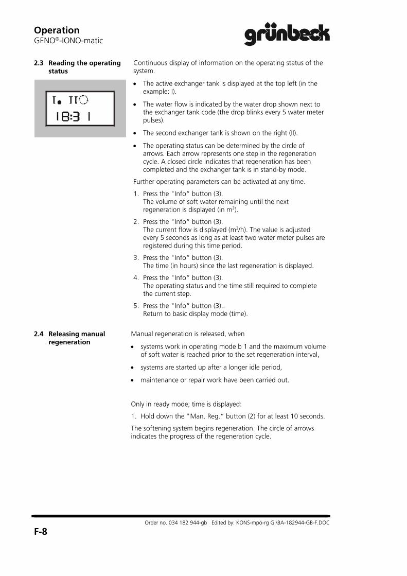
2.3 Reading the operating status
Continuous display of information on the operating status of the system.
The active exchanger tank is displayed at the top left (in the example: I).
The water flow is indicated by the water drop shown next to the exchanger tank code (the drop blinks every 5 water meter pulses).
The second exchanger tank is shown on the right (II).
The operating status can be determined by the circle of arrows. Each arrow represents one step in the regeneration cycle. A closed circle indicates that regeneration has been completed and the exchanger tank is in stand-by mode.
Further operating parameters can be activated at any time.
1. Press the "Info“ button (3). The volume of soft water remaining until the next regeneration is displayed (in m3).
2. Press the "Info“ button (3). The current flow is displayed (m3/h). The value is adjusted every 5 seconds as long as at least two water meter pulses are registered during this time period.
3. Press the "Info“ button (3). The time (in hours) since the last regeneration is displayed.
4. Press the "Info“ button (3). The operating status and the time still required to complete the current step.
5. Press the "Info“ button (3).. Return to basic display mode (time).
2.4 Releasing manual
regeneration Manual regeneration is released, when
systems work in operating mode b 1 and the maximum volume of soft water is reached prior to the set regeneration interval,
systems are started up after a longer idle period,
maintenance or repair work have been carried out.
Only in ready mode; time is displayed:
1. Hold down the "Man. Reg.“ button (2) for at least 10 seconds.
The softening system begins regeneration. The circle of arrows indicates the progress of the regeneration cycle.

TroubleshootingGENO-mat® WF / GENO-mat® duo WE
Order no. 034 182 946-gb Edited by: KONS-mpö-rg G:\BA-182946-GB-G.DOC
G-1
G Troubleshooting (GENO-mat® WF / GENO-mat® duo WE)
Even carefully designed and manufactured technical systems that
are operated properly, may experience malfunctions. Table G-1 provides an overview of possible problems that may occur during the operation of the softening systems GENO-mat® WF and GENO-mat® duo WE and indicates the causes and their elimination.
The softening systems GENO-mat® WF and GENO-mat® duo WE are equipped with error detection and reporting system. If an error message is displayed:
1. Press the “Program“ key (= confirm the malfunction).
2. Watch the display. If the message reappears, compare it with table G-1.
3. If necessary, call technical service.
Note: For the water softener versions GENO-mat® duo WE-MSR respectively WE-KWA, the error detection and reporting system described in the chapter G of the respective operation manuals GENO®-OSMO-MSR or GENO®-KWA 50k/60i and GENO®-LUWADES2 does apply.
Note: The technical service definitely must be notified in case of malfunctions that cannot be remedied with the information given in table G-1! When contacting the technical service, please provide the system designation, serial number and the error message displayed.
Table G-1 : Troubleshooting
What you see Why it happened What to do
a) Error messages displayed Er 1 Step time monitoring regeneration
motor. Defective motor connection cables or switch
Notify Grünbeck’s technical service
Er 2 Step time monitoring transfer motor. Defective motor connection cables or switch
Notify Grünbeck’s technical service
Er 4 Low salt alarm Check salt level in brine tank and add salt tablets according to DIN 19 604
What you see Why it happened What to do
b) "Service" message displayed SEr Maintenance is due (message is
displayed after 1 year at the latest). For information purposes only. This is not a malfunction.
Press the "Program“ button (= confirm). Message is displayed again after one hour. Reset by Grünbeck's technical service after maintenance is completed.

Troubleshooting GENO-mat® WF / GENO-mat® duo WE
Order no. 034 182 946-gb Edited by: KONS-mpö-rg G:\BA-182946-GB-G.DOC
G-2
Table G-1 (continued)
What you see Why it happened What to do
c) Miscellaneous errors Increased hardness in the blending or soft water
System overrun, system runs beyond performance parameters
System has no permanent power (coupled with light switch)
Check power supply and adjust, if necessary
No water meter pulses in control electronics
Check water meter and control line and replace any faulty parts.
Incorrect electronic setting Check parameters in the electronics component and reset, if necessary.
System does not suck in brine
Clean injector, check inlet pressure and adjust, if necessary.
No salt in brine tank Not enough water in brine tank
Add salt Check BVO valve and brine valve for pollution and clean, if necessary.
Miscellaneous causes
Setting at the blending valve Check inlet resp. blending hardness. Check setting of blending valve and reset, if necessary.
Water supply interrupted Shut-off valves closed
Water volume too high (exceeds peak flow indicated on type designation plate)
Reduce water volume
not enough salt in brine tank Check salt level according to the mark and add salt, if necessary.
Resin in the outlet tube Defective jet system Notify Grünbeck’s technical service Pressure loss is too high Exchanger resin is polluted with
undissolved particles Notify Grünbeck’s technical service
Second exchanger regenerates and is in the “backwash“ step
Wait until regeneration is completed and check pressure loss again
System does not take in brine Water pressure is too low Increase flow pressure to at least 2.0 bar
Injector is clogged Clean injector
Injector sieve is clogged Clean injector sieve
Brine valve is clogged Remove brine valve and carefully clean it
Control valve continuously regenerates Switch is incorrectly adjusted, defective or short-circuited
Notify Grünbeck’s technical service
MaintenanceWater softeners
Order no. 084 181 945-gb Edited by: KONS-mpö-rg G:\BA-181945-GB-H.DOC
H-1
H Maintenance and care (water softeners)
Content
1 | General information ....................................................
2 | Inspection (functional check) ....................................... 2.1 How to refill salt ....................................................
3 | Maintenance ............................................................... 3.1 Operation log ........................................................
4 | Spare parts ..................................................................
H-1
H-1 H-2
H-3 H-4
H-4
1 | General information
In order to guarantee the reliable function of water softeners over a long period of time, some maintenance work has to be per-formed at regular intervals. This applies in particular to the soften-ing of drinking water where the required measures are defined in the pertinent regulations and guidelines. All regulations and guide-lines which apply at the installation site must be strictly adhered to.
DIN 1988 part 8 / A 12 stipulates:
An inspection must be performed at least every two months.
Maintenance must be carried out twice a year. However, annual maintenance is sufficient for water softeners that carry the DVGW-mark of conformity!
Maintenance must be performed by the Grünbeck’s technical ser-vice/authorised service company or by a specialised company.
An operation log must be kept in order to record the maintenance work performed.
Notes: A maintenance contract ensures that all the required maintenance work will be performed in due time.
The operation log is attached to this operation manual.
2 | Inspection (functional check)
You may perform the regular inspections yourself. We recommend inspecting the water softener at shorter intervals after installation, before switching over to the standard inspection cycle. However, an inspection is compulsory at least every two months.
Please refer to the following summary for the tasks to be per-formed within the framework of an inspection.

Maintenance Water softeners
Order no. 084 181 945-gb Edited by: KONS-mpö-rg G:\BA-181945-GB-H.DOC
H-2
Summary: Inspection work
Determine the raw water hardness. (water test kit „total hardness“)
Determine the soft water hardness (0 °Gh) or the blending water hardness for water softeners with blending valve (water test kit „total hardness“).
Check the controller settings: a) time b) raw water hardness (not ZF) c) soft water hardness (not ZF, WINNI-mat® VGX and Weichwassermeister 2 GSX)
Check the salt level in the brine tank. Refill salt, if necessary (see 2.1)
Attention! If the salt level falls below the minimum filling level, hardness may break through. Observe the minimum salt filling level (see Technical Specifications, chapter C). In case of systems where no specific value is indicated, refill the water softener as soon as the level has fallen to just a few centimetres.
Evaluate the salt consumption with reference to the water volume consumed.
Note: Minor deviations are normal and cannot be prevented tech-nically. If you detect major deviations, please contact Grünbeck’s technical service/authorised service company.
Check control valve to drain for tightness (in operating mode).
2.1 How to refill salt
Warning! Impurities in the salt tank may adversely affect the wa-ter quality.
For hygienic reasons be very careful when refilling salt.
Attention! Insoluble impurities in the salt may cause malfunctions at the brine valve and at the injector of the control valve. A de-fined salt quality is required for the reliable function of the water softener.
Only use salt tablets as per DIN EN 973 type A.

MaintenanceWater softeners
Order no. 084 181 945-gb Edited by: KONS-mpö-rg G:\BA-181945-GB-H.DOC
H-3
A few precautionary measures ensure hygienically and technically perfect conditions:
Only store the salt in dry and clean areas.
Do not use salt from packages that are already open.
Clean the outside of the packages before opening them.
Fill the regeneration salt directly from the package into the brine tank.
Close the brine tank immediately after filling. 3 | Wartung
According to DIN 1988 part 8 / A 12, maintenance work at water softeners may only be performed by Grünbeck’s technical ser-vice/authorised service company or a specialised company.
An operation log must be kept for water softeners. In this opera-tion log, the service technician records all maintenance and repair work performed. In case of an operational disturbance this log helps to identify possible sources of error. In addition the log doc-uments the proper system maintenance.
Make sure that all maintenance work is recorded in the opera-tion log.
Summary: Maintenance work
Read the water pressure, flow pressure and water meter value.
Determine the hardness: raw water hardness, soft water hardness, 0 °Gh test
Re-adjust the blending valve and check the blending hardness again, if necessary. In case of Delta-p, program the desired soft water hardness in the control unit.
Adjust the electronics settings with reference to the measured hardness values (not ZF).
Check the programming of the control unit (not ZF).
Check the brine regulation (salting, filling of salt tank) and pro-gram settings; re-adjust them, if necessary.
Check release of regeneration.
Check start of turbine water meters (not ZF).
Check control valve for tightness, replace wearing seals if neces-sary, check the function of the drive motor of the control valve, clean injector and sieve.
For Weichwassermeister 2 GSX, WINNI-mat® VGX and Delta-p: Lubricate the pair of regeneration disks with grease; lubricate the pair of transfer disks with grease (only GSX).
Clean brine tank and brine valve.

Maintenance Water softeners
Order no. 084 181 945-gb Edited by: KONS-mpö-rg G:\BA-181945-GB-H.DOC
H-4
Check regeneration salt supply (quantity and quality).
Check hose connections and seals for tightness and replace them, if necessary.
Attention: Danger of water damage! Damaged or worn hose connections may tear. Therefore, DIN 1988, part 8, paragraph A 12 recommends replac-ing the flexible connection hoses after two years.
Observe continuation on page H-4!
Check the non-return function of the safety fitting (e.g. system
separator). Not required for intrinsically safe water softeners, in particular wa-ter softeners with DVGW-mark of conformity!
For water softeners with disinfection unit: functional check of the disinfection unit (determine electric current). - In case of Delta-p only possible via Code.
If necessary, read regeneration counter, total soft water volume, error memory (not ZF). - In case of Delta-p, system data print possible via serial interface.
If necessary, re-set service interval (not ZF).
Record all data and activities, including repair work in the opera-tion log.
Hand over the water softener and the filled out operation log to the operator.
3.1 Operation log The operation log is attached to this operation manual. At start-up
of the water softener, make sure to enter all data on the cover sheet of the operation log and to fill in the first column of the check list.
The service technician will fill in another column of the check list whenever further maintenance is carried out. This document pro-vides evidence of proper maintenance.
4 | Spare parts For spare parts and consumables, please contact your local
Grünbeck representative (refer to enclosed list).
Note: Also observe the general warranty terms indicated in chap-ter A-2. For detailed specifications regarding the wearing parts, please refer to chapter C.

Order no. 014 182 947-gb Edited by: KONS/mpö g:\ BA-182947-GB-BHB.DOC
Operation Log Customer
Name: ........................................................................
Address: .....................................................................
..................................................................................
..................................................................................
Softening system GENO-mat® WF
(please check appropriate box)
Serial number .............................................................
Installed by .................................................................
Filter: manufacturer/type ............... / ...........................
50130230330530
65150300450750
100015002400
Connection data: Drain connection DIN 1988 yes no
(please check appropriate box) Bottom outlet available yes no
Pipe leading to softening system
galvanized
copper
plastic
G r ü n b e c k W a s s e r a u f b e r e i t u n g G m b H
Industriestrasse 1 89420 Hoechstaedt/Germany P.O. Box 11 40 89416 Hoechstaedt/Germany Phone +49 9074 41-0 Fax +49 9074 41-100 [email protected] www.gruenbeck.de


Operation LogGENO-mat® WF
Order no. 014 182 947-gb Edited by: KONS-mpö-rg G:\BA-182947-GB-BHB.DOC
1
Maintenance of softening system GENO-mat® WF
Check list Please enter measured values. Confirm checks with OK or enter repair work performed.
Maintenance performed (date) start-up
Measured values
Water pressure [bar]
Flow pressure [bar]
Water meter value [m³]
Inlet hardness °Gh (measured)
Blending hardness °Gh(measured)
0 °Gh check
Inspections and checks of controller and control valve
Controller settings checked
Regeneration release checked
Injector and sieve cleaned
Control valve checked for tightness
Driving motor function checked
Brine tank and brine valve
Brine tank and brine valve cleaned
Brine valve functions and settings checked
Connections, hose connections, seals
Seals and hose connections checked
Safety fitting (e.g. system separator) checked for non-return function
Miscellaneous
Remarks
TS technician
Company
Work time cert (no.)
Signature

Operation Log GENO-mat® WF
Order no. 014 182 947-gb Edited by: KONS-mpö-rg G:\BA-182947-GB-BHB.DOC
2
Maintenance of softening system GENO-mat® WF
Check list Please enter measured values. Confirm checks with OK or enter repair work performed.
Maintenance performed (date)
Measured values
Water pressure [bar]
Flow pressure [bar]
Water meter value [m³]
Inlet hardness °Gh (measured)
Blending hardness °Gh(measured)
0 °Gh check
Inspections and checks of controller and control valve
Controller settings checked
Regeneration release checked
Injector and sieve cleaned
Control valve checked for tightness
Driving motor function checked
Brine tank and brine valve
Brine tank and brine valve cleaned
Brine valve functions and settings checked
Connections, hose connections, seals
Seals and hose connections checked
Safety fitting (e.g. system separator) checked for non-return function
Miscellaneous
Remarks
TS technician
Company
Work time cert (no.)
Signature
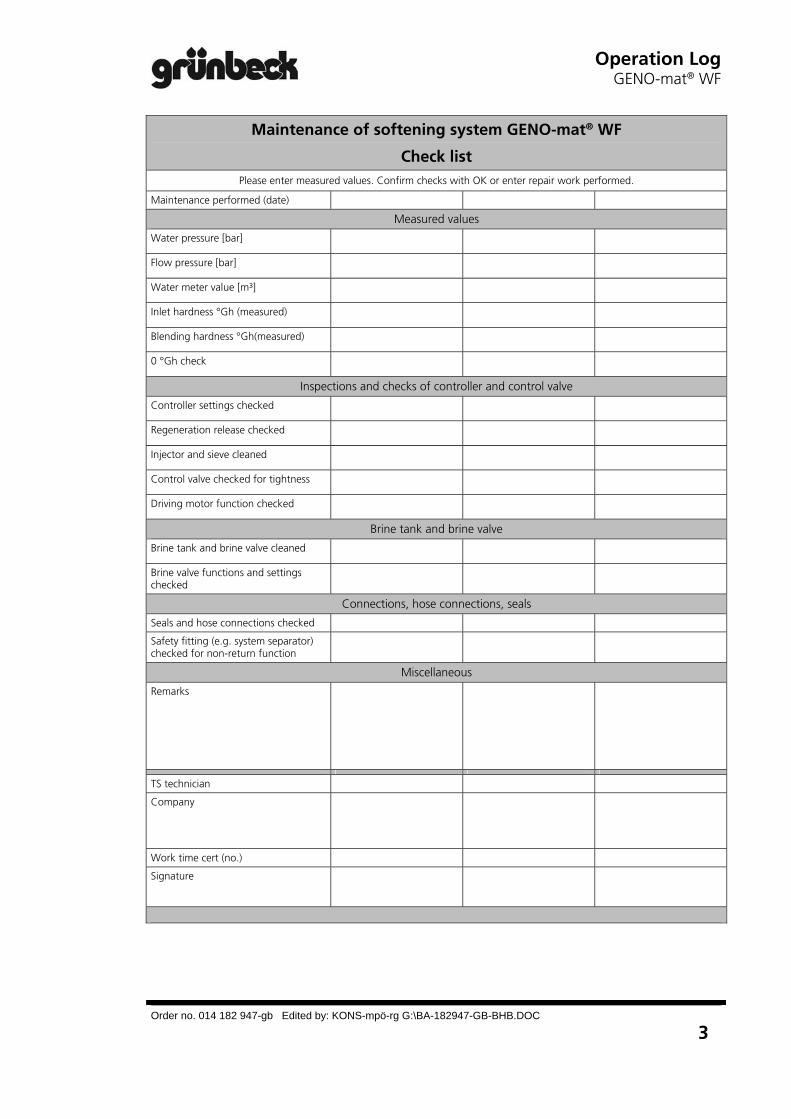
Operation LogGENO-mat® WF
Order no. 014 182 947-gb Edited by: KONS-mpö-rg G:\BA-182947-GB-BHB.DOC
3
Maintenance of softening system GENO-mat® WF
Check list Please enter measured values. Confirm checks with OK or enter repair work performed.
Maintenance performed (date)
Measured values
Water pressure [bar]
Flow pressure [bar]
Water meter value [m³]
Inlet hardness °Gh (measured)
Blending hardness °Gh(measured)
0 °Gh check
Inspections and checks of controller and control valve
Controller settings checked
Regeneration release checked
Injector and sieve cleaned
Control valve checked for tightness
Driving motor function checked
Brine tank and brine valve
Brine tank and brine valve cleaned
Brine valve functions and settings checked
Connections, hose connections, seals
Seals and hose connections checked
Safety fitting (e.g. system separator) checked for non-return function
Miscellaneous
Remarks
TS technician
Company
Work time cert (no.)
Signature
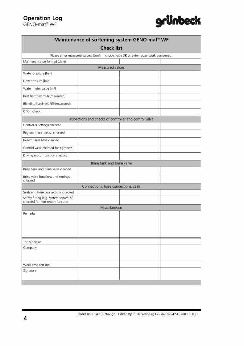
Operation Log GENO-mat® WF
Order no. 014 182 947-gb Edited by: KONS-mpö-rg G:\BA-182947-GB-BHB.DOC
4
Maintenance of softening system GENO-mat® WF
Check list Please enter measured values. Confirm checks with OK or enter repair work performed.
Maintenance performed (date)
Measured values
Water pressure [bar]
Flow pressure [bar]
Water meter value [m³]
Inlet hardness °Gh (measured)
Blending hardness °Gh(measured)
0 °Gh check
Inspections and checks of controller and control valve
Controller settings checked
Regeneration release checked
Injector and sieve cleaned
Control valve checked for tightness
Driving motor function checked
Brine tank and brine valve
Brine tank and brine valve cleaned
Brine valve functions and settings checked
Connections, hose connections, seals
Seals and hose connections checked
Safety fitting (e.g. system separator) checked for non-return function
Miscellaneous
Remarks
TS technician
Company
Work time cert (no.)
Signature

Operation LogGENO-mat® WF
Order no. 014 182 947-gb Edited by: KONS-mpö-rg G:\BA-182947-GB-BHB.DOC
5
Maintenance of softening system GENO-mat® WF
Check list Please enter measured values. Confirm checks with OK or enter repair work performed.
Maintenance performed (date)
Measured values
Water pressure [bar]
Flow pressure [bar]
Water meter value [m³]
Inlet hardness °Gh (measured)
Blending hardness °Gh(measured)
0 °Gh check
Inspections and checks of controller and control valve
Controller settings checked
Regeneration release checked
Injector and sieve cleaned
Control valve checked for tightness
Driving motor function checked
Brine tank and brine valve
Brine tank and brine valve cleaned
Brine valve functions and settings checked
Connections, hose connections, seals
Seals and hose connections checked
Safety fitting (e.g. system separator) checked for non-return function
Miscellaneous
Remarks
TS technician
Company
Work time cert (no.)
Signature

Operation Log GENO-mat® WF
Order no. 014 182 947-gb Edited by: KONS-mpö-rg G:\BA-182947-GB-BHB.DOC
6
Maintenance of softening system GENO-mat® WF
Check list Please enter measured values. Confirm checks with OK or enter repair work performed.
Maintenance performed (date)
Measured values
Water pressure [bar]
Flow pressure [bar]
Water meter value [m³]
Inlet hardness °Gh (measured)
Blending hardness °Gh(measured)
0 °Gh check
Inspections and checks of controller and control valve
Controller settings checked
Regeneration release checked
Injector and sieve cleaned
Control valve checked for tightness
Driving motor function checked
Brine tank and brine valve
Brine tank and brine valve cleaned
Brine valve functions and settings checked
Connections, hose connections, seals
Seals and hose connections checked
Safety fitting (e.g. system separator) checked for non-return function
Miscellaneous
Remarks
TS technician
Company
Work time cert (no.)
Signature