operation manual - x-rite · 2017-02-09 · color i7 operation manual 1 ce declaration hereby,...
TRANSCRIPT

Color i7 Benchtop Spectrophotometer
Operation Manual


C O L O R I 7 O P E R A T I O N M A N U A L
1
CE Declaration Hereby, X-Rite, Incorporated, declares that this Color i5, or Color i7 is in compliance with the essential requirements and other relevant provisions of Directive(s) EMC 2004/108/EC, LVD 2006/95/EC, and RoHS 2011/65/EU (Category 9, industrial).
Federal Communications Commission Notice NOTE: This equipment has been tested and found to comply with the limits for a Class A digital device, pursuant to Part 15 of the FCC Rules. These limits are designed to provide reasonable protection against harmful interference when the equipment is operated in a commercial environment. This equipment generates, uses, and can radiate radio frequency energy and, if not installed and used in accordance with the instruction manual, may cause harmful interference to radio communications. Operation of this equipment in a residential area is likely to cause harmful interference in which case the user will be required to correct the interference at his own expense.
Industry Canada Compliance Statement CAN ICES-3 (A) / NMB-3 (A)
Equipment Information Use of this equipment in a manner other than that specified by X-Rite, Incorporated may compromise design integrity and become unsafe. WARNING: This instrument is not for use in explosive environments. CAUTION: Do not stare into operating lamp. IR emitted from this product. Instructions for disposal: Please dispose of Waste Electrical and Electronic Equipment (WEEE) at designated collection points for the recycling of such equipment.
Proprietary Notice The information contained in this manual is derived from patent and proprietary data of X-Rite, Incorporated. The contents of this manual are the property of X-Rite, Incorporated and are copyrighted. Any reproduction in whole or part is strictly prohibited. Publication of this information does not imply any rights to reproduce or use this manual for any purpose other than installing, operating, or maintaining this instrument. No part of this manual may be reproduced, transcribed, transmitted, stored in a retrieval system, or translated into any language or computer language, in any form or by any means, electronic, magnetic, mechanical, optical, manual, or otherwise, without the prior written permission of an officer of X-Rite, Incorporated.
This product may be covered by one or more patents. Refer to the instrument for actual patent numbers.
Copyright © 2013 by X-Rite, Incorporated “ALL RIGHTS RESERVED” X-Rite® is a registered trademark of X-Rite, Incorporated. All other logos, brand names, and product names mentioned are the properties of their respective holders.

C O L O R I 7 O P E R A T I O N M A N U A L
2
Warranty Information X-Rite warrants this Product against defects in material and workmanship for a period of twelve (12) months from the date of shipment from X-Rite’s facility, unless mandatory law provides for longer periods. During such time, X-Rite will either replace or repair at its discretion defective parts free of charge. X-Rite’s warranties herein do not cover failure of warranted goods resulting from: (i) damage after shipment, accident, abuse, misuse, neglect, alteration or any other use not in accordance with X-Rite’s recommendations, accompanying documentation, published specifications, and standard industry practice; (ii) using the device in an operating environment outside the recommended specifications or failure to follow the maintenance procedures in X-Rite’s accompanying documentation or published specifications; (iii) repair or service by anyone other than X-Rite or its authorized representatives; (iv) the failure of the warranted goods caused by use of any parts or consumables not manufactured, distributed, or approved by X-Rite; (v) any attachments or modifications to the warranted goods that are not manufactured, distributed or approved by X-Rite. Consumable parts and Product cleaning are also not covered by the warranty. X-Rite‘s sole and exclusive obligation for breach of the above warranties shall be the repair or replacement of any part, without charge, which within the warranty period is proven to X-Rite‘s reasonable satisfaction to have been defective. Repairs or replacement by X-Rite shall not revive an otherwise expired warranty, nor shall the same extend the duration of a warranty. Customer shall be responsible for packaging and shipping the defective product to the service center designated by X-Rite. X-Rite shall pay for the return of the product to Customer if the shipment is to a location within the region in which the X-Rite service center is located. Customer shall be responsible for paying all shipping charges, duties, taxes, and any other charges for products returned to any other locations. Proof of purchase in the form of a bill of sale or receipted invoice which is evidence that the unit is within the Warranty period must be presented to obtain warranty service. Do not try to dismantle the Product. Unauthorized dismantling of the equipment will void all warranty claims. Contact the X-Rite Support or the nearest X-Rite Service Center, if you believe that the unit does not work anymore or does not work correctly. THESE WARRANTIES ARE GIVEN SOLELY TO BUYER AND ARE IN LIEU OF ALL OTHER WARRANTIES, EXPRESSED OR IMPLIED, INCLUDING BUT NOT LIMITED TO THE IMPLIED WARRANTIES OF MERCHANTABILITY, FITNESS FOR A PARTICULAR PURPOSE OR APPLICATION, AND NON-INFRINGEMENT. NO EMPLOYEE OR AGENT OF X-RITE, OTHER THAN AN OFFICER OF X-RITE, IS AUTHORIZED TO MAKE ANY WARRANTY IN ADDITION TO THE FOREGOING. IN NO EVENT WILL X-RITE BE LIABLE FOR ANY OF BUYER’S MANUFACTURING COSTS, OVERHEAD, LOST PROFITS, GOODWILL, OTHER EXPENSES OR ANY INDIRECT, SPECIAL, INCIDENTAL OR CONSEQUENTIAL DAMAGES BASED UPON BREACH OF ANY WARRANTY, BREACH OF CONTRACT, NEGLIGENCE, STRICT TORT, OR ANY OTHER LEGAL THEORY. IN ANY EVENT OF LIABILITY, X-RITE’S MAXIMUM LIABILITY HEREUNDER WILL NOT EXCEED THE PRICE OF THE GOODS OR SERVICES FURNISHED BY X-RITE GIVING RISE TO THE CLAIM.

C O L O R I 7 O P E R A T I O N M A N U A L
3
Table of Contents Before using your spectrophotometer… 4 Safety first! 4 Performance and Environmental Specifications 5 What’s in the box? 6
Optional Accessories 6 Spectrophotometer Setup 7 Sample Preview Methods 7 Sample Door 8 Computer Monitor Used for Sample Preview 9 Optional LCD Sample Preview Monitor 9
Operation 11 Status Panel 11 Programmable Status Panel Buttons 11 Calibration 12
Reflectance Calibration Procedure 12 Transmission Calibration Procedure 12
Taking Reflectance Measurements 13 Taking Transmission Measurements 14
Transmission Measurement Setup 14 Film Measurements 17 Liquid Measurements 17 Initiating Measurements 18
Taking Haze Measurements 18 UV Control 18 Aperture Control 18 Specular Control 19
Maintaining Your Spectrophotometer 20 Cleaning the Calibration Tiles 20 Cleaning the Black Plastic Blocking Panel 20 Cleaning the Black Trap 20
Color Science Training 22 Personal Color Trainer Live Remote Training 22 Introduction to Color IQC and Consulting for Color Management 22 Color Science for Beginners 22 On-Site Training and Consulting for Color Management 22 Fundamentals of Color and Appearance Seminar 22 Fundamentals of Color and Appearance Reference Book 22
Technical Service 23
Spare Parts and Accessories 24

C O L O R I 7 O P E R A T I O N M A N U A L
4
WELCOME Congratulations on your ownership of the Color i7 benchtop spectrophotometer. Your Color i7 is a reflectance / transmittance reference-level, dual beam sphere benchtop spectrophotometer offering agreement with these X-Rite/GretagMacbeth instruments: 7000A, Color i5, 2180UV, and CE-XTH. Your Color i7 Spectrophotometer offers these features:
• Multiple areas of view in both reflectance and transmittance.
• Self-adjusting, dual zoom lens that eliminates configuration errors between aperture plates and lens position.
• Computer monitor and hinged sample door video preview for measurement accuracy and targeting purposes.
• Haze Measurement mode.
• Automated ultra violet adjustment when measuring fluorescent or optically brightened samples.
• USB and RS-232 interfaces that eliminate connectivity issues.
• Clear status panel display with dual remote read buttons for standard and sample measurements and warning indicators for calibration interval.
• Dampened sample arm holder that prevents sample damage.
• Supports Embedded NetProfiler.
Before using your spectrophotometer… 1. Review the Safety First Recommendations to ensure a safe working environment.
2. Review the Environmental Specifications to make sure you are using your spectrophotometer in an environmentally appropriate location.
Safety first!
Consult this documentation in all cases where the Attention symbol appears. This symbol is used to inform you of any potential HAZARD or actions that may require your attention.
Your Color i7 spectrophotometer is very safe to use. However, like all electronic equipment you must follow these common sense safety guidelines to ensure your personal safety and the future integrity of the unit.
• PLEASE READ AND FOLLOW INSTRUCTIONS— It will be helpful to you if you review this document completely before you attempt to install and use your Color i7.
• RETAIN THIS MANUAL FOR FUTURE REFERENCE—Keep this manual handy for others to read or refer to when they need to operate the unit.
• OBEY WARNINGS—Please follow all of the precautions described in this operation manual. If you use your spectrophotometer in a manner not intended, the built in safety protection may be impaired.
• PROTECT FROM WATER AND MOISTURE—Do not use your spectrophotometer in an area where there is a possible hazard of electric shock from spilled water or other liquids or uncontrolled moisture.
• NOT FOR USE IN AN EXPLOSIVE ENVIRONMENT!- Do not use your spectrophotometer in an area where there is the possibility of explosions.

C O L O R I 7 O P E R A T I O N M A N U A L
5
Performance and Environmental Specifications
Performance Specifications
Repeatability 0.01 RMS ∆E CIELAB White tile
Inter-Instrument Agreement
0.08 Avg. 13 BCRA Series II tiles SCI (LAV only)
Geometry D\8 Tri-beam simultaneous SCE\SCI
Illumination Pulsed Xenon, D65 Calibrated
Measurement time 2.7 – 4.0 seconds (flash & data acquisition)
Duty cycle 480 measurements per hour max
Spectral Range 360 to 750 nm
Wavelength Interval 10 nm
Photometric range 0.0% to 200%
Photometric resolution 0.001% reflectance
Environmental Specifications
Electrical Requirements 100-240 VAC/50-60 Hz, UL Category II AC line input is 1.5 amps.
Operating Temperature Storage Temperature
10º C to 35º C -20º C to 55º C
Altitude Maximum 2000M
Pollution UL Category 2
Operating Humidity Storage Humidity
20% to 80% relative, non-condensing 05% to 90% relative, non-condensing
Dimensions 23 cm W x 25 cm H x 47 cm D
Weight 12 kgs
Interface USB/RS-232/38400 baud

C O L O R I 7 O P E R A T I O N M A N U A L
6
What’s in the box? If you are reading this documentation, you have already followed the instructions detailed in the Color i7 Installation Card found as the first item in the shipping box. You should always keep your installation card handy for reference. Keep your shipping box in case you need to return your unit to the factory for service. Here is a handy list of the contents of the shipping container when it arrived at your location:
• Software box containing the Color i7 Driver and Documentation CD along with any other software you may have ordered such as Color iControl and NetProfiler.
• Color i7 Spectrophotometer with Large Area of View, 25 mm Reflectance Aperture plate installed.
• 12-volt power supply
• Round white calibration tile
• Round green performance tile
• Black trap for calibration
• Standards (tiles) cleaner & tissues
• 17mm, 10mm, & 6mm aperture plates
• White Fluorescent standard in an envelope
• Warnings document (containing all of the caution statements in this document)
• Certificate of performance
• USB and RS-232 communications cables in a labeled cable bag
• The following power cords:
o 11.74.16 mains cord for Switzerland
o 11.74.17 mains cord for Germany
o A-CB/D19US mains cord for the USA
Optional Accessories
The following are optional items you may purchase for your Color i7. You may have already purchased some of these optional accessories. Please refer to Spare Parts and Accessories on for ordering information.
• Application software: found in the “Software” box, such as NetProfiler and Color iControl
• NetProfiler standards: if you ordered NetProfiler software
• Stand for Horizontal Measurement Plane
• Transmission kit (Accessory/transmission box):
• Black Trap
• Spectralon plaque assembly

C O L O R I 7 O P E R A T I O N M A N U A L
7
Spectrophotometer Setup
Please follow the instructions detailed in the Color i7 Installation Card found as the first item in your shipping box when you opened it.
Sample Preview Methods
The Color i7 spectrophotometer has three possible sample preview methods:
Sample Door- this choice enables you to open the sample door and look at the sample position in the viewport and make manual adjustments if necessary to obtain optimum sample alignment. Go to instructions on using the Sample Door Preview Method.
Computer Monitor Used for Sample Preview- This preview method involves installing an external video to USB adapter for using your computer monitor for sample preview. This method was installed when your instrument first arrived at your location and was part of the instructions detailed on the Color i7 installation card. Please refer to the instructions on this card.
LCD Sample Preview Monitor- This optional preview method involves installing a special, mini monitor that mounts on top of the Ci7. This choice presents a live picture of your sample at the view port and projects it onto the mini monitor mounted on top of the spectrophotometer. Go to instructions on using the LCD Sample Preview Monitor Method.
C O L O R I 7 O P E R A T I O N M A N U A L
8
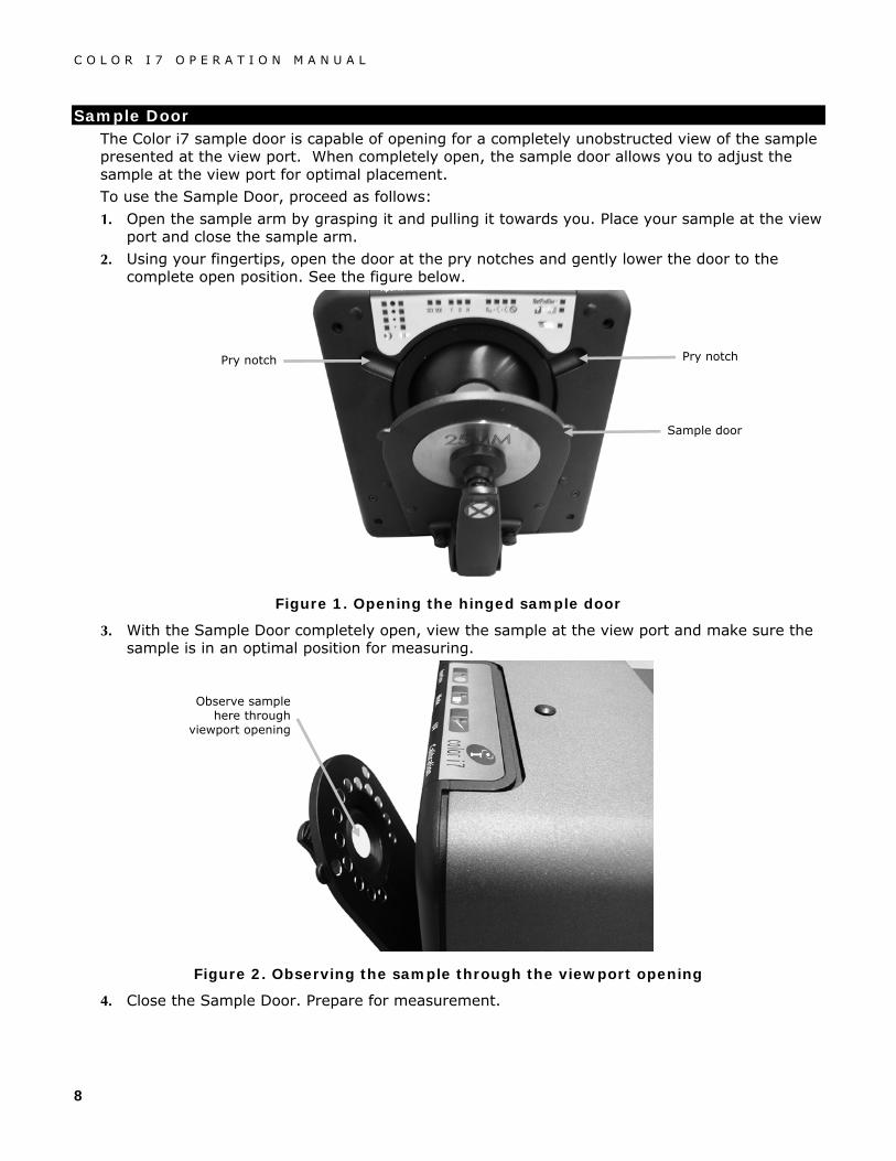
Sample Door The Color i7 sample door is capable of opening for a completely unobstructed view of the sample presented at the view port. When completely open, the sample door allows you to adjust the sample at the view port for optimal placement.
To use the Sample Door, proceed as follows:
1. Open the sample arm by grasping it and pulling it towards you. Place your sample at the view port and close the sample arm.
2. Using your fingertips, open the door at the pry notches and gently lower the door to the complete open position. See the figure below.
Figure 1. Opening the hinged sample door
3. With the Sample Door completely open, view the sample at the view port and make sure the sample is in an optimal position for measuring.
Figure 2. Observing the sample through the viewport opening
4. Close the Sample Door. Prepare for measurement.
Pry notch Pry notch
Sample door
Observe sample here through
viewport opening

C O L O R I 7 O P E R A T I O N M A N U A L
9
Computer Monitor Used for Sample Preview This preview option was installed at the time of instrument setup. To use the option press the Preview button on the spectrophotometer to view an image of the sample at the Ci7 viewport on your PC monitor. If you are using Color iControl software, make sure that you check the box: ENABLE SENSOR READ BUTTON/PREVIEW SUPPORT on the Spectrophotometer Installation Wizard screen to make sure this button is activated.
Optional LCD Sample Preview Monitor
An optional sample preview monitor is available to use with your spectrophotometer. Using a camera within the spectrophotometer, a live picture of your sample is taken at the view port. The camera then projects the live image onto the preview monitor. This is helpful since you can adjust your sample placement at the view port for targeting purposes using the monitor to guide your adjustment.
Installing the LCD sample preview monitor:
1. Remove the monitor and cabling from any shipping/packaging material.
2. Remove the Preview Monitor mounting screw cap located next to the Status Panel on the top of the instrument. The mounting screw hole should now be exposed.
3. Align the mounting screw on the monitor stem to the mounting screw hole on the instrument. Rotate the entire monitor assembly around until the monitor is secure.
4. Use the adjustment knob on the monitor stem to pivot the monitor around the ball joint to adjust the angle of the monitor for your viewing needs.
Figure 3. Preview sample monitor
5. Connect the DIN-8 connector from the Preview Monitor to the DIN-8 connector on the supplied cable.
Power switch
When activated, a live image of a sample at the view port appears.
Monitor adjustment knob
Monitor stem
Ball joint

C O L O R I 7 O P E R A T I O N M A N U A L
10
6. Connect the yellow connector on the cable to the video out connection at the rear of the instrument.
7. Connect the black connector on the cable to the monitor power connection at the rear of the instrument.
NOTE: The white and red connectors on the cable are not required for this installation.
Figure 4. Monitor cable connections
8. Press the power button on the side of the monitor to turn it on. When powered on, whatever sample is currently on the view port is seen on the display.

C O L O R I 7 O P E R A T I O N M A N U A L
11
OPERATION
Status Panel
Figure 5. Color i7 front status panel
Programmable Status Panel Buttons Standard and Trial buttons are available but must be supported by your application software and function as programmed.
The Sample Preview button is used with the Computer Monitor Video Preview.
Standard button
Preview button
Trial button
NetProfiler: Green (enabled) Yellow (not enabled) Blank (not NetProfiler) Blinking (run NetProfiler again)
Instrument Modeling
Calibrated: Red (uncalibrated) Green (calibrated)
LAV (25)
17 mm
MAV (22)
SAV (6)
Total
Direct
Haze Excluded
Adjusted Position 2
Adjusted Position 1
D65 Illuminate
Specular Excluded
Specular Included

C O L O R I 7 O P E R A T I O N M A N U A L
12
Calibration Calibration is recommended every 8 hours of spectrophotometer operation. Each spectrophotometer configuration that is used should be calibrated. A configuration consists of four components:
• Measurement Mode: Transmission, Reflectance, or Haze
• Aperture size (6mm, 10mm, 17mm, or 22/25mm)
• Specular included or excluded condition (SCI or SCE)
• UV included or excluded condition
Reflectance Calibration Procedure To calibrate your spectrophotometer in Reflectance Measurement Mode you need to use your application software. Follow these steps:
1. Launch the calibration process from the software interface.
2. You will be prompted to present and then remove the calibration tile and to prepare for the black trap.
3. Once the calibration process is complete, the Calibrated LED becomes lit. Any change to the spectrophotometer configuration may result in the calibration LED turning from green (calibrated) to red (not calibrated). Remember that each configuration needs to be calibrated.
Transmission Calibration Procedure
To calibrate your spectrophotometer in Transmission Measurement Mode you need to first locate the following items in your transmission kit box:
• Barium Coated Aperture Plate
• Transmission Sample Holder
• Black Plastic Blocking Panel
1. Using your application software launch the calibration process from the software interface.
2. Mount the Barium Coated Aperture plate to the measurement port at the front of the instrument. Follow any prompts from the software regarding the white calibration.
3. When you are prompted for the Black Calibration, place the Sample Transmission Holder inside the Transmission compartment and load the Black Plastic Blocking Panel in the Transmission sample holder. For more information on loading the Sample Transmission Holder in the Ci7, refer to Taking Transmission Measurements.
4. Click OK to any message for black trap calibration.
5. Once the calibration process is complete, the Calibrated LED becomes lit. Any change to the spectrophotometer configuration may result in the calibration LED turning from green (calibrated) to red (not calibrated). Remember that each configuration needs to be calibrated.

C O L O R I 7 O P E R A T I O N M A N U A L
13
Taking Reflectance Measurements To take a measurement using your spectrophotometer, follow these steps to ensure an accurate reading.
1. Prepare your sample for measurement.
2. Open the sample arm on the spectrophotometer to the fully open position. Present the sample at the view port and slowly close the sample arm. The spring on the sample arm is dampened to prevent the arm from closing with too much force and possibly damaging the sample.
3. Use the preview monitor, your computer screen, or the drop down door to view the sample and adjust the sample measurement targeting area.
4. Trigger the measurement using one of the following methods:
a. Select "Measure Standard" or "Measure Trial" from your application software interface. Follow the software instructions for loading the sample at the view port.
OR
b. Press the Standard or Trial button on the Color i7 Status Panel.
5. The measurement is taken. The data are presented to you in your application software. Follow the instructions for saving the data in the software.

C O L O R I 7 O P E R A T I O N M A N U A L
14
Taking Transmission Measurements An optional accessory for the Color i7 spectrophotometer is the Transmission Kit. You will need this kit in order to take transmission measurements. Please refer to Optional Accessories for more information on the Transmission kit.
Before taking a transmission measurement:
1. Set the Color i7 to Transmission Mode using your application software.
2. Mount the Barium Coated Aperture plate to the measurement port at the front of the instrument.
3. Make sure the instrument is calibrated for the measurement mode.
You will notice the Transmission LED is lit on the Status Panel based on your selection in the software. The Color i7 transmission sample holder is designed to mount inside the transmission compartment. It is used to measure thin films at both the sphere (total transmission) and at the lens (direct transmission). Direct transmission is LAV measurements only. Each transmission kit contains four sample stops and clamps, and one cuvette sample holder. Choose the sample stop and clamp appropriate for your application. Note: Liquids are measured using the cuvette sample holder.
Transmission Measurement Setup
1. Remove the transmission cover shipping screw (if installed) on the side of the instrument and set it aside.
2. Open the spectrophotometer transmission cover by sliding the cover toward the rear with your fingers.
Figure 6. Spectrophotometer with Transmission Cover Partially Open
Cover screw location
Transmission cover
Front of instrument

C O L O R I 7 O P E R A T I O N M A N U A L
15
Figure 7. Transmission holder at the sphere (total measurement)
Figure 8. Transmission holder at the lens (direct measurement)
LAV, MAV, 17 mm, and SAV measurements
Front of instrument
LAV ONLY measurements
Front of instrument

C O L O R I 7 O P E R A T I O N M A N U A L
16
3. Align the sample holder base plate pins to the base plate mounting channel holes inside the transmission area. There are mounting holes in the channel at both the sphere and the lens. For total transmission measurements, position the base plate with the clamp mounting holes on the sphere side. For direct transmission measurements (LAV only), position the base plate with the clamp mounting holes on the lens side.
Figure 9. Base Plate in Total Position
Figure 10. Base Plate in Direct Position
Clamp mounting holes
Clamp mounting holes
Lens Side Sphere Side
Front of instrument
Sphere Side Lens Side
LAV ONLY measurements
Front of instrument

C O L O R I 7 O P E R A T I O N M A N U A L
17
Film Measurements
1. Attach the appropriate stop to the base plate and clamp to the carriage base with the thumb screws. For total measurements, make sure the stop is position against the sphere before tightening the thumb screws. For LAV, sample contacts the sphere. No stop is recommended.
Figure 11. Base Plate with Stop and Clamp Attached
2. Pull the clamp back and position the sample between the clamp and stop (refer to figures 6 and 7). You may want to temporarily tighten the carriage base thumb screw to hold the clap in place while positioning the sample. Slowly release the sample clamp/carriage base to secure the sample.
Liquid Measurements
1. Loosely attached the flow cell stand assembly to the carriage base with two thumb screws. A clamp is not required for this measurement.
2. Slide the flow cell stand forward and tighten the thumb screws.
3. Insert the cuvette into the flow cell stand.
Figure 12. Flow Cell Stand (Total Measurement)
Sample stop for SAV, MAV, and 17 mm. Stop not
recommended for LAV.
Sample clamp
Carriage base
Clap thumb screws (2)
Stop thumb screw (2) Carriage base thumb screw
Base plate

C O L O R I 7 O P E R A T I O N M A N U A L
18
Initiating Measurements
1. Trigger the measurement using one of the following methods:
a. Select "Measure Standard" or "Measure Trial" from your application software interface. Follow the software instructions for loading the sample at the view port.
OR
b. Press the Standard or Trial button on the Color i7 Status Panel.
2. The measurement is taken. The data are presented to you in your application software. Follow the instructions for saving the data in the software.
Taking Haze Measurements To take a Haze measurement you will usually be required to calibrate for the haze measurement first, then you will take the actual haze measurement. The only exception to this is if you were already in Haze Measurement mode using a current haze calibration. The calibration is not launched.
Follow these steps:
1. Mount the LAV aperture plate at the measurement port.
2. Select “Haze” as the measurement type within your software interface.
3. Haze Calibration is automatically launched. Follow the prompts from the software regarding loading the spectralon plaque and the black trap.
4. Once the Haze Calibration is complete you may begin to take Haze measurements.
5. Load your sample in the Transmission sample holder within the Transmission compartment.
6. Select “Measure Standard”, “Measure Trial”, or press the appropriate measure button on the Ci7.
7. Follow the prompts from the software regarding loading the spectralon plaque and the black trap.
8. If you later change the Measurement Mode to another measurement type than Haze you will be prompted to calibrate the Ci7.
UV Control Your spectrophotometer is equipped with an automated 400nm UV filter. This can be set to fully Exclude the UV portion of the light source in the spectrophotometer or can be used to calibrate and adjust the UV level, for instance to match the UV component of D65 daylight. The Color i7 supports 3 pre-selected UV calibration positions for the filter you may wish to calibrate to D65 or other levels of UV. A UV illuminant checker is provided that has been calibrated with a CIE whiteness value for true D65. Your application software will drive the UV calibrator making successive measurements until it finds the correct calibrator position to give this value.
Aperture Control To change the aperture setting on the spectrophotometer you need to use your application software and the Aperture Plates. Select an aperture setting of SAV (6mm), MAV (10mm), 17 mm, or LAV (25mm).

C O L O R I 7 O P E R A T I O N M A N U A L
19
Note: If you select an option in your application software to automatically configure the zoom lens position (lens = port), the spectrophotometer automatically moves the zoom lens whenever you change the aperture plate.
If you prefer to not have matching Area of View and Zoom Lens setting (to have a different illumination setup), do not have your application software automatically configure the lens position (lens = port). Instead, choose an alternate Lens setting such as MAV or LAV. Keep in mind that if the zoom position and the installed aperture plate do not match, the Aperture LED will blink to indicate this discrepancy.
To install an aperture plate on the Color i7, proceed as follows.
Figure 13. Mounting the Aperture Plate on the Spectrophotometer
1. Prepare the aperture plate to be installed and make sure it is nearby.
2. Open the sample arm to the fully open position.
3. Open the sample preview door. Apply pressure at the back of the plate if necessary to remove it.
4. Locate the plate to be installed and fit the aperture over the rim on the spectrophotometer. Press the new plate firmly into place. The plate is magnetized to prevent it from falling out.
5. Gently close the sample arm.
Specular Control To change the Specular Component setting on the spectrophotometer you need to use your application software. Select the desired Specular Component Setting- Included (SCI), Excluded (SCE), or Dual Mode (SCE/SCI). Be sure to save the setting. You will notice the LED for either setting (or both if you have dual mode) becomes lit based on your selection. The Color i7 simultaneously measures Specular included and Specular excluded for all reflectance measurements. Your application software should decide which measurement data to request from the spectrophotometer according to the user requirements.
Aperture rim Aperture plate
Sample arm

C O L O R I 7 O P E R A T I O N M A N U A L
20
MAINTAINING YOUR SPECTROPHOTOMETER
Cleaning the Calibration Tiles Ceramic standards (calibration tiles) are widely used in color science as standards of reflectance factor. Their principal virtue is the stability of their reflection properties. If they are to serve their intended purpose, it is necessary that the surfaces of these tiles be maintained in a stable condition. The cleaning of any precision optic risks degrading the surface. Therefore, the need for cleaning should be minimized by returning the tile to its storage case or covering it with a protective bag when it is not in use. If cleaning is required, the following procedure is recommended.
Materials Required
Camel's-Hair Brush: Available at most camera, hardware, or art supply stores.
Dust free tissue: Use a lens tissue, which meets Federal Specification NNN-P-40A, Type I or equivalent.
To remove dust, lint, and invisible gritty particles, proceed as follows:
1. Lint and other small particles are usually best observed by illuminating the tile with a diffuse light source at an angle so that the light does not produce surface glare. Inspect the tile at an angle rather than looking directly at the tile’s front surface.
2. Brush the tile's surface with a camel's-hair brush.
3. Breathe a light mist of condensed vapor at the center of the tile.
4. Immediately wipe the tile's surface lightly with lens tissue. Avoid smearing the tile with natural greases and perspiration from the hands by wiping with the untouched center part of the lens tissue.
Cleaning the Black Plastic Blocking Panel Dust on the black plastic blocking panel can be very tightly bound by static electricity. To remove the dust, blow canned air across the surface.
Cleaning the Black Trap The black trap should be cleaned from time to time to remove and dust or contamination that may collect inside.
1. Remove the base (1) from the trap (2) by turning to the left and lifting upwards.
(1)
(2)

C O L O R I 7 O P E R A T I O N M A N U A L
21
2. Look inside of the black trap to reference how the trap glass is positioned. This is important to remember when it comes time to reinstall it after cleaning.
3. Using your fingers, carefully remove the trap glass from the trap by the edges. Avoid touching the surface of the glass with your fingers.
4. Blow short bursts of clean, dry air (4) across the both surface of the trap glass and inside of
the trap.
5. Reinstall the black glass in the trap. The bottom edge of the black glass should be resting against the felt pad (5) in the bottom of the trap when positioned properly.
6. Align the base notches over the tabs in the trap and turn to the right until it snaps into
position. NOTE: The base tabs are keyed to only allow installation in one position. Make sure you do not force it on the trap.
(3)
(4) (4)
(5)

C O L O R I 7 O P E R A T I O N M A N U A L
22
COLOR SCIENCE TRAINING
X-Rite offers color management training programs to suite your needs. We also offer a variety of workshop programs at our facilities or we can come to you. The more training you have regarding color science, your instrument, and your color science software, the more optimum your color environment. For more information please visit our website www.xrite.com and click the Color Services link, or call l-800-248-9748.
Personal Color Trainer Live Remote Training • Personal Color Trainer is a live one-on-one remote training session with a color expert to
discuss the topics for your choice. The 55 minutes you receive with your Personal Color Trainer is custom fit around your industry, equipment and needs with live video and remote desktop sharing. Please visit our website www.xrite.com and click the Color Services link, or call l-800-248-9748.
Introduction to Color IQC and Consulting for Color Management • These two-hour Webex seminars provide an instruction for new users and cover advanced
features for experienced users of Color IQC software.
Color Science for Beginners
• This two-hour Webex seminar provides a brief introduction to color measurement for industrial applications.
On-Site Training and Consulting for Color Management
• If your training needs are specific to your workflow, do you have several staff members to train or you cannot interrupt production to send your staff to off-site training, have our training experts come to you.
Fundamentals of Color and Appearance Seminar
• This traveling seminar is designed for anyone involved in evaluating color and appearance of physical materials, including paints, plastics, textiles, and more. This seminar will introduce you to the basic concepts of color and appearance science and assist you in identifying the variables, which contribute to color variation in your process. You will learn instrumentation, visual and instrumental quality control, and color data communication. Please check www.xrite.com and click the Color Services link for dates and locations.
Fundamentals of Color and Appearance Reference Book
• The Fundamentals of Color and Appearance is the definitive reference book on color theory and application. You do not have to be a color expert to understand complex color concepts. This book is part of the Fundamentals of Color Course but can be purchased through the X-Rite online store found at www.xrite.com. The book contains dozens of practical and easy-to-follow tips and techniques to help you improve color matching. Also included is a handy outline to help you develop your own color control program.

C O L O R I 7 O P E R A T I O N M A N U A L
23
TECHNICAL SERVICE
In the event that you are unable to solve a problem, you may contact our Technical Service Department.
Corporate Headquarters X-Rite, Incorporated 4300 44th Street SE Grand Rapids, Michigan 49512 Phone 1 800 248 9748 or 1 616 803 2100 Fax 1 800 292 4437 or 1 616 803 2705 European Headquarters X-Rite Europe GmbH Althardstrasse 70 8105 Regensdorf Switzerland Phone (+41) 44 842 24 00 Fax (+41) 44 842 22 22 Asia Pacific Headquarters X-Rite Asia Pacific Limited Suite 2801, 28th Floor, AXA Tower Landmark East, 100 How Ming Street Kwun Tong, Kowloon, Hong Kong Phone (852)2568-6283 Fax (852)2885 8610
Please visit www.xrite.com for a local office near you.

C O L O R I 7 O P E R A T I O N M A N U A L
24
SPARE PARTS AND ACCESSORIES
The Color i7 Spectrophotometer has optional accessories that you may order by calling the Customer Service Department in the US at 1-800-248-9748. The following accessories are available:
Transmission kit: this kit includes a calibration standard, a transmission cuvette and holder, a transmission sample holder, and a storage case.
Ci7-800
LCD Video Preview Monitor A-VPM/I57LCD
Toggle Pad Subassembly with White Ceramic Backing: User-installable replacement toggle pad that includes an embedded white ceramic backing.
GM29021020
Stand for Horizontal Measurement Plane A-MA/V57
Glass LAV Aperture A-AP/GLAV57
Net Profiler Yearly Subscription NPS/Ci5
Flow Through Cell Holder kit Ci7-801
Transmission Preform Holder kit Ci7-802
Reflectance Cuvette Holder kit Ci5-801
Reflectance Preform Holder kit Ci5-800

Corporate Headquarters X-Rite, Incorporated 4300 44th Street SE Grand Rapids, Michigan 49512 Phone 1 800 248 9748 or 1 616 803 2100 Fax 1 800 292 4437 or 1 616 803 2705 European Headquarters X-Rite Europe GmbH Althardstrasse 70 8105 Regensdorf Switzerland Phone (+41) 44 842 24 00 Fax (+41) 44 842 22 22 Asia Pacific Headquarters X-Rite Asia Pacific Limited Suite 2801, 28th Floor, AXA Tower Landmark East, 100 How Ming Street Kwun Tong, Kowloon, Hong Kong Phone (852)2568-6283 Fax (852)2885 8610 Please visit www.xrite.com for a local office near you.
P/N 391232 Ver. 2-3 (5/14)