operation, modeling, control and applications of static...
TRANSCRIPT
FACTS device
Mechanical switches
Voltage source
converter
Hybrid devices
TCSC
SVC
TCPST
STATCOM
UPFC
SSSC
IPFC
STATCOM +
Energy storage
Fault current limiter
Operation, Modeling, Control and Applications of Static Synchronous Compensator: A Review
Gahzanfar Shahgholian(1) - Jawad Faiz(2) - Bahador Fani(1) – Mohammad Reza Yousefi(1) (1) Department of Electrical Engineering, Islamic Azad University Najaf Abad Branch
Esfahan, Iran [email protected], [email protected], [email protected]
(2) Department of Electrical and Computer Engineering, Faculty of Engineering, University of Tehran Tehran, Iran
Abstract— Flexible ac transmission systems (FACTS) controller can provide better control than conventional control and achieve fast control response time. Static synchronous compensator (STATCOM) is one of the key flexible ac transmission systems (FACTS) devices based on voltage source converter (VSC) technology. The controller can provide both capacitive and inductive compensation and is able to control output curr-ent over the rated maximum capacitive or inductive range independent of the ac system voltage. This paper presents a study of modeling, operation and control fundamentals of the STATCOM.
Keywords- FACTS Device; STATCOM; Damping Controller; Location; Construction.
I. INTRODUCTION Power systems are non linear systems with a wide range of
operating conditions and time varying configurations and parameters. Flexible ac transmission systems (FACTS) have been developed to improve the performance of weak ac syste-ms and enhance transmission capabilities over long ac lines. FACTS controllers can be used in all the three states of the power system, namely: steady state, transient and post transie-nt steady state. FACTS devices can regulate the active and reactive power as well as voltage-magnitude [1, 2]. Dynamic application of FACTS controllers includes transient stability improvement, oscillation damping (dynamic stability) and vol-tage stability enhancement. Facts controller can control shunt
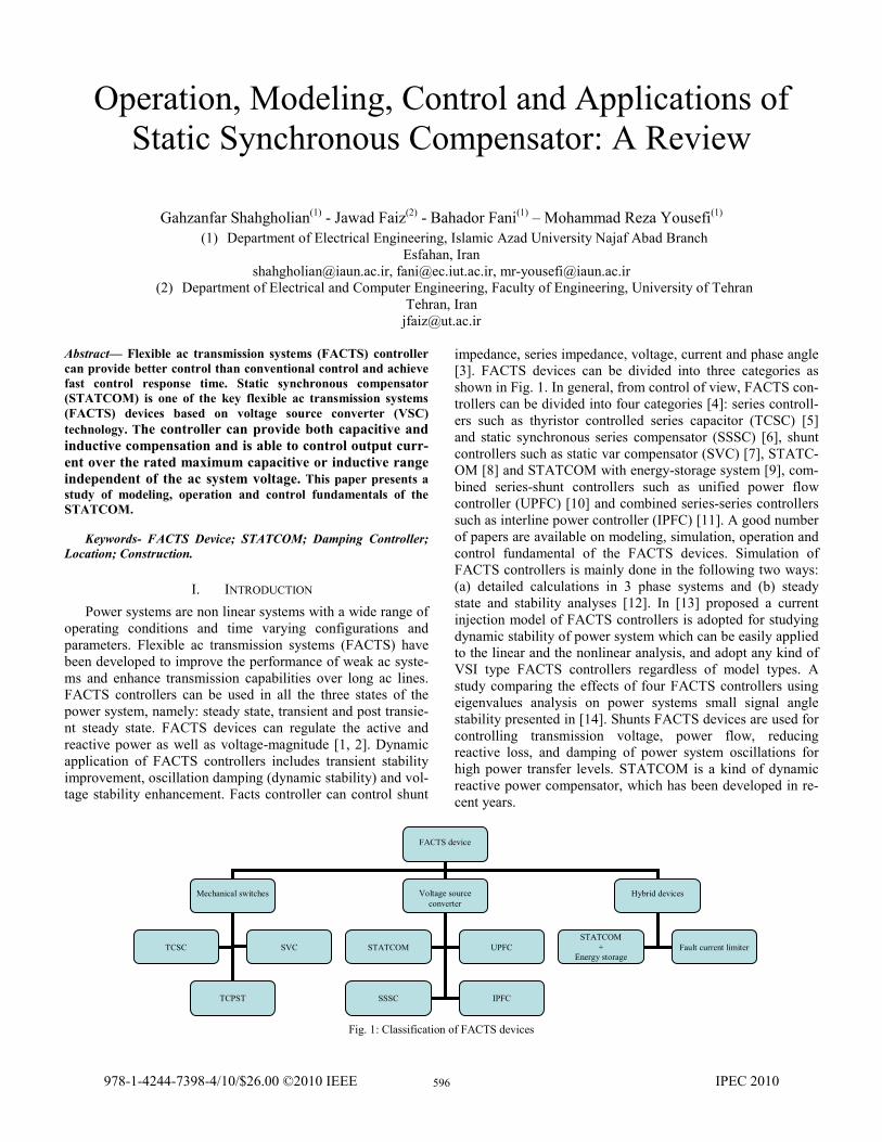
impedance, series impedance, voltage, current and phase angle [3]. FACTS devices can be divided into three categories as shown in Fig. 1. In general, from control of view, FACTS con-trollers can be divided into four categories [4]: series controll-ers such as thyristor controlled series capacitor (TCSC) [5] and static synchronous series compensator (SSSC) [6], shunt controllers such as static var compensator (SVC) [7], STATC-OM [8] and STATCOM with energy-storage system [9], com-bined series-shunt controllers such as unified power flow controller (UPFC) [10] and combined series-series controllers such as interline power controller (IPFC) [11]. A good number of papers are available on modeling, simulation, operation and control fundamental of the FACTS devices. Simulation of FACTS controllers is mainly done in the following two ways: (a) detailed calculations in 3 phase systems and (b) steady state and stability analyses [12]. In [13] proposed a current injection model of FACTS controllers is adopted for studying dynamic stability of power system which can be easily applied to the linear and the nonlinear analysis, and adopt any kind of VSI type FACTS controllers regardless of model types. A study comparing the effects of four FACTS controllers using eigenvalues analysis on power systems small signal angle stability presented in [14]. Shunts FACTS devices are used for controlling transmission voltage, power flow, reducing reactive loss, and damping of power system oscillations for high power transfer levels. STATCOM is a kind of dynamic reactive power compensator, which has been developed in re-cent years.
Fig. 1: Classification of FACTS devices
978-1-4244-7398-4/10/$26.00 ©2010 IEEE IPEC 2010596

The paper is structure as follows. The major advantages of the STATCOM over the SVC present in section II. The STATCOM operating principle and configurations is described in section III. The optimal location of FACTS devices in a power system is present in section IV. The application and modeling of the STATCOM are described in section V and VI, respectively. The damping control technique such as fuzzy controller and classic controller show in section VII. Finally, this paper concludes in section VI.
II. SHUNT FACTS CONTROLLER Shunt FACTS devices are classified into two categories,
namely variable impedance type (SVC) and switching conver-ter type (STATCOM). The voltage-current characteristic of SVC and STATCOM are shown in Fig. 2. As can be seen in the linear operating range the voltage-current characteristic and functional compensation capability of the SVC and STA-TCOM are similar.
(a) STATCOM
(b) SVC Fig. 2: Terminal characteristic of shunt controllers
The main advantage of a STATCOM over an SVC is its
reduced size, much faster response and beyond the limitation of bus voltage, which results from the elimination of ac capac-itor banks and reactors. Also STATCOM can serve as a contr-ollable current source without changing the network structure parameters and beyond the limitation of bus voltage. The cont-rol objective of the SVC is to maintain a desired voltage at the high-voltage bus. The STATCOM can supply required reacti-ve current even at low values of bus voltage, whereas the reac-tive current capability of SVC at its susceptance limits decrea-se linearly with decrease in bus voltage. The ability of STAT-COM to produce full capacitive output current at low system voltage also make it highly effective in improving the transient
stability. With proper choice of design rating and thermal desi-gn, STATCOM can have short time overload capability, enh-ance system transfer limit and improve its dynamic behavior significantly especially in the interconnected power systems. The STATCOM provides much faster response and beyond the limitation of bus voltage as compared to the SVC. The STATCOM does not employ capacitor or reactor banks to produce reactive power as the SVC do.
III. CONSTRACTION AND OPERATION The STATCOM is given this name because in a steady sta-
te operating regime it replicates the operating characteristics of a rotating synchronous compensator without the mechanical inertia. STATCOM is in principle a controlled reactive power source. It provides voltage support by generating or absorbing reactive power at the point of common coupling without the need of large external�reactors�or�capacitor�banks.�The configuration of a STATCOM connected to bus M of a transmission line is shown in Fig.3. Basically it consists of a step-down transformer (SDT) with a leakage reactance XSDT, a three-phase voltage source converter (VSC) and a dc capacitor. The STATCOM is assumed to be based on pulse width modulation (PWM) converters [15]. The operation of STATCOM is fundamentally different from that of conventional SVC.
Fig. 3: STATCOM functional model
The principle of STATCOM operation is as follows. The basic objective of a VSC is to produce a sinusoidal ac voltage with minimal harmonic distortion from a dc voltage [16]. The dc voltage across the dc capacitor (CDC) of the STATCOM is controlled to be constant for normal operation of the PWM inverter. The dc capacitor has the function of establishing an energy balance between the input and output during the dynamic change of the var output. If the compensator supplies only reactive power, the active power provided by the dc capacitor is zero. Therefore, the capacitor does not change its voltage. If the voltage magnitudes are equal, the reactive pow-er exchange is zero. The size of the capacitor is primarily det-ermined by the ripple input current encountered with the particular converter design. The charged capacitor CDC provid-es a dc voltage to the converter, which produces a set of contr-
597
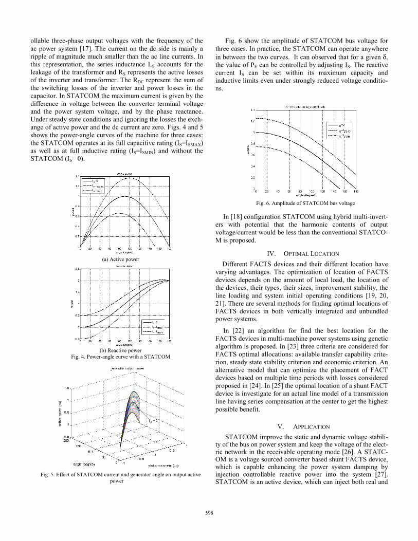
ollable three-phase output voltages with the frequency of the ac power system [17]. The current on the dc side is mainly a ripple of magnitude much smaller than the ac line currents. In this representation, the series inductance LS accounts for the leakage of the transformer and RS represents the active losses of the inverter and transformer. The RDC represent the sum of the switching losses of the inverter and power losses in the capacitor. In STATCOM the maximum current is given by the difference in voltage between the converter terminal voltage and the power system voltage, and by the phase reactance. Under steady state conditions and ignoring the losses the exch-ange of active power and the dc current are zero. Figs. 4 and 5 shows the power-angle curves of the machine for three cases: the STATCOM operates at its full capacitive rating (IS=ISMAX) as well as at full inductive rating (IS=ISMIN) and without the STATCOM (IS= 0).
(a) Active power
(b) Reactive power Fig. 4. Power-angle curve with a STATCOM
Fig. 5. Effect of STATCOM current and generator angle on output active power
Fig. 6 show the amplitude of STATCOM bus voltage for three cases. In practice, the STATCOM can operate anywhere in between the two curves. It can observed that for a given δ, the value of PE can be controlled by adjusting IS. The reactive current IS can be set within its maximum capacity and inductive limits even under strongly reduced voltage conditio-ns.
Fig. 6. Amplitude of STATCOM bus voltage In [18] configuration STATCOM using hybrid multi-invert-
ers with potential that the harmonic contents of output voltage/current would be less than the conventional STATCO-M is proposed.
IV. OPTIMAL LOCATION Different FACTS devices and their different location have
varying advantages. The optimization of location of FACTS devices depends on the amount of local load, the location of the devices, their types, their sizes, improvement stability, the line loading and system initial operating conditions [19, 20, 21]. There are several methods for finding optimal locations of FACTS devices in both vertically integrated and unbundled power systems.
In [22] an algorithm for find the best location for the FACTS devices in multi-machine power systems using genetic algorithm is proposed. In [23] three criteria are considered for FACTS optimal allocations: available transfer capability crite-rion, steady state stability criterion and economic criterion. An alternative model that can optimize the placement of FACT devices based on multiple time periods with losses considered proposed in [24]. In [25] the optimal location of a shunt FACT device is investigate for an actual line model of a transmission line having series compensation at the center to get the highest possible benefit.
V. APPLICATION STATCOM improve the static and dynamic voltage stabili-
ty of the bus on power system and keep the voltage of the elect-ric network in the receivable operating mode [26]. A STATC-OM is a voltage sourced converter based shunt FACTS device, which is capable enhancing the power system damping by injection controllable reactive power into the system [27]. STATCOM is an active device, which can inject both real and
598

reactive power to the system in a very short time and therefore has the ability to improve the damping and voltage profiles of the system [28]. A STATCOM with energy storage system such as superconducting magnetic energy storage (SMES) and battery energy storage system (BESS) can control both the rea-ctive and the active power, thus providing more flexible power system operation. Typical applications of STATCOM are low frequency oscillation (LFO) damping [29], dynamic compensa-tion and stability improvement [30], enhancement of transient stability [31], voltage flicker control [32], damping of sub syn-chronous oscillations in EHV series compensated systems [33] and power quality improvement [34],
VI. MODELING Models for power system components have to be selected
according to the proposed of the system study. A STATCOM is a multiple input multiple output variables. Several distinct models have been proposed to represent STATCOM in static and dynamic analysis [35]. In [36] shunt inverter or STATCO-M is modeled as three-phase multi pulse converter and series inverter. The different models, based on the assumption that voltages and currents are sinusoidal, balanced and operate near fundamental frequency, are proposed in [37]. Three models have been investigated for STATCOM: approximate model, detailed model and average model.
A. Approximate Model The STATCOM is modeled as a reactive current source
with a time delay. The injected current of the STATCOM is always in quadrature with its terminal voltage and dose not change the angle of the voltage at connected bus [38]. The approximate model of the STATCOM is show in Fig. 7.
(a) Mathematical model of STATCOM
(b) Power exchange operation
Fig. 7. The STATCOM principle diagram
B. Detailed Model The static power converters are nonlinear in nature and
consequently they generate harmonics into the supply. Ideally the inverter output voltage is phase with the voltage at the common connection point. The VSC converters an dc voltage (UDC) into a controllable ac output voltage uC(t) at fundament-
al frequency, with rapidly controllable amplitude (UC) and ph-ase angle (θC), behind the leakage with neglecting harmonics is:
)tsin(U)t(u CCC θ−ω= (1)
The relationship between STATCOM ac voltage UC and UDC is:
CDCRC UMkU θ∠= (2)
The equivalent model of the STATCOM is show in Fig. 8. Two control signals can be applied to the STATCOM are magnitude control (MR) and phase angle defined by PWM (θC), where MR is a factor that relates the dc voltage to the peak voltage on the ac side. The STATCOM is modeled as a VSC behind a SDT by a first order differential equation. If MR is modulation ratio defined by PWM, the voltage current relat-ionships in the STATCOM are expressed as:
DC
DCCsqCsd
DC
RDC R
U)sinIcosI(
CMk
udtd −θ+θ= (3)
where Isd and Isq are components of STATCOM current and k is the ratio between ac voltage to dc voltage depending on the inverter structure.
Figure8. Equivalent model of the STATCOM
C. Average Model in Stationary Coordinates This model based on the dq representation, is derived in
the stationary and synchronous frame of reference [39]. This model is used for the VSC and study the dynamics of theses control loops.
The circuit equivalent of STACOM in dq synchronous fra-me is given in Fig. 9, where ω is rotation speed, SD and SQ are d-axis and q-axis synchronous reference frame inverter switching function, Ucd and Ucq d-axis and q-axis are synchro-nous reference frame source voltage, iq and id are synchronous reference frame STATCOM current [40]. RS and LS mean line resistance and inductance, respectively.
599

Fig. 9. The circuit equivalent of STATCOM in qd reference frame
VII. DAMPING CONTROL STRATEGIES STATCOM can increase power system stability by dam-
ping power oscillations. Various control approaches for damping controller of the STATCOM that is a nonlinear system have been reported recently. Design of dynamic is for steady state, transient stability and eigenvalue studies.
A complete control system for STATCOM applications basically consists of two main parts: external and internal controls. The external control depends on the power system network to which the STATCOM is connected. The internal control mainly depends on the VSC topologies. An ideal internal control should instantaneously respond to a given command, which is generated by the corresponding external controller [41].
Damping controllers devised for STATCOM to improve the dynamic of power systems can be classified as continuous and discontinuous control [42].
The controllers on the basis of design and analytic approach can be divided into three main groups: a) linear such as lag-lead controllers, conventional PID controllers [43] and the linear quadratic regulators and pole assignment [44, 45], b) nonlinear such as adaptive control, particle swarm optimi-zation and loop-shaping [46], controllers by the phase compe-nsation method and fuzzy controller [47], and c) empirical such as Tabu search algorithm [48] and genetic algorithm [49].
A nonlinear controller which performance depends on the location of fault and on the location of the STATCOM is proposed in [50]. Design of a fixed parameter robust STATC-OM controller for a high order multi-machine power system through an H∞ based graphical loop-shaping procedure by embedding a particle swarm is presented in [46].
VIII. CONCLUSION A general review of classification FACTS controller
devices is presented. STATCOM is a flexible ac transmission system device, which is connected as a shunt to the network,
for generating or absorbing reactive power. STATCOM functi-ons as a synchronous voltage source. It can provide reactive power compensation without the dependence on the ac system voltage.
REFERENCES [1] H.R. Baghaee, B. Vahidi, S. Jazebi, G.B. Gharehpetian, A.Kashefi, “Po-
wer system security improvement by using differential evolution algorit-hm based FACTS allocation”, IEEE/ICPST, pp.1-6, October 2008.
[2] G. Shahgholian, E. Haghjoo, A. Seifi, I. Hassanzadeh, "The improveme-nt DSTATCOM to enhance the quality of power using fuzzy 0 neural controller", Jour. of Trans. on Elec. Tech. (JTET), Vol.2, No.5, pp.3-17,Wint. 2010.
[3] S.Sankar, S.Ramareddy, “Digital simulation of closed loop controlled IPFC using PSPICE”, Inter. Jou. of Elec. and Pow. Engi., Vol.2, pp.99-103, 2008.
[4] K.M.Sze, L.A.Snider, T.S.Chung, K.W.Chan, “Applications of PWM based static synchronous series compensator (SSSC) to enhance transient stability of power system”, IEEE/APSCOM, pp.409-413, 2003.
[5] D.Jovcic, G.N.Pillai, “Analytical modeling of TCSC dynamics”, IEEE Trans. On Pow. Del., Vol.20, No.2, pp.1097-1104, April 2005.
[6] A.M.El-Zonkoly, “Optimal sizing of SSSC controllers to minimize transmission loss and a novel model of SSSC to study transient response”, WASET, Vol.18, pp.255-261, December 2006.
[7] A.M.A.Amin, “A multilevel advanced static VAR compensator with current hysterises control”, IEEE/ISIE, pp.837-842, Slovenia 1999.
[8] G.Shahgholian, S.Eshtehardiha, H.Mahdavinasab, M.R.Yousefi, “A novel approach in automatic control based on the genetic algorithm in STATCOM for improvement power system transient stability”, IEEE/ICIS, pp.14-19, 2008.
[9] R. Kuiava, R.A. Ramos, N.G. Bretas,"Control design of a STATCOM with Energy Storage System and power quality improvements", IEEE/ICIT, pp.1-6, February 2009.
[10] C.Collins, N.Watson, A.Wood, “UPFC modelimg in the harmonic domain”, IEEE Tran. On Pow. Deli., Vol.21, No.2, pp.933-938, Apri 2006.
[11] S.Mishra, P.K.Dash, P.K.Hota, M.Tripathy, “Genectically optimized neuro fuzzy IPFC for damping madal oscillations of power system”, IEEE Trans. On Pow., Vol.17, No.4, pp.1140-1147, November 2002.
[12] D.Povh, “Modeling of FACTS in Power System Studies”, IEEE/, pp.1435-1439, 2004.
[13] J.Park, G.Jang, K.M. Son, “Modeling and control of VSI type FACTS controllers for power system dynamic stability using the current injection method”, Inte. Jou. of Con., Aut., and Sys., Vol. 6, No.4, pp.495-505, August 2008.
[14] M.S.Castro, A.B.Nassif, V.F.Costa, L.C.P.Solva, “Impacts of FACTS controllers on damping power systems low frequency electromechanical oscillations”, IEEE/PES, pp.291-296, 2004.
[15] A.S.P.Kanojia, B.V.K.Chandrakar, “Damping of power system oscillations by using coordinated tuning of POD and PSS with STATCOM”, WASET, Vol.38, pp.918-923, February 2009.
[16] N.Mithulananthan, C.A.Canizares, J.Reeve, G.J.Rogers, “Comparison of PSS, SVC, and STATCOM controllers for damping power system oscillations”, IEEE Tran. On Pow. Sys., Vol.18, No.2, pp.786-792, May 2003.
[17] M.G.Molina, P.E.Mercado, “Controller a static synchronous compensator with superconducting magnetic energy storage for applications on primary frequency control”, Latin Americaan Applied Research, pp.119-126, 2004.
[18] S.Fukuda, D.Li, “A static synchronous compensator using hybrid multi inverters”, IEEE/PESC, pp.4644-4648, 2004.
[19] S.Gerbex, R.Cherkaoui, A.J.Germond, “Optimal location of FACTS devices to enhance power system security”, IEEE/PTC, Vol.3, pp:P.7, June 2003.
[20] P.Sidhartha, R.N.Patel, “Optimal location of shunt FACTS devices in long transmission lines to improve transient stability”, Inter. Jour. Of Elec. Engi. Educ., Vol.46, No.2, pp.150-163, April 2009.
[21] S. Panda, R.N.Patel, “Optimal location of shunt FACTS controllers for transient stability improvement employing genetic algorithm”, Electric Power Components and Systems, Vol. 35, No. 2, pp. 189-203, 2007.
600

[22] L.J.Cai, I.Erlich, G.Stamtsis, “Optimal choice and allocation of FACTS devices in deregulated electricity market using genetic algorithms”, IEEE, 2004.
[23] S.Gerbex, R.Cherkaoui, A.J.Germond, "Optimal location of multi-type FACTS devices in a power system by means of genetic algorithms," IEEE Trans. Pow. Sys., Vol.16, pp. 537-544, August 2001.
[24] Z.Yu, D.Lusan, “Optimal placement of FACTs devices in deregulated systems considering line losses”, Inter. Jour. of Elec. Pow. & Ener. Sys., Vol.26, No.10, pp.813-819, December 2004.
[25] P.R.SHARMA, A.Kumar, N.Kumar, Optimal location for shunt connected FACTS devices in a series compensated long transmission line”, Turk J Elec Engin, Vol.15, No.3, pp.321-328, 2007.
[26] W.Chao, Z.Yao, “Approach on nonlinear control theory for designing STATCOM controller”, IEEE/ICGSIS, pp.871-875, November 2007.
[27] D.Murali, M.Rajaram, “Transient energy analysis for STATCOM and SSSC applications”, Inter. Jour. of Elec. And Pow. Engin., No.3, pp.191-197, 2009.
[28] M.F.Kandlawala, A.H.M.A.Rahim, “Power system dynamic performan-ce with STATCOM controller”, IEEE/TEM, pp.1-5, April 2001.
[29] K.Prasertwong, N.Mithulananthan, “Conventional and fuzzy logic controllers at generator location for low frequency oscillation damping”, Inter. Jour. of Elec. Pow. and Ene. Sys. Eng., pp.136-144, 2009.
[30] H.F.Wang, “Phillips heffron model of power system installed with STATCOM and applications”, IEE Proc.-Gener. Trans., Vol.146, No.5, pp.521-527, September 1999.
[31] A.S.AL-Baiyat, “Power system transient stability enhancement by STATCOM with nonlinear H∞ stabilizer”, Electric Power Systems Research, pp.45-52, Aril 2004.
[32] M. Torabian, R. Hooshmand, "Designing of thyristor controlled reactor compensator parameter for electric arc furnaces", Jour. of Trans. on Elec. Tech. (JTET), Vol.1, No.4, pp.53-60, Aut. 2009.
[33] B.K.Keshavan, M.Prabhu, “Damping of sub synchronous oscillations using STATCOM – A FACTS device”, IEEE/PES, Vol.1, pp.1-7, October/Noveber 2001.
[34] R.Mienski, R.Pawelek, I. Wasiak, “Shunt compensation for power quality improvement using a STATCOM controller: modelling and simulation”, IEE Proc. Gene., Trans. and Dist., Vol.151, No.2, pp.274-280, March 2004.
[35] S.F.Faisal, “Damping enhancement multimachine power system through STATCOM control”, March 2005.
[36] N.F.Mailah, S.M.Bashi, N.Mariun, I.Aris, “Simulation of a three-phase multilevel unified power flow controller UPFC”, Jour. Of Appl. Scien., No.8, pp.503-509, 2008.
[37] C.A.Canizares, M.Pozzi, S.Corsi, E.Uzunovic, “STATCOM modeling for voltage and angle stability studies”, Electrical power and energy systems, pp.1–20, 2003.
[38] M.Mahdavian, G.Shahgholian, N.Rasti, “Modeling and damping controller design for static synchronous compensator”, IEEE/ECTI-CON, pp.300-304, May 2009.
[39] V.Blasko, V.Kaura, “A new mathematical model and control of a three phase ac-dc voltage source converter”, IEEE Trans. On Pow. Elec., Vol.12, No.1, pp.116-123, January 1997.
[40] G.Shahgholian, P.Shafaghi, S.Moalem, M.Mahdavian, “Analysis and design of a linear quadratic regulator control for static synchronous compensator”, IEEE/ICCEE, pp.65-69, Dece. 2009.
[41] S.Sirisukprasert, “The modeling and control of a cascaded multilevel converter based STATCOM”, PhD Thesis, February 2004.
[42] M.H.Haque, “Stability improvement by FACTS devices: A comparision between STATCOM and SSSC”, IEEE/PES, 2005.
[43] G. Shahgholian, P.Shafaghi, S.Moalem, M.Mahdavian, “Damping power system oscillations in single-machine infinite-bus power system using a STATCOM”, IEEE/ICCEE, pp.130-134, Dece. 2009.
[44] S.Eshtehardiha, G.Shahgholian, “Improvement of STATCOM performance with optimum LQR and pole placement controller based on genetic algorithm”, First Joi. Cong. on Fuz. and Inte. Sys., August 2007.
[45] Y.Lee, S.Yung, “STATCOM controller design for power system stabilization with sub-optimal control strip pole assignment,” Inte. Jou. Elec. Pow. and Ene. Syst., pp.771-779, 2002.
[46] S.F.Faisal, A.H.M.A.Rahim, J.M.Bakhashwain, “A robust STATCOM controller for a multi-machine power system using particle swarm optimization and loop-shaping”, Inte. Jour. Of Elec. Com. And Sys. Eng., pp.64-70, Winter 2007.
[47] S.Qu, C.chen, “Low frequency oscillations damping by STATCOM with a fuzzy supplementary controller,” IEEE/ICPST, Vol.1, pp.67-70, October 2002.
[48] S.Pothiya, I.Ngamroo, S.Runggeratigul, P.Tantaswadi, “Design of optimal fuzzy logic based PI controller using multiple Tabu search algorithm for load frequency control”, Inter. Jou. of Con., Auto., and Syst., Vol.4, No.2, pp.155-164, April 2006.
[49] S.Eshtehardiha, G.Shahgholian, H.Mahmoodian, “Coordinating the multivariable state feedback controller on static synchronous compensator with genetic algorithm”, IEEE/ICIAS, pp.864-869, Malaysia, November 2007.
[50] T.Kondo, A.Yokoyama, M.Goto, H.Konishi, M.Sekoguchi, Q.Lu, “Power system transient stability enhancement by STATCOM with nonlinear control system”, IEEE/ICPST, Vol.3, pp.1908-1912, 2002.
601