operational and safety considerations for light rail dc ... · pdf file650 light rail...
TRANSCRIPT
650
LIGHT RAIL ELECTRIFICATION
Operational and Safety Considerations for Light Rail DC Traction Electrification System Design
KINH D. PHAM
Elcon Associates, Inc., Engineers & Consultants
RALPH S. THOMAS WALTER E. STINGER, JR. LTK Engineering Services
n overview is presented of an integrated approach to operational and safety issues when designing a DC traction electrification system (TES) for modern light rail and streetcar systems.
First, the human body electrical circuit model is developed, and tolerable step and touch potentials derived from IEEE Standard 80 are defined. Touch voltages that are commonly present around the rails, at station platforms, at traction power substations are identified and analyzed.
Operational and safety topics discussed include
• Applicable codes and standards for electrical safety; • Traction power substation (TPS) grounding; • Detection of ground faults; • DC protective relaying schemes including rail-to-earth voltage sensing and nuisance
tripping, and transfer tripping of adjacent substations; • TES system surge protection; • Electromagnetic and induced voltage problems that could cause disturbances in the
signaling system; • DC stray currents that can cause corrosion and damage to the negative return system,
underground utilities, telecommunication cables, and other metallic structures; and • Emergency shutdown trip stations (ETS).
To ensure safety of the project personnel and the public, extensive testing and proper and safe
equipment operation, are required. The testing includes factory testing of the DC protection system, first article inspection of critical TES components, inspection and field testing during commissioning. In addition, safety certification must be accomplished before the TES system is energized and put into operation. INTRODUCTION AND OVERVIEW The TES for a typical modern light rail or street car system includes an overhead contact system (OCS), traction power substations and feeder cables, together with associated substation protective devices, and may include supervisory control and data acquisition. The feeder cables include both the substation DC feeder cables and possible supplementary parallel dc feeders. It is important to
A
Pham, Thomas, and Stinger 651
recognize that there are fundamental differences in safety and operation between LRT and street car systems that may run on city streets, and third rail or heavy rail systems which run on a dedicated right of way where the public is well isolated from the rails and the TES. For many LRT and streetcar systems, the rails are embedded in public streets where the public can walk on the rails. Occasionally, an OCS contact wire may break and contact an OCS pole, or fall on a metallic fence, or contact and energize other metallic objects such as station shelters. Ground faults in DC feeder conductors can result in energized OCS poles or manhole lids, yet there is no common method that we know of which is capable of detecting OCS ground faults on the system, and safely isolating these faults. Indeed, we could have fault currents resulting from a very high impedance ground fault that are extremely hard to distinguish from train accelerating currents. Since the rails are purposely insulated from earth to minimize stray currents, rail-to-earth voltage must be limited to a safe level due to the touch voltages present around the rails which could be a danger to passengers and personnel. APPLICABLE CODES AND STANDARDS At present, the following electrical safety standards are available for use as a basis for design:
• IEEE Standard 80, Guide for Safety in Ac Substation Grounding, which defines methods for calculating safe touch and step potential, and is widely used in the transportation industry for traction power substation grounding.
• The National Electrical Code. • NFPA 130, Standard for Fixed Guideway Transit and Passenger Rail Systems. • AREMA, Chapter 12, “Rail Transit.” • The National Electrical Safety Code.
IEEE Standard 80 (1) deals with the recommended practice for safety grounding in high
voltage AC substations, but it was never specifically intended to apply to situations outside of AC substations such as we might find in a light rail environment. For example, tolerable limits for children in bare feet, for guide dogs for the blind, or tolerable limits for people with medical conditions or implanted electronic devices such as pacemakers are not considered.
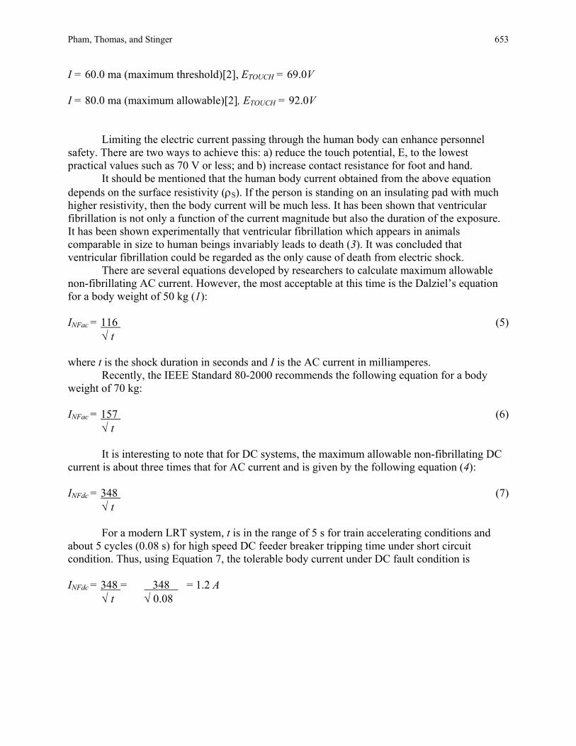
The National Electrical Code prescribes a minimum standard for electrical design that should be incorporated into the design of the TES wherever possible. HUMAN BODY CURRENT—ELECTRICAL CIRCUIT MODEL As shown in Figure 1, the human body electrical circuit includes the feet contact resistance, R1, and the internal body resistance, RB. A bare foot contact resistance is equal to 3ρS ohms, where ρS is the surface resistivity in ohm-meters underneath the foot.
For the touch potential circuit, we have two feet in parallel, the contact resistance R1 is, therefore, equal to 1.5ρS.
The touch potential is: ETOUCH = I(RB + 1.5ρS) (1)
652 Transportation Research Circular E-C058: 9th National Light Rail Transit Conference
FIGURE 1 Human body current electrical model. For the step potential circuit, we have two feet in series, the contact resistance R1 is, therefore, equal to 6ρS.
And the step potential is: ESTEP = I(RB + 6ρS) (2)
For the touch potential, consider: R1 = 1.5ρS = 1.5 × 100 ohms = 150 ohms, based upon ρS = 100 ohm-meters for surface resistivity of wet concrete floor. RB = 1000 ohms (internal body resistance for an average person, per IEEE Standard 80)
The touch potential Equation 1 becomes: ETOUCH = I(1000 + 150) = 1150 × I (3)
The current passing through the body is:
I = ETOUCH amperes (4)
I = 2.0 ma (minimum perception)[2], ETOUCH = 2.3V
Pham, Thomas, and Stinger 653 I = 60.0 ma (maximum threshold)[2], ETOUCH = 69.0V I = 80.0 ma (maximum allowable)[2], ETOUCH = 92.0V
Limiting the electric current passing through the human body can enhance personnel safety. There are two ways to achieve this: a) reduce the touch potential, E, to the lowest practical values such as 70 V or less; and b) increase contact resistance for foot and hand.
It should be mentioned that the human body current obtained from the above equation depends on the surface resistivity (ρS). If the person is standing on an insulating pad with much higher resistivity, then the body current will be much less. It has been shown that ventricular fibrillation is not only a function of the current magnitude but also the duration of the exposure. It has been shown experimentally that ventricular fibrillation which appears in animals comparable in size to human beings invariably leads to death (3). It was concluded that ventricular fibrillation could be regarded as the only cause of death from electric shock.
There are several equations developed by researchers to calculate maximum allowable non-fibrillating AC current. However, the most acceptable at this time is the Dalziel’s equation for a body weight of 50 kg (1): INFac = 116 (5) √ t where t is the shock duration in seconds and I is the AC current in milliamperes.
Recently, the IEEE Standard 80-2000 recommends the following equation for a body weight of 70 kg: INFac = 157 (6) √ t
It is interesting to note that for DC systems, the maximum allowable non-fibrillating DC current is about three times that for AC current and is given by the following equation (4):
INFdc = 348 (7) √ t
For a modern LRT system, t is in the range of 5 s for train accelerating conditions and about 5 cycles (0.08 s) for high speed DC feeder breaker tripping time under short circuit condition. Thus, using Equation 7, the tolerable body current under DC fault condition is INFdc = 348 = 348 = 1.2 A √ t √ 0.08
654 Transportation Research Circular E-C058: 9th National Light Rail Transit Conference
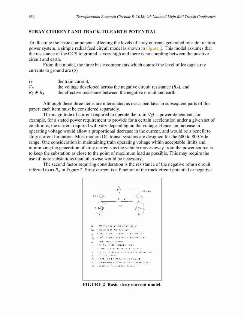
STRAY CURRENT AND TRACK-TO-EARTH POTENTIAL To illustrate the basic components affecting the levels of stray currents generated by a dc traction power system, a simple radial feed circuit model is shown in Figure 2. This model assumes that the resistance of the OCS to ground is very high and there is no coupling between the positive circuit and earth.
From this model, the three basic components which control the level of leakage stray currents to ground are (5) IT the train current, VN the voltage developed across the negative circuit resistance (RN), and RL & RS the effective resistance between the negative circuit and earth.
Although these three items are interrelated as described later in subsequent parts of this
paper, each item must be considered separately. The magnitude of current required to operate the train (IT) is power dependent; for
example, for a stated power requirement to provide for a certain acceleration under a given set of conditions, the current required will vary depending on the voltage. Hence, an increase in operating voltage would allow a proportional decrease in the current, and would be a benefit to stray current limitation. Most modern DC transit systems are designed for the 600 to 800 Vdc range. One consideration in maintaining train operating voltage within acceptable limits and minimizing the generation of stray currents as the vehicle moves away from the power source is to keep the substation as close to the point of maximum load as possible. This may require the use of more substations than otherwise would be necessary.
The second factor requiring consideration is the resistance of the negative return circuit, referred to as RN in Figure 2. Stray current is a function of the track circuit potential or negative
FIGURE 2 Basic stray current model.
Pham, Thomas, and Stinger 655 rail potential rise. This potential, VN, is the voltage developed across the negative return rail from the substation to the train and it depends on the train current (IT) and RN. There are two basic approaches to maintain the voltage developed across the negative return system within the desired limits, assuming a given propulsion power requirement: a) increase the conductance of the negative return circuit; and b) reduce the maximum distance between the load and power source as also noted above, which means spacing between traction power substations would need to be reduced, which again may result in an increase of the number of substations.
The third factor affecting the stray current magnitudes in the model of Figure 2 is the negative circuit to earth resistance, referred to as RL & RS. Theoretically, we could reduce the stray current by increasing RL &RS to very high values. Stray Current Control The following accepted rail industry methods have been used in recent rail transit system designs to control stray currents:
• Insulating pads and clips on concrete ties. • Insulating direct fixation fasteners on aerial structures. • Coating the rails and encasing the track slab with an insulating membrane where the
rails are embedded in the roadway areas. • Minimizing the stray current leakage path through rail/ballast contact by maintaining
the ballast at a minimum of 1 in. below the bottom of the rails. • Bonding rail jumpers at mechanical rail connections for special trackwork. • Cross-bonding between rails and between tracks to maintain equal potentials of all
rails. • Insulating the impedance bond tap connections from the housing case. • Insulating switch machines at the switch rods. • Utilizing separate traction power substations for the main line, yard, and shop. Shop
tracks are solidly grounded for maintenance personnel safety. • Installing rail insulators to electrically isolate the mainline from the yard and the yard
from the shop. • Placing substations near points of maximum train acceleration. • Maintaining as close substation spacing as practicable. • Increasing system nominal voltage from 600 Vdc to 750 Vdc and higher. • Maintaining electrical continuity in tunnel liners and reinforcing steel. • Maintaining an on-going maintenance program that monitors rail-to-earth resistance
values, keeps track-bed areas clean and well-drained. Track-to-Earth Voltages As mentioned earlier, stray currents can be controlled effectively by increasing the track-to-earth resistance values. However, a well-insulated negative return system may also cause the increased track-to-earth voltages depending upon other system characteristics.
The relationships between the voltages, VN, VGL, and VGS as shown in the basic circuit model of Figure 2 are summarized below (4, 5):
656 Transportation Research Circular E-C058: 9th National Light Rail Transit Conference
VGL = RL × VN (RL + RS) VGS = RS × VN (9) (RL + RS) where: VN = IN × RN (10)
The main concern that relates to this voltage is the human body’s safety from touch potential. A voltage relay (device 164N) is recommended to be connected between the negative bus and ground. This relay would trip the DC feeder breakers when the negative rail-to-earth potential becomes high to avoid a dangerous situation. As an alternate, the substation negative bus could be clamped to ground temporarily when excessive rail-to-earth voltage occurs. The rail transit industry has not standardized the acceptable limits of negative return rail potential with respect to ground. Each transit agency has set its own limits. Based on our past experiences, the maximum trip setting ranges from 60 Vdc to 90 Vdc. TRACTION POWER SUBSTATION AC GROUNDING Two basic approaches to designing grounding systems are used worldwide (3): a) In some countries, a grounding system is considered adequate when the grounding resistance is lower than a recommended value, and b) in some countries, such as the U.S., a grounding system is considered safe when step and touch potentials are lower than a permissible values. Of these two approaches, the second is more valid because magnitude of tolerable current flowing through the human body is taken into consideration. AC Ground Mat The traction power transformer, substation AC switchgear and other AC equipment enclosures including auxiliary power transformer, AC panel boards and prepackaged building frames should be connected to a substation AC ground mat designed per IEEE Standard 80-2000 with considerations for step and touch potentials. It should be mentioned that the intent of the IEEE Standard 80 is to provide guidance and information pertinent to safe grounding practices in high voltage AC outdoor substations. The following is quoted from the first page of IEEE Standard 80-2000,
This guide is primarily concerned with outdoor substations, either conventional or gas insulated. Distribution, transmission, and generating plant substations are included. With proper caution, the methods described herein also applicable to indoor portions of such substations, or to substations that are wholly indoors. No attempt is made to cover the grounding problems peculiar to DC substations. A quantitative analysis of the effects of lightning surges is also beyond the scope of this guide.
In contrary to high voltage outdoor substations where most of the equipment such as buses,
breakers, transmission towers, and so on are all exposed; all equipment inside the traction power
Pham, Thomas, and Stinger 657 substations such as 15 kV switchgear, 15 kV station service transformer, and AC panelboards are all enclosed and grounded, furthermore all this equipment is housed inside a grounded building. Hence, it is a very conservative design to follow the IEEE Standard 80 to design AC ground mats for traction power substation AC equipment. Maximum Tolerable Step and Touch Potentials By substituting Equation 6 into Equations 1 and 2, we obtain the following equations:
Tolerable touch potential for a human body of 70 kg: Etouch tolerable = 157 + 0.236 × CS × ρS (11) √ t
Tolerable step potential for a human body of 70 kg: E step tolerable = 157 + 0.942 × CS × ρS (12) √ t where ρS = the surface resistivity in ohm-meters CS = the surface layer derating factor t = the duration of fault in seconds
The surface resistivity and duration of fault are used to establish maximum tolerable step and touch potentials. High surface resistivity and fast fault clearing time will give high tolerable step and touch potentials.
Calculated Step and Touch Potentials The worst possible touch potential (called the mesh potential) occurs at or near the center of a grid mesh. Industrial practice has made the mesh potentials the standard criteria for determining safe ground grid design.
The following equations are obtained from IEEE Standard 80-2000 (1). Emesh = Km × Ki × ρ × I (13) L Estep = Ks × Ki × ρ × I (14) L
658 Transportation Research Circular E-C058: 9th National Light Rail Transit Conference
where I = maximum ground fault current in amperes. L = total length of ground grid conductors in meters. Km = mesh coefficient which takes into account spacing, diameter and depth of burial of the ground grid conductors. Ks = step coefficient which also takes into account the grid geometry. Ki = irregularity factor. ρ = soil resistivity in ohm-meters
After E-mesh and E-step of the grid are calculated, they shall be compared to the values of the tolerable touch voltage (Etouch tolerable) and tolerable step voltage (Estep tolerable) respectively to determine whether or not the designed grounding grid can be judged to be safe (6, 7).
TRACTION POWER SUBSTATION DC GROUNDING Rectifier and DC switchgear equipment enclosures should be insulated from ground and connected to a DC ground mat through either a high-resistance or a low-resistance grounding system. This paper will not discuss the advantages and disadvantages between the two grounding systems. Refer to Pham (6) for additional discussions on high versus low resistance grounding. Regardless of a high or low resistance grounding system, a positive fault to the enclosure must trip the main AC breaker and DC feeder breakers and lock-out the substation. Ample clearance should be provided between the grounded AC equipment enclosures and the ungrounded DC equipment, particularly when the high resistance grounding option is used.
Special consideration must be given to the load side of DC feeder breakers that may get energized from the adjacent substations via the OCS distribution system. Transfer trip is a very reliable method to ensure that DC power feed from the adjacent substations is removed.
The DC surge arrestor ground should be isolated from the AC ground mat and connected to a separate DC ground mat. The DC equipment and the surge arresters are rated 1000 Vdc maximum while the medium voltage equipment has a maximum design voltage of 15 kV (RMS) with a BIL of 95 kV. Connecting the DC surge arrester grounds to the AC ground mat could result in equipment failure; for example, an AC ground fault of 3500 A will raise the AC ground mat (1.0 ohm) potential to 3500 V ( 1.0 ohm × 3500 A = 3500 V). This voltage rise of 3500 Vdc far exceeds the MCOV of a 1000 Vdc rated surge arrester.
The AC ground mat and dc ground mat should be kept physically separated to limit the voltage on the DC ground mat due to transfer of potential from the ac ground mat. DETECTION OF OCS GROUND FAULTS When there is a ground fault between the OCS and ground, the area in the vicinity of the fault could be subject to a high voltage of 750 Vdc. The return circuit back to the traction power substation will be closed via the earth to track if the substation negative bus is isolated; hence, the ground fault current could be relatively low and the time it takes for the DC feeder breakers to clear the fault would be unduly long. One approach to detect the OCS to ground fault is to
Pham, Thomas, and Stinger 659 connect the substation negative bus to a separate ground mat such as the DC ground mat through a grounding diode. The diode-grounding device will provide a return path from the ground to the substation negative bus and thus enable faster fault clearing. The grounding diode will also allow leakage current to return to the substation and thus create a lower resistance path for stray current leaving the rails. However, the return stray current can be monitored, and if excessive leakage currents are detected, the grounding diode can be temporarily disconnected between the negative bus and the DC ground mat, and the source of the leakage current determined and corrected. LIGHTNING AND OVERVOLTAGE PROTECTION Lightning intensity within a specific area is generally based upon the ground flash density, Ng, in flashes per km2. However, at present within the United States this data, Ng is not generally available and the lightning severity must be based upon the isokeraunic level, or the number of thunderstorms per year, Td. The value of Ng can be approximated by using the following expression (8, 9): Ng = 0.04 Td
1.25 flashes/km2/year (15)
For example, the average number of flashes/km2/year in the Portland, Oregon, area is 0.1, while the average number of flashes/km2/year in Florida is 8. This discussion is intended to establish the lightning intensity to the OCS system components—especially the contact wire, which is protected by DC surge arresters. The various components of the OCS system, messenger wire, contact wire, supporting structure which consists of metallic poles, cross-arms, and the running rails are relatively close to each other. There are equal chances that the lightning stroke may hit any of the OCS components described above.
The cross-arms and grounded metallic poles may provide some measure of shielding of the OCS contact wire from a direct lightning stroke. In rare circumstances, if the lightning strikes the OCS wire directly, flash over is almost certain since the dry and wet flashover values of the OCS insulators are normally relatively low as compared to the direct hit lightning stroke peak voltage which could be as high as 200 kV.
The following equation has been used in power distribution overhead lines and can be used to calculate the discharge current and energy for the OCS surge arresters (8): IA = (ES – EA)/Z (16) where EA = arrester switching impulse discharge voltage (kV) for current IA ES = prospective switching surge voltage (kV) Z = surge impedance of the OCS wire (Ω), and IA = switching impulse current (kA)
Energy discharged by the arrester, J, in kJ, may be conservatively estimated by the following expression (8):
660 Transportation Research Circular E-C058: 9th National Light Rail Transit Conference
J = 2 DL EA IA /v where EA = arrester switching impulse discharge voltage (kV) IA = switching impulse current (kA) DL = line length (miles or feet) or (km) v = the speed of light (190 mi/ms) or (300 km/ms) or 1000 ft/µs
The expression assumes that the entire line is charged to a prospective switching surge voltage and is discharged through the arrester during twice the travel time of the line. DC surge arrester data including energy discharge capability, peak voltages, and currents should be reviewed carefully and compared with the analysis results. The numbers and locations of the surge arresters can be recommended based on the above analysis. As a minimum, surge arresters should be provided at each substation or OCS feed point connection and in low OCS clearance areas. INDUCED VOLTAGE An energized overhead power line that carries current produces an electric field and a magnetic field around the conductor and into the surrounding spaces. These electromagnetic fields may induce voltages and currents onto the metallic track rails and other nearby conductors. The electromagnetic fields are non-uniform near the power lines. The electric field intensity is dependent upon (proportional to) the power line operating voltage, while the magnetic field strength is dependent upon (proportional to) the power line current. Because the electric field is stronger and non-uniform near the power line, different voltages will exist at different points within this region. Conductors within this region will perturb the electric field and develop a voltage gradient of their own. In AC power line installations where the magnetic field is time varying, that is, it is continually expanding and collapsing, a longitudinal electromotive force (LEF) will be induced in nearby conductors.
In this discussion, we will distinguish between induced voltages, which are a result of electric fields, and induced voltages (and currents), which result from the magnetic field interaction. In a DC distribution system, the voltage induced in the region near the conductor is time independent except for the noise component and the longer time varying DC load component. The correct term for the DC case is electric potential difference or electrostatic potential difference. In an AC distribution system, the electric and magnetic fields are alternating, as are the induced voltages and currents in the conductors. The correct term for the AC case is electromagnetic field induction or electromagnetic coupling.
Power wires, signal wires, track rails, and conduits that are located near overhead power lines, are considered to be “disturbed conductors” and will develop different voltages with respect to each other and with respect to reference ground.
The electric field, which exists along a disturbed conductor, is directed perpendicular to the conductor. The strength of the electric field at any point varies inversely with the distance from that point to the conductor. This effect in the low voltage circuit wires can be minimized if these wires have simple coaxial shields with drains to ground, or are buried.
Pham, Thomas, and Stinger 661
The magnetic field, which exists along an overhead power line, can cause a longitudinal voltage to be induced into a parallel power line or signal conductor. Ferromagnetic materials, such as iron or steel, provide for effective shielding against magnetic fields. Such materials, when used in the conduits that carry insulated conductors inside, will reduce the strength of the magnetic field and thus its induction effect. Steel conduit provides a high degree of shielding against magnetic fields.
Magnetically induced voltages can be attenuated by the development of a counter-electromotive force (EMF). Counter-EMF can be generated and introduced onto a conductor in a manner that will tend to cancel the effect of the disturbing electromagnetic field. Coupling energy from the source of counter-EMF may be accomplished with transformers known as neutralizing transformers or by direct coupling between the “shield wire” and the disturbed wire.
The close presence of an overhead power line provides some shielding effect from direct lightning strikes in the immediate vicinity of the line. However, surge voltages can be induced onto the signal circuits from the power line as a result of switching and lighting strikes occurring at a distant location perhaps many miles from the light rail facilities. Surge arrestors should be used to reduce these unwanted effects. Also, utility fault currents will cause voltages to be induced in nearby light rail circuits. The magnitude of these voltages will be much larger than what the normal induced voltages are along the light rail circuits.
Normal induced voltages exist at 60 Hz and higher harmonics. Low and medium voltage (up to 34 kV) line faults are also 60 Hz. High voltage transmission line faults have components in the 40 to 400 kHz range. Switching surges develop frequencies up to 1.5 MHz. Lighting generates surges with steep wave fronts with frequencies around 1.5 MHz.
Induced voltages and currents that are found on signal circuits may create a safety hazard to personnel, equipment, and service.
Induced voltages may cause equipment to malfunction. Equipment operations may happen when they should not, or equipment may be inhibited from operation when it should operate. Equipment damage may also occur from fused electrical contacts or from punctured insulation. Any of these situations may result in the impairment of safe train movement and costly inconvenient service interruption.
The following LEF objectives are recommended for the protection of personnel (10–12):
1. According to the National Electrical Safety Code, electrostatic voltage must be limited such that a short circuit current between a disturbed circuit and ground will not exceed 5 mA.
2. The following LEF objectives are generally accepted by the electric power utilities and the railroads for the protection of personnel as established by the Association of American Railroads and the Edison Electric Institute Joint Committee. For coordinating the location of the light rail facilities with the electric power utilities, the following maximum voltages apply to the light rail (disturbed line) circuits:
• 60 V RMS residual is acceptable for normal operating conditions. • 150 V RMS is acceptable to exposed sections where special instructions are given to the personnel authorized to have access to the exposed sections and special markings appear on all equipment connected to the exposed sections. • 430 V RMS is acceptable for usual power line equipment and maintenance. • 650 V RMS is acceptable for highly reliable power lines where high-speed relaying and fault clearing is provided.
662 Transportation Research Circular E-C058: 9th National Light Rail Transit Conference
These voltage objectives originate from the international telecommunications field and are presented here for personnel safety, not for equipment environment. The voltage objectives for equipment must be developed through the exercise of engineering judgment.
A personnel safety hazard is created when there is a complete circuit path developed and any of the following conditions occur:
• A person comes into contact with a conductor having an induced voltage sufficient to cause a dangerous current to flow through his body.
• A person comes into contact with a high voltage conductor and the duration of the high voltage-causing event is sufficiently long in duration to be physiologically dangerous.
• A person comes into contact with a ground-return circuit. • A person comes into contact with a circuit that is accidentally grounded. • A person comes into contact with a circuit that is effectively grounded through a
capacitance.
The disturbed conductors and circuits could fall into one or more of the following general categories:
• Rails and contact wire. • Railroad signal and communications circuits. • Railroad conduit.
Because the signal circuits are meant to be isolated from earth potential, a shock hazard
will be present only if the conductor capacitance to ground is large enough to allow a voltage to be built-up or if one side of the circuit becomes accidentally grounded.
The danger to personnel is related to the amount of current through the human body, which depends upon the total resistance of the path between the conductor and reference ground. The total resistance includes the contact resistance between the ground contact to reference ground (resistance of earth), resistance of the human body, and contact resistance between the human body and conductor. The danger increases when the resistance of the human body becomes a large fraction of the total resistance of the ground return path.
The amplitude of voltage a person will experience will depend on whether the contacted circuit is grounded or not and where the point of contact is. Electrostatic induced voltage is usually a low energy phenomenon and can be controlled with nominal cable shields. The duration of an electrostatic discharge current through the human body is likely to be below the danger level.
The recommended safety measures to be taken by construction and maintenance personnel are as follows:
• All personnel should be instructed concerning the hazard voltages present at all times and should be required to follow safe working practices.
• The rails and OCS are long metallic conductors and a significant voltage may be developed on them when paralleling an overhead power line. Personnel performing work on them should be made aware of the potential danger and should be cautious with respect to electric shock.

Pham, Thomas, and Stinger 663
• The track rails are unshielded and present day practice is to attempt to isolate rails from earth to minimize stray currents. Although the OCS provides some shielding, significant voltage may still be developed along the tracks under an electrical fault condition.
• Safety grounding practices should be employed when working on OCS and insulated protective gear used when working on track. The rails must not be connected to ground, which would compromise signaling and stray current measures.
It is important to recognize that the OCS will have an induced voltage present at all times, even if all power sources are disconnected. Construction and maintenance personnel must exercise caution whenever working on a section of the OCS. Safety grounds should be used at the location where work is being performed. If workmen must come into contact with the OCS involving a continuous section of more than one span, safety grounds should be applied at each end of the work area and at all points of catenary support within the work area. Grounding both sides of the work area is a necessary requirement for personnel safety. SUBSTATION PROTECTIVE DEVICES AND CONTROLS As a minimum, the following substation protective devices should be provided. Medium Voltage Switchgear Phase over-current relays, residual ground over-current relay, phase balance current relay, and under voltage relays should be provided with medium voltage switchgear. Rectifier Transformer Transformer winding temperature devices should be provided. Power Rectifier Rectifier diode temperature device, diode fuse, rectifier diode fuse monitoring device, and rectifier enclosure fault detection relays should be provided. DC Switchgear Protective relays associated with DC switchgear should include reverse current trip device, over-current trip and rate-of-rise relays, reclosing and load measuring devices, transfer trip, rail-to-earth over-voltage and DC switchgear enclosure fault detection relays. Transfer Trip Protection Transfer trip protection is highly recommended for the DC feeder breakers since this will be a reliable additional protection to ensure that faults in the DC traction power system are completely isolated and fault currents are not fed from the adjacent substations.
664 Transportation Research Circular E-C058: 9th National Light Rail Transit Conference
EMERGENCY SHUTDOWN SWITCH AND BLUE LIGHT STATIONS History NFPA 130, “Standard for Fixed Guideway Transit and Passenger Rail Systems,” was initially developed by the National Fire Protection Association in 1975. The purpose of the standard is to minimize “the potential for entrapment and injury of large numbers of people who routinely utilize …mass transit facilities.” Applicability NFPA 130 applies to all fixed guideway systems, including at-grade, tunnels, and aerial structures. The degree of applicability and interpretation is decided by the transit agency in partnership with local fire and emergency or rescue authorities in accordance with NFPA 130, Chapter 7 (2000), which states in part:
General. The authority that is responsible for the safe and efficient operation of a fixed guideway transit or passenger rail system shall anticipate and plan for emergencies that could involve the system. Participating agencies shall be invited to assist with the preparation of the emergency procedure plan.
Ideally, the emergency plan has been developed and incorporated into the design criteria
before the beginning of the Civil/Systems final design since the emergency procedures plan may mandate design requirements. If the plan is not in place, or is being developed concurrently with the design, interpretation of NFPA 130 may be left to the designers. NFPA 130 Requirements for Blue Light Stations The 2000 edition of the NFPA 130 3-1.5 reads (in part) as follows:
3.1.5 Blue Light Station 3-1.5.1 A location along the trainway, indicated by a blue light, where emergency service or authorized personnel can communicate with the central supervising stations and disconnect traction power. Traction power disconnect devices shall allow quick removal of power from power zones. Emergency shutoff of traction power shall be achieved by activation of remote manual-control devices, which, in turn, cause the operation of substation circuit breakers and associated trackway disconnect devices. 3-1.5.3 Blue light stations shall be provided at the following locations: (1) Ends of station platforms (2) Cross passages (3) Emergency access points (4) Traction power substations
NFPA 130 A3-1.5.3 reads as follows: A3-1.5.3 The placement of blue light stations at the ends of station platforms should be governed on actual need. For instance, an at-grade system that has
Pham, Thomas, and Stinger 665
stations in dedicated streets and overhead power supply would not need blue light stations at the ends of platforms.
The traction power disconnect devices referenced by NFPA 130, above, are commonly
referred to as ETS or Emergency Shutdown Stations (ESS). Industry Experience In an attempt to categorize industry experience in how they interpreted the NFPA 130 requirements for blue light stations, and in particular where agencies were providing hard wired traction power emergency disconnect devices, we surveyed all LTK TES engineers, and contacted several transit agencies. Our findings are summarized as follows:
• With some exceptions, blue light stations with a manually actuated hard-wired TES ETS are provided for third rail systems at passenger stations. This appears to be true both in the USA and foreign countries. These stations are usually accessible to the general public, and may be of the “break-glass” types. NFPA 130 does not state the reason, but it appears to be related to the urgency to shut down the third rail should a passenger fall into the pit at a station.
• With some exceptions, blue light stations with either a manually actuated hard-wired TES ETS or an emergency communications telephone are provided in tunnels and on aerial structures for both third rail systems and OCS LRT systems.
• With very few exceptions, hard-wired TES ESS are not provided for at-grade OCS systems for LRT or electric trolley systems either along the alignment or at station platforms. Indeed, most agencies do not provide blue light stations for OCS systems. From a practical standpoint, central control may be contacted directly by emergency personnel using cellular telephone or radio. The need for a direct line from a station platform to central control is greatly reduced. Also, it is difficult to conceive of a situation where the general public would need to shut down the system in the event of an emergency.
• With no exceptions, ESS is installed at each traction power substation location for both light rail and heavy rail systems. SUBSTATION VENTILATION We know that substations contain arcing devices such as circuit breakers and switches that produce ionized gas and batteries which can produce hydrogen. Some electrical insulation can produce explosive gas when burned. An adequate ventilation system for the inside of the substation building is therefore very essential. Ventilation ductwork and fans must be sized to handle the heat losses generated by the substation equipment. Filters and louvers should be provided to filter outside air.
Mechanical cooling (air-conditioning) may be used to cool substations in warmer climates and to supplement ventilation, but should not be used exclusively, since some ventilation is required to remove explosive gases.
666 Transportation Research Circular E-C058: 9th National Light Rail Transit Conference
SUBSTATION OPERATION AND MAINTENANCE From the perspective of traction power substation maintainers, convenient access to equipment for servicing and maintaining, sufficient working space around equipment, protection from the weather, and adequate lighting are essential for maintaining and operating the substations. Equipment rear access should be taken into consideration. For built-in-place substations, an aisle should be provided behind the equipment with two means of egress and with panic hardware on the man doors. For packaged units, rear access to equipment may involve the removal of access panels using heavy equipment, and access needs to be provided accordingly.
Many electric utilities now require significant space behind their utility incoming cubicle for rear access and cable maintenance, and the attachment of grounds to the equipment bus using a “hot stick.” This may necessitate a door and access to the rear of the cubicle from the outside of the substation.
Substation maintenance may involve taking the traction power substation out of service. A means to over-ride SCADA (remote substation control and data acquisition) should be provided. Consideration needs to be given to the function of substation protective devices such as transfer trip when the substation is off line and the OCS tie switches are closed. RECOMMENDATIONS Development of a TES must be approached in a fully integrated manner. All of the concepts discussed in this paper must be considered as they relate to each other. The goals for the TES must be both determined and accepted early in the design of a total project.
The following should be included in the integration effort: • Car propulsion system design that minimizes rail rise and line current draw under
abnormal conditions. • Early and often use of comprehensive computer simulation to optimize TPS size,
number, and location, and OCS sizing when it is possible to influence these elements. • Coordination among corrosion mitigation requirements, step and touch potential,
sensing and clearing of remote ground faults, inductive interference effects, and railway signaling requirements.
• Track, grounding, and ground system configuration and parameters. • Operational requirements, track configuration, OCS sectioning, and sectioning
methodology. Design Recommendations
• Provide a means of OCS remote ground fault detection and tripping; • Minimize rail potential rise by decreasing substations spacing and reducing the size of
substations and by increasing system voltage as appropriate; • Adopt and follow the National Electric Code as closely as possible, especially for
minimum working clearances; and • Provide adequate ventilation to remove explosive gases from the substation.
Pham, Thomas, and Stinger 667
The following testing recommendations are made:
• Include design demonstration and thorough qualification testing of the critical TES components and the TPS control system, including DC protective relays;
• Installation, commissioning, field testing and inspection should include ground fault testing, short circuit testing, and testing and setting of each substation protective system;
• Attain safety certification before the TES system is put into operation; • Consider safety for step and touch potentials at the substations, around the rails, and
at the station platforms; and • Forensic data is needed to understand how TES systems fail in service in order to
make design improvements; perhaps even legislation is needed that requires agencies to report more serious failures (IEEE Traction Power Substation Standards Sub-committee is presently working on this). ACKNOWLEDGMENT The authors thank the management at LTK Engineering Services and Elcon Associates, Inc. for their support in the preparation of this paper. REFERENCES 1. IEEE Guide for Safety in AC Substation Grounding, ANSI/IEEE Standard 80-2000. 2. Moody, K. J. Stray Current Control and Platform Voltages. Proc., APTA Rapid Transit
Conference, Pittsburgh, Pa., 1989. 3. Jacimovic, S. D. Rail Potential Rise and Public Safety. APTA paper. 4. Dev Paul. Operation Safety and Maintenance Considerations for People Movers’ DC
Grounding Systems. Proc., APTA Rapid Transit Conference, Buffalo, N.Y., 1988. 5. Pham, K. D., R. S. Thomas, and W. E. Stinger. Analysis of Stray Current, Track-to-Earth
Potentials, and Substation Negative Grounding in DC Traction Electrification Systems. Proc., IEEE/ASME Joint Rail Conference, 2000.
6. Pham, K. D. Grounding of Traction Power Substations. Proc., APTA Rapid Transit Conference, Pittsburgh, Pa., 1989.
7. Pham, K. D., and R. S. Thomas. Design of Grounding Systems for Tri-Met Portland Westside Light Rail Traction Power Substations. Proc., IEEE/ASME Joint Rail Conference, 1999.
8. Dev Paul. Light Rail Transit DC Traction Power System Surge Overvoltage Protection. IEEE Transactions on Industry Applications, Vol. 38, No. 1, Jan.–Feb., 2002.
9. IEEE Guide for Improving the Lightning Performance of Electric Power Overhead Distribution Lines. IEEE Standard 1410-1997.
10. National Electrical Safety Code. 11. AREMA, Chapter 12, Rail Transit. 12. TriMet. Signal System Westside EMI Report. Portland, Oreg., 1993.
668 Transportation Research Circular E-C058: 9th National Light Rail Transit Conference
BIOGRAPHICAL SKETCHES Kinh D. Pham is a VP/Project Manager with Elcon Associates, Inc., Consulting Engineers, in Portland, Oregon. He has worked on rail transit projects since 1981 and is Traction Electrification Manager for TriMet’s Interstate MAX light rail extension. He is a professional engineer registered in Oregon and eight other states. A senior member of IEEE, Kinh earned his BSEE degree from Portland State University, an MSEE degree from the University of Portland, and did his doctoral studies at PSU. Walter E. Stinger, Jr. is a senior systems engineer with LTK Engineering Services. He has worked on numerous rail transit projects for the past 36 years. A registered professional engineer in Alberta, Canada, Walt received his BSEE degree from Drexel University in 1964. Ralph S. Thomas is a senior systems engineer with LTK Engineering Services in Portland, Oregon. He has worked on rail transit projects since 1981 and was Traction Electrification Manager for TriMet’s Westside Light Rail. He is a professional engineer registered in Oregon and four other states. He received his BSEE degree from Portland State University.