operational concept for initial integrated collaborative ... · operational concept for initial...
TRANSCRIPT
MITRE: MP 06W0000098 METRON AVIATION: 32F0506-003-R0
Operational Concept for Initial Integrated Collaborative Rerouting (ICR)
May 2006
N. J. Taber, MITRE/CAASD G. E. Wilmouth, Metron Aviation, Inc. G. J. Jacobs, MITRE/CAASD
The contents of this document reflect the views of the authors, Metron Aviation, Inc., and The MITRE Corporation and do not necessarily reflect the views of the FAA or the DOT. Neither the Federal Aviation Administration nor the Department of Transportation makes any warranty or guarantee, expressed or implied, concerning the content or accuracy of these views.
©2006 The MITRE Corporation and Metron Aviation, Inc. All Rights Reserved.
Center for Advanced Aviation System Development McLean, Virginia Herndon, Virginia

ii

iii
Acknowledgments
The authors would like to thank the members of the Future Concepts of Flow Management Sub-Team and the many operational personnel who attended the exercises and group discussions. They provided innovative ideas and valuable feedback that helped define and clarify the operational concept presented here. Thank you also to Cheryl Mayson Shaffer for graphics support, and to Joan Arnold and Kathleen Menéndez for help in preparing this document for publication.

iv

v
Table of Contents
1 Introduction 1-1 1.1 Background 1-1
1.2 Document Organization 1-3
2 Initial ICR Operational Concept 2-1 2.1 Constraint Sharing via Planning Route Advisory 2-1
2.2 Generating/Analyzing Reroute Options 2-9
2.3 Submitting Customer Preferences via Early Intent 2-11
2.4 Evaluating System Impacts of Customer Preferences 2-12
2.5 Implementation and Monitoring 2-15
3 Benefits 3-1
4 Next Steps 4-1 4.1 Implementing Initial ICR 4-1
4.2 Refining the Next Phase of ICR 4-2
Glossary GL-1
vi
List of Figures
Figure Page Figure 2-1. Initial ICR Concept Overview 2-2
Figure 2-2. FEA Creation Capabilities—Defining the Constraint 2-3
Figure 2-3. ROG Flight List Grouping Capabilities—Flight List Characterization 2-4
Figure 2-4. ROG Flight List Mapping Capabilities—Flight List Characterization 2-5
Figure 2-5. ROG TMI Builder and Map—Developing Route Guidance 2-6
Figure 2-6. Create Reroute Capabilities—Defining Route Guidance 2-7
Figure 2-7. Create Reroute Capabilities—Generating PLN Route Advisory 2-8
Figure 2-8. CCSD Reroute Monitor—Identifying Affected Flights with Route Guidance 2-9
Figure 2-9. ROG Route Selection Capabilities—Analyzing Reroute Options 2-10
Figure 2-10. CCSD Early Intent Dialog—Submitting Preferences 2-11
Figure 2-11. Monitoring FEA with Demand Graph—Showing Baseline Traffic 2-12
Figure 2-12. Reroute Monitor—Reviewing EI Routes 2-13
Figure 2-13. NAS Monitor and Center Monitor—Analyzing Demand 2-14
Figure 2-14. Monitoring FEA with Demand Graph—Showing Impact of EI Routes 2-15
Figure 2-15. ROG TMI Builder—Selecting Plays for RQD Route Advisory 2-17
Figure 2-16. ROG Route Selection Capabilities—Finding Flight Specific Reroutes 2-18
Figure 2-17. Create Reroute Capabilities—Assigning Required Routes 2-19
Figure 2-18. Create Reroute Capabilities—Generating RQD Route Advisory 2-20
Figure 2-19. Reroute Monitor—Showing Assigned Routes 2-21
Figure 4-1. Future Traffic Display Capability—Showing Future Positions of Flights on Their Current Routes 4-3
List of Tables
Table Page Table 1-1. Assignment of Automation Capabilities to ICR Concept Phases 1-2
1-1
1 Introduction
1.1 Background The Integrated Collaborative Rerouting (ICR) Concept was developed under the auspices of a
Collaborative Decision Making (CDM) working group. That working group, the Future Concepts of Flow Management Sub-Team1 (known as the FCT), includes members from the Federal Aviation Administration (FAA), air carriers, and business aviation, as well as private industry, academia, and aviation research organizations.
One of the tools currently available for traffic flow management (TFM) in the National Airspace System (NAS) is defining and issuing reroutes to avoid potential weather and en route congestion problems. Today’s reroute process is manually intensive and usually involves a one size fits all approach that is prescribed by the FAA without significant input from NAS users. ICR is an enhanced, more collaborative version of rerouting that involves customers early in the process and allows them to submit preferences for reroutes. FAA traffic managers (local and national) coordinate to define the constraint and provide more information to customers (in the form of Planning Advisories and route guidance) than they do today. Customers know their business needs and aircraft capabilities/limitations. Through the ICR process, they have the opportunity and additional automation to find reroute options for flights that avoid the constraint. The premise is that customer-submitted preferences will be accepted unless the traffic managers determine they are operationally infeasible. The FAA then deals with non-participating flights that have not rerouted themselves around the constraint. Modeling capabilities are important allowing traffic managers and customers to see the impact of proposed reroutes and creation of better reroute plans. Enhanced monitoring capabilities allow better implementation of the plan. The ICR concept addresses several areas for improvement identified in early FCT discussions concerning the rerouting process.
The FCT first developed the Full ICR concept through a series of storyboard and Human-in-the-Loop (HITL) exercises conducted in fiscal year 2005.2 In order to reduce schedule and implementation risks, the team defined an incremental evolution path that included a phased implementation plan. The FCT defined four phases of ICR that provide increasing levels of automation support, as listed in Table 1-1.
1 Until early 2005, this CDM working group was called the Integrated Concepts for the Evolution of
Flow Management (ICE-FM) working group.
2 Duquette, M. A., C. K. Jackson, N. J. Taber, and G. E. Wilmouth (Metron Aviation, Inc.), to be published, Integrated Collaborative Rerouting (ICR) Concept Evaluation Report, MP 06W0000075, The MITRE Corporation, McLean, Virginia.

1-2
Table 1-1. Assignment of Automation Capabilities to ICR Concept Phases
Phase Automation Capabilities
Initial ICR - Customer preference via Early Intent (EI) - Initial Route Options Generation (ROG) capabilities in Route Management Tool (RMT) - Enhanced Traffic Management System (ETMS) Enhancements required to support the concept
Phase 2 - Future Traffic Display (FTD) with current routes only - Additional ROG enhancements - Additional ETMS Enhancements
Phase 3 - “Basic” Reroute Modeling - FTD with modeled reroutes
Full ICR - Customer preference via Constraint Resolution Intent (CRI) - Full Reroute Modeling including Flow Constrained Areas (FCAs) with modeled traffic
The FCT refined and validated the feasibility of the Initial ICR concept through evaluations in December 2005 and January 2006, conducted by The MITRE Corporation’s Center for Advanced Aviation System Development (CAASD) and Metron Aviation, Inc. The participants included FAA traffic managers from the Air Traffic Control System Command Center (ATCSCC) and from local Traffic Management Units (TMUs), and airspace customers, such as dispatchers, air traffic coordinators from air carriers, and flight followers from business aviation.
This document focuses on the operational concept for the initial phase of the ICR Concept. Full ICR is described in its operational concept3 and functional requirements.4 Other documents
3 Taber, N. J., September 2005, Operational Concept for Integrated Collaborative Rerouting (ICR),
MTR 05W0000053, The MITRE Corporation, McLean, Virginia.
4 Duquette, M. A., N. J. Taber, and G. E. Wilmouth (Metron Aviation, Inc.), September 2005, Functional Requirements for Integrated Collaborative Rerouting (ICR), MP 05W0000162, The MITRE Corporation, McLean, Virginia.

1-3
cover the functional requirements for Initial ICR5 and for FTD with current routes.6 The materials discussed at the Full ICR and Initial ICR HITL exercises are available on the FCT page on the CDM website: http://cdm.metronaviation.com/Workgroups/ice-fm.html.
1.2 Document Organization The operational concept presented in Section 2 describes the five steps in the Initial ICR
Concept. Benefits and next steps are briefly noted in Sections 3 and 4 respectively.
Throughout the remainder of this document, references to NAS users, aka customers, should be understood to include commercial carriers (air traffic coordinators and dispatchers), business aviation, and general aviation (pilots and flight planners). In addition “traffic managers” used without any qualifier refers to both local (TMU) and national (ATCSCC) TFM personnel. Finally, the Future Concepts of Flow Management Sub-Team will be referenced as FCT for ease of reading.
5 Duquette, M. A., N. J. Taber, and G. E. Wilmouth (Metron Aviation, Inc.), February 2006, Functional
Requirements for Phase 0 of Integrated Collaborative Rerouting (ICR), MP 06W0000047, The MITRE Corporation, McLean, Virginia.
6 Taber, N. J., January 2006, Future Traffic Display Functional Requirements (For Current Routes Only), Draft, enclosure to letter F045-L06-007 dated 27 January 2006, The MITRE Corporation, McLean, Virginia.
2-1
2 Initial ICR Operational Concept
The Initial ICR Concept builds on the existing procedures developed for several Enhanced Traffic Management System (ETMS) capabilities: Flow Evaluation Areas (FEAs) and Flow Constrained Areas (FCAs), the Early Intent (EI) message, the Create Reroute capability, and the Reroute Monitor. Because this is the first step toward the Full ICR Concept, most of the changes are procedural, using these existing tools with some minor enhancements.
The major additional automation capability in Initial ICR is Route Options Generation (ROG). ROG is an automation capability that identifies predefined reroute options for flights that avoid an FEA or FCA. The predefined routes include Playbook plays, Coded Departure Routes (CDRs), Air Traffic Control (ATC) Preferred Routes, and ad hoc routes saved by the tool user. Various statistics, as well as filtering and graphical capabilities, are provided to help users select reroutes for flights. ROG also provides decision support to traffic managers for developing route guidance and planning reroutes. The ROG capabilities were developed by Metron Aviation, Inc. For Initial ICR, the ROG capabilities are expected to be implemented in the Route Management Tool (RMT)1. Note that ROG and ETMS 8.3 are currently in the development stage. The operational versions of the tools will look somewhat different than the screenshots shown in the following sections.
At a high level, the Initial ICR Concept can be visualized as having five stages (see Figure 2-1). Each of these stages is described in more detail in the following subsections.
2.1 Constraint Sharing via Planning Route Advisory During this stage in the Initial ICR process, traffic managers define the constraint as an FEA,
share the FEA with the customers, develop route guidance for customers, and use a planning advisory to solicit customer preferences. While the tools employed—a shared public FEA and the PLN Route Advisory—are already available, this stage makes use of them earlier and more collaboratively to address situations where rerouting is needed.
1 RMT is available in all air traffic control centers, at the ATCSCC, and to all CDM participants.

2-2
Figure 2-1. Initial ICR Concept Overview
When a local or national traffic manager identifies a situation which may require reroutes, that traffic manager creates an FEA. As shown in Figure 2-2, the FEA defines the geographical area of concern with appropriate altitude and time limits, plus any other relevant filters to select the affected traffic. That FEA is shared with other traffic managers and refined during coordination with them. To help refine the FEA definition, the traffic managers may review and characterize the flight list using ROG grouping and mapping capabilities (Figures 2-3 and 2-4). They may choose to make the FEA public and share it with customers at this point. Early coordination among traffic managers to define the constraint and share it with customers provides common situational awareness and allows customers to be pro-active.
The traffic managers determine whether reroutes will be necessary and whether to solicit customer preferences. If so, they may continue with this process. At this point, their coordination has fine-tuned the FEA definition and filters so that the FEA flight list includes only flights they expect will have to be rerouted.
Implementation and Monitoring
Constraint Sharing via Planning Route Advisory
Submitting Customer Preferences via Early Intent
Evaluating System Impacts of Customer Preferences
Generating/Analyzing Reroute Options

2-3
Figure 2-2. FEA Creation Capabilities—Defining the Constraint

2-4
Figure 2-3. ROG Flight List Grouping Capabilities—Flight List Characterization

2-5
Figure 2-4. ROG Flight List Mapping Capabilities—Flight List Characterization
The traffic managers develop route guidance to recommend to the customers. This differs from the current rerouting process in which traffic managers assign routes to “solve” the problem, instead focusing on identifying a few acceptable routes to help customers understand their options. The traffic managers may use ETMS and RMT capabilities including ROG to examine candidate routes (typically CDRs and Playbook plays). The ROG Traffic Management Initiative (TMI) Builder helps identify Plays that avoid the FEA and allows the traffic manager to build the TMI or route guidance. The traffic manager may show different Plays on the map and review the number of flights covered using different combinations of Plays (Figure 2-5). Note that depending on the severity of the situation, the route guidance may be for customers to select between several Play options or to take any route around the constrained area.

2-6
Figure 2-5. ROG TMI Builder and Map—Developing Route Guidance
2-7
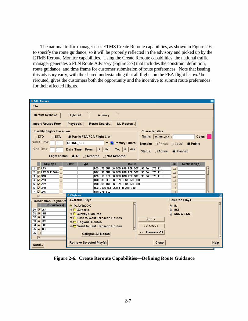
The national traffic manager uses ETMS Create Reroute capabilities, as shown in Figure 2-6, to specify the route guidance, so it will be properly reflected in the advisory and picked up by the ETMS Reroute Monitor capabilities. Using the Create Reroute capabilities, the national traffic manager generates a PLN Route Advisory (Figure 2-7) that includes the constraint definition, route guidance, and time frame for customer submission of route preferences. Note that issuing this advisory early, with the shared understanding that all flights on the FEA flight list will be rerouted, gives the customers both the opportunity and the incentive to submit route preferences for their affected flights.
Figure 2-6. Create Reroute Capabilities—Defining Route Guidance

2-8
Figure 2-7. Create Reroute Capabilities—Generating PLN Route Advisory

2-9
2.2 Generating/Analyzing Reroute Options Customers identify flights affected by the advisory, viewing them on the Reroute Monitor.
Customers have access to the Reroute Monitor on the Common Constraint Situation Display (CCSD), as shown in Figure 2-8 for Northwest Airlines (NWA) flights. The display includes the route guidance applicable to each of their flights.
Figure 2-8. CCSD Reroute Monitor—Identifying Affected Flights with Route Guidance
Customers have the option of submitting preferences for their affected flights. They evaluate and select routes consonant with their business objectives, focusing on whatever factors are important to them. To help them, they can use the route guidance in the advisory, employ the ROG capabilities, and apply their own in-house tools.
If they choose to use ROG capabilities, they can view flight specific information, such as departure/arrival times, route, altitude, speed and aircraft type and the reroute options available for each flight that avoid the FEA. ROG also provides route statistics, such as length, centers traversed, and CDR/Associated Play information, as a reference. Information is provided in a table and the routing information can also be displayed on a map. Filtering criteria allow customers to narrow the list of choices depending on the situation, for example, to exclude certain fixes or sectors that may not be available at a given time. An example of reroute options (table and map) for a NWA flight is shown in Figure 2-9.

2-10
Figure 2-9. ROG Route Selection Capabilities—Analyzing Reroute Options

2-11
2.3 Submitting Customer Preferences via Early Intent Customers submit EI messages to communicate a route preference for flights that do not yet
have a filed flight plan. Some customers may choose to communicate their preference by filing a flight plan avoiding the FEA or refiling for flights with filed flight plans. For example, General Aviation (GA) pilots typically do not (or can not) use EI. However, use of the EI message makes it a little easier for traffic managers to identify the participating flights and thus avoid rerouting them further.
Some customers have the capability to send EI messages directly from their flight planning systems. Others use the EI dialog in CCSD (Figure 2-10). Note that routes selected in ROG can be cut and pasted directly into the CCSD. Since flights that do not avoid the FEA at the end of the EI submission window will be assigned routes by traffic management, customers have an incentive to submit their route preferences within that time period.
Figure 2-10. CCSD Early Intent Dialog—Submitting Preferences
2-12
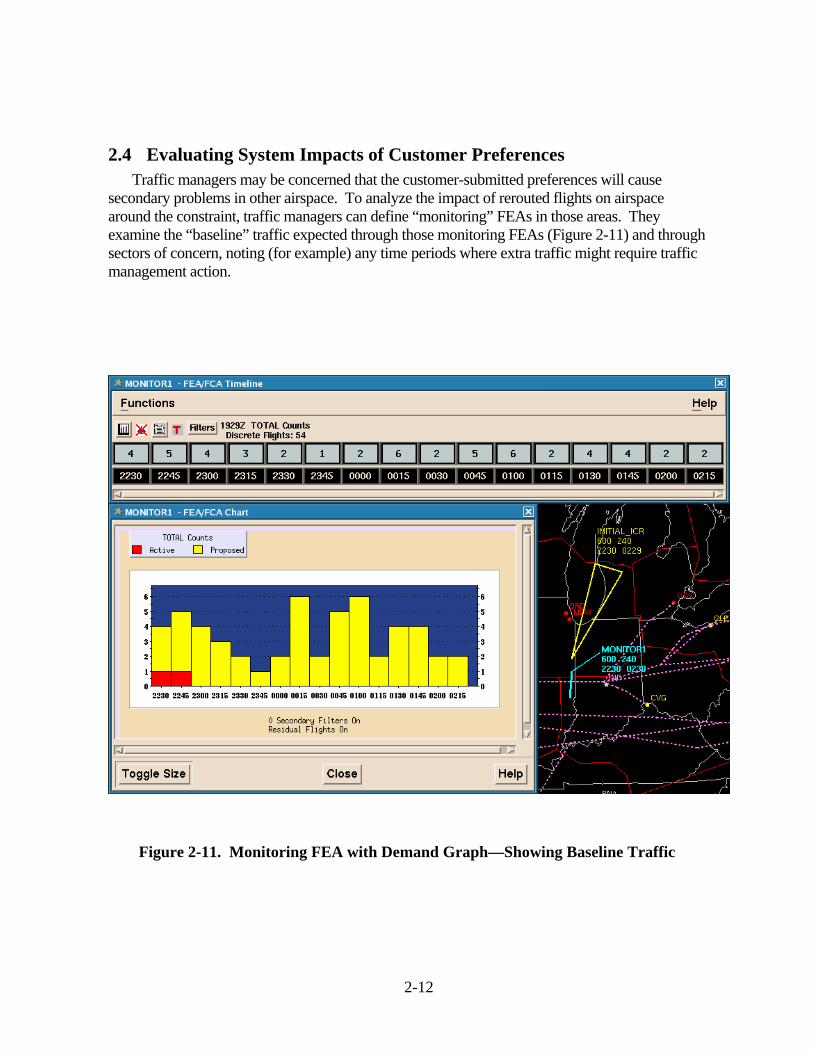
2.4 Evaluating System Impacts of Customer Preferences Traffic managers may be concerned that the customer-submitted preferences will cause
secondary problems in other airspace. To analyze the impact of rerouted flights on airspace around the constraint, traffic managers can define “monitoring” FEAs in those areas. They examine the “baseline” traffic expected through those monitoring FEAs (Figure 2-11) and through sectors of concern, noting (for example) any time periods where extra traffic might require traffic management action.
Figure 2-11. Monitoring FEA with Demand Graph—Showing Baseline Traffic

2-13
As customer preferences are submitted, the traffic managers review those preferences in the Reroute Monitor on the Traffic Situation Display (TSD), as shown in Figure 2-12. When an EI message is submitted for a flight, the EI route replaces the historical route and the prefix “N” is shown on the departure time and in the Flight Status column. Preferences are coded to indicate their conformance with the route guidance. In the Reroute Status (RRSTAT) column, routes that follow the route guidance are labeled Conforming (C), and those that do not are coded as Non-Conforming (NC).
Figure 2-12. Reroute Monitor—Reviewing EI Routes
The local traffic managers examine the non-conforming routes through their airspace to determine the effect of those routes on local flows. If a non-conforming route will cause a local flow problem, the local traffic manager notifies the national traffic manager. The underlying premise is that the customer-submitted preferences will be accepted if at all possible.

2-14
To see the impacts of customer preferences on sector demand, traffic managers analyze sector count and alert data (Figure 2-13), which update automatically as EI messages are received.2. They may also examine the traffic through the monitoring FEAs (Figure 2-14) to note how it has changed from the baseline traffic (shown in Figure 2-11). This information helps the traffic managers decide which routes to assign to those flights that do not avoid the FEA.
Figure 2-13. NAS Monitor and Center Monitor—Analyzing Demand
2 The white numbers over a square black background are counts of the Reduced Vertical Separation
Minima (RVSM) non-conformant flights.

2-15
Figure 2-14. Monitoring FEA with Demand Graph—Showing Impact of EI Routes
When local traffic managers identify local flow problems, they have two options. They may coordinate additional traffic management actions with the national traffic manager, or they may wait and take local action when the flights reach their airspace.
2.5 Implementation and Monitoring When the specified EI submission window expires, traffic managers take action to ensure all
involved flights have assigned routes that take them out of the FEA. During this stage, traffic managers identify the flights that still need reroutes, choose appropriate routes to assign, and issue a RQD Route Advisory with the assigned routes. Customers and traffic managers then implement the reroutes and monitor the results.
This stage of the Initial ICR process takes advantage of some new functionality expected in ETMS 8.3. ETMS 8.2 currently allows the national traffic manager to convert the existing FEA

2-16
to a public FCA and reissue the associated PLN Route Advisory as a RQD Route Advisory with required assigned routes. This results in any flights that no longer have routes through the FCA dropping off the Reroute Monitor list for the advisory and the required assigned routes are not applied to them. The new functionality in ETMS 8.3 will retain flights from the original advisory, so that their status is still shown in Reroute Monitor. This gives traffic managers additional flexibility in assigning routes and lets them better monitor rerouted flights.
The national traffic manager uses other functions, expected in ETMS 8.3, to simplify assigning routes to flights with EI routes:
• For flights with conforming EI routes, their EI routes are automatically assigned to them.
• For flights with non-conforming EI routes that local traffic managers have asked be assigned a different route, but no longer going through the FCA, the route guidance from the PLN Route Advisory is automatically assigned to them.
• For flights with non-conforming EI routes that local traffic managers have not asked be assigned a different route, the national traffic manager uses the Reroute Monitor “OK” feature to assign their EI routes to those flights.
To assign routes to the remaining flights still going through the FCA, the national traffic manager consults with local traffic managers. They may identify routes by using ETMS tools to analyze expected demand and by using the ROG TMI Builder and Assign Reroutes capabilities. Figure 2-15 shows the TMI Builder applied to remaining flights and Figure 2-16 illustrates the use of Assign Reroutes to select a CDR for a flight. The national traffic manager assigns required routes by origin and destination in Create Reroute (Figure 2-17). The assigned routes may be different from the route guidance in the PLN Route Advisory. Traffic managers may add route segments for flights with no applicable pre-coordinated routes.

2-17
Figure 2-15. ROG TMI Builder—Selecting Plays for RQD Route Advisory

2-18
Figure 2-16. ROG Route Selection Capabilities—Finding Flight Specific Reroutes

2-19
Figure 2-17. Create Reroute Capabilities—Assigning Required Routes

2-20
The national traffic manager issues a RQD Route Advisory (Figure 2-18) with the required routes assigned to the remaining flights. Customer preferences that followed the earlier route guidance or were marked “OK” are now considered the assigned routes for those flights. Pop-ups—flights that file through the FCA after the RQD Route Advisory is issued—are automatically assigned the applicable reroute from the advisory.
Figure 2-18. Create Reroute Capabilities—Generating RQD Route Advisory

2-21
Traffic managers and customers observe the assigned routes on the Reroute Monitor (Figure 2-19). For scheduled flights that have not yet filed a flight plan and have not submitted an EI, the historic route is replaced by the assigned route immediately, for use in all ETMS displays, so a better picture of how the reroutes will affect the NAS is available.
Figure 2-19. Reroute Monitor—Showing Assigned Routes
Whether a flight is in compliance with the route assigned to it in the RQD Route Advisory can be easily determined from the Reroute Monitor list, by examining its entry in the Reroute Status column. Flights that submitted EI routes or filed routes that took them out of the FEA before the RQD Route Advisory was issued are still shown on the Reroute Monitor list as being part of this advisory, with the FCA’s name shown in the FEA/FCA Name column.

2-22
As in the current system, the assigned reroutes are implemented by customers filing flight plans with the assigned routes for flights up to 45 minutes3 before their proposed departure time, while traffic managers enter route amendments for filed flights within 45 minutes of departure. Customers may choose to request exceptions for some flights.
As the assigned routes are filed, sector demand patterns are automatically updated to reflect those flights. Local traffic managers monitor the effects of the reroutes and resolve any negative impacts tactically, as necessary.
3 This is the currently agreed-upon lead time, set procedurally rather than in the automation.

3-1
3 Benefits Exercises, conducted by MITRE/CAASD and Metron Aviation, Inc., were held with traffic
managers and customer participants in December 2005 and January 2006. At those HITL exercises, participants provided feedback on the benefits of Initial ICR. Since Initial ICR is the first step in a phased approach, not all benefits of the full concept will be achieved in the initial implementation. Some anticipated benefits of Initial ICR, which need to be further validated and quantified, are as follows:
• Customers are able to submit a preferred reroute for each flight, so those reroutes are more likely to be acceptable when assigned to them. This improves customer buy-in, which should decrease the need for exception requests. It may also increase the number of flights conforming to their assigned reroutes. Potentially, the routes submitted by the customers will be more tailored to the situation, which will result in less delay, and thus cost, for the customers.
• Traffic managers are able to focus more on defining the potential constraint and managing the predicted impacts of the reroutes. Because the customers have an opportunity to provide their own reroutes, the traffic managers spend less time initially picking specific routes to resolve the potential problem. Deciding how to handle flights for which no EI was submitted becomes part of refining the resolution to manage secondary impacts, such as on sectors through which the rerouted flights now fly. This shift in attention from route selection to strategy refinement and impact management should be a more effective use of the traffic managers’ time and expertise.
• Because flights need not be routed along a few easily-specified Playbook corridors, the impact of the reroutes is more diffuse and may be easier to accommodate without additional restrictions, such as miles-in-trail spacing.
• Customers who provided route preferences are more likely to implement those routes themselves, reducing the number of route amendments traffic managers must enter tactically. Each assigned route filed by the customer means potential reductions in verbal coordination between the tower and the center traffic manager, as well as between the clearance delivery position and the pilot.

4-1
4 Next Steps
The next steps for ICR fall into two categories: implementing Initial ICR and refining the next phase of ICR to prepare it for implementation. This section describes the primary tasks within each of these categories.
4.1 Implementing Initial ICR A joint subteam with members from the Flow Evaluation Team (FET) and FCT to oversee the
implementation of Initial ICR was formed and trained in May 2006. They are expected to continue developing procedures for using the capabilities described in this document. Possible activities include conducting additional HITL exercises, running operational tests, and identifying initial candidate situations for the Initial ICR concept.
Another step is to develop training for both automation capability and procedural changes. The joint team plans to work with the appropriate training organizations to identify suitable materials for such training and provide any needed operational expertise.
The joint subteam will also need to address remaining issues as Initial ICR is implemented. In some cases, the issues may be worked out once the initial capabilities and procedures are in place, as their use evolves with experience. In others, implementing later phases of the ICR Concept may address the issue.
1. Do traffic managers have adequate tools and information to determine whether to accept customer preferences that do not follow the route guidance?
2. How much structure is needed in the route guidance for the PLN Route Advisory and are EI routes required to be chosen from those routes?
3. What is the impact of customers filing or refiling flight plans, in response to a PLN Route Advisory that solicits their preferences, instead of submitting Early Intent? How might GA customers be able to participate?
4. Will customers actually use Early Intent to collaborate in Initial ICR, even though submitting route preferences via EI messages is cumbersome and not currently integrated with their internal company processes?
5. Is Initial ICR appropriate for use two to four hours before a constraint is expected to impact traffic?
6. What preferential treatment should be given to flights with EI routes, so they aren’t rerouted again? This is a policy level discussion that needs to be held with both FAA and customer involvement.

4-2
As procedures are developed and issues are resolved, this operational concept for Initial ICR may need to be refined further. Any changes in the Initial ICR concept will be reflected in updates to both this operational concept document and the functional requirements. In addition, more detailed system-level and software requirements can be written by the implementation contractor. For ETMS, this is the Volpe National Transportation Systems Center; for RMT, this is Metron Aviation, Inc.
4.2 Refining the Next Phase of ICR Meanwhile, the FCT expects to continue refining the Full ICR concept and the next step
toward Full ICR, which is ICR Phase 2. As part of refining the operational concept and requirements for ICR Phase 2, it will also be important to understand how the next phase will integrate with the pre-existing evolution plans. In ICR Phase 2, significant enhancements to its operational concept arise from four of its proposed new capabilities: Future Traffic Display with current routes, sharing reroute information among traffic managers before an advisory is sent out, expanding the set of databases available to ROG, and submitting EI messages directly from ROG.
Future Traffic Display (FTD) for current routes shows traffic managers the future positions of traffic, so they can visually check expected flows, as shown in Figure 4-1. Traffic managers can also choose to have FTD graphically display the sector alerts for the time selected. Providing a visual picture of future traffic to traffic managers improves their ability to identify congestion, as well as to fine-tune when and where to apply TMIs.
The second significant capability for ICR Phase 2 allows sharing reroute information among traffic managers before an advisory is sent out. Currently, local traffic managers can only see the routes assigned by the national traffic manager after an advisory is issued, which may result in repeated re-issuing of an advisory as local traffic managers identify routes that cause local flow problems. Sharing the planned reroutes before issuing the advisory, in a similar way to how FCAs can be shared before they are made public, should reducing how often advisories change after being issued. This added stability should benefit both traffic managers and customers.
Incorporating additional pre-coordinated route databases into ROG would significantly enhance the ICR concept as well. For example, frequently used reroutes, preferential routings, e.g., Preferential Departure Routes (PDRs), Preferential Arrival Routes (PARs), Preferential Departure and Arrival Routes (PDARs) and High-Altitude Redesign (HAR) routes would considerably expand the set of ‘good’ or ‘acceptable’ reroute options available quickly to both customers and traffic managers in reroute situations.
Finally, the capability to allow customers to submit EI messages directly from ROG would simplify the process for many customers. That, in turn, may increase customer participation and thus reduce the number of flights left for traffic managers to reroute.

4-3
Figure 4-1. Future Traffic Display Capability—Showing Future Positions of Flights on Their Current Routes

GL-1
Glossary
ATC Air Traffic Control ATCSCC Air Traffic Control System Command Center
C/NC designators for routes that “conform” or “do not conform” to required routes CAASD Center for Advanced Aviation System Development CCSD Common Constraint Situation Display CDM Collaborative Decision Making CDR Coded Departure Route CRI Constraint Resolution Intent
EI Early Intent ETMS Enhanced Traffic Management System
FAA Federal Aviation Administration FCA Flow Constrained Area FCT Future Concepts of Flow Management Sub-Team (formerly the ICE-FM Working Group) FEA Flow Evaluation Area FET Flow Evaluation Team FTD Future Traffic Display
GA General Aviation HAR High Altitude Redesign HITL Human-in-the-Loop
ICE-FM Integrated Concepts for the Evolution of Flow Management (now the FCT) ICR Integrated Collaborative Rerouting
NAS National Airspace System NWA Northwest Airlines PAR Preferential Arrival Routes PDAR Preferential Departure and Arrival Routes PDR Preferential Departure Routes PLN designator for a “Planning” Route Advisory
RMT Route Management Tool ROG Route Options Generation RQD designator for a “Required” Route Advisory

GL-2
RRSTAT designator for the “Reroute Status” column on the Reroute Monitor RVSM Reduced Vertical Separation Minima
TFM Traffic Flow Management TMI Traffic Management Initiative TMU Traffic Management Unit TSD Traffic Situation Display