operational manual oat.2
TRANSCRIPT
8/3/2019 Operational Manual OAT.2
http://slidepdf.com/reader/full/operational-manual-oat2 1/22
TECHNICAL MANUAL
USER‘S AND MAINTENANCE INSTRUCTIONS
RTD CONDITIONER UNIT OAT.2
SPEEL PRAHA, Ltd. BERANOVÝCH 130, PRAHA 9, THE CZECH REPUBLIC
THE INFORMATION CONTAINED IN THIS DOCUMENT IS THE PROPERTY OF SPEEL PRAHA, LTD., AND MAY NOT BEDISCLOSED OR REPRODUCED IN ANYWAY WITHOUT THE WRITTEN CONSENT OF SPEEL PRAHA, LTD.
ALL RIGHTS RESERVED.
©SPEEL PRAHA, Ltd.
2006-11-22

8/3/2019 Operational Manual OAT.2
http://slidepdf.com/reader/full/operational-manual-oat2 2/22
INTENTIONALLY LEFT BLANK
8/3/2019 Operational Manual OAT.2
http://slidepdf.com/reader/full/operational-manual-oat2 3/22
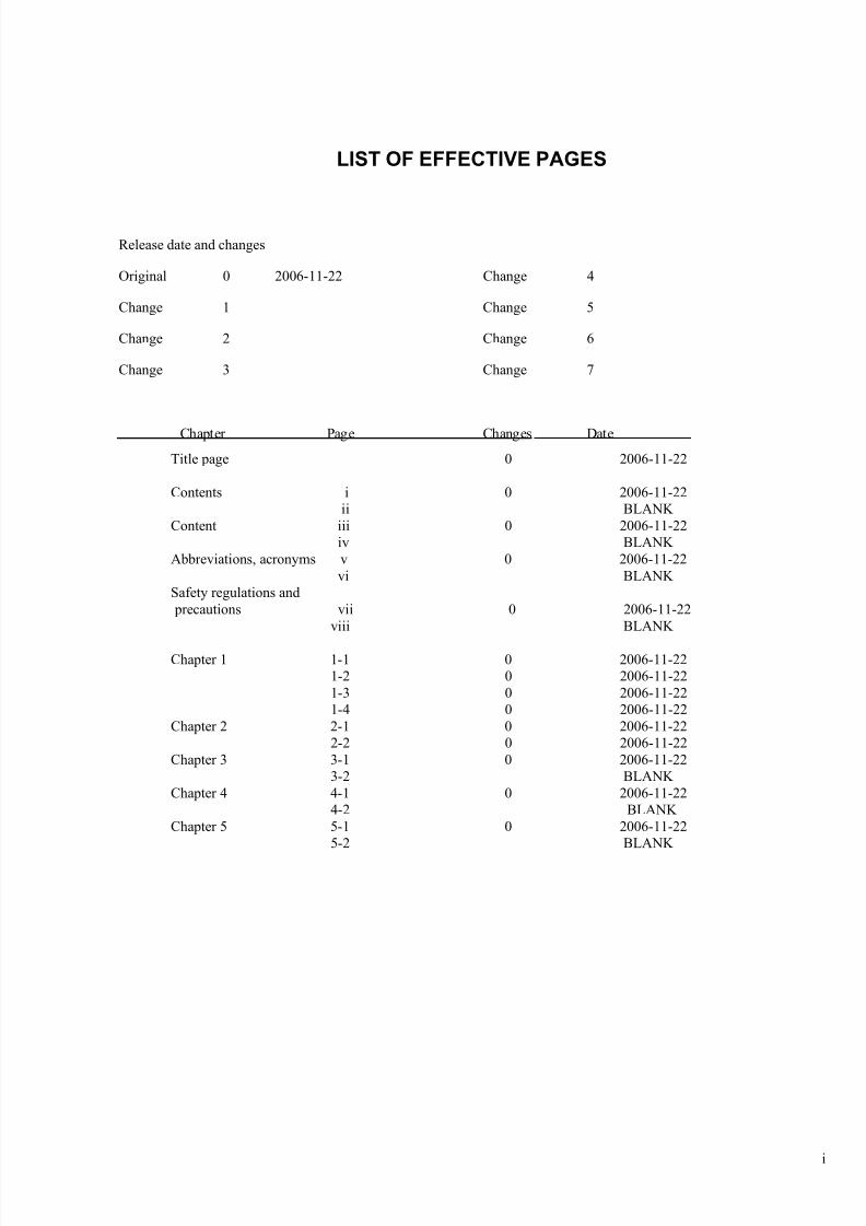
LIST OF EFFECTIVE PAGES
Release date and changes
Original 0 2006-11-22 Change 4
Change 1 Change 5
Change 2 Change 6
Change 3 Change 7
Chapter Page Changes Date
Title page 0 2006-11-22
Contents i 0 2006-11-22ii BLANK
Content iii 0 2006-11-22iv BLANK
Abbreviations, acronyms v 0 2006-11-22vi BLANK
Safety regulations and precautions vii 0 2006-11-22
viii BLANK
Chapter 1 1-1 0 2006-11-221-2 0 2006-11-221-3 0 2006-11-221-4 0 2006-11-22
Chapter 2 2-1 0 2006-11-222-2 0 2006-11-22
Chapter 3 3-1 0 2006-11-223-2 BLANK
Chapter 4 4-1 0 2006-11-224-2 BLANK
Chapter 5 5-1 0 2006-11-225-2 BLANK
i

8/3/2019 Operational Manual OAT.2
http://slidepdf.com/reader/full/operational-manual-oat2 4/22
INTENTIONALLY LEFT BLANK
ii
8/3/2019 Operational Manual OAT.2
http://slidepdf.com/reader/full/operational-manual-oat2 5/22
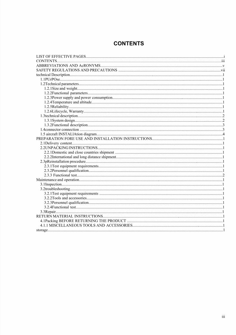
CONTENTS
LIST OF EFFECTIVE PAGES............................................................................................................................................iCONTENTS.......................................................................................................................................................................iiiABBREVIATIONS AND AcRONYMS............................................................................................................................vSAFETY REGULATIONS AND PRECAUTIONS ........................................................................................................viitechnical Description.......................................................................................................................................................... .1
1.1PUrPOse.....................................................................................................................................................................11.2Technical parameters..................................................................................................................................................1
1.2.1Size and weight....................................................................................................................................................11.2.2Functional parameters.........................................................................................................................................11.2.3Power supply and power consumption................................................................................................................11.2.4Temperature and altitude.....................................................................................................................................11.2.5Reliability............................................................................................................................................................11.2.6Lifecycle, Warranty............................................................................................................................................ .1
1.3technical description.................................................................................................................................................. .21.3.1System design..................................................................................................................................................... .21.3.2Functional description.........................................................................................................................................3
1.4connector connection .................................................................................................................................................31.5 aircraft INSTALlAtion diagram................................................................................................................................4
PREPARATION FORE USE AND INSTALLATION INSTRUCTIONS........................................................................12.1Delivery content.........................................................................................................................................................12.2UNPACKING INSTRUCTIONS...............................................................................................................................1
2.2.1Domestic and close countries shipment .............................................................................................................12.2.2International and long distance shipment............................................................................................................1
2.3pReinstallation procedure.......................................................................................................................................... .12.3.1Test equipment requirements..............................................................................................................................12.3.2Personnel qualification........................................................................................................................................1
2.3.3 Functional test....................................................................................................................................................2Maintenance and operation..................................................................................................................................................13.1Inspection...................................................................................................................................................................13.2troubleshooting...........................................................................................................................................................1
3.2.1Test equipment requirements .............................................................................................................................13.2.2Tools and accessories..........................................................................................................................................13.2.3Personnel qualification........................................................................................................................................13.2.4Functional test.....................................................................................................................................................1
3.3Repair.........................................................................................................................................................................1RETURN MATERIAL INSTRUCTIONS..........................................................................................................................1
4.1Packing BEFORE RETURNING THE PRODUCT .................................................................................................14.1.1 MISCELLANEOUS TOOLS AND ACCESSORIES............................................................................................1
storage..................................................................................................................................................................................1
iii

8/3/2019 Operational Manual OAT.2
http://slidepdf.com/reader/full/operational-manual-oat2 6/22
INTENTIONALLY LEFT BLANK
iv

8/3/2019 Operational Manual OAT.2
http://slidepdf.com/reader/full/operational-manual-oat2 7/22
ABBREVIATIONS AND ACRONYMS
BSPI-4 Flight Data Acquisition Unit from BUR-1 system
BUR-1 Flight Data Recording System (used on L410UVP-E aircraft)
OAT Outside Air Temperature
Product RTD Conditioner Unit OAT.2
RTD Resistance Temperature Detector
v

8/3/2019 Operational Manual OAT.2
http://slidepdf.com/reader/full/operational-manual-oat2 8/22
INTENTIONALLY LEFT BLANK
vi

8/3/2019 Operational Manual OAT.2
http://slidepdf.com/reader/full/operational-manual-oat2 9/22
SAFETY REGULATIONS AND PRECAUTIONS
The RTD Condioner Unit OAT.2 contains no element susceptible of threatening health of operating staff and livingenvironment.
vii

8/3/2019 Operational Manual OAT.2
http://slidepdf.com/reader/full/operational-manual-oat2 10/22
INTENTIONALLY LEFT BLANK
viii
8/3/2019 Operational Manual OAT.2
http://slidepdf.com/reader/full/operational-manual-oat2 11/22
CHAPTER 1
TECHNICAL DESCRIPTION
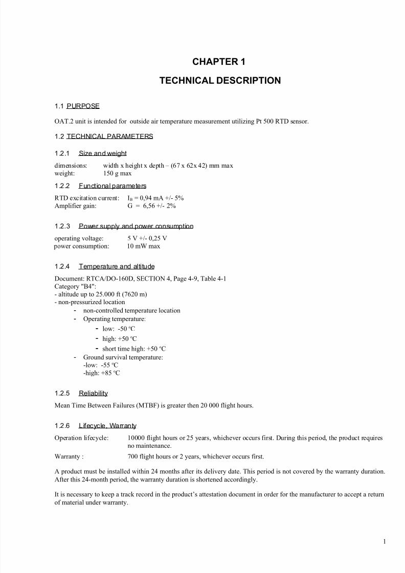
1.1 PURPOSE
OAT.2 unit is intended for outside air temperature measurement utilizing Pt 500 RTD sensor.
1.2 TECHNICAL PARAMETERS
1.2.1 Size and weight
dimensions: width x height x depth – (67 x 62x 42) mm maxweight: 150 g max
1.2.2 Functional parameters
RTD excitation current: IB = 0,94 mA +/- 5%Amplifier gain: G = 6,56 +/- 2%
1.2.3 Power supply and power consumption
operating voltage: 5 V +/- 0,25 V power consumption: 10 mW max
1.2.4 Temperature and altitude
Document: RTCA/DO-160D, SECTION 4, Page 4-9, Table 4-1Category "B4":- altitude up to 25.000 ft (7620 m)
- non-pressurized location- non-controlled temperature location- Operating temperature:
- low: -50 oC
- high: +50 oC
- short time high: +50 oC- Ground survival temperature:
-low: -55 oC-high: +85 oC
1.2.5 Reliability
Mean Time Between Failures (MTBF) is greater then 20 000 flight hours.
1.2.6 Lifecycle, Warranty
Operation lifecycle: 10000 flight hours or 25 years, whichever occurs first. During this period, the product requiresno maintenance.
Warranty : 700 flight hours or 2 years, whichever occurs first.
A product must be installed within 24 months after its delivery date. This period is not covered by the warranty duration.After this 24-month period, the warranty duration is shortened accordingly.
It is necessary to keep a track record in the product’s attestation document in order for the manufacturer to accept a return
of material under warranty.
1
8/3/2019 Operational Manual OAT.2
http://slidepdf.com/reader/full/operational-manual-oat2 12/22
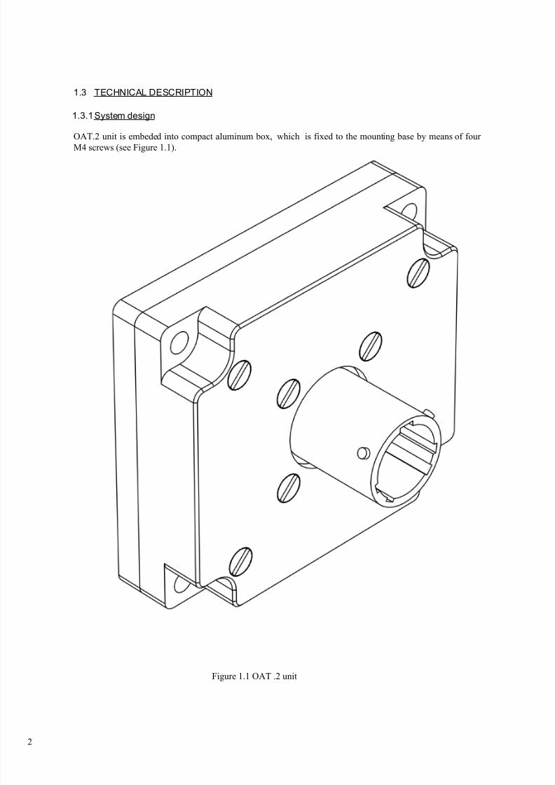
1.3 TECHNICAL DESCRIPTION
1.3.1System design
OAT.2 unit is embeded into compact aluminum box, which is fixed to the mounting base by means of four M4 screws (see Figure 1.1).
Figure 1.1 OAT .2 unit
2
8/3/2019 Operational Manual OAT.2
http://slidepdf.com/reader/full/operational-manual-oat2 13/22
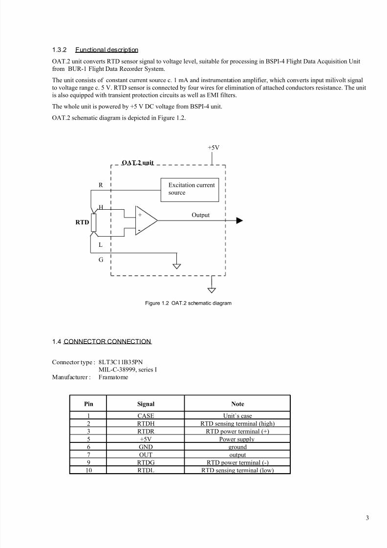
1.3.2 Functional description
OAT.2 unit converts RTD sensor signal to voltage level, suitable for processing in BSPI-4 Flight Data Acquisition Unitfrom BUR-1 Flight Data Recorder System.
The unit consists of constant current source c. 1 mA and instrumentation amplifier, which converts input milivolt signalto voltage range c. 5 V. RTD sensor is connected by four wires for elimination of attached conductors resistance. The unit
is also equipped with transient protection circuits as well as EMI filters.The whole unit is powered by +5 V DC voltage from BSPI-4 unit.
OAT.2 schematic diagram is depicted in Figure 1.2.
+5V
OAT.2 unit
R Excitation current
source
H+ Output
RTD
-
L
G
Figure 1.2 OAT.2 schematic diagram
1.4 CONNECTOR CONNECTION
Connector type : 8LT3C11B35PNMIL-C-38999, series I
Manufacturer : Framatome
Pin Signal Note
1 CASE Unit`s case2 RTDH RTD sensing terminal (high)3 RTDR RTD power terminal (+)5 +5V Power supply6 GND ground7 OUT output9 RTDG RTD power terminal (-)
10 RTDL RTD sensing terminal (low)
3
8/3/2019 Operational Manual OAT.2
http://slidepdf.com/reader/full/operational-manual-oat2 14/22
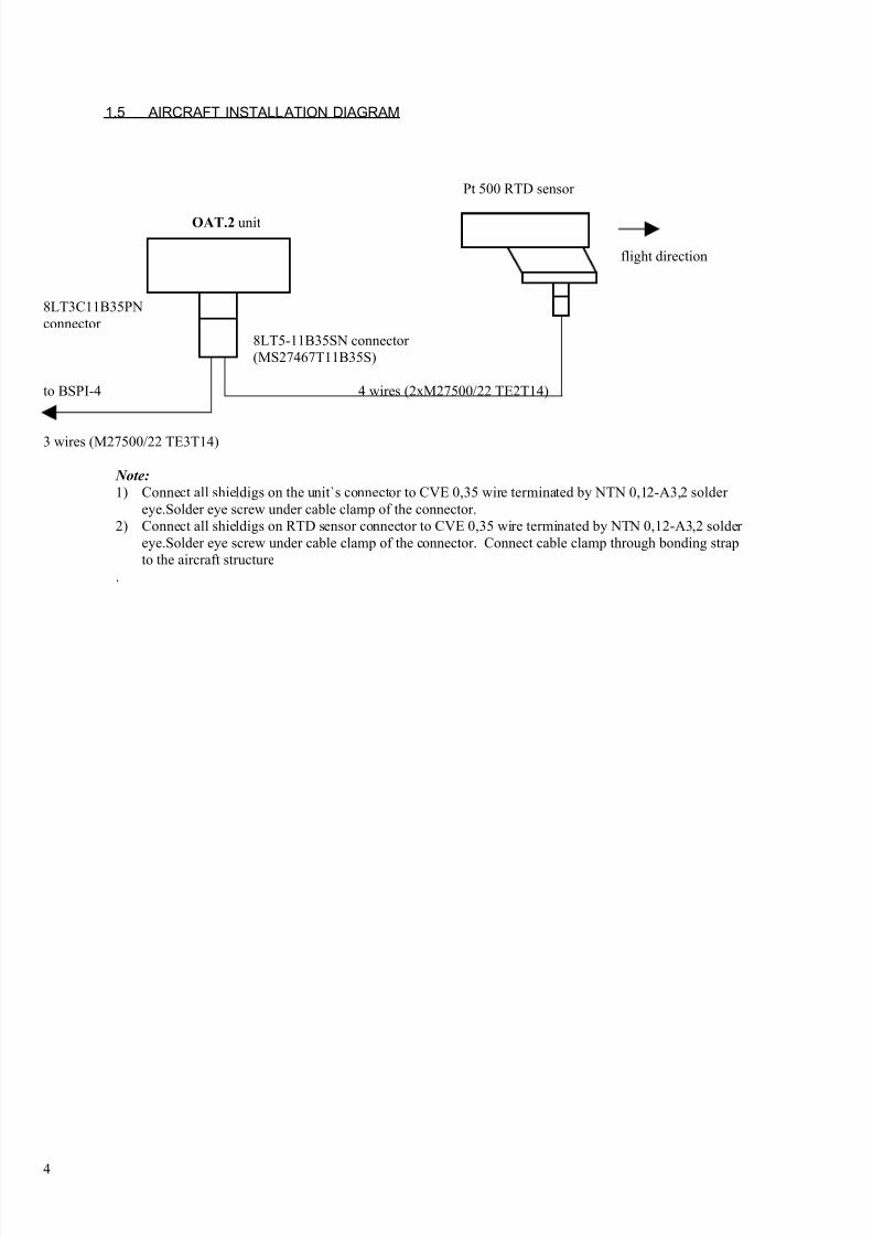
1.5 AIRCRAFT INSTALLATION DIAGRAM
Pt 500 RTD sensor
OAT.2 unit
flight direction
8LT3C11B35PNconnector
8LT5-11B35SN connector (MS27467T11B35S)
to BSPI-4 4 wires (2xM27500/22 TE2T14)
3 wires (M27500/22 TE3T14)
Note:
1) Connect all shieldigs on the unit`s connector to CVE 0,35 wire terminated by NTN 0,12-A3,2 solder eye.Solder eye screw under cable clamp of the connector.
2) Connect all shieldigs on RTD sensor connector to CVE 0,35 wire terminated by NTN 0,12-A3,2 solder eye.Solder eye screw under cable clamp of the connector. Connect cable clamp through bonding strapto the aircraft structure
.
4
8/3/2019 Operational Manual OAT.2
http://slidepdf.com/reader/full/operational-manual-oat2 15/22
CHAPTER 2
PREPARATION FORE USE AND INSTALLATION INSTRUCTIONS
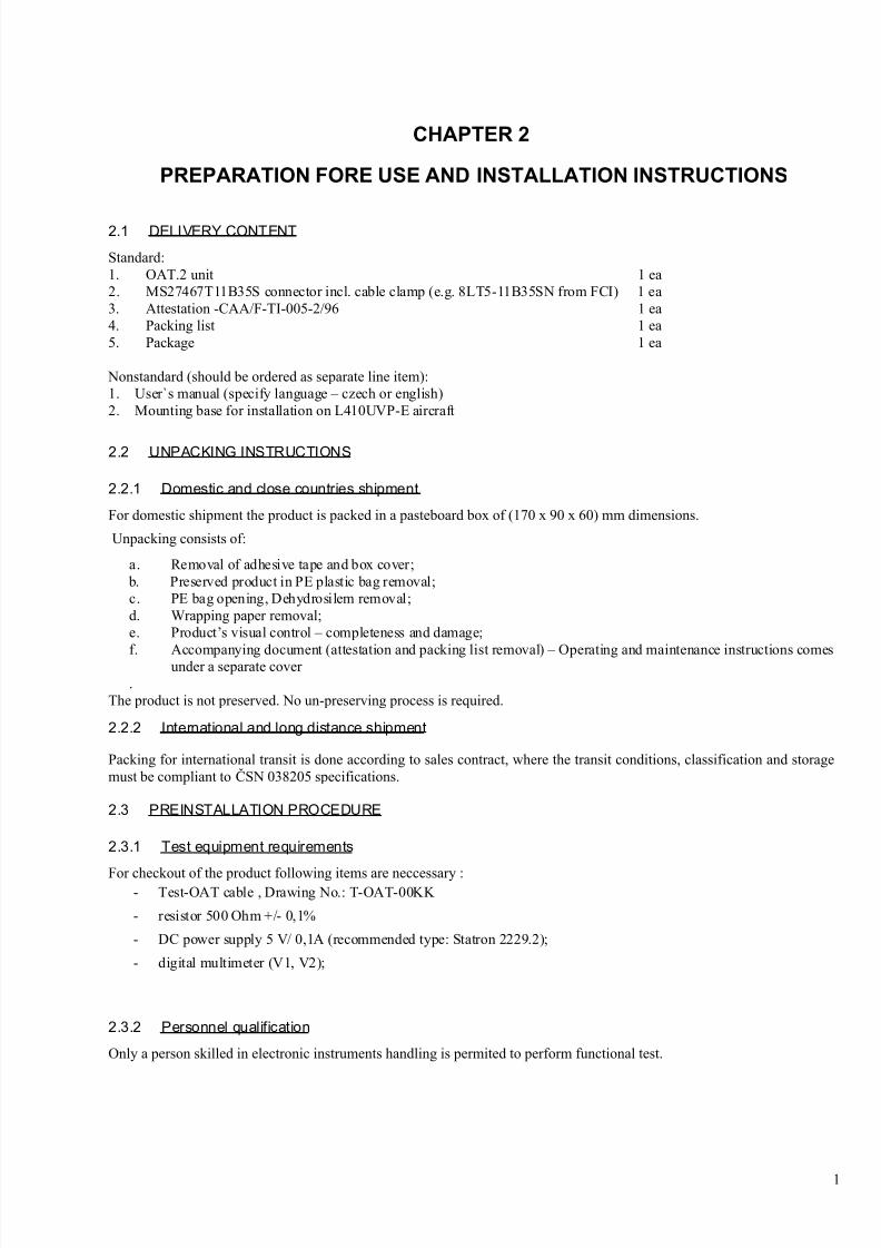
2.1 DELIVERY CONTENT
Standard:1. OAT.2 unit 1 ea2. MS27467T11B35S connector incl. cable clamp (e.g. 8LT5-11B35SN from FCI) 1 ea3. Attestation -CAA/F-TI-005-2/96 1 ea4. Packing list 1 ea5. Package 1 ea
Nonstandard (should be ordered as separate line item):1. User`s manual (specify language – czech or english)2. Mounting base for installation on L410UVP-E aircraft
2.2 UNPACKING INSTRUCTIONS
2.2.1 Domestic and close countries shipment
For domestic shipment the product is packed in a pasteboard box of (170 x 90 x 60) mm dimensions.
Unpacking consists of:
a. Removal of adhesive tape and box cover; b. Preserved product in PE plastic bag removal;c. PE bag opening, Dehydrosilem removal;d. Wrapping paper removal;e. Product’s visual control – completeness and damage;
f. Accompanying document (attestation and packing list removal) – Operating and maintenance instructions comesunder a separate cover .
The product is not preserved. No un-preserving process is required.
2.2.2 International and long distance shipment
Packing for international transit is done according to sales contract, where the transit conditions, classification and storagemust be compliant to ČSN 038205 specifications.
2.3 PREINSTALLATION PROCEDURE
2.3.1 Test equipment requirements
For checkout of the product following items are neccessary :- Test-OAT cable , Drawing No.: T-OAT-00KK
- resistor 500 Ohm +/- 0,1%
- DC power supply 5 V/ 0,1A (recommended type: Statron 2229.2);
- digital multimeter (V1, V2);
2.3.2 Personnel qualification
Only a person skilled in electronic instruments handling is permited to perform functional test.
1
8/3/2019 Operational Manual OAT.2
http://slidepdf.com/reader/full/operational-manual-oat2 16/22
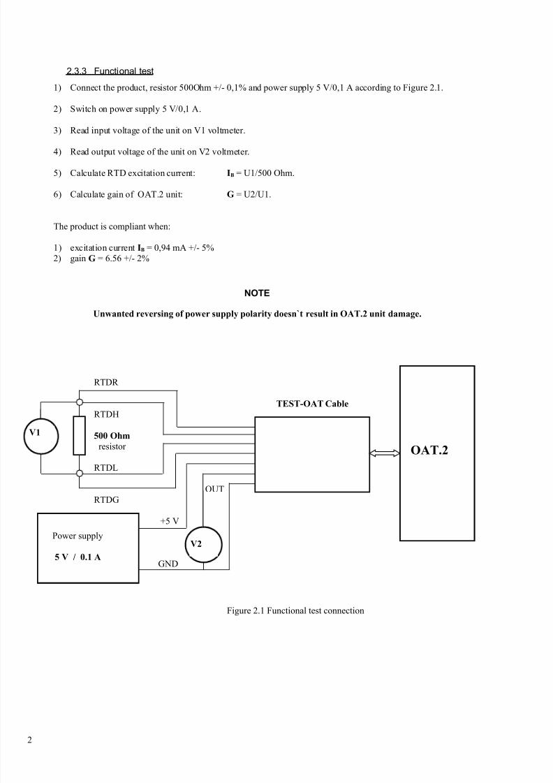
2.3.3 Functional test
1) Connect the product, resistor 500Ohm +/- 0,1% and power supply 5 V/0,1 A according to Figure 2.1.
2) Switch on power supply 5 V/0,1 A.
3) Read input voltage of the unit on V1 voltmeter.
4) Read output voltage of the unit on V2 voltmeter.
5) Calculate RTD excitation current: IB = U1/500 Ohm.
6) Calculate gain of OAT.2 unit: G = U2/U1.
The product is compliant when:
1) excitation current IB = 0,94 mA +/- 5%2) gain G = 6.56 +/- 2%
NOTE
Unwanted reversing of power supply polarity doesn`t result in OAT.2 unit damage.
RTDR
TEST-OAT Cable
RTDH
500 Ohm
resistor
RTDL
OUTRTDG
+5 V
POWER
GND
Figure 2.1 Functional test connection
2
Power supply
5 V / 0.1 A
OAT.2
V1
V2
8/3/2019 Operational Manual OAT.2
http://slidepdf.com/reader/full/operational-manual-oat2 17/22
CHAPTER 3
MAINTENANCE AND OPERATION
3.1 INSPECTION
Procedure consists in visual inspection of the product. Check following items:
- intactness of the product̀ s box;
- intactness of surface protection;
- connector state (intactness of insulator and contacts).
3.2 TROUBLESHOOTING
3.2.1 Test equipment requirements
Equipment for function checking - see item 2.3.1.3.2.2 Tools and accessories
Any specific requirements are not asked.
3.2.3 Personnel qualification
Only a person skilled in electronic instruments handling is permited to perform functional test.
3.2.4 Functional test
Proceed according to instructions in item 2.3.
3.3 REPAIR
Change the whole unit to remove the product failure. Pack the defective unit in accordance with section 4.1 and send it back to the product manufacturer or an accredited service for repair.
1

8/3/2019 Operational Manual OAT.2
http://slidepdf.com/reader/full/operational-manual-oat2 18/22
INTENTIONALLY LEFT BLANK
2
8/3/2019 Operational Manual OAT.2
http://slidepdf.com/reader/full/operational-manual-oat2 19/22
CHAPTER 4
RETURN MATERIAL INSTRUCTIONS
4.1 PACKING BEFORE RETURNING THE PRODUCT
Packing instructions:
a. Don’t use preservation materials. No preservation of the product is required.
b. The product is wrapped using a wrapping paper held together with adhesive tape.
c. Put the wrapped product together with a Dehydrosil bag in a vacuumed PE bag. This operation isn’t necessary incase of short distance transit.
d. Then put the product in pasteboard box and fill up the empty spaces with polystyrene foam. On the top put the product attestation and a return-material report.
Close and girdle the box, append specified marks in accordance with ČSN 770105 norm.
4.1.1 MISCELLANEOUS TOOLS AND ACCESSORIES
1) PE welder
2) Packing paper (300 x220) mm + clips
3) Pasteboard or polystyrene foam
4) Sheet of PE 0,2 mm thick – a bag of 150 x 220 mm size
5) Self adhesive tape (1 m)
6) A bag of Dehydrosil (50 g)
7) Pasteboard box according to item 2.2.1
1

8/3/2019 Operational Manual OAT.2
http://slidepdf.com/reader/full/operational-manual-oat2 20/22
INTENTIONALLY LEFT BLANK
2

8/3/2019 Operational Manual OAT.2
http://slidepdf.com/reader/full/operational-manual-oat2 21/22
CHAPTER 5
STORAGE
The Packed product must be stored in a heated and ventilated space. Storage temperature must remain between -20 and+50°C and 40 to 80 % of humidity.
Sudden temperature fluctuations are not permissible.
The storage room must be hazardous-gas free. Acids, lye or organic solvent materials may not be stored together with the product.
It is recommended to perform a periodical visual inspection of the product once a month during the storage period.
Storage time is 2 years. Storage longer than 2 years requires unpacking of the product and packing it back again inaccordance with chapter 4.
1

8/3/2019 Operational Manual OAT.2
http://slidepdf.com/reader/full/operational-manual-oat2 22/22
INTENTIONALLY LEFT BLANK