operational telecom network for the connected pipeline design … · operational telecom network...
TRANSCRIPT

Operational Telecom Network for the Connected Pipeline System Design GuideLast Updated: July 12, 2016
Building Architectures to Solve Business Problems

Operational Telecom Network for the Connected Pipeline System DGii
About Cisco Validated Design (CVD) Program
The CVD program consists of systems and solutions designed, tested, and documented to facilitate faster, more reli-
able, and more predictable customer deployments. For more information visit http://www.cisco.com/go/designzone.
ALL DESIGNS, SPECIFICATIONS, STATEMENTS, INFORMATION, AND RECOMMENDATIONS (COLLECTIVELY,
"DESIGNS") IN THIS MANUAL ARE PRESENTED "AS IS," WITH ALL FAULTS. CISCO AND ITS SUPPLIERS DIS-
CLAIM ALL WARRANTIES, INCLUDING, WITHOUT LIMITATION, THE WARRANTY OF MERCHANTABILITY, FIT-
NESS FOR A PARTICULAR PURPOSE AND NONINFRINGEMENT OR ARISING FROM A COURSE OF DEALING,
USAGE, OR TRADE PRACTICE. IN NO EVENT SHALL CISCO OR ITS SUPPLIERS BE LIABLE FOR ANY INDIRECT,
SPECIAL, CONSEQUENTIAL, OR INCIDENTAL DAMAGES, INCLUDING, WITHOUT LIMITATION, LOST PROFITS OR
LOSS OR DAMAGE TO DATA ARISING OUT OF THE USE OR INABILITY TO USE THE DESIGNS, EVEN IF CISCO OR
ITS SUPPLIERS HAVE BEEN ADVISED OF THE POSSIBILITY OF SUCH DAMAGES.
THE DESIGNS ARE SUBJECT TO CHANGE WITHOUT NOTICE. USERS ARE SOLELY RESPONSIBLE FOR THEIR
APPLICATION OF THE DESIGNS. THE DESIGNS DO NOT CONSTITUTE THE TECHNICAL OR OTHER PROFES-
SIONAL ADVICE OF CISCO, ITS SUPPLIERS OR PARTNERS. USERS SHOULD CONSULT THEIR OWN TECHNICAL
ADVISORS BEFORE IMPLEMENTING THE DESIGNS. RESULTS MAY VARY DEPENDING ON FACTORS NOT
TESTED BY CISCO.
The Cisco implementation of TCP header compression is an adaptation of a program developed by the University of California,
Berkeley (UCB) as part of UCB’s public domain version of the UNIX operating system. All rights reserved. Copyright © 1981,
Regents of the University of California.
Cisco and the Cisco logo are trademarks or registered trademarks of Cisco and/or its affiliates in the U.S. and other countries. To
view a list of Cisco trademarks, go to this URL: http://www.cisco.com/go/trademarks. Third-party trademarks mentioned are the
property of their respective owners. The use of the word partner does not imply a partnership relationship between Cisco and any
other company. (1110R).
Any Internet Protocol (IP) addresses and phone numbers used in this document are not intended to be actual addresses and phone
numbers. Any examples, command display output, network topology diagrams, and other figures included in the document are
shown for illustrative purposes only. Any use of actual IP addresses or phone numbers in illustrative content is unintentional and
coincidental.
Operational Network Telecom for the Connected Pipeline System Design Guide
© 2015 Cisco Systems, Inc. All rights reserved.

Design Guide
C O N T E N T S
Document Objective and Scope 3
Contributors 4
C H A P T E R 1 Connected Pipeline Overview 1-1
Executive Summary 1-1
The Oil and Gas Value Chain 1-2
Pipeline Management Systems 1-5
Schneider Electric Pipeline Management Solutions 1-5
SCADA System Design Principles 1-6
Availability 1-7
Security 1-8
Integrated Management 1-9
Multiservice Support 1-10
Open Standards 1-11
C H A P T E R 2 Connected Pipeline Architecture 2-1
Control Center Overview 2-2
Operational Communications Network Overview 2-4
Pipeline Stations 2-5
C H A P T E R 3 Pipeline Communication Technology Options 3-1
Layer 2 Ethernet and Layer 3 Transport 3-1
Multiprotocol Label Switching 3-3
MPLS Key Benefits 3-3
Dense Wavelength Division Multiplexing 3-5
DWDM Key Benefits 3-5
Non-Wired Technologies 3-6
Technology Summary 3-7
C H A P T E R 4 Connected Pipeline System Design 4-1
Design Considerations 4-1
Availability Design Principles 4-1
1Operational Telecom Network for the Connected Pipeline System
Contents
Security Design Principles 4-1
Multiservice Design Principles 4-2
Integrated Network Management Design Principles 4-2
Operational Telecoms Design 4-2
Pipeline Station Design 4-3
Controller/RTU Connectivity and Availability 4-4
Station Availability 4-5
Security 4-6
Infrastructure Security 4-6
Multiservice 4-8
Integrated Network Management 4-8
Pipeline Telecom Segments 4-8
Pipeline Telecom Availability: SCADA 4-9
Pipeline Telecom Availability: Multiservice 4-13
Pipeline Telecom Security 4-15
Pipeline QoS 4-16
Integrated Network Management 4-16
MPLS WAN Design 4-17
MPLS WAN Availability 4-17
MPLS WAN Security 4-18
Segmentation 4-18
Service Prioritization: QoS 4-18
Network Management Design 4-20
System Components 4-22
Cisco Products 4-22
Scheider Electric Products 4-22
A P P E N D I X A Acronyms and Initialisms A-1
2Operational Telecom Network for the Connected Pipeline System
Design Guide

Preface
This Operational Telecom Network for the Connected Pipeline System Design Guide documents best practice design of safe, highly available, and secure infrastructure and applications for Oil and Gas pipelines. This Design Guide identifies customer use cases, maps those use cases to relevant architectures, and leverages Cisco and partner technology to deliver unprecedented value for our customers. It:
• Describes a Low Level Design (LLD) detailing a communications architecture for the Connected Pipeline System. It provides guidance supporting SCADA communication principles.
• Documents best practices from real world implementations, detailing the designs and architectures that are mapped back to the customer use cases.
• Addresses real-life customer deployment scenarios by providing a solution that supports implementation of a scalable, secure, and redundant operational network supporting both industrial and multi-service applications.
• Specifies topology, Quality of Service (QoS), high availability, security services, and network management services for the Connected Pipeline communications network.
• Provides information about enforcing cyber security best practices that follow the recognized Industrial Control System (ICS) security standards and guidelines including International Society of Automation 99(ISA99) / International Electrotechnical Commission (IEC) 62443, the National Institute of Standards and Technology (NIST) Cyber Security Framework, and the Purdue Model of Control.
• Documents the suggested equipment and technologies, architecture and technology recommendations. It also includes a description of caveats and considerations that Pipeline operators should understand as they implement best practices.
• Although this Design Guide focuses on midstream transport pipelines, the technologies, use cases, and principles are applicable for gathering and distribution pipelines.
Document Objective and ScopeIn this initial release, Cisco has partnered with Schneider Electric to provide architecture, design, and technologies for the Control Centers, Operational Telecoms Network, and the Pipeline Stations. Cisco provides infrastructure expertise with its unified compute and networking security platforms, while Schneider Electric provides the Pipeline Management System (PMS) leadership with its OASyS DNA SCADA system hardware and software.
3Operational Telecom Network for the Connected Pipeline System
Design Guide

PrefaceContributors
This document will focus on the Control Center and pipeline communications network and security architectures to support pipeline operators. It is recommended that the reader become familiar with the following joint Cisco/Schneider Electric white papers:
• Integrated Enterprise SCADA System Architectures for Safe and Efficient Pipeline Operations at the following URL:
– http://www.cisco.com/c/dam/en/us/solutions/collateral/industry-solutions/dlfe-683318406.pdf
• Converged Telecommunication Architectures for Effective Integrated Pipeline Operations at the following URL:
– http://www.cisco.com/c/dam/en/us/solutions/collateral/industry-solutions/dlfe-683318407.pdf
As with any architecture and design program, functional requirements, use cases, and architectures evolve. Therefore, this Design Guide will evolve and will be updated in future phases.
ContributorsJason Greengrass, Solutions Architect, IoT Vertical Solutions Group, Cisco Systems, Inc.
Rik Irons-McLean, Lead Architect Oil and Gas, IoT Vertical Solutions Group, Cisco Systems, Inc.
4Operational Telecom Network for the Connected Pipeline System
Design Guide

Operational TeDesign Guide
C H A P T E R 1
Connected Pipeline OverviewThis chapter includes the following major topics:
• Executive Summary, page 1-1
• The Oil and Gas Value Chain, page 1-2
• Pipeline Management Systems, page 1-5
• SCADA System Design Principles, page 1-6
Executive Summary This chapter provides a high level overview of the end-to-end Oil and Gas value chain and where pipeline solutions fit into this chain. It also provides an overview of the emergence of virtualization technologies into these environments. This document is written for an industry with a number of key trends:
• Health and Safety—The health and safety of employees continues to be of major importance for organizations. The industry looks to improve overall worker safety while specifically providing a safe working environment for remote or unaccompanied workers.
• Environmental Safety and Compliance—Solutions must meet or exceed industry standards or regulations such as the Pipeline and Hazardous Materials Safety Administration (PHMSA), with increased attention to safety and compliance in regulations a major design factor for telemetry and SCADA systems today.
• An Aging Workforce—Worker age and skill sets have changed. As younger workers with more of an IT-based skill set join the workforce, being able to train and provide remote expertise and consultation to new workers is essential.
• Predictive Automation and Process—Through Big Data, fog or edge compute, and analytics and cloud-based services, sensors are able to provide real-time information on such measures as temperature, vibration, pressure, flow, and current. Combining this with statistical models provides predictive methods for maintenance of equipment and streamlining of processes. The Internet of Things (IoT) has focused on connecting the unconnected through wireless and wired networks, and previously inaccessible data is now available for use.
• Security—As technology evolves, more devices are connected to the network, attackers use increasingly sophisticated methods, and OT and IT technologies begin to converge, protecting assets, people, and intellectual property from cyber and physical threats becomes ever more important.
1-1lecom Network for the Connected Pipeline System

Chapter 1 Connected Pipeline Overview The Oil and Gas Value Chain
It is essential to understand that a single technology cannot enable the industry to meet these requirements. Only a properly architected and secure integration of a number of technologies and applications will keep workers safe, improve efficiencies, reduce cost, and continue to drive innovation.
The Oil and Gas Value ChainAt a high level, the Oil and Gas value chain starts with discovering resources through exploration, and then the development, production, processing, transportation/storage, refining, and marketing/retail of hydrocarbons. This value chain is normally grouped into the upstream, midstream, and downstream areas, as shown in Figure 1-1.
Figure 1-1 Oil and Gas Value Chain
• Upstream—Upstream includes the initial exploration, evaluation and appraisal, development, and production of sites. This is referred to as Exploration and Production (E&P). These activities take place onshore and in the ocean. Upstream includes finding wells, determining how best and how deeply to drill, and determining how to construct and operate wells to achieve the best return on investment.
• Midstream—Midstream primarily includes the transport and storage of hydrocarbons via transmission pipelines, tankers, tank farms, and terminals, providing links between production and processing facilities, and processing and the end customer. Crude oil is transported downstream to the refinery for processing into the final product.
Midstream also includes the processing of natural gas. Although some of the needed processing occurs as field processing near the source, the complete processing of gas takes place at a processing plant or facility, reaching there typically from the gathering pipeline network. For the wholesale markets, natural gas must first be purified by removal of Natural Gas Liquids (NGLs) such as butane, propane, ethane, and pentanes, before being transported via pipeline, or turned into Liquid Natural Gas (LNG) and shipped. The gas can be used real-time or stored. The NGLs will be leveraged downstream for petrochemical or liquid fuels, or turned into final products at the refinery.
• Downstream—Downstream is concerned with the final processing and delivery of product to wholesale, retail, or direct industrial customers. The refinery treats crude oil and NGL and then converts them into consumer and industrial products through separation, conversion, and
Upstream Midstream Downstream Upstream Midstream Downstream
Explore Develop Produce Storage & Transportation Refine Marketing
Marketing Process Transport
Offshore Shipping Trading
Research & Development, Engineering, High Performance Compute
Office Facilities, Call Center, Data Center
Key Oil Gas
37
64
98
1-2Operational Telecom Network for the Connected Pipeline System
Design Guide

Chapter 1 Connected Pipeline Overview The Oil and Gas Value Chain
purification. Modern refinery and petrochemical technology can transform crude materials into thousands of useful products including gasoline, kerosene, diesel, lubricants, coke, and asphalt. Downstream also includes gas distribution pipeline networks.
A visual overview of the value chain is shown in Figure 1-2.
Figure 1-2 Oil and Gas System
Transmission pipelines are the key transport mechanism for the Oil and Gas industry and operate continuously outside of scheduled maintenance windows. Pipelines provide an efficient, safe, and cost-effective way to transport processed or unprocessed oil, gas, and raw materials and products both on- and offshore. It is essential that they operate as safely and efficiently as possible, and, where problems occur, they must be able to rapidly restore normal operation to meet environmental, safety, and quality requirements.
Oil and Gas pipelines (Figure 1-3) comprise operating process, safety, and energy management functions geographically spread along the pipeline for a set of stations. Stations vary in size and function, but typically include large compressor or pump stations, mid-size metering stations, Pipeline Inspection Gauge (PIG) terminal stations, and smaller block valve stations. Each process and application must be linked with the applications and processes at other stations, and at the Control Centers (main and backup) through an operational field telecoms infrastructure. The process must be done in a reliable and efficient way, avoiding communications outages and data losses. The Control Centers should also be securely connected to the enterprise through a WAN to allow users to improve operational processes, streamline business planning, and optimize energy consumption.
1-3Operational Telecom Network for the Connected Pipeline System
Design Guide

Chapter 1 Connected Pipeline Overview The Oil and Gas Value Chain
Figure 1-3 Example Pipeline Station Distribution
Oil and Gas pipeline management is challenging, with pipelines often running over large geographical distances, through harsh environments, and with limited communications and power infrastructure available. In addition, pipelines must comply with stringent environmental regulations and operate as safely as possible, and address growing cyber and physical security threats.
Key pipeline requirements, however, have not changed. Pipeline integrity, safety, security, and reliability are essential elements that help operators meet demanding delivery schedules and optimize operational costs.
At the same time, new operational and multi-service applications are enhancing the way assets and personnel operate. Modern cathodic detection, distributed acoustic leak detection, landslip/earthquake detection, intrusion detection, and physical security applications allow operators to reduce downtime, optimize production, and decrease energy and maintenance costs. Real-time operational data access allows incidents to be identified and addressed quickly, or prevented from occurring in the first place.
Challenges must be addressed through a secure communications strategy to ensure operators can confidently rely on remote data, video, and collaboration solutions for safety and security in addition to operations.
Communications architectures, technologies, solutions, and management for process, energy, security, and multi-service applications (Figure 1-4) must be robust, flexible, and scalable. They should be based on open standards, allowing operations from field device to Control Center, and from Control Center to enterprise, by combining real-time process and business control automation, information management, energy management, and security with global supervision.
37
67
51
1-4Operational Telecom Network for the Connected Pipeline System
Design Guide

Chapter 1 Connected Pipeline Overview Pipeline Management Systems
Figure 1-4 High Level Pipeline Architecture
Pipeline Management SystemsReal-time monitoring and control through sharing and collection of data to a centralized PMS is critical for ensuring that the product is transported safely and efficiently. A PMS combines operational SCADA with real-time applications specific to the oil and gas industry, host-based leak detection, and historical flow measurement.
A well-designed PMS uses a hardware and software architecture that allows functions to be mobile, scalable, flexible, and robust. It also permits distribution of processing among different SCADA system components to optimize overall performance of the PMS.
These integrated applications provide pipeline operators:
• Real-time/near real-time control and supervision of operations along the pipeline through a SCADA system based in one or more Control Centers
• Accurate measurement of flow, volume, and levels to ensure correct product accounting
• Ability to detect and locate pipeline leakage, including time, volumes, and location distances
• Integrated security systems for personnel, the environment, and infrastructure using video surveillance, access control, and Intrusion Detection Systems (IDS)
• Ensured safe operations through instrumentation and safety systems
• Energy management system to visualize, manage, and optimize energy consumption within the main stations.
Schneider Electric Pipeline Management SolutionsSchneider Electric's Enterprise Pipeline Management System (EPLMS) consists of multiple services and applications to facilitate safe and efficient operations, as shown in Figure 1-5.
Pipeline
Main Sta�on (xN) (Compressor /
Pump)
Main Sta�on (xN) (Metering / PIG /
Terminal)
Block Valve Sta�on (xN)
Converged IT and OT Opera�onal Field Telecoms
WAN
Ope
ra�o
nal
Appl
ica�
ons
Mul
�ser
vice
Ap
plic
a�on
s
Ope
ra�o
nal
Appl
ica�
ons
Mul
�ser
vice
Ap
plic
a�on
s
Ope
ra�o
nal
Appl
ica�
ons
Mul
�ser
vice
Ap
plic
a�on
s
Corporate Office / Business Domain
Main Control Center Backup Control Center O
pera
�ona
l Ap
plic
a�on
s
Mul
�ser
vice
Ap
plic
a�on
s
Virt
ualiz
ed
Data
Cen
ter
Ope
ra�o
nal
Appl
ica�
ons
Mul
�ser
vice
Ap
plic
a�on
s
Virt
ualiz
ed
Data
Cen
ter
37
65
00
1-5Operational Telecom Network for the Connected Pipeline System
Design Guide

Chapter 1 Connected Pipeline Overview SCADA System Design Principles
Figure 1-5 Schneider Electrics Pipeline Management Solutions
RealTime SCADA-Schneider Electric's OASyS DNA transcends the traditional SCADA environment by incorporating the workflow needs of customers in real-time. OASyS DNA is an infrastructure product that adapts to the diverse and changing needs of an enterprise. From the field to the enterprise, OASyS DNA allows access to operational and historical data securely at anytime from anywhere.
Oil and Gas Application Suite-Schneider Electric's RealTime Oil and Gas Suite works with the proven Schneider Electric OASyS DNA SCADA system to centralize delivery of key oil and gas pipeline information, enhancing a company's operational environment. Critical data is received for improving pipeline operations and meeting business goals. Schneider Electric offers up-to-the-minute metering and flow totaling; and calculates and monitors line pack, tank storage, hydraulic profiles, and compressor and pump performance in real-time.
• Leak Detection—The main strength of Schneider Electric's SimSuite Pipeline lies in its ability to accurately model the pipeline more completely than other available solutions. The leak-detection application uses a combination of methods to detect and locate leaks. Leaks can occur anywhere on the pipeline; they can vary in size; and they can be caused by fatigue, corrosion, equipment failure, or theft. Large and small leaks can be detected using multiple mass-balance calculations. Pressure-drop calculations can be used to locate the leak.
• Measurement Data—The Schneider Electric Measurement Advisor, empowered with Schneider Electric's advanced measurement user interface, provides the efficient and accurate means to configure devices and collect, validate, modify, and reconcile oil and gas measurement data. Part of the Schneider Electric suite of oil and gas solutions, Schneider Electric Measurement Advisor is the high-mileage solution that gathers measurements for multiple pipelines that interface with various Ethernet in the First Mile (EFM) polling engines, SCADA systems, chart integrators, third-parties, and manual input. Schneider Electric Measurement Advisor allows the precision required at every step to achieve process-wide accuracy.
SCADA System Design PrinciplesThe Connected Pipeline System delivers a forward-looking flexible, modular architecture that enables customers to build the components into an existing system or for a Greenfield deployment. Throughout the architecture, high availability and security are key deliverables. The end-to-end infrastructure provides:
37
65
07
1-6Operational Telecom Network for the Connected Pipeline System
Design Guide

Chapter 1 Connected Pipeline Overview SCADA System Design Principles
• High Availability—Redundancy and reliability mechanisms at the physical, data, and network layer, including robust differentiated QoS and device level redundancy
• Multi-Level Security—Protect against both physical and cyber-attacks, and non-intentional security threats
• Multiservice Support—Operational and non-operational applications co-existing on a communications network, with mechanisms to ensure the right applications operate in the right way at the right time
• Integrated Management—Network, security, and administration management, from the instrumentation or sensor to the Control Center application
• Open Standards—Based on IP, with the ability to transparently integrate and transport traditional or older serial protocols, and ensure interoperability between current and future applications
The jointly architected and validated approach to pipeline management and telecommunications offers many realizable benefits. Solution integration quality and interoperability are maximized, while design and testing time is minimized. End users have a single point of reference (SPR) accountable for integration and operational success from hardware, software, security, and management perspectives throughout a project life cycle. The jointly architected design will provide maximum benefit for current operations, and be a platform for future application enablement and integration.
The key elements of this jointly architected and validated design will be discussed in detail in the following sections.
Availability The system design must encompass a highly available architecture. The pipeline operator must have control of the pipeline 24 hours a day and 365 days of the year. Any loss of visibility or communications will either enforce a shutdown of the process resulting in loss of revenue, or in a worst case scenario, not provide the ability to shut down the pipeline under a catastrophic safety incident such as a major leak.
No SPR should occur on any critical system component of the SCADA system design. A critical component is any component whose failure directly and adversely affects the overall performance of the SCADA system or its ability to continue performing the critical SCADA functions of monitoring and control. The SCADA system uses modular components so that the failure of a single component does not render other components inoperative.
Within this design, redundancy is provided for all critical SCADA functions for monitoring and control. Components comprising the standby capability continuously receive updated data, as appropriate, to provide a hot-standby capability in case of a hardware- or software-initiated failover. As an example, a hot server or critical SCADA application will have a standby equivalent within a Control Center and updates will be passed from this server/application to a backup Control Center if deployed.
The SCADA system connects to the telecommunication networks in such a way that a failure of these networks does not affect the ability of the SCADA system to perform its critical functions for monitoring and control. Redundant network paths, node redundancy, link redundancy, and segmentation of different services are all examples that should be enabled to help maintain the continuous operations of the telecommunication networks. The logic within controllers and the safety systems along the pipeline will still operate if the Control Center loses connectivity to the pipeline stations; however, the ability to control and monitor the pipeline would be lost. Therefore, it is critical that communications to a Control Center are maintained at all times.
1-7Operational Telecom Network for the Connected Pipeline System
Design Guide
Chapter 1 Connected Pipeline Overview SCADA System Design Principles
Security Security, safety, and availability are tightly aligned within an industrial security framework. When discussing industrial network security, customers are concerned with how to keep the environment safe and operational.
Historically, industrial control systems were seen as isolated from the outside world and used proprietary technologies and communications. Security was seen as more of a security-by-obscurity approach. Security outside of physical security wasn't a primary concern. With the modernization of control systems moving towards consumer-off-the-shelf (COTS) products leveraging standardized protocols and connecting to public networks, the process domain now, more than ever, depends on a security framework and architecture. By using more IT-centric products and technologies, and providing connectivity to the enterprise and outside world, new cyber-attacks from both inside and outside the operational environment can potentially occur.
Security incidents can be categorized as either malicious or accidental:
• Malicious acts are deliberate attempts to impact a service or cause malfunction or harm. An example is a disgruntled employee planning to intentionally affect a process by loading a virus onto a server used within the operational control domain or taking control of a process by spoofing a Human Machine Interface (HMI).
• Accidental incidents are probably more prevalent in these environments. Someone may accidentally configure a command incorrectly on a piece of networking equipment, or connect a network cable to an incorrect port. These may be accidental, such as human error, but could be malicious as well, while compromising the safety of people, processes, and the environment.
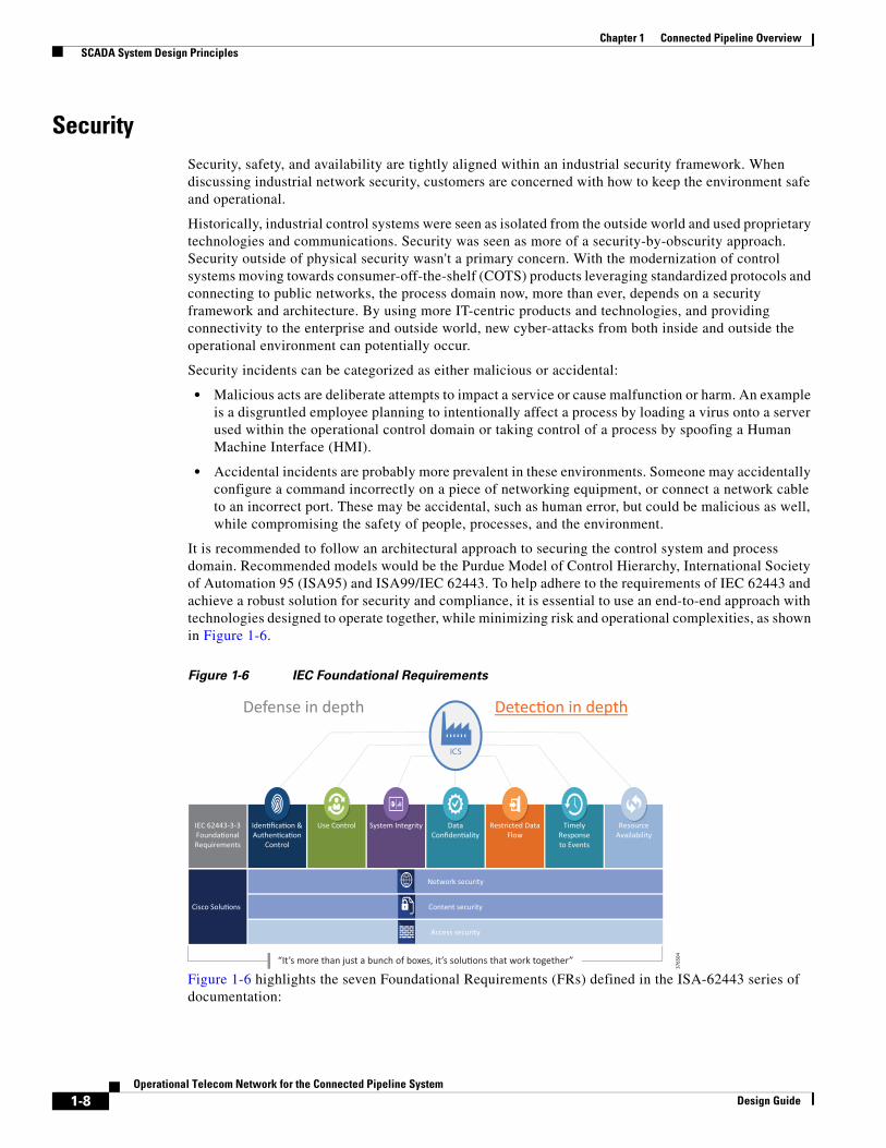
It is recommended to follow an architectural approach to securing the control system and process domain. Recommended models would be the Purdue Model of Control Hierarchy, International Society of Automation 95 (ISA95) and ISA99/IEC 62443. To help adhere to the requirements of IEC 62443 and achieve a robust solution for security and compliance, it is essential to use an end-to-end approach with technologies designed to operate together, while minimizing risk and operational complexities, as shown in Figure 1-6.
Figure 1-6 IEC Foundational Requirements
Figure 1-6 highlights the seven Foundational Requirements (FRs) defined in the ISA-62443 series of documentation:
Defense in depth Detec�on in depth
Data Confiden�ality
Restricted Data Flow
Timely Response to Events
Resource Availability
Iden�fica�on & Authen�ca�on
Control
Use Control System Integrity IEC 62443-3-3 Founda�onal Requirements
ICS
“It’s more than just a bunch of boxes, it’s solu�ons that work together”
Cisco Solu�ons
Network security
Content security
Access security
37
65
04
1-8Operational Telecom Network for the Connected Pipeline System
Design Guide
Chapter 1 Connected Pipeline Overview SCADA System Design Principles
• Identification, Authentication & Control (IAC) (ISA-62443-3-3 FR 1)—Identify and authenticate all users (humans, software processes and devices) before allowing them to access to the control system.
• Use Control (UC) (ISA-62443-3-3 FR 2)—Enforce the assigned privileges of an authenticated user to perform the requested action on the IACS and monitor the use of these privileges.
• System Integrity (SI) (ISA-62443-3-3 FR 3)—Ensure the integrity of the IACS to prevent unauthorized manipulation.
• Data Confidentiality (DC) (ISA-62443-3-3 FR 4)—Ensure the confidentiality of information on communication channels and in data repositories to prevent unauthorized disclosure.
• Restricted Data Flow (RDF) (ISA-62443-3-3 FR 5)—Segment the control system via zones and conduits to limit the unnecessary flow of the data.
• Timely Response to Events (TRE) (ISA-62443-3-3 FR 6)—Respond to security violations by notifying the proper authority, reporting needed evidence of the violation and taking timely corrective action when incidents are discovered.
• Resource Availability (RA) (ISA-62443-3-3 FR 7)—Ensure the availability of the control system against the degradation or denial of essential services.
Defense in Depth is a common term that denotes the multiple layers required to incorporate a security framework. Security isn't just about the technologies to prevent incidents, but also incorporates people, processes, training, and continual assessment. In addition to Defense in Depth, it is also essential to Detect in Depth to ensure malicious activity can be discovered by more than one medium.
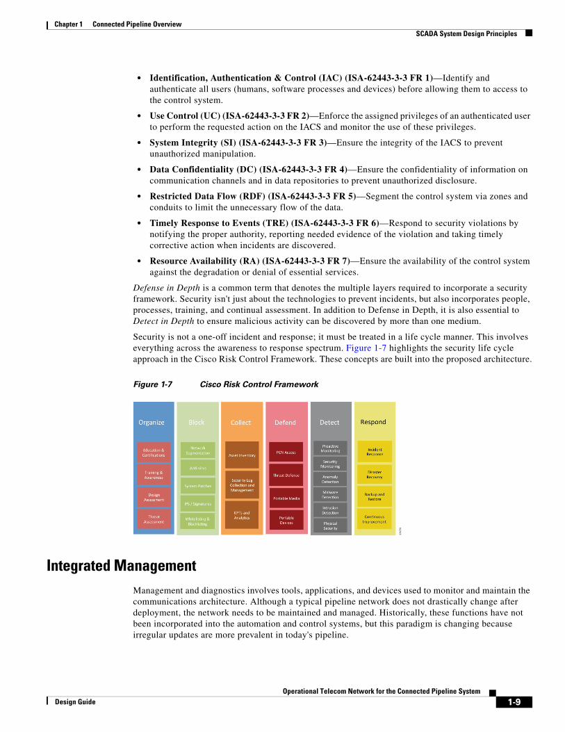
Security is not a one-off incident and response; it must be treated in a life cycle manner. This involves everything across the awareness to response spectrum. Figure 1-7 highlights the security life cycle approach in the Cisco Risk Control Framework. These concepts are built into the proposed architecture.
Figure 1-7 Cisco Risk Control Framework
Integrated Management Management and diagnostics involves tools, applications, and devices used to monitor and maintain the communications architecture. Although a typical pipeline network does not drastically change after deployment, the network needs to be maintained and managed. Historically, these functions have not been incorporated into the automation and control systems, but this paradigm is changing because irregular updates are more prevalent in today's pipeline.
37
67
76
1-9Operational Telecom Network for the Connected Pipeline System
Design Guide

Chapter 1 Connected Pipeline Overview SCADA System Design Principles
Business practices and levels of expertise may dictate the management practice and roles and responsibilities of the system. Companies are merging the boundaries between Information Technology (IT) and Operational Technology (OT) where these have historically remained separate domains. Staff may have differing levels of knowledge to support the applications and infrastructure of the Control Center environment. As an example, if more IT-aware personnel are maintaining the Control Center environment, they must be aware of the business requirements that dictate the security and availability aspects of the operating environment.
Pipeline architectures have differing availability requirements (24 hour per day continuous operations), Service Level Agreements (SLA), and processes compared to the typical enterprise domain. If personnel managing the system are more operationally focused, then it is important to understand the networking technologies and tools used to administer the system. It is therefore critical to establish staff training that hews closely to validated and documented processes so that any misconfiguration incidents are restricted.
The management systems follow the Fault, Configuration, Accounting, Performance and Security (FCAPS) model to help provide and maintain the availability and security of the Control Center architecture. FCAPS management all help to facilitate and monitor the health of the system.
• Fault Management—Detect, isolate, and notify administrators of any issues or faults within the Control Center to help aid with a timely fault resolution.
• Configuration Management—Configure, manage, and maintain the infrastructure and applications for the Control Center. This includes inventory management, software management (upgrades and patch management), configuration management (backups, archiving, and comparisons), and well documented, validated procedures to support change and replacement management.
• Accounting Management—Account management is usually defined for billed networks in order to provide accounting information. Within the context of this system, the A will stand for accounting as it relates to user access and permissions to provide Role-Based Access and Control (RBAC).
• Performance Management—Collect, analyze, and report the application and infrastructure performance of the Control Center and report on any thresholds that may be exceeded.
• Security Management—Manage, monitor, log, and control the security of the infrastructure to identify, defend, and prevent any security threats or breaches.
Integrating the networking management systems into the SCADA operational environments is a key requirement. Operator stations at the Control Center are manned continuously and operators need to be aware of any issues within the networking infrastructure. Alarms and notifications of events should be displayed to the operator.
Multiservice SupportThe architecture provides the ability for both operational and non-operational applications to have convergence over a shared networking infrastructure. The applications, where possible, will have physical separation, although this is not always possible or practical. A key pipeline requirement is the capability to share network resources between critical control traffic and other multiservice traffic, while maintaining strict priority for the critical traffic.
The network must be able to distinguish between the different traffic types in order to provide priority of service in conditions such as when the network is under stress or load. QoS mechanisms must be deployed to classify, mark, and police different traffic types based on business requirements. In the Connected Pipeline architecture, SCADA traffic is prioritized and serviced before any other traffic. This helps to provide predictable performance and ensure that when a packet is sent it will be received within a specific amount of time and with consistent latency and jitter characteristics.
1-10Operational Telecom Network for the Connected Pipeline System
Design Guide

Chapter 1 Connected Pipeline Overview SCADA System Design Principles
Open StandardsA key development in industrial networks is the need to use standardized protocols and infrastructure. Unlike proprietary technologies that may tie companies to a particular vendor, standardized solutions free users to choose the best application for a given solution.
• Multi-vendor Environment—Allows the architecture to select from a wide selection of vendors and provides partnerships where industry leaders can co-operate to provide a total solution.
• Maintainability—Promotes industry standards to simplify the operations and access a less "siloed" workforce to maintain the operations.
• Cost Efficiency—Uses a standard approach to communications, which allows for convergence, better management, and consolidation of resources that help to reduce the total cost of operations (TCO) for the Pipeline System.
• Versatility—Standards promote adoption of new functionality and enhancements that provide gains in performance and availability of the Connected Pipeline architecture.
A key requirement of the Connected Pipeline System is to promote and support standards-based protocols in place of any proprietary-based equivalent. However, under circumstances where a propriety protocol provides enhancements not supported by the standards-based protocol, the architecture shall promote its implementation.
1-11Operational Telecom Network for the Connected Pipeline System
Design Guide

Operational TeDesign Guide
C H A P T E R 2
Connected Pipeline ArchitectureThis chapter, which provides an overview of the Connected Pipeline architecture, includes the following major topics:
• Control Center Overview, page 2-2
• Operational Communications Network Overview, page 2-4
• Pipeline Stations, page 2-5
The architecture is based on a three-tier building block approach as defined in the joint Cisco Schneider Electric reference architecture (see Figure 2-1).
Figure 2-1 Cisco/Schneider Electric Connected Pipeline Reference Architecture
• Control Center—Virtualized, geographically separate, redundant Control Centers
• Operational Telecoms Network—End-to-end communication from field device to Control Center application, for operational and multi-service applications
• Pipeline Stations—Local area networks inside the stations for operational and multiservice applications
L1 Basic
Control
L2 Supervisory
Control
L3 Opera�onal
Control
L3.5 Industrial
DMZ
L4-5 Office & External
Domain
L2.5 Protec�on
IEC62443 ISA99
Horizontal Inter-Zone, Intra-Zone, Inter-System Security
Process Control Power Safety Systems
Compressor / Pump Sta�on
Mul�service
Sta�on WAN, Aggrega�on & Security
Process Domain
Metering / PIG / Terminal Sta�on
Met
erin
g
PIG
Syst
ems
Gas Q
ualit
y
Mul�service Sta�on WAN, Aggrega�on & Security
Process Domain
SCADA & Opera�onal Business Systems
Engineer Worksta�ons
Applica�on Servers
Domain Controller
Instrumenta�on / Sensors Instrumenta�on Instrumenta�on Instrumenta�on
Quantum Quantum
MiCom c264
SIL3 Controller
SIL3 Controller
GTW RI/O GTW RI/O
Historian Operator Sta�on Historian PACIS
Operator Historian Operator Sta�on
Wireless
Mobile Worker
IP Voice
Access Control
CCTV
RFID
Controller Controller Controller
Historian Historian Historian
HMI HMI
SCADA Primary
Leak Detec�on
Physical Security
Operator Worksta�ons
SCADA Backup
Historian Repor�ng
Metering Systems
Main Control Center
Video Opera�ons
Access Opera�ons
Video Storage
Incident Response
Engineering
(virt
uali
-virt
ualiz
ed)
Mul�service Process Domain
Block Valve Sta�on
Quantum
Instrumenta�on
Centralized Opera�ons Office / Business Domain Internet Edge Internet 3rd Party
Support
Voice
Wireless
WLAN Controller
Call Manager
PAGA
Magelis
ION Metering
SEPAM Protec�on
TeSys T Motor Mgt
Al�var Drive
MiCOM Feeder
Protec�on
Magelis
RI/O
ScadaPack
SIL3 Op�on No SIL Op�on
Wireless op�on
Crew Welfare / Infotainment
Decision Support
WAN Networks
Domain Controller
Engineering
Leak Detec�on
Database SCADA
Real-�me
SCADA Historical
Leak Detec�on
Applica�on Test
Real-�me SCADA Zone Development Test
Decision Support
Remote Access
Domain Controllers
(Indu
stria
l DM
Z)
Backup Control Center
Converged Opera�onal Field Telecoms Wireless 3G/LTE, WiMax, 900Mhz RF Mesh, Satellite, Microwave DWDM, Ethernet, IP/MPLS, MPLS-TP
Converged Opera�onal Field Telecoms Wired
Mobile Worker
IP Voice
Access Control
CCTV
RFID
WAN Connec�on & Security WAN Connec�on & Security
Mobile Worker
IP Voice
Access Control
CCTV
RFID
Sta�on WAN, Aggrega�on & Security WAN Connec�on & Security
Phys
ical
Sec
urity
SCAD
A &
Bus
ines
s Sys
tem
s
Voic
e &
PAG
A
Wire
less
Deci
sion
Sup
port
& ID
MZ
37
67
52
2-1lecom Network for the Connected Pipeline System
Chapter 2 Connected Pipeline Architecture Control Center Overview
The Control Center and Pipeline Station (internal process control) architectures are outside the scope of this document, although a high level description of the architecture is included. This document will prioritize the architecture supporting the communications for the SCADA system over the Operational Telecoms Network (OTN).
The Control Center Virtualization for the Connected Pipeline System Design Guide, which provides details of the architecture for the virtualization and operations of the OASyS DNA SCADA software and supporting applications with the Cisco Unified Computing System (UCS), networking, and security platforms, can be found at the following URL:
• https://docs.cisco.com/share/page/site/nextgen-edcs/document-details?nodeRef=workspace://SpacesStore/a23eafa1-6194-45d0-9665-733e2e0de589
The Control Center Virtualization for the Connected Pipeline System Implementation Guide can be found at the following URL:
• https://docs.cisco.com/share/page/site/nextgen-edcs/document-details?nodeRef=workspace://SpacesStore/ae7dc8e5-584c-4b45-9deb-3042e2bc7d57
Control Center OverviewThe SCADA system monitors pressure, flow and temperature amongst other operating data that is communicated back to servers and applications in the Control Center. This data is then displayed to operators where near real time decisions can be made to help the safe transport of the product along the pipeline. A highly available, secure architecture to provide consistent reliable control to the operators is required. Data is not only provided for the operators controlling and operating the pipeline, but is also made available at the Control Centers to the business domain through an IDMZ and secure access.
The Control Center is highly redundant, with redundancy at the application, server, network, and storage components. However, within a Control Center, events that may render a primary Control Center unavailable still exist, communications may be lost with the remote pipeline or a natural disaster may occur that renders a Control Center unavailable to the pipeline stations. A Backup Control Center is implemented to provide for Disaster Recovery events. This Control Center is geographically separate from the Main Control Center. The real-time and historical data stored on the components located at the backup system are kept synchronized with the primary system located in the primary Control Center at all times. If something fails, the backup system is capable of running the entire operations for the pipeline.
The Control Center consists of operational and non-operational domains (Figure 2-2), which are divided into secure zones based on IEC 62443-3-3, Functional Requirement (FR) 5, and Restricted Data Flow. This segments the control system architecturally via zones and conduits to limit the unnecessary flow of data.
2-2Operational Telecom Network for the Connected Pipeline System
Design Guide

Chapter 2 Connected Pipeline Architecture Control Center Overview
Figure 2-2 Control Center Domains
SCADA system environments within the Control Center architecture include operational zones for:
• Production—Domain controllers, real-time, historical and leak detection servers, and operator workstations
• Test—Non-production replica of the operational SCADA system, allowing software and system changes to be validated prior to production without disrupting production
• Development—Development area for reports, displays, and database changes
• Training—Training area built upon the environment that a pipeline controller lives in every day, via a fully functional SCADA control system together with accurate simulation of the pipelines they control
• Decision Support / Industrial DMZ (L3.5):
– Decision support domain controllers, real-time historical. and remote access services
– Isolates the operational system from any external systems or users
– Synchronized with real-time and historical data from the Production system to provide a secure method of providing real-time data to external users
– With firewalls creating a Demilitarized Zone (DMZ), secure services are enabled to provide the external environments exposure to the data
– Functions may include secure FTP connections and long term historians
And non-operational zones for:
• Multiservice—Non-production applications that support the pipeline operation, such as physical security, voice, Public Address and General Alarm (PAGA) safety announcements, video, and wireless
RealTime (Core)ProductionSCADA
PrimarySCADABackup
Decision SupportIDMZ
Training
Test
Decision SupportIDMZ
Training
Non-RealTime (Core)
DevelopmentReplica of Production
Location may vary
Mai
n C
ontr
ol
Cen
tre
Bac
kup
Con
trol
C
entr
e
RealTime (Core)ProductionSCADA
PrimarySCADABackup
Decision SupportIDMZ
MultiservicePhysical Security Voice Services
Emergency Announcements Wireless
Remote Expert Data Access
Ope
ratio
nal D
omai
ns
Non
-Ope
ratio
nal
Dom
ains
37
65
01
2-3Operational Telecom Network for the Connected Pipeline System
Design Guide

Chapter 2 Connected Pipeline Architecture Operational Communications Network Overview
Operational Communications Network OverviewFigure 2-3 shows the operational communications network and where it sits in the end-to-end architecture.
Figure 2-3 Operational Communications Network Architecture
The Operational Telecoms architecture provides a multiservice environment that encompasses:
• Operational services such as SCADA and process applications
• Non-operational services such as CCTV and voice that enable business efficiency and security along the pipeline
The pipeline requires connectivity for communications between Control Centers, between the Control Centers and the pipeline stations, and for any inter-station communication along the pipeline. Availability, security, multiservice support, integrated management, and open standards are the primary requirements for the network as mentioned in Multiservice Design Principles, page 4-2.
Every asset along the pipeline requires high availability of communication. Multiple paths through the network are provisioned to support primary and secondary paths to these assets and ensure continuous operations. Services are segmented (physically or logically) and prioritized so that SCADA networks (operational traffic) and multiservice traffic (non-operational traffic) will not affect each other under normal operations, security incidents, or network congestion. Differentiated services and QoS help to provide prioritization of network resources for the pipeline operational services. Open standards for communication are based on IP, with the ability to transport IP-based SCADA communication protocols, VoIP, and traditional IP-based services, and transparently integrate older serial protocols.
Control
Mul�service
Sta�on WAN, Aggrega�on & Security
Process Domain
Sta�on
Mul�serviceSta�on WAN, Aggrega�on & Security
Process Domain
m Quantum
Com c264
/O GTW
Operator Sta�on
PACIS perator
Operator Sta�on
Wireless
orker
IP Voice
Access Control
CCTV
RFID
Leak Detec�on
SCADA Backup
Mul ervice Process Domain
lock Valve Sta�on
Quantum
Instrumenta�on
Internet 3rd Party Support
Magelis
ON ering
SEPAM Protec�on
TeSys T Motor Mgt
Al�var Drive
ScadaPack
SIL3 Op�on No SIL Op�on
Wireless op�on Crew Welfare /
Infotainment
WAN Networks
Engineering Database SCADA Real-�me
Converged Opera�onal Field Telecoms Wireless 3G/LTE, WiMax, 900Mhz RF Mesh, Satellite, Microwave DWDM, Ethernet, IP/MPLS, MPLS-TP
Converged Opera�onal Field Telecoms Wired
Mobile Worker
IP Voice
Access Control
CCTV
RFID
WAN Connec�on & Security WAN Connec�on & Security
e Worker
Voice
s Control
CCTV
RFID
Sta�on WAN, Aggrega�on & Security WAN Connec�on & Security
Control
Sta�on
m Quanntum
Comc264
/O GTTW
OperratorSta��on
PACCISperrator
OperatorSta�on
Wireelesss
orker
IP Voice
Access CControl
CCTV
RRFFIIDD
lock Valve Sta�on
Quanntum
Instrumenta�on
Magelis
ONering
SEPAMProtec�on
TeSyys TMotoor Mgt
Al��varDrive
ScadaaPack
SIL3 OOp�on No SILL Op�on
Wireelessop��onCrew Welfare /
Infotainment
Mobile Worker
IP Voice
Access CControl
CCTV
RRFFIIDD
e Worker
Voice
s CControl
CCTV
RRFFIIDD
Mul�service ul�service ervice
37
65
10
LeaakDetecc�on
SCADAABacckup
IInnteternrnetet 3rd PartySupport
WANNetworks
Engineee ring Database SCADAAReal-��me
2-4Operational Telecom Network for the Connected Pipeline System
Design Guide

Chapter 2 Connected Pipeline Architecture Pipeline Stations
The communications network can be built using various connectivity options (such as Ethernet, Multiprotocol Label Switching [MPLS], dense wavelength-division multiplexing [DWDM], Optical Transport Network (OTN), cellular, wireless). Factors that influence the communications architecture include power and space availability at the various sites, physical aspects relating to the environment such as ruggedization, no moving parts, extended temperature ranges, capital and operational costs, and the customer's preferred technology. The technology may also be influenced whether the implementation is brownfield or greenfield. The merits and positioning of these technologies will be explained in Chapter 3, “Pipeline Communication Technology Options.”
Pipeline StationsAs detailed earlier, various types of stations will run along the pipeline. A pipeline segment will be bookended with larger stations such as a main terminal or a pumping/compressor station. In between these larger facilities will be intermediate stations, such as metering stations and block valve stations. Regardless of the roles, the stations still have very similar requirements, with environmental or physical factors affecting the architecture within a station. Power may be limited at some of the stations, especially those unmanned and in remote locations such as the block valves. See Figure 2-4.
Station services include:
• Process control for the transportation of oil along the pipeline
• Intelligent power and motor control to manage and control the energy supply at larger stations
• Voice over IP (VoIP) for traditional enterprise voice services and a PAGA system
• Video surveillance as a component of a perimeter security system
Figure 2-4 Pipeline Station Architecture
These services lend themselves to providing a multiservice and operational infrastructure within the station environment. Security and availability are key considerations again at the station level. Segmentation of services, as previously defined, will be built into the architecture. Security policies at
Process Control Power Safety Systems
Compressor / Pump Sta�on
Mul�service
Sta�on WAN, Aggrega�on & Security
Process Domain
Instrumenta�on / Sensors Instrumenta�on Instrumenta�on
Quantum Quantum
MiCom c264
SIL3 Controller
SIL3 Controller
GTW RI/O GTW RI/O
Historian Operator Sta�on Historian PACIS
Operator Historian Operator Sta�on
Wireless
Mobile Worker
IP Voice
Access Control
CCTV
RFID
Magelis
ION Metering
SEPAM Protec�on
TeSys T Motor Mgt
Al�var Drive
MiCOM Feeder
Protec�on
RI/O Crew Welfare / Infotainment
WAN Connec�on & Security
37
65
11
2-5Operational Telecom Network for the Connected Pipeline System
Design Guide

Chapter 2 Connected Pipeline Architecture Pipeline Stations
the network edge will be implemented that protect against unauthorized access, which is particularly important where the stations are unmanned and prevent cross-pollination of traffic between security zones.
QoS classifications, markings, and policies will provide the prioritization of resources for the services at the station and for traffic traversing the operational network to other stations or for Control Center communication.
2-6Operational Telecom Network for the Connected Pipeline System
Design Guide

Operational TeDesign Guide
C H A P T E R 3
Pipeline Communication Technology OptionsIn the past, pipeline technologies were typically direct telephone lines, microwave, cellular, or satellite links. These technologies are now proving inadequate or too expensive for some of the new capabilities that are needed. It is difficult or impossible to provide real-time pipeline condition data, frequent precise flow-measurement data, multiple security video feeds, and multiservice applications, which makes it harder to react to operational incidents, security incidents, or sabotage. At the same time, technology choices are influenced by:
• New operational technologies that better detect and locate problems such as distributed acoustic sensors for leak detection and tamper detection
• Requirements to increase revenue by offering new business services such as service provider functions
• Remote community services such as education and healthcare
Where fiber connectivity is available, deployment options typically include Ethernet, IP, MPLS, and DWDM. Fiber installation also makes it possible to implement newer operational technologies such as distributed optical acoustic sensing for pipeline monitoring, and use additional fiber pairs or wavelengths to provide revenue-generation services through leasing.
For areas where fiber is not available, secure wireless or cellular-based services such as Worldwide Interoperability for Microwave Access (WiMAX), Third-Generation Mobile Network (3G), Long Term Evolution (LTE), and satellite can provide connectivity for the pipeline operations.
Layer 2 Ethernet and Layer 3 TransportEthernet benefits within a LAN architecture are well understood and are now being realized in pipeline deployments. The following benefits and considerations should be considered when deploying Ethernet in the pipeline operational network
• Segmentation—Layer 2 VLANs allow for logical segmentation of operational and non-operational services over the same physical infrastructure.
• Availability—Using technologies such as Resilient Ethernet Protocol (REP) for ring topologies and Flex Links for Star topologies, re-convergence times of 50 ms can be achieved under failure conditions. Layer 3 routing protocols and VPNs provide reachability to the Ethernet segments over a core infrastructure.
• Multiservice—Ethernet supports QoS, allowing operators to converge and prioritize operational above non-operational services over a single infrastructure and meet deterministic requirements.
3-1lecom Network for the Connected Pipeline System
Chapter 3 Pipeline Communication Technology Options Layer 2 Ethernet and Layer 3 Transport
• Scalability—Ethernet is a proven technology with easy scalability options to meet the wide range of bandwidth requirements for a pipeline system, often without a change in onsite equipment. It can readily provide 100 Mb or 1 GB connectivity between stations, and 10 GB connectivity between Control Centers for normal operations or failover scenarios. The availability of standardized services independent of physical access type reduces complexity and cost.
• Management—Simplicity of deployment, configuration, and management makes initial rollouts quicker, and moves, adds, and changes easy.
• Cost-effective—The price per megabit of bandwidth is lower for Ethernet services than for the alternatives. Ongoing operational costs are typically lower for Ethernet, because the knowledge base for this technology is widely available within the industry.
• Standards-based—The industry is standardizing on Ethernet for the process control, energy management, and safety systems. With Ethernet-based services for the WAN, the network architecture is greatly simplified
• Distance—The distance limitation between stations is 80 km maximum for connectivity without additional technologies (DWDM, for example, could be used to extend the reach).
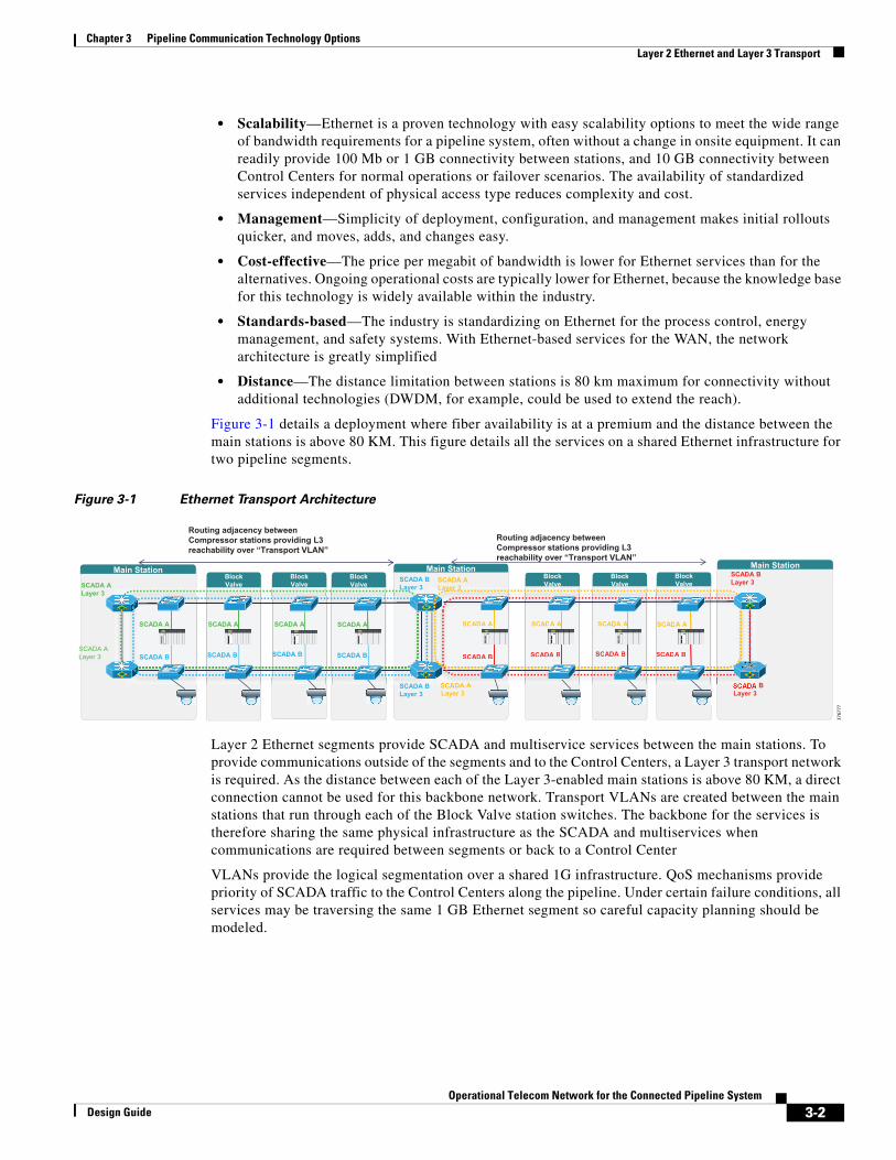
Figure 3-1 details a deployment where fiber availability is at a premium and the distance between the main stations is above 80 KM. This figure details all the services on a shared Ethernet infrastructure for two pipeline segments.
Figure 3-1 Ethernet Transport Architecture
Layer 2 Ethernet segments provide SCADA and multiservice services between the main stations. To provide communications outside of the segments and to the Control Centers, a Layer 3 transport network is required. As the distance between each of the Layer 3-enabled main stations is above 80 KM, a direct connection cannot be used for this backbone network. Transport VLANs are created between the main stations that run through each of the Block Valve station switches. The backbone for the services is therefore sharing the same physical infrastructure as the SCADA and multiservices when communications are required between segments or back to a Control Center
VLANs provide the logical segmentation over a shared 1G infrastructure. QoS mechanisms provide priority of SCADA traffic to the Control Centers along the pipeline. Under certain failure conditions, all services may be traversing the same 1 GB Ethernet segment so careful capacity planning should be modeled.
Main Station
SCADA A
SCADA ALayer 3
SCADA ASCADA ASCADA A
SCADA ALayer 3
SCADA BLayer 3
SCADA BLayer 3
SCADA BSCADA BSCADA BSCADA B
SCADA A SCADA ASCADA ASCADA A
SCADA BLayer 3
BLayer 3
SCADA BSCADA BSCADA BSCADA B
SCADA ALayer 3
DA ALayer 3
Routing adjacency between Compressor stations providing L3reachability over “Transport VLAN”
Routing adjacency between Compressor stations providing L3reachability over “Transport VLAN”
Main StationBlock Valve
Block Valve
Block Valve
Block Valve
Block Valve
Block Valve
Main Station
SCADA A SCADA ASCADA ASCADA A
SSSCADA BSCADA BSCADA BSCADA B
DA A
37
67
77
3-2Operational Telecom Network for the Connected Pipeline System
Design Guide
Chapter 3 Pipeline Communication Technology Options Multiprotocol Label Switching
Multiprotocol Label SwitchingMultiprotocol Label Switching (MPLS) is a technology that uses label switching rather than per-hop routing lookups to forward packets across a network. As the name implies, it has support for multiple protocols including legacy circuit (ATM/TDM) and packet-based (Ethernet) access technologies.
Using the routing information gathered from the Interior Gateway protocol (IGP), a label is created and communicated to connected nodes using the Label Distribution Protocol (LDP). This creates a Label Switched Path (LSP) through a network that allows for the switching of packets rather than per-hop routing lookups.
Originally designed to reduce computational overhead of backbone routers with the switched based characteristics of label switching, MPLS has expanded its capabilities and key benefits including:
• Label stacking within MPLS packets helps to enable VPN services over an MPLS network. VPN labels are stacked behind the core/backbone MPLS labels for transport over a shared infrastructure. The stacking masks the VPN labels from being exposed to the core network and are only seen at the destinations for which they are intended. These VPN labels are exchanged through targeted control plane protocols such as RSVP, Targeted LDP, or BGP.
– MPLS L3VPNs provide an IP-based network delivering private network services over a public or shared infrastructure enabled with MPLS.
– MPLS L2VPNs consolidate Layer 2 traffic such as Ethernet, Frame Relay, ATM, High Level Data Link Control (HDLC), and PPP over an IP/MPLS network.
• Traffic Engineering (TE). With the use of Resource Reservation Protocol (RSVP) to provide label distribution, paths across the network can be engineered to use constraints outside of just the IGP computation as with standard LDP. RSVP-TE tunnels can be created using constraints such as link coloring and bandwidth.
• Multiprotocol Label Switching Transport Profile (MPLS-TP) is a transport-optimized protocol that has a subset of the full IP/MPLS feature set that is defined in the IETF. It is a simplified version of MPLS for transport networks with some of the MPLS functions turned off, offering an evolution architecture for Time Division Multiplexed (TDM)-based transport networks, and is optimized to carry packets.
• Fast Reroute (FRR) mechanisms within MPLS can be leveraged to provide sub-50ms re-convergence through a network. RSVP-TE Fast Reroute (RSVP-TE FRR), Remote Loop Free Fast Reroute (RLFA FRR) are examples.
• Rich Hierarchical QoS (H-QoS) mechanisms with simultaneous support for multiple operational and multiservice applications
For more information, refer to the Introduction to MPLS presentation at the following URL:
• http://www.cisco.com/c/dam/global/fr_ca/training-events/pdfs/Intro_to_mpls.pdf
The following MPLS page provides more advanced topics and enhancements to MPLS:
• http://www.cisco.com/c/en/us/products/ios-nx-os-software/multiprotocol-label-switching-mpls/index.html
MPLS Key BenefitsAligned with the design principles discussed earlier, the following benefits and considerations should be considered when deploying MPLS in the pipeline operational network:
3-3Operational Telecom Network for the Connected Pipeline System
Design Guide

Chapter 3 Pipeline Communication Technology Options Multiprotocol Label Switching
• Segmentation—End-to-end logical proven security options through Layer 2 or Layer 3 VPNs from the Control Center to the pipeline stations provide station-to-Control Center security and isolation. This provides effective use of fiber pairs where logical separation can be employed.
• Availability—Traffic path selection on a per-application basis to provide optimized traffic flow for critical applications. MPLS FRR mechanisms (for network convergence <50 ms), providing fast path-failure recovery, and traffic engineering to provide deterministic application flow across the WAN.
• Multiservice—MPLS supports a flexible QoS, allowing operators to converge and prioritize operational above non-operational services over a single infrastructure and meet deterministic requirements. MPLS can provide support for the transport of legacy TDM services to aid in migration of infrastructures too.
• Scalability—Scalability and ease of deploying new services; scaling to hundreds or thousands of sites supporting multiple operational and multiservice applications, with simple new service introduction. The availability of standardized services independent of physical access type reduces complexity and cost.
• Management—Comprehensive management options, and SLA monitoring for network performance. Skill sets for implementation and ongoing management and administration are increasing, particularly as IT and operational technology (OT) are working together to deliver solutions, and use of service provider training to optimize skill sets.
• Cost-effective—The integration of multiple operational and non-operational applications over a common infrastructure helps to reduce capital expenditures (Capex) and operating expenses (Opex).
• Standards-Based—The industry is standardizing on Ethernet for the process control, energy management, and safety systems. With Ethernet-based services for the WAN, the network architecture is greatly simplified.
• Distance—The distance limitation between stations is 80 km maximum for connectivity without additional technologies (DWDM, for example, could be used to extend reach).
Figure 3-2 is an example of an MPLS-enabled network that will provide reachability between the pipeline segments and the Control Centers.
Figure 3-2 MPLS WAN with Ethernet Rings
MPLS L3VPN services are enabled between the Control Centers and the pipeline main stations over a core MPLS backbone. The L3VPN instances extend the segmentation and separation from the Ethernet segments through the core MPLS network for the SCADA and multiservice applications. LFA-FRR is
Main StationMain Station
Main Station
Block ValveBlock ValveBlock ValveBlock ValveBlock Valve
Main StationMain Station
Main StationMPLS Core
Layer 2 EthernetRings
SCADA LAN A
SCADA LAN B
SCADA LAN A
SCADA LAN B
MultiService MultiService
Main CC Backup CC3
76
77
8
3-4Operational Telecom Network for the Connected Pipeline System
Design Guide

Chapter 3 Pipeline Communication Technology Options Dense Wavelength Division Multiplexing
deployed in the core to provide sub-50ms convergence times. An Ethernet pseudowire through the MPLS network is created to close the Ethernet rings between main stations and protect against failures. The assumption in this model is that fiber availability and distance are limited between main stations to support dedicated direct connectivity between the routers.
Dense Wavelength Division Multiplexing Dense Wavelength Division Multiplexing (DWDM) is an optical transmission technology that transmits signals at different wavelengths over a single fiber optic cable. With amplification and error correction, the transmission capacity can be extended to thousands of KMs. From both an economic and technological perspective, providing potentially unlimited transmission capacity over very long distances is an obvious advantage of an Active Optical Network (AON). Fiber investment can not only be preserved, but it can be optimized by a factor of at least 32 and potentially much more.
DWDM Key BenefitsThe key benefits of DWDM include the following:
• Segmentation: End-to-end proven security options through wavelength/lambda separation for service separation, from Control Center to pipeline station.
• Availability: With extensive network performance analysis options and sub-50 ms path protection, pipeline application can operate reliably. Amplification and error correction capabilities of the active solution provide for a more reliable transmission media over longer distances. Power levels are continuously monitored.
• Multiservice—Has the ability to transparently carry IP, IP/MPLS, and Ethernet technologies, as well as TDM. Can provide per-lambda service separation to provide high capacity, high bandwidth per service.
• Scalability—Scalable high bandwidth to support current and future services.
• Management—Is less operationally complex with a consolidated control plane across the infrastructure. Extensive capacity planning and architecture tools to optimize the network implementation.
• Cost-effective—Can be scaled to provide vast amounts of bandwidth on limited fiber investment. Pipeline operators can provision services rapidly by providing wavelength-on-demand services and leasing for external service providers.
• Long-distance Connectivity—Services can be extended to over hundreds or even thousands of kilometers, meeting the requirements of pipelines where stations are further than 80 km apart, or where services need to be extended point-to-point for specific locations.
• Standards-based—Follows ITU standards.
The following figures provide DWDM in two prevalent deployments. Figure 3-3 represents a pure Lambda service and Figure 3-4 highlights DWDM providing the underlying transport for an MPLS backbone.
The wavelength Lambda service depicted in Figure 3-3 provides a full consolidated control plane. The service provides extended reach, diversity and scalability among any locations. Redundant NCS 2000 DWDM chassis are located at each location with a ring created by passing fiber in a one over one hop scheme along the length of the pipeline. Three protected and isolated 10 GB rings are created for the
3-5Operational Telecom Network for the Connected Pipeline System
Design Guide

Chapter 3 Pipeline Communication Technology Options Non-Wired Technologies
three services at every location. Ethernet services are provided at each location for connectivity to the station equipment and LANs. The fully consolidated control plane provides a very simple and easily manageable system with the capacity to upgrade to vast amounts of bandwidth.
Figure 3-3 Wavelength/Lambda Pipeline
Figure 3-4 depicts a deployment where DWDM provides the extended reach diversity and scalability between any of the core router locations. Wavelength services are configured so that 10 GB services are provided between all core locations creating a fully redundant and resilient core architecture.
Figure 3-4 DWDM Optical Backbone with MPLS Core
Non-Wired TechnologiesSecure wireless or cellular-based services such as WiMAX, 3G, LTE, and satellite are available for brownfield retrofit in areas where fiber is not available, and as backup to wired technologies.
These technologies still allow the transport of Ethernet, IP, and MPLS, but with restricted capabilities because of bandwidth availability. VPN technologies such as Dynamic Multipoint Virtual Private Network (DMVPN) or FlexVPN provide confidentiality and integrity. Converged operational and multiservice application deployments are still possible, but detailed QoS design is essential to ensure operational traffic is given priority in normal operation, particularly if used as backup. High availability designs that use backup hub sites and backup tunnels to keep the communications operational are well documented.
End Station
Block Valve
End Station
Block Valve Block Valve Block Valve Block Valve Block Valve Block Valve
Main Station
Layer 3 for all services
SCADA ASCADA B
SCADAASCADA B
SCADAASCADA B
SCADAASCADA B
SCADA ASCADA B
SCADA ASCADA B
SCADA ASCADA B SCADA
ASCADA B
37
67
79
Main Sta�on
Main Sta�on
Main Sta�on
Block Valve Block Valve Block Valve Block Valve Block Valve
10G MPLS Core
Op�cal Dual Protected Rings
1G Layer 2 Ethernet Rings
SCADA LAN A
SCADA LAN B
SCADA LAN A
SCADA LAN B
Main Sta�onMain Sta�onMain Sta�on
OP
Mul�Service Mul�Service 3
76
78
0
3-6Operational Telecom Network for the Connected Pipeline System
Design Guide

Chapter 3 Pipeline Communication Technology Options Non-Wired Technologies
The deployment of wireless and cellular technologies and wired in the same communications network infrastructure is also possible, and indeed essential in some areas where it is not practical or economically feasible to run fiber. Again, careful consideration of the architecture is needed to maximize performance and ensure correct operation of the pipeline management systems. Figure 3-5 depicts a high level view of a non-wired deployment.
Figure 3-5 Non-Wired Technologies
Technology SummaryThe technology choice implemented will vary for many reasons including customer preference, power and space availability, capital and operational costs, architectural design, and validated testing. Mixed environments are also likely with two or more technology choices used as part of the same design. As an example, DWDM may be implemented in larger pipeline stations where power and cooling are typically not challenges, providing a high-speed, high-bandwidth backbone across the pipeline. In block valve stations, DWDM may not be deployed because of power and space constraints, so Ethernet rings between main stations may be deployed. Whichever technology is implemented, the foundational architecture is essential for ensuring ease of implementation and operation of the communication networks and the pipeline management systems.
Figure 3-5 provides an overview of the various technologies that may contribute to a pipeline communications architecture with key requirements. The following legend describes the colored circles in the figure:
• Green—Meets the requirements shown in column headings
• Amber—Meets requirements, but limitations exist
• Red—Does not meet requirements
Block Valve
BlocValve
Block Valve
Main
Terminal
Main
Terminal
Block Valve
Main
Terminal
MCC BCC
Primary : 3G, LTE Satellite,
Backup : 3G, LTE Satellite
37
67
81
3-7Operational Telecom Network for the Connected Pipeline System
Design Guide

Chapter 3 Pipeline Communication Technology Options Non-Wired Technologies
Figure 3-6 Pipeline Communications Architecture Technology Overview
N/A
Technology Bandwidth Latency Distance Reliability<50ms Re-
convergenceQoS
Skillsets for
Deploy/Operate
Multiservice
Support
Ethernet
MPLS
DWDM
3G
LTE
Satellite
WiMax
37
65
33
3-8Operational Telecom Network for the Connected Pipeline System
Design Guide
Operational TeDesign Guide
C H A P T E R 4
Connected Pipeline System DesignThis chapter includes the following major topics:
• Design Considerations, page 4-1
• Operational Telecoms Design, page 4-2
Design Considerations
Availability Design PrinciplesDesign principles for availability include the following:
• Make pipelines operational 24 hours a day and year round. A robust, highly available communications network is essential to support the control and operations of the pipeline.
• Promote redundancy at all aspects of the architecture. Dual SCADA networks are suggested to provide added resiliency to the pipeline network.
• Make fiber pairs within the same physical failure domain such as a single conduit regardless of how many exist. The ability to recover from dual fiber cuts is a common requirement that needs to be addressed.
• Enable QoS throughout the architecture to prioritize operational communications above all other traffic.
• Heavily tie security and safety to availability. If the network is compromised, this could affect pipeline communications between the Control Center and the pipeline stations.
Security Design PrinciplesDesign principles for security include the following:
• In a pipeline architecture, the ability to securely restrict and isolate services to protect the integrity of the traffic is paramount. Intentional or accidental cross-pollination of traffic between untrusted entities must be restricted
• The architecture will promote path isolation techniques, both physical and logical, to promote a dedicated infrastructure per service.
• At routed boundaries, firewalls and ACLs should be implemented to prevent cross-pollination of traffic between services and to provide isolation.
4-1lecom Network for the Connected Pipeline System

Chapter 4 Connected Pipeline System Design Operational Telecoms Design
• At shared infrastructure points, apply QoS techniques to restrict non-essential traffic and prioritize operational communications when appropriate.
• With logical association of firewalls, VLANs, L3VPN instances, and physically separated interfaces of equipment and security policies, a perimeter can be defined adhering to requirements of IEC 62443.
• Provide an auditable trail of security events.
Multiservice Design PrinciplesDesign principles for multiservice include the following:
• A QoS-enabled network to provide prioritization of SCADA traffic above all other services
• Physically segment (where possible) multiservice traffic from the SCADA and process traffic to preserve isolation of services across the infrastructure
• Virtual segmentation techniques where physical segmentation is not possible
Integrated Network Management Design PrinciplesDesign principles for integrated network management include the following:
• Use secure methods to provide extra security for network management traffic. SSH and SNMP v3 are examples.
• Enable personnel to monitor and maintain the network infrastructure as they do with the other automation and control equipment in order to optimize the entire pipeline operation.
• Provide visibility of events, faults and performance of the network to the operators in the Control Center.
• Enable RBAC for access to the infrastructure components.
Operational Telecoms DesignThis document focuses on the design considerations and guidelines for a pipeline network with an MPLS core for connectivity between main stations and the Control Center, and Layer 2 Ethernet rings between the main stations. As we aim to minimize some of the potential complexity of newer designs as technology develops, this is the design that has been validated.
4-2Operational Telecom Network for the Connected Pipeline System
Design Guide

Chapter 4 Connected Pipeline System Design Operational Telecoms Design
Figure 4-1 Operational Telecoms Network
The Operational Telecoms Network provides connectivity between the primary/backup Control Centers and between the Control Centers and the Pipeline Main Stations. The Operational Telecoms Network, which is shown in Figure 4-1, can be broken into three fundamental areas:
• Core MPLS Network—The WAN design for the Connected Pipeline will use an MPLS backbone supporting L3VPN services from the pipeline main stations to the Control Centers and for communications between the Control Centers. The SCADA networks and multiservice networks will have reachability through separate L3VPN instances, promoting segmentation and availability.
• Pipeline Telecom—Optical fiber will be deployed along the segment of the pipeline. Layer 2 Ethernet rings will run the length of the pipeline segment using VLANs and physically separate optical fibers to promote segmentation. Two SCADA RTU LAN rings will be deployed to promote availability of the SCADA communications. From a networking perspective, Layer 2 networks for the SCADA services and multiservices will be Layer 3 terminated at the main stations and inserted into separate L3VPN instances for transport over the core MPLS network. Firewalls act as the Layer 3 gateways providing access and policy to the SCADA RTU networking segments from the WAN and between adjacent interconnecting pipeline segments.
• Station Network—Each station network will have SCADA availability promoted with a connection from a single RTU or redundant RTUs to each of the two SCADA RTU LANS (RTU LAN A and RTU LAN B).
Pipeline Station DesignFor the purpose of this release of the design, the main station and block valve station have the same coverage. The primary focus is on the SCADA/RTU communication and does not delve into the full station design. Power management network IEC61850 and the process control network seen in Figure 4-2 in the main station are outside the scope of this release.
Core MPLS Network• L3VPN Service between the CC and pipeline• Customer owned
B/ValveMain Station Main Station
Active/StandbyASA Active/Standby
ASA
RTU LAN A RTU LAN B Multiservice
B/Valve B/Valve B/Valve
WAN to Control Center
EoMPLS PW’s per Service
Main CC Backup CCMCC/BCC L3VPN
ASR 903Dual RP
ASR 903Dual RP
Station Network• Station RTU’s Dual connected to each
SCADA network
Pipeline Telecom• Optical fiber along the pipeline• L2 Ethernet rings between Main stations• Dual SCADA networks• Separate Multiservice Ring• L2.5 Routed firewalls to enforce security at
protected subnets
37
67
82
4-3Operational Telecom Network for the Connected Pipeline System
Design Guide

Chapter 4 Connected Pipeline System Design Operational Telecoms Design
Figure 4-2 Main Station and Block Valve Station Architecture
Controller/RTU Connectivity and Availability
Figure 4-3 depicts a key component to the dual SCADA network design. A single RTU with dual networking interfaces allows connectivity to two separate networks. Each RTU interface connects to a different VLAN/Layer 2 domain. For example, in Figure 4-3:
• RTU A LAN—VLAN 10 192.168.1.0/24
• RTU B LAN—VLAN 20 192.168.2.0/24
The RTU can be configured so that both ports can be used to communicate with the Control Centers. This provides availability to two separately addressable interfaces over two separate networks.
Figure 4-3 Controller/RTU Connectivity
Within a brownfield deployment where an older controller model may be deployed, a single connected controller can utilize the same concept by using a gateway to provide serial to Ethernet conversion. The controller will have connectivity through two different Ethernet networks. Figure 4-4 shows the single Ethernet controller/RTU connectivity.
RTU Dual Connected
RTU LAN A
RTU LAN B
Mul� Service
Mul� Service
Video Server
Access Control
Energy Mgmt61850 Sta�on Bus
ASR
ASA
Cisco Industrial Switches
SCADA RTU
ISA 3000
Main Sta�on
Block Valve
Cisco Industrial Switches
829 Backup 3G/LTE/SAT
SCADA VPN A SCADA VPN B
Energy Mul�service
RTU A LAN/RING
RTU B LAN/RING
Address from RTU A VLAN
Address from RTU B VLAN
37
67
83
RTU A LAN/RING
RTU B LAN/RING
Address from SCADA A VLAN
Address from SCADA B VLAN
37
67
58
4-4Operational Telecom Network for the Connected Pipeline System
Design Guide

Chapter 4 Connected Pipeline System Design Operational Telecoms Design
Figure 4-4 Single Ethernet Controller/RTU Connectivity
Station Availability
Within the station environment, each service will have its own dedicated physical switch and Ethernet segment. Figure 4-5 highlights the basic architecture for the Block Valve station and the Main stations. Two RTU LANs and one multiservice LAN exist, all with dedicated switching and infrastructure. If for any reason dedicated switch and infrastructure cannot be provided to help promote availability and security of the services, then logical segmentation utilizing VLANS over a shared infrastructure is an alternative.
Figure 4-5 Station Architecture Overview
The following are the design recommendations:
• Each service has its own VLAN and dedicated physical switch.
• Enabling REP on the switches promotes Layer 2 redundancy through the pipeline segments. (The REP design is explained in Pipeline Telecom Segments, page 4-8.)
• Single RTU with dual networking interfaces connected to two different SCADA RTU VLANs on two separate switches.
RTU A LAN/RING
RTU B LAN/RING
Address from RTU A VLAN
Address from RTU B VLAN
Gateway Serial/Ethernet
37
67
84
RTU Dual Connected
RTU LAN A
RTU LAN B
Mul� Service
Mul� Service
Video Server
Access Control
Energy Mgmt61850 Sta�on Bus
ASR
ASA
Cisco Industrial Switches
SCADA RTU
ISA 3000
Main Sta�on
Block Valve
Cisco Industrial Switches
829 Backup 3G/LTE/SAT
SCADA VPN A SCADA VPN B
Energy Mul�service
RTU A LAN/RING
RTU B LAN/RING
Address from RTU A VLAN
Address from RTU B VLAN
37
67
85
4-5Operational Telecom Network for the Connected Pipeline System
Design Guide

Chapter 4 Connected Pipeline System Design Operational Telecoms Design
• Both RTU ports will be active and seen by the Control Center, although one maybe preferred in a primary secondary role.
Security
Firewalls are deployed at the main stations in the architecture. Within the Purdue model of control, this is not formally called, but is typically referred to as, a Layer 2.5 firewall. It sits between the operational domain of the level 3 and the process control domain levels of Level 2 and below. Within this architecture, the firewalls provide the following functions:
• Used for station protection for high availability, inter-zone security (process control, safety system, energy).
• They provide inter-zone security protecting the SCADA RTU LANs.
• A policy and security point between pipeline segments is provided. This can be used for inter-pipeline security.
All Layer 3 routing and policy is applied at the main stations. The ASA redundant firewalls positioned in the main stations provide protection of traffic from the WAN and the multiservice network. The Block Valves only have Layer 2 Ethernet services configured. Segmentation and isolation of the services are provided using VLANs and physical segmentation of each of the services. The firewalls at the main stations will allow communications between SCADA Control Center t and the RTU and vice versa.
Infrastructure Security
Simple but effective infrastructure security measures should be implemented within this phase on the Industrial Ethernet switches. This is especially important for unmanned stations such as block valves.
To provide extra levels of security, basic infrastructure mechanisms exist to help protect the switching infrastructure. The following sections describe guidelines that should be followed.
Shutdown Unused Ports
Place any ports not being used into a shutdown state. For the purpose of a switch, add the switchport VLAN command with an unused VLAN (not VLAN 1) so that if a port is accidentally activated it won't affect any deployed VLANs.
Trunk Ports
The following best practices should be configured to prevent such attacks as VLAN hopping.
When configuring trunk ports, turn DTP off and explicitly configure trunking on the infrastructure ports. Use a dedicated VLAN ID on all trunk ports. Do not use VLAN 1 for anything and configure all tagged mode for the native VLAN on trunks. Only add the VLANs that are required on the trunk ports.
DHCP Snooping
If servers or workstations in the architecture are using DHCP, then DHCP snooping and Dynamic ARP Inspection (DAI) should be considered.
DHCP snooping is a security feature that acts like a firewall between untrusted hosts and trusted DHCP servers. The DHCP snooping feature performs the following activities:
• Validates DHCP messages received from untrusted sources and filters out invalid messages
• Rate-limits DHCP traffic from trusted and untrusted sources
4-6Operational Telecom Network for the Connected Pipeline System
Design Guide

Chapter 4 Connected Pipeline System Design Operational Telecoms Design
• Builds and maintains the DHCP snooping binding database, which contains information about untrusted hosts with leased IP addresses
• Uses the DHCP snooping binding database to validate subsequent requests from untrusted hosts
Other security features, such as DAI, also use information stored in the DHCP snooping binding database.
Dynamic ARP Inspection
DAI is a security feature that validates ARP packets in a network. DAI intercepts, logs, and discards ARP packets with invalid IP-to-MAC address bindings. This capability protects the network from some man-in-the-middle attacks.
For guidance and configuration for this feature, please see “Configuring Dynamic ARP Inspection” in the Cisco IE 2000 Software Configuration Guide, Release 15.0(2)EA at the following URL:
http://www.cisco.com/c/en/us/td/docs/switches/lan/cisco_ie2000/software/release/15_0_2_ea/configuration/guide/scg-ie2000/swdynarp.html
Port Security
Port security limits the amount of MACs on a particular interface. This helps to prevent threats such as MAC attacks. Port security should be enabled on access ports. Port security can be used with dynamically learned and static MAC addresses to restrict a port's ingress traffic by limiting the MAC addresses that are allowed to send traffic into the port. When you assign secure MAC addresses to a secure port, the port does not forward ingress traffic that has source addresses outside the group of defined addresses.
For guidance and configuration for this feature, please see “Configuring Port-Based Traffic Control” in the Cisco IE 2000 Software Configuration Guide, Release 15.0(2)EA at the following URL:
• http://www.cisco.com/c/en/us/td/docs/switches/lan/cisco_ie2000/software/release/15_0_2_ea/configuration/guide/scg-ie2000/swtrafc.html
Traffic Storm Control
A traffic storm occurs when packets flood the LAN, creating excessive traffic and degrading network performance. You can use the traffic storm control feature to prevent disruptions on Ethernet interfaces by a broadcast, multicast, or unknown unicast traffic storm.
For guidance and configuration for this feature, please see “Configuring Port-Based Traffic Control” in the Cisco IE 2000 Software Configuration Guide, Release 15.0(2)EA at the following URL:
• http://www.cisco.com/c/en/us/td/docs/switches/lan/cisco_ie2000/software/release/15_0_2_ea/configuration/guide/scg-ie2000/swtrafc.html
Infrastructure Management
Most of the networking management protocols that are used are insecure (such as SNMP, Telnet, and FTP). Use the secure variants of these protocols (SSH in place of Telnet, SNMP V3).
Use out-of-band (OOB) management to manage the infrastructure the preferred method is to run the management infrastructure separately from the main Control Center infrastructure. If this is not possible, use a dedicated VLAN for management.
Protect the user access and privilege levels of all the networking devices. Authentication, Authorization and Accounting (AAA) should be enabled. The preferred method would be to use a TACACS+.
4-7Operational Telecom Network for the Connected Pipeline System
Design Guide

Chapter 4 Connected Pipeline System Design Operational Telecoms Design
Each of these features enhances the infrastructure security at the access. Implementation of Sourcefire IPS/IDS, dot1x, SGT, to help identify anomalies, provide identification, and implement enhanced policies are all technologies that can be deployed within the station environment, although are not included within this specific release. The goal of this release is to provide simple but effective security practices at the station level.
Multiservice
As detailed in Station Availability, page 4-5, dedicated infrastructure exists for each of the RTU LANs and for multiservices. QoS is enabled at switches to provide classification and marking of all traffic types. Although each Ethernet segment has a dedicated infrastructure, points exist in the network where these traffic types will converge and prioritization of operational traffic (SCADA) above non-operational (multiservice) traffic is a requirement. The same consideration would be required on a shared infrastructure where logical segmentation is deployed using VLANS to isolate the traffic. Other traffic on each of the dedicated Ethernet segments such as network management (SSH, Syslog, and SNMP), security updates for the RTUs or controllers should also be considered and operational traffic must be prioritized above these. Finally, visibility into the various traffic types traversing the end-to-end infrastructure can be provided in classifying and marking the traffic at the edge.
A more detailed description of QoS is provided in MPLS WAN Design, page 4-17.
Integrated Network Management
The pipeline operator needs to have visibility into the performance and health of the network that provides the communications for the pipeline management system. The network management system needs to provide visibility such that the infrastructure alarms, events, and networking statistics are made visible to the operator and acted upon.
Each station should use the following guidelines. Further details are provided later in the document in Network Management Design, page 4-20.
• OOB Management should be used where possible; dedicated VLANs should be used if in band management is used.
• QoS should be configured to classify and mark the management traffic at the access points to the network (switches in the stations). This will allow for SCADA traffic to be prioritized above the network management traffic throughout the architecture.
• Use secure methods to provide extra security for network management traffic. SSH and SNMP v3 are examples.
• Provide visibility of events, faults, and performance of the network to the operators in the control center using Syslog and SNMP.
• Enable RBAC for access to the infrastructure components.
Pipeline Telecom SegmentsFigure 4-6 provides an overview of the validated implementation. Alternatives to the validated design will be explained where appropriate in the subsections. The concept of a SCADA RTU/Controller having access to two separately addressed networks is key to understanding the design.
4-8Operational Telecom Network for the Connected Pipeline System
Design Guide

Chapter 4 Connected Pipeline System Design Operational Telecoms Design
Figure 4-6 Connected Pipeline Validated Design
Three Layer 2 Ethernet segments exist in the design. Two of the networks are designated for access to the RTU. These are RTU LAN A and RTU LAN B. The other network is designated for the non-operational services such as voice and video to promote segmentation and isolation of critical and non-critical services. This is the multiservice LAN. Each of the Ethernet segments is deployed in a 1 GB Ethernet Ring topology. The Ethernet rings in the figure will be "closed" using an Ethernet over MPLS Pseudowire (EoMPLS PW) between the main stations and will be terminated at Layer 3 in the main stations.
Pipeline Telecom Availability: SCADA
Fiber pairs may be multiple but still within the same physical failure domain. The ability to recover from dual fiber cuts is a common requirement that needs to be addressed within a pipeline communications design. The technology and design for availability addresses this key design principle.
Figure 4-7 depicts the design for a singular pipeline segment. The design allows for connecting multiple segments along the length of the pipeline.
Figure 4-7 Single Pipeline Segment
Main StationMain Station
Main Station
Block ValveBlock ValveBlock ValveBlock ValveBlock Valve
Main StationMain Station
Main Station
MPLS Co
1G Layer Ethernet R
SCADA LAN A
SCADA LAN B
SCADA LAN A
SCADA LAN B
MultiService MultiService
Main CC Backup CC
37
67
86
B/Valve Main Sta�on Main Sta�on
Ac�ve/Standby ASA
Ac�ve/Standby ASA A
ASR 903 Dual RP
ASR 903 Dual RP
RTU LAN A RTU LAN B Mul� Service
B/Valve B/Valve B/Valve
EoMPLS PW’s per Service
REP Alternate Port (Blocking)
RTU LAN A RTU LAN B
MPLS WANMPLS WAN3
76
78
7
4-9Operational Telecom Network for the Connected Pipeline System
Design Guide

Chapter 4 Connected Pipeline System Design Operational Telecoms Design
A single Cisco Aggregation Services Router 903 (Cisco ASR 903) router deployed at each main station has full redundancy enabled. The router has dual power supplies and dual route processors, and the physical connection of networks/services should be spread across the Ethernet modules. The dual SCADA rings are Layer 3 terminated at different main stations. RTU LAN A is terminated at the left main station on the pipeline segment and RTU LAN B is terminated at the right main station. This promotes dual SCADA redundancy at different physical places in the network. If, for example, the router in the left main station fails, the RTUs in the stations will still have connectivity to the control centers through the right main station on the alternate RTU LAN Ethernet segment.
Ethernet Ring Design Options
Two models have been validated for providing connectivity for Layer 2 Ethernet Segments along the pipeline. The deployment decision will depend on fiber availability, lengths between interconnecting stations, and technology preference.
Option 1: EoMPLS Pseudowire Ring Closure
Figure 4-8 highlights the design using an EoMPLS PW. The EoMPLS PW will extend the Layer 2 domain between the main stations to close the rings. These Ethernet circuits will only be used during failure conditions within the physical ring. This design is used when optical distance is limited between stations and can be used in designs where less fiber may be available and services are deployed over a shared infrastructure.
Figure 4-8 EoMPLS Pseudowire Ring Closure
Option 2: One-over-One Station Hopping
If the distance between main stations allows for the design and adequate fiber is available, then a one-over-one hopping scheme, as depicted in Figure 4-9, is an alternative to the EoMPLS Pseudowire ring design. The design connects between switches on the same Ethernet segment at alternate stations. The only caveat to this design is in the case of a multiple fiber cut. No communications will occur between stations either side of the break. With the EoMPLS design, station-to-station communication either side of the break would flow through the EoMPLS PW.
B/Valve Main Sta�on Main Sta�on
Ac�ve/Standby ASA
Ac�ve/Standby ASA A
ASR 903 Dual RP
ASR 903 Dual RP
RTU LAN A RTU LAN B Mul� Service
B/Valve B/Valve B/Valve
MPLS WAN
EoMPLS PW’s per Service
REP Alternate Port (Blocking)
MMPPLLSS WWAANN
37
67
88
4-10Operational Telecom Network for the Connected Pipeline System
Design Guide

Chapter 4 Connected Pipeline System Design Operational Telecoms Design
Figure 4-9 One-over-One Station Hopping Ring Architecture
Resilient Ethernet Protocol
Resilient Ethernet Protocol (REP) is a Cisco technology that provides an alternative to STP. REP provides a way to control network loops, handle link failures, and improve convergence time in the range of 50 -200 ms. It controls a group of ports connected in a segment, ensures that the segment does not create any bridging loops, and responds to link failures within the segment.
The Resilient Ethernet Protocol Overview can be found at the following URL:
• http://www.cisco.com/c/en/us/support/docs/lan-switching/ethernet/116384-technote-rep-00.html
EoMPLS REP Design Consideration
REP alternate ports will be configured so that traffic will only use the EoMPLS in failure scenarios. As the left-hand station is advertising the SCADA A network, all communications for devices connected on this ring will utilize the left main station between the pipeline and the Control Center. In this instance, the REP alternate port is provisioned on the ASR at the opposing station. Figure 4-10 describes this design and highlights the flow of traffic between a pipeline block valve station and the Main Control Center.
B/Valve Main Sta�on Main Sta�on
Ac�ve/Standby ASA
Ac�ve/Standby ASA A
ASR 903 Dual RP
ASR 903 Dual RP
RTU LAN A RTU LAN B Mul� Service
B/Valve B/Valve B/Valve
MPLS WAN
EoMPLS PW’s Service REP Alternate Port (Blocking)
MMPPLLSS WWAANN
37
67
89
4-11Operational Telecom Network for the Connected Pipeline System
Design Guide

Chapter 4 Connected Pipeline System Design Operational Telecoms Design
Figure 4-10 REP Alternate Port Placement EoMPLS Ring Design
After restoration of the failure scenario in normal configuration, the location of the alternate port will remain at the point of the failure. Preemption should be configured so that the alternate port will return to the location at the opposing ASR router. This will incur an extra convergence event on restoration, but will ensure that the EoMPLS circuit will only be used under failure conditions.
In the one-over-one station hopping scheme, the REP alternate port is placed at the midpoint in the ring to optimize path diversity for Control Center-to-RTU communications and restrict the number of switches the traffic must traverse.
Figure 4-11 REP Alternate Port Placement One-Over-One Design
Understanding that in a pipeline architecture, physical and environmental aspects may influence technology implementation, the REP switch segments should generally be built up to 16 switches. Although REP supports larger ring topologies, restricting ring sizes to 16 switches helps to keep failure
B/Valve 1 Main Sta�on Main Sta�on
RTU LAN A RTU LAN B Mul� Service
B/Valve B/Valve B/Valve
EoMPLS PW’s per Service
Main CC
RTU LAN A RTU LAN B
REP Alternate Port
Inter RTU
SCADA CC – RTU LAN A
SCADA CC – RTU LAN B
MPLS WAN
37
67
90
B/Valve Main Sta�on Main Sta�on
Ac�ve/Standby ASA
Ac�ve/Standby ASA A
ASR 903 Dual RP
ASR 903 Dual RP
RTU LAN A RTU LAN B Mul� Service
B/Valve B/Valve B/Valve
MPLS WAN
EoMPLS PW’s Service REP Alternate Port (Blocking)
Main CC
MMPPLLSS WWAANN
37
67
91
4-12Operational Telecom Network for the Connected Pipeline System
Design Guide

Chapter 4 Connected Pipeline System Design Operational Telecoms Design
domains smaller in size. Under failure conditions, all traffic could traverse the same switch path within the ring. Bandwidth availability should be considered and is another reason to keep the ring reduced in size where possible.
Layer 3 Availability
The previous sections have discussed design guidance for Layer 2 networking along the pipeline. The ASAs will be the Layer 3 gateway for each instance of the SCADA networks at each main station. This enforces policy, isolation, and prevents cross-pollination of traffic at a routed boundary. A redundant pair of firewalls will exist at each station in an active/standby configuration. RTU LAN A will have dedicated firewalls providing routing awareness and availability at the left-hand station. The same setup will be provided for RTU LAN B on the right-hand station. See Figure 4-12.
Figure 4-12 Pipeline Telecom Availability
Routing is enabled between the ASA and the VRF instance on the ASR router. L3VPN services provide the routing awareness between the Control Center and the pipeline RTU LAN segments. Although not really Layer 3 availability mechanisms, port channel provides increased availability between the firewalls and the routers.
Pipeline Telecom Availability: Multiservice
From a connectivity standpoint, the multiservice equipment does not have the same capabilities as a SCADA controller or RTU, which can be deployed with dual Ethernet interfaces. A video surveillance camera or VoIP Phone, in most instances, has a single interface to connect to the Ethernet network. The multiservice end point will not be dual attached or have primary backup capabilities as do the RTU LANs. Segmentation and isolation from the critical SCADA communication networks of the RTU LANS is critical, either through physical or virtual means. Further isolation of the non-operational services, such as separating voice networks from video networks, is recommended.
Main Sta�on
• Ac�ve/Standby ASA • L3 gateway RTU LAN A configured at this ASA • Port channel redundancy • Prevent Mul�service Traffic impac�ng SCADA traffic
(RTU LAN) with ACL at the ASR and policy on the ASA
ACL applied to restrict Mul�service hi�ng RTU VLAN
37
67
93
4-13Operational Telecom Network for the Connected Pipeline System
Design Guide

Chapter 4 Connected Pipeline System Design Operational Telecoms Design
Figure 4-13 Multiservice Availability
Figure 4-13 highlights key concepts that drive the design in the EoMPLS PW for multiservice applications. The endpoints are not dual attached as seen in the figure. Therefore, a decision needs to be made about the redundancy model required for this service. If redundancy is required to be split across the main stations over a single network to survive a station failure, then the following recommendations should be followed:
Layer 3 Availability
• The Layer 3 gateway will be configured on the ASRs for the multiservice rings.
• Virtual Router Redundancy Protocol (VRRP) will run between the two ASRs for the multiservice VLAN to provide Layer 3 gateway redundancy.
• Reachability to the multiservice networks from the Control Center will be through L3VPNs configured from both main stations to the primary and backup Control Centers.
The VRRP active router should be configured to influence inbound routing into the VRRP active router. This reduces the possibility of using the EoMPLS tunnel in non-fault conditions.
Layer 2 Availability
• The multiservices' rings will be running REP.
• The multiservice ring will be closed using an EoMPLS pseudowire between the ASRs over the MPLS network.
• The alternate port will be configured on the non-VRRP active ASR so that all traffic traversing the ring will utilize the physical ring under normal operation. This will limit the use of the EoMPLS PW unless there is a break in the ring. In the figure above, the left hand station is the active VRRP router.
The multiservice rings would not have policy applied at the ASAs in this architecture. Running active/standby firewalls between main stations over a pseudowire is not supported. Therefore, the Layer 3 policy point or gateway is at the ASR routers. ACLs applied at the ASR provide security policy for the multiservice Ethernet segment.
Multiservice Network Alternatives
A couple of alternatives to this architecture exist if the multiservices require the ASA stateful inspection of traffic.
B/Valve Main Sta�on Main Sta�on
Ac�ve/Standby ASA
Ac�ve/Standby ASA A
ASR 903 Dual RP
ASR 903 Dual RP
RTU LAN A RTU LAN B Mul� Service
B/Valve B/Valve B/Valve
MPLS WAN
EoMPLS PW’s per Service
REP Alternate Port (Blocking)
MMPPLLSS WWAANN
VRRP Mul�service
RTU LAN A RTU LAN B
37
67
92
4-14Operational Telecom Network for the Connected Pipeline System
Design Guide

Chapter 4 Connected Pipeline System Design Operational Telecoms Design
The multiservice network could be built using two networks using the same methodology as in the RTU dual-attached architecture. Each main station would administer a separate multiservice network and apply security policy and routing. This would require double the endpoints (two cameras or phones where there might only be one today).
The other option depends on the risk and business model of the operator. The multiservice network could be Layer 3 policed at just the one main station for the pipeline segment. Availability exists in all aspects of the architecture except for a main station failure or loss of the ASR router. The REP, dual firewalls, single ASR router with dual processors, dual networking interfaces, and dual power supplies will provide a high level of redundancy for the multiservice network.
Pipeline Telecom Security
Figure 4-14 provides an overview of the firewall and security implementation for the connected pipeline. The ASRs will be terminating the L3VPNs from the WAN for the SCADA communications and the multiservices. RTU SCADA A will have dedicated firewalls active/standby providing routing awareness, availability, and policy enforcement at the left hand main station of the pipeline segment. The same setup will be provided for RTU SCADA B network on the right-hand main station of the pipeline segment.
Figure 4-14 Pipeline Telecom Security Overview
Segmentation
Each RTU SCADA network will have physical and Layer 2 VLAN separations. With the ASA policing at Layer 3, all SCADA communications across a Layer 3 boundary will be monitored and the security network will provide visibility into the communication flows. The firewall will be configured to explicitly restrict any access to the RTU SCADA network from the other networks within the end-to-end pipeline. All traffic between the Control Center and the SCADA RTU segments will therefore be policed through the firewalls en route to the RTUs in the stations. The design will protect the pipeline SCADA network from anything outside of its Layer 2 boundary.
The firewalls are limited in that they only provide protection between the routed boundaries. If the security perimeter is breached and access to the network is obtained from within the Layer 2 domain at the station levels, then mechanisms at the station level to protect against this unauthorized access must be configured. Port security, shutting down inactive ports, MAC ACLs, DHCP snooping will provide extra protection as a first step. Dot1x access control is another area that should be explored to enhance the protection within a security perimeter. An overview to these technologies and features were provided in Infrastructure Security, page 4-6.
Main Sta�on
• Ac�ve/Standby ASA • L3 gateway RTU LAN A configured at this ASA • Port channel redundancy • Prevent Mul�service Traffic impac�ng SCADA traffic
(RTU LAN) with ACL at the ASR and policy on the ASA
ACL applied to restrict Mul�service hi�ng RTU VLAN
37
67
93
4-15Operational Telecom Network for the Connected Pipeline System
Design Guide

Chapter 4 Connected Pipeline System Design Operational Telecoms Design
Multiservice Security
The multiservice network will have ACLs explicitly applied at the ASR to limit reachability and help protect the infrastructure. This will prevent access from the multiservice networks to the RTU LANs and vice versa.
Infrastructure Protection
General guidance to help protect the ASR routers from becoming oversubscribed for resources should be implemented. To protect the control plane from being overwhelmed, the ASR routers have Control Plane Policing (CoPP) features. CoPP techniques should be enabled to provide an extra level of protection that might target the platforms. The Cisco ASR 903 has an implicit policer to restrict traffic destined for the CPU. The router polices this traffic up to 1Mbps by default, and this value is adjustable.
For more detail, see the Punt Policing and Monitoring chapter of QoS: Policing and Shaping Configuration Guide, Cisco IOS XE Release 3S at the following URL:
• http://www.cisco.com/en/US/docs/ios-xml/ios/qos_plcshp/configuration/xe-3s/qos-plcshp-punt-police-monitor.html
QoS techniques can be used to help identify and or mitigate anomalous behavior related to oversubscription of traffic types. If the network has been profiled, then bandwidth utilization per service should be well known. Techniques such as traffic policing should be implemented to suppress abnormal traffic levels for a service that might be used as a point for a DoS attack.
Pipeline QoS
As detailed in Station Availability, page 4-5, dedicated infrastructure exists for each of the RTU LANs and for the multiservices. QoS is enabled at switches to provide classification and marking of all traffic types. Although each Ethernet segment has a dedicated infrastructure, at certain points in the network these traffic types will converge and prioritization of operational traffic (SCADA) above non-operational (multiservice) traffic is a requirement. The same consideration would be required on a shared infrastructure where logical segmentation is deployed using VLANs to isolate the traffic. Prioritization should be configured for traffic traversing the rings. Other traffic on each of the dedicated Ethernet segments such as network management (SSH, syslog, or SNMP), security updates for the RTUs or controllers should be considered and operational traffic must be prioritized above these. Finally, visibility into the various traffic types traversing the end-to-end infrastructure can be provided in classifying and marking the traffic at the edge.
A more detailed description of QoS is provided in MPLS WAN Design, page 4-17.
Integrated Network Management
The same considerations are maintained for all the components of the pipeline segment as were described in the station design section. The pipeline operator needs to have visibility into the performance and health of the network that provides the communications for the pipeline management system. The network management system needs to provide visibility such that the infrastructure alarms, events and networking statistics are made visible to the operator and acted upon.
The pipeline telecom infrastructure equipment should utilize the following guidelines. Further details are provided later in the document in Network Management Design, page 4-20:
• OOB Management should be used where possible. Dedicated VLANs should be used if in-band management is used. Within most pipeline architectures, a dedicated VLAN will provide network management reachability inband.
4-16Operational Telecom Network for the Connected Pipeline System
Design Guide

Chapter 4 Connected Pipeline System Design Operational Telecoms Design
• QoS should be configured to classify and mark the management traffic at the access points to the network (switches in the stations). This will allow for SCADA traffic to be prioritized above the network management traffic throughout the architecture.
• Use secure methods to provide extra security for network management traffic. SSH and SNMP v3 are examples.
• Provide visibility of events, faults and performance of the network to the operators in the control center using syslog and SNMP.
• Enable RBAC for access to the infrastructure components.
MPLS WAN DesignFigure 4-15 shows the MPLS WAN high level design.
Figure 4-15 MPLS WAN High Level Design
The WAN design for the Connected Pipeline will use an MPLS backbone supporting L3VPN services from the pipeline main stations to the Control Centers and for communications between the Control Centers. The operating model of the MPLS WAN for this release of the validated design is of a company-owned MPLS Core.
MPLS WAN Availability
To promote fast convergence under failure conditions and to provide 50 ms reconvergence times, the technologies described in the following sections should be enabled in the MPLS core network.
Loop Free Alternate and Remote LFA Fast Re Route
LFA and LFA FRR are used for unicast MPLS/IP traffic in hub-and-spoke and ring topologies. LFA FRR technologies pre-calculate a backup path for every prefix in the IGP routing table, allowing the node to rapidly switch to the backup path when a failure occurs, providing recovery times on the order of 50 ms or less.
MPLS WAN
VPN SCADA RTU LAN A
VPN SCADA
VPN SCADA VPN
Mul�service
VPN Mul�service
Main CC Backup CC
VPN Mul�service
VPN SCADA RTU LAN B
VPN Mul�service
37
67
62
4-17Operational Telecom Network for the Connected Pipeline System
Design Guide

Chapter 4 Connected Pipeline System Design Operational Telecoms Design
BGP Prefix Independent Convergence
For L3VPN services configured in BGP, network re-convergence is accomplished via BGP core and edge PIC throughout the system. This allows for deterministic network re-convergence on the order of 100 ms, regardless of the number of BGP prefixes. BGP FRR technologies pre-calculate a loop free backup path for every prefix in the BGP forwarding table, and rely on the structure and entries in the Label Forwarding Information Base (LFIB) to allow for a fast transition to the alternate paths.
MPLS Core Router Platform Redundancy
A single Cisco ASR 903 router deployed at each main station has full redundancy enabled. The router has dual power supplies, dual route processors, and the physical connection of networks/services should be spread across the Ethernet modules so that a failure of module has minimal impact on the services. Physical chassis redundancy may be deployed at each main station, however with each SCADA rings Layer 3 gateway terminated at a different main station, the SCADA service redundancy is still maintained should a chassis fail at one main station.
MPLS WAN Security
The operating model of the MPLS WAN for this release of the validated design is of a company-owned MPLS Core. Security measures primarily provide mechanisms for network segmentation. Encryption techniques at the transport layer to provide additional confidentiality over segmentation are not generally deployed in this model. This could be different if the core networking is provided over third party infrastructure such as a service provider. Encryption could be configured by the pipeline operator in this model or rely on the encryption provided by the third party.
Segmentation
Segmentation in the MPLS WAN core is promoted for all services. The SCADA and multiservice networks are kept logically separated through the use of L3VPN services. The L3VPNs are mapped into VRFs at the Control Centers and the main stations where segmentation is extended and continued into those respective environments.
Service Prioritization: QoSUnderstanding the traffic within a network is recommended in order to facilitate a level of accuracy for guaranteeing service. Networks should be provisioned to support both operating and failure conditions so that links are not oversubscribed. Within pipeline architectures this is not always achievable due to the location of assets and the availability of high bandwidth at these locations. A level of prioritization should be designed in order to support the critical services should conditions arise in the network that cause congestion.
DiffServ (Per Hop Behavior) PHB defines the forwarding treatment of packets for the scheduling, queueing, policing at each node for a traffic flow or type. The traffic is subjected to one of the following behaviors depending on the traffic types' application characteristics.
• EF: Expedited Forwarding—Traffic classified as Expedited Forwarding will receive strict priority queuing above all other traffic classes. This class services the most critical of traffic that require very low latency, jitter, and packet loss. In this architecture, SCADA communications traffic will receive priority above all traffic.
4-18Operational Telecom Network for the Connected Pipeline System
Design Guide
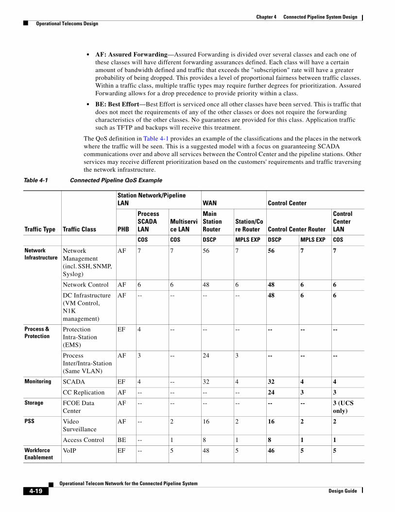
Chapter 4 Connected Pipeline System Design Operational Telecoms Design
• AF: Assured Forwarding—Assured Forwarding is divided over several classes and each one of these classes will have different forwarding assurances defined. Each class will have a certain amount of bandwidth defined and traffic that exceeds the "subscription" rate will have a greater probability of being dropped. This provides a level of proportional fairness between traffic classes. Within a traffic class, multiple traffic types may require further degrees for prioritization. Assured Forwarding allows for a drop precedence to provide priority within a class.
• BE: Best Effort—Best Effort is serviced once all other classes have been served. This is traffic that does not meet the requirements of any of the other classes or does not require the forwarding characteristics of the other classes. No guarantees are provided for this class. Application traffic such as TFTP and backups will receive this treatment.
The QoS definition in Table 4-1 provides an example of the classifications and the places in the network where the traffic will be seen. This is a suggested model with a focus on guaranteeing SCADA communications over and above all services between the Control Center and the pipeline stations. Other services may receive different prioritization based on the customers' requirements and traffic traversing the network infrastructure.
Table 4-1 Connected Pipeline QoS Example
Traffic Type Traffic Class
Station Network/Pipeline LAN WAN Control Center
PHB
Process SCADA LAN
Multiservice LAN
Main Station Router
Station/Core Router Control Center Router
Control Center LAN
COS COS DSCP MPLS EXP DSCP MPLS EXP COS
Network Infrastructure
Network Management (incl. SSH, SNMP, Syslog)
AF 7 7 56 7 56 7 7
Network Control AF 6 6 48 6 48 6 6
DC Infrastructure (VM Control, N1K management)
AF -- -- -- -- 48 6 6
Process & Protection
Protection Intra-Station (EMS)
EF 4 -- -- -- -- -- --
Process Inter/Intra-Station (Same VLAN)
AF 3 -- 24 3 -- -- --
Monitoring SCADA EF 4 -- 32 4 32 4 4
CC Replication AF -- -- -- -- 24 3 3
Storage FCOE Data Center
AF -- -- -- -- -- -- 3 (UCS only)
PSS Video Surveillance
AF -- 2 16 2 16 2 2
Access Control BE -- 1 8 1 8 1 1
Workforce Enablement
VoIP EF -- 5 48 5 46 5 5
4-19Operational Telecom Network for the Connected Pipeline System
Design Guide

Chapter 4 Connected Pipeline System Design Operational Telecoms Design
Classification, marking, and policing should be performed at the edge of the network as close to the traffic sources as possible. At the edge, ports will not be trusted and all traffic will be required to be classified and marked. A network traffic profile including traffic types and expected bandwidth should be provided to police and protect the classes from oversubscription. This can be used to help provide anomalies within the network too as part of an overall security implementation when traffic is seen behaving outside of the profile. Queuing will be provided throughout the network at all hops.
At each layer of the overall architecture, the QoS implementation may be slightly different. This could be due to the various equipment capabilities or the different traffic types that may be seen throughout the overall architecture. A good example of this is electrical protection traffic that will in most instances remain with the main station environment.
Network Management DesignWithin the end-to-end pipeline management system, the operators in the Control Center need to have a fully integrated management system. Integrating the networking management systems into the SCADA operational environments is a key requirement. Operator stations at the Control Center are manned continuously and operators need to be aware of any issues within the networking infrastructure. Alarms and notifications of events should be displayed to the operator.
For this phase, basic system configuration and report management will be validated. Prime infrastructure can provide configuration management of the Cisco IE 2000, Cisco IE 4000, and the Cisco ASR 903 routers. Cisco ASDM can be utilized to provide policy management on the ASA firewalls.
Prime Infrastructure
Cisco Prime Infrastructure delivers a single, unified platform for network service provisioning, monitoring and assurance and change and compliance management. It accelerates device and services deployment and helps you rapidly resolve problems that can affect the end-user experience. It helps minimize the amount of time you spend managing the existing network so you can maximize the time you spend in supporting business growth. A single-pane-of-glass solution provides complete end-to-end infrastructure management, reducing the need for multiple tools and lowering operating expenses and training costs. For more information, please refer to Resilient Ethernet Protocol Overview at the following URL:
• http://www.cisco.com/c/en/us/products/cloud-systems-management/prime-infrastructure/index.html
Sync/Timing PTP 1588 EF 4 -- -- -- -- -- --
NTP AF 7 7 56 7 56 7 7
Low Priority Maintenance
TFTP, Backups, Patching
BE 0 0 0 0 0 0 0
Table 4-1 Connected Pipeline QoS Example (continued)
Traffic Type Traffic Class
Station Network/Pipeline LAN WAN Control Center
PHB
Process SCADA LAN
Multiservice LAN
Main Station Router
Station/Core Router Control Center Router
Control Center LAN
COS COS DSCP MPLS EXP DSCP MPLS EXP COS
4-20Operational Telecom Network for the Connected Pipeline System
Design Guide
Chapter 4 Connected Pipeline System Design Operational Telecoms Design
Cisco Adaptive Security Device Manager
Cisco Adaptive Security Device Manager (ASDM) can be accessed directly with a Web browser from any Java plug-in-enabled computer on the network, providing security administrators with rapid, secure access to their Cisco ASA Firewalls. ASDM allows the user to configure, monitor, and troubleshoot Cisco firewall appliances with a user-friendly application. Ideal for small or simple deployments, the Cisco ASDM provides the following:
• Setup wizards that help you configure and manage Cisco firewall devices
• Powerful real-time log viewer and monitoring dashboards that provide an at-a-glance view of firewall appliance status and health
• Troubleshooting features and powerful debugging tools such as packet trace and packet capture
Event Notification
Fault management, security events, and alarms should be presented to the operator should events in the network occur. Typically Syslog and SNMP are the mechanisms to report to a fault management system which presents the notification to an operator. Where possible, SNMP V3 should be configured to provide an extra level of security.
Out of Band Management
A separate OOB network should be deployed to provide a dedicated infrastructure to support the management traffic. The OOB network segment hosts console servers, network management stations, AAA servers, analysis and correlation tools, NTP, FTP, Syslog servers, network compliance management, and any other management and control services. An OOB management network should be deployed using the following best practices:
• Provide network isolation
• Enforce access control
• Prevent data traffic from transiting the management network
• Enforce secure use of network management traffic (SSH, SNMP v3)
If an OOB network is not viable, then a dedicated VLAN should be used for the management network following the same best practices above and classifying/prioritizing management traffic using QoS.
Role-Based Access Control
Business practices and levels of expertise may dictate the management practice, roles, and responsibilities of the system. Companies are merging the boundaries between IT and OT where these have historically remained separate domains. Staff may have differing levels of knowledge to support the applications and infrastructure so where possible access levels should be provided to personnel.
RBAC using authentication, authorization, and accounting (AAA) should be deployed to provide secure access to the networking devices. It is a method of restricting or authorizing system access for users based on a user's identity and role. This role consists of privileges that will be assigned to the user. These privileges can be very granular; for example, a user can be restricted from accessing particular commands and strings.
4-21Operational Telecom Network for the Connected Pipeline System
Design Guide

Chapter 4 Connected Pipeline System Design Operational Telecoms Design
System Components
Cisco Products
Table 4-2 lists Cisco components.
Scheider Electric Products
Table 4-3 lists Schneider Electric components.
Table 4-2 Cisco Components
Vendor Model Software Version
Cisco ASR 903 15.5(2)S
Cisco ASR 902 15.5(2)S
Cisco ASA 55X5-X 9.2(3)4
Cisco IE 2000 15.0(2)EA1
Cisco IE 4000 15.2(2)EA
Table 4-3 Schneider Electric Components
Vendor Model Software Version Product
Schneider Electric M340 RTU/PLC
Schneider Electric SCADAPack350 RTU/PLC
Schneider Electric M580 RTU/PLC
4-22Operational Telecom Network for the Connected Pipeline System
Design Guide

Chapter 4 Connected Pipeline System Design Operational Telecoms Design
4-23Operational Telecom Network for the Connected Pipeline System
Design Guide

Operational TelecomDesign Guide
A
P P E N D I X A Acronyms and InitialismsTable A-1 lists acronyms and initialisms for the Operational Telecom Network for the Connected Pipeline System Design Guide.
Table A-1 Acronyms and Initialisms
AAA Authentication, Authorization, and Accounting
ASDM Cisco Adaptive Security Device Manager
ACL Access Control List
ARP Address Resolution Protocol
ASA Cisco Adaptive Security Appliance
BLISS Baseline Integrated SCADA System
CDMA Code Division Multiple Access
CoPP Control Plane Policing
COTS consumer off the shelf
CVD Cisco Validated Design
DAI Dynamic ARP Inspection
DHCP Dynamic Host Configuration Protocol
DMZ Demilitarized Zone
DNA Dynamic Network of Applications
DSS Decision Support System
E&P Exploration and Production
EFM Ethernet in the First Mile
EPLMS Schneider Electric’s Enterprise PipeLine Management System
FCAPS Fault, Configuration, Accounting, Performance and Security
FTP File Transfer Protocol
HBA Host Bus Adaptor
HMI Human Machine Interface
IAC Identification, Authentication & Control
ICS Industrial Control System
IDMZ Industrial Demilitarized Zone
1 Network for the Connected Pipeline System

Appendix
IDS Intrusion Detection System
IEC International Electrotechnical Commission
IED Intelligent Electronic Device
IMC Cisco Integrated Management Controller
IPS Intrusion Protection System
ISA International Society of Automation
IoT Internet of Things
LLD Low Level Design
LNG Liquid Natural Gas
LUN Logical Unit Number
NFTS New Technology File System
NGL Natural Gas Liquid
NIST National Institutes of Standards and TEchnology
NTS Network Time Server
SNTP Simple Network Time Protocol
OOB Out of Band
OTN Operational Telecom Network
PCD Process Control Domain
PCN Process Control Network
PAGA Public Address and General Alarm
PIG Pipeline Inspection Gauge
PHMSA Pipeline and Hazardous Materials Safety Administration
PLC programmable logic controller
PMS Pipeline Management System
RAID Redundant Array Of Independent Disks
RBAC Role-Based Access and Control
RCS Schneider Electric Remote Client Service
RDF Restricted Data Flow
RDP Remote Desktop Protocol
RTU remote terminal unit
QoS Quality of Service
SAN Storage Area Network
SLA Service Level Agreements
SPOF single point of failure
SCADA Supervisory Control and Data Acquisition
STP Spanning Tree Protocol
TACACS+ Terminal Access Controller Access-Control System Plus
Table A-1 Acronyms and Initialisms (continued)
2Operational Telecom Network for the Connected Pipeline System
Design Guide

Appendix
TCO Total Cost of Ownership
TRE Timely Response to Events
VHD Virtual Hard Disk
VIC Virtual Interface Card
VLAN Virtual Local Area Network
vNIC Virtual Network Interface Card
VoIP Voice over IP
vPC Virtual Port Channel
VSAN Virtual Storage Area Network
WAN Wide Area Network
Table A-1 Acronyms and Initialisms (continued)
3Operational Telecom Network for the Connected Pipeline System
Design Guide

Appendix
4Operational Telecom Network for the Connected Pipeline System
Design Guide