operations and maintenance manual - bazell
TRANSCRIPT

CF 65 G
Operations and Maintenance Manual
Industrial centrifuges available in manual clean, full automatic, portable skids, tank systems and custom built systems to suit process requirements.
S e r v i n g I n d u s t r y W o r l d w i d e S i n c e 1 9 8 3
5066 Commercial Circle Concord, CA. 94520 (800) 288-2465 (925) 603-0901 Fax
email: [email protected] web: www.bazell.com
Rev. Apr. 2001 Copyright 1996-2016 Bazell Technologies Corporation. All rights reserved. Bazell Technologies reserves the right to change specification without
notice. Microseparator and the Microseparator logo are registered trademarks of Bazell Technologies Corporation.

Page 2
H:\CUSTOMER DOCUMENTATION\Manuals\Original Manuals\M000036_A - CF 65G Manual.docx 1996-2016 Bazell Technologies Corporation. All rights reserved.
TABLE OF CONTENTS
TABLE OF CONTENTS ....................................................................................... 2
SPECIFICATIONS - MICROSEPARATOR ........................................................ 4
COMPANY PROFILE ......................................................................................... 5
APPLICATIONS ................................................................................................ 5
PARTS & SERVICE ............................................................................................ 5
RECEIVING AND INSPECTION ......................................................................... 6
OPERATOR SAFETY .......................................................................................... 6
PRINCIPLE OF OPERATION - MICROSEPARATOR ......................................... 7
TYPICAL PIPING LAYOUT ................................................................................ 8
CLEANING FREQUENCY CALCULATION ........................................................... 9
FLOW RATE INFORMATION ............................................................................. 9
INITIAL START UP ......................................................................................... 10
OPERATION ................................................................................................... 11 Preliminary Checks ..................................................................................................................... 12 Start up..................................................................................................................................... 12 Shut Down ................................................................................................................................ 12 Control Panel Operation .............................................................................................................. 14
MICROSEPARATOR ASSEMBLY CROSS SECTION ........................................ 16 Drawing# 5A125020 .................................................................................................................. 16 CF 65 G Microseparator Cross Section Parts List - DWG# 5A125020 ............................................... 17
ROTOR CROSS SECTION ................................................................................ 18 Drawing# 5A122000 .................................................................................................................. 18 Rotor Assembly Parts List - Drawing# 5A122000 .......................................................................... 19 Rotor Assembly Parts List (Cont’d) - Drawing# 5A122000 .............................................................. 20 Scraper Drive Cross Section Drawing 59124002 – CF 65 ................................................................ 21

Page 3
H:\CUSTOMER DOCUMENTATION\Manuals\Original Manuals\M000036_A - CF 65G Manual.docx 1996-2016 Bazell Technologies Corporation. All rights reserved.
Scraper Drive Assembly Parts List Dwg 58124002 – CF 65 ............................................................ 22 Stopper Assembly ...................................................................................................................... 24 Drawing #5A125010 .................................................................................................................. 24 Stopper Assembly Parts List - Drawing #5A125010 ....................................................................... 25
OUTLINE MICROSEPARATOR ON FRAME .................................................... 25 Drawing# 5A112004 .................................................................................................................. 26
TYPICAL PIPING LAYOUT .............................................................................. 26 Drawing# 5A113001 .................................................................................................................. 27
PNEUMATIC ................................................................................................... 28 Drawing# 5A132013 .................................................................................................................. 28
MAINTENANCE .............................................................................................. 29
TROUBLE SHOOTING ..................................................................................... 30
ELECTRICAL PRINTS ..................................................................................... 31 Drawing # - 58131300 Series ...................................................................................................... 31
WARRANTY .................................................................................................... 32

Page 4
H:\CUSTOMER DOCUMENTATION\Manuals\Original Manuals\M000036_A - CF 65G Manual.docx 1996-2016 Bazell Technologies Corporation. All rights reserved.
SPECIFICATIONS - MICROSEPARATOR Model CF 65 G Motor 2 HP (1.5KW), 230/460 3ph
60 Hz, 1715 RPM, TEFC, 4 Pole, Frame 100 L, Induction Motor, FLA 5.2/2.6
Solids Discharge Automatic Nominal Capacity * 20 GPM Rotor Volume 1.2 Gal. Construction Material
Centrifuge Cabinet 304 Stainless Steel Mounting Stand Cast Iron Centrifuge Rotor Aluminum Scraper Assembly 304 Stainless Steel Gaskets Buna N
Shipping Data Length 53 in. (1346 mm) Width 39 in. (991 mm) Height 68 in. (1727 mm) Volume 81 Cu Ft. (2.3 cu. m.) Weight 1250 lb. (567 kg.) Operating Temperature Limit 194º F (90º C) Piping Connections Dirty Inlet 1 in. NPT Female Effluent Outlet 3 in. NPT Female Drain Case (2) 1.5 in. NPT Female Flush (2) 1 in. NPT Female Utility requirements Electrical 230/460 Volt, 40 Amps, 3 Phase, 1.5 KW Air 75 - 150 psig ¼ in. NPT Female inlet

Page 5
H:\CUSTOMER DOCUMENTATION\Manuals\Original Manuals\M000036_A - CF 65G Manual.docx 1996-2016 Bazell Technologies Corporation. All rights reserved.
COMPANY PROFILE Bazell Technologies is a closely held California Corporation devoted exclusively to the manufacture of world-class industrial fluid clarification systems. Founded in 1983, the Company pioneered the application of fully automated basket centrifuges in a wide variety of industrial applications. Today, the Company operates internationally, solving complex fluid clarification problems for many of the world’s leading industrial companies. The staff of Bazell Technologies Corporation collectively possesses almost 100 years of centrifuge experience. The Company’s technical staff is made up of a team of process industry professionals with expertise in the areas of chemical, mechanical, and electrical engineering. The proprietary technology of the Microcone fluid processing system is evidence of the Company’s commitment to continued industry leadership. In addition to being a tier one major equipment supplier to the automotive industry, the Company is an industry leader in other key markets including aerospace, computer component, scientific and consumer optics, metalworking, commercial laundry, wire and cable, sporting goods, and the general industrial manufacturers who supply those industries. The Company’s modern facilities in the San Francisco Bay area continue to expand rapidly in response to the ever-increasing demand for its technologies. The market-leading growth rate of the Company confirms a business strategy calling for the highest quality solutions backed by experienced industrial professionals committed to total customer satisfaction.
APPLICATIONS The Microseparator® is a liquid/solid separator with a broad range of industrial applications. Over 30,000 of these machines have been distributed worldwide over the past twenty-five years. Microseparators® can be found cleaning up water, oil, and water soluble coolants of solids like aluminum, carbides, glass, steel, paint pigment, sand, ceramics, and tank scale, to name only a few. Now that you have purchased your first Microseparator® you have at your disposal the ability to test the machine on other applications in your facility. Additionally, we have special test modules available for this purpose. Your Microseparator® sales professional will be glad to assist you in determining the appropriate model and specification to suit your application.
PARTS & SERVICE No voice mail! When you call us you will deal with a real human being. Bazell Technologies maintains a very large inventory of spare parts and complete assemblies ready for immediate overnight shipment worldwide. At our factory in Concord, CA. we offer complete machine rebuilding to bring your Microseparator back up to full operating standards with upgrades. Field service is available on site by our service technicians. Our team of process specialists brings many years of mechanical, electrical, and chemical engineering experience to bear on installation planning, process optimization, and problem resolution. Our services are also available on a consulting basis.

Page 6
H:\CUSTOMER DOCUMENTATION\Manuals\Original Manuals\M000036_A - CF 65G Manual.docx 1996-2016 Bazell Technologies Corporation. All rights reserved.
RECEIVING AND INSPECTION As soon as possible upon receipt of shipment, machine should be uncrated and packing list checked. Any shortages should be reported to Bazell Technologies immediately. If damage has occurred during transit, file a claim with the carrier and notify Bazell Technologies of such actions as soon as possible.
OPERATOR SAFETY All personnel responsible for operating the Microseparator should be required to read these safety and cleaning procedures prior to operation. Remember, centrifuges incorporate rotating components that should be treated with the same caution as other rotating devices. Important safety devices are built into each Microseparator. Please carefully observe the following safety notices. Always disconnect and lock out the power source before working on or near the
Microseparator rotor or drive motor. Motor controls should conform to instructions given in the installation manual provided with
the Microseparator. Motor controllers must be securely and adequately grounded according to NEC and local codes of the specific area.
Do not operate the Microseparator if severe vibration is observed. Generally, vibration is caused by incomplete rotor cleaning, see procedures below.
Note: Do not operate the Microseparator if the vibration switch (See Assembly DWG) is faulty.

Page 7
H:\CUSTOMER DOCUMENTATION\Manuals\Original Manuals\M000036_A - CF 65G Manual.docx 1996-2016 Bazell Technologies Corporation. All rights reserved.
PRINCIPLE OF OPERATION - MICROSEPARATOR The automatic Microseparator is a centrifugal processing tool for the removal of solid particulate from a liquid medium. Feed enters at the dirty liquid inlet (A) and progresses upwardly through the rotor body (B). Centrifugal force is applied to the liquid stream in the main body of the rotor causing solid particulate to move toward the rotor wall. Clarified liquid exits the bottom of the rotor (C). The clean liquid discharges into the segregated upper frame and drains from the clean liquid outlet (D). Solids deposited in the rotor are compacted by centrifugal force and allowed to build until removed during the cleaning cycle. A feed timer or a parts counter are used to determine when the cleaning cycle will be initiated. During the feed cycle the lower cabinet is flushed continuously at (E) with dirty liquid to minimize the accumulation of solids in that area. When the cleaning cycle initiates, the feed pump stops flow to the Microseparator® or a valve diverts flow. The drive motor is de-energized and the rotor coasts, or via optional DC braking is brought to a full stop. Any residual liquid remaining in the rotor will flow into the lower cabinet (F) and then drain back to the process tank. Only drain liquid is removed from the frame in this manner dramatically reducing misting of process liquid. The accumulated solids are removed from the rotor in the following manner. First, a solenoid valve energizes and the drain plate is pneumatically retracted (G). This movement opens the bottom of the rotor to the sludge receptacle below. A second air solenoid pneumatically operates the stopper assembly (H) which locks the rotor in position and engages the scraper drive (I). Clockwise and counter clockwise rotations of the scraper clean the solid particulate from the walls of the rotor causing the solids to drop into the sludge receptacle below. After the sludge has been removed from the rotor, all of the above operations are reversed and the Microseparator® returns to full speed . Normal operation will continue until the system is shut down or vibration is detected which initiates an automatic cleaning cycle. On normal shut down, a complete cleaning cycle is initiated to ensure that the Microseparator shuts down clean.

Page 8
H:\CUSTOMER DOCUMENTATION\Manuals\Original Manuals\M000036_A - CF 65G Manual.docx 1996-2016 Bazell Technologies Corporation. All rights reserved.
TYPICAL PIPING LAYOUT
The following illustrations concerning the typical piping layout are presented to give installers general guidelines to follow.
Primary Piping Connections
Item Material Dimension
Centrifuge Inlet 304 SS 1” NPT Outlet 304 SS 3” NPT Female Lower Case Drain 304 SS 1 ½” NPT Female Lower Drain Case Flush Fitting Inlets (2 ea.) 304 SS 1” NPT
Dirty Process liquid is pumped into the 1” Tee (1). Flow is then diverted to both the centrifuge inlet (2) and the lower case drain flush inlets (3). There is a 1" 2-Way Ball Valve (4) that regulates flow into the centrifuge (See Flow Rate Information Section for proper adjustment). The other ½" 2-Way Ball Valve (5) regulates flow into the ½" lower case drain flush inlets (3) to allow debris to be flushed out of the lower case drain at (6) and return the liquid/debris to the process reservoir. Flow through the lower case drain should be set at a rate of 10-15 GPM. This discharge should slope downward to the sump with no restrictions in the line. Clarified liquid is discharged from the centrifuge case via the 3” NPT female outlet on the side of the case (7). Outlet piping should terminate above liquid level so that fluid cannot back up in the outlet line. If 304 SS or black iron pipe is used, install a flexible coupling along the vertical drop or shortly after the horizontal turn in the pipeline.
1
2
3
3
45
6
7

Page 9
H:\CUSTOMER DOCUMENTATION\Manuals\Original Manuals\M000036_A - CF 65G Manual.docx 1996-2016 Bazell Technologies Corporation. All rights reserved.
CLEANING FREQUENCY CALCULATION The volume of solids present controls the cleaning interval, thus the cleaning interval may be calculated as: (Rotor Volume)
Cleaning Interval = ------------------------------------- (Feed Rate) x (Percent Solids)
It is important to note the result of action or inaction in this matter: Cleaned frequently: Solids may be slightly more wet but easier to remove Cleaned infrequently: Allowed to fill with solids and continue feeding liquid, the rotor will pass dirty liquid back to the process. Solids may be more difficult to remove from the rotor depending on their consistency.
FLOW RATE INFORMATION The 65 Series Microseparators have a maximum flow rate of 15 GPM on water. Flow rates in excess of the maximum will overflow the rotor case and potentially shorten bearing life. The importance of maintaining flow at or below this value cannot be overestimated. Periodically, flow rate should be checked manually to insure that the proper rate is being maintained. The most accurate and simple method for verification utilizes a watch and bucket. The following table is offered for quick reference.
CONTAINER CONTAINER SIZE (GALS) SIZE (GALS) 1 5
FLOW RATES GPM
TIME TO FILL
CONTAINER(SECONDS)
TIME TO FILL
CONTAINER(SECONDS)
5 12.00 60.0010 6.00 30.0015 4.00 20.0020 3.00 15.00

Page 10
H:\CUSTOMER DOCUMENTATION\Manuals\Original Manuals\M000036_A - CF 65G Manual.docx 1996-2016 Bazell Technologies Corporation. All rights reserved.
INITIAL START UP Prior to beginning operation of the automatic Microseparator for the first time, some preliminary checks and actions are necessary. PLEASE FOLLOW THESE INSTRUCTIONS CAREFULLY. 1. Remove access cover from scraper drive assembly and check: - Main drive belt for proper tension. Adjust if necessary. - Scraper drive tension and adjust if necessary. - Turn rotor by hand and check freedom from noise and ease of rotation. - Remove any lashings or coverings that may be protecting parts during shipment.
- All assemblies in this area paying careful attention to the limit switches and stopper assembly. Both switches should be CLOSED in this UP position.
2. Check foundation for proper lagging and support. 3. Open control console and check for the following: - Loose wiring at termination points.
- Ground wire at E must be continuous with the separator frame and the frame well grounded. Check using continuity tester. - Voltage is appropriate for wiring of transformer circuit. Revise transformer wiring to conform to plant voltage.
- Check that all motors are properly wired for the voltage selected. - Heaters in motor starters are properly set with appropriate amps for the respective motors at the appropriate voltage. - Main power breaker is open, as well as auxiliary circuit breakers. 4. Disconnect air supply to Microseparator. 5. Close process feed valve (if provided) and disable feed to Microseparator. 6. Close main power breaker in Microseparator control panel and check voltage. 7. Close breaker and check incoming voltage and at transformer secondary. Voltage should be
110-120 volts. If voltage is higher than 120 V, rewire transformer to provide lower voltage. 8. Close remaining circuit breakers. 9. Begin operational checks with the Microseparator running. SERIOUS MECHANICAL
DAMAGE CAN OCCUR SHOULD THE ELECTRICAL CONTROLS INITIATE A CLEANING CYCLE WHEN THE MACHINE IS ROTATING. A LARGE HEX SOCKET MAY DEPRESS AGAINST A LARGE HEX NUT THAT IS ROTATING IF THE CONTROLS ARE NOT SET CORRECTLY. SINCE THE AIR HAS NOT BEEN CONNECTED, THE ABOVE OCCURRENCE IS NOW IMPOSSIBLE.
10. "JOG" Microseparator drive motor by selecting pressing the SYSTEM START button. Immediately press the EMERGENCY STOP button and observe direction of rotation. (See directional arrow on cover adjacent to motor). DO NOT CHANGE YET IF ROTATION IS WRONG. Release EMERGENCY STOP.
11. Again press the SYSTEM START button and let Microseparator come to full speed. NOTE ANY UNUSUAL VIBRATION. DO NOT PROCEED IF VIBRATION IS ABOVE ABOUT 3 MILS OR IF QUESTIONABLE VIBRATION IS OBSERVED. If Microseparator is running quietly at full speed, check motor amps against motor nameplate data.
12. Press the MANUAL CLEAN button. The Microseparator should now begin a clean cycle. The drive motor will be turned OFF, and the rotor will come to a full stop.
13. Just as the rotor comes to a complete stop. The Drain Timer should begin timing at this point, wait for timer to time out (1-2 minutes).

Page 11
H:\CUSTOMER DOCUMENTATION\Manuals\Original Manuals\M000036_A - CF 65G Manual.docx 1996-2016 Bazell Technologies Corporation. All rights reserved.
14. Scraper drive motor should begin rotation now but will not depress against hex nut because there is no air pressure. Note Direction of first rotation. Should be clockwise looking down. If this direction is wrong, excessive torque will be required in scraping of cake from rotor.
A: If rotation of scraper drive is wrong and rotation of rotor was wrong, then reverse incoming power wiring. B: If rotation of rotor was correct and rotation of scraper drive was wrong, then revise wiring at scraper drive starter. 13. Set Feed Cycle Timer for appropriate setting depending on % of solids in feed. See
Cleaning Frequency Calculation and Control Panel Operations Section for details. 14. Connect air supply and check regulator and oil supply in oiler. Set air supply to 60 Psig (4
Bar). Set oiler to give about 1 drop for each 25 cycles of air cylinders as follows: - Close oiler flow regulation valve on top of oiler (clockwise).
- Remove rubber cover on solenoid valve manual over-ride switch. - Depress over-ride switch with screwdriver to actuate solenoid valve. - Open oil valve adjust knob to give about one drop per each 25 cycles. - Set air purge regulator to about 0.5 bar (7 Psig).
15. Press the SYSTEM START button. Allow rotor to come to full speed and check motor amps. against nameplate rating, and again check for unusual noise or excessive vibration.
16. Press the MANUAL CLEAN button and observe the cleaning cycle. Check: - Rotor stop and operation of the Variable Frequency Drive. - Forward and reverse action of scraper continues for duration of the scraper timer
setting. 17. Check operation of vibration switch. With separator running at full speed, jar the
Microseparator slightly by pushing firmly against side of frame. This should cause the control to initiate a cleaning cycle thus simulating excessive vibration due to failure to clean properly.
18. SYSTEM STOP function check. This procedure will be used by operators to shut the system down for an extended period of time (overnight, weekends) and the rotor will be in a clean condition. With the Microseparator in full operation press the SYSTEM STOP button and observe the following:
- Cleaning cycle will start immediately. - When cleaning cycle is complete, the rotor will start and run for setting of 10
seconds to check rotor condition before shut down. If vibration is indicated, cleaning cycle will repeat. The control will repeat this sequence until it is determined the rotor is clean.
- Operation will now be stopped.
OPERATION The following procedures are intended as a guide for the daily operation of the Microseparator. They should be used only after the machine has been properly installed and commissioned by a qualified technician. ALL OPERATORS OF THE MICROSEPARATOR SHOULD READ THE ENTIRE INSTRUCTION MANUAL AND KNOW WHERE TO FIND A COPY AT ALL TIMES. TIMER SETTINGS SHOULD NEVER BE ADJUSTED WITHOUT PRIOR REVIEW BY TRAINED PERSONNEL OR BAZELL TECHNOLOGIES. SEVERE

Page 12
H:\CUSTOMER DOCUMENTATION\Manuals\Original Manuals\M000036_A - CF 65G Manual.docx 1996-2016 Bazell Technologies Corporation. All rights reserved.
DAMAGE TO MACHINE CAN OCCUR IF DONE IMPROPERLY. PRELIMINARY CHECKS Lag bolts - check for tightness. Piping - visual check of fittings, return piping to proper receiving vessel. Air supply
- set main air regulator to 4 bar (60 psig.) - set air purge regulator to .5 bar (7 psig.) - check oil supply, add if necessary Lower drain cabinet - check for solids build-up, clean if necessary. Sludge drum: Empty if necessary.
START UP 1. Turn main breaker to on position. White "power" pilot will come on. 2. Press the SYSTEM START button. Listen for unusual noises or vibrations. The machine is
equipped with a vibration switch that will start the machine into a cleaning operation if sufficient vibration is present.
3. The machine will not open feed valve (if installed) to allow dirty liquid into rotor until delay timer has finished its cycle. Typical setting is 10 seconds.
4. Observe the following: a) Flow from machine is unrestricted and end of return pipe is above fluid sump level. Check
flow rate and adjust if necessary. b) Check lower drain cabinet for flow from rotor down to cabinet. Flows of ½ gpm are normal.
Be sure flow from cabinet to return sump is unrestricted. Flows over 1 gpm should be corrected. Feed rate of machine should be checked and adjusted. Excessive feed to machine will cause excessive flow to the drain cabinet.
c) Check effluent for clarity. See troubleshooting guide if liquid is excessively dirty. 5. The machine is now in an automatic mode and will continue normal operation until machine
is manually stopped, the feed timer has timed out, the power is interrupted, or excessive vibration starts a cleaning cycle.
6. When the feed timer completes its cycle, the machine will automatically clean itself. It is a good idea for new operators to observe this cleaning operation to familiarize themselves with the cleaning cycle.
SHUT DOWN At the end of the production day, use the SYSTEM STOP button to shut down the machine. This will start a series of actions. 1. Machine will go through a complete cleaning cycle. 2. The machine will now attempt to restart to check for solids in the rotor. 3. If solids are still present in rotor, vibration will be present and force the machine into another cleaning cycle. This cycle will repeat until vibration is no longer present.

Page 13
H:\CUSTOMER DOCUMENTATION\Manuals\Original Manuals\M000036_A - CF 65G Manual.docx 1996-2016 Bazell Technologies Corporation. All rights reserved.
4. Machine will shut down until started again. Caution: Do not use Emergency Stop or turn off main breaker to shut down machine during normal shut down procedure. The Microseparator should always go through cleaning cycle before shutting down for maintenance or any lengthy period of time.

Page 14
H:\CUSTOMER DOCUMENTATION\Manuals\Original Manuals\M000036_A - CF 65G Manual.docx 1996-2016 Bazell Technologies Corporation. All rights reserved.
CONTROL PANEL OPERATION The Startup Screen will appear when the unit is first turned on. It should look like the diagram below. DRAIN PLATE / AUTO MANUAL: Pressing the DRAIN PLATE / AUTO MANUAL button and switching to manual will allow operators to manually retract the Drain Plate with the centrifuge offline. Use this only to visually inspect the lower cabinet and/or rotor. This button will only work when the Microseparator is not running. Do not open during operation. This switch should never be left in the manual position. This button should normally be set to AUTO. ALARM ACK: When the system is experiencing an alarm fault, the alarm fault will appear on the upper LCD screen. Press the ALARM ACK button to acknowledge the alarm fault. Disconnect main power and lock out if necessary. Correct the fault and retest by running the system. If necessary, feel free to call Bazell Technologies for technical assistance. SYSTEM START: Pressing on the SYSTEM START button initiates the system (All system devices must be set in the auto mode). SYSTEM STOP: Pressing the SYSTEM STOP button shuts down the system. When shutting down the Microseparator for maintenance or any lengthy period of time (Overnight), be sure to press the SYSTEM STOP button. The system will automatically enter into a cleaning cycle, restart to check for vibration, and then shutdown. Only use the Emergency Stop push button located on the control panel in case of emergencies and when a final cleaning cycle is not desired. MANUAL CLEAN: Pressing the MANUAL CLEAN button immediately starts a cleaning cycle.
BAZELL TECHNOLOGIES CF 65 Series
DRAIN PLATE AUTO/
MANUAL
ALARM ACK
SYSTEM START
SYSTEM STOP
MANUAL CLEAN
FEED CYCLE TIMER
OTHER TIMERS
MAIN SCREEN
1 2 3
4 5 6
7 8 9
0

Page 15
H:\CUSTOMER DOCUMENTATION\Manuals\Original Manuals\M000036_A - CF 65G Manual.docx 1996-2016 Bazell Technologies Corporation. All rights reserved.
Once the cycle is finished, the machine will restart operation and the feed cycle timer will be reset. FEED CYCLE TIMER: The feed cycle timer setting represents the time allotted for the Microseparator to run before it will initiate a cleaning cycle. Pressing the FEED CYCLE TIMER will switch the LCD screen to a timer setting screen. The two timer indicators display the preset feed cycle time value and the time elapsed. To change the feed cycle time value, press the CLEAR button. Type in the new time (In minutes) and press ENTER. Once set, press SEPARATOR to save and exit. The elapse time indicator serves to display how much time has elapsed since the last cleaning cycle. OTHER TIMERS: The OTHER TIMERS button allows operators to set system timer settings other than the Feed Cycle timer. Once the OTHER TIMERS button is pressed, the screen will switch to the Scraper Timer Setting (Setting in seconds). Set timer by pressing the CLEAR button, enter a new value in seconds, and then press the ENTER button. Once set, press the SEPARATOR button to exit to the main screen. All other system timers are password protected, and can be accessed by pressing the OTHER TIMERS button twice. The password is 5066. These timers are factory preset and should not need adjustment. Contact Bazell Technologies Corporation for information regarding these settings. MAIN SCREEN: Press the MAIN SCREEN button to view the system program filename. This also the initial screen operators will see when the control panel is first powered on. NOTE: Do not use Emergency Stop push button or turn off main breaker to shut down machine during a normal shut down procedure. Instead, press the System Stop button. The Microseparator should always go through cleaning cycle before shutting down for maintenance or any lengthy period of time.
Page 16
H:\CUSTOMER DOCUMENTATION\Manuals\Original Manuals\M000036_A - CF 65G Manual.docx 1996-2016 Bazell Technologies Corporation. All rights reserved.
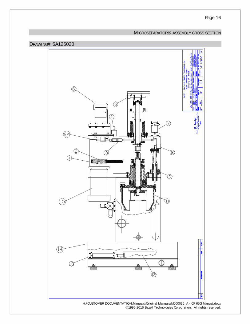
MICROSEPARATOR ASSEMBLY CROSS SECTION DRAWING# 5A125020

Page 17
H:\CUSTOMER DOCUMENTATION\Manuals\Original Manuals\M000036_A - CF 65G Manual.docx 1996-2016 Bazell Technologies Corporation. All rights reserved.
CF 65 G MICROSEPARATOR CROSS SECTION PARTS LIST - DWG# 5A125020 ITEM # QTY PART # DESCRIPTION MATERIAL/
SPECIFICATION 1 2 2065703 DRIVE BELTS Reinforced Rubber A 42 2 1 2065712 PULLEY Cast Iron A2132 3 1 2065713 DRIVE CHAIN RS-100 4 1 2150707A VIBRATION SWITCH OMRON D7A3 5 1 5080004 LIMIT SWITCH OMRON WLAC2 6 1 5111149 GEAR MOTOR 1/2 HP 6A 1 2100421 SPROCKET STEEL 7 1 6140025 AIR CYLINDER SMC 40 X 25 8 1 5080004 LIMIT SWITCH OMRON WLAC2 9 1 2065500 STOPPER ASSEMBLY (SEE DWG. # 5A125010) 11 1 2065130 ROTOR ASSEMBLY (SEE DWG. # 5A122000) 12 1 2065722 SLIDE PLATE ASSEMBLY 304 SS 13 1 6140200 AIR CYLINDER CG1BN 40 X 200 14 1 2065751 LOWER CASE 304 SS 15 1 5110052 MOTOR 2 HP TEFC * SCRAPER DRIVE GEAR MOTOR: 1/2 HP (0.4 kW), 230/460 V, 3 PH, 40 RPM @ 60 Hz, FLA 1.6/0.8 GEAR SIZE F

Page 18
H:\CUSTOMER DOCUMENTATION\Manuals\Original Manuals\M000036_A - CF 65G Manual.docx 1996-2016 Bazell Technologies Corporation. All rights reserved.
ROTOR CROSS SECTION DRAWING# 5A122000

Page 19
H:\CUSTOMER DOCUMENTATION\Manuals\Original Manuals\M000036_A - CF 65G Manual.docx 1996-2016 Bazell Technologies Corporation. All rights reserved.
ROTOR ASSEMBLY PARTS LIST - DRAWING# 5A122000
ITEM # QTY PART # DESCRIPTION MATERIAL/ SPECIFICATION
2065130 Rotor Assembly (Complete) 1 1 8111050 Cap Screw Steel 2 1 7311000 Lock Washer Steel 3 1 7411000 Flat Washer Steel 4 1 2065104 Scraper Drive Nut Steel 5 1 2065105 Rotor Spindle 304 SS 6 1 8610610 Set Screw Steel 7 1 2065107 Bearing Lock Nut Steel 8 1 2100111 Copper Rod Copper 9 2 8610810 Set Screw 304 SS 10 1 2065110 Bearing Housing Cast Iron 11 1 2065700 Upper Frame Assembly Steel 12 6 8220615 Socket Head Cap Screw 304 SS 14 4 8220625 Socket Head Cap Screw 304 SS 15 2 2065115 Stopper Block 304 SS 16 4 8220615 Socket Head Cap Screw 304 SS 17 1 4276282 O-Ring Buna 18 1 2065117 Rotor Body Aluminum 19 1 2065119 Scraper 304 SS 20 1 2065120 Scraper Drive Shaft 304 SS 21 1 2065121 Scraper Nut 304 SS 22 1 7322500 Lock Washer 304 SS 23 1 3080735 Key 304 SS 25 1 8620510 Set Screw 304 SS 26 4 8221035 Socket Head Cap Screw 304 SS 27 1 2065127 Rotor Cover 304 SS 28 8 8220635 Socket Head Cap Screw 304 SS 29 1 2065129 Lower Bearing Cover 304 SS 30 1 1336215 Bearing Steel 31 6 7411000 Flat Washer Steel 32 6 7311000 Lock Washer Steel 33 6 8111045 Hex Head Cap Screw Steel 35 1 1336212 Bearing Steel 36 1 2065136 Rotor Pulley Steel 37 1 9110050 Snap Ring Steel

Page 20
H:\CUSTOMER DOCUMENTATION\Manuals\Original Manuals\M000036_A - CF 65G Manual.docx 1996-2016 Bazell Technologies Corporation. All rights reserved.
ROTOR ASSEMBLY PARTS LIST (CONT’D) - DRAWING# 5A122000 38 1 9210030 Snap Ring Steel 39 1 9110050 Snap Ring Steel 40 1 9210030 Snap Ring Steel 41 2 1336906 Bearing Steel 42 1 3100820 Key Steel
Page 21
H:\CUSTOMER DOCUMENTATION\Manuals\Original Manuals\M000036_A - CF 65G Manual.docx 1996-2016 Bazell Technologies Corporation. All rights reserved.
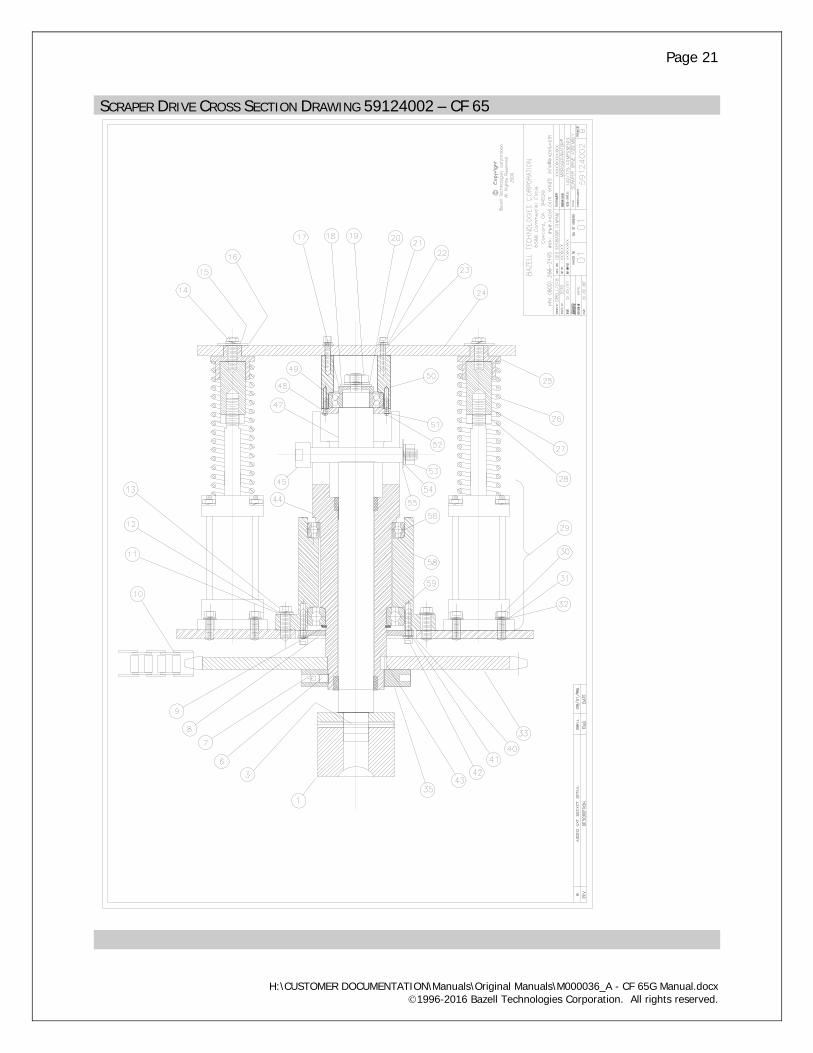
SCRAPER DRIVE CROSS SECTION DRAWING 59124002 – CF 65

Page 22
H:\CUSTOMER DOCUMENTATION\Manuals\Original Manuals\M000036_A - CF 65G Manual.docx 1996-2016 Bazell Technologies Corporation. All rights reserved.
SCRAPER DRIVE ASSEMBLY PARTS LIST DWG 58124002 – CF 65 ITEM QTY PART NO. DESCRIPTION MATERIAL/SPEC
2065400 ASSEMBLY (COMPLETE) 1, 3, 6, 7, 8, 9, 40, 41, 42, 43, 44, 45, 47, 53, 54, 55, 56, 58, 59
1 1 2065402 SOCKET TOOL, 32 MM HARDENED STEEL 3 1 2065402A RETAINING RING POLYEURATHANE 6 2 2100111 ROD COPPER 7 2 8610820 SET SCREW STEEL 8 1 2150430 BEARING COVER STEEL 9 1 9210070 SNAP RING STEEL 10 1 2065713 CHAIN RS-100 11 4 7411000 FLAT WASHER STEEL 12 4 7311000 LOCK WASHER STEEL 13 4 8111030 HEX HEAD CAP SCREW STEEL 14 2 8111030 HEX HEAD CAP SCREW STEEL 15 2 7311000 LOCK WASHER STEEL 16 2 7411000 FLAT WASHER STEEL 17 1 2150423 BEARING SPACER PLATE STEEL 18 1 7412000 FLAT WASHER STEEL 19 1 7221200 NUT STEEL M12 1.75 20 1 7312000 LOCK WASHER STEEL 21 6 8210630 SOCKET HEAD CAP SCREW STEEL 22 6 7310600 LOCK WASHER STEEL 23 6 7410600 FLAT WASHER STEEL 24 1 2065437 CYLINDER SUPPORT BRACKET STEEL 25 2 2065405 SPRING ADAPTER STEEL 26 2 2065406 SPRING STEEL 27 2 2065403 ADAPTER STEEL 28 2 7221400 NUT 304 SS 29 2 6140050 AIR CYLINDER SMC 40-50 PRE-LUBRICATED 30 8 8220625 SOCKET HEAD CAP SCREW STEEL 31 8 7310600 LOCK WASHER STEEL 32 8 7410600 FLAT WASHER STEEL 33 1 2065421 SPROCKET STEEL 35 1 2150428 NUT, ROUND STEEL 40 6 7410600 FLAT WASHER STEEL 41 6 7310600 LOCK WASHER STEEL 42 6 8210625 SOCKET HEAD CAP SCREW STEEL 43 1 3070716 KEY STEEL 44 1 2150436 SPINDLE STEEL 45 1 8721699 SHOULDER BOLT 304 SS 47 1 2100446 SLIDE SHAFT 25MM SQUARE DRIVE STEEL* 48 1 2150424 BEARING COVER STEEL 49 1 1331206 BEARING STEEL 50 1 2150435 BEARING HOUSING STEEL 51 6 7310600 LOCK WASHER STEEL 52 6 8410415 ROUND HEAD CAP SCREW STEEL

Page 23
H:\CUSTOMER DOCUMENTATION\Manuals\Original Manuals\M000036_A - CF 65G Manual.docx 1996-2016 Bazell Technologies Corporation. All rights reserved.
53 1 7221200 NUT STEEL 54 1 7311200 LOCK WASHER STEEL 55 1 7411200 FLAT WASHER STEEL 56 1 1336916 BEARING 6916 58 1 2150432 BEARING HOUSING STEEL 59 1 1336014 BEARING 6014

Page 24
H:\CUSTOMER DOCUMENTATION\Manuals\Original Manuals\M000036_A - CF 65G Manual.docx 1996-2016 Bazell Technologies Corporation. All rights reserved.
STOPPER ASSEMBLY DRAWING #5A125010

Page 25
H:\CUSTOMER DOCUMENTATION\Manuals\Original Manuals\M000036_A - CF 65G Manual.docx 1996-2016 Bazell Technologies Corporation. All rights reserved.
STOPPER ASSEMBLY PARTS LIST - DRAWING #5A125010 ITEM QTY PART NO. DESCRIPTION MATERIAL/
SPECIFICATION 2065500 STOPPER ASSEMBLY COMPLETE
INCLUDES ITEMS 1,2,3,15 &16
1 1 2065501 Stopper Housing, Lower Brass/Carbon Steel
2 1 2065502 Spring 304SS 3 1 2065503 Stopper Shaft 304SS/Carbon
Steel 4 1 8410415 Phillips Head Cap Screw 304SS 5 1 2100520 Stopper Adapter 304SS 6 1 2100521 Lock Nut 304SS 7 1 6140025 Air Cylinder 40 X 25 8 2 8210635 Socket Head Cap Screw Steel 9 2 7410600 Washer Steel 10 1 2100522 Stopper Adapter Flange Steel 11 2 7410600 Washer Steel 12 2 7210600 Nut Steel 13 2 7310600 Lock Washer Steel 14 2 7210600 Nut Steel 15 1 2065515 Stopper Housing, Upper Carbon Steel 16 1 4303112 “O” ring BUNA N
OUTLINE MICROSEPARATOR ON FRAME

Page 26
H:\CUSTOMER DOCUMENTATION\Manuals\Original Manuals\M000036_A - CF 65G Manual.docx 1996-2016 Bazell Technologies Corporation. All rights reserved.
DRAWING# 5A112004
TYPICAL PIPING LAYOUT

Page 27
H:\CUSTOMER DOCUMENTATION\Manuals\Original Manuals\M000036_A - CF 65G Manual.docx 1996-2016 Bazell Technologies Corporation. All rights reserved.
DRAWING# 5A113001

Page 28
H:\CUSTOMER DOCUMENTATION\Manuals\Original Manuals\M000036_A - CF 65G Manual.docx 1996-2016 Bazell Technologies Corporation. All rights reserved.
PNEUMATIC DRAWING# 5A132013

Page 29
H:\CUSTOMER DOCUMENTATION\Manuals\Original Manuals\M000036_A - CF 65G Manual.docx 1996-2016 Bazell Technologies Corporation. All rights reserved.
MAINTENANCE Regular preventative maintenance will help ensure efficient, trouble free service for many years. Emphasis should always be given to proper regulation of flow to and clear passage of flow from the Microseparator. MONTHLY Check the following: 1. Flow rate to machine: measure manually at the end of return piping. Adjust if necessary. 2. Oil supply at the main air regulator. 3. Drive belts for proper tension and wear. 4. Feed timer setting: solids level in feed will change with operating conditions: i.e. production levels, use of filtration equipment, etc. Properly set, the machine will discharge at or near rotor capacity. See Principle of Operation section of manual. 5. Drain cabinet for solids build up: Clean and flush regularly to ensure a free flow of liquid from the drain cabinet. TWO YEARS
Replace: 1. Drive belts 2. Stopper end piece 3. O rings 4. Oil seals 5. Check, and replace if necessary, the bearings. Properly operated, the Microseparator will not require new bearings after two years, but many will find it convenient to replace them at this time. 6. Clean and flush drain cabinet, drain lines and feed lines. Feed valves should also be disassembled and cleaned at this time. Check closely the following: 7. Slide plate pneumatic cylinders and inspect: - seals and fittings - Alignment of cylinder shafts for even operation. Adjust fasteners at the end of the cylinder shaft if necessary. 8. Drive chain tension and adjust if necessary. 9. Alignment of slide shaft socket tool and scraper drive hex nut. This procedure is essential anytime the rotor is removed from machine. Consult Bazell Technologies for proper procedure. 10. Stopper assembly limit switch for proper actuation. Switch should engage immediately upon downward movement of stopper assembly. 11. Inspect air lines and fittings for wear/damage. 12. Inspect vibration switch for proper leveling. Adjust if necessary. 13. Check vibration damper bolts and lag bolts for tightness.

Page 30
H:\CUSTOMER DOCUMENTATION\Manuals\Original Manuals\M000036_A - CF 65G Manual.docx 1996-2016 Bazell Technologies Corporation. All rights reserved.
TROUBLE SHOOTING OBSERVATION ACTION Motor Over-current Check overload settings on starter (separator drive) Be sure rotor can spin freely, turn rotor pulley manually with MAIN CIRCUIT BREAKER OFF. See bearing failure Check overload settings Hardened solids in rotor - contact authorized service center. Vibration Incomplete/improper cleaning cycle increase scraper time settings (TMR-5 and TMR-7) increase total scraper time setting (TMR-3) Check first rotation of scraper drive, should be clockwise looking down Damaged/worn out bearings - contact Service Center Loose anchor bolts Loose drive belts Stopper block sheared off rotor - contact service center Bearing failure Causes for bearing failure: Excessive flow rate to machine Restricted outlet piping, i.e.: - reducers used in outlet piping - end of return piping under water - air traps caused by failure to maintain downward slope for entire pipe length. There cannot be any rises. Normal bearing life exceeded Consistently dirty fluid sump Machine too small for duty - review sizing calculations with dealer Sump agitation not present or not of sufficient capacity to deliver solids to feed pump
Sump agitation not working properly

Page 31
H:\CUSTOMER DOCUMENTATION\Manuals\Original Manuals\M000036_A - CF 65G Manual.docx 1996-2016 Bazell Technologies Corporation. All rights reserved.
ELECTRICAL PRINTS DRAWING # - 58131300 SERIES

Page 32
H:\CUSTOMER DOCUMENTATION\Manuals\Original Manuals\M000036_A - CF 65G Manual.docx 1996-2016 Bazell Technologies Corporation. All rights reserved.
WARRANTY The Microseparator is warranted by Bazell Technologies to the original purchaser against defects in workmanship or materials under normal use (rental use excluded) for one year after date of purchase. Any part that is determined to be defective in material or workmanship and returned to an authorized service location, as Bazell Technologies designates, shipping costs prepaid, will be repaired or replaced at Bazell Technologies option, provided written notice of the alleged defect is received within one year from date of shipment. Excluded from the foregoing guarantee are damages caused by ordinary wear and tear, erosion or corrosion, misuse, abuse, or improper handling by the purchaser or any third party. Bazell Technologies makes no additional warranties, expressed or implied, whether of merchantability, or otherwise, other than stated above. Bazell Technologies shall not be responsible for any indirect, special, or consequential damages, nor for any claim arising out of the sale or use of its equipment, beyond the remedy stated above. Equipment, parts, or accessories manufactured by others carry the guaranty of the manufacturer only. Any warranties or claims which differ from the foregoing are unauthorized by Bazell Technologies and become the warranty solely of the party making them, unless specifically authorized in writing by an officer of Bazell Technologies. Bazell Technologies liability in all events is limited to the purchase price paid. Bazell Technologies will make a good faith effort for prompt correction or other adjustment with respect to any product that proves to be defective within warranty. For any product believed to be defective within warranty, first write or call the dealer from whom the product was purchased. The dealer will give additional directions. If unable to resolve satisfactorily, write to Bazell Technologies at the address below, giving dealers name, address, date and number of dealer’s invoice, and describing the nature of the defect. If the product was damaged in transit, address your claim to the responsible carrier.
Bazell Technologies Corporation 5066 Commercial Circle
Concord, CA. 94520 (800) 288-2465 FAX (925) 603-0901
email: [email protected] web: www.bazell.com
Bazell Technologies reserves the right to change specification without notice. Microseparator and the Microseparator Logo are Registered Trademarks of Bazell Technologies Corporation. CentriClean and MicroCone are trademarks of Bazell Technologies Corporation. All rights reserved.