operations and service manual pinball wizard - brunswick · chlorinite solvent #008 lane stripper...
TRANSCRIPT

Pinball Wizard
Operations and Service Manual
March 2000 / 84-900029-000
Pinball Wizard System Operations and Service Manual
© March 2000 by the Brunswick Bowling and Billiards Corporation. All rights reserved.Past Revisions: September 1999
Reorder Part No. 84-900029-000
Confidential proprietary information. All information contained in this document is subject to change without notice.Do not reproduce or disclose without the written consent of the Brunswick Indoor Recreation Group.
Brunswick Indoor Recreation GroupCapital Equipment Division525 W. Laketon AvenuePost Office Box 329Muskegon, MI 49443-0329U.S.A.
231.725.3300Fax 231.725.3412
Statement of Intent
This manual is provided to be used by qualifiedbowling center personnel. Customer acceptsresponsibility for safety training of all personnelwho service and maintain this product.
i
Table of ContentsWarranty and Service Policy ............................................................................ 1
Replacement Parts Under the Warranty ....................................................... 1Federal Communications Commission Class B Equipment .............................. 2Product Information Sheet ................................................................................ 3
Products Not Harmful to Pinball Wizard Gutters .......................................... 3Brunswick Products ................................................................................... 3DBA Products ........................................................................................... 3Perry-Austen Products .............................................................................. 3
Products Harmful to Pinball Wizard Gutters ................................................. 3Brunswick Products ................................................................................... 3DBA Products ........................................................................................... 3Perry-Austen Products .............................................................................. 3
Safety Precautions ............................................................................................ 4Recommended Guidelines for Safe Automated Bumper Bowling ................... 5
Supervision.................................................................................................... 5Advise ........................................................................................................... 5Use Foul lights and Buzzers .......................................................................... 5Prevent Unnecessary Closings of the Bumpers ............................................ 5
Purpose of This Manual ................................................................................... 6
Section 1: General Information ..................................................................... 7System Overview ............................................................................................. 7
Automated Bumper Controller ...................................................................... 9LEDs.........................................................................................................13Fuses .........................................................................................................13Power Transformer Jumpers (J5 through J8) ...........................................14
System Controller for Stand - Alone Systems ..............................................15
Section 2: Setup and Operations ................................................................. 16Operational Check of System ..........................................................................16Automated Bumper System Operation with Frameworx Scorers -Control Desk ....................................................................................................17
Turn Automated Bumpers On While Issuing a Lane ...................................17Enable Automated Bumpers from the Waiting List .....................................17
At the Waiting List Screen ........................................................................17Turn On Automated Bumpers After Lane Has Been Issued ......................18
Method One ..............................................................................................18Method Two ..............................................................................................18
Turn Off Automated Bumpers While a Lane is in Use ...............................18Method One ..............................................................................................18Method Two ..............................................................................................18
Raising/Resetting Bumpers During an Emergency - Control Desk .............19Operations at Frameworx Scorer ....................................................................20

Automated Bumper System Operation - Frameworx Scorer ......................20Edit Existing Bowler Names at the Scorer ...............................................20
Adding New Bowler Names with Automated Bumpers..............................20System Controller - Initial System Setup - Stand-Alone Configuration ...........21
Lane Configuration Mode - Stand - Alone ...................................................22Confirm Lane Configuration - Stand - Alone ...............................................23Diagnostics Mode - Stand-Alone Controller ................................................24
Daily System Operation- Stand-Alone Configuration ......................................25Individual Lane Selection..............................................................................25Selecting Lane Range ..................................................................................25Error Messages ............................................................................................26Resetting Emergency UP Switch Conditions ...............................................26
Section 3: Service, Maintenance and Troubleshooting ............................ 27Replacing the LLAN PCB (Part Number 57-300790-000) ............................27Cable Replacement ..........................................................................................28
Bumper Rail Position Check ........................................................................31Service and Maintenance ................................................................................34
Periodic Inspections .....................................................................................34Troubleshooting................................................................................................35
Appendix A - Cables ...................................................................................... 38
ii
Pinball Wizard System Operations and Service Manual 1
Warranty and Service PolicyIf any defects in material or workmanship appear during the first three monthsafter installation, the defective part will be repaired or replaced, at Brunswick’soption, with no charge to the Customer.
If any defects in material appear during the nine months following the initial threemonth warranty period, the defective part will be repaired or replaced, atBrunswick’s option, with no charge to the Customer for parts. The Customermust assume all other costs in making the repair or replacement.
All service calls during the first three months of the warranty period, resultingfrom the inability of the Customer’s mechanics to perform required adjustmentsor maintenance, will be billed directly to the Customer.
Brunswick reserves the right to change the design of any product, but assumesno responsibility to incorporate such design changes on products already sold.
The warranty applies only to new products installed by Brunswick and extendsonly to the original purchaser. Repairs or replacements made by anyone notapproved by Brunswick void the warranty.
Under no circumstances shall the Seller or Manufacturer be liable for loss ofprofits or other direct or indirect costs, expenses, losses, or damages arising outof defects in or failure of parts.
Replacement Parts Under the Warranty
All service parts are F.O.B. the installation site both during and after the war-ranty period. The price of parts includes delivery by standard means, such asUnited Parcel Service (UPS). Any expense resulting from expedited delivery,such as air freight, will be billed to the Customer.
During the one year period, parts which are faulty due to material or workman-ship will be replaced or repaired free of charge only if the old part is properlyidentified and turned in for credit. Identify the defective part by attaching a tagcontaining the part name and part number. Light bulbs are not covered by thewarranty.
Contact the Warranty Department at 1-231-725-3433.
2 Pinball Wizard System Operations and Service Manual
Federal Communications Commission Class B Equipment
This equipment has been tested and found to comply with the limits for a class Bdigital device, pursuant to part 15 of the FCC rules. These limits are designed toprovide reasonable protection against harmful interference in a residentialinstallation. This equipment generates, uses and can radiate radio frequencyenergy and, if not installed and used in accordance with the instructions, maycause harmful interference to radio communications. However, there is noguarantee that interference will not occur in a particular installation. If thisequipment does cause harmful interference to radio or television reception, whichcan be determined by turning the equipment off and on , the user is encouragedto try to correct the interference by one or more of the following measures:
• Reorient or relocate the receiving antenna.
• Increase the separation between the equipment and receiver.
• Connect the equipment into an outlet on a circuit different from that towhich the receiver is connected.
• Consult the dealer or an experienced radio/TV technician for help.
Pinball Wizard System Operations and Service Manual 3
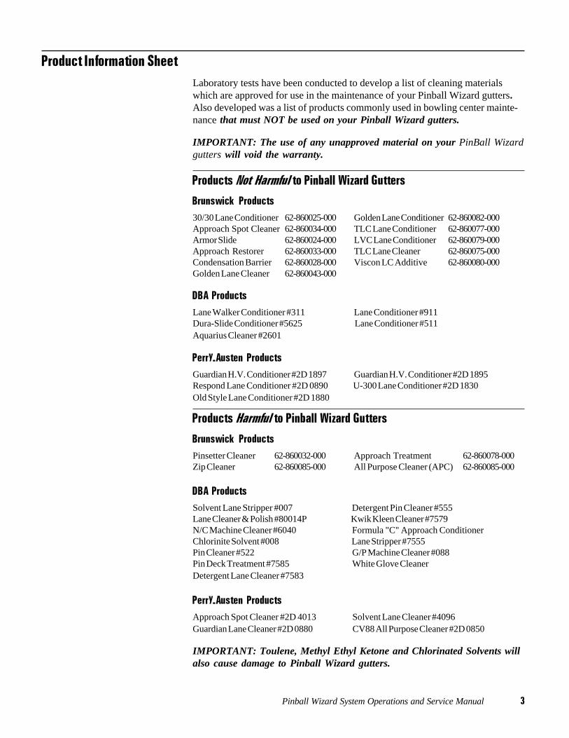
Product Information SheetLaboratory tests have been conducted to develop a list of cleaning materialswhich are approved for use in the maintenance of your Pinball Wizard gutters.Also developed was a list of products commonly used in bowling center mainte-nance that must NOT be used on your Pinball Wizard gutters.
IMPORTANT: The use of any unapproved material on your PinBall Wizardgutters will void the warranty.
Products Not Harmful to Pinball Wizard Gutters
Brunswick Products30/30 Lane Conditioner62-860025-000 Golden Lane Conditioner62-860082-000Approach Spot Cleaner62-860034-000 TLC Lane Conditioner 62-860077-000Armor Slide 62-860024-000 LVC Lane Conditioner 62-860079-000Approach Restorer 62-860033-000 TLC Lane Cleaner 62-860075-000Condensation Barrier 62-860028-000 Viscon LC Additive 62-860080-000Golden Lane Cleaner 62-860043-000
DBA ProductsLane Walker Conditioner #311 Lane Conditioner #911Dura-Slide Conditioner #5625 Lane Conditioner #511Aquarius Cleaner #2601
Perry-Austen ProductsGuardian H.V. Conditioner #2D 1897 Guardian H.V. Conditioner #2D 1895Respond Lane Conditioner #2D 0890 U-300 Lane Conditioner #2D 1830Old Style Lane Conditioner #2D 1880
Products Harmful to Pinball Wizard Gutters
Brunswick ProductsPinsetter Cleaner 62-860032-000 Approach Treatment 62-860078-000Zip Cleaner 62-860085-000 All Purpose Cleaner (APC)62-860085-000
DBA ProductsSolvent Lane Stripper #007 Detergent Pin Cleaner #555Lane Cleaner & Polish #80014P Kwik Kleen Cleaner #7579N/C Machine Cleaner #6040 Formula "C" Approach ConditionerChlorinite Solvent #008 Lane Stripper #7555Pin Cleaner #522 G/P Machine Cleaner #088Pin Deck Treatment #7585 White Glove CleanerDetergent Lane Cleaner #7583
Perry-Austen ProductsApproach Spot Cleaner #2D 4013 Solvent Lane Cleaner #4096Guardian Lane Cleaner #2D 0880 CV88 All Purpose Cleaner #2D 0850
IMPORTANT: Toulene, Methyl Ethyl Ketone and Chlorinated Solvents willalso cause damage to Pinball Wizard gutters.
4 Pinball Wizard System Operations and Service Manual
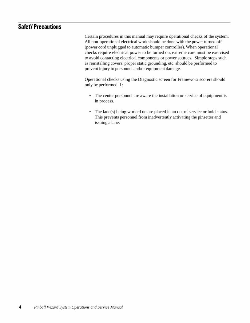
Safety PrecautionsCertain procedures in this manual may require operational checks of the system.All non-operational electrical work should be done with the power turned off(power cord unplugged to automatic bumper controller). When operationalchecks require electrical power to be turned on, extreme care must be exercisedto avoid contacting electrical components or power sources. Simple steps suchas reinstalling covers, proper static grounding, etc. should be performed toprevent injury to personnel and/or equipment damage.
Operational checks using the Diagnostic screen for Frameworx scorers shouldonly be performed if :
• The center personnel are aware the installation or service of equipment isin process.
• The lane(s) being worked on are placed in an out of service or hold status.This prevents personnel from inadvertently activating the pinsetter andissuing a lane.
Pinball Wizard System Operations and Service Manual 5
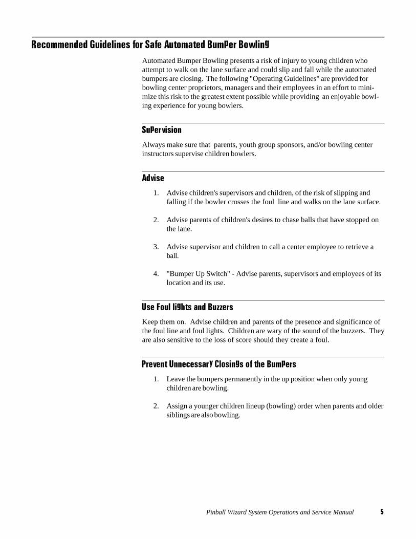
Recommended Guidelines for Safe Automated Bumper BowlingAutomated Bumper Bowling presents a risk of injury to young children whoattempt to walk on the lane surface and could slip and fall while the automatedbumpers are closing. The following "Operating Guidelines" are provided forbowling center proprietors, managers and their employees in an effort to mini-mize this risk to the greatest extent possible while providing an enjoyable bowl-ing experience for young bowlers.
Supervision
Always make sure that parents, youth group sponsors, and/or bowling centerinstructors supervise children bowlers.
Advise
1. Advise children's supervisors and children, of the risk of slipping andfalling if the bowler crosses the foul line and walks on the lane surface.
2. Advise parents of children's desires to chase balls that have stopped onthe lane.
3. Advise supervisor and children to call a center employee to retrieve aball.
4. "Bumper Up Switch" - Advise parents, supervisors and employees of itslocation and its use.
Use Foul lights and Buzzers
Keep them on. Advise children and parents of the presence and significance ofthe foul line and foul lights. Children are wary of the sound of the buzzers. Theyare also sensitive to the loss of score should they create a foul.
Prevent Unnecessary Closings of the Bumpers
1. Leave the bumpers permanently in the up position when only youngchildren are bowling.
2. Assign a younger children lineup (bowling) order when parents and oldersiblings are also bowling.
6 Pinball Wizard System Operations and Service Manual
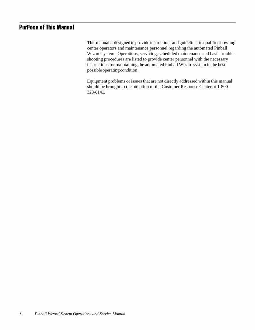
Purpose of This Manual
This manual is designed to provide instructions and guidelines to qualified bowlingcenter operators and maintenance personnel regarding the automated PinballWizard system. Operations, servicing, scheduled maintenance and basic trouble-shooting procedures are listed to provide center personnel with the necessaryinstructions for maintaining the automated Pinball Wizard system in the bestpossible operating condition.
Equipment problems or issues that are not directly addressed within this manualshould be brought to the attention of the Customer Response Center at 1-800-323-8141.
Pinball Wizard System Operations and Service Manual 7
Section 1: General Information
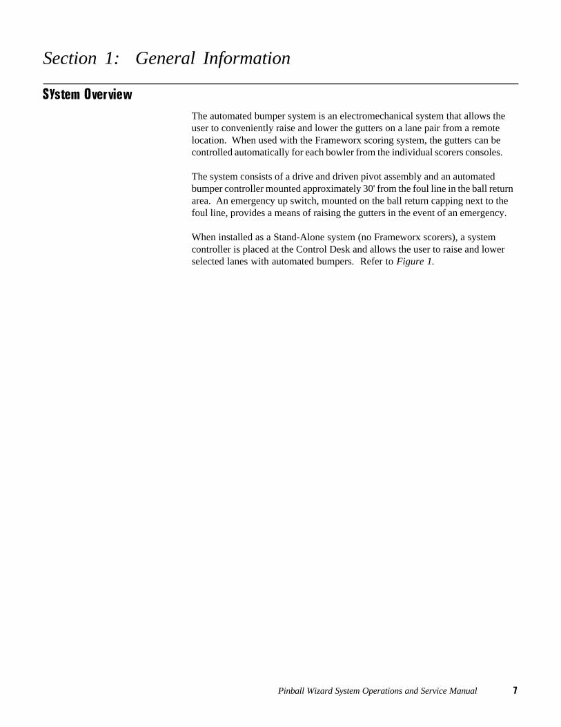
System OverviewThe automated bumper system is an electromechanical system that allows theuser to conveniently raise and lower the gutters on a lane pair from a remotelocation. When used with the Frameworx scoring system, the gutters can becontrolled automatically for each bowler from the individual scorers consoles.
The system consists of a drive and driven pivot assembly and an automatedbumper controller mounted approximately 30' from the foul line in the ball returnarea. An emergency up switch, mounted on the ball return capping next to thefoul line, provides a means of raising the gutters in the event of an emergency.
When installed as a Stand-Alone system (no Frameworx scorers), a systemcontroller is placed at the Control Desk and allows the user to raise and lowerselected lanes with automated bumpers. Refer to Figure 1.
8 Pinball Wizard System Operations and Service Manual
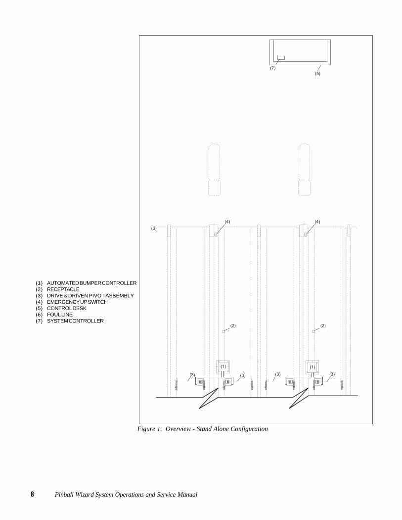
(1) AUTOMATED BUMPER CONTROLLER(2) RECEPTACLE(3) DRIVE & DRIVEN PIVOT ASSEMBLY(4) EMERGENCY UP SWITCH(5) CONTROL DESK(6) FOUL LINE(7) SYSTEM CONTROLLER
Figure 1. Overview - Stand Alone Configuration
Pinball Wizard System Operations and Service Manual 9
Automated Bumper Controller
Commonly referred to as the control “Box”, the automated bumper controllerconsists of a single printed circuit board (PCB). The main function of this PCB isto supply and control power to the actuator motors of the lane pair.
The PCB determines when to raise or lower the gutters based on information itreceives from the control desk's System Controller (Stand-Alone installations) orI/O PCB (Frameworx scorer installations).
The emergency up switch mounted on the ball return capping, overrides anyinformation received from the System Controller or I/O PCB causing the auto-mated bumper controller to raise the gutters. Refer to Figure 2.
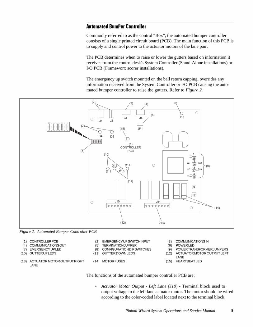
Figure 2. Automated Bumper Controller PCB
(1) CONTROLLER PCB (2) EMERGENCY UP SWITCH INPUT (3) COMMUNICATIONS IN(4) COMMUNICATIONS OUT (5) TERMINATION JUMPER (6) POWER LED(7) EMERGENCY UP LED (8) CONFIGURATION DIP SWITCHES (9) POWER TRANSFORMER JUMPERS
(10) GUTTER UP LEDS (11) GUTTER DOWN LEDS (12) ACTUATOR MOTOR OUTPUT LEFTLANE
(13) ACTUATOR MOTOR OUTPUT RIGHT (14) MOTOR FUSES (15) HEARTBEAT LEDLANE
The functions of the automated bumper controller PCB are:
• Actuator Motor Output - Left Lane (J10) - Terminal block used tooutput voltage to the left lane actuator motor. The motor should be wiredaccording to the color-coded label located next to the terminal block.
10 Pinball Wizard System Operations and Service Manual
• Actuator Motor Output - Right Lane (J11) - Terminal block used tooutput voltage to the right lane actuator motor. The motor should bewired according to the color-coded label located next to the terminalblock.
• Communication In (J3) - Input for communication entering the PCB.On the first lane pair for Stand-Alone configurations, this informationcomes from the system controller located at the control desk.Refer to Figure 2. For additional lane pairs in a Stand-Alone system thecable comes from the prior lane pair bumper controller. Refer toCommunications Out (J4). For installations with Frameworx scorers,the input data to J3 is sent from the I/O PCB - J2.
NOTE: A LLAN Breakout PCB is mounted in either the lane group proces-sor, or Frameworx scorer console, and allows easy cabling to the existingFrameworx local LAN.
• Communication Out (J4) - This connection allows the informationentering the PCB at J3 to continue out of the PCB to other devices. Forstand alone systems, the J4 port attaches to the next lane pair’s auto-mated bumper controller. If automated bumper controller is for the lastlane pair with automated bumpers, a jumper (terminator) must beinstalled on pins 2 and 3 of JP1. Refer to Figure 3.
• Emergency Up Switch Connectors (J1 and J2) - When activated, theemergency up switch for that specific lane pair, triggers the controllerPCB and overrides any current command or condition to immediatelyraise the gutters on both lanes. J1 port is for left lane gutters and J2 isfor right lane gutters.
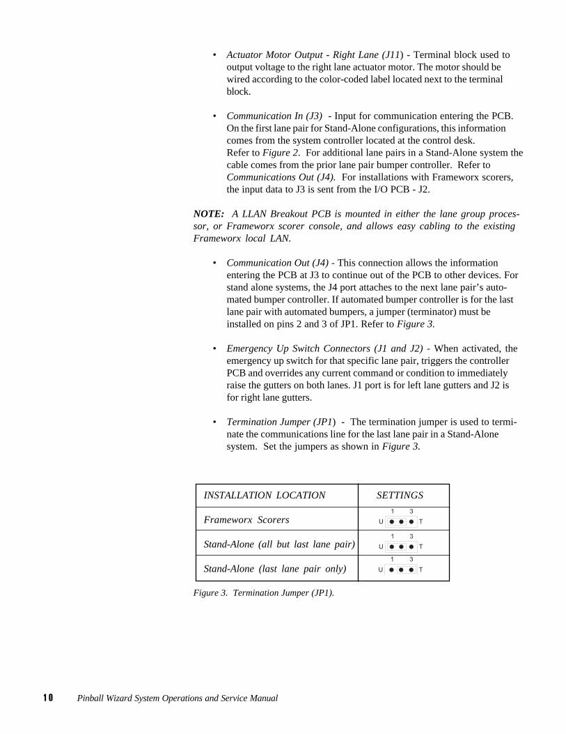
• Termination Jumper (JP1) - The termination jumper is used to termi-nate the communications line for the last lane pair in a Stand-Alonesystem. Set the jumpers as shown in Figure 3.
INSTALLATION LOCATION SETTINGS
Frameworx Scorers
Stand-Alone (all but last lane pair)
Stand-Alone (last lane pair only)
Figure 3. Termination Jumper (JP1).

Pinball Wizard System Operations and Service Manual 11
• DIP Switch Configuration - These two-position ON-OFF switchesprovide lane address identification to the controller PCB. When Frame-worx scorers are installed, ALL DIP switches must be set to OFF. ForStand-Alone systems, the DIP switches MUST be set as listed inFigure 4.

12 Pinball Wizard System Operations and Service Manual
Lane No. SW 1 SW 2 SW 3 SW 4 SW 5 SW 6 SW 7 SW 8
1-2 ON OFF OFF OFF OFF OFF OFF OFF
3-4 ON ON OFF OFF OFF OFF OFF OFF
5-6 ON OFF ON OFF OFF OFF OFF OFF
7-8 ON ON ON OFF OFF OFF OFF OFF
9-10 ON OFF OFF ON OFF OFF OFF OFF
11-12 ON ON OFF ON OFF OFF OFF OFF
13-14 ON OFF ON ON OFF OFF OFF OFF
15-16 ON ON ON ON OFF OFF OFF OFF
17-18 ON OFF OFF OFF ON OFF OFF OFF
19-20 ON ON OFF OFF ON OFF OFF OFF
21-22 ON OFF ON OFF ON OFF OFF OFF
23-24 ON ON ON OFF ON OFF OFF OFF
25-26 ON OFF OFF ON ON OFF OFF OFF
27-28 ON ON OFF ON ON OFF OFF OFF
29-30 ON OFF ON ON ON OFF OFF OFF
31-32 ON ON ON ON ON OFF OFF OFF
33-34 ON OFF OFF OFF OFF ON OFF OFF
35-36 ON ON OFF OFF OFF ON OFF OFF
37-38 ON OFF ON OFF OFF ON OFF OFF
39-40 ON ON ON OFF OFF ON OFF OFF
41-42 ON OFF OFF ON OFF ON OFF OFF
43-44 ON ON OFF ON OFF ON OFF OFF
45-46 ON OFF ON ON OFF ON OFF OFF
47-48 ON ON ON ON OFF ON OFF OFF
49-50 ON OFF OFF OFF ON ON OFF OFF
51-52 ON ON OFF OFF ON ON OFF OFF
53-54 ON OFF ON OFF ON ON OFF OFF
55-56 ON ON ON OFF ON ON OFF OFF
57-58 ON OFF OFF ON ON ON OFF OFF
59-60 ON ON OFF ON ON ON OFF OFF
61-62 ON OFF ON ON ON ON OFF OFF
63-64 ON ON ON ON ON ON OFF OFF
65-66 ON OFF OFF OFF OFF OFF ON OFF
67-68 ON ON OFF OFF OFF OFF ON OFF
69-70 ON OFF ON OFF OFF OFF ON OFF
71-72 ON ON ON OFF OFF OFF ON OFF
73-74 ON OFF OFF ON OFF OFF ON OFF
75-76 ON ON OFF ON OFF OFF ON OFF
77-78 ON OFF ON ON OFF OFF ON OFF
79-80 ON ON ON ON OFF OFF ON OFF
NOTE: For installations withFrameworx scorers all switchesmust be "OFF".
Figure 4. DIP Switch Settings (Stand - Alone)
Pinball Wizard System Operations and Service Manual 13
LEDs
Several LEDs are located on the controller PCB to indicate various operatingfunctions/conditions. Refer to Figure 2 for LED locations on the controller PCB.The LED functions are:
• Gutter Up LEDs (D11, D13) - These LEDs light to indicate that thegutters are in the UP position. LED D11 is for left lane and D13 is forright lane gutters.
• Gutter Down LEDs (D12, D14) - These LEDs light to indicate that thegutters are in the DOWN position. LED D12 is for left lane and D14 isfor right lane gutters.
• Emergency UP LEDs (D4, D5) - These LEDs light whenever theemergency up switch is used to raise the gutters.
• Power LED (D3) - This LED lights to indicate the presence of DC 12Vpower.
• Heartbeat LED (D10) - This LED flashes to indicate the presence ofcommunication to the Frameworx scorer or the system controller in astand alone system. When communication is present, the LED will lightin a FLASH, FLASH, PAUSE sequence.
Fuses
There are three fuses located on the controller PCB. Refer to Figure 2.
• Power Fuse - A .25 amp main power fuse.
• Motor Fuses - Fuses for the actuator motors. Fuses are field installedduring installation based on input voltage. 115VAC = 1.6 amp,230VAC= .8 amp
NOTE: Fuse F2 is for right lane actuator motor and F3 is for left laneactuator motor.
14 Pinball Wizard System Operations and Service Manual
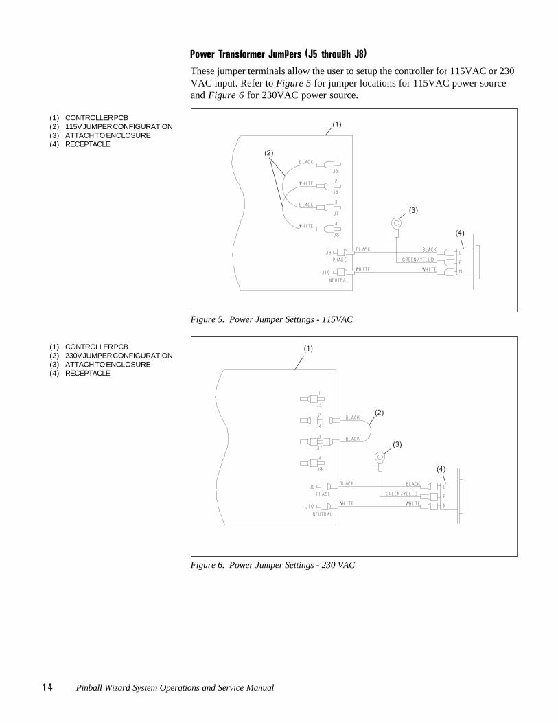
Power Transformer Jumpers (J5 through J8)
These jumper terminals allow the user to setup the controller for 115VAC or 230VAC input. Refer to Figure 5 for jumper locations for 115VAC power sourceand Figure 6 for 230VAC power source.
(1) CONTROLLER PCB(2) 115V JUMPER CONFIGURATION(3) ATTACH TO ENCLOSURE(4) RECEPTACLE
Figure 5. Power Jumper Settings - 115VAC
(1) CONTROLLER PCB(2) 230V JUMPER CONFIGURATION(3) ATTACH TO ENCLOSURE(4) RECEPTACLE
Figure 6. Power Jumper Settings - 230 VAC
Pinball Wizard System Operations and Service Manual 15
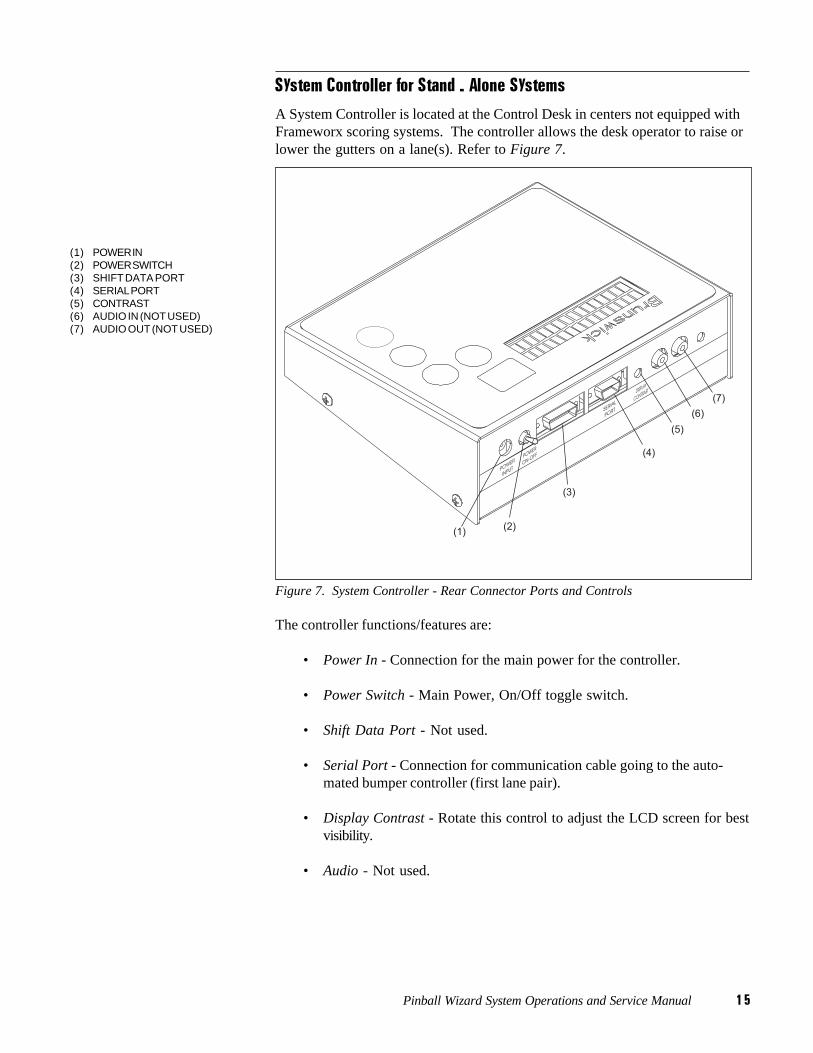
System Controller for Stand - Alone Systems
A System Controller is located at the Control Desk in centers not equipped withFrameworx scoring systems. The controller allows the desk operator to raise orlower the gutters on a lane(s). Refer to Figure 7.
(1) POWER IN(2) POWER SWITCH(3) SHIFT DATA PORT(4) SERIAL PORT(5) CONTRAST(6) AUDIO IN (NOT USED)(7) AUDIO OUT (NOT USED)
Figure 7. System Controller - Rear Connector Ports and Controls
The controller functions/features are:
• Power In - Connection for the main power for the controller.
• Power Switch - Main Power, On/Off toggle switch.
• Shift Data Port - Not used.
• Serial Port - Connection for communication cable going to the auto-mated bumper controller (first lane pair).
• Display Contrast - Rotate this control to adjust the LCD screen for bestvisibility.
• Audio - Not used.
16 Pinball Wizard System Operations and Service Manual
Section 2: Setup and Operations
Operational Check of SystemNOTE: The following steps are performed at the Frameworx scorer andrequire Frameworx Scorer software version 4.0 or higher. They are basiccommands and/or status messages used to verify system operation afterinstallation or during system troubleshooting. General bumper systemoperation is listed under the "Automated Bumper - Control Desk".
1. Choose the "Select Diagnostics Function" menu, enter password andpress OK.
2. Select "Bumpers Configuration" and press OK.
3. Choose "Left Lane or Right Lane Configuration" and press OK.
4. Select "Enable Bumpers" and press OK.
5. Scroll down to the "Close Channels" option and press OK. The guttersshould close.
NOTE: Reset switch status before each check.
6. Scroll down to "Open Channels" and press OK. The gutters shouldopen.
7. Repeat steps 3-6 for other lane pair.
8. Press CANCEL to return to Frameworx scorer screen.
Pinball Wizard System Operations and Service Manual 17
Automated Bumper System Operation with Frameworx Scorers - Control Desk
Turn On Automated Bumpers While Issuing a Lane
NOTE: Perform the following steps at the Control Desk CMS terminal:
1. Select LANE NUMBER(S) for automated bumper system.
2. Press LANE ON key.
3. While "check in" screen is displayed, press the é key. The automatedbumper system is now available to the bowlers on that lane. Press the éa second time to disable automated bumpers.
NOTE: The status of the automated bumpers is displayed by a “W” in theRATE box while the "check in" screen is displayed. When the letter “W” ispresent, automated bumpers are available to the bowlers on the selectedlane or lane range. Automated bumpers will need to be enabled for theappropriate bowlers as names are entered at the automatic scorer. Namesthat were previously entered, entered via the Waiting List, entered via“Download Open Party” or entered via “View/Correct Scores” will have tobe edited at the automatic scorer to activate for the appropriate bowler(s).
Enable Automated Bumpers from the Waiting List
At the Waiting List Screen
1. Press "A" to add a party to the waiting list.
2. Type the party name and press ENTER.
3. Type the number of bowlers in the party and press ENTER.
4. Use the arrow keys to highlight the scoring unit available and pressENTER.
5. Use the arrow keys to highlight "Bumpers" on the on the CentersServices List. Press ENTER to select bumpers. (An asterisk willdisplay when bumpers are selected.) Pressing ENTER a second timedeselects bumpers. Press ENTER SCREEN when all of the desiredCenter Services have been selected.
6. Proceed with step 6 as listed in the Control Desk Operations Guide57-900355-000, pages 3-2 through 3-3.

18 Pinball Wizard System Operations and Service Manual
Turn On Automated Bumpers After Lane Has Been Issued
NOTE: Operators can choose one of two methods to turn on the auto-mated bumpers after a lane has been issued.
Method One
1. Press SCORER STATUS key.
2. Enter the lane number and/or lane range and press the é key.
3. The prompt “Lift bumpers for everyone? Y/N” will appear.
4. If Y (yes) is selected, ALL bowler names for that lane number/lanerange will have automated bumpers activated.
5. If N (no) is selected, the appropriate bowler name(s) will have to beedited at the scorer.
Method Two
1. Enter lane number(s) and press ADJUST key.
2. With "ADJUST" screen displayed, press é key. Bumpers are nowavailable for bowler(s) on this lane.
3. Press ADJUST key again to exit.
Turn Off Automated Bumpers While a Lane is in Use
NOTE: Operators can choose one of two methods to turn off the auto-mated bumpers while a lane is in use.
Method One
1. To disable the automated bumper system:
a. Enter the lane number or lane range.
b. Press U key and then the é key. Automated bumpers are no longeravailable for that lane/lane range.
Method Two
1. Enter lane number(s) and press "ADJUST" key.
2. With adjust screen displayed, press the é key. Bumpers are no longeravailable for bowler(s) on this lane.
3. Press adjust key again to exit.

Pinball Wizard System Operations and Service Manual 19
Raising/Resetting Bumpers During an Emergency - Control Desk
1. EMERGENCY UP - Enter lane number or lane range and press é key.
2. To reset bumpers after an Emergency UP command has been given ORthe Emergency UP switch has been pressed:
a. Enter lane number or lane range and press é key.
b. At the prompt, “Bumpers are in emergency up. Do you want to turnoff emergency up? Y/N". Enter Y to lower bumpers and return tonormal operation. If N is entered, bumpers will remain in the emer-gency UP position.
20 Pinball Wizard System Operations and Service Manual
Operations at Frameworx Scorer
Automated Bumper System Operation - Frameworx Scorer
Edit Existing Bowler Names at the Scorer
1. Press BOWLER and then EDIT.
2. Use the é and ê keys to highlight bowler name to be edited and pressOK.
3. Press the é or ê key to highlight AUTOMATED BUMPERS mode.
4. Use ç or è key to turn bumper on or off for that bowler. Press OKwhen finished.
Adding New Bowler Names with Automated Bumpers
1. Press BOWLER and then ADD.
2. Enter bowler name and press ê key.
3. Use ç or è to select left or right-handed coach display and then pressê key.
4. Use ç or è key to select (turn on) automated bumpers for specifiedbowler name.
5. Press DONE or NEXT to add another bowler with automated bumpers.

Pinball Wizard System Operations and Service Manual 21
System Controller - Initial System Setup - Stand Alone ConfigurationAfter completing the installation of automated bumper system components, thesystem controller at the control desk must be programmed to specify which andhow many lanes within the center have automated bumpers installed.
Perform the following steps:
1. Place toggle switch on rear of unit up (ON) position. Refer to Figure 8for switch/button locations.
Figure 8. System Controller - Stand Alone Configuration
(1) SELECT "ENTER" KEY (2) LANE NUMBER SCROLL DOWN KEY (3) "NO" KEY (AUTOMATED BUMPERSINSTALLED?)
(4) LANE NUMBER SCROLL UP KEY (5) "YES" KEY (AUTOMATED BUMPERS (6) RAISE CHANNEL KEYINSTALLED?)
(7) LOWER CHANNEL KEY
22 Pinball Wizard System Operations and Service Manual
2. On the LCD display, the prompt, “ENTER FIRST LANE WITHAUTOMATED BUMPERS: 01” will appear.
3. Use the4(up) arrow key to identify the first lane number with auto-mated bumpers installed.
4. Press SELECT key. The last lane prompt is now displayed.
5. Use the4(up) and 3 (down) arrow keys to identify the last lanenumber with automated bumpers installed.
6. Press SELECT to accept the lane number data.
Lane Configuration Mode - Stand - Alone
NOTE: It is initially assumed that all lanes from the start to the end lanewill have the automated bumpers installed - all lanes will be set to “Y” (YES- automated bumpers installed). If this is the case, pressing SELECT willend the lane configuration mode immediately.
Those lanes that do NOT have automated bumpers must be identified as follows:
7. With the prompt “ AUTOMATED BUMPERS LN 00? -Y PRESSSELECT TO END” displayed,
a. Use the4(up) and3(down) arrow keys to scroll through the lanenumbers.
b. Press SELECT when desired lane appears.
c. Press4(yes) or3(no) key to identify each specific lane.
d. To change from a no automated bumpers installed status back toyes (automated bumpers installed), press the4key.
e. Press SELECT to end the lane configuration mode.
Pinball Wizard System Operations and Service Manual 23
Confirm Lane Configuration - Stand - Alone
To verify that the lane configuration data has been entered correctly, the follow-ing prompt will appear:
“SETUP COMPLETE? UP = YES DOWN=NO”
1. Press4(YES) key to confirm that the setup is complete; the normal(default) mode is then displayed on the LCD.
2. If3(NO) is pressed, ALL setup data is cleared, and the setup will startover again with the prompt ‘ENTER FIRST LANE WITH AUTOMATEDBUMPERS: 01."
NOTE: If the setup data is corrupted or lost, it will be cleared and theinitial setup prompts will be displayed again. The operator MUST performthe steps listed under “System Controller - Initial System Setup” again.In addition, the operator may change current configuration of lane (i.e.add/remove bumper mode) using same steps.
24 Pinball Wizard System Operations and Service Manual
Diagnostics Mode - Stand - Alone Controller
The diagnostics mode is designed to allow automated bumpers system installersand/or field service personnel to make adjustments and check status of switch onthe drive pivot assembly. Only one lane at a time is affected under the diagnosticsmode.
1. Press and hold SELECT key for five seconds to access the diagnosticsmode.
2. The currently selected lane is displayed:
"DIAG LN01 COARSE*OPEN = 0 CLOSE = 1"
3. Press4key to scroll lane number up or3key to scroll lane number down.Lane numbers without automated bumpers installed are automaticallyskipped.
4. Press SELECT key to toggle between full open/close, coarse and fineadjustment modes.
5. Press5arrow key and continue to press and release to move channel UPin the selected increments.
6. Press6key and press repeatedly to move channel DOWN in the selectedincrements.
NOTE: While in diagnostics mode, the opening and closing status messagesare not displayed.
7. Press and hold the SELECT key for five seconds to disable and exit thediagnostics mode.
Pinball Wizard System Operations and Service Manual 25
Daily System Operation - Stand-Alone ConfigurationInitially, the default lane will be the first lane in the center that has automatedbumpers installed and the following prompt is displayed:
“AUTOMATED BUMPERS LANE O1”
Individual Lane Selection
1. Press8key to scroll up orwto scroll down until desired lane number isdisplayed.
2. Press5arrow key to raise channels (bumpers) for specified lane. Press6key to lower channels for specified lane.
Selecting Lane Range
1. With prompt “AUTOMATED BUMPERS O1” displayed, pressSELECT key. Two up arrows are shown on LCD display beneathstarting lane number.
2. Use8key to scroll up until desired starting lane is displayed.
3. Press SELECT key again to specify the ending lane number. Twoarrows are displayed beneath the current (ending) lane number.
4. Press8or w keys to scroll up or down until desired ending lane isdisplayed.
5. Press5key to raise channels for selected lane range. Press 6key tolower channels for selected lane range.
NOTE: Starting lane range may never be less than the first lane in thecenter that has automated bumpers installed and ending lane range notgreater than last lane with automated bumpers. Pressing and holding eitherthe 56 keys for more than 0.5 seconds will scroll the starting lane lumberat a rate of 1 lane every 0.5 seconds until the maximum or minimum lanehas been reached. Pressing the SELECT key a third time will return to thedefault prompt allowing the operator to select one lane at a time.
Lanes that do NOT have automated bumpers installed are automaticallyskipped over when selecting lane range.
If a selected range of lanes includes lanes that are not all in the same state(opened or closed), pressing the5key will raise all channels that are notcurrently raised. Pressing the6key will lower all channels that are notcurrently lowered.
26 Pinball Wizard System Operations and Service Manual
Daily System Operation - Stand-Alone Configuration - Continued
Error Messages
There are five error messages that may appear on the LCD display;
• Could not open channel• Could not close channel• Communication error• Invalid Switch State• COM LINE DOWN - (All communication with ALL automated bumper
controllers has been lost)
These messages appear to alert the operator of the displayed condition. Refer to“Troubleshooting” section at the rear of this manual for error descriptions andcorrective action.
Resetting Emergency UP Switch Conditions
When the emergency UP switch is pressed on any of the lanes, it overrides anycommands from the system controller and immediately opens the channels on theaffected lane. The following prompt appears on the controller LCD display:
“EMERGENCY UP 01PRESS SEL TO CLR”
1. Press SELECT key to reset an emergency UP condition. Normalautomated bumper operation is restored on the affected lane.
Pinball Wizard System Operations and Service Manual 27
Section 3: Service, Maintenance and Troubleshooting
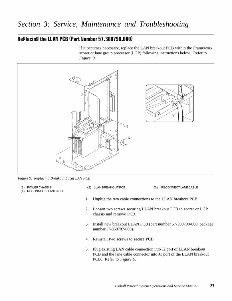
Replacing the LLAN PCB (Part Number 57-300790-000)If it becomes necessary, replace the LAN breakout PCB within the Frameworxscorer or lane group processor (LGP) following instructions below. Refer toFigure 9.
Figure 9. Replacing Breakout Local LAN PCB
(1) POWER CHASSIS (2) LLAN BREAKOUT PCB (3) RECONNECT LANE CABLE(4) RECONNECT LLAN CABLE
1. Unplug the two cable connections to the LLAN breakout PCB.
2. Loosen two screws securing LLAN breakout PCB to scorer or LGPchassis and remove PCB.
3. Install new breakout LLAN PCB (part number 57-300790-000, packagenumber 17-860787-000).
4. Reinstall two screws to secure PCB.
5. Plug existing LAN cable connection into J2 port of LLAN breakoutPCB and the lane cable connector into J1 port of the LLAN breakoutPCB. Refer to Figure 9.
28 Pinball Wizard System Operations and Service Manual
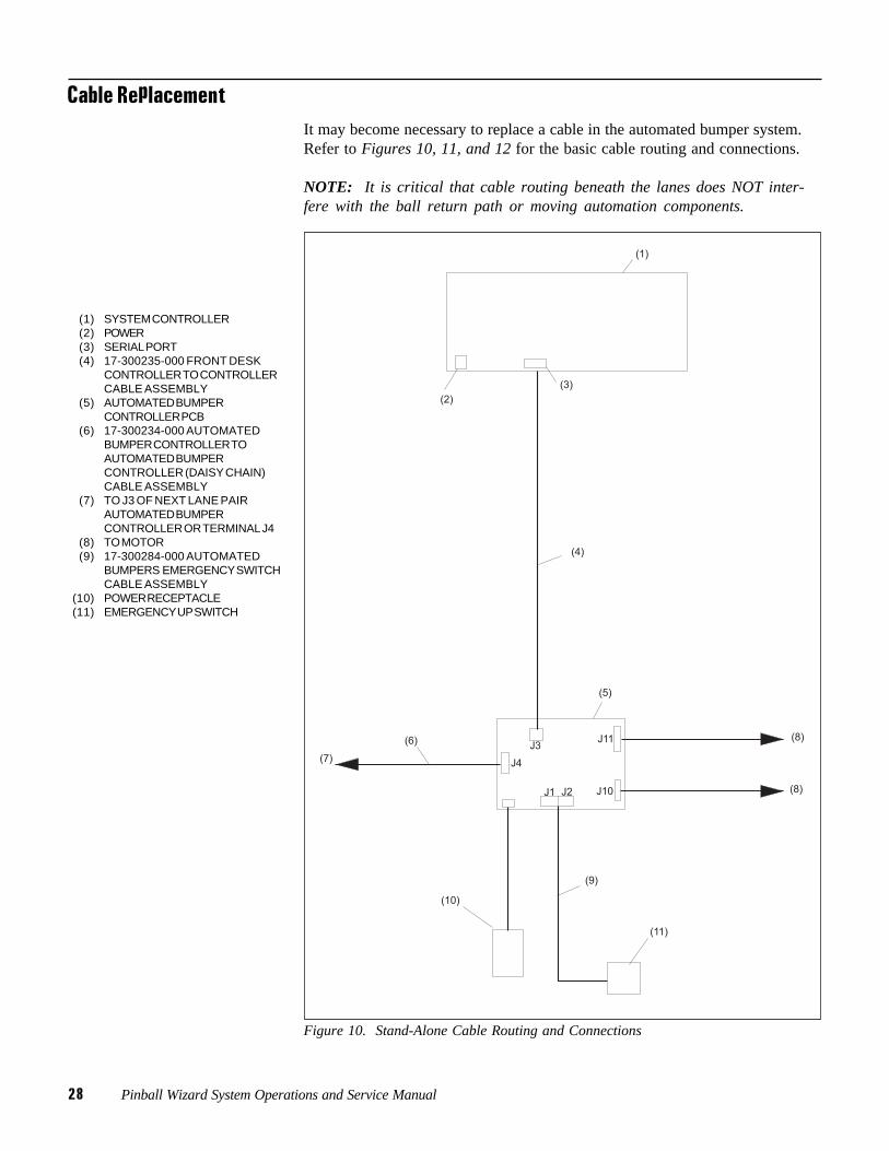
Cable ReplacementIt may become necessary to replace a cable in the automated bumper system.Refer to Figures 10, 11, and 12 for the basic cable routing and connections.
NOTE: It is critical that cable routing beneath the lanes does NOT inter-fere with the ball return path or moving automation components.
(1) SYSTEM CONTROLLER(2) POWER(3) SERIAL PORT(4) 17-300235-000 FRONT DESK
CONTROLLER TO CONTROLLERCABLE ASSEMBLY
(5) AUTOMATED BUMPERCONTROLLER PCB
(6) 17-300234-000 AUTOMATEDBUMPER CONTROLLER TOAUTOMATED BUMPERCONTROLLER (DAISY CHAIN)CABLE ASSEMBLY
(7) TO J3 OF NEXT LANE PAIRAUTOMATED BUMPERCONTROLLER OR TERMINAL J4
(8) TO MOTOR(9) 17-300284-000 AUTOMATED
BUMPERS EMERGENCY SWITCHCABLE ASSEMBLY
(10) POWER RECEPTACLE(11) EMERGENCY UP SWITCH
Figure 10. Stand-Alone Cable Routing and Connections
Pinball Wizard System Operations and Service Manual 29
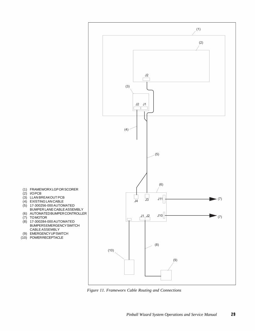
(1) FRAMEWORX LGP OR SCORER(2) I/O PCB(3) LLAN BREAKOUT PCB(4) EXISTING LAN CABLE(5) 17-300256-000 AUTOMATED
BUMPER LANE CABLE ASSEMBLY(6) AUTOMATED BUMPER CONTROLLER(7) TO MOTOR(8) 17-300284-000 AUTOMATED
BUMPERS EMERGENCY SWITCHCABLE ASSEMBLY
(9) EMERGENCY UP SWITCH(10) POWER RECEPTACLE
Figure 11. Frameworx Cable Routing and Connections
30 Pinball Wizard System Operations and Service Manual
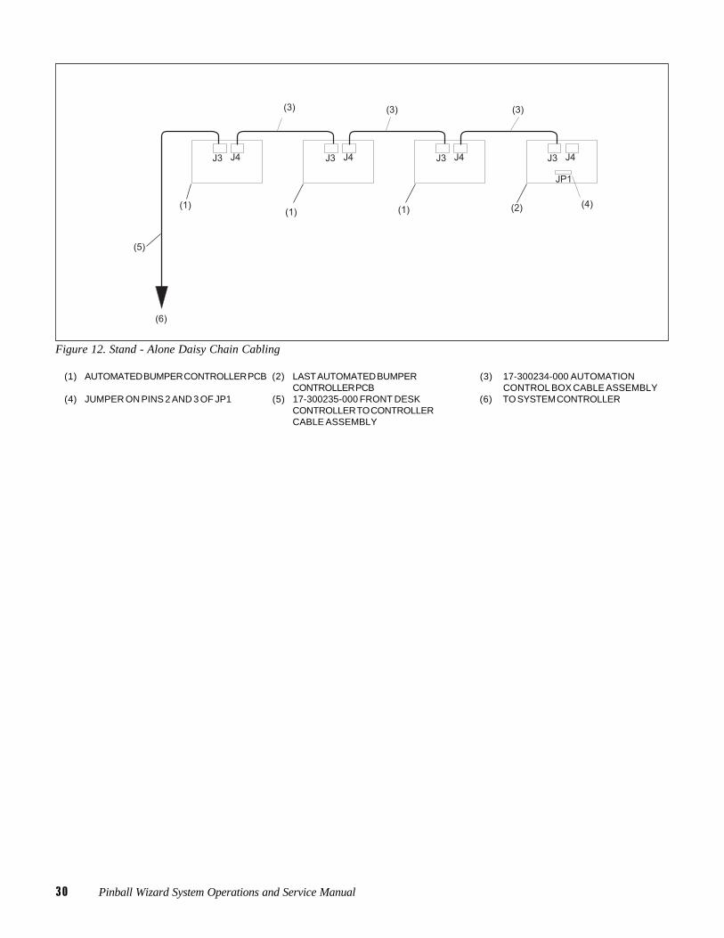
Figure 12. Stand - Alone Daisy Chain Cabling
(1) AUTOMATED BUMPER CONTROLLER PCB (2) LAST AUTOMATED BUMPER (3) 17-300234-000 AUTOMATIONCONTROLLER PCB CONTROL BOX CABLE ASSEMBLY
(4) JUMPER ON PINS 2 AND 3 OF JP1 (5) 17-300235-000 FRONT DESK (6) TO SYSTEM CONTROLLERCONTROLLER TO CONTROLLERCABLE ASSEMBLY
Pinball Wizard System Operations and Service Manual 31
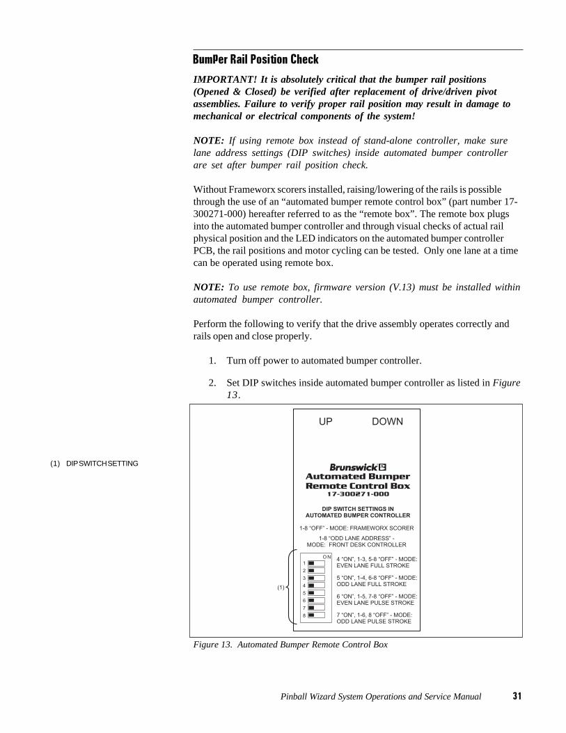
Bumper Rail Position Check
IMPORTANT! It is absolutely critical that the bumper rail positions(Opened & Closed) be verified after replacement of drive/driven pivotassemblies. Failure to verify proper rail position may result in damage tomechanical or electrical components of the system!
NOTE: If using remote box instead of stand-alone controller, make surelane address settings (DIP switches) inside automated bumper controllerare set after bumper rail position check.
Without Frameworx scorers installed, raising/lowering of the rails is possiblethrough the use of an “automated bumper remote control box” (part number 17-300271-000) hereafter referred to as the “remote box”. The remote box plugsinto the automated bumper controller and through visual checks of actual railphysical position and the LED indicators on the automated bumper controllerPCB, the rail positions and motor cycling can be tested. Only one lane at a timecan be operated using remote box.
NOTE: To use remote box, firmware version (V.13) must be installed withinautomated bumper controller.
Perform the following to verify that the drive assembly operates correctly andrails open and close properly.
1. Turn off power to automated bumper controller.
2. Set DIP switches inside automated bumper controller as listed in Figure13.
(1) DIP SWITCH SETTING
Figure 13. Automated Bumper Remote Control Box
32 Pinball Wizard System Operations and Service Manual
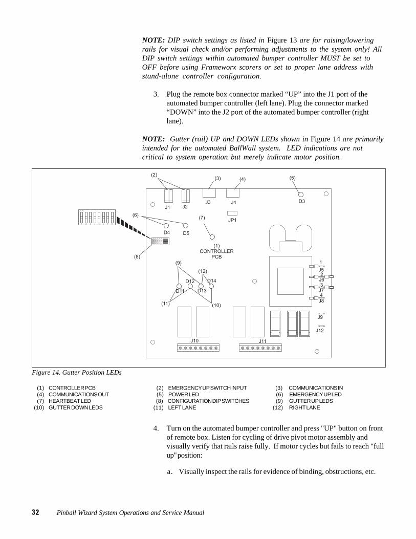
NOTE: DIP switch settings as listed in Figure 13 are for raising/loweringrails for visual check and/or performing adjustments to the system only! AllDIP switch settings within automated bumper controller MUST be set toOFF before using Frameworx scorers or set to proper lane address withstand-alone controller configuration.
3. Plug the remote box connector marked “UP” into the J1 port of theautomated bumper controller (left lane). Plug the connector marked“DOWN” into the J2 port of the automated bumper controller (rightlane).
NOTE: Gutter (rail) UP and DOWN LEDs shown in Figure 14 are primarilyintended for the automated BallWall system. LED indications are notcritical to system operation but merely indicate motor position.
Figure 14. Gutter Position LEDs
(1) CONTROLLER PCB (2) EMERGENCY UP SWITCH INPUT (3) COMMUNICATIONS IN(4) COMMUNICATIONS OUT (5) POWER LED (6) EMERGENCY UP LED(7) HEARTBEAT LED (8) CONFIGURATION DIP SWITCHES (9) GUTTER UP LEDS
(10) GUTTER DOWN LEDS (11) LEFT LANE (12) RIGHT LANE
4. Turn on the automated bumper controller and press "UP" button on frontof remote box. Listen for cycling of drive pivot motor assembly andvisually verify that rails raise fully. If motor cycles but fails to reach "fullup" position:
a. Visually inspect the rails for evidence of binding, obstructions, etc.
Pinball Wizard System Operations and Service Manual 33
b. If no obstructions/binding condition is apparent, contact Brunswick at1-800-323-8141.
5. Press "DOWN" button on front of remote box. Listen for cycling ofdrive pivot motor assembly and visually verify that rails lower fully. Ifmotor cycles but fails to reach "full down" position:
a. Visually inspect the rails for evidence of binding, obstructions, etc.
b. If no obstructions/binding condition is apparent, contact Brunswick at1-800-323-8141.

34 Pinball Wizard System Operations and Service Manual
Service and MaintenanceThe Pinball Wizard system was designed to simplify the required scheduledmaintenance or servicing done by the customer. There are no required lubrica-tion instructions to perform and at the time of print of this manual, center person-nel are responsible for performing the following maintenance inspections.
NOTE: The Troubleshooting section at the rear of this manual containscorrective actions for system faults. The items listed here are NOT recom-mended procedures for troubleshooting the system.
Periodic Inspections
WARNING: The lane(s) being serviced should be placed out of service atthe control desk until servicing/inspections are finished. Failure todeactivate lane(s) may cause injury to personnel!
1. At the control desk with "Lane Status" screen displayed:
a. Press lane number and "HOLD" keys at the same time. Lane isnow out of service.
b. Press lane number and "HOLD" keys at the same time again tomake lane available for use.
2. At recommended intervals of 20,000 cycles or six months of operation,visually inspect the set screws on the drive and driven pivot assemblycrank arms for security. Tighten set screws as needed.
3. Visually inspect the jam nuts on the connecting link turnbuckles forevidence of wear, looseness, or damage; correct turnbuckles as needed.The required length of assembled turnbuckles is 4.31 to 4.38 “.
4. Inspect the bushings on the rail upright and correct any conditions thatmay exist.
5. Visually inspect ALL mechanical linkages (i.e. cross lane links, crankarms, rail couplers) for evidence of excessive wear. Replace worncomponents as needed.
NOTE: If replacement of drive/driven pivot assemblies is required, abumper rail position check MUST be performed afterward. Refer to"Bumper Rail Position Check" paragraph in this manual.
Pinball W
izard System
Operations and S
ervice Manual
35
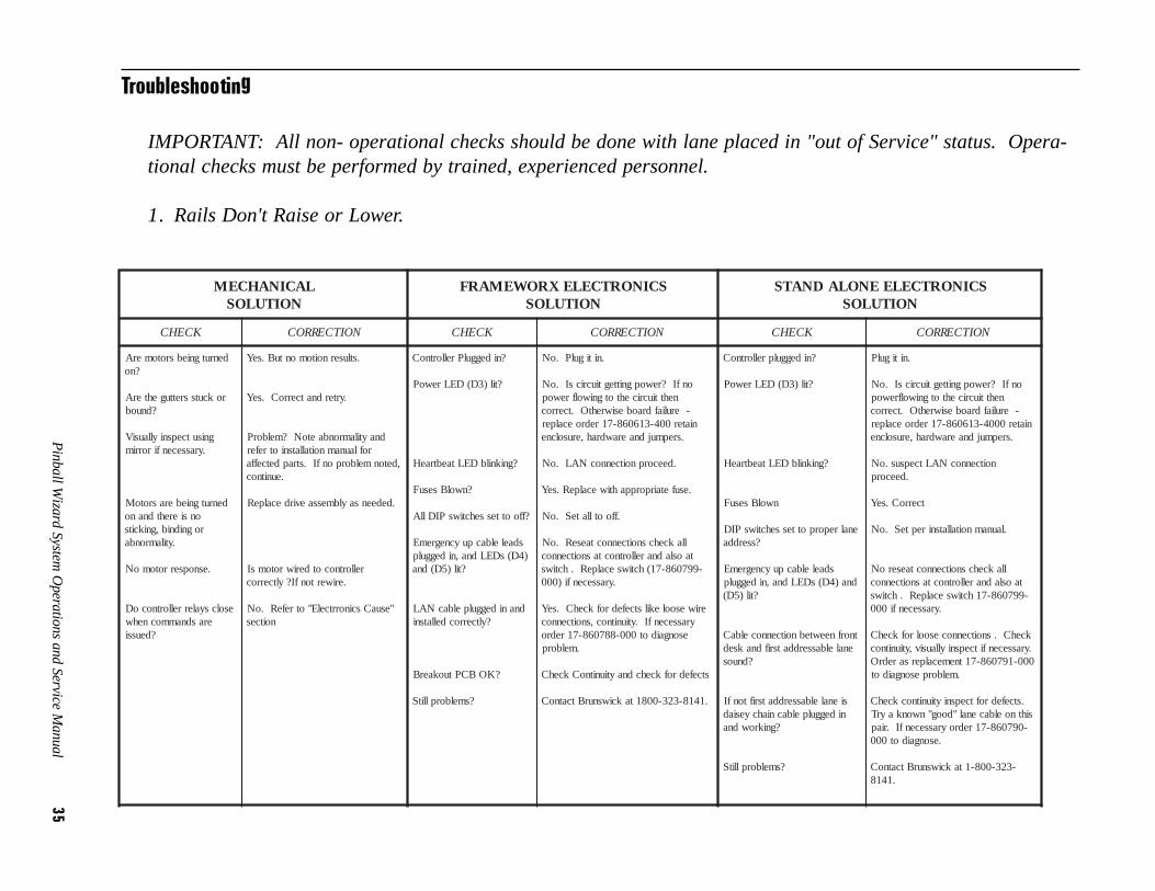
Troubleshooting
IMPORTANT: All non- operational checks should be done with lane placed in "out of Service" status. Opera-tional checks must be performed by trained, experienced personnel.
1. Rails Don't Raise or Lower.
LACINAHCEMNOITULOS
SCINORTCELEXROWEMARFNOITULOS
SCINORTCELEENOLADNATSNOITULOS
KCEHC NOITCERROC KCEHC NOITCERROC KCEHC NOITCERROC
denrutgniebsrotomerA?no
rokcutssrettugehterA?dnuob
gnisutcepsniyllausiV.yrassecenfirorrim
denrutgnieberasrotoMonsierehtdnanorognidnib,gnikcits
.ytilamronba
.esnopserrotomoN
esolcsyalerrellortnocoDerasdnammocnehw
?deussi
.stlusernoitomontuB.seY
.yrterdnatcerroC.seY
dnaytilamronbaetoN?melborProflaunamnoitallatsniotrefer
,detonmelborponfI.strapdetceffa.eunitnoc
.dedeensaylbmessaevirdecalpeR
rellortnocotderiwrotomsI.eriwertonfI?yltcerroc
"esuaCscinorrtcelE"otrefeR.oNnoitces
?nideggulPrellortnoC
?til)3D(DELrewoP
?gniknilbDELtaebtraeH
?nwolBsesuF
?ffoottessehctiwsPIDllA
sdaelelbacpuycnegremE)4D(sDELdna,nideggulp
?til)5D(dna
dnanideggulpelbacNAL?yltcerrocdellatsni
?KOBCPtuokaerB
?smelborpllitS
.nitigulP.oN
onfI?rewopgnittegtiucricsI.oNnehttiucricehtotgniwolfrewop
-eruliafdraobesiwrehtO.tcerrocniater004-316068-71redroecalper
.srepmujdnaerawdrah,erusolcne
.deecorpnoitcennocNAL.oN
.esufetairporppahtiwecalpeR.seY
.ffootllateS.oN
llakcehcsnoitcennoctaeseR.oNtaosladnarellortnoctasnoitcennoc
-997068-71(hctiwsecalpeR.hctiws.yrassecenfi)000
eriwesoolekilstcefedrofkcehC.seYyrassecenfI.ytiunitnoc,snoitcennoc
esongaidot000-887068-71redro.melborp
stcefedrofkcehcdnaytiunitnoCkcehC
.1418-323-0081takciwsnurBtcatnoC
?nideggulprellortnoC
?til)3D(DELrewoP
?gniknilbDELtaebtraeH
nwolBsesuF
enalreporpottessehctiwsPID?sserdda
sdaelelbacpuycnegremEdna)4D(sDELdna,nideggulp
?til)5D(
tnorfneewtebnoitcennocelbaCenalelbasserddatsrifdnaksed
?dnuos
sienalelbasserddatsriftonfInideggulpelbacniahcyesiad
?gnikrowdna
?smelborpllitS
.nitigulP
onfI?rewopgnittegtiucricsI.oNnehttiucricehtotgniwolfrewop
-eruliafdraobesiwrehtO.tcerrocniater0004-316068-71redroecalper
.srepmujdnaerawdrah,erusolcne
noitcennocNALtcepsus.oN.deecorp
tcerroC.seY
.launamnoitallatsnirepteS.oN
llakcehcsnoitcennoctaeseroNtaosladnarellortnoctasnoitcennoc-997068-71hctiwsecalpeR.hctiws
.yrassecenfi000
kcehC.snoitcennocesoolrofkcehC.yrassecenfitcepsniyllausiv,ytiunitnoc000-197068-71tnemecalpersaredrO
.melborpesongaidot
.stcefedroftcepsniytiunitnockcehCsihtnoelbacenal"doog"nwonkayrT
-097068-71redroyrassecenfI.riap.esongaidot000
-323-008-1takciwsnurBtcatnoC.1418
36P
inball Wizard S
ystem O
perations and Service M
anual
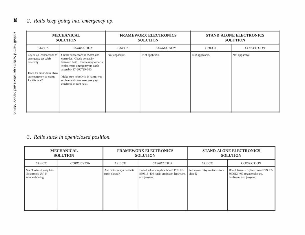
2. Rails keep going into emergency up.
3. Rails stuck in open/closed position.
LACINAHCEMNOITULOS
SCINORTCELEXROWEMARFNOITULOS
SCINORTCELEENOLADNATSNOITULOS
KCEHC NOITCERROC KCEHC NOITCERROC KCEHC NOITCERROC
otsnoitcennocllakcehCelbacpuycnegreme
.ylbmessa
wohsksedtnorfehtseoDsutatspuycnegremena
?enalsihtrof
dnahctiwstasnoitcennockcehCytiunitnockcehC.rellortnoc
aredroyrassecenfI.htobneewtebelbacpuycnegremetnemecalper
.000-997068-71ylbmessa
yawsmrahnisiydobonerusekaMpuycnegremeraelcdnaenalno
.ksedtnorftanoitidnoc
.elbacilppatoN .elbacilppatoN .elbacilppatoN .elbacilppatoN
LACINAHCEMNOITULOS
SCINORTCELEXROWEMARFNOITULOS
SCINORTCELEENOLADNATSNOITULOS
KCEHC NOITCERROC KCEHC NOITCERROC KCEHC NOITCERROC
otnIgnioGsrettuG"eeSni"pUycnegremE
.gnitoohslebuort
stcatnocsyalerrotomerA?desolckcuts
-71N/Pdraobecalper-eruliafdraoB,erawdrah,erusolcneniater004-316068
.srepmujdna
kcutsstcatnocyalerrotomerA?desolc
-71N/Pdraobecalper-eruliafdraoB,erusolcneniater004-316068
.srepmujdna,erawdrah
Pinball W
izard System
Operations and S
ervice Manual
37
LACINAHCEMNOITULOS
SCINORTCELEXROWEMARFNOITULOS
SCINORTCELEENOLADNATSNOITULOS
KCEHC NOITCERROC KCEHC NOITCERROC KCEHC NOITCERROC
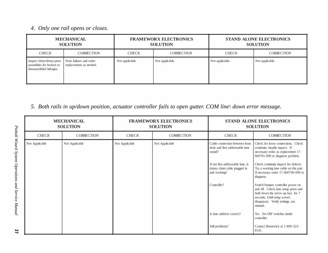
tovipnevird/evirdtcepsnIronekorbrofseilbmessa
.segaknildelbmessassid
redrodnaseruliafetoN.dedeensastnemecalper
.elbacilppatoN .elbacilppatoN .elbacilppatoN .elbacilppatoN
LACINAHCEMNOITULOS
SCINORTCELEXROWEMARFNOITULOS
SCINORTCELEENOLADNATSNOITULOS
KCEHC NOITCERROC KCEHC NOITCERROC KCEHC NOITCERROC
elbacilppAtoN elbacilppAtoN elbacilppAtoN elbacilppAtoN tnorfneewtebnoitcennocelbaCenalelbasserddatsrifdnaksed
?dnuos
si,enalelbasserddatsriftonfInideggulpelbacniahcyesiad
?gnikrowdna
?rellortnoC
?tcerrocsserddaenalsI
?smelborpllitS
kcehC.snoitcennocesoolrofkcehCfI.tcepsniyllausivytiunitnoc
-71tnemecalpersaredroyrassecen.melborpesongaidot000-197068
.stcefedroftcepsniytiunitnockcehC.riapsihtnoelbacenalgnikrowayrTot000-097068-71redroyrassecenfI
.esongaid
norewoprellortnocrepmubhctiwSdnasserpputesenalkcehC.ffodna
7rofyekpuworraehtnwoddlohneercsputeslitnU.sdnoces
ees,sgnittesyfireV.sraeppasid.launam
edisnisehctiwsPIDteS.oN.rellortnoc
-323-008-1takciwsnurBtcatnoC.1418
4. Only one rail opens or closes.
5. Both rails in up/down position, actuator controller fails to open gutter. COM line\ down error message.
38 Pinball Wizard System Operations and Service Manual
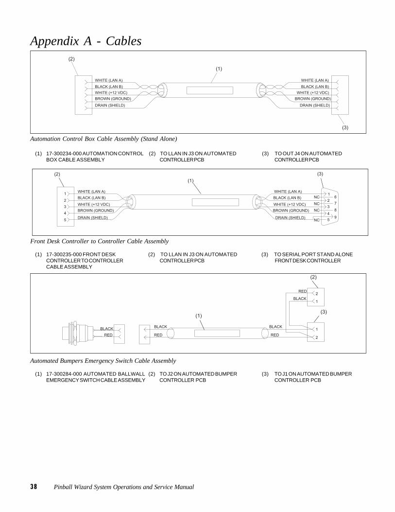
Appendix A - Cables
Automation Control Box Cable Assembly (Stand Alone)
(1) 17-300234-000 AUTOMATION CONTROL (2) TO LLAN IN J3 ON AUTOMATED (3) TO OUT J4 ON AUTOMATEDBOX CABLE ASSEMBLY CONTROLLER PCB CONTROLLER PCB
Front Desk Controller to Controller Cable Assembly
(1) 17-300235-000 FRONT DESK (2) TO LLAN IN J3 ON AUTOMATED (3) TO SERIAL PORT STAND ALONECONTROLLER TO CONTROLLER CONTROLLER PCB FRONT DESK CONTROLLERCABLE ASSEMBLY
Automated Bumpers Emergency Switch Cable Assembly
(1) 17-300284-000 AUTOMATED BALLWALL (2) TO J2 ON AUTOMATED BUMPER (3) TO J1 ON AUTOMATED BUMPEREMERGENCY SWITCH CABLE ASSEMBLY CONTROLLER PCB CONTROLLER PCB
Pinball Wizard System Operations and Service Manual 39
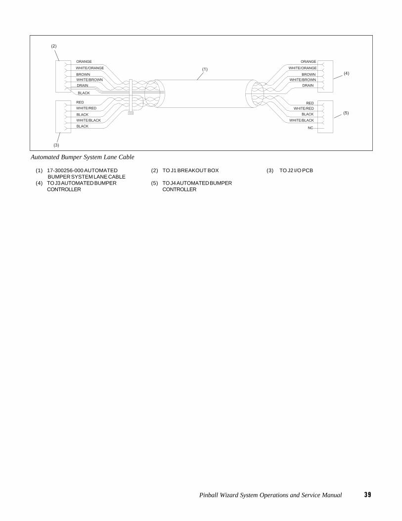
Automated Bumper System Lane Cable
(1) 17-300256-000 AUTOMATED (2) TO J1 BREAKOUT BOX (3) TO J2 I/O PCB BUMPER SYSTEM LANE CABLE
(4) TO J3 AUTOMATED BUMPER (5) TO J4 AUTOMATED BUMPERCONTROLLER CONTROLLER