operations & maintenance plan
TRANSCRIPT
B-1
APPENDIX B
OPERATIONS & MAINTENANCE PLAN
(O & M Plan)
Guidance Manual for
Preparing Public Water Supply System
O & M Plans
MAY, 2000 Revision.05172000.OES.2.0
Drinking Water Permitting & Engineering Program Georgia Environmental Protection Division
205 Butler Street, S.E. Floyd Towers East, Suite # 1362
Atlanta, Georgia 30334
B-2
FOREWORD The guidance and procedures outlined in this document are intended to supplement existing requirements. They do not replace the rules and regulations administered by the Georgia EPD. Nothing in this document intended to be more stringent than the regulatory requirements. The guidance and procedures herein are not an adjudication or a regulation. The guidance and procedures merely explain how and on what basis Drinking Water Permitting and Engineering Program of the EPD will administer and implement its responsibilities with respect to Operations and Maintenance Plans. EPD reserves the discretion to deviate from the guidance and procedures in this document if circumstances warrant. In the preparation of this part of the publication, EPD primarily used the technical guidance documents published by the Bureau of Water Supply Management of the State of Pennsylvania's Department of Environmental Protection. The following two technical guidance documents are used: 1. Pennsylvania Department of Environmental Protection, Bureau of Water Supply Management,
"Public Water Supply Manual, Part V-Section I and II - Operations and Maintenance (ID No. 383-3110-111)", November 1, 1997.
2. Pennsylvania Department of Environmental Protection, Bureau of Water Supply Management,
"Public Water Supply Manual, Part V (Appendix A) Operations and Maintenance for Small Groundwater Systems (ID No. 383-3110-211)", May 1, 1999.
B-3
OPERATION & MAINTENANCE PLAN OUTLINE
FOREWORD…………………………………………………………………………………………B-2
INTRODUCTION……………………………………………………………………………………B-5
SECTION I - PREPARATION OF OPERATION & MAINTENANCE PLAN ………….…B-6
CHAPTER 1 - DESCRIPTION OF FACILITIES …………………………………………………. B-13 CHAPTER 2 - START-UP AND NORMAL OPERATING PROCEDURES ……………………..B-18 CHAPTER 3 - PLANNED MAINTENANCE PROGRAM …………………………………………B-24 CHAPTER 4 - RECORDS AND REPORTING SYSTEM ………………………………………….B-28 CHAPTER 5 - SAMPLING AND ANALYSIS PROGRAM AND COMPLIANCE MONITORING ……………………………………………………B-34
CHAPTER 6 - PUBLIC NOTIFICATION …………………………………………………….B-49 CHAPTER 7 - STAFFING AND TRAINING………………………………………………………..B-53.
CHAPTER 8 - SANITARY SURVEY PROGRAM …………………………………………………B-57 CHAPTER 9 - SAFETY PROGRAM …………………………………………………………………B-60
CHAPTER 10 - EMERGENCY PLAN AND OPERATING PROCEDURES ……………………..B-70
SECTION II - OPERATION AND MAINTENANCE PROCEDURES ……………………..B-73
CHAPTER 1 - SOURCES OF SUPPLY ………………………………………………………………B-
73
CHAPTER 2 - TREATMENT ……………………………….………………………………....B-79
CHAPTER 3 - DISTRIBUTION ……………………………………………………………………...B-
130
CHAPTER 4 - LABORATORY EQUIPMENT MAINTENANCE ………………………………...B-145
B-4
SECTION III - OPERATION AND MAINTENANCE FOR SMALL GROUNDWATER SYSTEMS …………………………………B-155 INTRODUCTION ………………………………………………………………………………….B-155 PART A - GUIDANCE ……………………………………………………………………………………B-156
A.1 - DESCRIPTION OF FACILITIES ……………………………………………………………..B-156 A. 2 - START-UP AND NORMAL OPERATING PROCEDURES ………………………………B-157 A.3 - MAINTENANCE ……………………………………………………………………………….B-160 A. 4 - RECORDS ………………………………………………………………………………….…..B-161 A. 5 - SAMPLING AND AND COMPLIANCE MONITORING …………………………….……B-163
A. 6 - PUBLIC NOTIFICATION …………………………………………………….……….B-169 A. 7 - STAFFING AND TRAINING ……………………………………………………………….…B-171
A. 8 - SANITARY SURVEY PROGRAM ……………………………………………………………B-171 A. 9 - SAFETY PROGRAM …………………………………………………………………………..B-172
A. 10 - EMERGENCY RESPONSE PLAN …………………………………………………………..B-174
TECHNICAL INFORMATION ……………………………………………………………..B-175
A.11 - SOURCES OF SUPPLY ………………………………………………………………………..B-
175
A.12 - TREATMENT ………………………………………………………………………….B-176
A.13 – DISTRIBUTION ………………………………………………………………………………..B-
180 A.14 - LABORATORY EQUIPMENT MAINTENANCE …………………………………………..B-192
B-5
INTRODUCTION The purpose of this part is to provide assistance to the water supplier in the preparation and development of an Operation and Maintenance (O & M) Plan and the operation and maintenance procedures for each system. It is presented in three sections: Section I contains the detailed guidance on how to prepare an O & M Plan for the system. Once an acceptable plan is in place, it becomes a reference book for the entire water system. Section II contains detailed operation and maintenance procedures that can be used to assist the water supplier in preparing the O & M Plan. These detailed O & M procedures are provided as examples for describing typical facilities, and operations and maintenance procedures. This information can be used or adapted for use on any water system. However, the water supplier may want to develop customized procedures applicable to a particular process or system. Section III is to assist the small ground-water systems in the preparation and development of an Operation and Maintenance (O & M) Plan.
B-6
SECTION I - PREPARATION OF AN O & M PLAN
Why is an O & M Plan necessary? This plan should be developed by every public water supplier to provide a written source of material that can be easily referred to for guidance in operating a water system. This plan will be a valuable reference tool for the operating personnel because standard operating procedures for the system and guidelines for start-up and emergency situations will beat their fingertips. The O &M Plan will also provide a ready reference for all equipment data which is necessary for performing normal maintenance and for ordering replacement parts and supplies. It will be an organized system for keeping records of the operation of the system. These records are useful for monthly and annual reports, as supporting documentation of proper operation, and to support the need for replacement or upgrading of treatment facilities. It will have detailed instructions for water sampling and testing which are required for compliance with the Safe Drinking Water Act (SDWA) and for routine monitoring of the treatment process for compliance with generally accepted good waterworks procedures. The plan will contain information regarding start-up and normal operating procedures and emergency operating procedures; descriptions of equipment and facilities; organization responsibilities; names, addresses, and phone numbers of all key personnel; all contractors and suppliers; and state and local officials. The O & M Plan will become a training manual to provide personnel with a handy source reference while they learn to operate the facilities. The O & M Plan will be used by experienced operating personnel to monitor normal procedures for changes or emergency conditions; as a source for names and phone numbers when emergency notification is required; and as a check of proper maintenance procedures. How to Develop an Effective O& M Plan O & M Plans are often prepared by engineers and managers; however, they must be certain that they obtain information from persons actually experienced in plant operation and maintenance. The procedures must be described in terms and language which are readily accepted and understood by the operators. Because of the technical nature of the water treatment process, a basic level of knowledge and understanding by the operators must be assumed. The experienced operator will usually refer to the O & M Plan for confirmation of normal operation and maintenance procedures and as a reference guide for unusual operating conditions. The entry level operator should frequently refer to the O & M Plan for guidance and instruction, Some water suppliers may have O & M Plans or certain parts of O & M Plans established for their system. These may include Emergency Response Plans, Safety Programs, Water Conservation Programs, Cross-Connection Control Programs, or other formalized procedures. This guidance manual
B-7
is not intended as a required format which must be followed, but as a presentation of procedures which can be considered for your use in the preparation of your O& M Plan. Plans and programs which have been accepted as good, operating procedures can be directly included in your O & M Plan without rewriting; however, it would be a good idea to review and update your procedures. Your O & M Plan will be a collection of plans and programs which will probably be stored in loose-leaf notebooks. The appearance of your plan is not as important as the availability of the information to the operating personnel and the ability to revise and update it. How to Use Section I: Preparation of an 0peration and Maintenance Plan The chapters in Section I are organized in a simple and logical manner that can be followed in the preparation of an O & M Plan for a water supply system. Each chapter in Section I provides details of information which should be considered in the preparation of an O & M Plan. The following is a brief look at what is in each chapter of Section I to help locate specific subjects and areas:
Chapter 1 - Description of Facilities • The Owner(s) - Who is responsible and where can they be contacted? • The Service Area - How far does the system extend? • Permits - What kind of permits and what are the conditions? • System/Facilities Description - Describes sources, treatment, pumping, transmission and distribution
system, storage facilities, and other features of the system. • Distribution Map - What should a distribution map show?
• Flow Charts for Treatment Plants - How to show the treatment process in simple terms.
• Pressure Gradients - Pressure surveys and hydraulic gradients.
• Other Maintenance Requirements - What is needed? What areas need help or equipment? This
section suggests guidelines for major maintenance consideration.
Chapter 2 - Start-Up and Normal Operating Procedures • Process Description - This helps to understand the operating procedures.
• Relationship to Adjacent Processes - How does each process work with the next process?
• Controls - What controls each unit and what can be controlled?
B-8
• Start-up Procedures - How to start up? What kinds of check procedures are needed? What is the sequence of start-up?
• Normal Operating Procedures - What are normal operating procedures? What are the check points
for normal operation? What are the minimum and maximum values of the checkpoints? What is the normal range of chemical dosages?
• Alternate Operating Procedures - How does the plant operate when the normal conditions change, the raw water quality changes, or a process or piece of equipment is out of service? An alternate operation procedure is usually a planned change to accommodate major maintenance, increased demand, or use of an alternate source.
• Emergency Operating Procedures - An emergency is thought to be sudden, unforeseen, or
unexpected, requiring immediate action. A water supplier should anticipate that these conditions could happen and by having procedures established for those conditions, many emergencies become just alternate operating procedures. The water supplier is then able to continue safe, adequate service until the return to normal conditions.
• Common Operating Problems - What kinds of problems regularly occur? What causes them? How
can they be controlled or prevented?
Chapter 3 - Planned Maintenance Program • Equipment Data Base Equipment Record Cards - Used to record and document the maintenance
history for each piece of equipment. • Maintenance Procedures, Routine and Periodic.
• Work Order System - The work order format and file system.
• Prioritizing Work Requests - Planning and scheduling maintenance.
• Spare Parts Inventory Control.
• In-house vs. Contracted Labor.
• Manufacturer's Recommendations.
Chapter 4 - Records and Reporting System
• Types of Records. Physical Plant Operation
Regulatory Agencies Preventative Maintenance Operating Costs Personnel
B-9
Emergency Conditions
• Preservation of Records.
Chapter 5 - Sampling and Analysis Program and Compliance Monitoring • Sampling and Analysis - How to schedule the sampling. What are the criteria for sampling
locations? Who collects samples and how do they handle them? • Quality Assurance of Samples - How to take the samples. What precautions are taken to prevent
contamination of the sample? What are the time requirements for each type of sample? • Compliance Monitoring - Who checks if it is on schedule? Who interprets results? How are records
kept?
Chapter 6 - Public Notification • Regulatory Requirements for Public Notification - Safe Drinking Water Act
• Content of Notification - Information to be included and description of notice.
• Advance Preparations - Media notification and direct notice.
• Sample Notices.
Chapter 7 - Staffing and Training • Staffing - Influences and task classifications.
• Job Descriptions - How are job descriptions prepared?
• Organizational Staff - Defines the responsibilities of each position.
• Certification - Under Georgia law.
• Training Requirements - Needs and availability.
Chapter 8 - Sanitary Survey Program • Watershed Surveillance - Geology, sources of pollution, flooding.
B-10
• Evaluation of Source Protection, Intake Structures, and Transmission Facilities - Facilities to evaluate, evaluation of hazards, evaluation of operating ability, condition of facilities, vulnerability of transmission mains.
• Treatment Facilities Inspection - Raw and finished water quality review, condition and operating
capabilities of components and evaluation of power systems. • Finished Water Storage Facilities - Capacities, sanitary protection, condition, and water quality. • Distribution System and Pressure Surveys - Water quality, unaccounted-for water, valve and fire
hydrant program, and tabulation of pressure survey results.
Chapter 9 - Safety Program • How to start and maintain a program - Designate responsible person, form committees, and issue
policy. • O & M Safety Plan - Identify hazards, develop safety manual.
Chapter 10 - Emergency Plan and Operating Procedures • Emergency Plan and Operating Procedures Preparation - Components, emergencies to be addressed,
and emergency equipment hookup procedures. • Evaluation Program - Reviews and inspections, rehearsals/drills.
• Emergency Operating Procedures. • Emergency Plan and Operating Procedures Outline - (sample).
How to Use Section II: Operations and Maintenance Procedures The chapters in Section II are presented to provide easy to follow examples of typical operations and maintenance procedures for a water system. This information should be readily adaptable for use in the O & M Plans of a large number of water suppliers. Some systems will not have all of the processes described and some will have other, more sophisticated processes. The water supplier may adapt those parts of this information they want and can use other sources for similar material. The following is a brief overview of what is in each chapter.
Chapter 1 - Sources of Supply • Surface Water - Quality, quantity, permits, treatment, watershed. • Intakes - Intake appurtenances, intakes on rivers and streams, silt removal operations and typical
maintenance.
B-11
• Dams - Types and sizes, regulation, emergency preparedness, O & M procedures.
• Wells - Records, pumps, well bore maintenance, water quality.
Chapter 2 - Treatment • Chemical Addition and Handling - Coagulation and pH adjustment, taste and odor, corrosion,
disinfection, fluoridation, and softening chemicals. • Conventional Filtration Treatment Plant - Rapid mix, coagulation/flocculation, sedimentation, solids
contact units, filtration. • Disinfection - Chlorination, chlorine dioxide, other disinfection systems. • Fluoridation - Sodium fluoride, hydrofluosilicic acid, sodium silicofluoride, start-up, normal
operations, chemical feed equipment, fluoride feed rates and records. • Softening - Lime-soda ash, ion exchange. • Aeration - Start-up, shut-down, normal operations, monitoring, records, maintenance, operation
problems. • Adsorption - Powdered activated carbon, granular activated carbon.
Chapter 3 - Distribution • Plans and Records - Distribution system maps, pressure zones, updating and correcting plans,
production and pumping records. • Distribution System - Transmission and distribution mains, valves, fire hydrants, blow-offs, records. • Pumps - Types of pumps, capacities and purposes, reports of operations and maintenance,
monitoring operations. • Distribution Storage Facilities - Types of reservoirs and tanks, maintenance, safety protection,
records. • Unaccounted-for Water - Basic calculation, normal operating ranges, control. • Maintenance of Water Mains and Services - Customer complaints, water main repairs, thawing of
frozen mains and services.
B-12
Chapter 4 - Laboratory Equipment Maintenance • Glassware, laboratory support equipment, analytical balance. • Jar Test Apparatus - Stirring machine, floc illuminator, beakers • pH Meter - Maintenance, calibration. • Specific Ion Meter - Maintenance, calibration. • Turbidimeter - Maintenance, calibration. • Spectrophotometer - Maintenance, calibration. • Safety Equipment.
Section III - Operation and Maintenance for Small Groundwater Systems This section is a summary of the chapters in Sections I and II which provides assistance for the water systems with a well, disinfection, distribution, and distribution storage. This will be useful to the small groundwater system which does not have engineering or management services available.
B-13
SECTION I - PREPARATION OF AN OPERATION & MAINTENANCE PLAN
CHAPTER 1 - DESCRIPTION OF FACILITIES Chapter I presents key information needed to prepare a physical, operational, and legal description of a public water supply system. 1.0 Owner
A. A description of the owner should provide the following information: operator (if not the owner), contact person(s), addresses, phone numbers, type of ownership, (e.g., private, municipality, authority).
B. An organization chart indicating the chain of command should be included in this chapter.
1.1 Service Area The service area needs to be defined both legally and physically. It may be defined legally for an investor-owned system; by municipal boundary for a municipal water system; or by an authority's articles of incorporation for a regional water authority. A map of the service area, scaled for a single page view or as a fold-out, as well as a view of the distribution network will be an adequate physical description of a small system. See Section 1.4 of this chapter for additional information for a distribution system map. 1.2 Permits Water suppliers must be aware of the permits (including any standard and/or special conditions), laws, and regulations under which their system was built and operates. The O & M Plan for the facility allows the water supplier to integrate these documents into the recordkeeping system for easy retrieval. Copies of various documents may be included in a dedicated appendix or bound under separate cover and appropriately referenced. The section of the manual referencing the permits should have a listing of all permits issued, the facilities approved, dates the permits were issued, and the approved hydraulic capacities. It is important to note that any addition or modification to an existing public water supply will require the approval of EPD. Primary permits include: A. Permit to Operate a Public Water Supply System
B-14
B. Permit to Withdraw Surface Water C. Permit to Withdraw Groundwater D. National Pollution Discharge Elimination System Permit (for establishment of effluent limitations
regarding discharges of wastewater from drinking water treatment plants)
1.3 System/Facilities Description Provide general descriptions of:
A. Sources of Supply 1. Surface source
a. A map of the watershed area indicating the drainage area in square miles, the
location of the water system facilities, and the names of major water sources. b. Indicate the portions of the drainage area owned or controlled by the water system.
c. Indicate the allocated maximum / average daily withdrawal.
2. Wells
a. Describe its location, diameter, depth, length of casing, depth of grout, static water level, pumping water level, pumping rate, date of installation, and any expansions or modifications.
b. Describe drainage area around well site, nearest source of pollution, well seal, and
well enclosure.
c. Include well log, if available, and well driller's name.
d. Describe land ownership access and control.
3. Springs
a. Describe location, capacity, enclosure, land ownership, access, and control.
b. Include date acquired and dates of any modifications.
4. Purchased Water
a. List name of system, address, phone number, and contact person.
b. Date system connection was installed.
c. Describe mode of operation, such as emergency, intermittent, or continuous.
d. Describe pressure and volume (flow) normally received.
e. Describe any additional treatment or pumping required.
f. Describe meter (who owns and is responsible for maintenance) and valving.
B-15
B. Treatment Process
1. General
Describe in general terms the treatment processes used at each facility. Include a flow diagram of the treatment facilities as part of this description.
2. Discuss each part of the treatment process separately with details of the component and
its operation. a. Intake or Raw Water Source
1) Describe the control gates or valves including size and type of operation.
2) Describe any bar screens or trash removal facilities.
3) Describe any raw water pumps.
4) Include dates facilities were installed and/or modified.
b. Chemical Additions
1) It is probably best to describe each chemical addition as a separate process. Provide the name of the chemical applied, chemical formula and strength, name of chemical supplier, and type and size of containers. Indicate the type of chemical feeder, manufacturer's name, model number, maximum capacity, and normal range of feed rates. Describe where the chemical is applied to the water, what controls the dosage of chemical, and what tests are made to determine dosage.
2) What are the safety precautions applicable to this chemical? What safety
equipment is available?
3) When were chemical feeders installed?
c. Rapid Mix
1) What is the size, capacity, number of units, and construction of rapid mix chambers? What is the detention time at design flow rate?
2) Describe the mechanical mixers, manufacturer, size, model, and speed.
3) When were the mixers installed?
d. Flocculation
1) What is the size, capacity, number of units, and construction of the
flocculator chambers? What is the detention time at design flow rate?
B-16
2) Describe the mechanical flocculators, including manufacturer, size, model, and speed.
3) When were the flocculators installed?
e. Sedimentation
1) What is the size, capacity, number of units, detention time at design rate, and construction of the sedimentation basins? Are the basins baffled?
2) Describe the mechanical sludge handling equipment. Are the basins
drained and cleaned periodically?
3) When were the basins installed?
f. Filters
1) Describe their size, capacity, number of units, type and size of filter valves.
2) Filter media. 3) Filter appurtenances, date installed or rebuilt.
g. Clearwell
1) Size, detention time at rated plant capacity.
2) Is the clearwell baffled? h. Disinfection
1) Describe the chlorine chemical, chlorine feed equipment, point of application, and maximum capacity of chlorinators.
C. Major Pumping Systems - Describe the purpose of each pump, size, capacity, rpm, manufacturer,
model number, motor manufacturer, horsepower, motor frame size, location, suction and discharge piping size, and pressure controls. A copy of the pump performance curve showing the impeller diameter, the designed capacity, and head should be included with each pump description.
D. Transmission and Distribution Systems - Total system size (miles of pipe), number of service
connections (or customers), and highlights of transmission line characteristics (main size, dates of original installation and expansions).
E. Storage - Effective capacity, maximum withdrawal rate, materials of construction, coatings, and
altitude valves (i.e., how does the tank operate), and geographic location of reservoirs and elevated storage tanks.
F. Other - Alternative or emergency sources of water, shared utilities (e.g., power generating capabilities employed by others), and other unusual aspects of the system.
B-17
1.4 Distribution Map If not already detailed in the definition of Service Areas, the supplier should have a detailed map of the system's transmission and distribution facilities. On a typical water distribution system map, each type of pipe can be identified with a number. This number may reference the plan number (since most systems require multiple plans). Additionally, valves and hydrants are identified and assigned identification numbers. Pipe sizes, year installed, and materials are identified alongside the pipe. Other pertinent information may be included to aid in the maintenance of the system. While it is not necessary to show all of this information, it is a valuable planning tool for development or rehabilitation. 1.5 Flow Charts for Treatment Plants Each treatment plant should be represented by a line diagram depicting flow of water through the facility. Major equipment and systems should be labeled on the chart. Although proper scale is not required, some attempt should be made to depict the plant in its actual layout 1.6 Pressure Gradients A tabulation of the annual pressure surveys and hydraulic gradients for major transmission mains should be included. 1.7 Other Maintenance Requirements Suppliers need to be aware of and document long-term maintenance needs such as five-year equipment inspections, tank painting, facility (such as roof) requirements, and routine items such as sludge disposal.
B-18
CHAPTER 2 - START-UP AND NORMAL OPERATING PROCEDURES This portion of the O & M Plan discusses the normal operation of each treatment unit/process and provides guidance for alternate and emergency operations. The information provided in this section should address valve positions, capacities of each process, pump adjustments, and process control variables. Schematics and drawings should be used as part of these discussions. 2.0 Process Description
A well-written and prepared O & M Plan provides a means to understand the overall objectives of the treatment plant in addition to the immediate objectives of each process. In order to do this, the O & M Plan must provide detailed descriptions of the various treatment processes in the plant.
A. The descriptions of the individual processes should follow the same order as the flow
through the plant. It should contain information regarding the expected results or efficiency of each process and the anticipated operating parameters for each process. For example:
1. Aeration - used as a method for oxidation of iron and manganese and for the
removal of hydrogen sulfide, carbon dioxide and volatile organic compounds through oxidation and stripping;
2. Rapid Mix - provides quick and thorough contact with chemical treatment aids
prior to coagulation/flocculation; 3. Coagulation/flocculation - causes suspended and dissolved particles to "clump"
together under the influence of chemical aids for easy removal; 4. Sedimentation - removes suspended or dissolved matter (turbidity) from water; 5. Filtration - removes suspended or colloidal particles from water as it is passed
through the filter media; 6. Disinfection - destroys or inactivates harmful, disease-causing microorganisms; 7. Chemical Addition/Handling - utilizes various chemicals/equipment to enhance
the treatment or quality of water; 8. Fluoridation - provides for the reduction of tooth decay in the general
population. The addition of fluoride compounds to water is based upon local and state requirements;
9. Softening - removes dissolved magnesium and calcium compounds present as
carbonate or noncarbonate forms. B. Provide a brief description of each unit within each process.
B-19
1. Identify the number of units available and state their operating or standby status.
2. Provide a physical description of each unit including:
a. Dimensions - length, width, depth, diameter;
b. Design loadings/capacities - gpm, lbs/ft2, gaIs/ft2, etc. 3. A description should be provided for each major component of a unit.
a. The description should reference the component's relationship to other components within the unit and should include:
1) Functions;
2) Limitations; 3) Operating features; 4) Component interlocks.
2.1 Relationship to Adjacent Processes
The operation of a process is made clearer by understanding the processes that both precede and follow it.
A. Provide a general description giving type and function of preceding units and processes
as they relate to the unit and process under consideration. This description should include the effects of inefficient operation of the preceding processes upon the process under consideration.
B. Provide a general description, giving type and function of supporting processes as they
relate to the process under consideration. C. Provide a general description, giving type and function of following processes as they
relate to the process under consideration. This description should include the effects of inefficient operation of the process.
2.2 Controls The key to the proper operation of a process is understanding how to control the equipment variables as well as the process variables. A. Describe methods of controlling each component of the process including any limitations to
process operation.
Example:
1. Flow rates; 2. Chemical Dosages (List each chemical and normal dosage in lbs/day or mg/L);
B-20
3. Other.
2.3 Start-Up Successful start-up of new or out-of-service facilities is dependent upon having a well-defined procedure to follow which details all steps involved. For example: A. Equipment Inspection
1. Physical: The O & M Plan should include a procedure for performance of a physical inspection of all units.
a. All tanks should be checked for construction debris such as boards, concrete chunks,
loose nuts and bolts, tools, etc. b. All weirs, baffles, sumps, etc. should be checked for missing bolts, caulking, proper fit,
defective protective coatings or other discrepancies which may affect the immediate or future operation of the unit or process.
2. Mechanical: The mechanical inspection prior to start-up is extremely important for a smooth
start-up and ensured operation. a. The facilities manager should prepare a list of all gates and valves and indicate their
proper position (i.e., open or closed). The inspection should verify the position and ensure the proper operation and seating of valves and gates. The position of gate stops should be checked at this time.
b. Piping should be checked to ensure that all test plates have been removed and that any
pressure reliefs are properly sized and in place. c. A listing of all motors should be prepared to guide a visual inspection for: 1) Damage; 2) Proper wiring; 3) Obstructions which would interfere with operation; 4) Proper mounting.
3. Electrical: The electrical inspection of all systems prior to start-up is extremely critical. A large percentage of future problems can be eliminated by careful attention to detail at this stage of start-up.
a. All Motor Control Centers (MCC) must be checked for: 1) Loose or disconnected wiring; 2) Proper sizing of fuses and breakers; 3) Properly-connected wiring.
B-21
b. All controls/instrumentation must be checked for:
1) Adjustment; 2) Calibration; 3) Operation; 4) Electrical interlocks - must be checked so the operation or non-operation of
interlocked units is assured. B. Initial Preventive Maintenance
Prior to the operation of any motors or other mechanisms, a list must be prepared which details and verifies the lubrication, oil, and initial adjustments as recommended by the manufacturer's manual.
C. Operational Checks
After the preventive maintenance procedure is completed, an operational check must be performed for:
1. Proper motor rotation; 2. Operating mechanisms clearances (i.e., rubbing safety guards); 3. Chain and belt adjustments; 4. Scraper/skimmer operations for catching or binding.
D. Safety Checks After the operational checks, the safety features must be verified to ensure that:
1 . All safety guards are securely in place; 2. All safety placards/warning labels are in place; 3. All specialized safety equipment is available and operable; 4. Operating personnel are familiar with safety equipment and procedures; 5. All chlorine monitors, where used, are operational; 6. Chlorine exhaust ventilation is operational; 7. Chemicals are properly identified and properly used.
E. Equipment Adjustments
1. Identify and verify all initial adjustments prior to operation of equipment. 2. Provide for follow-up of adjustments after initial operation.
F. Start-up Procedures
1. Identify and verify sequential start-up procedures for each unit (for reference, see Section ll, Chapter2 - Treatment). Reference the operation of preceding units/processes.
2. Sequential procedures must be listed in a Standard Operating Procedure (SOP). 3. Influent water quality for each unit/process must be verified to ensure design loading is not
exceeded. Water quality testing should include standards and procedures as noted in Chapter
B-22
5 of this section. Water quality requirements for a particular process should be noted in the SOP for the preceding process.
4. The Standard Operating Procedure should also indicate the start-up status of the process. For
example: a. The clearwell should be full of water at start-up. This water should meet the minimum
water quality standards (i.e., turbidity, iron and manganese levels, chlorine residual, etc.).
b. Filters should be backwashed prior to being placed in operation (see Section II, Chapter
2 - Treatment for explanation and description of backwash procedures). 2.4 Operating Procedures
A. Normal Operating Procedures
These will provide a description of the normal operation of each process. Each description assumes that the process is operating properly as designed and that all influent/effluent parameters meet the required standards. The following items should be included:
1. A general description of the process including schematics and related diagrams (see
Chapter 1, Section 1.3 of this section). 2. A description of the influent water quality including any anticipated variations should be
provided for each unit/process. The description should include average, maximum, and minimum conditions. Reference should be made for any sampling/testing procedures which are involved (see Chapter 5 of this section).
3. A description of all variables which may have an effect upon the unit/process operation.
The maximum and minimum conditions should be indicated. a. A description of process variables would include loadings and feed rates
applicable to the unit/process. b. A description of equipment variables would include speed settings, pump
settings, etc. for the unit/process under consideration. Individual components must be considered in this description.
4. A description of valve positions related to normal operation (i.e., normally closed,
normally open) of the process under operation. 5. A general description of the normal dosages of chemicals used in the process under
consideration. The procedure should reference standard procedures for performance of tests (i.e., jar testing) to determine precise dosages (see Section II, Chapter 2 - Treatment, for description of jar tests). Also describe the calibration and adjustment of test equipment to ensure accuracy (see Section II, Chapter 4 - Laboratory Equipment Maintenance).

B-23
B. Alternate Operating Procedures
A description of major operating alternatives for each process should include an explanation of the purpose of each alternative and its effect, if any, on preceding or subsequent processes. This should include schematics and drawings, flow patterns, equipment operations, valving, and standby equipment.
C. Emergency Operating Procedures
A list of potential emergency situations such as power, well and water storage failure, equipment failure, loss of supply, toxic contamination, drought, loss of aeration, chemical or disinfection systems should be prepared (see Chapter 10 - Emergency Plan and Operating Procedures of this section).
1. A description of alternate power and power sources detailing the access to and operation
of the source. 2. A description of the process with schematics and diagrams should indicate warning,
interlock systems, and standby equipment. 3. A description of procedures for process bypass or shut down and the effects should be
accompanied by schematics and diagrams. 4. An emergency notification list identifying who should be contacted by priority should
include names, addresses, normal and alternate phone numbers, the reason for the notification and the type of information required (see Chapter 7, Section 7.2, and Chapter 10 of this section).
2.5 Common Operating Problems A troubleshooting guide, both for mechanical and process, should be available to quickly identify common problems, probable causes, and a brief description of possible control or prevention techniques. Appropriate troubleshooting tables, for easy reference, should be provided in this section. CHAPTER 3 - PLANNED MAINTENANCE PROGRAM The objective of a planned maintenance program is to prevent unplanned, reactive maintenance. To accomplish this, the water supplier's staff must have a working knowledge of the equipment, its required maintenance, and the spare parts to be stocked.
B-24
There must be an effective system to inform the staff of the priorities and frequency of the maintenance which needs to be done. A record of the repairs made to each piece of equipment should be kept. This allows the manager to make appropriate judgements about the maintenance program, the quality and condition of equipment, and when replacement should be planned. 3.0 Equipment Data Base This file, either computerized or manual, inventories each piece of equipment by assigning a unique number, describing its location in the system, and itemizing the details on its nameplate. A. Equipment List - Individual pieces of equipment are numbered according to the facility they are
associated with and their position in the process flow. The number becomes the equipment's identifier whenever maintenance is involved.
There are many numbering systems which can be used, from the very simple for small systems to very complex computerized systems for large systems. The purpose is to develop a system which is useful to the staff in identifying each piece of equipment for maintenance purposes.
B. Equipment Record Cards - Each piece of equipment is registered on a record card containing every
feature about the unit. Where possible, this information is to be taken from the manufacturer's nameplate attached to the unit. Manufacturer's name, address, phone number, contact person, purchase order number, and/or contract number should be included. Additionally, equipment related to the unit, such as the drive motor and gear reducer, is added to the card.
Any O & M documentation, such as as-built drawings, manufacturer's manuals, etc., should be itemized and their file location noted. The equipment record card, normally a two-sided form, is used for noting the maintenance history of the unit.
3.1 Maintenance Procedures All preventive maintenance procedures should be described in detail on a Maintenance Procedure Sheet for each type of unit. Where appropriate, complete details on the types and amounts of lubricants, hoses, packing, and other replacement items should be provided. A. Routine Procedures - All routine procedures should be grouped together on a checklist according to
their scheduled frequency. The procedures normally are scheduled for specific time periods so there is a uniform work load over the calendar year. All work should be done by persons who are qualified and knowledgeable in the operation and maintenance of the equipment.
B. All maintenance procedures should conform to the manufacturer's recommendations to avoid
cancellation of any warranties. Unusual use or environmental factors should be considered when establishing procedures (e.g., wet or dusty conditions would require more frequent maintenance).
3.2 Work Order System All maintenance work should be documented. A work order system is one way to establish a permanent record of maintenance performed. A. Work Order Format - The work order form should have the capability of:
B-25
1. Communicating a work request to the maintenance staff; 2. Authorizing repairs; 3. Planning repairs; 4. Receiving feedback in writing from the maintenance staff; 5. Documenting repair and cost history for the unit.
B. Work Order File System - Generally there is a backlog of work to be done by the maintenance staff.
Work orders should be scheduled by several criteria: 1. Location of repair; 2. Necessary personnel;
3. Time schedule - Create a schedule for preventive maintenance work that can be phased in during the normal workload.
C. Record of Completed Repairs - Costs of labor and materials are charged against each piece of
equipment. A history of repair costs provides information for capital improvement and maintenance budgets.
3.3 Prioritizing Work Requests The following categories provide a simple, widely used method for prioritizing work: A. Emergency - Catastrophic failure has or is about to occur which may be a hazard to the public
or threaten the supply of potable water and may be dangerous to personnel. Work must be performed immediately. Notify EPD immediately. Around-the-clock work is authorized. Outside contractors are authorized.
B. Urgent - Failure that could affect the water quality, personnel health, or repair can greatly
improve water quality. Generally applies to equipment which has no backup. Notify EPD. Overtime may be authorized. Outside contractors may be authorized.
C. Important - Water quality may be adversely affected or may damage equipment. Work should be
planned preferably within two weeks. Notify EPD. D. Routine - Desirable to repair, but not threatening equipment or water quality. Complete the work
preferably within four weeks. E. Contingency Work - Will extend life of equipment, will reduce cost of operation, and will
improve water quality. Routine natured work should be scheduled according to work load, as a fill-in job for end of day or on those days when no work has a higher priority (should be completed within eight weeks).
3.4 Spare Parts Inventory Control
A. Inventory - The inventory requirements are generated primarily from equipment manufacturer's recommended spare parts lists, which are included with the O & M catalogs, from experience, and on the size of the water supply system. Budgeting for the spare parts inventory involves finding a balance between too much and too little inventory. Too much is
B-26
costly overhead, but too little can result in costly downtime. Good maintenance history records will greatly aid in making inventory decisions.
B. Inventory Controls - Since most small water suppliers can't afford a full-time storekeeper, a
system must be implemented to protect the inventory from willful and accidental abuse. Generally, security must be left to the individual supplier's set of circumstances; however, stringent controls for documenting inventory transactions are necessary. The following are considered minimal procedures for inventory control:
1. Spending authorization limits; 2. A requisition procedure which provides order point/order quantity information,
ties the requisition to a work order or need, and provides ample room for specifications;
3. Posting and physical inventory procedures;
4. Inventory monitoring procedures (total $ and individual categories).
3.5 In-house vs. Contracted Labor General guidelines for smaller facilities are as follows:
A. In-house
1. Routine Preventive Maintenance; 2. General repair work of high priority equipment where down time isn't acceptable.
B. Contracted
1. Specialized skills for equipment required; 2. Large projects; 3. Seldom done, intricate work; 4. Specialized equipment.
3.6 Manufacturer's Recommendations The manufacturer of each piece of equipment usually provides an operating and maintenance manual indicating the proper operating and maintenance procedures. A filing system for these manuals should be established so they can be easily located and used when necessary. The O & M Plan should include a reference section which will indicate the location and method of filing these manuals.
B-27
CHAPTER 4 - RECORDS AND REPORTING SYSTEM Regular records and reports of the operation of water treatment and distribution facilities are helpful to those directly responsible for plant operations as well as municipal officials, consulting engineers, state and federal regulatory agencies, and others who have similar facilities and related problems. The water system operator can use these records as a guide in regulating, adjusting, and modifying the facilities and their operation. Another important function of record keeping is the establishment of reliable, continuing proof of performance for justifying decisions, expenditures, and recommendations. Such records are often the only sound basis for the water system to plan corrective measures for deficiencies in the water system or plant, or justify budgetary changes for expanding needs. Records may provide useful and valuable information to the customers served by the system and other groups and individuals in the community. Operation reports also must be prepared for regulatory agencies responsible for monitoring the operation of water systems. Reports, which are sufficient for the water system's needs as well as those of the regulatory agencies, allow the water system and the technical staff of the regulatory agencies to determine the extent to which the objectives of water treatment are being met. This chapter of the O & M Plan should stress the importance of the reporting and records maintenance program and should outline the types of records and reports that should be maintained, as well as how these records are to be kept. 4.0 Types of Records The records which should be maintained for each water system will depend upon the system's size, complexity, treatment processes, etc. However, there are general types of records which should be maintained at all water systems regardless of complexity or size. Methods for maintaining each type of record should be developed and outlined in the O & M Plan. A. Records of Physical Plant
Records of the existing physical plant and all the equipment included as part of the construction project should be maintained. This information is valuable to operating personnel in the day-to-day operation of the treatment facilities, to management personnel in scheduling services, to regulatory personnel in evaluating performance and compliance with standards, and to engineers and contractors in designing and constructing improvements and/or additions to the system. This information should be available to the operating personnel at all times and kept up-to-date and in a usable condition.
The O & M Plan should list the records of the physical plant to be maintained. These records may include record drawings and specifications of the water treatment plant and distribution system, the O & M Plan, manufacturer's literature, equipment description, and property deeds. The name and phone number of the plant design engineer should be included in the records. The engineer can help in answering any questions on the plant operation.
B. Records of Operation
Records of operation are necessary to provide an accurate description and ongoing account of water system operations. These records can be a valuable reference when the water system
B-28
operators are attempting to identify problems and determine corrective actions to be taken. The water system operating records are comprised of the results of tests, measurements, readings, and observations which have been made at various points in the water treatment and distribution systems, and of information related to other aspects of water system operation.
This section of the Records and Reporting System chapter of the O & M Plan should clearly outline the water system's operating records maintenance program and how it should be carried out. The following aspects of the maintenance program for records of operation should be incorporated into the O & M Plan:
1. Records to be Maintained
The operating records and reports, which the water system has determined must be maintained as part of an effective records maintenance program, should be listed in this section of the O & M Plan. Examples of typical records are flow records, chemical feed and inventory records, sampling records, pumping records, and physical/chemical water quality data records, etc.
The O & M Plan should also outline the scheduled hours, days, etc., when each of the required tests, measurements, meter or gauge readings, observations, etc., should be made and recorded (i.e., hourly, every six hours, daily, when a public notification is made, etc.).
2. Operating Record Sheets
Once a record keeping schedule has been established, operating record forms which will allow the records described above to be maintained in an organized, tabular form must be developed. The number, type, size, and complexity of the forms will depend on the complexity of the record keeping schedule and of the water system itself.
For example, a large water filtration plant with its own laboratory would need several large, daily operating record sheets with many entry points to accommodate all of the operating data collected in a single day. On the other hand, a small ground-water system may need only one or two simple monthly operating record forms to maintain daily operating records collected for an entire month.
The important idea is to develop forms which provide for the maintenance of all required records of the system in a usable and effective format. The O & M Plan should include copies of all operating record sheets, along with instructions for their completion. Electronic record keeping in place of completing paper forms may be used. If a computerized record keeping system is used, the system must be able to produce paper copies of the completed forms on demand, so reports can be submitted, if needed, to EPD.
3. Records Maintenance Responsibility
The O & M Plan should identify the person who is responsible for overseeing the operating records maintenance program so that employees will know who to approach with questions regarding the operating records.
B-29
4. Location of Records
The O & M Plan also should specify where the operating records are maintained so that anyone wanting to refer to them will know where to find them. Employees should be provided with instruction on all aspects of operating records maintenance for the water system. This section of the O & M Plan should stress the importance of keeping neat, clear, and accurate records. It should provide a handy reference of the required records to be maintained and should include copies of all record sheets, as well as instructions for their completion.
C. Records for Regulatory Agencies
Every water system must submit and maintain a variety of reports and records for a number of regulatory agencies, including EPD. In order to assure that the correct records are maintained for the required length of time required by the regulatory agency, it is important to include a section in the O & M Plan which outlines what reports and records are required by the regulatory agency and how long each record or report must be maintained. Guidelines for developing this section are as follows:
1. Safe Drinking Water Act Reports and Records: The requirements for reporting
monitoring results, MCL violations, public notification, failure to monitor, enforcement actions, and emergency circumstances, etc.
2. Reports and Records for Other Agencies: The water system should find out from each
regulatory agency to which it must report (i. e, surface water and/or groundwater withdrawal reports), exactly what reports and records must be submitted and/or maintained. These requirements then should be placed in an organized fashion into the O & M Plan.
A table or chart which summarizes all of the required reports and records, for which agency they are required, how often they must be prepared and/or submitted, and for how long they must be maintained should be prepared and inserted into the O & M Plan. It is also recommended to include where these records are to be maintained and who is responsible for maintaining them.
D. Preventive Maintenance Records
Preventive maintenance records are needed to provide accurate documentation of maintenance work or repairs that have been done on water system equipment. These records are valuable to the water system when selecting equipment in the future and for preparing maintenance budgets. The procedures for establishing the actual preventive maintenance program are discussed in Chapter 3 - Routine Maintenance Program.
The main objective of the preventive maintenance records section of the O & M Plan is to outline how the water system employees are to maintain records of preventive maintenance and repairs. In order to prepare this section, the water system first must determine what components of the preventive maintenance program will be made a part of the water system records and list them in
B-30
the O & M Plan. These may include equipment records, records of repair and maintenance work, maintenance and repair cost records, and storeroom inventory records. Next, the method by which these records will be maintained should be developed and outlined. Two methods of preventive maintenance record keeping are the equipment data card method and the work order system. The equipment data card method registers information regarding each piece of equipment on one record card and maintenance history for that piece of equipment on a second card. The work order system is a method used to maintain accurate records of all repair work done on the water system facilities or equipment. The procedures for setting up these two record systems are outlined in sections 3.0 and 3.2 of Chapter 3. Record keeping systems which will maintain all other preventive maintenance records, such as storeroom inventory records and maintenance and repair cost records, in a complete, easy-to-use format should also be created. These may include record card systems, tables, and charts.
Once the preventive maintenance record keeping systems to be used have all been determined and developed, instructions for implementing them should be outlined, in detail, and placed in the O & M Plan. Sample copies of the equipment data cards, record sheets, tables, etc., which are to be completed by employees for records maintenance should also be included in the O & M Plan.
E. Operating Costs Records
It is important to maintain accurate records of water system operating costs because these records may be used to help plan future operating budgets, justify water rate increases, evaluate water system expenditures, and compare costs from one year to the next. Some operation and maintenance expenses for which operating cost records may be kept are costs for labor, power, telephone, fuel, process chemicals, equipment maintenance, capital improvements, metering, emergency repairs by outside repair services, and laboratory equipment and supplies. Records of administrative and clerical expenditures, such as billing services, legal fees, audit and engineering fees, insurance, social security, and labor costs also must be maintained.
An organized system for maintaining all of the water system's operating costs, expense record forms, or an expense record card system should be developed. The selected records maintenance system should then be described in the O & M Plan. A copy of all operating cost record forms and instructions should also be included.
F. Personnel Records
The water system should maintain an up-to-date record for each of its employees. The record should include the employee's name, job title, address and phone number, emergency phone number, date of hire, operator certifications and classifications, education, medical history, disciplinary actions, accident and injury records, and awards or commendations received. These records may be kept in a special card filing system or record book. The O & M Plan should briefly describe how personnel records should be maintained and should include a copy of the record card or form on which the records are to be maintained.
The O & M Plan also should include a list of the names, addresses, and phone numbers of all certified operators, their operator classifications, and the date of certification. G. Emergency Conditions Record
B-31
Documentation of emergency conditions, as well as the actions taken in response to the emergency, is highly recommended. Such records will prove useful in updating and/or modifying an Emergency Response Plan as well as documenting problem areas for future construction projects. An Emergency Conditions Report should be compiled for each significant emergency or threatened emergency and filed into the water system records. For example, an Emergency Conditions Report for flooding of the treatment plant should include the following:
1. Time of notification of impending flooding; 2. Actual time flood water entered treatment plant site; 3. Measurement of highest water level in relation to physical structures at treatment plant; 4. Location where water first entered plant; 5. Equipment and/or structures damaged by flood. Was the equipment shut down? Record
time and date; 6. Reports of maximum flood stage of the receiving stream; 7. Protective actions taken by plant personnel; 8. Other organizations or agencies contacted and actions taken; 9. Length of time and degree to which water quality was affected. Operators should record all
customer complaints by date and time, and the follow-up actions; 10. Description of repairs and/or replacements required to restore plant to original condition.
Record time and date of restoration of each unit; 11. Contractor, repair service, or equipment vendor involved in repairs/replacements, together
with the individual who represented the company; 12. Cost of repairs/replacements; 13. Actions taken to prevent reoccurrence of emergency condition. Recommendations for
revisions to emergency response plan and capital improvements. This information could be necessary if insurance claims would arise as a result of a particular emergency condition. When public notification is required, it is important from a legal and management standpoint that records of the notification are kept including dates of notification, procedures used to abate the condition, follow-up test results, and date notification advisory was lifted. Keep records of all correspondence, and all contacts with local and state agencies regarding the emergency situation. Much of the information included in an Emergency Conditions Report also would be included in the operating reports. Instructions for completing an Emergency Conditions Report and incorporating it into the water system records should be included in the O & M Plan.
B-32
4.1 Preservation of Records In order to prevent the destruction of records through loss from flood, fire, or other disaster, it is recommended that a program for the preservation of records be initiated and incorporated into the O & M Plan. The program should outline where copies of records are to be maintained to assure that, in the event that the original records are destroyed, a spare copy will still be on file. Some locations where the record copies may be maintained are with the system's consulting engineer, in the water system office or treatment plant, system managers' homes, etc. If electronic data storage is used, the O & M Plan should address the type and frequency of routine data back-up, location of the back-ups (not on top or beside the computer), rotation and replacement frequency of the back-up storage media (tapes, diskettes, etc.), data restoration procedures and the archiving of historic data. Off-site storage of routine back-up storage media and a back-up set of the software application used is strongly recommended. If the hardware used to access the electronic data is not easily replaced, measures should be taken to identify other facilities, businesses, etc. which could be used to run the software application and the electronic data system in the event the on-site computer was damaged, destroyed or stolen. CHAPTER 5 - SAMPLING AND ANALYSIS PROGRAM AND COMPLIANCE MONITORING One of the primary responsibilities of the public water supply operator under the Safe Drinking Water Act (SDWA) is the routine sampling and testing of the water quality. The sampling and analysis program also provides the basis for process control, produces a record of how the treatment facilities are operating, and helps predict problems that may be developing in the system. This chapter of the O & M Plan should emphasize the importance of and outline procedures for properly scheduling, locating, and collecting samples, as well as obtaining reliable laboratory services and
B-33
qualified personnel. It also should address methods that the person responsible for overseeing the sampling and analysis program should use to monitor the program while verifying that the results are interpreted, reported, and recorded correctly. The result should be a sampling and analysis program which produces the most complete, reliable, and accurate results possible. 5.0 Sampling and Analysis Sampling is the first step in any water quality analysis program; therefore, it is important to develop a sampling program which provides accurate representation of the quality of the water being tested or collected. This can be accomplished by scheduling sample dates, times, and locations so that they truly represent existing raw water, in-plant and distribution system conditions and by establishing proper sample collection, preservation, transportation, and storage techniques as part of a quality assurance program. There are three basic types of samples which will be addressed in this section: • Raw water samples; • In-plant samples; • Distribution system samples. All are important components of a water quality monitoring program and, as such, should be incorporated into any O & M Plan. A. Scheduling
1. Raw Water and In-Plant
In-plant sampling, as well as raw water sampling, is important for overall process control and for monitoring the various treatment processes. The operator should determine which samples should be taken at what points in the treatment process (see Section B.2) and at what frequency, based on the type and number of treatment units, volume of water treated, chemical additions, etc. A schedule for routine in-plant and raw water sampling then should be developed and included in the O & M Plan for quick reference. This schedule should be revised whenever a treatment process is added, deleted, or modified, or when unusual conditions or problems require additional sampling. The raw water and in-plant schedules also should be flexible enough to adapt to sudden changes in raw water conditions. such as sudden increases in turbidity due to heavy rains.
2. Distribution System
The O & M Plan should include a yearly-sampling schedule which clearly outlines what distribution samples should be collected and on what days to avoid confusion and to assure that the proper samples are collected and analyzed on time. Planning a sampling schedule and route also helps keep monitoring costs to a minimum by getting the work done with the least possible time and effort. The schedule also should identify sampling locations (see Section B), the person(s) responsible for collecting the samples, and any special instructions relative to a particular sampling technique. This information can then be entered into a Monitoring Plan.
B-34
The basic sampling schedule for each water supply will be determined largely by the routine monitoring requirements of the regulations. The sampling schedule, once established, should be updated annually to accommodate schedule or sampling location changes. Furthermore future amendments to the regulations will result in new monitoring requirements, including monitoring for volatile organics, TTHMs, HAA5s, disinfectant residuals and unregulated contaminants. Therefore, it is important for the water supplier to keep in contact with the EPD so that as the monitoring requirements are amended, the sampling schedule can be updated to reflect the changes.
The following factors should be considered when developing a sampling schedule:
a. Following the minimum sampling requirements may not always provide an accurate picture of actual conditions in the system. In those cases, extra sampling and testing should be scheduled to improve surveillance capabilities. The actual number of these operational sampling points will depend on the specific characteristics of the system, as discussed below in Section B - Location;
b. Microbiological samples should not be scheduled for collection all in one day; rather,
they should be spread out over the month so that the samples are representative of bacteriological conditions within the system during the entire month;
c. Chlorine residuals should be taken concurrently with the microbiological samples; d. Coliform sample collection should not be scheduled for Friday. The laboratories
would not begin the coliform analysis until Monday, and by then the sample would be too old;
e. Schedule sampling so that samples which must be analyzed immediately are not
delayed in transit while other samples are being collected. B. Location
Once the required type, number, and frequency of sampling has been determined, the specific location of sample points must be selected and incorporated into the O & M Plan. The main objective in sample point selection is to choose points which will provide samples that are truly representative of the type of water to be analyzed. This section outlines sample point selection guidelines for raw water, in-plant, and distribution system sampling and discusses how the selected sample point locations may be made into a meaningful part of the O & M Plan.
1. Raw Water Sampling The selection of raw water sample points depends on the type of raw water to be sampled. The four general types of raw water and typical sample point locations are: a. Raw Water Transmission Lines From a Surface-Water Intake - Samples may be taken
directly from the main using a specially-installed sample tap located prior to any treatment; b. Ground Water (Wells) - Raw water samples may be collected from a sample tap installed on
the well discharge line at a point prior to any chemical additions or treatment processes;
B-35
c. Streams or Rivers - Samples must be taken at the point of intake far enough away from the bank to avoid dead spots or slow moving water. To prevent the collection of sediment or floating debris in the sample, a relatively deep point should be selected, resulting in the need to sample by wading or boat;
d. Lakes or Reservoirs - For samples being collected to determine the quality of water leaving
the reservoir, the sample collection point should be located at the intake. To accurately sample the water quality in the reservoir, a number of samples must be collected at different depths and from different areas of the impoundment. In this case, sampling must be done from a boat.
Once selected, the exact locations of sample points should be included in the sampling schedule and should be sited on a map in the case of streams and reservoirs, or located on a plant or well house flow diagram in the case of a well or raw water transmission main.
2. In-Plant Sampling
Since treatment plants vary greatly as to the types, complexities and arrangement of treatment processes used, precise sampling locations must be selected on a case-by-case basis. Generally, in-plant sampling points should be established at any point where a measurable change in treated water quality is expected because of a treatment process or group of processes. Points may be selected to determine the efficiency of a specific treatment process and to assist in the identification of operational changes that could increase treatment efficiency or reduce operating costs.
For example, sample points located on the filter influent and effluent lines allow samples to be collected and analyzed for turbidity to monitor the turbidity removal efficiency of the filter. Also, sample points located prior to and following an ion exchange softener monitor the softener performance.
When selecting in-plant sampling points, the following precautions should be kept in mind: a. Points immediately downstream from chemical additions should be avoided,
since proper mixing and reaction may not be complete by this point; b. Samples should always be collected from the mainstream of flow; c. Areas of standing water or with floating debris should be avoided.
In-plant sampling points, once selected, should be marked on a flow schematic diagram. Each sampling point should be labeled and assigned a number which corresponds to a number on the in-plant sampling schedule. The sampling schedule and diagram then should be inserted into the O & M Plan for easy reference. The diagram and schedule should be revised whenever a sampling point is added or deleted and, as a minimum, should be reviewed and updated annually.
3. Entry Point and Distribution System Sampling
B-36
Although distribution system sample point selection is somewhat judgmental, as a minimum, the points selected must be representative of each different source entering the system and of conditions within the system, and must be located according to the requirements of the SDWA. The required sampling locations for the various contaminants clearly are outlined in the regulations. This section will discuss factors to consider in the selection of representative sampling locations in the distribution system and specific sample points at those locations, as well as how they fit into an O & M Plan.
a. Sample Location Selection
The largest number of samples collected from the distribution system to test for total coliform bacteria, lead and copper tap, disinfection by-products and disinfectant residuals. The points selected for collection of these samples should be as representative of all sources as possible in accordance with the water system's Total Coliform Rule Sample and Lead & Copper Rule Siting Plans. Samples for inorganic and organic chemicals and turbidity, if surface water is used, are to be collected at the entry points to the water system's distribution system or at the combined filter effluent for the turbidity compliance monitoring.. Samples for radionuclides, and possibly asbestos as well as some organic contaminants if the system's infrastructure contains asbestos/concrete pipe, tank coatings, etc. which may be a source of contamination, are to be collected in the distribution system at representative locations. The selection of the locations of the sample points is the responsibility of the operator. When selecting bacteriological sample point locations that will be representative of water quality in all parts of the system, the following factors should be considered:
1) Sample points should be uniform throughout the system; 2) Sample points should be located in loops as well as branches in the system; 3) There should be an adequate representation of sample points within each
pressure zone; 4) Sample points should be located so that water flowing from storage tanks
may be used as samples, rather than water flowing in the tanks; 5) For systems having more than one water source, sample points should be
located in relative proportion to the number of people served by each source and should be representative of water from each source;
6) The locations of sampling points should be changed annually so that a better representation of system conditions can be achieved.
If the minimum required number of samples does not provide an adequate representation of the conditions of the system listed above, then additional sample points should be selected so that an accurate representation of water quality in all portions of the distribution system can be achieved.
b. Sample Point Selection
Once representative sample points have been located in the distribution system, specific sample faucets must be selected. These faucets may be located inside a
B-37
public building, at the home of an operator, or at the homes of the consumers. The following guidelines may be useful in the selection of sample faucets:
1) The faucets should be on lines connected directly to the main in houses
supplied by short service lines (on the same side of the street as the main); 2) The selected taps should be the closest faucets to the point where the main
enters the house. In some cases, this will be the front yard faucet; 3) Samples should be taken from the cold water faucet only;
4) Samples should not be taken from drinking fountains, swivel faucets, faucets with strainers, leaking faucets which permit water to run over the outside of the faucet, or houses with home water treatment units, including softeners;
5) Sample faucets which are dirty or are in areas with excessive dust, smoke,
or other sources of contamination should be avoided.
Finally, once each representative sample point has been selected, it should be entered into the sampling schedule (or Monitoring Plan), along with a description of the location, and assigned a sample point number. Each point should be plotted on a copy of the distribution system map, along with the shortest route for each sampling frequency (i.e., daily route, weekly route, twice monthly route, or monthly route). This map then should be included in the O & M Plan.
C. Quality Assurance
The result of any analysis is no better than the sample used; therefore, proper sample collection, handling, preservation, transportation, and storage techniques are essential to a meaningful and useful monitoring program. Guidelines for carrying out these procedures correctly should be included as part of the O & M Plan so that they are available for reference by sampling personnel. This section outlines some suggested quality assurance guidelines for each aspect of the sampling process.
1. Sample Collection Techniques
Sample collection techniques vary for each type of analysis to be done. Prior to sampling, the laboratory performing each particular analysis should be contacted to obtain the proper sample bottles when needed or to verify sample volumes, special instructions, etc. Sampling techniques for some specific types of analyses are as follows:
a. Bacteriological
1) A sterile bottle provided specifically for coliform sampling should be used.
Sterilized, single-use plastic bags to which sodium thiosulfate has been added also may be used;
B-38
2) The bacteriological sample bottle never should be rinsed prior to the collection of the sample. Sodium thiosulfate is placed in the bottles by the laboratory to neutralize any residual chlorine in the sample;
3) Care should be taken so that nothing except the water to be analyzed will come in
contact with the inside of the bottle or the cap. The bottle should be held approximately halfway from the top when being handled;
4) The outside of the faucet should be inspected. If water leaks around the outside of
the faucet, a different sampling point should be chosen. The area also should be free of excessive dust, rain, snow, or other sources of contamination. The collector should avoid smoking while collecting the sample, since the smoke could contaminate the sample;
5) Avoid sampling from faucets with screens, aeration devices, or attached hoses; 6) The water should be allowed to run for sufficient time, generally two to three
minutes, to permit clearing of the service line before the sample is collected so that the sample is representative of water flowing in the main;
7) When the bottle is being filled, it should be held so that no water which contacts the
hands may run into it; 8) The bottle should be filled gently. A one-inch air space should be left at the top
and the cap should be replaced immediately; 9) The free chlorine should be measured using a separate sample and all necessary
field information should be recorded on the label provided with the sample bottle. 10) When sampling from a pond or stream, care should be taken when removing the
cap not to touch the top of the bottle, since this could contaminate the sample. The bottle should be held approximately six inches under water and moved upstream away from the body.
b. Chemical (Except Lead and Copper Rule First Draw Sampling)
The following outlines the method for collecting samples to be analyzed for inorganic chemicals:
1) Chemical bottles should not be rinsed if a sample preservation chemical (fixative)
already has been added by the sample collector or by the laboratory which supplied the bottles.
2) If the chemical bottle does not contain a fixative, it should be rinsed with water
from the source;
3) Care should be taken so that nothing except the water to be analyzed comes in contact with the inside of the bottle or cap;
B-39
4) The water should be allowed to run for sufficient time to permit clearing of the service line before the sample is collected, except when taking samples for corrosion end products such as lead or copper. In such a case, the sample should be collected immediately after the water is turned on;
5) The bottles should be filled carefully and a one-inch air space left at the top; 6) If a fixative was not added previously, it should be added after the sample is in the
bottle; 7) For pond or stream sampling, the mouth of the bottle should be submerged and
moved upstream away from the body with the bottle held halfway down from the top;
8) Each sample bottle should be labeled and marked with the appropriate information.
c. Volatile Organics (VOCs)
Samples for volatile organic analysis (VOC) should be collected according to the following procedures: 1) A glass vial provided specifically for collecting a VOC sample should be used; 2) Prior to collecting the sample, the water should be allowed to run for two to three
minutes to clear the service line and assure that the sample is representative of the water flowing in the main from the source;
3) Prior to collecting the sample, the flow rate from the sample tap should be reduced
to make the sample collection easier and to decrease the turbulence which, in turn, reduces the amount of air in the sample;
4) Remove the lid from the vial, taking extra care not to dislodge the small, teflon-
coated plastic seal (septum) from the lid; 5) Care should be taken so that nothing except the water to be analyzed comes in
contact with the inside of the vial or cap. Also, the area should be well ventilated because fumes from cologne, gasoline, car exhaust, etc. can contaminate a VOC sample;
6) Fill the vial gently and full enough so that the water forms a curved surface
(meniscus) above the rim of the vial;
7) Replace the lid carefully, being sure not to allow any air bubbles to be entrapped in the sample. Turn the sample upside down and tap the bottom of the bottle several times so that any bubbles will become visible. If bubbles are present, a new sample must be collected because the laboratory will not accept VOC samples with air in them. With time, the air reduces the levels of volatile organics in the sample, making it invalid;
B-40
8) Label each vial and mark it with the appropriate information. d. Chlorine Residual
The following procedure is to be performed with a portable DPD field chlorine residual color comparator test kit by the sample collector at the same time and location as the bacteriological samples. The orthotolidine (OT) method should not be used since it is no longer an approved method. 1) A representative sample which is separate from the bacteriological sample should
be collected in the field test kit vial; 2) Agitation of the sample will cause a reduction in the sample's chlorine concentration
and, therefore, should be avoided; 3) Exposure to the sunlight should be avoided because it, too, can reduce the chlorine
concentration of the sample; 4) The chlorine residual test should be started immediately and the sample should not
be stored because chlorine is unstable in water and residual chlorine diminishes with time.
e. Lead and Copper (LCR) First Draw Sampling
The following outlines the method for collecting samples at a customer's tap to be analyzed for lead and copper:
1) A suitable 1 liter chemical sample container should be used to collect the first-
draw water after a minimum of a six-hour standing time. (Lead and copper analyses from sample sites that have had long standing times without use may have elevated results. Water suppliers can encourage a homeowner or other occupant of the sample site to flush the sample site prior to the required six hour standing time);
2) Samples must be collected at a cold-water kitchen or bathroom tap or an interior
tap used for consumption and must be 1 liter in volume; 3) Care should be taken so that nothing except the water to be analyzed comes in
contact with the inside of the bottle or cap; 4) If the sample is not acidified immediately after collection, sample must stand in
the original container for at least 28 hours after acidification before it can be analyzed; and
5) Each sample container should be labeled and marked with the appropriate
information. 2. Handling, Preservation, Transportation, and Storage
B-41
Since most samples cannot be tested immediately after collection, special attention must be given to handling, preservation, transportation, and storage to ensure that the levels of the contaminant remain unchanged until testing is performed. The following are suggested guidelines for each of these phases of the processing of a sample prior to analysis:
a. The time interval between collection and analysis should be minimized as much as
possible. The shorter the time between collection and analysis, the more reliable the results;
b. The samples should be refrigerated or packed in ice at the time of collection to keep
them cool until they are analyzed. c. Preservatives should be added to chemical samples to be analyzed for metals, hardness,
and nitrates. These preservatives, as well as instructions for their addition, may be obtained from the laboratory which supplied the bottles or is to perform the analyses. The fixative should be added as close to the sampling time as possible. (Fixatives should not be used if they are cloudy or discolored);
d. If direct access to a certified laboratory is not possible, a dependable method of
shipment which will ensure the arrival of the samples at the laboratory prior to the expiration of the allowed storage time should be utilized. Usually a commercial package shipping service is the best way to ship samples for next day delivery;
e. When shipping, bottle caps should be tight to prevent leakage. The samples should be
packed in a sturdy container with enough cushioning material to prevent breakage; f. The amount of time a sample can be stored depends on the contaminant's stability and
on whether a preservative can be added to slow down or stop changes. g. Samples for temperature, turbidity, and chlorine residual must be analyzed immediately
after sampling by a sample collector who has been properly trained in the analysis procedures.
It is important that these sample handling procedures be included in the O & M Plan so that water system personnel responsible for collecting and analyzing samples have a quick reference available to them.
3. Monitoring Equipment
All monitoring equipment used to determine water quality parameters must be used, maintained and calibrated in accordance with the manufacturer's instructions. This includes in-line monitoring equipment such as turbidimeters, particle counters, and chlorine analyzers, and portable equipment used to measure pH, disinfectant concentration, and turbidity.
Turbidimeters must be calibrated a minimum of every six months. In-line turbidimeters must be disassembled and cleaned regularly as per manufacturer's instructions.
It is important that the procedures for monitoring, equipment usage, maintenance and calibration be included in the O & M Plan. D. Laboratory Services
B-42
The SDWA requires that all sample analyses to be used for determination of compliance with the monitoring requirements must be performed by a certified laboratory. Most water systems either use the services of the EPD's Water Laboratory, or have their own certified laboratories, or must retain the services of a certified private laboratory. In either case, the laboratory which performs the analyses must record the results on the proper standardized reporting forms which must then be submitted to EPD, in accordance with instructions provided by EPD, and to the water supplier within 10 days of the end of a monitoring period. A certified laboratory is also responsible for contacting a water supplier promptly (preferably within 1 hour), or EPD (preferably within 2 hours) if the water supplier cannot be reached, whenever an analysis finds a contaminant level which requires that check samples be collected or if an MCL has been exceeded. In addition, a certified private laboratory in the above mentioned situations must notify EPD in writing within 24 hours.
In any event, it ultimately is the water supplier's responsibility to assure that the proper samples are collected and analyzed, and the results reported to the proper parties in a timely manner. Therefore, regardless of who performs the sampling, analyses and reporting procedures, the operator should establish the sampling and analysis schedule, forward a copy to the laboratory (if a private laboratory is being used), and maintain a copy in the O & M Plan so that the entire sampling and analysis program may be monitored effectively. The name, address, and phone number of the responsible laboratory should be included in the O & M Plan. There also should be a detailed outline of the services which the outside laboratory is responsible for providing and what duties are the responsibility of the water supplier.
E. Personnel Requirements
For systems which do not retain the services of an outside laboratory for sample collection, the most important factors which will influence the number and qualifications of staff required to implement the sampling program are the number and frequency of samples to be taken and the size and complexity of the treatment processes and distribution system to be sampled. The sampling schedule discussed in Section 5.0.A can be used to estimate the work hours needed to collect all samples on schedule based on travel time to and from sample points and sample collection and preparation time.
Once the personnel are selected, it is important that they be trained in proper sample collection, preservation, and record keeping techniques (as described in Section 5.0.C). Refresher training in proper sampling techniques should be provided periodically to assure that correct procedures are being used.
The sampling schedule should include the name(s) of the person(s) responsible for the collection of each sample, as well as that of a backup sampler in the event of illness, etc. This will assure that all scheduled samples are collected on schedule. The O & M Plan should include minimum hiring standards and employee qualifications, as well as a training program outline for employees who will be responsible for sample collection and processing.
5.1 Compliance Monitoring
Once the samples have been collected properly and the analyses have been completed, the results of these analyses must be interpreted and decisions made based on these interpretations. Resampling may or may not be required, records must be maintained, and notifications to the EPD and water
B-43
system management may or may not be needed. This section will discuss how the person responsible for the monitoring of the water quality analysis program can include these aspects of the program into the O & M Plan.
A. Supervision
There should be one person responsible for overseeing and coordinating all aspects of the water quality monitoring program for the water system. The responsibilities of the program coordinator would include:
1. Development of sampling schedules, including the determination of the number of
samples and locations of sampling points; 2. Assignment of sampling duties and routes; 3. Hiring and training of personnel; 4. Assuring that samples are collected and analyzed, and the results reported by the
laboratory to the proper parties on schedule; 5. Maintenance of sampling and analysis records; 6. Interpretation of analysis results to determine what follow-up actions, if any, are needed; 7. Reporting, when required, to water system management and EPD;
8. Review, maintenance, and update of the sampling and analysis program section of the O & M Plan.
The coordinator should be thoroughly familiar with the regulations, as well as the monitoring and reporting requirements. A backup or assistant coordinator should be assigned and trained to assume the responsibilities of the coordinator when necessary. The following sections will outline in further detail record keeping, interpretation of results, and reporting as they relate to the responsibilities of the water quality analysis program coordinator.
B. Interpretation of Results
Once the water quality analysis results have been received, they must be reviewed to determine what, if any, follow-up actions are needed. When the analysis of a sample shows that an MCL has been exceeded, check sampling is required to confirm the routine sample results and to provide a safeguard against sampling or laboratory error. EPD also must be notified, as discussed in Section 5.1.C, as well as the appropriate water system management personnel. The program coordinator should be thoroughly familiar with these requirements so that prompt interpretations of the results may be made and appropriate actions taken when sample analysis results are received. Although check sampling cannot be scheduled in advance, the coordinator should develop a plan which identifies courses of action to be taken when check samples are required. The check sampling plan should outline the person(s) responsible for taking specific check samples and
B-44
contacting the laboratory to schedule samples when necessary and should be placed in the O & M Plan. It would be helpful to include a list of the MCLs, for quick reference when laboratory results are being interpreted.
The water analysis program coordinator also would be responsible for the review of the results of the check sampling, along with the routine sample results, to determine compliance with the MCLs. When a violation occurs, the coordinator is responsible for seeing that the proper reporting and notification, as described in Section 5.1.C - Notification (Reporting) and Chapter 6 - Public Notification, are provided within the required time frames.
Finally, the interpretation of analysis results extends beyond determination of compliance with the regulations to the monitoring of the routine operation of the water system. It is, therefore, a key responsibility of the coordinator to see that all water analyses are reviewed and interpreted to identify any operation and maintenance modifications, changes in chemical feed points or rates, or additions or deletions of treatment processes that may be needed. To facilitate the interpretation of the in-plant sample results, guidelines outlining what type of problems particular water sample results could indicate and what actions may be taken to clarify or alleviate them should be included in the O & M Plan.
A typical entry could be as follows:
Sample location: Chlorine contact tank effluent.(entry point to the distribution system) Analysis: Chlorine residual. Analysis Results: Insufficient chlorine residual (<0.2 mg/L). Possible Causes: 1. Malfunctioning chlorinator.
2. Increased chlorine demand due to high bacteria concentration. 3. Exhausted chlorine solution supply.
Recommended Actions: 1. Check chlorinator for the following and correct if necessary:
a. Chlorinator is not operating; b. Loss of suction from chlorinator to chlorine solution tank;
c. Incorrect feed rate setting. 2. Have raw water sampled and analyzed for total coliform, Increase chlorine
dosage if coliform levels have increased. 3. Check chlorine level in the chlorine solution tank. Add solution if
necessary. C. Notification (Reporting)
The water quality analysis coordinator, water operator in responsible charge, manager, or any other person designated by the water system should be responsible for assuring that all necessary notifications, both to EPD (and/or other pertinent agencies) and to water system management, are made within the required time periods. Issuance of notifications and reporting must be accomplished in accordance with the requirements stated in the Georgia Rules for Safe Drinking Water, Chapter 391-3-5.
The following steps are suggested: a. Routine sample reporting
B-45
The results of any test required by the regulations must be reported within the first 10 days of the month following the end of the monitoring period, or within 10 days after they are received, whichever is sooner. This allows data for each month to be summarized and sent at one time, instead of submitting each individual test result immediately after it is received. It is the water system's (or the designated laboratory's) responsibility to report the routine sample results; however, the water system coordinator should follow up on the samples to confirm that the results have been reported on time.
b. Check sample and violation reporting
Generally, any sample result which exceeds an MCL must be reported to the EPD by the water system as required by the EPD, as must the results of check samples which confirm the presence of a contaminant. Furthermore, the supplier must report any failure to monitor to EPD within time period required by EPD and the Rules for Safe Drinking Water, Chapter 391-3-5. In all cases, public notification, which will be discussed in Chapter 6, also is required.
The O & M Plan should provide a handy reference to EPD's reporting requirements, as well as of the procedures to be followed to meet them, and should include:
a, The name, address, and phone number of EPD and/or pertinent agency contact person;
b. A flow chart for check sampling and reporting requirements for the system. 2. The management of the water system should be kept advised whenever circumstances require check
sampling, EPD notification, or public notification. A water system policy on notification of management should be established and incorporated into the O & M Plan so that the proper action may be taken in any given situation. This policy should include:
a. A table or flow chart (or both) summarizing what situations require management notification,
who should be notified in each case, and when they should be notified (i.e., prior to or following EPD notification);
b. The phone numbers, both home and office, of each person to be contacted.
D. Record keeping
A procedure for maintaining accurate sampling and reporting records should be established and incorporated into the O & M Plan. All employees who are responsible for implementing the sampling and reporting programs then should be familiarized with the record keeping portion of the plan and provided with training on proper records maintenance procedures.
1. Sample Records
The following are some suggested guidelines for procedures on keeping accurate sample records which, in turn, may be included in the O & M Plan:
a. Each sample bottle should be assigned a number which corresponds to a number on a
record keeping form that is maintained as a permanent part of the water system's records (see Chapter 4);
B-46
b. Each sample bottle should be affixed with a label or tag which includes the following
information:
1) Sample number, 2) Date sampled, 3) Time sampled, 4) Location sampled, 5) Type of sample (i.e., initial, routine, check, raw water, treated water, special
purpose, etc.), 6) Sample collector, 7) Preservatives used, 8) Water temperature, 9) Chlorine residual (recommended whenever coliform tests are taken),
10) Date sent to lab; c. The information on the label then should be entered on the sample record form; d. A copy of a sample label, the sample record form, and sample record keeping instructions
should be included in the O & M Plan. 2. Reporting Log
A reporting log also should be maintained to record all incidents which required some type of notification. This log should be maintained as a permanent part of the water system's records. Some recommended items to be included on the reporting log are as follows:
a. Date of notification; b. Type of notification (EPD, management, public, etc.); c. Time of notification; d. Person contacted; e. How notification was made (telephone, in writing, newspaper, etc.). Copies of any written
or published notification should be maintained in the permanent records; f. Reason for notification (failure to monitor, MCL violation, etc.):
1) What, specifically, was reported, 2) Response of the person notified (i.e., specific directions, advice, or instructions);
g. Follow-up action (if applicable); h. Comments.
A sample copy of this log and instructions for its completion should be placed in the O & M Plan.
B-47
CHAPTER 6 - PUBLIC NOTIFICATION One of the most important provisions of the Safe Drinking Water Act (SDWA) is the requirement that the water supplier notify its customers when the system is in violation of the regulations. Public notification is required to protect consumers from water that may be temporarily unsafe. If used properly, public notification also can increase public awareness of problems that the water system faces and the costs of supplying safe drinking water. This chapter of the O & M Plan should serve as a guide to which the operator can refer for assistance in carrying out the public notification requirements. It should answer questions like:
• When is public notification required?
• What types of public notice are there and when is each type required?
• How will the amendments to the SDWA affect the public notification requirements?
• What information should be included in a public notice?
• How should a public notice be written?
• What preparations can be made in advance?
Sample notices for your system should be prepared and included as part of the O & M Plan.
B-48
6.0 Regulatory Requirements for Public Notification The requirements for public notification for public water systems are clearly stated listed in Section 391-3-5-.32 of the Georgia 's Rules for Safe Drinking Water. These requirements also should be made a part of the O & M Plan. 6.1 Content of Notification Since specific details of an actual public notice will vary depending on the circumstances, it is difficult to have specific notices prepared ahead of time and ready for use when needed. Therefore, it is important to have available all the information needed to prepare a notice when the occasion arises and to have some sample notices on hand. The basic elements of a good public notice should be outlined and placed in this chapter of the O & M Plan so that it will be readily accessible. A. Information to be included Generally, a public notice which fully informs users should include:
1. Who - The name of the water system; 2. What - The purpose of the notice (i.e., the violation, variance, or exemption); 3. When - The date the violation was observed or the variance or exemption was granted; 4. Authority - The name of the government agency (Georgia EPD) that established the regulation
or granted the variance or exemption; 5. Regulation involved - A description of the standard, such as the MCL for turbidity;
6. Health significance - Mandatory EPA health effects language for the contaminants are to be used;
7. Precautions to be taken - (i.e., boiling water , etc.); 8. Steps being taken to correct the problem - A description of what actions are being taken by the
water supplier to correct the problem (i.e., searching for an alternate source of supply); 9. Alternatives - Where the customers can obtain an alternate supply of water if necessary.
10. Contact for Information - List a name and telephone number for a water system staff person who can answer questions.
B. Description of Notice
The regulations require that all notices to the public must be written in a way that informs users of the conditions in the system. They should conform with the following:
1. Public notices must be conspicuous - They must not be buried in the newspaper where no one
will notice them; 2. The language used must not be too technical - Think of those who will be reading the notice and
write it so that they will understand it; 3. The print must be easy to read - Tiny print must be avoided, as well as lettering which might
discourage readers; 4. Notices must be factual - They must not be written in any manner that would slant public
sentiment;
B-49
5. Notices shall include an explanation of the significance of the situation to public health, the steps
being taken to correct the problem, safeguards and alternatives available to users, and the results of additional sampling. The notice can provide information regarding whether the water may or may not be used for drinking, cooking, washing dishes or clothes, bathing, watering plants, or feeding pets;
6. Where appropriate, bilingual or multilingual notices must be issued.
Some other suggestions for increasing the effectiveness of a notice are: a. The length of a notice is important - A concise notice that states the facts is more
effective than a lengthy report; b. The tone of a notice is important - It should be written in a tone that avoids producing
panic, anxiety, or confusion among consumers; c. Wording should be chosen carefully - A notice that is perfectly accurate, if worded
poorly, can cause alarm. To prevent this, an outsider or public relations specialist should be asked to proofread the notice. Content of the notice may require approval of EPD.
6.2 Advance Preparations
While public notices cannot be written ahead of time, some arrangements for issuing them can be made in advance and incorporated into the O & M Plan so when public notification is required, the process can proceed in a smooth and timely manner.
A. Media Notification
1. Television and Radio
a, Determine in advance what radio and television stations broadcast to the area served by the water system;
b Find out who the contact person at each station is and establish good communications.
Inform them of the requirements, advise them of what would be involved on their part, and request information on what the water supplier would need to do in the event that public notification is required;
c. Assign one person to be the liaison with the television and radio stations. That person
would be responsible for contacting the stations and assuring that the notices were broadcast correctly and within the appropriate time frames;
d. Include in the O & M Plan the name, address, phone number, and contact person at each
of the stations to carry the notices, and note any special requirements or procedures to be followed for each one.
B-50
2. Newspaper Notice
a. Determine in advance what newspapers are circulated in the water system service area.
b. Contact the newspapers to establish communications, to familiarize them with the requirements, and to advise them of what would be needed in the way of space, print, and length of time the notice would need to be carried. Find out if they will accept notices as a news article and, if not, determine prices and procedures for printing an official public notice.
c. Assign one person with the responsibility of seeing that the notices are published
correctly and according to the regulations. That person should be responsible for maintaining contact with the press and keeping up to date on their requirements for publishing the notices.
d. The O & M Plan should list the names, addresses, phone numbers, and contact people for
the newspapers in which the notices will be published. Make a note of whether each notice will be published as a news article or will need to be paid for as a public notice. Also note any special instructions for each newspaper.
B. Direct Notice
Since direct notice to the consumers is required under any circumstance, planning ahead is vital so that the notices can be written, printed, and mailed within the required time frames. Therefore, the O & M Plan should include:
1. A billing schedule, so that the determination of whether the notice may be sent with the next bill
or whether it must be sent separately may be made; 2. Alternate methods of public notification if water bills are not mailed; 3. The name, address, and phone number of the company which will print the notices, as well as
the name of a contact person at that company (if applicable); 4. Provisions for purchasing envelopes, typing mailing addresses on the envelopes or labels,
stuffing the envelopes, and mailing the notices; 5. Because the direct notice can be in the form of a letter to the consumer, it can take on a more
personal and informative note than media notification. Some items which can personalize a direct notice, as well as make it more informative, are as follows:
a. The notice can express the concern of the water supplier for the health and wellbeing of
its customers by including an apology for any inconveniences, advising consumers to see a doctor if they feel ill, or providing information on where an alternate source of water may be obtained;
B-51
b. Phone numbers of emergency services which can help the aged, infirmed, or disabled get water or obtain medical help may be given;
c. The notice can provide information regarding whether the water may or may not be used
for drinking, cooking, washing dishes or clothes, bathing, watering plants, or feeding pets.
CHAPTER 7 - STAFFING AND TRAINING Even the best designed and constructed treatment facility will not operate at its full capacity without adequate numbers of qualified personnel to manage the processes. In order to plan the staffing of a facility, many things must be considered. Some of these considerations are the number and type of tasks to be performed, the skill level required for those tasks, prior training of personnel, certification of staff and training needs to upgrade skill levels. 7.0 Staffing
The numbers and qualifications of staff members will be determined by the size and complexity of operation of the facility.
A. Influences
1. Plant/System Layout: A plant/system which is compact in nature with centrally-located controls will require a much smaller staff than a facility that is spread over a larger area.
2. Processes/Degree of Treatment: Facilities with two to four processes will not
require the staffing that six to eight would. A ground-water plant which treats for iron removal, hardness and disinfection will not be as complicated as one treating for iron and manganese, hardness, pH, tastes and odors, turbidity and color with disinfection.
B-52
3. Automation: A highly-automated plant may require less staff; however, they must be highly trained and more technically oriented (electricians, instrumentation technicians).
4. Contract Services: A facility which relies upon outside contractors may require
less staff. Contracted laboratory services, electrical maintenance, instrumentation maintenance, etc., all will reduce the staff levels and may require staff with less technical capabilities.
5. Operations Schedules: A facility operating on a 24-hour/day, seven-day/week
schedule will require four to five times the staff as a facility with an eight-hour/day, five-day/week schedule.
B. Task Classification (Task classifications identify responsibilities and are broken down
into the following general categories).
1. Supervisory/ Management: Supervisors and managers provide the leadership and guidance for the overall operation of a facility. In general, managers plan the operation and supervisors put the plan into effect.
2. Clerical: Clerks manage the data and record keeping of a facility. 3. Laboratory: The laboratory staff performs analyses of water quality for various
parameters from which decisions regarding plant operation are based. 4. Operations: The operations staff provide the technical skills required to operate
the equipment and processes of a facility. 5. Maintenance: The maintenance personnel provide the skills required to keep the
plant equipment in good operating order, and maintain a data base on equipment costs and repairs.
6. Buildings/Grounds: The buildings and grounds personnel keep the buildings
and grounds in good repair 7. Distribution Maintenance:
a. Foreman b. Equipment operator c. Truck driver d. Laborer
8. Customer Service
a. Meter readers b. Service personnel (set meters, shut off, turn on, investigate complaints, etc.)
In summary, even though a single staff member may perform more than one task or even all of
B-53
them, each separate task's responsibilities should be identified. 7.1 How Are Job Descriptions Prepared? After tasks and corresponding qualifications are determined, the tasks can be assigned to certain position titles. The position description will discuss specific duties, supervisory, reporting, and performance level goals. A. How are position qualifications determined?
Based upon the description of the position and the tasks involved, certain minimum experience, education and other qualities are necessary for entry level. Listed below are a number of factors which may be considered in determining the qualifications for a particular position.
1. Education (i.e., high school or equivalent, college or technical school) 2. General Abilities
a. Reasoning b. Mathematical c. Communication skills d. Mechanical/Technical skills
3. Vocational Training 4. Interests 5. Physical Requirements
B. What are the personnel sources?
Once the position descriptions are complete and the job qualifications are determined, the utility may obtain people to fill the positions. Primary sources of personnel are listed below.
1. Within the Present Organization a. Promotion b. Transfer 2. Outside Organization
a. Related Industries b. Nonrelated Industries
7.2 Organizational Chart
The preparation of an organizational chart clearly will define the responsibilities of each position and will provide guidance as to whom to contact for help in emergencies.
A. The organization chart clearly should demonstrate the lines of authority (solid line) and
the support channels (dotted line). An organizational chart generally is made up of five major levels.
1. Executive (Authority Board, Council, Commission) 2. Upper Management (Utilities Director, Director of Public Works (Staff Support)
3. Middle Management (Division Manager, Plant Manager (Staff Support) 4. First-Line Management (Foremen, Supervisors)
B-54
5. Technical Workforce (Operations, Maintenance, Laboratory, Labor) 7.3 Certification
Water system operators must comply with the certification requirements of the Georgia's Rules for Safe Drinking Water, Chapter 391-3-5 (see Section .39).
7.4 Training Requirements
Well trained operations and management personnel are essential to the continued successful operation of any facility. Even the best designed and equipped facility will not operate without properly trained personnel. Training provides for compensation of deficiencies in skills and knowledge of entry level employees, remedies for performance deficiencies, and upgrading and/or retraining employees for new equipment, processes and techniques.
A. Training Sources: A list of training sources available to employees should be prepared
by the plant manager. These sources may include: a. State/EPD sponsored training programs; b. Local college training programs; c. AWWA, State water associations (GWPCA, GRWA, etc.) training programs; d. Private sponsor training programs; e. Organizational (in-house) training programs; f. Equipment manufacturer.
The list should include a minimum of the following information: Program description; course description; dates, times; and, contact person/organization. B. Training Needs: Prior to performing in-house training or recommending outside
training programs, it is important that the training accomplish its purpose -- improve performance or expand skills. This training analysis is accomplished in three steps.
1. Purpose
a. Improve performance; b. Expand skills; c. Correct deficient performance. 2. Type
a. Technical b. Management c. Remedial d. Orientation e. Certification
3. What goals should be met by training?
a. Set priorities b. Establish controls c. Provide a basis for evaluation
B-55
CHAPTER 8 - SANITARY SURVEY PROGRAM A sanitary survey is an on-site review and evaluation of the water source, facilities, equipment, operation, and maintenance of the water supply system to assure the production and distribution of safe drinking water. Public water suppliers are encouraged to conduct an annual sanitary survey of their facilities. This is in addition to the scheduled sanitary survey conducted by EPD. The water system should follow the sanitary survey format developed by the EPD so that the procedure covers all necessary components. The public water system may request a copy of the developed sanitary survey form from EPD for its use. 8.0 Watershed Surveillance
Watershed surveillance should look for existing and possible future health hazards for the purpose of protecting and maintaining the water quality. A systematic survey of the watershed will review the following areas: A. Geology, Topography, Vegetation, and Soils - This review would cover any mining
operations. Is the area forested or cultivated? Is soil erosion a problem? The water system should be aware of the extent and types of agricultural activities on the watershed;
B. Sources of Pollution - The nature, direction, and distance of all sources of local pollution
such as the population density, the estimated number and type of animal habitat, and the amount of recreational use. This review will note all development and construction on the watershed;
C. Sources of Sanitary Pollution - All sources of sanitary pollution such as wastewater from
individual residences (on-lot disposal systems), commercial, industrial, municipal systems, industrial discharges, and the disposal of solid wastes;
B-56
D. Surface-Water Flooding - Area for potential damage from surface-water flooding.
8.1 Evaluation of Source Protection, Intake Structures, and Transmission Facilities
A. Facilities to be Evaluated - Any structure or facility used in relation with the source of
supply such as intakes, wells, dams, spillways, channels, and transmission mains should be listed and evaluated for hazards.
B. Evaluation of Hazards - All of these facilities should be evaluated for possible damage from
natural or man-made hazards which could affect the water supply's ability to produce water. These hazards would include floods, ice, trash, debris, tree limbs, and logs.
C. Evaluation of Operating Ability - These facilities should be evaluated for their ability to
operate at periods of low flow or drought. D. Condition of Facilities - The condition of all facilities such as bar screens, trash racks,
traveling screens, and sanitary seals at wells should be checked and any deterioration should be recorded.
E. Vulnerability of Transmission Mains - Long transmission mains should be evaluated for vulnerability at stream crossings, proper cover, any construction activities which could damage the pipe or conduit or change the conditions such as increasing or decreasing the amount of cover. The availability of alternate sources of supply or power, auxiliary power, and valve exercising programs should be included in this evaluation.
8.2 Treatment Facilities Inspection
A. Raw Water Quality Review - A review of the water quality tests should be made to determine if there is any change in the raw water quality which will affect the methods or cost of operation. This evaluation should be on the basis of annual and seasonal averages of values so that intermittent changes do not overly influence decisions.
B. Finished Water Quality Review - A review should be made of the finished water quality to
evaluate the overall effectiveness of the treatment system. This evaluation should look at the average, maximum, and minimum values for the previous annual period, and determine if the water quality is improving or deteriorating. This should indicate the treatment system's ability to meet the safe drinking water requirements.
C. Condition and Operating Capabilities of Components - The review will evaluate the
condition and operating capabilities of each component of the treatment process including the chemical feed equipment, rapid mix, flocculation, sedimentation, filtration, disinfection, and pumping. This section should determine each component's condition. Is it performing at its designed capacity? Has it been maintained according to industry standards? Does it require major maintenance or replacement?
D. Evaluate Power Systems, Chemical Supplies - The review will evaluate the adequacy of the
available power system, standby power, and the record of power failures. Also, the reliability
B-57
of chemical supplies should be evaluated. Have there been shortages of chemicals? What are the minimum levels of inventory? Are there alternate chemical suppliers available?
8.3 Finished Water Storage Facilities
A. List Capacities - The review should list the capacities of all the storage facilities and make comparisons to the system's average day and maximum day demands. Do the storage facilities normally refill each day? Do any of the storage tanks go dry or low enough to cause low pressure during periods of maximum demand?
B. Sanitary Protection of Facilities - The review should check all of the sanitary protection
features of. the storage facility. Are all of the storage facilities covered? Are the facilities vented and do they have overflows? Are all vents and overflow screens in good condition?
C. Condition of Facilities - The review should evaluate the condition of each facility (i.e., the
paint system, the structural condition, concrete cracks and spalling). Is cathodic protection equipment operating and in good condition? Are fences, buildings, and pits in good condition? Are all valves operating? Is all level and pressure sensing equipment in operating condition?
D. Water Quality In Storage - A review should evaluate the quality of the water in and the water flowing out of the storage facility. Does the water have a chlorine residual?
8.4 Distribution System and Pressure Surveys
A. Water Quality - The review should evaluate the water quality in the distribution system. Is the chlorine residual at an acceptable level at all areas in the distribution system? Are there areas which have dirty water problems? There should be a review of all customer complaints regarding water quality and water pressure; areas of chronic problems should be noted.
B. Unaccounted-for Water Percentage - The review should record the history of unaccounted
for water percentage and make comments about any changes and list the actions taken to reduce the percentage. The review should list the main and service repair history for the annual period and make specific comments regarding sections of mains and services which have a high rate of breakage.
C. Valve and Fire Hydrant Exercising Program - The review should comment on the
effectiveness of the valve and fire hydrant exercising program. How many valves and hydrants were exercised and repaired? How many valves and hydrants remain inoperative?
D. Tabulation of Pressure Survey Results - The results of the pressure surveys should be
tabulated and recorded. The pressure survey should include representative points, (i.e., the lowest pressure areas, the highest pressure areas, and the new main extensions). The results of the survey for each point should indicate the pressures at periods of maximum and minimum usage; and indicate the location and time of beginning and ending of each test.
B-58
CHAPTER 9 - SAFETY PROGRAM Every water system, regardless of size, needs to develop and implement a safety program to prevent injury to its employees and to avoid accidents involving the public. The development of a safety program should include the preparation of a safety manual which provides employees with guidance on all aspects of the safety program. This includes information regarding potential job hazards, preventive safety measures, proper safety and emergency procedures for the use and operation of tools and equipment, and the proper methods of handling and reporting accidents and injuries. The safety manual, once written, should be included as a chapter of the O & M Plan and should be distributed to each employee. The following chapter will serve as a guide to the development of a water system safety program, as well as for the preparation of a safety manual for inclusion in the O & M Plan. 9.0 Start-Up and Maintenance of a Safety Program
The process by which a safety program is established and implemented will differ for every water system. However, there are key elements which should be included as part of the start-up and maintenance of any safety program. Some of these key elements are suggested as follows: A. Designate a Safety Officer
For large systems, a safety officer should be assigned; while in smaller systems, the manager or superintendent should assume the responsibilities of overseeing the safety program. The safety officer should possess a thorough knowledge of safety procedures and standards, and should be responsible for the development of safety programs for specific job activities and their incorporation into the safety manual. The maintenance of safety records and reports also would be among the responsibility of the safety officer.
B. Issue a Policy Statement
B-59
This statement should outline the water system's policy on safety and give its objectives concerning the employees' welfare. The objectives outlined in the policy statement can help the system gain the loyalty and respect of its operators and achieve efficient system operation. To be effective, the policy statement should stress the system's recognition of the need for safety and emphasize the responsibility of workers at all levels to perform the job safely. The policy statement should be included in the chapter on safety in the O & M Plan and reinforced by the supervisory staff.
C. Form Safety Committees
Safety committees are important tools in the development of a safety program because they enable different groups of people at different employee levels to meet and discuss safety issues as they relate to the various job responsibilities. Three possible committees are the management committee, working committee, and accident review board. The management committee can advise and assist management in the implementation of the safety program, while the working committee creates interest in safety within the work force. The accident review board would be responsible for the investigation and determination of accident causes. In smaller systems, one committee could be formed to perform the functions of these three committees with the superintendent acting as committee chairman.
D. Establish a Recordkeeping and Reporting System
A method of reporting and recording accidents and injuries must be established and maintained so that proper investigations can be made (i.e., the types, sources, and personnel involved in accidents and injuries recorded, and the causes determined). From these reports and records, corrective measures may be taken to prevent similar accidents or injuries in the future.
1. Safety Records and Reports: Some of the types of reports and records which
should be incorporated into the safety program are:
a. Employee Record; b. Occupational Injury Report; c. Vehicle Accident Report; d. Public Injury Reports.
2. Summary Reports: Summary reports for the safety program should be
submitted by the safety officer to the supervisors and upper management on a quarterly basis and should be cumulative during the year. These reports should provide a summary of the occupational injury, vehicle accident, and public injury reports, and should compare the current year's data to the data from the previous year so that the effectiveness of the safety program may be evaluated. The method for preparing the summary reports may be included in the O & M Plan for easy reference.
E. Institute a Safety Education and Training Program
B-60
The institution of a safety education and training program is needed to bring the importance of safety to the attention of the employees and to continually remind them of that importance. The program should include:
1. The development of a safety manual for all employees; 2. Conducting training sessions on all of the subjects covered in the safety
manual; 3. Scheduling safety meetings, seminars, and talks to reinforce any safety
training previously provided. 9.1 0 & M Safety Plan As noted previously, the safety chapter of the O & M Plan also can serve as a safety manual for water system employees. It should be a compilation of the policies and procedures which have been established as part of the water system's safety program. Therefore, this chapter should include the water system's safety policy statement, the identification and description of water system hazards, a recommended safety program, accident and injury response and reporting, and fire prevention and first aid procedures. The following sections will not outline the exact safety procedures that should be written in the O & M Plan. Rather, it will serve as a guide for recommended job activities for which safety procedures should be established and included in the O & M Plan, as well as other general topics related to the safety program that also should be included. A. Introduction
The introduction to this chapter of the O & M Plan is a good place to include the water system's safety policy statement. In doing so, the system's policy on safety and the purpose of the chapter are clearly stated at the outset.
B Identification and Description of Hazards
The safety hazards associated with water supply systems are numerous and varied. Water system personnel should be made aware of all hazards, where these hazards are present in the water system, and how they may affect the employees. When writing the safety chapter of the O & M Plan, emphasis should be placed on the hazards within the specific system for which the plan is being written. The following list identifies some of the general hazards faced by water system employees. The O & M Plan should include a similar list which identifies the specific hazards of the system for which the plan is being written.
1. Water Treatment Plant, Well, or Booster Pump Station Hazards. In a water treatment plant or in
water pumping stations, the most common safety hazards are the following: a. Bodily injury caused by falls, improper lifting, improper use of tools and equipment,
and moving mechanical equipment; b. Electrical shock and burns;
c. Drowning;
B-61
d. Injury caused by improper chemical handling;
e. Exposure to chlorine gas;
f. Laboratory accidents;
g. Injury caused by improper entrance into confined spaces. 2. Distribution System and Storage Tank Hazards. In a water distribution system and in storage
tank facilities, the most common safety hazards are the following: a. Bodily injury caused by falls, improper lifting, improper use of tools and equipment,
motor vehicle accidents, automobile traffic at work sites, improper pipe handling and improper trenching and shoring;
b. Exposure to dangerous gases;
c. Electrical shocks and burns.
This section of the safety chapter of the O & M Plan also should include a detailed description of each hazard, including where each hazard may be present and what the health risk from each hazard may be to the employee.
C. Recommended Safety Program
Once the job hazards have been identified and described, it is important then to outline the proper safety procedures which should be used when performing each job task to reduce these hazards as much as possible. Therefore, this section of the safety chapter of the O & M Plan should provide detailed safe operating procedures for specific aspects of water system employee job responsibilities. Recommended safety procedures for each of these water system job tasks can be found in the American Water Works Association's (AWWA's) Manual M3, Safety Practices for Water Utilities, latest edition, as well as in other reference materials on water supply system operation. Additional excellent references are the Chlorine Institute for chlorine safety, and OSHA which provides general safety information and safety sheets for chemicals used in the water industry. Manufacturers' literature also may be a good source of safety procedures for some of the tools, equipment, and machinery used by the particular water system for which the O & M Plan is being written.
The following sections discuss some of the recommended job-related activities for which safety procedures should be provided in this section of the safety chapter of the O & M Plan.
1. General Safety Practices and Equipment. Safe work procedures for all jobs performed by the
water system employees should be established and standardized if the maximum benefits of the safety program are to be obtained. Some general topics of safety practices and equipment are:
a. Personal Protective Equipment. The type of personal protective equipment required for
each job activity should be outlined. When the wearing of personal protective
B-62
equipment is specified, it should be made mandatory. The types of personal protection equipment that should be discussed are:
1) Face and eye protection; 2) Hand protection; 3) Body protection; 4) Head protection; 5) Foot protection; 6) Respiratory equipment; 7) Safety belts.
b. General Safety Procedures. There are some activities that, even though they are
performed routinely, can result in serious injury if not carried out in the proper way. Therefore, the correct procedures for lifting and lowering objects, fall prevention, and the use of stairways and handrails should be outlined in the O & M Plan.
2. Use of Tools and Equipment. It is important that the need for learning and using the proper care
and handling of tools and equipment be stressed in this chapter. By establishing safety procedures for all tools and equipment used by water system personnel, some serious accidents and injuries may be avoided.
3. Motorized Vehicle Operation. In order to avoid as many motor vehicle accidents as possible, it
is important that:
a. The employees who are responsible for operating each vehicle are made aware of and trained in the proper operation of the vehicles;
b. The vehicles are properly maintained according to the manufacturers' recommendations.
Therefore, the O & M Plan should include procedures for the safe operation of each motor vehicles driven by water system employees. It also should include a safety checklist which lists items that should be checked prior to operation of the vehicle (e.g., headlights, turn signals, horn, windshield wipers, mirrors, brakes, etc.). The employees should be provided with training in the safe operation of the vehicles and periodically evaluated on safe driving skills.
4. Distribution System and Storage Facilities. To reduce the distribution system and storage facility
hazards outlined in Section 9.1.B.2.b, employees should be provided with the proper procedures for performing the job activities related to working in the distribution system and storage facilities. Some of the job activities for which safety procedures should be included are:
a. Entering and working in confined spaces; b. Trench excavation; c. Blasting operations; d. Barricades and warning signs; e. Pipe handling, installation, and storage; f. Climbing, entering, and repairing storage tanks and standpipes.
5. Water Treatment Plant, Well, and Booster Pump Stations. The purpose of this section of the
safety chapter is to inform the employees who are responsible for working in and around water treatment plants, well houses and booster pumping stations of the proper procedures for
B-63
performing job activities in these areas. Safety precautions should be outlined for maintenance work on treatment units, pumps and related equipment, placement of equipment guards, and working on or near electric switch panels.
Employees should be instructed to refer to the applicable sections of the safety chapter for special instructions on electrical safety and chemical handling. Some areas for which safety procedures for treatment plant and pump station personnel are as follows:
a. Electrical Safety
Although water system operators should not be performing major electrical repairs or installations, there are times when minor repairs or routine inspections are needed. Also, since much of the equipment routinely used by the operators is powered by electricity, as are most of the water system facilities themselves, it is important for the employees to be well informed on the proper procedures for working with or around electrically-powered tools or equipment. The electrical safety guidelines for electric hand tools and electric equipment should be included in the safety procedures for the specific pieces of equipment to be used for each job. This section of the O & M Plan should outline preventive measures which must be taken to ensure the safety of the operators while they are performing maintenance, installation, or inspection of electrical systems in the water treatment plant, in well or booster pumping stations, or in the distribution system. It also should outline safety precautions to be taken when working with or in the vicinity of electrically-powered tools or equipment.
In distribution systems, electrical hazards (when excavating) must be stressed due to the current practice of buried electrical lines. Locations of underground utilities must be obtained prior to excavation. When changing water meters, care must be taken to provide an electrical continuity across the meter space because the residential wiring systems may be grounded to the water system and the water system employee could receive a severe shock.
b. Chemical Handling and Storage
Water supply system personnel are responsible for handling a variety of chemicals, the nature of which depends on the complexity of the water system. In a simple well system, hypochlorite solution may be the only chemical used; while in a complex filtration plant, chemicals used can range from lime and alum to powdered activated carbon and gas chlorine. Regardless of the size or complexity of the system, it is important that the employees responsible for handling chemicals are well informed and thoroughly trained in the proper handling and storage procedures for all chemicals used in their particular water treatment process. When preparing the chemical handling section of the O & M Plan, each chemical used by the water system in any capacity -- from water treatment to window cleaning - - should be included.
B-64
The following information should be provided for each chemical: 1) Safety hazards posed by the chemical; 2) Special precautions to betaken; 3) Proper handling procedures and storage methods; 4) Protective equipment; 5) Control of leaks (for liquids and gases) and dust (for powders); 6) First aid and emergency procedures.
As previously stated, the proper safety procedures for all chemicals used by the system should be included in this section of the O & M Plan. If any chemicals are added to or deleted from the treatment schematic, the manual should be revised to include or delete that chemical.
A separate section of the safety chapter, preferably the section immediately before or after the chemical handling section, should be devoted to the Right to Know Act. This section should outline the requirements of the act and the water system's responsibilities as a result of its enactment. The following section provides an outline of how the Right to Know section of the O & M Plan should be written.
c. Right to Know Act
The purpose of this law is to ensure that information concerning the hazards of all chemicals is transmitted to employees who must work with them so as to reduce the incidence of chemically-related illnesses and injuries. In other words, workers have a right to know about chemical hazards to which they may be exposed. This is to be accomplished by providing information about chemical hazards to the water system employees by the following means:
1) Labels. Labels must be placed on each container present in the work areas and
should list precautions in the following categories:
a) Basic warnings; b) First aid; c) Fire; d) Spills; e) Handling and storage; f) Disposal.
2) Material Data Sheets. A material safety data sheet (MSDS) or similar
informational reference for each hazardous chemical used must be maintained in each work place. These material safety data sheets must be made available to the employees during all hours of operation. The material safety data sheets must contain information for each hazardous chemical in the following categories:
a) Chemical identification - Chemical name, trade names, manufacturer's
name and address, and an emergency phone number;
B-65
b) Hazardous ingredients - What harmful ingredients the chemical contains and safe exposure levels;
c) Physical data - Describes the chemical's appearance, odor, and other
characteristics; d) Fire and explosion data - Identifies temperature at which the chemical
ignites (flash point) and what will extinguish the fire; e) Health hazards - Lists symptoms of overexposure, first aid and
emergency procedures in the event of overexposure, and medical conditions that may be aggravated by exposure to the chemical;
f) Reactivity data - States whether the chemical reacts with materials or
conditions:
• Incompatibility - Lists materials that cause the chemical to burn, explode, or release dangerous gases,
• Instability - Lists the environmental conditions, such as heat or
direct sunlight, that cause a dangerous reaction; g) Spill or leak procedures - Outlines what method to use to clean up a
spill or leak, required protective clothing and chemical disposal method; h) Special protection - Lists any personal protective equipment needed to
work safely with the chemical; i) Special precautions - Lists any other special precautions to follow when
handling the chemical and any health and safety information not covered in other parts of the MSDS.
3) Employee Information and Training. The water system must provide employees
with information and training on hazardous chemicals in their work areas. This training must begin before the employee's initial assignment and additional training shall be provided when new chemicals are used or new information indicates the need for additional protective measures. The training programs should be conducted during the employee's regular working hours. The information and training program shall include the following:
a) Provisions of the act; b) Discussion of operations in the work area where hazardous chemicals
are present; c) Methods of detecting the presence or release of hazardous chemicals in
the work area; d) The location and availability of the written hazard communication
program and related documents; e) Protective measures the employees may take, including the purpose,
proper use, and limitations of personal protective equipment; f) Explanation of labeling system and material safety data sheets;
B-66
g) Emergency procedures, methods, and observations that employees can use to detect the presence of a hazardous chemical.
4) Access to Written Records and Prohibited Practices. All chemical identification
lists and material safety data sheets required by the act and any exposure measurements taken to monitor employee exposure to chemicals in the work area must be made available upon request to any affected employee or former employee, authorized employee representative, designated physician or representative. Furthermore, it is unlawful for the water system to discharge, discipline, or otherwise discriminate against any of its employees who assist in the enforcement of the act.
As stated previously, the safety chapter of the O & M Plan should include a section which outlines the requirements of the Right to Know Act as it relates to the water system and it employees. This section should include the information provided above so that employees are aware of the provisions of the act and of the obligations that the water system has to its employees under the act.
d. Laboratory Operations
The water system employees who work in the laboratory also face job-related hazards because they must work with glassware; toxic, hazardous, and flammable chemicals; corrosive chemicals; acids; alkalies; and bacteriological agents. As a result, the inclusion of correct procedures for safe laboratory operations in the safety chapter of the O & M Plan is vital for laboratory worker safety. The laboratory safety section of the chapter should include safety guidelines related to the following activities:
1) Handling and cleaning of glassware;
2) Chemical handling guidelines for chemicals used in the laboratory; 3) Personal protection equipment; 4) Correct use of pipettes; 5) Proper use of laboratory equipment, including hot plates, water stills,
centrifuges, etc.; 6) Personal hygiene; 7) Use of the laboratory safety equipment listed in Section 11, Chapter 4
Laboratory Equipment Maintenance.
6. Office Worker Safety. Since the purpose of the safety program is the elimination of all hazards, regardless of where they exist, safety guidelines should be established for water system office employees and incorporated into the safety chapter. Some areas of concern which should be considered when preparing the office safety measures include wet or newly waxed floors, aisles and stairs, doors, adequate lighting, electrical safety, proper material storage, office fans, fire extinguishers, emergency plans, chairs, file cabinets, and proper use of off ice equipment (i.e., staplers, paper clips, scissors, etc.).
7. General Maintenance: Water system maintenance involves some hazardous job responsibilities.
Therefore, the proper procedures for performing some of the more hazardous maintenance duties at the water supply system should be outlined in the O & M Plan. Some of these
B-67
maintenance duties include window cleaning; cleaning, scrubbing, and waxing floors; and painting.
8. Fire Protection: Methods for the protection of the water system and employees from fire hazards
should be included in this chapter of the O & M Plan. This section should include information regarding:
a. Fire prevention measures - Include guidelines on housekeeping activities that relate to
fire prevention, such as proper disposal of cartons, crates, trash, etc. b. Fire extinguishers - Include number of extinguishers, types, locations, installation,
inspection and maintenance requirements, and the type of extinguisher used on each type of fire (i.e., foam-type extinguisher on a Class B (flammable liquid) fire).
c. Flammable storage - Outline proper storage methods and instructions on where and how flammable materials and chemicals should be stored.
d. Telephone numbers of fire and police departments.
9. Accident and Injury Response and Reporting. Because accidents do sometimes happen even
when safety procedures are followed, the safety program also should include a section which provides guidance on procedures which should be followed in the event of an accident or injury. This section should include procedures on accident response, first aid, and accident and injury reporting,
a. Accident Response
Prepare instructions on procedures to follow when an accident happens (i.e., who should be notified, administration of first aid and reporting requirements). Include telephone numbers of the safety officer and/or supervisor, fire department, ambulance, police department, physician, and poison center.
b. First Aid
All employees should be encouraged to become trained in the administration of first aid and cardiopulmonary resuscitation (CPR) and advised of where such training is available. In addition, emergency first aid procedures for different types of injuries should be outlined in this section of the safety chapter. Some injuries for which emergency procedures should be provided are exposure to dangerous gases, electrical shock and burns, bodily injury, drowning, injury caused by dangerous chemicals, and miscellaneous first aid measures.
A good reference for first aid procedures for all of these injuries is the American Red
Cross First Aid Textbook, which may be obtained from local Red Cross offices. c. Accident and Injury Reports
An important part of the success of the safety program is an established accident and injury reporting program. An accident and injury report should be developed and a copy of the form, as well as instructions for completion, should be included in this
B-68
section of the O & M Plan safety chapter. Employees should be provided with instructions on when and how the form should be completed.
CHAPTER 10 - EMERGENCY PLAN AND OPERATING PROCEDURES The Emergency Plan and Operating Procedures (EPOP) differs from the Emergency Response Plan (ERP) primarily in the degree of detail provided. The ERP provides general information in dealing with emergency situations (i.e., power failure, hurricane or severe storms and floods). For example, in the event of a power failure, the ERP will describe action to be taken which may include contact with the power company, phone numbers and contact persons, location of and access to emergency power generating equipment or emergency pumping equipment. The EPOP, however, will include further details such as specific instructions on how to hook up the generator unit to the motor control center or how to hook up the emergency pump. These instructions will include names of persons trained in the procedures, special equipment, tools or fittings which may be required and their locations. The EPOP will also address emergency operating conditions. The operating condition might be one of bypassing a particular process for maintenance or repair (e.g., filter units). The EPOP will address the effect this operation will have on the overall water quality, as well as the effect upon both upstream and downstream processes. The EPOP will continue with instructions as to the means of minimizing any deleterious effects upon overall water quality. These instructions may include additional chemical treatment of upstream or downstream processes, additional process monitoring and/or testing requirements, and use of any special equipment required to accomplish the above (i.e., portable chemical feeders, mixers, etc.). The EPOP also will refer to any specific operating procedures contained elsewhere in the O & M Plan. Finally, the EPOP will address any safety hazards related to a particular incident and should include identification of the hazard, procedures to correct or otherwise deal with the hazard. special equipment required, and emergency medical notification. 10.0 Emergency Plan and Operating Procedures Preparation The first step in preparing an Emergency Plan and Operating Procedures is to determine the potential for process or equipment failure, power failures, natural disasters, and loss of supply. This information should be available in your Emergency Response Plan. This analysis results in a priority list of emergency situations from which the Emergency Plan can be based.
B-69
A. List Major Emergency Situations - The first step in preparing an EPOP is to list all major emergency situations that have been identified in the Emergency Response Plan. These will probably be the following:
1. Distribution System Problems; 2. Equipment Failure; 3. Disinfection Failure; 4. Power Outages; 5. Loss of Supply; 6. Contamination of Supply; 7. Strikes; 8. Vandalism and Sabotage.
B. Select and Discuss the Emergency Situation - The second step in preparation of the EPOP is to
select the emergency situation to be addressed (e.g., power failure, equipment failure, or bypass, water contamination (toxic spill), drought, and process failure).
1. Estimate the effect of each emergency situation upon each system component. For example:
• Emergency situation -power failure at well field; • System component - well pumps; • Effect - total loss of water supply.
2. Evaluate the system's capability to perform during the selected emergency. For the example
given in B.1, an auxiliary power supply source is available and there are no alternate water sources. The capability of this system to perform under this situation depends upon the utilization of the auxiliary power supply.
C. Identification and Description of Procedures to be followed.
1. Develop a detailed description of the procedures for each of the emergency situations. The EPOP continues with a detailed description of the procedures used in hooking up the generator to the motor control system. Specifically, is the hookup a simple "plug-in" operation or does the generator have to be wired to the motor control center? If so, the EPOP will identify the proper terminals to be wired including a wiring diagram. Further, safety hazards (shock, electrocution) are identified and safety equipment/procedures are listed.
a. Preventive Maintenance Program
1) Identify electrical tasks recommended by manufacturer 2) Prepare Standard Maintenance Procedures 3) Develop preventive maintenance schedules
b. Testing Program
1) Develop regular test procedures for:
a) Switch gear, b) Generators.
B-70
2. Consider the following when developing these procedures:
a. Flexibility of operations - Provide by-pass diagrams/procedures -- spare tankage equipment and spare filters;
b. Provide adequate chemical inventory to meet needs for an extended period:
• Provisions for alternate chemicals - Calcium or sodium hypochlorite, chlorine dioxide,
• Disinfection alternatives/application points - Spare chlorinators, portable hypochlorite feed equipment;
c. Staff training - Review the emergency operating procedures with staff and hold periodic emergency exercises/drills;
d. Adequate tools and equipment - List special tools or repair kits needed and where located;
e. Identify interconnections (size, location, flow, pressure, etc.) and equipment needed to
complete the interconnection; f. Identify emergency equipment inventory:
• Within the organization, • Purchase/rental services, • Contractor owned;
g. Identify person(s) responsible for implementing the emergency operating procedures and
persons trained for specific tasks/procedures. 10.1 Emergency Evaluation Training Procedures
The manager should have all operating procedures defined in such a manner that a person(s) would be able to operate all processes and equipment with only a basic familiarity with the system.
Example - In the event of employee strike/walkout, illness, injury, death, etc, engineers or alternate outside personnel would be able to operate the facilities with only general supervision.
Also as part of the 0 & M Plan, the manager should establish a program with local fire, police departments, and regulatory agencies to provide basic knowledge of the facilities. For example:
A. Periodic Reviews/inspections
1. Fire/chemical hazards/prevention 2. Security measures
B. Rehearsals/Drills
1. Fire, explosion, personal injury
B-71
2. Chemical release 10.2 Emergency Plan and Operating Procedures Outline (Sample)
A. Anticipated Emergency Situations and Possible Solutions
B. Emergency Operating Procedures
C. Assessment of Equipment Available
D. Provisions for testing the emergency plan and follow-up improvements and adjustments
SECTION II - OPERATIONS and MAINTENANCE PROCEDURES
CHAPTER 1 - SOURCES OF SUPPLY The sources of supply for a water system may be a surface-water supply, a ground-water supply, or water purchased from another water supplier. Surface-water supplies consist of rivers, streams, lakes, or impoundments. Groundwater supplies can be wells or springs. A water system may have a single source or multiple sources. Water systems with multiple sources have greater reliability and are less vulnerable to accidents, power interruptions, and potential pollution incidents. 1.0 Surface Water
A. General
Surface water is obtained from rivers, streams, lakes, or impoundments and is, therefore, subject to pollution by upstream users on the watershed. These sources of pollution may be as simple as on-lot sewage disposal and recreational use of the watershed, and as great as an industrial discharge or the discharge from a large municipal wastewater treatment plant.
B. Quality of Water
The quality of the water available may determine the selection of a source by a water system. For example, a community may be located next to a river which has a high level of pollution; therefore, the community may look for alternate supply sources, drill a well, connect to another public water system or develop a surface source away from the river to obtain a better quality water.
C. Quantity of Water
The amount of water that can be withdrawn from a particular water source must be coordinated through the EPD's Water Resources Branch.
D. Permits
B-72
Permits are required by EPD for withdrawing water from sources of supply. An application must be submitted to the EPD's Water Resources Branch to obtain a Permit to Withdraw Surface Water.
E. Treatment
The methods of treating surface water range from direct filtration or microfiltration to conventional filtration complete coagulation/flocculation/sedimentation filtration, and may even include softening and activated carbon filtration. All surface water sources are required filtration and disinfection treatment prior to use. Approval of the engineering plans and specifications must be obtained from EPD's Drinking Water Permitting and Engineering Program prior to construction of the water treatment facility.
F. Watershed
The watershed area above a surface supply controls the quantity and quality of water available to the water supplier. The water supplier must know the limits and all possible sources of contamination on the watershed.
1. Land Management
The water supplier should exercise control over all land which is owned and particularly those areas which are close to the source of supply. A procedure for routine patrol of the area should be established where large areas of watershed are owned. There should be policies to limit the access and recreational use of the area. These policies are usually enforced by posting signs and installation of fences. These should be checked and maintained on a regular basis.
a. Water supply reservoirs may experience watershed conditions which
may affect the quality of the water. Major storms may result in serious erosion of the watershed which could cause silting of the reservoir and turbidity in the water. The turbidity is of serious concern due to the possibility of bacteriological contamination.
b. Watershed management programs can be effective for controlling silt
loadings, turbidity levels, nutrient loading, and organic loading in water supply reservoirs. A watershed management program must be tailored to the specific watershed and be technically and economically justifiable. Preventing these contaminants from entering the water supply will result in lower costs of maintenance, longer periods between dredgings, lower costs of operation, less chemicals needed for treatment, and a better quality water for the customer.
c. The methods of watershed management are removal of trees, brush, and
growths from areas to be flooded. Decomposition of this material will consume oxygen and release nutrients into the water.
d. Other watershed contamination problems
B-73
1) The contamination of the watershed due to bacteriological and nutrient loading of the water supply can deteriorate the water quality to the point where it is not economically feasible to treat the water. Then the source of supply must be abandoned.
2) Fertilization of crops and landscaping by materials high in
nitrogen can cause quantities of these nutrients to be carried into the water supply reservoir. Phosphate-based fertilizers do not cause this problem since the phosphates tend to bind with the soil and remain there.
3) Industrial discharges can cause many serious problems for a water supply. These discharges are controlled by EPD. Careful coordination between the water supplier and EPD is necessary. Also, discharges from mining and oil or gas exploration can cause serious erosion problems and may result in the discharge of hazardous materials.
2. Lake Management
Operating and maintenance procedures should be established to control access to the lake or impoundment for boating and fishing. There must be responsible use of the facilities to prevent contamination of the water, prevent littering, and provide for disposal of sanitary wastes. Where recreational use of water supply dams and lakes is permitted, the responsibility for administering the program usually is delegated to other agencies. The water supplier should periodically survey the water supply for silt buildup which will affect the capacity and could interfere with the intake of water.
a. In shallow lakes, the growth of algae may be a problem. There should
be a treatment procedure to prevent this growth. The growth of algae is stimulated by nutrients such as phosphate, nitrate, and organic nitrogen compounds.
The growth of algae can cause taste and odor problems, shortened filter runs, increased pH, dissolved oxygen depletion, and increased organic loading. These conditions require special treatment procedures to assure the production of a quality water meeting the requirements of the Safe Drinking Water Act.
Sometimes lakes and impoundments become stratified into thermal layers or zones. These thermal layers, because of differences in temperature and specific gravity, will mix the zones which is called a turnover. This mixing of the thermal zones causes an increase in biochemical oxygen demand (BOD) which causes a dissolved oxygen depletion. This condition is evidenced by large amounts of decomposed algae cells in the water which will have a hydrogen sulphide odor (rotten eggs) and iron or manganese sediments in the water, giving it a "dirty" water appearance which may cause staining on laundry. When these conditions exist, the operator should attempt to take water at
B-74
different levels to obtain the best quality available. Proper treatment should be provided to supply acceptable water to the customer.
b. The treatment of lakes and impoundments by chemicals is primarily
used to control plankton and aquatic growths. This prevents taste and odor problems and reduces bacteriological contamination. Make sure that the chemicals used is acceptable for use in domestic water supplies. One of the most common algicide used is copper sulphate pentahydrate (CuS04-5H20). It is either used by itself or in conjunction with other chemicals.
c. Another treatment method used for lakes and impoundments is
reaeration. This is the introduction of air through forced air diffusers on the bottom of the lake. The fine air bubbles rise through the water which replenishes the dissolved oxygen and causes the lower levels of water to rise to the surface. This prevents stratification of the water and exposes more water to the atmosphere where oxygen is transferred to the water. The reaeration reduces algae bloom, increases the dissolved oxygen in the water, and prevents the stratification of the water.
d. Keeping records of water levels and water quality is a very important
aspect of lake management. The water level is important if the water supplier has control of the impoundment since he/she must be concerned about the quantity of water available for water supply uses, for release to the streams to maintain flows according to permit conditions, and for maintenance of the water level for preservation of the recreational and environmental conditions.
Records of the watershed yield will enable the operator to predict the amount of water which will be available, which must be controlled during times of high runoff, and which must be preserved during drought conditions. Records of the watershed yield (inflow) and the water outflow (the withdrawals, releases, and overflow) will provide a history of the lake and its reliable yield. This information helps the water supply predict and properly respond to drought conditions.
A routine sampling procedure will provide information on water quality at various locations and depths in the lake. The samples should be analyzed for dissolved oxygen, pH, alkalinity, temperature, and bacteria, and should be examined microscopically. This information will show areas of anaerobic conditions, areas of algae growth, and layers of stratification.
1.1 Intakes
A. General
B-75
Intakes are used to withdraw water from the lake or impoundment for the purposes of releases to the water supply system. The ideal intake will be capable of taking water from various levels and screening it to prevent algae scums, trash, logs, or fish from entering the system.
B. Intake Appurtenances
Intake appurtenances are screens, gates, etc. Screens are provided to prevent the inflow of trash, fish, logs, etc. Double screens should be used so one screen can be pulled and cleaned while one remains in place. Gates are valves which completely close an inlet. Intakes should have multiple inlets at various depths so the water can be taken from the level which has the best quality.
C. Intakes on Rivers and Streams
Intakes on rivers and streams are more likely to clog due to the accumulation of leaves, sticks, and debris. These intakes should be equipped with screens which are easily removed for cleaning. In some installations, traveling screens are installed which continuously move through the flow of water and are cleaned by a stream of fresh water directed on the reverse
side of the screen. D. Silt Removal
Intakes, particularly on rivers and streams, frequently have accumulations of silt due to the settling of suspended matter in the water. Provision must be made to remove this silt periodically, either by use of a trash pump or by mechanical excavation.
1.2 Dams
For classifications, types, sizes, constructions, operations and regulations concerning dams, contact the Safe Dam Program of the EPD's Water Resources Branch. The EPD's requirements must be included in the O & M Plan.
1.3 Wells
Wells are a very common source of supply for water systems. Wells should be constructed, tested, and operated in accordance with EPD's Rules for Safe Drinking Water, Chapter 391-3-5, and the "Minimum Standards for Public Water Systems", latest edition.
A. Records
1. Records of the water levels in the well should be recorded periodically. The water level in the well can be observed by inserting a probe into the well which registers when contact with water is made. Continual water level readings can be obtained by employing an air line in the well and a recorder. Air lines break after a period of time so sudden changes in the readings or no readings can indicate a damaged air line. The pump usually has to be removed from the well
B-76
to replace the air line. The impact of long-term and short-term droughts of varying intensities only can be known with adequate records. Adequate long-term records of flow and level may substantiate the effects of other ground-water withdrawals nearby.
2. Records of the water withdrawn should be monitored by a meter. If the meter
has a flow recording device, the rates of flow and the total flow can be observed. If a recorder is not available, the operator can time the meter for a specific period of time (e.g., one minute, etc.) and determine the rate of pumping. The amount of water pumped is necessary for monthly and bi-annual production reports. Careful comparison of the water pumped and the well levels usually can detect wear on the pump. This could provide a warning of possible pump failure.
B. Pumps
1. The types of pumps normally used in wells are submersible or vertical turbine. The vertical turbine pumps have the motor mounted on the discharge head and the pump is driven by a shaft. Shafts may be open or enclosed. Enclosed shafts are lubricated by oil; open shafts are lubricated by the water.
2. Maintenance of well pumps usually is performed by the water well contractor
who has the equipment to pull the pump from the well to work on it. Submersible pumps require no routine maintenance by the operator. Maintenance of a vertical turbine pump includes checking the packing gland where the shaft comes through the casing. Packing glands should be checked frequently and never tightened to the point where there is no leakage, since this will cause premature packing wear. When the packing wears or when the gland cannot be tightened any further, a new set of rings should be installed. Other maintenance of vertical turbine pumps is lubrication of the shaft and the electric motor.
C. Well Bore Maintenance
The yield of the well can be affected by rock fractures, a damaged or clogged well screen, or other causes. The compilation of water level and pumping records provides information which can be evaluated by a qualified hydrogeologist. The hydrogeologist should be able to determine the problem and recommend corrective procedures such as acid treatment, deepening the well, or the replacement of screens, etc.
D. Water Quality
An analysis of the well water quality should be made periodically (preferably annually). The results should be compared to the previous results to determine if there is any change in the water quality. A change in quality can indicate over-pumping of an aquifer, possible pollution or contamination of the source, and the need for additional treatment.
B-77
CHAPTER 2 - TREATMENT Treatment of raw water is necessary in all public water systems to prevent the transmission of contaminants to the consumer. The contaminants could be toxic, cause disease, or have other long-term health effects for the consumer. Water also must be treated for aesthetic contaminants (i.e., color, turbidity, taste, odor, and corrosivity) so the consumer continues to have trust in the quality, taste, and odor of the drinking water. Because of this trust, the water supplier and operators have a continuing challenge to provide water of the highest possible quality at a time when there is an ever increasing possibility of contamination. Outlined in this chapter are typical examples of operations and maintenance procedures for water treatment processes. The water supplier may use these as guidelines for preparing similar descriptions for inclusion in an O & M Plan or may want to develop customized information applicable to a particular process or system. 2.0 Chemical Addition and Handling
Chemical addition in the treatment process occurs at several different locations such as "pretreatment" at the head end of the plant; "in process" such as filter aids applied to the filter influent; and "post-treatment" applied to the clearwell. The large variety of chemicals available for water treatment is used for the following purposes: coagulants; pH adjustment; taste and odor control; disinfectants; corrosion control; polymers or filter aids; algae control; softening; and fluoridation. Chemicals also come in a variety of states, such as solid (granular, powder, or flakes), liquid (solutions), and gas. Because of their natures, each must be handled in their own special way. There is a large amount of written material available on this subject so only the more common chemicals and applications will be described. The most important consideration in the addition of a chemical to the treatment process is the determination of the dosage or rate of feed and how the chemical will react with other chemicals used in the process. In addition, it is required that any treatment chemical that come into contact with drinking water must be certified and listed for conformance with the ANSI/NSF Standard 60.
A. Coagulation Chemicals and pH Adjustment
Coagulation and pH adjustment chemicals - For the purpose of these procedures, these coagulation and pH adjustment processes will be described jointly since they are the foundation of the coagulation/flocculation sedimentation process. The relationship of pH to floc formation is very important. The most commonly used chemicals for these purposes are aluminum sulphate (alum), either liquid or granular for a coagulant, and calcium hydroxide (hydrated lime) for pH adjustment. The test used to determine the dosage rate for each chemical is the jar test. A jar test is an attempt to duplicate the water treatment processes in glass beakers with varying doses of chemicals so the floc formation and settling can be observed in a laboratory setting.
Many waterworks manuals describe the jar test and provide sample forms for recording the test data. From the tests performed, the operator can select what appears to be the
B-78
most effective combination of chemicals and then can set the chemical feed dosages accordingly. The jar test cannot duplicate exactly the actual plant conditions so the results of those chemical settings must be observed at the effluent of the sedimentation basin and adjustment made accordingly. Jar testing is highly recommended because correct chemical dosage can produce a high-quality water and be a cost-saving factor.
1. Jar Test Procedures
Prior to starting a jar test, a sample of the water to be tested should be analyzed for turbidity, temperature, pH, alkalinity, hardness, and color. The results should be recorded on a jar test results form. The amounts of chemicals to be added to each of the six beakers should be calculated and prepared for immediate addition to the beakers at the proper time.
a. Collect at least a two-gallon (eight liters) sample of water to be tested. b. Immediately measure six 1000 ml quantities and place into six 1000 ml
beakers. c. Place all six beakers on the stirring apparatus. d. With a measuring pipet, add increasing dosages of the coagulant solution to
the beakers as rapidly as possible. For example, add enough solution to be equivalent to a 10 mg/L dose in beaker #1 and add enough solution to be equivalent to a 12 mg/L in beaker #2.
e. Add uniform amounts of the pH chemical solution to each beaker. These
amounts should be calculated so the finished water is approximately 7.0 to 7.5 pH. On a subsequent jar test, the feed rates for both the coagulant and pH can be variable to determine the correct dosage of each.
f. Add standard solutions and feed rates for any other chemicals normally
used. If a coagulant aid is used, the alum feed rate may be uniform for all six jars and the coagulant aid could be the variable.
g. Quickly lower the stirring paddles into the beakers and activate the paddles
immediately for one minute at 80 rpm. The specified rate and time are typical of the action and detention time found in many treatment plants, but calculations have to be made to meet actual conditions present in your treatment process.
h. Reduce the mixer speed to 20 rpm for 20 minutes to simulate the
flocculation basin conditions. Again, time and rate adjustments should be made according to the treatment plant conditions.
i. Record the time required for visible floc to form and describe the floc characteristics (pin-head sized floc, flake sized floc) during mixing.
B-79
j . Stop the stirrers. Allow the floc to settle for 30 minutes or for a period similar to your plant conditions. Observe and note how quickly the floc settled, the floc appearance, and the turbidity of settled water above the floc. You can remove a sample of the clear water with a pipet for testing.
k. Using the sample of clear water from each beaker, measure the turbidity,
pH, and alkalinity of the water.
Evaluate the results of the jar test. Several factors should be considered such as rate of floc formation, type of floc particles, clarity of water between floc particles, size of floc, amount of floc formed, floc settling rate, and clarity of water above settled floc. The following comments will assist in evaluating the results.
Visible floc formation should begin shortly after the rapid mix portion of the jar test. During the flocculation mixing, a number of small particles will gradually clump together to form larger particles. Floc particles which are separate and fairly dense in appearance are usually better than floc particles that have a light, fluffy appearance. Large floc is impressive but it is neither necessary nor always desirable. Large, light floc does not settle as well as smaller, denser floc, and it is more subject to shearing (breaking up).
The water between the floc particles should be clear and not hazy or milky in appearance. The best chemical dosage is one which produces a finished water that meets the SDWA standards at the lowest cost. The floc should settle quickly after the mixing has stopped. Floc that remains suspended longer than 15 to 20 minutes would be carried over onto the filter media. The jar tests can be repeated using other combinations of chemicals to produce the best results for turbidity, pH, and alkalinity. The pH should preferably be between 7.0 and 7.5 and the alkalinity should be greater than 40 mg/L and at least half of the coagulant dose rate.
Jar tests are an effective tool for predicting the results of the treatment process and evaluating various combinations of chemical feed and different chemicals. These test results are used to adjust or verify the feed rates in your treatment plant.
A jar test should be run at the beginning of each shift and more frequently when the raw water turbidity is high or changing. There is no substitute for experience in evaluating jar test data. Frequent tests will provide a basis for comparing results of the quality of finished water under different conditions and aid in fine tuning of the chemical feed dose rates. Always verify the effectiveness of a change in treatment based on a jar test result. To verify the jar test results with treatment plant performance, after the changes have been in effect for sufficient time to show results at the rapid mix chamber, collect a sample just down stream from the rapid mix chamber. Mix the sample on the jar test equipment under the same conditions as the original sample (not including the rapid mix simulation). This sample should show similar results to the
B-80
original test sample and a comparison of these results could be the basis for further fine tuning of the chemical dosage. In addition to jar tests, Zeta potential tests and the use of streaming current detectors also are used to help control the coagulation/flocculation process.
2. Alum and Lime
The application of the alum and lime for coagulation should be at the rapid mix chamber. Dry chemicals are fed by a dry volumetric feeder which applies the chemical at a constant volume per unit time to a tank or container of water. If necessary, the tank has a small mixer to dissolve the chemical into solution. If the chemical is already in solution (liquid alum), it is pumped into the treatment process by a volumetric pump which pumps a set volume of the liquid per unit of time. Each type of feeder is adjustable for varying rates of feed.
The operator should verify the quantity being fed by collecting the output of the feeder for a specific period of time (one minute is normal) and, through weighing or measuring, verify the actual chemical dosage rate.
3. Other Coagulants
There are other coagulants and coagulant aids which can be used for water treatment. Common coagulants are ferrous sulfate, ferric sulfate, polymer, and ferric chloride.
B. Taste and Odor Control
1 Causes
The causes of taste and odor problems are many and can show up at any point in the water supply system. Sometimes the effort to treat the water to make it potable destroys microorganisms which release taste and odor compounds. The causes of tastes and odors can range from biological growths (i.e., algae and plankton); environmental conditions (i.e., the depletion of oxygen in certain layers of the lake or reservoir water); the release of organic chemicals by decaying vegetable matter; man's activities (i.e., domestic and industrial wastes); chemical spills; and agricultural activities (i.e., fertilizers, chemicals, and soil erosion). Within the water system there can be taste and odors due to dead end mains, open reservoirs in which algae grow, septic sludge in settling basins, and the reaction of chlorine to organic materials in the water.
2. Chemicals
The causes and locations of taste and odor problems are varied, so the chemicals used and the points of application are many and varied. The following list of chemicals includes some commonly used taste and odor controls.
a. Powdered activated carbon (PAC) is a dusty, messy material to handle
and should be converted to a slurry (mixed with water) as early in the
B-81
process as possible. The dry material is fed by a dry chemical feeder (volumetric) into a tank of water having a mixer, and the slurry then is pumped into the treatment process. Because the carbon is highly combustible, it should be stored away from other chemicals, particularly potassium permanganate (KMnO4), HTH (high test hypochlorite), and sodium chlorite (NaCI).
The amounts of activated carbon required have been described as up to
15 mg/L, but there is no specific test to determine the necessary amount. The trial and error method will best determine the quantity. Records of what was done in previous incidents could be used as a guideline. The activated carbon can be applied at the intake or at the rapid mix area of the plant, so there is time to react (adsorb) with the taste and odor causing constituents before it reaches the filters which should remove any remaining carbon from the water.
CAUTION - Do not add chlorine at the same point or upstream from the activated carbon application since the activated carbon will adsorb the chlorine and neutralize the effectiveness of both chemicals.
Activated carbon can be added to the filter influent to establish a layer of the activated carbon on the top of the filter media. The activated carbon, which is very light in weight, is washed away to waste when the filter is backwashed.
Granular activated carbon (GAC) can be used as a filter media in a rapid rate sand filter where it can produce a low turbidity water. It also absorbs organic materials that cause taste and odor problems and is effective in the removal of potentially toxic or carcinogenic trace organics. When used for these purposes, the GAC must be regenerated or replaced periodically. GAC is also used as the media in carbon contactors, described in Section 2.10B of this chapter, for the adsorption of volatile organic materials.
b. Potassium permanganate (KMnO4) is supplied as dry, purple crystals
which are readily dissolved in water. Potassium permanganate, a highly effective oxidizing agent, destroys tastes and odors, and readily oxidizes soluble iron and manganese into insoluble oxides. This chemical always should be applied upstream from filtration preferably at the intake or at the rapid mix basin. Potassium permanganate usually is applied in dosages up to five mg/L. Visual control is possible since it turns the water a pink-purple color. The dosage must be low enough so this color does not extend beyond the filters. This chemical comes in dry crystals and can be mixed with water and fed by dripping or by a solution pump.
c. The use of prechlorination (the addition of chlorine at a point at or near
the raw water intake or in the rapid mix basin) can be an effective taste and odor treatment since it also is a powerful oxidant; however,
B-82
sometimes this treatment can aggravate and prolong the problem through the formation of other organic compounds. Only experience will teach the operator the correct action to take in each case. Also, the post-chlorination process can intensify the taste and odor producing compounds in the distribution system resulting in complaints from the customer when the taste and odor cannot be detected at the treatment plant. When this happens, chlorine dioxide or a chloramine compound could be used as a post-disinfectant. The feeding and handling of chlorine will be discussed further under disinfection.
d. Copper sulphate (CuS04-5H20) is provided in crystal, lump, and powder form and is an algicide used in raw water supplies to eliminate the growth of algae. There also are liquid solutions available as an algicide which contain copper sulphate. The liquid chemical can be applied by spraying the surfaces of bodies of water. In reservoirs and impoundments, the dry chemical is placed in bags and pulled through the water so the entire surface of the lake, reservoir, or impoundment is covered.
C. Corrosion Control
1. General
Water sometimes is unstable due to low pH, high level of dissolved oxygen, and low alkalinity. This results in chemical reactions causing tuberculation which is the build-up of corroded materials on the inside of the pipes. Buildup reduces the cross sectional area of the pipe and available flow. The roughness of the buildup requires more energy, increasing pumping costs.
The corrosivity in water usually is evidenced by the visual observation of the effects of corrosion on metal pipes when they are excavated for repairs or replacement. Customer complaints of dirty water also is an indication that a corrosive condition exists in the system. Records of customer complaints plotted on a system map can help locate the problems.
Corrosion can cause metals in pipe materials, such as iron, copper and lead, to deteriorate and go into solution. These metals are carried by the water and then consumed by the customer. The iron in the water usually is noticeable in rust stains on clothing. Lead and copper in drinking water is not noticeable to the consumer, but is a serious health hazard when present in elevated levels.
2. Cause
Corrosion in pipes is caused by reactions between the water and the metal in the pipe. This appears as rust and tuberculation (buildup of rust). Some of the factors which affect the rate of corrosion are:
B-83
• Temperature - Higher temperatures cause more rapid chemical reactions (i.e., reactions which occur inside hot water tanks);
• Low pH;
• Low alkalinity;
• Velocity - Corrosive water at high velocity causes rapid pipe deterioration
but shows little metal pick up. Low velocity with more contact time will have more metal pick up resulting in red water;
• Galvanic corrosion - When two different metals come into contact, there is a
chemical reaction which produces a flow of electrons from one metal to the other causing corrosion;
• Dissolved gases - Oxygen increases the rate of corrosion. Carbon dioxide
reduces pH and increases corrosion. Nitrogen tends to lower corrosion rates.
D. Disinfection
1. General
The disinfection of water is the selective destruction of pathogenic organisms. The destruction of all organisms is called sterilization. This is too expensive and not practical in water treatment.
The destruction of pathogenic organisms is the destruction of all disease-causing organisms. The Safe Drinking Water Act requirement is to destroy almost all coliform bacteria. The total coliform group merits consideration as an indicator of pollution because these bacteria always are present in the normal intestinal tract of humans and other warm-blooded animals and are eliminated in large numbers in fecal wastes. Thus, the absence of total coliform bacteria is evidence of bacteriologically-safe water.
2. Chemicals
The chemicals commonly used for disinfection are chlorine, calcium hypochlorite, sodium hypochlorite, and sodium chlorite. There are other chemicals (i.e., iodine, bromine, and ozone) which will disinfect water, but are not as commonly used in water treatment.
a. Chlorine
1) General Description
Chlorine disinfection is described in Section 2.2.A of this chapter. Chlorine is a greenish-yellow gas which has a very penetrating, acrid odor that burns the eyes and the throat. Chlorine gas is two and one-
B-84
half times heavier than air and, therefore, tends to collect in low areas such as pits, basements, and sumps. Chlorine gas is supplied under pressure in 100 or 150 lb. cylinders or in 2000 lb containers. Chlorine also can be delivered by railroad car, but this is not common for water suppliers.
The chlorine cylinders must be protected from exposure to heat because a rise in temperature can cause an increase in pressure which could rupture the steel cylinders. The cylinders are equipped with a fusible plug which softens and melts at 1580F to 1650F to prevent the buildup of pressure. Chlorine cylinders must be secured in an upright position to prevent failing over and damaging the valve. Also, the valve should be protected with a protective cap when not in use.
2) Method of Feeding The chlorinators used to feed the chlorine are vacuum controlled so the chlorine gas only can be released when a vacuum is present. The chlorine gas then is injected into a stream of water at the injector. The flow of water, through a small orifice in the injector, creates the vacuum which draws the chlorine gas into the stream of water. The solution of chlorine and water then is conveyed to the point of application. A typical chlorinator has a pressure-reducing valve to lessen the pressure, a rate valve and rate meter to control the rate of flow, and a valve which shuts off the supply of chlorine gas when a vacuum is not present. 3) Determination and Control of Feed Rate The amount of chlorine applied depends on the point of application and the expected result. For example, the amount of chlorine applied to raw water to control algae growth and prevent tastes and odors can be at relatively high rates because the organic materials in the water react with the chlorine. In this situation, the goal should be to carry a measurable chlorine residual to the filter influent water. This may require the application of chlorine at rates of 3 to 4 mg/L. The amount of chlorine applied to the clearwell should be adequate to maintain a detectable residual of free chlorine in all parts of the distribution system in the recommended amount of 0.2 mg/L.
The rate of feed in a gas chlorinator is controlled by a flow rate adjusting valve and a rate meter which indicates the rate of flow. In some installations there may be chlorine residual monitoring equipment which automatically paces the rate of feed to maintain a specific chlorine residual at a specified location downstream from the point of application.
4) Precautions and Abnormal Situations
B-85
• Chlorine gas is extremely toxic and can cause death when
inhaled. All safety precautions must be observed.
• Exhaust fans must be used to ventilate the chlorine room in the event of a leak. Ideally, fans should push air into the room from the ceiling or a high point on a wall and the exhaust must be from close to floor level. This prevents the chlorine gas from passing over the fan and motor. Chlorine gas is very corrosive and can damage the fan and the motor.
• Self-contained breathing apparatus must be used if there is
any suspicion of a leak.
• Chlorine leaks can be checked by using a rag on a stick dipped in ammonia. When passed near the chlorine leak, a white vapor will form.
• When a leak is suspected, always work with a backup
person to help you out if you are overcome.
• When a leak cannot be repaired and could become a threat to the area, contact the fire department for help.
• If a chlorine cylinder or container is leaking, call the
supplier for help.
• Avoid drawing more than 40 lbs of chlorine per day from any one cylinder. If more chlorine is required, the withdrawal should be from multiple cylinders manifolded together.
b. Calcium Hypochlorite and Sodium Hypochlorite
1) General Description
Calcium hypochlorite is a dry, white chemical in granular or tablet form. When used for disinfection, it should be mixed in a solution of water and fed by solution pump into the water to be treated.
Sodium hypochlorite is a light yellow liquid which is commonly used as bleach; however, the concentration of sodium hypochlorite used in water treatment is much higher (up to 15 percent). The liquid usually is supplied in five-gallon carboys; however, some smaller systems purchase one-gallon containers.
2) Method of Feeding
B-86
Both calcium hypochlorite and sodium hypochlorite solutions are fed by means of a metered solution pump. The powder or the liquid is diluted with water in a solution crock to a predetermined strength, usually about a one-percent solution.
3) Determination of Feed Rate
The amount of calcium hypochlorite or sodium hypochlorite applied to the water is determined by the free chlorine residual which is necessary to provide adequate disinfection of the water and maintain a residual in the recommended amount of at least 0.2 mg/L in all parts of the distribution system. Each system should develop criteria to determine the necessary chlorine residual at the point of application. However, the temperature, pH, and any organic substances in the water must be considered when setting application rates.
4) Precautions and Abnormal Situations
• Calcium hypochlorite is a dry powder which does not fully dissolve in water; therefore, a sediment of undissolved chemicals is present in the bottom of the solution tank. Therefore, the pump suction line should be kept off the bottom of the tank to prevent this sediment from being drawn into the pump.
• The hypochlorite solutions are very corrosive and should
not be in contact with metals.
• The hypochlorite solutions are very strong alkali bleaches which can be a skin irritant. Eyes should be protected from solution splashes or airborne powder (dust).
c. Sodium Chlorite
1) Description and Feeding
Sodium chlorite (NaCIO2) is used in combination with chlorine to generate chlorine dioxide (CIO2). Sodium chlorite is a dry powder which is mixed into a solution. The chlorine gas also is mixed with water in solution. The two solutions are mixed together as they flow upwards in a chlorine dioxide generator. The chlorine dioxide solution then is applied to the water.
2) The determination of the feed rate is based on the amount of
chlorine applied and on the maintenance of an adequate chlorine residual in the water.
B-87
3) Precautions and Abnormal Situations
Sodium chlorite must be handled very carefully since it is combustible around organic compounds. Combustible materials should not be worn when handling sodium chlorite. If sodium chlorite comes in contact with clothing, the clothes should be removed immediately and soaked in water to remove all traces of sodium chlorite.
E. Fluoridation Chemicals Fluoride is added to water supplies for the purpose of preventing tooth decay.
1. Chemicals
There are three common fluoridation chemicals -- sodium fluoride, sodium silicofluoride, and hydrofluosilicic acid.
a. Sodium fluoride and sodium silicofluoride are supplied as a dry, white
powder usually in paper bags. The dust from these chemicals can irritate the nose and throat.
These chemicals are fed either by dry chemical feeders where they are added to water to form a solution or, in the case of sodium fluoride, it is commonly fed through a saturator where water is passed through a layer of sodium fluoride and the chemical is dissolved into solution.
These dry chemicals must be handled carefully when loading the feeders. If emptied too quickly, the airborne fluoride dust levels may become too high.
b. Hydrofluosilicic acid is a liquid supplied in carboys. Normally the
chemical is fed at full strength directly from the carboy; however, if the liquid must be transferred, care must be taken to avoid splashes or spills. The liquid is very corrosive and irritates the skin and eyes. The fumes are pungent and irritating. The carboys should be vented to the outside so the fumes and odors do not accumulate. All storage areas should be well ventilated.
F. Softening Chemicals
1. Chemicals
Two water softening methods are commonly used to remove water hardness. One of these is the lime-soda ash process. The chemicals used are lime, either hydrated lime (slaked) or quicklime (unslaked), soda ash, caustic soda, and carbon dioxide. The second method is the ion exchange process which uses rock salt.
B-88
a. Quicklime - Its use usually is limited to very large softening plants where the cost of installation and operation of lime slaking equipment can be offset by the lower cost of the quicklime.
b. The feeding of hydrated lime (Ca(OH)2), soda ash (NaCO3), and caustic
soda (NAOH) is described in Section 2.0.C of this chapter. c. Carbon dioxide is used for recarbonation and is a relatively simple process.
The carbon dioxide is purchased as a liquid in compressed gas cylinders and is dispersed into the water through pipes and diffusers.
d. Rock salt used for the ion exchange process usually is delivered in bulk
truck load quantities into the salt bins. The salt bins are constructed so water can be sprayed on top of the rock salt, dissolving the salt into a saline solution. The saline solution flows from the bottom of the salt bin into a brine holding tank. It then is diluted and fed by an ejector to the softening units during the regeneration cycle.
2.1 Conventional Filtration Treatment Plant
A conventional filtration treatment plant is used for the treatment of surface water to remove turbidity (particulate matter) and microbiological contamination (bacteria, Giardia and Cryptosporidium). These treatment plants typically have chemical addition (described in Section 2.0 of this chapter), rapid mix, flocculation, sedimentation, and filters as the flow of the treatment processes. A variation of the conventional filtration treatment plant would be a plant which has a solids contact unit which includes the rapid mix, flocculation, and sedimentation processes in one compact unit. Another variation is the direct filtration treatment plant which may omit sedimentation, add the coagulant chemicals to the raw water, and direct the raw water onto the filters. The operation of this type of plant requires very careful monitoring of the process.
The following is a brief description of the operation and maintenance of each of these components.
A. Rapid Mixing
1. General Description
Rapid mixing is the initial high speed agitation of the water to ensure a quick dispersion of the chemicals in the processed water. This action causes the chemical to be distributed uniformly throughout the water. This process usually is located immediately preceding the flocculation or coagulation basin and immediately following the addition of chemicals.
There usually are two parallel mixing units, each mounted over a relatively small square chamber having a maximum detention time of 30 seconds. It is desirable for the water to rapidly come into complete contact with the chemicals so the chemical reactions begin; however, it is not desirable that any settling of chemicals or materials occur in these chambers. Although there are static rapid mixers, the most common are electric driven motors having a long vertical shaft with a propeller extending into the water flowing through the chamber.
B-89
2. Start-up
Start-up of the rapid mixers coincides with the start of flow through the plant and the start of chemical additions. A pre-start check should determine:
a. Doest he shaft turn freely? b. Is any lubrication required?
c. Are there any unsafe conditions (e.g., exposed wires)?
3. Normal Operating Conditions
Rapid mixing is a continuous process which requires no controls or monitoring. 4. Monitoring
Visual monitoring of the rapid mixing units will provide an indication that they are operating and are effective. If they are operating correctly, there will be an obvious turbulence to the water.
5. Records
There are no specific records of operation for the rapid mixing units except the records of maintenance and repairs performed.
6. Maintenance
Maintenance of the rapid mixing units consists of lubrication in accordance with the manufacturer's recommendations and a periodic check of the mixing chambers for a buildup of chemicals on the walls and bottom. The removal of any buildup should be made before it hinders the operation of the mixers or changes the characteristics of the flow.
B. Coagulation / Flocculation
1. General Description
Coagulation is the effect of chemicals added to the raw water reacting with the particulate impurities, especially lightweight particles, to form a floc. A floc is the accumulation of the chemicals and the particulate matter to form small jelly-like particles which look like snowflakes in the water. As these pieces of floc clump together and combine with more particulate matter, they grow into larger and heavier floc which will settle out.
The coagulation process is a very complex chemical and physical reaction which depends on many factors, such as pH, alkalinity, turbidity, temperature, and hardness. It also depends on the chemicals and dosages of chemicals used for coagulation and the physical treatment of the water, such as rapid mixing, flocculation, and baffles used for rapid and slow agitation of the water to cause collisions between the chemicals (floc) and the particulate matter. Rapid mixing is described in 2.1.A of this chapter.
Flocculation units may be of many configurations (i. e. horizontal paddle wheels, vertical paddle wheels, vertical turbines, vertical propellers, etc.). Each configuration should be carefully designed to provide satisfactory performance. The vertical configuration usually
B-90
requires less maintenance since it eliminates submerged bearings and drive mechanisms. Some flocculation can be caused by the turbulence resulting from baffle and orifices. There usually are two parallel systems of coagulation/flocculation units in a treatment plant to facilitate removing one half of the basins from service for maintenance. The best flocculation usually is achieved by more than one unit in a series. Each unit is separated by baffles to prevent short circuiting. Also, all inlets and outlets are baffled to prevent short circuiting. The flocculators usually are driven by variable speed drive units. With multiple units, it is desirable to reduce the speed of the flocculators in each succeeding unit to prevent breaking up the large floc particles which have formed. The flocculators should have a detention time of 30 minutes.
2. Start-up
The flocculation units should be started approximately at the same time as the start-up of chemical addition and rapid mixing. Prior to start-up, the drive units should be visually checked for any damage such as loose wires or anything which would prevent the normal operation of the unit. During the winter, ice can prevent the rotation of the paddles, or ice cakes can damage the paddles or blades. The operation of the flocculators is not directly interdependent on the operation of the upstream or downstream processes. Under unusual conditions, for a short period of time the treatment plant may continue to be operated with the flocculation units out of service, however, probably at a reduced flow rate. Under these conditions, careful attention to the chemical addition and the quality of water at the end of the sedimentation basins is necessary.
3. Normal Operating Procedures
Under normal operating procedures, the flocculation units operate at speeds which have been established by either the manufacturer or the engineer. The speed should not be varied without careful consultation with the engineer. In the event the flocculation units appear to be ineffective, a careful analysis of the process should be done using jar tests, varying both the doses of chemicals and the speed of the flocculators to determine if an improved process could be developed. Any analysis such as this should be carefully documented.
4. Monitoring
The flocculation units are monitored through visual observation of the formation of the floc as it passes through the units. The floc formation should be easily detectable with the naked eye. At the inlet to the flocculation units, the floc will be very fine and have a light sparkling appearance. As the heavier floc is formed, the particles will be larger and look like snowflakes. At times, a gradual change to a darker color can be noticed. It is good practice to periodically dip a small sample of water from different points in the treatment process into a glass jar or beaker to observe the formation of the floc. Experience in observing the appearance of the floc at various stages of treatment will be beneficial in evaluating the effectiveness of the treatment process.
5. Records
B-91
There normally are no separate records kept for the flocculator units except for routine and major maintenance which is recorded in the maintenance records. See Chapter 3 of Section I for recommendations for maintenance records.
6. Maintenance
The maintenance of the flocculation drive units usually is lubrication of the motor and drive units according to the manufacturer's recommendations. Horizontal paddles usually have submerged bearings, drive chains, or packing which requires additional checking and maintenance. Care should be taken during the winter to prevent damage from ice and slush. The flocculation basins should be drained approximately every six months to check the condition of the paddles or blades, to remove any accumulation of settled material, and to check on the condition of the basin's structure.
C. Sedimentation
1 General Description
Sedimentation is the slow, quiet settling of the floc and suspended matter from the water by gravity. The sedimentation basins can be rectangular or circular in shape. There should be at least duplicate units to facilitate cleaning. The basins should have a detention time of four (4) hours. The inlet devices should be designed to distribute the water for uniform velocities and care should be taken to prevent short circuiting of flows. The outlet devices also must be designed for uniform flow and to prevent short circuiting. The outlet devices should be submerged orifices. There should be surface skimming to collect floating debris, such as leaves, scum, etc.
There are many variations and accessories which may be designed into a sedimentation unit, such as sludge collection and removal, tube settlers, submerged baffles, and launders which provide both skimming and effluent troughs. Circular units may be called clarifiers and usually have some type of rotating sludge rakes which convey the sludge to a sump where it can be drawn off.
Tube settlers are a variation which were developed to increase the settling efficiency of rectangular basins and have been used in circular basins. The water enters the slanted tubes and is forced to flow upward. The suspended solids strike the walls of the tubes, lose their forward velocity, and tend to settle downward along the tube walls. Tube settlers can be added to existing sedimentation basins and solids contact tanks to increase the capacity of these units, or tube settlers can be installed in new facilities to provide a higher capacity in a smaller area at less cost.
2. Start-up
The start-up procedures for the sedimentation basins usually occur simultaneously and automatically with the start-up of the upstream units. The drive motors for sludge collection equipment also should be turned on at that time. There is no critical requirement that the sludge collection equipment be started immediately since the sedimentation process is very slow.
B-92
3. Normal Operating Procedures
There are no normal operating control procedures for the sedimentation basin except the speed of the sludge collection equipment which should be set according to the manufacturer's recommendations.
4. Monitoring
The monitoring of the operation of the sedimentation basin is by visual observation of the water entering and leaving the basin. By dipping some of the effluent water into a clear glass container, such as a beaker, and holding it up to the light, the operator should be able to observe a very light suspended floc. The water between the floc should be reasonably clear. It is normal for some of the very light floc to be carried onto the filter beds since this aids the filtration process.
5. Records
The only records of sedimentation basin operation are either the amount of time since the last basin cleaning or where mechanical sludge removal equipment is used, a record of the withdrawals of sludge, estimated quantities and percent of settled solid. The operator should check periodically for the accumulation of sludge.
6. Maintenance
Routine maintenance applies only to the sludge collection equipment which should be lubricated according to the manufacturer's recommendations. When the basins are drained for cleaning, the condition of the basins and the sludge collection equipment should be checked carefully.
D. Solids Contact Units
1 General Description
Solids contact units combine the coagulation, flocculation, and sedimentation functions together with recycling of solids for more efficient clarification of the water. The operation of solids contact units requires a good understanding of the operating processes which continuously are interacting within the unit. The mixing zone usually is very small in size and is similar to rapid mixing. The reaction zone is similar to flocculation and the separation zone is similar to sedimentation, except the water is forced down through the reaction zone and flows up through the separation zone. This requires the water to flow through an area which has a heavy accumulation of sludge. Thus, the incoming water comes in contact with the sludge.
The solids contact units have several advantages, such as the all-in-one unit which takes up less space and costs less to construct. The disadvantages are the solids contact units require the operator to have greater technical ability; require closer monitoring; are not suited to operations where the turbidities and solids are subject to large and rapid changes; and are not suited to non continuous operations and temperature changes.
B-93
Solids contact units usually are circular in shape. There should be two or more parallel units. The units should be equipped with sampling taps to permit sampling from each zone and at various levels in the separation zone. The flocculation equipment shall have an adjustable drive unit. Detention time should be two (2) to four (4) hours.
Solids contact units should be equipped with sludge collecting equipment and have the piping for periodic sludge withdrawal. The operator should be able to sample the sludge being withdrawn. The effluent shall flow over overflow weirs or through orifices to prevent short circuiting and nonuniform flows.
2. Start-up
Solids contact units work best when they are operated continuously and have a buildup of sludge available to aid the process. Therefore, all start-up operations shall be at a reduced flow rate until an adequate volume of sludge is present. Prior to starting the operation of the flocculation and sludge collecting, equipment should be checked. The start-up of the solids contact units should coincide with the start-up of the chemical feed equipment.
3. Normal Operating Procedure
The operation of the solids contact units is sensitive to rapid changes in the pH, alkalinity, turbidity, solids, temperature in the raw water, and flow rates. Changes in the above factors can affect the formation of floc, the settleability of the solids, and the maintenance of a sludge zone. The negative effects can be the carry-over of turbid water to the filters or the breakup of the sludge zone carrying large pieces and quantities of sludge on to the filters.
The operation can be controlled by applying the proper chemical dosage for each condition. The operation also is controlled over a longer period of time by controlling the amount of sludge and the recirculation of sludge. These conditions can be observed by checking the volume of sludge present in a sample from the sludge withdrawal piping and a sample from the flocculation zone. After these samples set for five to ten minutes, the sludge volume can be visually observed and should be from five to twenty percent in the flocculation zone, and over ninety percent in the sludge withdrawal piping.
4. Monitoring
Visual monitoring of the solids contact units effluent water will provide a good indication of its effectiveness. By placing a sample of the effluent into a clear glass container and holding it up to the light, the operator should be able to observe a very light floc and the water should be reasonably clear. The appearance of heavy floc, turbid, cloudy, or large clumps of solids indicates the process is not in proper balance. The operator should perform a jar test to determine the proper chemical dosage. The performance of a jar test is explained in Section 2.0.A of this chapter.
5. Records
By checking the volumes of sludge present in the samples drawn from the sample taps, the operator can determine the level of sludge in the unit and the concentration present. Through experience the operator will learn the proper amount, level, and concentration of sludge for
B-94
the best operation. The manufacturer's recommendations should be used as guidelines; however, the operator can, by keeping records and through experience, determine the best levels and concentrations of sludge for a particular raw water condition.
6. Maintenance
Maintenance of a solids contact unit consists of routine lubrication of the drive units for the sludge collection and recirculation units. The solids contact units usually are drained once a year to check the condition of the sludge collection equipment and the structure. When the units are drained, they should be cleaned of all sludge so that all parts of the sludge collecting equipment and the structure can be observed. Long-term maintenance can consist of repainting steel components, and patching and sealing the concrete structures. The repair of baffles, launders, sludge piping, valves, and sludge pumps can be done at this time.
E. Filtration
1. General Description
Filtration is the final barrier preventing particulate matter from entering the system. Filtration is the removal of floc and fine suspended particles from the water after it has passed through the sedimentation basins or solids contact units. The filtration process is the passing of the water through a bed of fine material, such as sand, coal, or other fine granular material. The filter media can be uniform in sizing, but higher and more effective filter rates are attained by use of mixed media. The filter process sometimes is described as straining, but the light floc carried on to the filter material from the sedimentation basins adheres to the grains of the filter media and this coating penetrates into the filter bed. This coating on the filter media attracts the suspended particulate matter which enhances the filtered water quality. This coating continues to build on the filter media and attracts more of the floc and suspended particulate matter.
As this coating builds and penetrates into the filter bed, the head loss across the filter becomes greater until the flow rate is greatly reduced. At this time the filter must be backwashed to cleanse the media of the floc and particulate matter.
There are several types of filters, such as direct, slow sand, pressure, diatomaceous earth and rapid rate gravity. Rapid rate gravity filters are the most commonly used and will be used for these procedures.
2. Start-up Procedures
a. If the filter has been drained, it should be filled slowly so the media are not disrupted. The filter should be filled through the backwash valve so it is filled from the bottom up, thus forcing most of the air out of the media. Fill the filter until the water level is above the washwater troughs. Any filter which has been out of service for more than a few hours always should be backwashed before being put into service again, because there is a good possibility that many bacteria will have grown in the filter media.
b. Backwash filter as follows (general outline):
B-95
• Check all filter valves to be sure they are closed;
• Close the influent valve;
• Filter until the water is lowered to six (6) inches above the surface of the media;
• Close the effluent valve;
• Open drain to waste valve;
• Start backwash pump or turn on source of water for backwash, slowly open the backwash valve until it comes up to the specified rate of flow;
• Start surface wash pump or turn on source of water for surface wash, slowly open
surface wash valve;
• The backwash should be run until the desired clarity (desired turbidity and/or particle count) is obtained in the backwash water;
• Use a high pressure hose to wash down the walls of the filters and all other exposed
surfaces since the silt particles will adhere to these surfaces. The high pressure hose should be equipped with a backflow preventer to prevent any possibility of a cross-connection;
• The surface wash should be operated for the necessary period of time, but the
backwash water should be run at least two or more minutes after the surface wash is shut off;
• Close the backwash valve slowly to prevent water hammer;
• Close drain valve; Open influent valve slowly and allow water to come up to
proper level;
• Open filter to waste valve. This flushes any loose sediment left from the backwashing of media, the underdrains and the effluent piping. At the end of the backwash, the filter media are left unconsolidated and the floc coating has been washed off the media. The filter must be filtered to waste until the bed settles in and the effluent water meets the requirements of the Safe Drinking Water Act. If there is no filter-to-waste capability, the bed should be left out of service for 30 to 60 minutes to let the media settle and consolidate. When filtering is first started, it should be at a very reduced rate of flow for the first 30 minutes to an hour and the turbidity should be carefully monitored. In this first hour of filter operation, there is great potential for a turbidity breakthrough which means particulate matter and bacteria can pass through to the clearwell;
• Close filter to waste valve and then open effluent valve.
B-96
• Record date, time, and headloss before and after backwash; record number of hours of operation since last backwash, quantity of backwash water used, and quantity of surface wash water used;
• Check rate-of-flow controller for proper operation and adjust flow rate of water
onto filter. The filter should be eased into service at a reduced rate of filtration. When the filter is very clean, there can be a turbidity breakthrough until the media again become coated with the light floc. A careful observation of the turbidity monitor will indicate the proper rate of filtration;
• Monitoring of the filter effluent must comply with the requirements of the enhanced
surface water treatment rules (ESWTR). 3. Normal Operating Procedures
The three controlling factors for normal filter operation are: (1) flow rate, (2) head loss, and (3) turbidity of the effluent. A recording or indicating gauge should be provided for each of these factors and the operator should make frequent observations.
a. Flow Rate - A flow rate controller limits the maximum rate of filtration by restricting the
flow to a predetermined rate through the effluent pipe when the filter is very clean immediately after backwashing. As the filter media become progressively clogged, the loss of head across the filter increases and the rate of filtration gradually declines, and the low rate controller gradually opens to maintain the predetermined rate. Careful observation of the flow rate will predict the need for backwashing the filter.
b. Head Loss - The loss of head gauges measures the loss of head (resistance to flow)
across the filter. This is the difference in pressure (water level) on top of the filter and the pressure on the filter effluent piping between the filter and the rate of flow controller. This pressure can be best illustrated by the height of water in a clear glass or plastic tube tapped into the effluent piping. The loss of head across a filter is an indication of the filter's condition, for example:
• Immediately after backwash, the headloss should be nearly zero;
• When the head loss is approximately seven to ten feet, the filter may develop a
negative pressure in the filter media, causing turbidity breakthrough. When this occurs, the filter must be taken out of service;
• A sudden increase in headloss can indicate filter clogging caused by a change in raw water conditions.
c. Turbidity - At the end of a backwash, the filter is left unconsolidated and the floc
coating has been washed off the media. The filter must be filtered to waste or left out of service for 30 to 60 minutes until the filter media consolidate and the turbidity level is below the allowable level. When there is no filter to waste capability, the filter when first started should gradually be eased back on line to prevent turbidity break through. Otherwise, water with higher turbidities will be passed to the clear well. Filtration is the final barrier preventing particulate matter from entering the system.
B-97
From a water quality standpoint, the turbidity of the filter effIuent will provide the operator with one of the best indications of the effectiveness of the overall treatment process. When the turbidity approaches the maximum allowable level, the filter must be removed from service and backwashed.
4. Monitoring of Filters
a. The visual monitoring of the filter operation includes the observation of the flow rate, headloss, and turbidity of the effluent for each filter. These factors can provide the operator with an accurate evaluation of the filter's condition and will indicate the corrective action to be initiated. For example, the filter should be backwashed when the flow rate decreases, the turbidity increases, and the head loss increases. If these changes happen in a relatively short period of time, the operator should check the filter influent since it may contain large amounts of floc. This would indicate the raw water conditions have changed and the chemical feed rates should be adjusted. If the turbidity increases but the headloss and flowrate do not increase, the operator should check the filter influent which may be cloudy and turbid. This also would require a change in the chemical feed rates. Any changes in chemical feed rates should be determined and verified by use of the jar test.
b. During the backwash procedure, the operator has a chance to observe a number of
factors which will indicate the condition of the filter media. By allowing the water to drain down to the level of the media before starting the backwash, the operator can observe if the media are relatively level and does not have cracking or shrinkage away from walls. If the media are not relatively level, turbulent inflow of water may be the reason. These are all indications of mudballs or deep clogging of the bed. Proper backwashing at slightly higher rates and the use of the surface wash will help alleviate this problem. If the filter is not equipped with a surface wash, manual raking during the backwash will help dislodge the mudballs. There should be no spots boiling up when the backwash begins; however, if there are, this indicates the filter media are not uniformly distributed. If this cannot be corrected by intensive backwash, the media may have to be removed and regraded.
c. Air binding or entrapment can occur if the head loss limits are exceeded or when
dissolved air in cold water is released due to a decrease in pressure. The entrapped air will cause increased head loss and will shorten filter runs. If air entrapment is suspected, the filter should be backwashed slowly at first, since the air can disrupt the uniformity of the filter media and cause media to be carried out of the filter.
d. If excessive head losses are indicated immediately after backwashing, the underdrain
system may be clogged or fouled due to corrosion or chemical deposits. This condition would require the removal of the media to expose the underdrains. If the underdrains are clogged, they must be removed and cleaned or replaced.
e. Excessive head loss, flow rate, and turbidity readings always should be verified by
calibration before any extensive corrective action is taken. 5. Records of Operation for Filters
B-98
Record keeping of the operation of the treatment plant and the filters is very important because it establishes a history of what was done and how various components reacted. This history is necessary for compiling data for reports to EPD, for engineers to design replacement or expansion of the treatment units, and for determining actions to take during unusual or emergency situations.
Listed below are types of records to be maintained.
a. Water produced. b. Amount of wash water used. c. Volume of surface wash used. d. Number of filter units in service. e. The length of filter runs between washing. f. Turbidity and head loss - Continuous recording as required by the regulations. g. Process equipment performances; notes on equipment out of service; maintenance
performed; equipment calibration; and accidents or unusual occurrences. 6. Maintenance
a. The filter control valves should be checked routinely for proper operation and any leakage.
b. The instruments used to check the filter operation, headloss gauge, flowrate controller,
particle counter and turbidimeter would be calibrated on a frequent and regular basis.
c. The filter media should be examined annually to evaluate its overall condition. Is the media uniformly graded and distributed? Is there the proper depth of each gradation of media? Expose the underdrain system to check if the holes or nozzles are clogged.
d. The backwash and surface wash pumps should be checked and lubricated according to
the manufacturer's recommendations. e. The surface wash equipment, including nozzles, should be checked periodically for free
operation and proper position over the media. 7. Other Types of Filters
a. Pressure Filtration - Pressure filters can have sand, dual media, and mixed media. These filters are similar to rapid rate gravity filters, except they are completely enclosed in a pressure rated vessel. These filters usually are used only on small installations; however, several may be installed in parallel. These filters have the same operation and problems as gravity filters except the filter media cannot be readily observed.
b. Diatomaceous Earth Filtration - Diatomaceous earth is a very fine silica earth used as the
filter media. A slurry of the filter medium is added to the water which then collects on the filter surfaces which are porous pipes or screens. After the coating is applied, water is filtered through the precoated surfaces. The coating may be supplemented during the filtration process by feeding small amounts of the filter medium with the water. These filters most often are used in industrial applications and swimming pools.
B-99
c. Slow Sand Filtration - The water is applied to the surface of the filter and is drawn
through the sand medium by gravity. The sand medium shall be at least 30 inches deep and supported by a gravel bed. The rate of filtration shall be 45 to 150gallons per day per square foot of sand area. In a rapid sand filter, the particulate matter and the bacteria are formed into floc by the addition of chemicals. Then the floc is strained from the water by the filter media. In the slow sand filter the particles are removed by straining, adsorption, and biological action which occurs in the top two inches of the sand. This layer is called a Schmutzdecke and is necessary for the filtering action to be effective. When the Schmutzdecke becomes too thick, it must be removed by scraping the top six inches off the filter. The sand is washed and replaced when the sand depth is reduced to two feet. These filters require rather large areas and must be filtered to waste until the Schmutzdecke is developed. These are effective only on very low turbidity waters and have filter runs up to several months.
d. Direct Filtration - Direct filtration normally is used only on very low turbidity water
(preferably not more than 10 NTU). The raw water is treated with coagulant chemicals and a coagulant aid (polymer) passes through a rapid mix chamber or in-line mixing to quickly form a floc. The water then flows directly onto the filters, which are usually multimedia designed specifically for this type of treatment. This treatment process requires careful monitoring to assure that the turbidity standard is not exceeded.
2.2 Disinfection
The water supplier must deliver a product which is free of disease-causing organisms. Disinfection destroys disease-causing organisms, also called pathogenic organisms. Through the use of good water treatment practices and, more particularly, the disinfection of water with chlorine, outbreaks of serious diseases such as typhoid and cholera are very infrequent in the United States. The application of a disinfectant as a final treatment process is the typical practice; however, the disinfectant can be applied at other points in the treatment process. It is not unusual to apply additional disinfection at points in the distribution system or at distribution storage facilities, when necessary.
Water can be disinfected by heat, radiation, or chemical treatment; however, the only widely accepted method is chemical treatment. The reason chemical treatment is so widely accepted is that the chemical is applied in amounts which, after completion of the disinfection, leave a chemical residual which would be available for further disinfection of the water if necessary. The ability to detect this chemical residual, by means of a simple test at any point in the distribution system, is an assurance that the water is free of pathogenic organisms. Only the more commonly used chemicals will be described in this chapter. Other methods of disinfection in approved use, now or in the future, may be described by the water supplier and used in their O & M Plan.
A. Chlorination
1. General Description
Chlorination is the process of applying chlorine (CI2) to water (H2O) to form Hypochlorous acid (HOCI) which is a free chlorine residual. This chlorine
B-100
residual reacts with impurities in the water including the pathogenic organisms. As the chlorine reacts with the impurities, it is changed to chloramines and chloroorganic compounds which have a lower potency than the free chlorine residual. The free chlorine will continue to react with the impurities in the water, such as organic materials and organisms, until all the impurities and organisms are destroyed and there is an excess of free chlorine. It is important to recognize that the combination of sufficient free chlorine residual and adequate contact time are essential for effective killing of the pathogenic organisms.
Other critical factors which can affect the disinfection process are:
• Injection point and method of mixing to achieve total contact with water being disinfected;
• Contact time - The longer the contact time, the more effective the
disinfection;
• Effectiveness of other upstream treatment processes; (e.g., the lower the turbidity, the better the disinfection because there is less interference from other substances);
• Temperature - The higher the temperature, the more rapid the rate of
disinfection and also the more rapid the depletion of the free chlorine residual;
• The dosage and type of chemical - Usually the higher the dosage, the
quicker the disinfection. The form of the chemical such as chloramines or free chlorine residual also affects the disinfection rate;
• The pH - The lower the pH, the more effective the disinfection;
• The free chlorine residual - There must be a detectable residual of free
chlorine residual (in the recommended amount of at least 0.2 mg/L) in all parts of the distribution system. The regrowth of organisms can occur in the distribution system depleting the free chlorine residual;
• Higher free chlorine residuals - Systems may increase residual disinfectant
levels in the distribution system of chlorine or chloramines (but not chlorine dioxide) to a level to exceed MRDL for a period of time necessary to protect public health, to address specific microbiological contamination problems caused by circumstances such as, but not limited to, distribution line breaks, storm run-off events, source water contamination events, or cross-connection events.
Organics found in the water can consume great amounts of disinfectants while forming unwanted compounds. The reaction of chlorine with certain organic precursors can form trihalomethanes such as chloroform. These trihalomethanes are known to cause cancer.
B-101
Prechlorination of raw water containing organic precursors is more likely to form trihalomethanes than post-chlorination because the coagulation/filtration process will remove most of the organic precursors. As the maximum contaminant level (MCL) for the trihalomethane compounds is lowered by regulations, the water system will have to consider alternate methods of disinfecting the water. The points of application of chlorine, for example, can be moved from prechlorination to post-chlorination and alternate chemicals can be used for pretreatment of the raw water such as chlorine dioxide or potassium permanganate.
2. Start-up
The application of chlorine should be started as soon as the flow of water through the plant begins. It is important that the chlorine have as much contact time with the water as possible. If a plant has been shut down for a period of time, the chlorine residual in the plant effluent water should be checked and, if necessary, additional chlorine should be added and plant start-up should be delayed at least 20 minutes to allow for adequate contact time before the water is available to the consumer.
3. Normal Operations
Normal operations of the chlorination equipment is continuous when water is being produced. Chlorine normally is applied to the water at the inlet to the clearwell or at a point which is farthest from the outlet of the clearwell. The clearwell should have baffles to prevent short circuiting of the treatment. The operator should have sufficient chlorine available so containers can be changed or, in the case of liquid solutions, be refilled before there is any interruption in the treatment. Normal operations should include all safety precautions to prevent injury to the operator or the public. Refer to Section 2.0 of this chapter for precautions.
4. Monitoring
The testing for chlorine residual should be performed, as a minimum, on a daily basis at very simple unmanned facilities such as wells. The chlorine residual in the remote sections of the distribution system should be tested on a daily basis. In more complex treatment systems where the water quality is subject to frequent changes, the testing should be performed more frequently; in some cases, chlorine residual monitoring and recording equipment and paced feed rates are necessary.
The chlorine residual at the effluent of the treatment facility should be compared with the chlorine residual in the distribution system. The chlorine feed rate should be adjusted to maintain a detectable residual of free chlorine residual (in the recommended amount of at least 0.2 mg/L) in all parts of the distribution system. Many distribution systems which are large and spread out may have installed additional chlorination facilities to maintain a detectable residual of free
B-102
chlorine residual, in the recommended amount of at least 0.2 mg/L, throughout the system. These chlorination facilities must be monitored daily for proper operation and rate of feed.
5. Records
It is important to maintain records of the operation of the treatment facilities to provide assurance that the water is meeting the requirements of the Safe Drinking Water Act at all times. The results of tests for chlorine residual, both at the treatment facilities and in the distribution system, are the best evidence of meeting this requirement. The water supplier should develop a form for recording these results.
6. Maintenance
Chlorination usually is accomplished by either gas chlorinators, hypochlorinators or chlorine dioxide generators.
a. Gas Chlorinators
On a daily basis chlorinators should be inspected for proper operation and leaks. The items to be checked should include injector water supply pressure, injector vacuum, chlorine supply pressure (after the pressure regulating valve), feed rate on rotometer tube. The chlorine residual should be checked and recorded. The weight of the chlorine cylinders should be recorded (check to see that the change in weight corresponds with the feed rate on the rotometer). Determine when the cylinder is approaching empty, when full cylinders are available, and when cylinders must be changed. If an automatic chlorine residual analyzer (which adjusts the feed rate as the flow rate changes) is in use, check the actual chlorine residual, sample water flow, and add reagents if required. Change recording chart if necessary.
On a weekly basis check chlorinator feed rates through the full range of its capacity, clean any filters, and check operation of all valves. If automatic equipment is in use, check the operation through the full range of its capabilities, clean filters, clean water sample line, clean all dilution wells and baffles, fill buffer reservoirs, check sample and buffer feed pumps for proper operation, and generally clean all equipment hoses and reservoirs.
On a monthly basis, exercise all chlorine valves, inspect ventilation, heating, and lighting equipment for proper operation. Check the chlorinator vent line for obstructions such as insect nests, inspect the vacuum system for leaks, and perform other maintenance according to the manufacturer's recommendations. The automatic chlorine analyzer should be maintained according to the manufacturer's recommendations regarding lubrication, cleaning, and calibration.
B-103
Inspect all safety equipment for proper operation including chlorine alarm system and the self-contained breathing apparatus or gas masks.
Some abnormal operating conditions which could occur are:
• Chlorine leak - A chlorine leak is usually detectable by your sense of smell as soon as you arrive at the chlorination location. If a chlorine leak is suspected, do not enter the building or chlorine room without having a backup person with you and without the use of a gas mask or respiratory equipment. Use the ventilator fan to air out the chlorinator room as much as possible. Upon entering the room, turn off the valve at the chlorine cylinder or container first. Allow the chlorinator ejector to continue to operate to clear the chlorine out of the lines. If the leak is in the piping, equipment, or valves, repair the leak and return the system to service.
If the leakage cannot be stopped by shutting off the chlorine cylinder or container valve, it will be necessary to install an emergency kit on the cylinder or container. The supplier of the cylinder or container should be notified in order to provide help in installing these kits.
• Low gas pressure - If the chlorine gas pressure drops, it usually is
the result of the chlorine container being empty, clogged filters, or closed valves. To correct, replace the container, clean the filters, and check the valves.
• Injector vacuum too low - If the injector vacuum drops too low, the
chlorinator should automatically shut off. The cause of the vacuum being low is a leak in the vacuum hoses, low water pressure, or clogged ejector.
If there is a vacuum leak, repair the leak. If there is low water pressure, check the source, pump operation, or line strainers. If the ejector is clogged, remove and clean it. If the above does not correct the problem, check the solution line downstream from the ejector for any restriction such as a collapsed line, partially-closed valve, or a clogged diffuser.
b. Hypochlorinators
Hypochlorinator systems usually consist of a solution tank for the hypochlorite solution and a diaphram-type metered solution pump. The items to be checked include the level of solution in the tank, the strainer on the solution suction line, the diaphram pump, and the discharge line. The diaphram pump has an adjustable feed rate that is used to adjust the chlorine solution feed rate.
B-104
On a daily basis the solution tank should be filled, the suction line screen should be checked and cleaned, and the operation of the solution pump should be checked. The volume of solution and volume of water added each day should be recorded.
A test for the chlorine residual at the effluent of the facility will indicate if the pump feed rate is at the proper amount. The chlorine residual at the effluent of the facility should be high enough to maintain a detectable residual in the recommended amount of at least 0.2 mg/L throughout the distribution system. If the chlorine residual is too low, the solution pump rate should be increased. If the solution pump rate cannot be increased, then the strength of the solution in the solution tank should be increased by changing the ratio of solution to water.
On a weekly basis, the solution tank should be thoroughly cleaned. Maintenance of the solution pump should be in accordance with the manufacturer's recommendations. On a monthly basis all valves should be checked for proper operation or leaks. All plastic feed lines should be checked for damage, kinking, or clogging. The abnormal situation would be the failure of the solution pump. A spare solution pump should be available to immediately replace the failed pump. If the pump motor is operational, the pump can be rebuilt by replacing the diaphram and the suction and discharge valves. Unless the pump body is damaged, these parts usually restore the pump to proper operation.
B. Chlorine Dioxide
1. General Description Chlorine dioxide is generated by the reaction of a chlorine solution with a sodium chlorite solution in a chlorine dioxide generating tower. The benefits of a chlorine dioxide disinfectant over chlorination are the trihalomethane compounds are not formed, chlorine dioxide is more effective than chlorine in killing bacteria and viruses at a pH range from 8 to 10, chlorine dioxide does not combine with ammonia, and chlorine dioxide maintains a more stable residual in the distribution system. The equipment required for the generation of chlorine dioxide is the same chlorinator unit used to feed chlorine, a metered solution pump for sodium chlorite, a solution tank for the sodium chlorite solution, and a chlorine dioxide generator.
2. Start-up
The start of the chlorine dioxide generator coincides with the start-up of the treatment facilities. The operator should determine that the chlorine feed rate is adequate and that the sodium chlorite solution tank is filled. The generation of chlorine dioxide is evidenced by the yellow-green color of the water as it rises in the generator. Chlorine residual tests are taken by the same procedures used for chlorination.
B-105
3. Normal Operations
Normal operations are the continuous feed of chlorine dioxide to the system. The rate of feed can be increased by increasing both the chlorine and the sodium chlorite feed rates.
4. Records
Records for the application of chlorine dioxide are the same as chlorine except the quantity of sodium chlorite used is also recorded.
5. Monitoring Monitoring of the chlorine dioxide application consists of the chlorine residual tests. The rate of feed for both the chlorine and sodium chlorite solution can be increased or decreased as necessary to maintain a detectable chlorine residual in the recommended amount of at least 0.2 mg/L in all parts of the distribution system.
6. Maintenance
There is no additional maintenance of the chlorine dioxide system over the maintenance of a chlorinator and a metered solution feed pump.
7. Safety Precautions
Sodium chlorite is supplied as a dry powder and is very combustible around organic compounds. Whenever spills occur, the sodium chlorite should be neutralized with water. When fires occur, they should be smothered with soda ash. Do not spray water into a burning drum because it may cause an explosion.
C. Other Disinfection Systems
There are other disinfection systems available for the treatment of water supplies, such as ozone and ultraviolet. At the present time, these systems are not widely used, usually because of the relatively high cost of operation and the lack of any simple test to measure the effectiveness of the system. In addition, water is subject to recontamination in the distribution system and these two methods do not provide any residual disinfecting capability to destroy bacteria after it leaves the treatment facility. If systems such as these are in use, the operation and maintenance procedures should be developed based on the manufacturer's recommendations.
2.3 Fluoridation
A. General Description
The effect of fluoride in public water supplies is to reduce dental cavities. There have been many studies to support this theory and it is generally accepted by water suppliers and by the public. These studies have established that water with a fluoride content of about 1.0 mg/L
B-106
causes a decrease in the number of cavities in children's teeth. Excessive fluorides in drinking water may produce mottling of teeth. The maximum contaminant level (MCL) for fluoride is based on the annual average of maximum daily air temperatures. (See the MCL established by the Georgia Rules for Safe Drinking Water, Chapter 391-3-5.) The reason air temperature is used is because in warmer climates people drink much larger quantities of water than in the colder climates. This results in a larger daily intake of fluoride. Fluoride is available for use in water systems in three common chemical compounds: sodium fluoride, hydrofluosilicic acid, and sodium silicofluoride.
B. Sodium fluoride (NaF), a white, odorless material available in powder or crystal form, has
the unique quality of solubility of 4.0 grams per 100 ml in water temperatures normally encountered in water treatment practice. The relative constant four percent solubility of sodium fluoride makes it ideally suited as the basis of design for the saturator type feeder where water slowly is passed through a bed containing a large amount of sodium fluoride.
C. Hydrofluosilicic acid (H2SiF6), a 20 to 35 percent aqueous solution, is a clear, straw colored,
fuming, corrosive liquid with a pungent odor and the ability to irritate skin. Because hydrofluosilicic acid contains a relatively high proportion of water, the shipping costs can be quite high for large quantities. Attempts to dilute the acid are subject to errors in measuring so it is better to use the acid undiluted from the container. If the acid is too concentrated for the solution feeder to handle, then weaker solutions of other chemical compounds are generally indicated. If the acid must be diluted, care should be taken to avoid formation of precipitate of silica.
D. Sodium silicofluoride (Na2SiF6) is converted from hydrofluosilicic acid to a dry material
containing a high percentage of available fluoride. This material has eliminated the water content of the hydrofluosilicic acid, thus reducing the shipping costs. Sodium silicofluoride is a white, odorless, crystalline powder. Its solubility varies from 0.44 grams per ml at 0oC to 2.45 grams per 100 ml at 100oC so it is not suited for use in saturators. Sodium silicofluoride can be fed with a dry chemical feeder into a solution tank with a mixer and the solution is applied to the water supply.
E. Start-up
The start-up of chemical feeders, either dry feeders or solution pumps, should be simultaneous with the start-up of the water supply pumps, because the feeding of fluoride to water in the piping system when the water supply pumps are not running could result in harmful overfeed to the consumers. Most chemical feeders are normally wired into the control wiring of the water supply pump.
F. Normal Operations
The normal operation is to provide feeding of the fluoride compound to the finished water output of the treatment facility or well. Application should be at a point where all of the water produced passes. If there is multiple output and there is no common point, then a separate feeding arrangement will be necessary for each location. The point of application
should be after the filtration process and as far away as possible from any other chemical applications which contain calcium since this could cause the loss of fluoride by precipitation.
B-107
G. Chemical Feed Equipment
1. Where saturator chemical feed equipment is used, the operation is similar for either upflow or downflow saturators. In downflow saturators, the water passes through a layer of sodium fluoride which is supported by layers of sand and gravel. There is an inverted cone on the bottom of the container which houses the solution pump suction line. The water dissolves the sodium fluoride to a four percent concentration. As the water passes through, the sand, gravel, and cone prevent particles of undissolved sodium fluoride from passing into the water system.
In the upflow saturator, the water is distributed to the bottom of the solution tank where it passes up through a layer of sodium fluoride. As it passes through the sodium fluoride, the water attains a four percent concentration of fluoride. The flow rate of water is slow enough so the undissolved sodium fluoride remains on the bottom of the solution tank. The solution pump suction is in a floating strainer and foot valve on the surface of the liquid.
2. Where a dry chemical feeder is used, the chemical is usually sodium silicofluoride and
the feeders are either volumetric (by volume) or gravimetric (by weight) to deliver a uniform amount of fluoride chemical per unit of time. The dry chemical drops into a solution tank where it is mixed with water, assisted by either a water jet or a mechanical mixer. A mechanical mixer is more dependable and provides better dissolution of the fluoride in the water. The water in the solution tank then flows, either by metering pump or by gravity, to the point of application.
3. When hydrofluosilicic acid is used, it is fed by a metering pump. Metering pumps are
available in several types. The most common are: a diaphram pump with a flexible diaphram that moves to force a specific amount of liquid out of the pump chamber and alternately moves in the opposite direction and draws the liquid into the pump chamber from a reservoir; a piston metering pump with a piston that alternately moves forward and back, the forward stroke forcing the liquid out of the chamber and the back stroke drawing in liquid from a reservoir; and peristaltic pumps which force uniform amounts of liquid to flow through a flexible plastic tube by passing movable rollers along the tube. The diaphram metering pump is the most common because it is economical to purchase and maintain. The piston metering pump is usually more rugged for larger installations. The peristaltic pump has the advantage of providing more uniform flow, eliminating the pulses caused by the diaphram and piston type metering pumps. The suction line of the metering pump should be run into the acid carboy, which should be vented to the outside since the fumes from the hydrofluosilicic acid are pungent and corrosive.
H. Fluoride Feed Rates
The fluoride level in a water supply is accomplished by adding the proper concentration of a fluoride chemical at a consistent rate. Listed below are examples of calculations to determine the feed rates for the various chemical compounds.
B-108
To make these calculations, the available ion and the chemical purity must be known. Your chemical supplier should provide this information to you; however, listed below are the common values:
Available
Chemical Formula Ion Concentration Purity Sodium Fluoride NaF 0.452 98% Sodium Silicofluoride Na2SiF6 0.607 98.5% Hydrofluosilicic Acid H2SiF6 0.792 23%
The fluoride feed rate formulas are:
Fluoride Feed Rate (lb/day) = dosage (mg/L) x capacity (MGD) x 8.34 lbs/gal Available fluoride ion x chemical purity
Fluoride Feed Rate (lb/min) = dosage (mg/L) x capacity (qpm) x 8.34 lbs/gal
1,000,000 x available ion x chemical purity Examples of these calculations for each chemical compound are: 1. For Sodium Silicofluoride
Example: A water system has a daily average production of 695 gpm and the city wants to have 1.0 mg/L fluoride level in the finished water. The natural fluoride level is less than 0.1 mg/L. Find the fluoride feed rate using sodium silicofluoride:
a. Convert the plant rate to MGD
695 qpm x 1440 min/day = 1.0 MGD 1,000,000
b. Find the fluoride feed rate
Fluoride Feed Rate (lbs/day) = dosage (mg/L) x capacity (MGD) x 8.34 lbs/gal
available fluoride ion x chemical purity Fluoride Feed Rate (lbs/day) = 1.0 mg/L x 1.0 MGD x 8.34 lbs/gal
0.607 x 0.985 Fluoride Feed Rate = 14.02 lbs/day
Therefore, it takes about 14 lbs of sodium silicofluoride to treat 1.0 MG to a concentration dose of 1.0 mg/L.
2. For Hydrofluosilicic Acid
B-109
Example: What is the fluoride feed rate if the plant rate is 1.0 MGD, the natural fluoride level is 0.2 mg/L, and the desired fluoride level is 1.2 mg/L?
Fluoride Feed Rate (lbs/day) = dosage (mg/L) x capacity (MGD) x 8.34 lbs/gal available ion x chemical purity Fluoride Feed Rate (lbs/day) = (1.2 - 0.2) mg/L x 1.0 MGD x 8.34 lbs/gal 0.79 x 0.23 Fluoride Feed Rate = 45.8 lbs/day
Thus, it takes 45.8 lbs. of 23 percent hydrofluosilicic acid to treat 1.0 MG of water at a dosage of 1.0 mg/L.
3. For Sodium Fluoride Saturator
A sodium fluoride saturator is unique in that the strength of the solution formed is always 18,000 ppm. This is due to the fact that sodium fluoride has a solubility which is practically constant at 4.0 grams per 100 milliliters of water at temperatures generally encountered in water treatment. This means that each liter of solution contains 18,000 milligrams of fluoride ion (40,000 mg/L times the percent available fluoride (45 percent) equals 18,000 mg/L).
This simplifies calculations because it eliminates the need for weighing the chemicals. All that is needed is the volume of solution added to the water. For calculated dosage, this volume is provided by a meter on the water inlet of the saturator.
Fluoride Feed Rate (gpm) = capacity (gpm) x dosage
18,000 mg/L
Example: A water plant produces 1.0 MGD and has less than 0.1 mg/L of natural fluoride. What would the fluoride feed rate be to obtain 1.0 mg/L in the water?
Fluoride Feed Rate (gpd) = capacity (gpd) x dosage(mg/L) 18,000 mg/L
Fluoride Feed Rate (gpd) = 1,000,000 gpd x 1.0 mg/L 18,000 mg/L Fluoride Feed Rate = 55.6 gpd I. Records
Records of the operation of the fluoride chemical feed equipment should be kept on a daily basis. The records should show the quantity of the chemical applied each day and in the case of a saturator, the gallons of water fed through the saturator. In all cases, the records should contain enough information so the total amount of fluoride applied can be determined. The results of analysis for fluoride in the system should be recorded daily.
B-110
J. Monitoring
A sample should be taken from the system and an analysis of fluoride should be made in accordance with an accepted and approved method. The tap at the sample point should be run long enough so the sample is representative of the water in the main. Water samples should be taken and analyzed at least daily.
K. Maintenance
The proper maintenance of the fluoride feed equipment will insure the continued normal operation. The maintenance of the equipment always should be in accordance with the manufacturer's recommendations. The basic equipment used for feeding fluoride is the solution metering pump, the dry chemical feeder, and the mechanical mixer. The maintenance of these units generally consists of keeping the equipment clean and lubricated.
Electric motors usually come with a prescribed schedule for lubrication and many small motors do not require any lubrication. The right type and amount of lubrication is important. Gear boxes used for speed reduction usually require filling with a proper gear oil or lubricant.
Keeping the equipment clean and operative is of prime importance since the fluoride chemicals are very corrosive and tend to build up precipitates which interfere with the flow of water. Spare parts for solution pumps should be kept on hand and a spare pump should be available for use when a pump is being repaired.
L. Safety Precautions
Fluoride compounds are very corrosive and the fumes from hydrofluosilicic acid are pungent and irritating to the skin. The operators always should wear protective safety gear when handling fluoride chemicals. In the dry state, fluoride is dusty and respirators should be worn. Care should be taken that the dust does not get into any food consumed by the operators. When handling hydrofluosilicic acid, rubber gloves and a face shield should be used to protect against splashes on the face, hands, or arms. Any spills should be washed away with large amounts of water.
M. Abnormal Conditions
Overfeed incidents - There is always the potential for overfeeding; however, most overfeeds are not of serious consequence but must be recognized and corrected. In the case of serious overfeeds which produce concentrations greater than 2.0 mg/L, EPD must be notified.
2.4 Softening
A. General
Water, the universal solvent, in its flow through the ground and over the surface washes away and dissolves minerals which become a part of the water supply. Some of these dissolved minerals such as calcium and magnesium cause hardness in the water. Customers
B-111
frequently complain about the hard water, even though it is not considered a health hazard. It does cause a buildup of mineral scale (usually calcium) in cooking utensils and spots on crystal glassware. This same scale builds up on the insides of hot water tanks, boilers, and homeowner and utility water pipes. This restricted flow is less efficient, causing a greater expense in energy to pump water.
Soft water, more effective in the washing of clothes, uses less soap and makes clothes appear brighter in color. However, several disadvantages must be guarded against. Soft water is generally aggressive and causes corrosion of metal pipes which can shorten the life of the pipes and household appliances, such as hot water heaters. Health hazards result when toxic materials such as lead and cadmium dissolve in drinking water. Softened by the ion exchange process, water can contain higher levels of sodium. This is of particular concern for people on sodium-restricted diets due to heart disease or hypertension.
There are two major water softening techniques commonly used in water treatment -- the lime-soda ash method and the ion exchange process.
B. Lime-Soda Ash Softening
The lime-soda ash process is used in most larger treatment facilities since the addition of the lime and soda ash must be followed by rapid mix, flocculation, sedimentation, and filtration. This treatment process also produces large quantities of sludge which must be taken care of. The lime-soda ash method can be used with surface water since it will remove turbidity and color with modifications.
The lime-soda ash method also is effective in the removal of radionuclides from water systems in a manner similar to the removal of hardness. The lime and soda ash are added to the water and combine chemically with the hardness causing calcium and magnesium ions, as well as any radionuclide ions present, to convert into insoluble compounds which will precipitate.
1. General Description
The conventional lime-soda ash treatment is used if there is less than 40 mg/L of magnesium hardness in the water. If the magnesium hardness exceeds 40 mg/L, an excess lime treatment is used to raise the pH to at least 10.8. Soda ash is added to remove the noncarbonate hardness. The water must be recarbonated to minimize or eliminate the formation of scale. Caustic soda can be used in place of lime and soda ash since it can remove both carbonate and noncarbonate hardness. The advantages are it is easier to handle and creates less sludge. The disadvantage is increased cost.
B-112
The lime-soda ash process must have chemical storage facilities, chemical feed facilities, rapid mix basins, flocculation basins, sedimentation basins with sludge collecting equipment, sludge recirculation, dewatering and disposal equipment, recarbonation facilities, and filtration facilities.
The operation of a lime-soda ash treatment plant is very complex and requires a good understanding by the operators of the processes which occur at each phase. a. The chemical storage facilities must be capable of handling large quantities of
lime which may be purchased as hydrated lime (slaked) or quick-lime (unslaked). If unslaked lime is used, then the plant must use special feeding equipment to slake the lime.
Soda ash can be purchased in bags, drums, or in bulk form and normally is fed by a dry chemical feeder. Slaked lime also is fed by a dry chemical feeder and then mixed with water in a slurry known as milk of lime. This slurry will cake on any surface. The pipes and troughs used to convey the slurry must be cleaned regularly. Where lime is slaked, tremendous heat is generated so adequate ventilation is required. It also is necessary to have facilities for the removal of grit, which is impurities and undissolved lime.
b. The chemical feed equipment should consist of dry chemical feeders for
hydrated lime and soda ash, and also solution feeders for coagulants or coagulant aids.
c. The rapid mix basins for lime-soda ash treatment must be large enough for the
chemicals to dissolve and mix. This is a slower process than coagulant chemicals. The sludge from the sedimentation basins also is recirculated to the rapid mix basins. If coagulants are used, they can be added to the rapid mix, but better reactions can be obtained if they are added upstream.
d. The flocculation basins provide and are similar to the flocculation basins used in
conventional water treatment. e. Sedimentation basins are similar to conventional treatment except they must be
equipped with mechanical sludge collection equipment. The sludge is recirculated to the rapid mix basins where it aids in the formation of floc. Excess sludge is disposed of in lagoons or dewatering facilities.
f. In some lime-soda ash treatment plants, solids contact clarifiers are used in place
of the rapid mix, flocculation, and sedimentation basins. These clarifiers have two major zones -- the mixing zone for rapid mix and flocculation, and the settling or clarification zone where the solids settle as the clarified water passes up through a sludge blanket. The sludge blanket aids the settling and clarification process. The effluent water overflows the weirs into the troughs which convey the water to the filters. A certain amount of sludge is retained in
B-113
the solids contact unit to form the sludge blanket. The excess sludge is drawn off and recirculated or discharged to waste handling facilities.
g. Sludge from the sedimentation basins or the solids contact clarifiers is
recirculated to the rapid mix basins. The excess sludge is disposed of in lagoons or is dewatered by drying beds, sludge thickeners, vacuum filters, or centrifuges and then is disposed in an acceptable manner (may be by land application or in landfill sites).
h. The recarbonation facilities add carbon dioxide gas to the softened water to
stabilize the water so the excess calcium carbonate (CaCO3) does not precipitate on the filter media.
i. The filters used in the lime-soda ash softening plant are identical to those used in
a conventional treatment plant. 2. Start-up
Start-up of a lime-soda ash plant should follow the flow of the water through the plant by starting the raw water pumps, the chemical feed equipment, the rapid mix and flocculators, the recarbonation facilities, the chlorinators, and high service pumps. The mechanical sludge collecting equipment and the sludge recirculating pumps should be activated. Water quality tests for pH, alkalinity (phenophthalein and total or methyl orange alkalinity), total hardness, and carbon dioxide should be performed on samples from the raw water. The desired feed rates of lime and soda ash can be determined from these tests. A jar test using the additions of lime and soda ash at the calculated feed rates will confirm or indicate necessary adjustments to those rates.
3. Normal Operations
a. The normal operation of the lime-soda ash treatment plant will involve normal operation of rapid mixers, chemical feeders, flocculators, solids contact units, sedimentation basins, and filters which are described in other parts of this chapter.
b. In a lime-soda ash treatment plant, there are large amounts of chemicals which
must be stored and fed to the water. The operator should be checking the operation of the chemical feeders and chemical conveying equipment, because lime is very likely to cake and coat on the surfaces it comes in contact with causing a change in the feed rates. The chemicals stored in hoppers can bridge which will change the feed rate. Lime is a very dusty chemical and care must be taken in loading hoppers to prevent the escape of dust. The operator should wear a dust mask and goggles when loading hoppers.
c. The operator should check the settled and finished water for pH, alkalinity, total
hardness, and carbon dioxide. The results of these tests will indicate the
B-114
effectiveness of the treatment processes and the need for any change in feed rates.
d. The recarbonation facilities are used to stabilize the water, in this case to lower
the pH, so the precipitation of calcium carbonate does not occur on the filters or in the distribution system. The normal operation involves checking the diffusers to see that they are not clogged and checking the ventilation system for proper operation
e. The normal operation of the filters is the same as a conventional treatment plant
except the operator must be aware that any precipitate of calcium carbonate can build up on the filter media causing the media to stick together. If this happens, the effectiveness of the filter media is lost. The operator should inspect the filter media to see if the grains are coated with a white scale. The water quality tests of the settled water also will indicate a potential problem. If the calcium carbonate precipitate gets to the filter underdrains, they can become plugged requiring major maintenance on the filters.
4. Monitoring
The monitoring of the lime-soda ash softening treatment is to visually observe the water flowing through the process. With experience, the operator will notice the color of the water, the suspended undissolved particles, the formation of floc, the settling rates in the sedimentation basin, the clarity of the sedimentation basin effluent, and the effluent of the solids contact clarifier.
The operator should be able to check the chemical feed rates by weighing of samples taken for a specific time. The operator should monitor the treatment process by frequently taking the water quality tests for pH, alkalinity, total hardness, and carbon dioxide in the raw, settled, and finished water. The operator should monitor the filter head loss and turbidity of the effluent to determine the need for backwashing.
5. Records
a. Records of all water quality tests should be recorded on an appropriate form indicating the time, date, and location of the sampling point and results of all tests performed.
b. A record of the amounts of all chemicals fed should be made together with the
feed rates (mg/L) and the chemical feeder settings. c. A record should be made of the amount of water treated, the amount of water
used for plant purposes, and the amount of water used for backwashing.
d. A record should be made of the amount of sludge pumped to disposal. 6. Maintenance
B-115
The maintenance of a lime-soda ash treatment facility is basically the same as for a conventional water treatment plant involving chemical feeders, rapid mixers, flocculators, sedimentation or solids contact units and filtration. The additional maintenance requirements for a lime-soda ash plant would be additional checking of chemical feeders and chemical solution feed lines for possible caking and buildup of lime which could change or interfere with the feed rates. The larger volumes of sludge and the recirculation of sludge back to the rapid mix basin would require maintenance of those pumps and pipes used to transport the sludge. At approximately six-month intervals all of the basins should be drained and checked for any buildup of sludge, and the mechanical sludge collecting equipment should be checked for proper operation and wear.
7. Operating Problems
a. Excess calcium carbonate can pass through the entire softening process to the filters where it coats the grains of the filter media and cements them together. Excess calcium carbonate also can pass through the filter media and coat and plug the filter underdrains. It also can be passed on to the distribution system where it coats the walls of the pipelines causing restricted flow. This can be caused by inadequate mixing, incomplete flocculation, or incomplete recarbonation. If the problem cannot be controlled by adjustments to the softening process, then a solution of sodium hexametaphosphate (0.25 to 1.0 mg/L) can be fed to hold the calcium carbonate in solution.
b. Magnesium hydroxide can form a scale on the inside of boilers, hot water tanks,
and hot water lines when heated to 140OF or more. This is caused by a magnesium hardness in excess of 40 mg/L. When this occurs, treatment with excess lime is required (pH of 10.8 or higher) to precipitate the magnesium hydroxide out of the water in the solids contact basin or sedimentation basins.
c. Carryover of sludge solids from the sedimentation basins or solids contact units
can occur due to improper hydraulic loading, such as forcing larger quantities of water through the units, short circuiting, or sudden changes in the water quality. To prevent the carryover of solids, reduce the hydraulic loading or improve the settling characteristics of the floc. Recirculation of settled sludge to the rapid mix basin may improve the floc and the settling of the solids.
d. Unstable water will produce scale deposits (pH too high) or corrosiveness (pH
too low). Recarbonation or other stabilization techniques will control these problems.
C. Ion Exchange Softening Process
The ion exchange method removes the hardness ions from the water by replacing them with sodium ions which do not cause hardness. The ion exchange materials are usually polystyrene resins. As the water passes through the resin, the calcium and magnesium ions transfer from the water to the resin. When the sodium ions available on the resins are exhausted, the resin must be regenerated by passing a brine (salt water solution) through the resin. This is the same
B-116
process which commonly is used in home water softeners, smaller water supply treatment plants, and for ground-water sources. The ion exchange softening process also will exchange radium ions for sodium ions, thereby removing radionuclides from the water. Removing uranium from water by the ion exchange process will require the use of anionic (negatively) charged resins. A mixture of sodium chloride and sodium bicarbonate are used for regeneration of the anionic exchange resin.
The ion exchange softening process also will exchange nitrate ions for chloride ions in the resin bed. The selection of the resin should be based on the manufacturer's recommendations and/or pilot testing.
1. General Description
The ion exchange process is a softening method where the water containing calcium and magnesium is passed through a filter-like media which has the ability to attract the calcium and magnesium ions and exchange them for the sodium ions. The filter media is a polystyrene resin commonly referred to as resin. A natural material known as glauconite or green sand also has been used in ion exchange softeners. When the softening media (resin) has exchanged all sodium ions, it must be regenerated by washing it with brine which washes away the calcium and magnesium ions and deposits sodium ions.
As long as the sodium ions are available on the resin, the ion exchange softening process will produce water with a near zero hardness. Since some hardness is desirable and to reduce the cost of treatment, some water normally is bypassed around the softener and blended with the softened water to produce a water having a hardness of 75 to 100 mg/L, or four to six grains per gallon.
The ion exchange softening units are relatively compact and inexpensive compared to the space and cost of the lime-soda ash treatment. The only chemical used in the ion exchange process is salt which is safe and easy to use and handle, and with proper operation, represents no danger to the customer. The operation of the ion exchange units is usually an automated process which requires only routine inspection and maintenance. The corrosiveness of the brine does require some careful attention to prevent its effects on the equipment and controls.
The ion exchange process is not effective in treating surface water because the suspended solids, algae, and other organic materials in the water will foul the resin. The ion exchange process does not produce any sludge material; however, the spent brine from the washing process must be considered a wastewater and must be properly disposed in a manner acceptable to EPD.
2. Start-up
Prior to start-up, each unit should be put through a regeneration cycle so the resin is completely recharged with sodium ions. This then sets the beginning of the automatic cycles for normal operation. Where there are multiple softening units, the start-up
B-117
should be staggered by at least one hour and preferably two hours so the backwash cycle of any two units does not occur at the same time. Chlorination and the well pumps should be activated simultaneously with the softening units. The start-up of the high lift pumps would be dependent on the clearwell water level and the chlorine residual of the effluent water.
3. Normal Operation
The normal operation of the ion exchange softening units is controlled automatically and is divided into five cycles: softening, backwash, regeneration, slow rinse, and fast rinse.
a. The softening cycle is the normal flow of hard water into the ion exchange unit
until the unit no longer produces soft water. Usually the amount of water treated in this cycle is a calculated and set quantity of water. The amount of water which can be treated in this cycle is based on the amount of hardness in the source water and the calculated amount of hardness which the volume of resin in the unit can exchange. When the calculated quantity of water has been softened, the automatic controls will either sound an alarm, stop the flow of water to the unit, or automatically initiate the backwash cycle. Even on units which are completely automatic, the operator should perform frequent hardness tests on each unit to verify the proper operation of the automatic controls.
b. When the backwash cycle is called for, either automatically or manually, the
effluent valve is closed and the waste valve is opened. The inlet water is directed to the underdrains and flows upward (or in reverse of the softening flow) through the resin. This removes any suspended solids that may have accumulated in the media and loosens the resin that has been compacted by the downward flow. The backwash water flows out of the unit through the inlet piping and is directed to waste.
c. In the regeneration cycle the concentrated brine is drawn from the salt storage
basin and diluted by an ejector to approximately 1 0 percent salt (by weight) and is passed through the brine inlet piping and a distribution system on to the top of the resin. The brine is fed at a slow and continuous rate for approximately 20 to 25 minutes. Adequate contact time for the brine to pass through the media is necessary to completely recharge the media. The brine exchanges the sodium ions for calcium and magnesium ions on the resin.
d. In the slow rinse cycle the influent water is passed through the brine distributor
piping on to the top of the resin bed. Then it flows through the resin bed to waste.
e. In the fast rinse cycle the influent water is passed through the resin bed to waste
to remove any last traces of the brine from the resin bed. This cycle is similar to the filter to waste cycle in conventional rapid sand filters. After completion of the fast rinse cycle, the unit is returned to the softening cycle and the effluent is directed to the clearwell.
B-118
f. A problem with the ion exchange softening unit is the disposal of the spent brine. The spent brine contains calcium chloride, magnesium chloride, and sodium chloride from the regeneration and rinse cycles. These wastewaters can be discharged to public sewers only with the approval of the sewer operating utility or municipality since the large concentration of dissolved solids could upset the sewage treatment plant operations. Other alternative waste disposal methods may be considered. In any case, all discharges must be by a method approved by EPD.
4. Monitoring
The operator should perform routine tests at least daily on the influent and effluent water to determine the alkalinity, total hardness, and chloride content. A chlorine residual should be determined on the effluent water. These tests will indicate that the process is operating correctly and achieving the desired results. A Langeliers Index should be determined on the effluent water approximately once per month to determine the stability of the water.
The operator should determine that there is an adequate amount of rock salt available in the salt tank and that adequate water is present for the next regeneration cycle. If the addition of water to the salt tank is not automatic, the amount of water to be added should be adequate for the anticipated number of regenerations of softening units during a 24-hour period.
5. Records
The operator should record at least daily the results of all water quality tests, the amount of water treated, the amount of water used in regeneration and rinse cycles, the number of unit regenerations, the calculated pounds of salt used, the amount of salt added to the salt tank, and the amount of chlorine and other chemicals added.
6. Maintenance
Routine daily maintenance would involve checking all piping for any leaks. Since the brine is extremely corrosive, all leaks and spills should be immediately cleaned up. A daily check should be made on all pumps, meters, and automatic valves for proper operation.
At approximately six-month intervals the softening units should be opened and the amount of resin present should be checked. Add resin if required. The condition of the resin should be checked for iron or organic fouling. The influent and salt distributors should be checked for any damage.
7. Operating Problems
a. The resins used in ion exchange softening units are expected to last for many years in regard to their ability to attract and exchange ions. As the resin is backwashed, the individual grains are tumbled against each other and against the walls of the unit. This wears away the size of the resin grains until they become
B-119
light enough to be washed away with the backwash water. This lost resin must be replenished periodically.
b. The use of high doses of chlorine in the influent water can oxidize the resin,
thus reducing its ability to exchange ions. c. The presence of iron in the raw water can precipitate as iron oxides within the
resin bed. Once this reaction occurs, the brine will not remove the iron oxide. Pretreatment to remove iron will prevent this problem.
d. Turbidity, organic materials, and bacterial slimes can adversely affect the resin
by coating the resin particles, resulting in loss of ion exchange capacity and excessive head loss. When this condition exists, conventional treatment prior to softening must be provided.
e. The ion exchange softening process does not change the pH or alkalinity of the
water, but the removal of all calcium carbonate hardness produces a water which is unstable and corrosive. The effluent water should be blended with hard water, or chemicals must be added to provide stabilization.
2.5 Aeration
Aeration is the introduction of air into water, naturally or by the treatment process. A good example of natural aeration is the tumbling of water over rocks in a stream bed. The turbulence brings the air into contact with the water and the air dissolves into the water.
The induction of air into water can help oxidize iron, manganese, and certain types of tastes and odors; raise the oxygen level in the water; reduce the carbon dioxide, hydrogen sulfide, and methane; and remove volatile organic compounds. Excess carbon dioxide in water can cause corrosion, can make iron removal more difficult, and can inhibit the lime softening process.
Hydrogen sulfide is a poisonous gas which can be dangerous in water treatment. It has a rotten egg odor and affects the taste of coffee, tea, ice cubes, and other foods. The gas is corrosive to metals and will tarnish silverware.
Methane, commonly called swamp gas, is flammable and explosive and will impart a garlic-like taste into water. Iron and manganese in water can cause a metallic taste in addition to staining clothes and plumbing fixtures.
Some tastes and odors in water can be removed or reduced by aeration if they are caused by volatile substances which are readily oxidized. Many taste and odor causing substances will only be partly reduced by aeration and must be removed by other processes.
An increase in dissolved oxygen in water is beneficial because it improves the taste of otherwise flat tasting water from the lower portion of lakes or reservoirs. A large amount of dissolved
B-120
oxygen in water is called saturation and this can cause problems in the treatment process such as corrosion, floating floc, and air binding of filters. The turbulence of a cascade type aerator can remove excess dissolved oxygen to the atmosphere. There are numerous volatile organic chemical compounds in water as a result of industrial pollution which are known or suspected carcinogens. Also, chlorine tends to react with certain natural organic materials to form trihalomethanes
A. General Description
Each type of aerator has its own characteristics and may be more effective for one constituent than another. There are many different types of aerators but they basically fall into the following categories:
1. Water into Air Aerators
In this type of aerator, the water flow is broken into small drops and falls through the air, creating intimate contact with the air. Different types are: • Cascade Aerator - In a cascade aerator the water flows down a series of steps or
circular rings stacked together with a central vertical feed pipe;
• Cone Aerators - A cone aerator is similar to stacked pans except the water flows from one pan to the next by means of specially-designed cone-shaped nozzles;
• Slat and Coke Tray Aerator - The slat and coke tray aerator usually has three to five
trays which have spaced wooden slats. The trays are filled with pieces of coke rock, ceramic balls, or limestone. This creates a larger contact area between the air and the water;
• Draft Aerator - A draft aerator is similar to the slat and coke tray aerator with a
positive upward air flow from a blower introduced at the bottom of the aerator. An induced draft aerator has a top-mounted blower which pulls an upward flow of air from the bottom of the aerator;
• Spray Aerator - A spray aerator disperses water out into a fine spray that falls
through the air in a fountain effect. These are sometimes located within a structure to prevent windblown losses and reduce freezing problems. A spray aerator also may incorporate the effects of a cascade and a draft aerator for maximum effect.
2. Air into Water Aerators This type of aerator mixes air into the water by either diff users or draft tubes. They are:
• Diffuser Aerator - A diffuser aerator releases tiny bubbles of compressed air into the water, usually near the bottom of an aeration tank. These diffusers are usually mounted on a manifold pipe at a regular spacing to provide a rolling type mixing pattern to the water;
• Draft Tube Aerator - A draft tube aerator is a submersible pump with an air intake
pipe. A partial vacuum is created by the eye of the impeller. The air and water are mixed by the turbine impeller and then discharged to the aeration tank.
B-121
3. Combination Aerators
This type of aerator produces air mixed in water by mechanical means or by applying water to compressed air or diffusing air into a pressure pipeline. They are:
• Mechanical Aerators - Mechanical aerators have a propeller mixing blade which is
driven by a motor. The rapidly turning blade causes a violent mixing of the air and water. These have several different configurations: surface, submerged, combination (two blade), and draft tube;
• Pressure Aerators - Pressure aerators are of two basic types: water is sprayed into
high pressure air within a pressure tank and air is diffused into water directly in a pressure pipeline.
4. Air strippers
This type of aerator forces air to flow upward through water which is flowing downward through a packed bed of small pieces of material. Packed tower air strippers which are a vertical column partially filled with small pieces of material use this process. As the flow of water trickles down through the material there is a countercurrent flow of air from a blower upward through the material.
B. Start-up/Shut-down
The start-up of aeration units should coincide with the start-up of the flow of water through the treatment process. With forced or induced draft the countercurrent flow of air should be established before the flow of water starts through the aerator. When the aerator is shut down the blower should continue to operate until all water has passed through the aerator facilities. On shut-down, all water pipes and bottom collection chambers should be effectively drained to prevent freezing.
C. Normal Operations
Normal operations should include visual inspection of the equipment for any damage due to corrosion.
D. Monitoring During operation of the aeration facilities the following tests should be made:
• DO (dissolved oxygen); • pH; • Temperature; • CO2 (carbon dioxide); • Manganese; • Taste and odor.
B-122
The DO test and the temperature will indicate possible over or under aeration of the water. The pH can be used as an indication of CO2 removal or of the best pH range for removal of H2S or iron and manganese.
Frequency of testing would depend on the normal variations in the source water. In water
with very little variation, daily testing may not be necessary.
Where aeration is used to remove volatile organic compounds, the analysis should be made by a laboratory certified for volatile organic compounds and, if necessary, for vinyl chloride. Analyses should be done a minimum of once each calendar quarter.
E. Records
Records should be kept for the number of hours of operation, the results of all water quality tests, and any major maintenance or operational problems.
F. Maintenance
The operator should maintain the pumps and blowers according to the manufacturer's recommendations. The operator should visually inspect the aerator for damage due to the corrosive atmosphere such as eroded paint, rust, and rotting of wooden parts. All damaged parts should be replaced as soon as possible and painted surfaces should be restored. Caution: all paint used must be approved by EPD and be certified as meeting the NSF Standard 61. The paint shall not transfer any substance to the water which will be toxic or cause foul tastes or odors.
G. Operation Problems
1. Too much dissolved oxygen (DO) can be added resulting in super-saturation which can cause corrosion of tanks and pipes, floating floc in clarifiers or sedimentation basins, and false clogging of filters. Monitoring of DO and temperature will alert the operator to this problem. As the temperature increases, the saturation concentration for oxygen in water decreases.
2. The growth of algae and slime on the aerators may occur during the summer months.
These can be controlled by the addition of copper sulphate, chlorine, or other suitable chemicals.
3. Where diffusers are used, they can become partly clogged from dust, oil, debris, or
chemical deposits. This can be prevented by cleaning air filters, not over-lubricating the blowers, and preventing the backflow of water into the diffusers. Diffusers should be cleaned according to the manufacturer's recommendations.
2.6 Adsorption
A. General
Water contains various organic compounds which can cause color, tastes, and odors. The threat to public health also is a concern in regard to organic compounds, particularly those compounds created by the reaction of chlorine with certain organic compounds (mostly
B-123
humic materials) and to certain man-made organic compounds such as insecticides, herbicides, and cleaning solvents.
The naturally occurring compounds enter the water supplies due to the decay of animal and vegetable matter on the watersheds of surface supplies. The insecticides and herbicides present in the runoff from agricultural land and the man-made compounds, frequently found in ground-water sources, are the result of accidental spills, discharges, and uncontrolled disposal. Organic chemicals can be partially removed by using chlorine or potassium permanganate to oxidize the compounds or by aeration, by coagulation/flocculation, by sedimentation, and by filtration; however, these processes cannot remove some organic compounds as efficiently as adsorption.
Adsorption is the use of activated carbon for organics removal. Activated carbon is created by heating carbon (usually bituminous or lignite coal) to very high temperatures in the presence of steam. This creates a very porous surface on the particles whose surfaces attract and hold organics. Once the surface of the particles is covered with organics, it loses its ability to adsorb and must be replaced with fresh carbon.
Activated carbon is available as powdered activated carbon (PAC) and granular activated carbon (GAC). PAC typically is added to the treatment process, usually as near the beginning as possible to provide the greatest contact time, and is removed by the filters to prevent carryover to the system. It usually is added only to the water for control of tastes and odors when necessary. GAC typically is used permanently in the treatment process as a filter material or as the media in GAC contactors for the removal of specific compounds such as trihalomethanes.
B. Powdered Activated Carbon (PAC)
1. General Description
a. PAC is a very fine dusty material which must be stored and handled with care.
This material normally is purchased in 50-lb. bags or, at very large installations, it may be purchased in bulk. The hopper of the dry chemical feeder should be equipped so a bag of carbon can be hung on the open door of the hopper. The top of the bag is slit and the door is closed causing the bag to empty inside the hopper controlling the dust. The dry chemical feeder drops the dry material, at an adjustable rate, into a mixing tank where it is mixed into a slurry with large amounts of water. This slurry should be conveyed to the point of application as quickly as possible to prevent the carbon material from settling out and clogging pipes or troughs.
b. The PAC should be applied to the raw water or the rapid mix basin if possible and
always should be fed ahead of any chlorination, because the chlorine will diminish the effectiveness of the PAC and the PAC will diminish the effectiveness of the chlorine. If possible, prechlorination should be discontinued when feeding PAC.
c. The rate of feed for PAC should be determined by means of a modified jar test. A
typical jar test procedure for PAC is listed below:
B-124
The stirring apparatus and all critical glassware should be cleaned with a nonscented detergent and rinsed thoroughly with odor-free water (see Standard Methods for the Examination of Water and Wastewater for the method to produce odor-free water). One-liter samples of the raw water are then dosed with varying amounts of a well-shaken stock PAC suspension, such as 5, 10, 20, and 40 mg/L. The stock solution is prepared by adding one gram of PAC to one liter of odor-free water. Each milliliter of this solution when added to a one liter sample of raw water is equal to a dosage of 1 mg/L. The four dosed samples and a fifth sample to which no PAC is added are stirred for a time period that approximates the contact time the PAC will have with the water in the plant. At the end of that time, each sample is filtered through glass wool or filter paper to remove the PAC. The first 200 ml of each sample through the filter is discarded and the remainder subjected to the threshold odor test to arrive at a threshold odor number (TON) for each sample. As in all jar testing, the laboratory trials should simulate plant conditions as closely as possible.
Experience has indicated that plant scale application is more efficient than the jar test procedures, so the operator should start with the most efficient jar test result and then gradually reduce it. The threshold odor test should be conducted at least daily while PAC is being fed to determine if changes in the feed rate are required.
2. Start-up
Before starting the feeding of PAC, the jar test should be done to determine the beginning dose rate, and the prechlorination should be discontinued. Starting would consist of filling the feeder hopper, starting the flow of water in the mixing chamber, starting the solution feed pump and/or opening valves, and setting the indicated dose rate.
3. Normal Operations
Normal operations would be to refill the feeder hopper as necessary, adjust the dose rate as indicated by subsequent threshold odor tests on the filter effluent, checking mixing chamber and pipes or troughs for clogging, and cleaning up any carbon dust.
4. Monitoring
Monitoring consists of the threshold odor test on the filter effluent, making visual observations of the presence of carbon in the water at various locations in the treatment process. For example, it is desirable for most carbon to be settled out before the filters. Changes in the coagulant dose rate usually can correct this problem. The filters should be watched for shorter than normal filter runs since the PAC will cake on the surface of the filter or can penetrate through the filters. An effluent sample should be filtered through a membrane filter paper. If PAC is present, it will darken the filter paper surface. The free available chlorine residual in the plant effluent water must be monitored carefully since the PAC will reduce the effectiveness of the chlorine.
5. Records
B-125
Record keeping can provide a guideline for treatment of similar occurrences in the future, particularly for taste and odor problems. A record should include the dates of the occurrence, a description (i.e., "fishy", "septic", "musty", etc.), the treatment changes made, the jar test results, and the amount of PAC fed.
6. Maintenance
Maintenance of PAC feeding equipment is routine clean-up of carbon dust, and clearing of any caking or clogging in hoppers, mixing tanks, lines, or troughs. Routine maintenance of the chemical feeder, the mixer, and the solution pump should be in accordance with the manufacturer's recommendations. All electric motors and switches should be frequently cleaned on the outside. All electric equipment should be explosion-proof, so there should be no unnecessary opening of switch and terminal boxes.
7. Operating Problems
a. The dust from the fine powder is a fire hazard. The black carbon is hard to remove from clothes and skin.
b. PAC can pass through the filters and enter the distribution system causing "black
water" complaints from customers.
C. Granular Activated Carbon (GAC)
1. General Description
a. Granular activated carbon has larger particles and typically is used when carbon is required continually to remove organic compounds. GAC is used like a filter material either in conventional filters or in GAC contactors when a greater depth of carbon is required to provide additional contact time necessary to remove certain organic compounds. GAC normally is purchased in bulk and is placed in the filters or contactors in a slurry form using an eductor system to move the slurry and reduce the dust.
b. The length of time the carbon is effective in the removal of organics depends on
the amount of organic compounds in the water and the depth or quantity of carbon.
c. When the carbon loses its ability to adsorb, it must be removed and replaced
with fresh carbon. 2. Start-up
When conventional filters are converted to GAC media, the distance from the top of the media to backwash troughs should be recorded so the bed depth can be checked for loss of media. The backwash rates should be carefully established to prevent the loss of media. All other start-up procedures would be the same as a conventional filter (see
B-126
Section 2.5 of this chapter). Carbon contactors are similar in operation to pressure filters and would have no special start-up procedures.
3. Normal Operations
The normal operations of a GAC filter or a GAC contactor would be the same as a conventional filter.
4. Monitoring
The operator would monitor the head loss and the turbidity of the effluent water and initiate the backwash procedures when required. The presence of specific organic compounds in the influent and effluent water should be tested a minimum of once per week to determine the remaining bed life of the media. The distance between the top of the wash water trough or some other predetermined reference point and the top of the carbon media should be measured and recorded at least every three months to determine the rate of carbon loss. A check of the backwash water also can indicate the loss of carbon.
GAC manufacturers also can recommend testing procedures to determine the condition of the media. Threshold odor tests should be conducted routinely on raw and finished water as a check on the effectiveness of the filter. Since bacteria are known to thrive in GAC filters, bacteriological examination of filter effluent and final chlorinated water should betaken daily.
5. Records
In addition to the record keeping recommended for the filtration process, records of the results of the above recommended tests should be compiled so the operator is aware of the amount of carbon lost, the estimated remaining bed life of the carbon media, and the effectiveness of the treatment.
6. Operating Problems
a. The same operating problems as filtration exist for the adsorption by GAC such as bed fouling by mud balls, heavy floc carryover, backwash rates, and filter breakthrough. With GAC filters the coagulation, flocculation, and the sedimentation processes must be operated for the highest reduction of suspended materials.
b. The filter flow rates must be kept uniform since fluctuations can cause filter
breakthrough which will reduce the contact time with the carbon. c. The backwash rates are critical since too low a rate will under-expand the bed
and mud balls will form, and too high a rate will wash the carbon media out causing unnecessary loss of media. The water temperature also should be taken into account when setting the backwash rate since this can affect the percent of bed expansion.

B-127
d. The rapid growth of bacteria in GAC beds is a problem. The organic compounds removed by the carbon are food for the bacteria. The chlorine, added before the filters, is adsorbed by the carbon making it less effective in destroying bacteria.
B-128
CHAPTER 3 - DISTRIBUTION The distribution system includes the conveyance of water from the source to the customer including pumping, transmission mains, distribution mains, valves, fire hydrants, customer service lines, and distribution system storage. The operation and maintenance of a water distribution system is a separate function in the operation and maintenance of a water system. The water must be delivered in the same potable, ready-to-drink condition that it left the treatment facility. To protect the water quality, the water distribution workers must at all times protect the water from any type of pollution or degradation. 3.0 Plans and Records
A. Distribution System Maps
When water mains are installed, a plan of the pipe and fittings must be drawn to establish a record of the facilities installed. This information should be either added to the existing plans or a new plan should be started which would be referenced to the overall system plans. A system should be established for all distribution system plans so that they are of the same scale and fit together to cover the entire system.
The distribution plans become the records of the system showing the date installed, the work order or extension number, the material of the mains, the type of valve, the locations of the mains within the streets or rights-of-way, the location of services, fire hydrants, and valves.
B. Locations of Pressure Zones
On the system plans the normal operating pressures should be indicated at typical locations
such as fire hydrants and customer services. These pressures are useful in comparing operating conditions when there is a suspected leak in the system.
Sometimes a water system must be divided into different pressure zones so that customers at higher locations have adequate pressures for the service they desire. Also, customers and the water system mains must be protected from excessively high pressures which could cause damage and break mains and customers' pipes. To establish these pressure zones, the water system may have booster pump stations which pump the water to a higher elevation or the water system may have pressure-reducing stations which reduce the high pressure to a lower, acceptable level. The pressure zones must be clearly marked on the system maps so that inadvertent flow between the zones does not occur. Also, all valves which should normally be closed to separate the zones should be clearly marked on the plans as normally closed.
A description of the operating procedures for each area of the distribution system including pumps, chlorinators, storage tanks and reservoirs, valves and pressure regulating valves should be included in the O & M Plan. This would describe how each part operates with the other parts of the system (i.e., what are the controlling conditions, how is the system monitored, and what records are maintained).
C. Updating and Correcting Plans
B-129
When additions or changes are made to the system, the plans should be updated and corrected. Initially, the field personnel such as the maintenance crew or the construction inspector make the changes in pencil on a working set of prints.
D. Production and Pumping Records
A record of the amount of water produced, the chemicals used in treatment, and the water pumped should be kept for the system. These records provide a history of the operation and indicate the demands of the system and the costs of operation. A comparison of records can be used to identify suspected system problems such as increased pumping or treatment costs, or possible loss of water.
These reports should reflect the water taken from all sources of supply such as wells, streams, rivers, and lakes, or purchased from another supplier. The records should indicate the water in the system storage facilities so a daily system use can be developed. A system of keeping records on a month-to-date basis and a daily average use basis can be compared to previous years performance.
3.1 Distribution System Components
A. Transmission and Distribution Mains
There are many materials used in transmission and distribution mains. Some of the more common are as follows:
1. Cast Iron - Cast iron pipe has been used for water systems for over a century. The older
pipe usually had bell and spigot joints which used jute and lead to make a watertight joint. Because of the labor and skills needed to pour a lead joint, this type of pipe is no longer commonly used; however, sometimes repairs are made using poured lead joints. Another factor to consider is the potential for lead contamination in the water. The more modern joints for cast iron pipe and ductile iron pipe are rubber gasketed joints which provide a simple seal which can be easily installed.
2. Concrete - Concrete pipe has been used for transmission mains because of its long life.
It normally is available only in larger diameters and is difficult to make connections. The joints are usually sealed with an 0-ring rubber gasket.
3. Asbestos Cement - Asbestos cement pipe was used extensively from 1940 to 1980 as a
less expensive material. This pipe can release asbestos fibers to the water if the water is aggressive.
4. PVC (Polyvinyl chloride) - PVC pipe is the less expensive substitute for the ductile iron
pipe. This pipe is light in weight and easy to handle and join. It is subject to damage by exposure to sunlight and petroleum products will penetrate the pipe.
B. Valves
Several types of valves normally are used in transmission and distribution systems. Some are used for normal control and others have special purposes.
B-130
1. Gate Valves - Gate valves are the most commonly used valve in waterworks systems. In a
gate valve, there are double discs which by turning the stem are moved downward into the stream of water. When the gates are at the bottom of their movement, a wedge is engaged which spreads the gates apart and forces them against the seats. By turning the stem in the opposite direction, the wedge pressure is released, allowing the gates to move away from the seats. Further turning of the stem raises the gates out of the stream of water to a fully opened position. These valves have proven to be reliable and maintenance free. Maintenance should consist of periodically exercising the valve to keep the threads clear
of buildup and checking the valve stem seals.
2. Butterfly Valves - Butterfly valves frequently are used for the regulation of flow. They have a wafer which rotates in the water stream from fully open to fully closed. The wafer usually has a rubber gasket on its sealing edge. Maintenance consists of replacement of the gasket when it becomes worn.
3. Check Valves - Check valves are used to control the flow in only one direction. This is
normally done by having a hinged flapper which the flow of water will move out of the water flow area. When the flow of water attempts to reverse, the flapper is returned across the flow on to the valve seat stopping the flow. The movement of the flapper is caused by the reverse flow of water, exterior springs, or gravity. There are other configurations of check valves which are designed for special purposes.
4. Pressure Relief Valves - Pressure relief valves are used to bleed off a flow of water and
relieve a high pressure surge condition. Surges of water, such as from the start-up of a pump, can cause high pressures which could damage pipe and facilities. The pressure relief valve usually is kept closed by a spring pushing against the valve disc. The surge of high pressure overcomes the spring, releasing water. As the pressure is lowered to normal, the spring forces the disc closed.
5. Pressure Reducing or Pressure Regulating Valves - These valves normally are used to
maintain a specific pressure on the downstream side of the valve. This action is accomplished by a diaphragm which controls the position of the valve disc. As the pressure on the downstream side drops, the diaphragm opens the disc to allow an increase in the flow of water. As the pressure increases on the downstream side, the diaphragm closes the disc, reducing the flow of water. These valves, because of their constant movement, require frequent maintenance to keep them working and in adjustment. The items needing attention are the strainers, needle valves, pilot valves, and the main diaphragm. These valves frequently are used to control the pressures in various sections of the distribution system.
6. Air Relief Valves - Air can cause serious pipeline problems by restricting the flow. Air can
get into the water system through pumps, packing glands, and leaking joints. These valves are installed at the high points on the system and are simple float valves which release air until the water enters the valve body and raises the float.
7. Plug or Ball Valves - This type of valve normally is used on customer service lines and
consists of a tapered plug or ball which has an orifice the full size of the water stream. When fully open, the orifice is in line with the water stream and, when fully closed, the orifice is at right angles to the water stream and the sides of the plug or ball completely stop
B-131
the water flow. These valves are maintenance free and cause little flow resistance when fully open.
8. Globe Valves - Globe valves cause the water to flow up through an orifice. These valves
rarely are used in waterworks systems due to their resistance to flow and high maintenance requirements.
9. Altitude Valves - Altitude valves are used to control the height of water in distribution
storage tanks. These valves open when the system pressure drops and water flows out of the tank. When the system pressure increases, the water flows into the tank until the tank is nearly full. The altitude valve then closes. This valve is very similar in operation and maintenance to a pressure reducing valve. Maintenance consists of checking the strainers, diaphragms, small piping, and needle valves.
C. Fire Hydrants - Fire hydrants are used to provide access to the water system by fire fighting
personnel. Fire hydrants have an underground valve and a barrel to deliver the water to hose nozzles above the ground. In cold climates, fire hydrants of the dry barrel type are used because of the danger of freezing. Dry barrel hydrants are designed to automatically drain the water from the barrel when the hydrant is shut off. The hydrant nozzles are usually 2 ½-inch diameter "steamers" and 4 ½-inch diameter "pumpers". Fire hydrants usually are manufactured so maintenance of the valve can be accomplished without excavation. All fire hydrants should be equipped with a gate valve on the lateral pipe leading from the water main. This valve will permit the water distribution crews to shut off the hydrant which is damaged or is malfunctioning. Fire hydrants should be flushed and checked at least semiannually for proper operation, particularly that they shut off completely and that the barrel drains.
Fire hydrants should be flushed and checked at least semi-annually for proper operation and for the following items:
1. Complete shut off;
2. Smooth and ease of operation;
3. External parts (i.e., paint, caps, chains);
4. Hydrant drain (does barrel drain completely).
Flushing the hydrants also helps to clear any sediment from the distribution system. Fire hydrants require frequent maintenance because they are frequently operated, often by untrained personnel. The parts which often need attention are the valve seats, which are resilient rubber; the valve stem packing, which will leak; and the stems, which become twisted due to turning too hard to shut off.
A cooperative effort between the fire fighting personnel and the water system will help reduce hydrant damage and effect prompt repairs when needed. If a hydrant is taken out of service for repairs, the local fire company or municipality should be given notification. A record book should be kept specifically for hydrants taken out of service. It should contain information on the date the hydrant was taken out of service, the time, the hydrant number and location, the
B-132
municipality, the employee's name who took it out of service, the name of the person from the municipality who was notified, the date returned to service, the time, and the person notified.
D. Blow-offs- Blow-offs area tee and valve arrangement at locations where fire hydrants do not adequately flush the system. These are usually dead ends or at locations which, due to topography, require frequent flushing such as at low points. These blow-offs must have their flow directed so that no damage occurs. The blow-offs must be located deep enough to prevent freezing and the discharge pipe should be drilled to permit draining.
E. Records - Records of the locations of all valves, fire hydrants, and blow-offs must be indicated
on the system plans. Records of the operation and any maintenance performed must be kept. This information is useful in planning replacement of facilities due to age.
F. A schedule and scheme for flushing the distribution system should be developed and included in
the O & M Plan. The schedule should be at least semi-annual and the scheme should provide for flushing the system from the source towards the extremities of the system.
G. Schedules should be developed for the following:
1. Valve exercising, maintenance, and replacement;
2. Fire hydrant flushing, inspection, maintenance, and replacement;
3. Meter testing and replacement (includes master meters);
4. Main replacements;
5. Cleaning and inspection of distribution storage facilities including cathodic protection
equipment; 6. Section 1, Chapter 3, has additional information regarding maintenance schedules and
records. 3.2 Pumps
Pumps are used in water systems to move water or other solutions from one location to another and to add pressure to the water by pumping it to a higher elevation. The common uses of pumps in water systems are well pumps, raw water pumps, chemical feed pumps, backwash pumps, high service pumps, booster pumps, and fire service pumps.
A. Types of Pumps
Centrifugal pumps are the most common type of pump used in water systems. These pumps have the ability to adjust to varying head and flow conditions and are available in a wide variety of configurations manufactured to meet specific conditions.
The other type of pump used is the positive displacement pump which is used for feeding chemicals. These are either diaphragm type or piston type which delivers a measured volume with each revolution or cycle.
B-133
B. Capacities and Purposes
The capacities (flow and head) of each type of pump should be matched to its purpose. The capacity of each pump should have been specifically selected when the design of the system or the component was done by the engineer. However, as system components and uses change, so do the capacities and operating conditions for pumps. Therefore, the water system operator should know the flow and head (pressure) the pump was selected for and should periodically test the pumping unit for the present operating conditions. The operator should plot the results of the pump tests on the pump operating curve to determine if the operating point has changed from the design conditions and what the expected efficiency should be.
1. Well Pumps
Well pumps are usually of a vertical turbine configuration and have multiple stages. However, the small water systems that use low capacity wells are usually equipped with submersible pumps. The well pumps can be driven by a shaft extending down the column from a motor located on the surface or by a submersible motor attached directly on the pump and suspended in the well on the end of the column pipe. Well pumps should have their capacity matched to the capacity of the well so that the well is not overpumped, causing excessive drawdown of the aquifer which can cause a deterioration of the water quality.
If the water is lowered to a level near the pump impellers, the pump also can be damaged. The capacity of the pump (flow and head) would have been selected at the time the well initially was pump tested and put in service. As the pumping level would lower due to depletion of the aquifer, the head would increase and the flow would decrease. The operator should be aware of the original conditions and should monitor the pumping water level in the well through the use of an air line or level sensing equipment.
2. Raw Water Pumps
Raw water pumps are used to transfer water from the stream or lake to the treatment facilities. These are usually vertical pumps with an open impeller so they will pump some small pieces of debris. These usually are low head and high capacity. Because these pumps are pumping raw water which contains grit and debris, they are subject to wear which will reduce their capacity. These pumps should be tested periodically for capacity and their efficiencies checked on the pump curve.
3. Chemical Feed Pumps
Chemical feed pumps usually are positive displacement type; however, they can be centrifugal. Since these pumps are comparatively small compared to other pumps and motors, operating efficiency is not usually a consideration for these
B-134
pumps. Chemical feed pumps must reliably deliver specific volumes of solutions at required pressures; any failures could affect the treatment process. For this reason, the water supplier should have spare pumps and parts for repairs available.
4. Backwash Pumps
Backwash pumps are used to pump finished (potable) water back through the filter bottoms to clean the filter media. These pumps are centrifugal pumps of high capacity and low head. Backwash pumps have only a limited amount of use and pump clean water; therefore, maintenance problems should be very few.
5. High Service Pumps
High service pumps deliver the finished (potable) water from the clearwell to the transmission distribution system. These pumps are usually high capacity and high head. There should be at least duplicate units for reliability. The capacity of these pumps should be equal to the total capacity of the treatment facilities; however, at larger facilities the pumps may be of various capacities so combinations of pumps may be used for operational flexibility.
The water pumped is clean and clear and should not produce any excessive wear on the pump parts. These pumps run for long periods of time; therefore, maintenance of bearings and shaft seals is important. The alignment between the pump and the motor also should be checked since misalignment can cause excessive wear on the pump and motor bearings.
6. Booster Pumps
Booster pumps are the same type of service as high service pumps except they usually are located at various points in the distribution system to pump water to higher pressure zones. The operation and maintenance of these pumps would be the same as high service pumps.
7. Fire Service Pumps
Fire service pumps are the same as high service pumps or booster pumps except these pumps are set with automatic controls to turn on to meet the specific requirements of a large fire flow. These pumps are of high capacity and have only occasional use. The maintenance of these pumps must include checking the controls and actually operating the pumps to verify their reliability of service. All other maintenance is the same as a high service pump.
C. Reports of Operations and Maintenance
A record of the hours of operation for each pumping unit should be maintained. This record can be used for planning preventive maintenance of the units. A record of the maintenance and the cost of repairs will help to evaluate the units when they are being considered for repair/rebuilding or replacement.
B-135
D. Monitoring of Pumping Operations
There are many monitoring and control systems for pumping systems. These vary from very simple manual operation to complete automation.
The following are examples of typical monitoring and control systems: 1. The simplest system would be a manual on/off switch with an indicating
pressure gauge and a water meter. This is typical of many small systems with a well, distribution system, and a tank. The operator usually knows the system very well and can adjust the pumping according to the system pressure.
2. A system with a tank level recorder, a pressure recorder, and a flow recorder
with automatic pump operation turning the pump on at low tank level and off at nearly full would provide the operator with records and reliability of operation.
3. Where there are various pressure zones on a distribution system, the operation
of booster pumps is used to transfer water from one part of the system to another. This type of system requires careful monitoring and usually automatic controls. The information on the operating conditions (tank levels, system pressures, pump flows) must be transmitted to an operations control center so the operator can make decisions which will be best for the entire system. There are electronic systems that review all system parameters on a frequent basis and report the data in a usable form at a central point. These systems also collect data for records and reports and, through the use of a computer, can make operating decisions on the system.
4. In the treatment process there should be monitoring systems in place to control
the operation of the pumps. These can be simple visual observance of levels in the tanks or float level controls which indicate levels or can control the raw water pumps. There also are interlocking controls which will stop the pump operation if the water pressure on the suction side of the pump drops below a predetermined value. Another type of interlock is to shut off the pump if the discharge pressure exceeds a predetermined value. There are continuous monitors for turbidity and chlorine residuals which have the capability of interrupting the pumping operation when certain values are exceeded or not met.
3.3 Distribution Storage Facilities
Distribution storage facilities can be in-ground earthen, concrete, brick, or steel reservoirs, aboveground steel or concrete tanks; or standpipe or elevated tanks. All these storage facilities are used to store treated water for use in the distribution system.
B-136
Distribution storage has several purposes such as to provide sufficient water for peak demands which may exceed the pumping capacity, to supply large volumes of fire protection water, and to provide reliability when pumps must be removed from service for maintenance.
A. Types of Reservoirs and Tanks
1. Ground Reservoirs
Ground reservoirs can be concrete, brick, or steel construction at ground level or below ground. Some typical installations are of concrete, masonry, or brick construction. These reservoirs must be properly constructed to prevent potential entry of any contaminants.
2. Ground Level Storage Tanks
Ground level storage tanks have a diameter greater than the height and are constructed of steel or concrete.
3. Standpipe
Standpipes are steel cylinders where the height exceeds the diameter. This tank can hold large amounts of water; however, the pressure does vary depending on the amount of water in the tank.
4. Elevated Storage Tanks
Elevated storage tanks are steel construction elevated on legs or a pedestal. The elevation of the storage capacity makes all of the capacity available at a usable pressure.
B. Maintenance
Maintenance of distribution storage reservoirs will depend on the type of material used for construction. All distribution storage facilities should be drained, cleaned, and inspected annually. The paint system should be inspected for damage, possibly due to ice, and the vent screens should be inspected and repaired to prevent birds and rodents from entering. After cleaning, the interior of the tank or reservoir must be disinfected as required by the Rules for Safe Drinking Water, Chapter 391-3-5. The disinfection should be accomplished in accordance with the procedures outlined in the EPD’s Minimum Standards for Public Water Systems.
1. Steel Reservoirs or Tanks
Steel reservoirs should be painted inside and out with an acceptable paint system. The paint system used on the interior surface of the tank must be certified as meeting the NSF Standard 61 and must be acceptable to EPD. Some types of paint can transfer substances to the water which may be toxic or can cause foul tastes and odors in the water.
The paint system will protect the steel structure from deterioration and, thus, extend its useful life. A good paint system should last from eight to 15 years. The atmospheric conditions in the area can have an effect on the life of the paint system. For example, the paint will have a shorter life in industrial areas, and a longer life in rural areas.
B-137
Metal tanks are subject to corrosion from unstable water which can shorten the effective life of the paint system and attack the metal. The corrosion is caused by stray electrical currents, which are created by electrochemical reactions and the grounding of electrical systems. A cathodic protection system introduces a direct current into the corrosion cycle to offset and cancel out the corrosion-producing action.
Cathodic protection systems use an auxiliary anode of expendable metal which is immersed in the water. Electrical current flowing from the anode to the structure can counteract corrosion losses. Cathodic protection systems require at least annual scheduled maintenance by qualified technical personnel to check the condition of the sacrificial anodes and the wiring connections.
2. Concrete Tanks
Concrete tanks can be treated with a waterproofing system which will seal the surface cracks and stop any leakage and extend the life of the structure. Any coating system that is used must be approved by EPD. It is required that all products that come into contact with the drinking water must be certified as meeting the NSF Standard 61.
3. Ground Reservoirs
Ground reservoirs should be lined and covered to prevent leakage and contamination. The most common material for this purpose is a rubberized fabric. The structure should be checked for any deterioration, growth of weeds in cracks, etc., and the fabric cover should be checked for damage. These should be checked in the spring of the year since the winter ice can damage the fabric. The rain water, leaves, and debris should be removed periodically from the surface.
C. Safety Protection
Access to water system storage facilities can be a safety hazard. Proper precautions must be taken to protect the public and the employees from injury.
1. Where open storage reservoirs exist, there is the danger of someone falling into the water and
drowning. All facilities such as this should be securely fenced to prevent unauthorized entrance. All employees working around these facilities should use life vests or other flotation devices.
2. All ladders on steel storage tanks should terminate at a safe distance above ground, be caged,
and have a locked gate to prevent access by unauthorized personnel. All ladders should be caged for their full height or a safety harness should be provided.
3. No entrance to a tank should be made by any personnel without first checking for dangerous
vapors, fumes, or gases. Also, do not enter a tank without a safety harness and rope tended by a fellow employee from the outside of the tank.
4. Fences around all storage facilities are recommended to prevent unauthorized access and
possible vandalism. D. Records
B-138
A record should be kept of the following:
1. The location, year built and by whom, elevation at the base of the tank and the top of the overflow pipe, the size of the diameter and the height, and the capacity in gallons;
2. Painting records of the interior and exterior showing the year painted, type of paint, and the
square area for painting. This information will be useful when setting painting budgets;
3. Altitude Valve Records - The type and size of the altitude valve should be noted, along with the type and number of the leathers needed to make repairs, the date repairs were made, and any parts that were used.
3.4 Unaccounted-for Water Unaccounted-for water is water which is produced but is not used or sold to the consumers. There are many factors which are considered in the determination of the percentage of unaccounted-for water. This percentage is a measure of the efficiency of the system operation. A. Factors to Consider Factors to consider in the determination of the unaccounted-for water are:
1. The water produced - Is this quantity accurately determined, has the meter been calibrated, does the meter measure all of the water?
2. The water used for water system purposes such as chemical feed water, filter backwash water,
fire hydrant and blow-off flushing - How is each of these uses measured? Careful accounting in the treatment plant is necessary because, in some plants, plant use water is used before the master meter and, in other plants or for other uses, it is used after the master meter.
3. The water sold or used by the consumer must be accurately accounted for. A meter testing
program should be in place to periodically test the accuracy of the meters. All consumer use must be accounted for. For example, free water may be provided for parks, cemeteries, or municipal purposes at sewage treatment plants, borough buildings, and fire companies. All of this water must be measured and accounted for.
4. Water used for fire fighting purposes – This water only can be estimated, but some careful
calculations by the fire company and the water system can develop a reasonable value. B. Basic Calculation The basic calculation is:
1. The water available for sale is the water produced adjusted for the company uses of water as follows:
a. Subtract any plant use water that is taken off the system after the master meter;
B-139
b. Subtract any water used on the distribution system for flushing fire hydrants and blow-offs, and for fire protection.
2. The water sold or used is the total quantity of water sold to customers through meters plus an
estimate of all unmetered uses either to flat rate customers or for public purposes.
3. When making the calculation, the time interval must be considered since the amount of water sold only may be determined monthly, quarterly, or annually, and usually all meters are not read on the same day or at the same time. It is recommended that a one year (four quarters or 12 months) period be considered since this will level off the variables for meter reading, and seasonal variations. This calculation can be made on a monthly basis by using the totals for the previous 12 months,
C. Normal Operating Ranges
The normal operating range should not exceed 10 percent for a well maintained system. However, keep in mind that there are many factors that influence the percent of unaccounted-for water in a particular system. A number of these factors are:
1. The age and condition of the system. A very old water system which has deteriorated pipe will
have many undetected leaks at joints and pinholes. Although the goal may be the 10 percent, it can only be accomplished by replacing large segments of the system. A range of 35 to 40 percent may not be unusual until funds for replacement of mains is available;
2. The pressure in the system can affect the rate of leakage. Thus, high pressure systems may have
a higher percentage of unaccounted-for water; 3. The number of customers per mile of main can affect the unaccounted-for water. Therefore, if a
system has a high ratio of miles of pipeline to the number of customers, the percentage of unaccounted-for water will increase;
4. Under-registration of customer meters or unauthorized use can increase the percentage of
unaccounted-for water. D. Control of Unaccounted-for Water To reduce the percentage of unaccounted-for water, the following are suggested actions:
1. Calculate the cost of producing a thousand gallons or one hundred cubic feet of water and then calculate the amount of money which is being " lost" as unaccounted-for water each month. By identifying this cost, you can justify the cost of the programs to correct the problem;
2. A meter testing program should be installed to test the master meter and other system meters at
least annually and to test all customer meters (on a continuing basis) at least every 20 years; 3. An adequate leakage control program:
a. A program of listening to all fire hydrant valves and services to detect leaks,
B-140
b. The use of detector type meters on fire lines,
c. Training of meter readers and service personnel to listen for leaks and to detect unauthorized use of water,
d. Review of meter readings to detect stopped meters or obvious under-registering meters; 4. A record of leaks repaired and the estimated amount of water lost at each leak can help to
justify replacement of sections of mains which have a high incidence of leakage. 3.5 Maintenance of Water Mains and Services The maintenance of water mains and services, in addition to the routine preventive maintenance of valves and fire hydrants, involves the repair of leaks and the thawing of frozen water mains and services. A description of the normal procedures should be included in the O & M Plan. The description should include a list of the staff, equipment, and materials normally available for this work, and where you can obtain help such as contractors and suppliers. You also should detail the notifications which are required such as utility locations and sensitive customers (i.e., hospitals, nursing homes, industries, fire companies, and police). You also should consider public notification through the news media for shutdowns of large areas or door-to-door notification for smaller areas. A. Customer Complaints
Customer complaints are the normal indication that there is a problem in the distribution system. A record of customer complaints can help the water system identify and locate the problem. As an example, there may be a water system leak which will not surface. A number of low pressure and dirty water complaints in an area can indicate the area where a leak survey should begin. Another use for records of customer complaints is the justification for replacement of facilities. For example, a large number of complaints of dirty water on a dead end main may be justification to loop the main into another part of the system.
B. Water Main Repairs
The repair of water mains and services can be a very complex operation depending upon the conditions found in the field.
1. The location of water main and service leaks can be a major task since many times the water is
flowing into underground passages or into sewers and does not surface. Locating the leaks involves a leak survey using sensitive listening equipment. Sometimes the drilling of holes in the pavement over the line of the water main will reveal the location. In some cases, exploratory excavation is necessary to find the exact location of the leak.
2. Once the leak is exposed, the water should be shut down so a detailed examination of the pipe,
fittings, or services can be made to determine the extent of the damage. Frequently, the force of the leaking water causes additional damage to adjacent facilities. Because of the water leak, the earth in the trench frequently is saturated with water and unstable. The workmen should exercise extreme caution and install shoring and bracing as necessary since frequent cave-ins occur.
B-141
3. Once the extent of the damage is determined, a method of repair must be selected. This may involve a simple repair clamp or may involve the replacement of lengths of pipe, fittings, and valves.
4. The system operator must consider the area to be affected by the shutdown; the personnel,
equipment, and materials required; and the amount of time necessary to complete the repair. Sometimes a temporary repair will permit proper planning and gathering of equipment and materials to effect a proper permanent repair with the minimum amount of customer inconvenience.
5. During the repair of the water main, the existing main and the repair materials can become
contaminated. Before returning the facilities to service, the facilities must be disinfected, as required by the Rules for Safe Drinking Water, Chapter 391-3-5, and in accordance with the procedures established by the EPD’s Minimum Standards for Public Water Systems.
6. After the repair of the water main, proper support and thrust blocking of the facilities must be
provided. Any bends, tees, or end caps must have a thrust block to prevent movement due to water pressure. Because the surrounding earth usually is saturated with water and unstable, it should be removed and replaced with crushed stone or other suitable material. Care should be taken to tamp the crushed stone under the pipe to provide a good solid support. Heavy fittings and valves should be supported on concrete blocks to prevent settlement. The proper backfill of the trench including tamping will minimize the future maintenance of the excavated area.
7. The backfill material and the surface restoration may be specified by the municipality or the
Georgia DOT. A street or highway excavation permit may be required prior to any construction. 8. Upon completion of all repairs and restoration, a record should be made to document what was
done. This record can establish the cost of repairs and provide justification for replacement of old and deteriorated facilities. This record can establish the prompt repair and proper notifications of the shutdown.
C. Thawing of Frozen Mains and Services
When water mains and services freeze because they are installed at too shallow a depth or because some of the original cover was removed after initial installation, they must be thawed to restore service. Frequently the freezing exerts sufficient internal pressure to break the pipe and after thawing, the main or service must be repaired.
1. The electrical thawing of frozen mains and services can be performed by special generators or
welders; however, there is a danger of damage to customers' homes and electrical appliances and the possibility of causing a fire. For these reasons, the procedures for connecting the wires and disconnecting the customer's meter and any electrical connections must be detailed to limit the possibility of damage and liability for the water system.
2. Water mains and services can be thawed by use of steam generating equipment; however, this
requires excavation or access to the facilities. These procedures also should be detailed to prevent injury.

B-142
B-143
CHAPTER 4 - LABORATORY EQUIPMENT MAINTENANCE In a water treatment plant laboratory, fragile laboratory equipment and delicate instruments are used to detect and precisely measure very small concentrations of contaminants. Therefore, the proper maintenance and operation of the laboratory equipment and instruments is critical. The proper maintenance techniques vary between pieces of equipment which perform the same analyses but are supplied by different manufacturers. As a result, it is important to keep copies of the manufacturers' routine maintenance recommendations and operating manuals for the laboratory equipment in the O & M Plan and to follow these guidelines closely. This chapter will outline some general maintenance and calibration procedures for the more widely-used pieces of laboratory equipment and instruments; however, the manufacturers' recommendations should always be referred to first. Recommended laboratory safety equipment will also be discussed. The routine maintenance plan for the water system (as discussed in Section I - Chapter 3) should include a routine maintenance schedule for the laboratory equipment. The following information may be incorporated into the maintenance schedule. 4.0 Glassware
A- Maintenance
The following procedures should be used in the care and maintenance of lab glassware:
1. Glassware should be examined with each use. Items with chipped edges or etched inner surfaces should be discarded. Chipped edges can cut hands, while scratches in the glass decrease visibility through it, possibly resulting in inaccurate analyses.
2. Glassware should be cleaned as soon as possible after use to ensure an adequate supply
of clean labware and to promote cleaner labware by avoiding the formation of stains. Do not allow dissolved matter to dry on labware because future tests may be contaminated if glassware is not cleaned promptly after use.
3. Good labware cleaning procedure involves two washes and two rinses:
a. Detergent wash - Any good household detergent is adequate for cleaning most laboratory glassware. Special detergents also are available from laboratory supply outlets.
b. Acid wash with 10 percent HCI. c. Hot tap water rinse. d. Distilled water rinse.
Inspect all glassware after cleaning; if water beads excessively on cleaned surfaces, rewash.
4. If stubborn stains or crusty chemical residues remain after normal cleaning procedures,
glassware first should be washed with a cleaning acid, such as chromic acid (except for
B-144
glassware to be used for chromium or manganese analyses). Glassware items with especially stubborn dirt films may be cleaned by soaking in chromic acid or organic acid detergents overnight. A typical method uses a 10 percent solution of organic acid detergent. Plastic bottles, plastic stoppers, and hard-rubber items can be destroyed by washing them in chromic acid. Concentrated hydrochloric acid (HCI) should be used instead.
The technique for making chromic acid for cleaning is as follows: a. Slowly add one liter of concentrated sulfuric acid (H2SO4) to 35 ml of saturated
dichromate solution, while stirring; b. Saturated dichromate solution is prepared by adding sodium dichromate to
distilled water until a residue forms on the bottom of the flask and will not dissolve. Dichromic acid solution can be purchased already made. This would prevent minor laboratory accidents. The chromic acid will lose its cleaning power as moisture is absorbed from the air or from wet chemicals and will eventually turn green, at which point it should be discarded. Plastics and rubber should be cleaned by a strong solution of HCI.
4.1 Laboratory Support Equipment
A. Hot Plate
1. The heating surface should be cleaned after each use to avoid a buildup of stains and residue;
2. Perform routine maintenance as recommended by the manufacturer.
B. Magnetic Stirrer
1. After every use, the surface of the stirrer should be wiped clean. The stirring bar also should be thoroughly cleaned before and after use;
2. Routine maintenance should be performed according to the manufacturer's instructions. 4.2 Analytical Balance
Some of the precautions to be observed in maintaining and prolonging the dependable life of an analytical balance are as follows:
A. The balance should be mounted on a heavy, shockproof table, preferably one with an
adequate working surface and a suitable drawer for storage of balance accessories. Balance level should be checked frequently and adjusted when necessary;
B. Balances should be located away from laboratory traffic and protected from sudden drafts
and humidity changes;
B-145
C. Balance temperatures should be equilibrated with room temperature, especially if building heat is shut off or reduced during nonworking hours;
D. When not in use, the beam should be raised from the knife edge, the weights returned to
the beam, objects such as weighing dish removed from the pan, and the slide door closed; E. Special precautions should be taken to avoid spillage of corrosive chemicals on the pan or
inside the balance case and the interior of the balance housing should be kept scrupulously clean;
F. Balances should be checked and adjusted periodically by a service man or balance
consultant. If service is not available locally, follow the manufacturer's instructions as closely as possible;
G. Operate the balance according to the manufacturer's instructions at all times;
H. The balance should be wiped with a soft brush before and after each use. Balance pans should be cleaned after each use and spills should be wiped up immediately;
I. Weights should be checked against certified weights monthly to assure balance accuracy.
4.3 Jar Test Apparatus
Because even the smallest detail can influence the result of a jar test and all samples in a series of tests should be handled as nearly alike as possible, proper maintenance of equipment is necessary to assure good operation.
A. Stirring Machine
The stirring machine has three to six paddles, each capable of operating at variable speeds from 0 to 100 rpm. Maintenance of the stirring equipment should be performed on a regular basis as recommended by the manufacturer. The stirring machine should be kept clean and lubricated (according to manufacturer's instructions) so that smooth revolution of the paddles at the specified speed may be assured. Also, the rotation speeds should be checked periodically to ensure that all paddles are rotating at uniform speeds.
B. Floc Illuminator
Located at the base of the stirrer, the floc illuminator enables observation of small floc particles. Care should be taken to keep the glass clean. The lamp should be checked routinely and replaced when needed. A replacement lamp should be kept on hand for this purpose.
C. Beakers
B-146
The six 1,500 ml beakers should be washed and rinsed after each test. Prior to starting a test, the beakers should be rinsed with tap water and turned upside-down for a few minutes to drain.
4.4 pH Meter
The pH meter consists of a sensitive voltmeter, a glass electrode, a reference electrode (made of either calomel or a silver/silver-chloride (Ag/AgCl) compound), and a temperature compensating device. In some units, the two electrodes are mounted in a single unit called a combined electrode. When the electrodes are immersed in the test solution, a circuit is completed through the voltmeter. The meter then converts the voltage change caused by the change in pH to a meter reading expressed in pH units. The temperature compensating device is needed because the pH of a sample is affected by temperature.
A. Maintenance Some precautions to be taken in the care and maintenance of the pH meter are:
1. Glass electrodes should not be allowed to become dry during periods of inactivity. Follow the manufacturer's instructions for the storage of electrodes, since recommended solutions for short-term storage of electrodes vary with the type of electrode and the manufacturer. Generally, tap water is a better substitute than distilled water, but pH 4 buffer is best for the single glass electrode. Saturated KCI (potassium chloride) solution is preferred for calomel and Ag/AgCl reference electrodes;
2. Keep the pH electrodes free of oil, grease, or precipitates. These materials coat
the pH electrode and may interfere with pH readings by causing a sluggish response;
3. Electrode troubles generally can be traced to a clogged junction which can be
cleared by applying suction to the tip or by boiling the tip in distilled water until the electrolyte flows freely when suction is applied to the tip or pressure is applied to the fill hole.
4. The electrode may have a crystal buildup and should be flushed with distilled
water and refilled with proper solution. 5. Routine maintenance should be performed in accordance with the
manufacturer's instructions. B. Calibration
Proper calibration (standardization) is essential for accurate pH measurements. The purpose of standardization is to adjust the response of the glass electrode to the instrument. When only occasional pH measurements are made, the instrument should be standardized before each measurement. When frequent measurements are made and the instrument is stable, standardize less frequently. If sample pH values vary widely, standardize for each sample with a buffer having a pH within 1 to 2 pH units of the
B-147
sample. Calibrate the electrode system against standard buffer solutions of known pH. Because buffer solutions may deteriorate as a result of mold growth or contamination, prepare fresh solutions as needed for accurate work.
When calibrating the pH meter, the following method should be used: 1. Before use, remove electrodes from the storage solution, rinse with distilled
water, and blot dry; 2. Place the electrodes in the initial buffer solution with a known pH, set the meter
scale or needle to the pH of the buffer, and adjust for temperature; 3. Select a second buffer within 2 pH units of the sample pH and bring sample and
buffer to the same temperature; 4. Remove the electrodes from the first buffer, rinse thoroughly with distilled
water, blot dry, and immerse in the second buffer; 5. Record the temperature of measurement and adjust the temperature dial on the
meter so that the meter indicates the pH value of the buffer at the test temperature;
6. Remove the electrodes from the second buffer, rinse thoroughly with distilled
water, blot dry and immerse in a third buffer below pH 10, approximately 3 pH units different from the second;
7. The reading should be within 0.1 pH unit for the pH of the third buffer. If it is
not, then look for trouble with the electrodes or potentiometer. Failure to obtain a correct value for the pH of the third reference buffer solution could indicate a cracked glass electrode, failure to maintain the KCI in the calomel electrode, or oily substances or precipitate coating the surface.
4.5 Specific Ion Meter
The unit consists of a millivolt meter and interchangeable electrodes. Each electrode is selectively sensitive to one particular constituent of the water and each specific ion test requires a different electrode. A pH meter with an expanded millivolt scale also can be used with the specific ion electrode.
A. Maintenance
1. Routine maintenance should be performed according to the manufacturer's recommendations;
2. When a selective ion probe appears to be malfunctioning, the trouble generally
can be traced to a clogged junction which can be cleared by applying suction to the tip or by boiling the tip in distilled water until the electrolyte flows freely when suction is applied to the tip or pressure is applied to the fill hole;
B-148
3. The electrodes should not be allowed to become dry during periods of nonuse and should be stored according to the manufacturer's instructions.
4. The manufacturer's instructions should be followed for refilling the probe
assembly with the appropriate solution. B. Calibration
1. When using the selective ion meter (or expanded scale pH meter), frequently recalibrate the electrode by checking the potential reading of the standard and adjust the calibration control.
2. Always use manufacturer's instructions to calibrate the instrument. 3. Commercial standards, often already diluted with buffer, are frequently supplied
with the meter. The shelf-life of each standard which should be provided by the manufacturer should be checked and the solution discarded when the shelf-life has been exceeded. The stated concentrations of these standards should be verified by comparing them with standards prepared by the analyst for each ion to be analyzed.
4. Recalibrate the meter after reading each unknown and also after reading each
standard when preparing the standard curve. 4.6 Turbidimeter
The turbidimeter measures the clarity of water by measuring the amount of light scattered by the suspended particles in the sample of water. It consists of a light source, focusing device, sample compartment, detector (phototube), and meter. The light passes through the focusing device, enters the sample compartment, and passes through the sample. The individual particles in the sample that cause turbidity reflect the light on to the detector (phototube) which measures the amount of light reaching it. The meter then indicates the corresponding turbidity.
A. Maintenance
For production of data with maximum accuracy and precision, the following procedures should be observed:
1. It is important to locate the turbidimeter on a sturdy bench which is on solid
footing, since vibration can cause high turbidity readings; 2. Keep sample tubes clean, both inside and out, and discard them when they
become scratched or etched. Special wiping tissues which will not scratch glass should be used to clean the sample tubes;
3. Sample tubes should not be handled where light strikes them. Use tubes with a
protective case so that they may be handled properly;

B-149
4. Fill tubes with samples that have been mixed well and allow sufficient time before testing for bubbles to escape;
5. Schedule at least one maintenance contract service call every six months for
maintenance, repair, and calibration;
6. Have a supply of replacement lamps on hand. B. Calibration
1. Follow the manufacturer's operating instructions. In the absence of a precalibrated scale, prepare calibration curves for each range of the instrument;
2. The meter can be calibrated using a prepared standard turbidity suspension. The
standard turbidity suspension and dilute standards should be prepared weekly by dilution of the stock turbidity suspension. The stock turbidity suspension should be prepared each month.
a. Stock Turbidity Suspension
1) Solution 1 - Dissolve 1 gram hydrazine sulfate, (NH2)2-H2SO4, in distilled water and dilute to 100 ml in a volumetric flask.
2) Solution 2 - Dissolve 10 grams hexamethylene tetramine in
distilled water and dilute to100 ml in a volumetric flask. 3) Prepare stock solution by mixing 5 ml of Solution 1 and 5 ml of
Solution 2 in a 100 ml flask. Allow to stand for 24 hours at 25 ±30C, then dilute to the 100 ml mark and mix.
This stock solution, which has a turbidity of 400 turbidity units, should be used to prepare the standard turbidity suspension.
b. Standard Turbidity Suspension - Dilute 10 ml of the prepared stock
turbidity suspension to 100 ml with turbidity free water. The turbidity of this solution is defined as 40 turbidity units. Dilute portions of the standard turbidity suspension with turbidity-free water as required to obtain standards of desired turbidities. For example, diluting 10 ml of the 40-unit suspension to 100 ml would produce a four unit suspension standard. The four-unit standard only is accurate during the day of preparation.
1) Measure standard solutions on the turbidimeter covering the
range of interest. If the instrument already is calibrated in standard turbidity units, this procedure will check the accuracy of the calibration scales;
2) At least one standard should be run on each instrument range to
be used;
B-150
3) Insert a tube containing a standard suspension of known
turbidity; 4) Adjust the turbidimeter needle until it registers the known value; 5) Remove the standard, insert the sample, and read the turbidity
value directly from the instrument. 4.7 Spectrophotometer
The spectrophotometer is an electronic device which measures the concentration of a constituent by measuring the intensity of a color. The unit's main components are a white light source, wavelength control unit, sample compartment, detector, and meter. The white light passes through a diffraction grating or prism to produce single-color light (light of a specific wavelength) which, in turn, passes through the sample contained in a glass tube (cuvette) located in the sample compartment. The ratio of the light emerging from the liquid divided by the light entering the liquid is the percent transmittance (% +). This is sensed by the detector and indicated on the meter. The concentration of a measured constituent is found using a previously prepared calibration curve which must be prepared for each constituent to be measured.
A. Maintenance Some precautions to be taken in the care and maintenance of the spectrophotometer are:
1. Routine maintenance should be done according to the manufacturer's recommendations and, as a minimum, should consist of keeping the unit clean and replacing the lamp when needed. A supply of replacement lamps should be kept on hand;
2. The instrument must be protected from high humidities and water vapor to
avoid deterioration of the optical system; 3. The absorption cells (cuvettes) should be kept very clean, free of scratches'
fingerprints, smudges, and evaporated film residues. Matched cells should be checked to verify that they are equivalent by placing portions of the same solution in both cells and taking several readings of the percent transmittance (% T). Clean cells with acetone and a soft Q-tip. Mismatched cells should be discarded.
4. Repair of the instrument requires special skills and, therefore, should be
performed by a specially-trained service person. B. Calibration
Check sensitivity and accuracy frequently by testing standard solutions to detect electrical, mechanical, or optical problems in the instrument and its accessories. Some recommendations are as follows:
B-151
1. The preparation of a complete set of standards for each set of samples to be analyzed is unnecessary; however, with every group of samples a reagent blank (made by adding reagent to distilled water) and at least one standard in the upper end of the optimum concentration range should be prepared to verify the constancy of the calibration curve. This precaution will reveal any unsuspected changes in the instrument, the reagents, or the technique;
2. At regular intervals (refer to the manufacturer's recommendations), a complete
set of standards -- at least five or six spaced to cover the optimum concentration range -should be prepared to check the calibration curve;
3. The calibration curves supplied by the manufacturer should be used with care, as should the commercial permanent standards of colored liquids or gases. Permanent calibration curves or artificial standards which have been prepared accurately by the manufacturer may not always be valid under conditions of use. Furthermore, permanent standards may be subject to fading or color alterations and their validity may depend on certain arbitrary lighting conditions. Therefore, frequently verify the accuracy of these curves or permanent standards by comparing them with standards prepared in the lab using the same set of reagents, the same instrument, and the same procedures as those used for analyzing samples.
4.8 Safety Equipment for the Laboratory
A. Fire Extinguishers - Fire extinguishers may prevent a large laboratory fire if used quickly on a small fire. All laboratories should have at least one all-purpose fire extinguisher that is capable of putting out small fires. All extinguishers should be checked routinely.
There are four general types of fire extinguishers. Depending on potential hazards, a
laboratory may have more than one type: 1. Water-type Extinguisher - Useful for fires with ordinary combustibles like wood,
paper, and rags; 2. Dry Chemical-Type - Effective against most fires, but particularly those
involving flammable liquids and metals, as well as electrical fires; 3. Carbon Dioxide-Type - Useful for small fires involving flammable liquids and
for limited use around electronic instrumentation and equipment; 4. Halon Extinguisher - Good for fires involving electronic equipment because it
leaves no residue and does not affect delicate instruments. B. Fire Blanket - Its major purpose is to extinguish burning clothing, but it can be used to
smother liquid fires in small, open containers. The blanket should be stored in a container mounted on a wall in the lab and arranged in the container so that it can be pulled out easily.
C. Safety Showers - Safety showers are an integral part of laboratory safety to be used in
accidents involving acids, caustic or other harmful liquids, clothing fires, and other emergencies. The shower should be located in a convenient, easy-to-reach location in
B-152
the lab, and the floor space under it should be kept uncluttered. It should be provided with a floor drain and a large, easy-to-grab pull chain ring. The shower, which should be designed so that once it is turned on it stays on until turned off by a separate valve, should be tested regularly.
D. Eye Wash - Eye washes can be bottles with an eye cup or spray nozzle and one liter
reservoir used to flood the eye, or they can be permanent plumbing fixtures similar to a drinking fountain. Eye washes should be located at sinks for ease of location in the event of an emergency.
E. Personal Protective Equipment and Materials - The selection and use of this equipment
is governed by the particular tasks to be performed. If it is determined that such are needed, it is the responsibility of the manager and the supervisor to ensure that they are used.
1. Clothing - Personal clothing creates a barrier between the worker and the
hazard. Employees using radioactive materials, suspected carcinogens, and pathogenic materials should change from street to laboratory clothing when entering the work area and should change again when leaving. This not only prevents the transportation of hazardous materials outside the area, but it also permits necessary handling and cleaning of the clothing. A laboratory coat and rubber apron should be available to the employees.
2. Gloves - Appropriate gloves should be worn. The type of glove depends on the
materials to be handled (i.e., rubber gloves should be worn when handling hazardous liquids, surgical gloves for pathogenic material, insulated gloves for handling hot or extremely cold objects, and white cotton gloves to protect instruments).
3. Safety Shoes - Often safety shoes are required in labs where heavy objects or
equipment are to be moved. No open-toed shoes or sandals should be worn in the laboratory.
4. Safety Glasses - Safety glasses are worn to protect eyes from splashes, flying
objects, powders, or ultraviolet exposure. For certain activities, such as working with acid or caustic materials, a face shield should be worn to protect the face as well as the eyes.
SECTION III - OPERATION and MAINTENANCE FOR SMALL GROUNDWATER SYSTEMS
INTRODUCTION How to Use Small System O & M The purpose of Operations and Maintenance for Small Groundwater Systems is to provide assistance to the small groundwater supplier in the preparation and development of an Operation and Maintenance (O & M) Plan and the operation and maintenance procedures for their system.
B-153
Operations and Maintenance for Small Groundwater Systems is provided for use by small systems which have a water well(s), disinfection, some additional chemical feed (i.e., polyphosphate material), a distribution system, and some system storage. Systems which have more extensive facilities can use those parts which are applicable in Sections I and II of this guidance manual for additional detailed information. Why Is An O & M Plan Necessary? An O & M Plan should be developed by every public water supplier to provide a written source of material which can be easily referred to for guidance in operating a water system. An O & M Plan will be a valuable reference tool for operating personnel, because standard operating procedures for the system and guidelines for start-up and emergency situations will be at their fingertips. The O & M Plan also will provide a ready reference for all equipment data which is necessary for performing normal maintenance and for ordering replacement parts and supplies. The O & M Plan will contain an organized system for keeping all records of system operation. The O & M Plan will have a detailed plan for water sampling and testing which is required for compliance with the Safe Drinking Water Act. How to Develop an Effective O & M Plan The operator should be able to prepare or be intimately involved in the preparation of the O & M Plan. If the O & M Plan is to be prepared by engineers and managers, they must be certain that they obtain information from persons actually experienced in plant operation and maintenance. The procedures should be described in terms and language which are readily accepted and understood by the operators. Because of the technical nature of the water treatment process, a basic level of knowledge and understanding by the operators must be assumed. The entry level operator frequently will refer to the O & M Plan for guidance and instruction, and the experienced operator should refer to the O & M Plan for guidance during unusual conditions. Some water suppliers may have O & M Plans or certain parts of O & M Plans established for their system. These may include Emergency Response Plans, Safety Programs, Water Conservation Programs, Cross-Connection Control Programs, or other procedures. Existing plans and programs can be directly included in your O & M Plan without rewriting. Your O & M Plan can be a collection of plans and programs which will probably be stored in loose-leaf notebooks. Its appearance is not as important as the availability of the information to the operating personnel and the ability to revise and update it to reflect changes.
PART A - GUIDANCE A.1 Description of Facilities
1.0 Owner
The owner should be identified at the beginning of the O & M Plan. Either an organization chart or a simple list of the "chain-of-command" showing the lines of authority should be included. This list should show name, address, telephone number, and title of each person.
1.1 Service Area
B-154
The service area of the water system should be described briefly and should be shown on the distribution map. The location of the map should be indicated in the 0 & M Plan-
1.2 Permits
All permits which arc applicable to the operation of the water system should be listed with a description of their purpose. A copy of these permits should be included with the O & M Plan, or a reference to where they are filed should be made.
1.3 Source
The source of supply for a small system may be a well, a spring, or water purchased from another water supplier. The information needed to fill out the forms should be available in your files or from the well driller. If the information is not available, request help from the EPD office. They may have information in their permit files. If you have purchased water, the supplier should be able to furnish the information you need. If you have a spring, the information may be harder to obtain; you will have to rely on the recollections of yourself and others. The location of all sources should be shown on a map. A brief description of the source or sources of supply should be attached to the O & M Plan.
1.4 Treatment
Disinfection such as chlorination (e.g., chlorine, calcium or sodium hypochlorite) may be the only treatment provided for a small system. Any additional treatment provided also should be described and listed in the same order as the flow through the system. A brief description of the treatment should be attached to the O & M Plan.
1.5 Distribution
The distribution system for a small system usually is very simple and does not contain pressure zones or booster pumps. A brief description of the system pumping and distribution system operation should be attached to the O & M Plan.
1.6 Finished Water Storage
The distribution storage for a small system is usually a hydropneumatic pressure tank(s), a cluster of bladder tanks, a standpipe or an elevated tank. Some small systems may have concrete ground level reservoirs. The ground level reservoirs must be covered to prevent possible contamination. A brief description of the finished water storage should be attached to the O & M Plan.
1.7 Flow Chart
A simple flow chart of your sources of supply, pumps, treatment, distribution system, and storage should be prepared. A flow chart does not have to be drawn to scale and can be very simple.
B-155
A.2 Start-up and Normal Operating Procedures
This portion of the O & M Plan discusses the normal operation of each treatment process and provides guidance for alternate and emergency operations. The information provided in this section should address valve positions, capacities of each process, pump adjustments, and process control variables. Schematics and drawings should be used as part of these discussions.
2.0 Controls
The key to proper operation is understanding how to control the equipment variables as well as the process variables. Describe methods of controlling each component of the process including any limitations to process operation. For example:
A. Flow Rates - Describe control for each source or pump.
1. Pressure 2. Tank level
3. Low water level cut-off
B. Chemical Dosages - Describe control for each chemical.
1. Safe Drinking Water Requirement - What level is required? For example, what level of disinfection is required at the source, and what level of disinfectant is to be maintained in the distribution system?
2. Engineer or chemical supplier recommendation - When, what levels, for
what purposes?
3. What control tests are necessary?
C. Tank or Reservoir Levels - Describe control limits high and low. 1. Altitude or control valves
2. Pump controls - On/off
2.1 Start-up
On start-up of any piece of equipment, certain procedures must be followed to assure that the equipment will not be damaged, that other pieces of equipment are interlocked so they start or stop in tandem with another facility, and that the water produced is of acceptable quality. The O & M Plan should have a checklist for each piece of equipment showing step-by-step the items that should be checked at and during start-up.
2.2 Normal Operating Conditions
B-156
A. A description of the water quantity and quality including any anticipated variations should be provided for each part of the treatment process. The description should include maximum and minimum conditions.
B. A pressure survey of the distribution system must be conducted annually. The
information should be recorded in the O & M Plan. 2.3 Alternate Operating Procedures
The O & M Plan should include a description of any alternate sources, the steps necessary to put them in operation, and any system changes which must be made when using an alternate source.
2.4 Emergency Operating Procedures
A list of potential emergency situations (i.e., power, well and water storage failure, pump failure, loss of supply, drought, chemical or disinfection system failure) should be prepared. This already should have been developed in your Emergency Response Plan. The Emergency Operating Procedures include specific operating details and instructions, and it extends beyond and complements the Emergency Response Plan. For example, the Emergency Response Plan discusses hookup and activation of the portable generator. The Emergency Operating Procedures will include specific instruction as to how to hook up the generator unit or emergency pump, including wiring information and tools needed for hookup. These instructions will include names of persons trained in the procedures, special equipment, tools, or fitting and their locations. The manager should have all hookup and operating procedures defined for the different emergency situations in such a manner that a person(s) would be able to operate the processes and equipment with only a basic familiarity with the system.
2.5 Common Operating Problems
A troubleshooting guide should be available to quickly identify problems, probable causes, and a brief description of possible control or prevention techniques. Samples of well pump not operating and loss of chlorine residual troubleshooting guides can be found below. These can be used to develop your own troubleshooting guides.
Trouble Shooting Guide Loss of Chlorine Residual
Operating Problem
Checking Sequence Information-Operating Goals-Specification
Loss of Chlorine Residual
1. Test free available chlorine residual in water leaving the pump station
1. If free available chlorine residual is high enough to detect at least 0.2 mg/L level in the distribution system, the chlorine feed system is operating correctly.
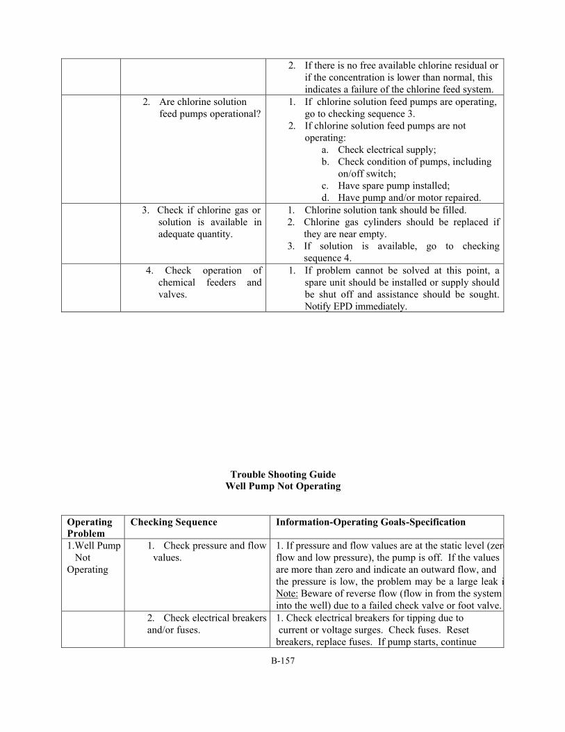
B-157
2. If there is no free available chlorine residual or if the concentration is lower than normal, this indicates a failure of the chlorine feed system.
2. Are chlorine solution feed pumps operational?
1. If chlorine solution feed pumps are operating, go to checking sequence 3.
2. If chlorine solution feed pumps are not operating:
a. Check electrical supply; b. Check condition of pumps, including
on/off switch; c. Have spare pump installed; d. Have pump and/or motor repaired.
3. Check if chlorine gas or solution is available in adequate quantity.
1. Chlorine solution tank should be filled. 2. Chlorine gas cylinders should be replaced if
they are near empty. 3. If solution is available, go to checking
sequence 4. 4. Check operation of
chemical feeders and valves.
1. If problem cannot be solved at this point, a spare unit should be installed or supply should be shut off and assistance should be sought. Notify EPD immediately.
Trouble Shooting Guide Well Pump Not Operating
Operating Problem
Checking Sequence Information-Operating Goals-Specification
1.Well Pump Not Operating
1. Check pressure and flow values.
1. If pressure and flow values are at the static level (zeroflow and low pressure), the pump is off. If the values are more than zero and indicate an outward flow, and the pressure is low, the problem may be a large leak in the syNote: Beware of reverse flow (flow in from the system into the well) due to a failed check valve or foot valve.
2. Check electrical breakers and/or fuses.
1. Check electrical breakers for tipping due to current or voltage surges. Check fuses. Reset breakers, replace fuses. If pump starts, continue
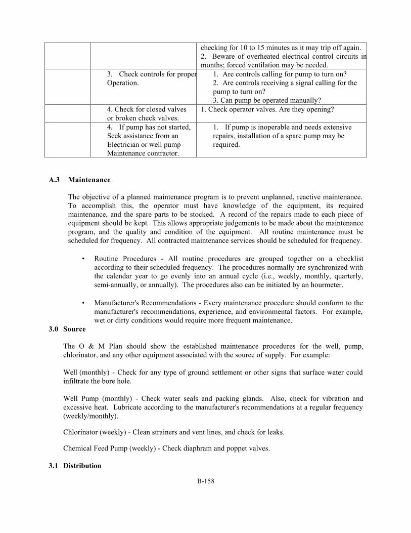
B-158
checking for 10 to 15 minutes as it may trip off again. 2. Beware of overheated electrical control circuits in hot summer months; forced ventilation may be needed.
3. Check controls for properOperation.
1. Are controls calling for pump to turn on? 2. Are controls receiving a signal calling for the pump to turn on? 3. Can pump be operated manually?
4. Check for closed valves or broken check valves.
1. Check operator valves. Are they opening?
4. If pump has not started, Seek assistance from an Electrician or well pump Maintenance contractor.
1. If pump is inoperable and needs extensive repairs, installation of a spare pump may be required.
A.3 Maintenance
The objective of a planned maintenance program is to prevent unplanned, reactive maintenance. To accomplish this, the operator must have knowledge of the equipment, its required maintenance, and the spare parts to be stocked. A record of the repairs made to each piece of equipment should be kept. This allows appropriate judgements to be made about the maintenance program, and the quality and condition of the equipment. All routine maintenance must be scheduled for frequency. All contracted maintenance services should be scheduled for frequency.
• Routine Procedures - All routine procedures are grouped together on a checklist
according to their scheduled frequency. The procedures normally are synchronized with the calendar year to go evenly into an annual cycle (i.e., weekly, monthly, quarterly, semi-annually, or annually). The procedures also can be initiated by an hourmeter.
• Manufacturer's Recommendations - Every maintenance procedure should conform to the
manufacturer's recommendations, experience, and environmental factors. For example, wet or dirty conditions would require more frequent maintenance.
3.0 Source
The O & M Plan should show the established maintenance procedures for the well, pump, chlorinator, and any other equipment associated with the source of supply. For example:
Well (monthly) - Check for any type of ground settlement or other signs that surface water could infiltrate the bore hole.
Well Pump (monthly) - Check water seals and packing glands. Also, check for vibration and excessive heat. Lubricate according to the manufacturer's recommendations at a regular frequency (weekly/monthly).
Chlorinator (weekly) - Clean strainers and vent lines, and check for leaks.
Chemical Feed Pump (weekly) - Check diaphram and poppet valves. 3.1 Distribution
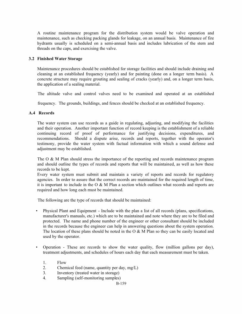
B-159
A routine maintenance program for the distribution system would be valve operation and maintenance, such as checking packing glands for leakage, on an annual basis. Maintenance of fire hydrants usually is scheduled on a semi-annual basis and includes lubrication of the stem and threads on the caps, and exercising the valve.
3.2 Finished Water Storage
Maintenance procedures should be established for storage facilities and should include draining and cleaning at an established frequency (yearly) and for painting (done on a longer term basis). A concrete structure may require grouting and sealing of cracks (yearly) and, on a longer term basis, the application of a sealing material.
The altitude valve and control valves need to be examined and operated at an established
frequency. The grounds, buildings, and fences should be checked at an established frequency.
A.4 Records
The water system can use records as a guide in regulating, adjusting, and modifying the facilities and their operation. Another important function of record keeping is the establishment of a reliable continuing record of proof of performance for justifying decisions, expenditures, and recommendations. Should a dispute arise, records and reports, together with the operator's testimony, provide the water system with factual information with which a sound defense and adjustment may be established.
The O & M Plan should stress the importance of the reporting and records maintenance program and should outline the types of records and reports that will be maintained, as well as how these records to be kept. Every water system must submit and maintain a variety of reports and records for regulatory agencies. In order to assure that the correct records are maintained for the required length of time, it is important to include in the O & M Plan a section which outlines what records and reports are required and how long each must be maintained.
The following are the type of records that should be maintained:
• Physical Plant and Equipment - Include with the plan a list of all records (plans, specifications, manufacturer's manuals, etc.) which are to be maintained and note where they are to be filed and protected. The name and phone number of the engineer or other consultant should be included in the records because the engineer can help in answering questions about the system operation. The location of these plans should be noted in the O & M Plan so they can be easily located and used by the operator.
• Operation - These are records to show the water quality, flow (million gallons per day),
treatment adjustments, and schedules of hours each day that each measurement must be taken. 1. Flow 2. Chemical feed (name, quantity per day, mg/L) 3. Inventory (treated water in storage) 4. Sampling (self-monitoring samples)
B-160
5. Pumping (pumps used and hours of operation) 6. Physical/chemical water quality
a. Chlorine residuals b. pH c. Water temperature
Operating record sheets are forms which allow the records described above to be maintained in an organized, tabular form. A small groundwater system may need only one or two simple monthly operating record forms to maintain operating information for an entire month. Operating forms prepared by EPD must be used for compliance reporting to EPD each month.
• Preventive Maintenance - Preventive maintenance records are needed to provide accurate
documentation of maintenance work on repairs which have been done on water system equipment. These records are useful for budgets and when purchasing equipment.
• Operating Costs - It is important to maintain accurate records of water system operating costs
because these records may be used to help plan future operating budgets, justify water rate increases, evaluate water system expenditures, and compare costs from one year to the next.
• Emergency Conditions - Documentation of emergency conditions, as well as the actions taken in
response to the emergency, should be compiled for each significant emergency and filed into the water system records. As an example, an Emergency Conditions Report for flooding of the treatment plant should include the following:
1. Time of notification of the impending flooding; 2. Actual time flood water entered the treatment plant site; 3. Measurement of highest water level in relation to the physical structures at the treatment
plant; 4. Location where water first entered the plant;
5. Equipment and/or structures damaged by the flood. Was the equipment shut down. Record time and date;
6. Reports of maximum flood stage of the receiving stream; 7. Protective actions taken by plant personnel; 8. Other organizations or agencies contacted and actions taken by them; 9. Length of time and degree to which water quality was affected. Include documentation
of all customer complaints noting date and time and the follow-up actions; 10. Description of repairs and/or replacements required to restore plant to original condition.
Record time, cost, and date of restoration of each unit; 11. Contractor, repair service, or equipment vendor involved in repairs/replacements,
together with the individual who represented the company;
B-161
12. Actions taken to prevent reoccurrence of emergency condition. Recommendations for
revisions to Emergency Response Plan and capital improvements.
This information could be necessary if insurance claims arise as a result of a particular emergency condition.
• Notification - When public notification is required, it is important from a legal and management
standpoint that records of the notification are kept, including dates of notification, procedures used to abate the condition, follow-up test results, and date notification advisory was lifted. Keep records of all correspondence, and all contacts with local and state agencies regarding the emergency situation.
To prevent the loss of records through flood, fire, or other disaster, a spare copy should be on file at a second location. The O & M Plan should specify where a copy of the records is located.
A.5 Sampling and Compliance Monitoring
One primary responsibility of the public water supply operator under the Safe Drinking Water Act (SDWA) is the routine sampling and testing of the treated water quality to assure that the water being served does not present a health risk to the consumer.
This part of the O & M Plan should outline the procedures for properly sampling and monitoring, including locating and collecting samples, as well as obtaining certified laboratory services.
5.0 Sampling and Analysis
Sampling is the first step in any water quality analysis program; therefore, it is important to develop a sampling program which provides accurate representation of the quality of the water being sampled. This can be accomplished by establishing sample dates, times, and locations so that they truly represent system conditions and by the implementation of a sound quality assurance program.
A. Scheduling - The O & M Plan should include a yearly sampling schedule which clearly
outlines what samples should be collected and on what days to assure that the proper samples are collected and analyzed on time. The schedule also should identify sampling locations. This information can then be entered into a table prepared by the system.
The basic sampling schedule for each water supply will be determined largely by the routine monitoring requirements of the drinking water regulations. The operator should review these requirements, establish a sampling schedule to meet them, and enter the schedule into the table. The sampling schedule, once established, should be updated annually to accommodate schedule or sampling location changes.
Future amendments to the regulations will result in additional monitoring requirements. Therefore, it is important for the water supplier to keep in contact with EPD and be informed about the new requirements so the sampling schedule can be updated to reflect the changes.
The following factors should be considered when developing a sampling schedule:
B-162
1. Microbiological samples should not be scheduled to be collected all in one day.
Rather, they should be spread out over the month so that the samples are representative of bacteriological conditions within the system during the entire month;
2. Chlorine residuals should be taken concurrently with the microbiological samples.
Chlorine residuals will probably be taken more frequently in accordance with EPD's recommendations.
3. Coliform sample collection should not be scheduled for Fridays. The laboratories
would not begin the coliform analysis until Monday, and by then, the sample would be too old;
4. Schedule sampling so that samples which must be analyzed immediately are not
delayed in transit while other samples are being collected. B. Location
Once the required type, number, and frequency of sampling has been determined, the specific location of sample points must be selected and incorporated into the O & M Plan. The main objective in sample point selection is to choose points which will provide samples that are truly representative of the type of water to be analyzed. This section outlines sample point selection guidelines and the distribution system sampling. It also discusses how the selected sample point locations may be made a meaningful part of the O & M Plan.
1. Raw Water Sampling
Groundwater (Wells) - Raw water samples may be collected from a sample tap installed on the well discharge line at a point prior to any chemical additions or treatment processes.
2. Distribution System Sampling
Although distribution system sample point selection is somewhat judgmental, as a minimum, the points selected must be representative of each different source entering the system and of conditions within the system. Also, sample points must be located according to the requirements of the SDWA.
a. Sample Location Selection
The largest number of samples collected from the distribution system will be used to test for coliform bacteria and chlorine residuals. The point selected for collection of these samples should be as representative of all sources as possible. Exact sampling points for disinfection by-products (DBPs), volatile organic compounds (VOCs), inorganics, and radionuclides should be acceptable to EPD. Generally, the sampling location for most tests will be the entry point to the distribution system and representative of each source.
B-163
When selecting bacteriological sample point locations, the following factors should be considered:
• Sample points should be uniformly distributed throughout the system; • Sample points should be located so that water flowing from storage
tanks may be sampled, rather than water flowing into the tanks; • For systems having more than one water source, sample points should
be located in relative proportion to the number of people served by each source and should be representative of water from each source;
• The locations of sampling points should be changed annually so that a better representation of system conditions can be achieved.
b. Sample Point Selection
Once representative sample points have been located in the distribution system, specific sample faucets must be selected. The following guidelines may be useful in the selection of sample faucets:
• The selected taps should be a cold water faucet closest to the point where
the water main enters the house; • Samples should not be taken from drinking fountains, swivel faucets,
faucets with strainers, leaking faucets which permit water to run over the outside of the faucet, or houses with home water treatment units, including softeners. Faucets which are dirty or are in areas with excessive dust, smoke, or other sources of contamination should be avoided.
Once each representative sample point has been selected, it should be entered into the sampling schedule along with a description of the location and it should be assigned a sample point number. Each point should be plotted on a copy of the distribution system map. This map then should be included in the O & M Plan.
C. Quality Assurance
The result of any analysis or water parameter measurement is no better than the sample used. Guidelines for proper sample collection, handling, preservation, transportation, and storage techniques are essential to a monitoring program. It is important that these procedures be included in the O & M Plan so that water system personnel responsible for collecting and analyzing samples have a quick reference available to them .
D. Laboratory Services
The SDWA requires that all sample analyses to be used for determination of compliance with the monitoring requirements must be performed by a laboratory which has been certified by EPD.
The water suppliers may wish to retain the services of a certified private laboratory. The laboratory which performs the analyses must record the results on the standardized reporting forms which are then submitted to EPD and to the water supplier within 10 days of the end of a monitoring period. The laboratory also is responsible for contacting the water supplier whenever it receives
B-164
unacceptable samples or if an MCL has been exceeded, and is responsible for notifying the department in writing within 24 hours after an MCL is exceeded or check samples are required.
Water systems may have the option of contracting with the EPD Laboratory to perform the entire monitoring and reporting procedure, or to provide whatever combination of laboratory services the water supplier wishes.
It is, ultimately, the water supplier's responsibility to assure that the proper samples are collected and analyzed, and that the results are reported to the proper parties in a timely manner. Therefore, regardless of who performs the sampling, analyses and reporting procedures, the operator should establish the sampling and analysis schedule, forward a copy to the lab, and maintain a copy in the O & M Plan so that the entire sampling and analysis program may be monitored effectively. The name, address, and phone number of the responsible laboratory should be included in the O & M Plan as well as a detailed outline of the services which the outside laboratory is responsible for providing and the duties which are the responsibility of the water supply.
E. Sample Collectors
The persons designated to do the sampling have to be trained in proper sample collection, preservation, and recordkeeping techniques. Refresher training on proper sampling techniques should be provided periodically to assure that correct procedures are being used.
The sampling schedule should include the name(s) of the person(s) responsible for the collection of each sample, as well as that of a backup sampler in the event of illness, etc. This will assure that all samples are collected on schedule.
5.1 Compliance Monitoring
Once the samples have been properly collected and the analyses have been completed, the results of these analyses must be interpreted and decisions made based on these interpretations. Resampling may or may not be required, records must be maintained, and notifications to EPD and water system management may or may not be needed.
There should be one person responsible for overseeing and coordinating all aspects of the water quality monitoring program for the water system. The responsibilities of the program coordinator would include schedules, training, assignment of personnel, laboratory coordination, notification. keeping records. interpreting results, check samples, reporting to DEP and management, and review of program.
A. Interpretation of Results
Once the water quality analysis results have been received, they must be reviewed to determine what follow-up actions are needed. When the analysis of a sample shows that an MCL has been exceeded, check sampling is required to confirm the routine sample results and to provide a safeguard against sampling or lab error. The department also must be notified, as should the water system management personnel.
The interpretation of analysis results extends beyond determination of compliance with the regulations to the monitoring of the routine operation of the water system. It is a key
B-165
responsibility of the coordinator to see that all water analyses are reviewed and interpreted to identify any operation and maintenance modifications, changes in chemical feed points or rates, or additions or changes to the treatment processes that may be needed.
B. Notification
The water system personnel also are responsible for assuring that all necessary notifications, both to EPD and to water system management, are made within the required time periods.
1. The reporting to EPD, as they relate to the water quality program, are as follows:
a. Routine sample reporting
The results of any test required by the regulations must be reported within the first 10 days of the month following the end of the monitoring period, or within 10 days after they are received, whichever is sooner. This allows data for each month to be summarized and sent in at one time, instead of submitting each individual test result immediately after it is received. Even if it is a contract laboratory's responsibility to report the routine sample results; the water supplier should follow up on the samples to confirm that the results have been reported on time.
b. Check sample and violation reporting
Generally, any sample result which exceeds an MCL must be reported to EPD by the supplier within one hour, as must the results of check samples which confirm the presence of a contaminant. Furthermore, the supplier must report any failure to monitor to the department within 48 hours. In all cases, public notification also is required.
The O & M Plan should provide a handy reference to the EPD's reporting requirements, as well as of the procedures to be followed to meet them, and should include the name, address, and phone number of the EPD contact person, including an emergency phone number which will be answered 24 hours a day.
2. The management of the water system should be advised whenever circumstances require
check sampling, EPD notification, or public notification. A water system policy on notification of management should be established and incorporated into the O & M Plan so that the proper action may be taken in any given situation. This policy should include:
a. A table or flow chart (or both) summarizing what situations require notification,
who should be notified in each case, and when they should be notified (i.e., prior to or following EPD notification);
b. The phone numbers, both home and office, of each person to be contacted. C. Recordkeeping
B-166
A procedure for maintaining accurate sampling and reporting records should be established. All employees who are responsible for the sampling and reporting programs should be provided with training on proper records maintenance procedures.
1. Sample Records
The following are some suggested guidelines for procedures in keeping accurate sample records which, in turn may be included in the O & M Plan:
a. Each sample bottle should be assigned a number which corresponds to a
number on a recordkeeping form that is maintained as a permanent part of the water supply's records;
b. Each sample bottle should be affixed with a label or tag which includes the
following information:
• Sample number, • Date sampled, • Time sampled, • Location sampled, • Type of sample (i.e., routine, check, special purpose, etc.), • Sample collector, • Chlorine residual (recommended whenever coliform tests are taken);
c. The information on the label then should be entered on the sample record form; d. A copy of a sample label should be included in the O & M Plan, as should a
copy of the sample record form and sample recordkeeping instructions. 2. Reporting Log
A reporting log should be developed and also should be maintained to keep a record of all incidents which required some type of notification. This log should be maintained as a permanent part of the water system's records. Also, copies of any written or published notification should be maintained in the permanent records as well. Some recommended items to be included on the reporting log are as follows:
a. Date of notification;
b. Type of notification (i.e., EPD, management, public, etc.); c. Time of notification; d. Person contacted; e. How notified (i.e., telephone, in writing, newspaper, etc.);
f. Reason for notification (i.e., failure to monitor, MCL violation, treatment technique,
etc.)
B-167
• What, specifically, was reported, • Response of the person notified (i.e., specific directions, advice, or instructions);
g. Follow-up action (if applicable); h. Comments. A.6 Public Notification
One of the most important provisions of the Safe Drinking Water Act is the requirement that the water supplier notify its customers when the system is in violation of the regulations. Public notification is required to protect consumers from water that may be temporarily unsafe. If used properly, public notification also can increase public awareness of problems that the water system faces and the costs of supplying safe drinking water.
6.0 Content of Notification
Since specific details of an actual public notice will vary depending on the circumstances, it is difficult to have specific notices prepared ahead of time and ready for use when needed. Therefore, it is important to have available all the information needed to prepare a notice when the occasion arises and to have some sample notices on hand. The basic elements of a good public notice should be outlined and placed in this chapter of the O & M Plan so that it will be readily accessible.
A. Information to be Included Generally, a public notice which fully informs users should include: 1. Who - The name of the water system;
2. What - The purpose of the notice, (i.e., the violation, variance, or exemption); 3. When - The date the violation was observed;
4. Authority - The name of the government agency that established the regulation;
5. Regulation Involved - A description of the standard, such as the MCL for
nitrates; 6. Health Significance – Mandatory EPA health effects language for VOCs and
other contaminants are to be used; 7. Precautions to be Taken - (i.e., boiling water in the case of a serious
microbiological MCL violation);
8. Steps Being Taken to Correct - A description of what actions are being taken by the water supplier to correct the problem, such as searching for an alternate source of supply;
B-168
9. Alternatives - Where the customers can obtain an alternate supply of water, if necessary.
6.1 Advance Preparations
While public notices cannot be written ahead of time, some arrangements for issuing them can be made in advance and incorporated into the O & M Plan so that when public notification is required, the process can proceed in a smooth and timely manner.
A. Media Notification
1. Television, Radio, and Newspapers
a. Determine in advance what radio and television stations broadcast to the area served by the water system.
b. Find out who the contact person at each station is and establish
good communications. Include in the O & M Plan the name, address, phone number, and contact person at each station. Inform them of the requirements, advise them of what would be involved on their part, and request information on what the water supplier would need to do in the event that public notification is required.
B. Direct Notice
Because direct notice to the consumers is required under any circumstance, planning ahead is vital so that the notices can be written, printed, and mailed within the required time frames. Therefore, the O & M Plan should include a billing schedule, so that the determination of whether the notice may be sent with the next bill, whether it must be sent separately may be made; and or whether alternate methods of public notification (i.e., hand delivery or posting in public areas) must be done.
A.7 Staffing and Training
7.0 Staff
The staff of the small groundwater system usually is determined by the size and the amount of revenues which are available for operation of the water system. The very small water system often is operated by one or two employees who must be capable of performing all types of functions. List on the O & M Plan each employee's name, title, experience, and certification.
7.1 Training
Training of the staff in all areas of operations usually will benefit the system and the customers in improved and more economical service. This is especially important when a
B-169
one or two-person staff must be capable of performing all functions on the system and to meet the operator certification requirements.
In addition to the requirements for certification, training is available in the areas of hydraulics, mechanics, chemistry, electricity, electronic controls, pump maintenance, chemical feeder maintenance, and system controls operation and maintenance. Courses in human relations, accounting, budgeting, and planning also may be helpful. Training courses and seminars are available through industry organizations (i.e., AWWA, GRWA, GWPCA, etc), the state, equipment manufacturers and colleges.
A.8 Sanitary Survey Program
8.0 General
Water systems must have a sanitary survey conducted of their systems as often as possible, but, at minimum, as frequently as required by the regulations. A sanitary survey is a systematic review of the entire water system facilities to determine if there has been any change in the condition of the land, buildings, water source, treatment process, equipment, or the surrounding area. Any change, from one survey to the next, should be recorded on the sanitary survey form and must be evaluated for its impact on the water system. For example, the deterioration of buildings or equipment can threaten the system's capability to provide quality water and can mean increased maintenance or replacement of facilities. Also, construction of residential, commercial, or industrial facilities near the sources of supply could affect the raw water quality.
For additional information about the sanitary survey requirements and the format used, contact EPD offices.
A.9 Safety Program
9.0 General
Every water system, regardless of size, needs to develop and implement a safety program to prevent injury to its employees and to avoid accidents involving the public. The development of a safety program should include information regarding potential job hazards, preventive safety measures, proper safety and emergency procedures for the use and operation of tools and equipment, and the proper methods of handling and reporting accidents and injuries. One person should be designated the responsibility for overseeing and maintaining the safety program.
9.1 O & M Safety Plan
The O & M Plan should list procedures which have been established as part of the water system's safety program which identifies and describes water system hazards and provides safety measures.
The following sections will not outline the exact safety procedures that should be written in the O & M Plan. Rather, it will serve as a guide for recommended job activities for which
B-170
safety procedures should be established and listed in the O & M Plan, as well as other general topics related to the safety program.
A. Identification and Description of Hazards
The safety hazards associated with water supply systems are numerous and varied. Water system personnel should be made aware of all hazards, where these hazards are present in the water system, and how they may affect the employees. The following list identifies some of the general hazards faced by water system employees:
1. Bodily injury caused by falls, improper lifting, improper use of tools and
equipment, and accidents involving moving mechanical equipment; 2. Electrical shock and bums; 3. Injury caused by improper chemical handling; 4. Exposure to chlorine gas; 5. Injury caused by improper entrance into confined spaces; 6. Trenching and shoring cave-ins; 7. Electrical shock while changing meters.
The O & M Plan also should include a detailed description of each hazard, including where each hazard may be present and what the health risk from each hazard may be to the employee.
B. Recommended Safety Program
Once the job hazards have been identified and described, it is important to outline the proper safety procedures which should be used when performing each job task to reduce these hazards as much as possible. Therefore, the O & M Plan should provide detailed safe operating procedures for specific aspects of water system employee job responsibilities. Recommended safety procedures for each of these water system job tasks can be found in the American Water Works Association's (AWWA's) Manual M3, Safety Practices for Water Utilities, as well as in other reference materials on water supply system operation. Manufacturer's literature also may be a good source of safety procedures for some of the tools, equipment, and machinery.
C. Personal Protective Equipment
The type of personal protective equipment required for each job activity should be outlined. When the wearing of personal protective equipment is specified, it should be made mandatory. The types of personal protection equipment that should be discussed are:
1. Face and eye protection;
B-171
2. Hand protection;
3. Body protection;
4. Head protection;
5. Foot protection;
6. Respiratory equipment;
7. Safety belts.
D. Chemical Handling and Storage
Water supply system personnel are responsible for handling a variety of chemicals, the nature of which depends on the complexity of the water system. In a simple well system, hypochlorite solution may be the only chemical used.
Regardless of the size or complexity of the system, it is important that the employees responsible for handling chemicals are well informed and thoroughly trained in the proper handling and storage procedures for all chemicals used in their particular water treatment process.
E. Right-to-Know Act
A separate section of the O & M Plan, preferably the section immediately before or after the chemical handling section, should be devoted to the Right-to-Know Act. This section should outline the water system's responsibilities as a result of its enactment, and how the supplier complies with the act.
F. Accident and Injury Response and Reporting
Because accidents do sometimes happen even when safety procedures are followed, the safety program also should include a section which provides guidance on procedures which should be followed in the event of an accident or injury. This section should include procedures on accident response, first aid, and accident and injury reporting.
Prepare instructions on procedures to follow when an accident happens, such as who should be notified, administration of first aid and reporting requirements. Include telephone numbers of the supervisor, fire department, ambulance, police department, physician, and poison center.
G. Training
All employees should be encouraged to become trained in the administration of first aid and cardiopulmonary resuscitation (CPR) and advised of where such training is available.
B-172
A.10 Emergency Response Plan
10.0 General
Each water system should develop an Emergency Response Plan to prepare for those unexpected emergencies which will at some time occur. It should be prepared to reflect the actual facilities, equipment, personnel, and circumstances for each particular water system.
TECHNICAL INFORMATION A.11 Sources of Supply
11.0 Wells
Wells are a very common source of supply for small water systems. Wells should be constructed, tested, and operated in accordance with the water works permit and any restrictions imposed by regulatory agencies such as river basin commissions.
A. Records
1. Records of the water levels in the well should be recorded frequently. The water level in the well can be observed by inserting a probe into the well which registers when contact with water is made. Continual water level readings can be obtained by employing an air line in the well and a recorder. Air lines do break after a period of time, so sudden changes in the readings or no readings can indicate a damaged air line. Usually the pump has to be removed from the well to replace the air line. Adequate long-term records of flow and level will document the conditions of the aquifer and show the effects of drought, cold weather, and pumping from other nearby wells.
2. Records of the water withdrawn should be monitored by a meter. If the
meter has a flow recording device, the rates of flow as well as the total flow can be observed. If a recorder is not available, the operator can time the meter for a specific period to determine the rate of pumping. The amount of water pumped is necessary for monthly and/or semi-annual production reports. Careful comparison of the water pumped
B-173
and the well levels usually can detect wear on the pump. This could provide a warning of possible pump failure.
B. Pumps
1. The types of pumps normally used in wells are submersible or vertical turbine. The vertical turbine pumps have the motor mounted on the discharge head and the pump is driven by a shaft. Shafts may be open or enclosed. Enclosed shafts are lubricated by oil; open shafts are lubricated by the water.
2. Maintenance of well pumps usually is performed by the well drilling
contractor who has the equipment to pull the pump from the well to work on it. Submersible pumps require no routine maintenance by the operator.
Maintenance of a vertical turbine pump consists of checking the packing gland where the shaft comes through the casing. Packing glands should be checked frequently and never tightened to the point where there is no leakage, since this will cause premature packing wear. When the packing wears or when the gland cannot be tightened any further, a new set of rings should be installed. Other maintenance of vertical turbine pumps is the lubrication of the shaft, if required, and lubrication of the electric motor.
C. Well Bore Maintenance
The yield of the well can be affected by rock fractures, a damaged or clogged well screen, or other causes. The compilation of water level and pumping records provides information which can be evaluated by a qualified hydrogeologist.
D. Water Quality
An analysis of the well water quality should be made annually (at least at intervals required by the regulations) and the results should be compared to the previous results to determine if there is any change in the water quality. This information should be recorded with the sanitary survey. A change in quality can indicate over-pumping of an aquifer, possible pollution or contamination of the source, and the need for additional treatment.
A.12 Treatment
Treatment of the raw water is necessary in water supplies to prevent the transmission of contaminants to the consumer. The contaminants could be toxic, cause disease, or have other long-term health effects for the consumer. Water also must be treated for aesthetic contaminants (i.e., color, taste, odor, and corrosivity) so that the consumer continues to have trust in the quality, taste, and odor of the drinking water. Because of this trust, the water supplier and operators have
B-174
a continuing challenge to provide water of the highest possible quality at a time when there is an ever increasing possibility of contamination.
12.0 Disinfection
A. General
The disinfection of water is the selective destruction of pathogenic organisms. The destruction of pathogenic organisms is the destruction of all disease-causing organisms. The total coliform group merits consideration as an indicator of pollution because these bacteria always are present in the normal intestinal tract of humans and other warm-blooded animals. Large numbers of coliform bacteria are associated with fecal wastes. Thus, the absence of total coliform bacteria is evidence of a bacteriologically-safe water.
B. Chemicals
The chemicals used for disinfection are chlorine, calcium hypochlorite, and sodium hypochlorite. There are other chemicals (i.e., iodine, bromine, and ozone) which will disinfect water, but not commonly used in water treatment.
1. Chlorine a. General Description
Chlorine is a greenish-yellow gas which has a very penetrating, acrid odor that burns the eyes and the throat. Chlorine gas is two and one-half times heavier than air and, therefore, tends to collect in low areas such as pits, basements, and sumps. Chlorine gas is supplied under pressure in 100 or 150 lb. cylinders or in 2000 lb. containers.
The chlorine cylinders must be protected from exposure to heat because a rise in temperature can cause an increase in pressure which could rupture the steel cylinders. The cylinders are equipped with a fusible plug which softens and melts at 1580F to 1650F to prevent the buildup of pressure.
Chlorine cylinders must be secured in an upright position to prevent failing over and damaging the valve. Also, the valve should be protected with a protective cap when not actually in use.
b. Method of Feeding
The chlorinators used to feed the chlorine are vacuum controlled so that the chlorine gas only can be released when a vacuum is present. The chlorine gas then is injected into a stream of water at the injector. The flow of water through a small orifice in the injector creates the vacuum which draws the chlorine gas
B-175
into the stream of water. The solution of chlorine and water then is conveyed to the point of application.
A typical chlorinator has a pressure-reducing valve to reduce the chlorine gas pressure, a rate valve and rate meter to control the rate of flow, and a valve which shuts off the supply of chlorine gas when a vacuum is not present.
c. Determination and Control of Feed Rate
The amount of chlorine applied to the clear well, or point of discharge to the distribution system, should provide a detectable residual of free chlorine in the recommended amount of at least of 0.2 mg/L at all parts of the distribution system. This may require a feed rate of 1 to 2 mg/L at the clear well due to long transmission mains and distribution storage facilities. Where chlorine is added at points in the distribution system, the goal also is to maintain a detectable (recommended amount of 0.2 mg/L) chlorine residual in the distribution system. This may require the application of 0.5 to 1.0 mg/L.
The rate of feed in a gas chlorinator is controlled by a flow rate adjusting valve, and a rate meter indicates the rate of flow. In some installations, there may be chlorine residual monitoring equipment which automatically paces the rate of feed to maintain a specific chlorine residual at a specified location downstream from the point of application.
d. Precautions and Abnormal Situations
• Chlorine gas is extremely toxic and can cause death when inhaled. All safety precautions must be observed.
• Exhaust fans should be used to ventilate the chlorine room in the event of a leak. Ideally, fans should push air into the room from the ceiling or a high point on a wall and the exhaust must be from the floor level. This prevents the chlorine gas from passing over the fan and motor. Chlorine gas is very corrosive, and can damage the fan and the motor.
• Self-contained breathing apparatus is to be used if there is any suspicion of a leak.
• Chlorine leaks can be checked by use of a rag on a stick dipped in ammonia. When passed near the chlorine leak, a white vapor will form.
• When a leak is suspected, always work with a backup person to help you out if you are overcome.
• When a leak cannot be repaired and could become a threat to the area, contact the fire department for help.
• If a chlorine cylinder or container is leaking, call the supplier for help. • Avoid drawing more than 40 lbs. of chlorine per day from any one cylinder.
If more chlorine is required, the withdrawal should be from multiple cylinders manifolded together.
2. Calcium Hypochlorite and Sodium Hypochlorite
a. General Description
B-176
Calcium hypochlorite is a dry, white chemical in granular or tablet form. When used for disinfection, it should be mixed in a solution of water and fed by solution pump into the water to be treated.
Sodium hypochlorite is a light yellow liquid which is commonly used as bleach; however, the concentration of sodium hypochlorite used in water treatment is much higher (up to 15 percent). The liquid usually is supplied in five-gallon carboys; however, some smaller systems purchase one-gallon containers.
b. Method of Feeding
Both calcium hypochlorite and sodium hypochlorite solutions are fed by means of a metered solution pump. The powder or the liquid is diluted with water in a solution crock to a predetermined strength, usually about a one percent solution.
c. Determination of Feed Rate
The amount of calcium hypochlorite or sodium hypochlorite applied to the water is determined by the free chlorine residual which is necessary to provide adequate disinfection of the water and maintain a detectable residual in the recommended amount of at least 0.2 mg/L at any point in the distribution system. Each system will have developed criteria to determine the necessary chlorine residual at the point of application. However, the temperature, pH, and any organic substances in the water must be considered when setting application rates.
d. Precautions and Abnormal Situations
• Calcium hypochlorite is a dry powder which does not fully dissolve in water; therefore, a sediment of undissolved chemicals is present in the bottom of the solution tank. Because of this, the pump suction line should be kept off the bottom to prevent this sediment from being drawn into the pump.
• The hypochlorite solutions are very corrosive and should not be in contact with metals.
• The hypochlorite solutions are very strong alkali bleaches which can be a skin irritant. The eyes should be protected from solution splashes or airborne powder (dust).
12.1 Corrosion Control
A. General
Water sometimes is unstable due to low pH, high level of dissolved oxygen, and low alkalinity. This results in chemical reactions causing tuberculation which is the buildup of corroded materials on the inside of the pipes. This buildup reduces the cross-sectional area of the pipe and available flow. The roughness of the buildup requires more energy, increasing pumping costs.
B-177
The corrosivity in water usually is evidenced by the visual observation of the effects of corrosion on metal pipes when they are excavated for repairs or replacement. Customer complaints of dirty water is another indication of corrosive water. Records of customer complaints, plotted on a system map, can help locate the problem. If the Langelier Index indicates a corrosive water, a further study by an engineer will confirm or deny the condition. The engineer will probably have additional tests performed such as dissolved oxygen and marble tests. The engineer also may have special steel specimens called "coupons" inserted into the water mains at various locations in the system. After a period of time, usually several months, the coupons are removed and examined for loss of weight and corrosion. The examination of the results of these tests will enable the engineer to evaluate the corrosivity of the water throughout the system and make recommendations for treatment procedures.
Corrosion can cause metals in the pipe materials, (i.e., iron, lead and copper) to deteriorate and go into solution. These metals carried by the water are then consumed by the customer. The iron in the water usually is noticeable in rust stains on clothing. Lead in drinking water is not noticeable to the consumer, but present in concentrations higher than the action level, is a health hazard.
B. Cause
Corrosion in pipes is caused by reactions between water and the metal in the pipe. This appears as rust and tuberculation (buildup of rust). Some of the factors which affect the rate of corrosion are:
1. Temperature - Higher temperatures cause more rapid chemical reactions (i.e., reactions
which occur inside hot water tanks); 2. Low pH; 3. Low alkalinity;
4. Velocity - Corrosive water at high velocity causes rapid pipe deterioration but shows little metal pickup. Low velocity with more contact time will have more metal pickup resulting in red water,
5. Galvanic corrosion - When two different metals come into contact, there is a chemical
reaction which produces a flow of electrons from one metal to the other, causing corrosion;
6. Dissolved gases - Oxygen increases the rate of corrosion. Carbon dioxide reduces pH
and increases corrosion. Nitrogen tends to lower corrosion rates.
C. Tests
The tests which are used to monitor the corrosivity of the water are temperature, pH, alkalinity, dissolved oxygen, and hardness. The results of these tests can be used to calculate a Langelier Index (LI) for the water. If the LI has a negative value, the water is aggressive. A value of -1.0 to -2.0 indicates the water is moderately aggressive and a value greater than
B-178
-2.0 means the water is highly aggressive. A value of zero or a positive value indicates the water is nonaggressive and will tend to form a scale on the pipes. The calculation of the Langelier Index should be made by a qualified laboratory on a quarterly basis. The laboratory also should determine, for the water system, the correct ranges of pH and alkalinity to produce a water which is nonaggressive.
Based on the information provided by the results of these tests, the water system can then determine what chemicals and what feed rates are necessary to provide nonaggressive water.
A.13 Distribution
The distribution system includes the conveyance of water from the source to the customer including pumping, transmission mains, distribution mains, valves, fire hydrants, customer service lines, and distribution system storage. The water must be delivered in the same potable, ready-to-drink condition that it left the treatment facility. To protect the water quality, the water distribution workers must at all times protect the water from any type of pollution or degradation.
13.0 Plans and Records
A. Distribution System Maps
When water mains are installed, a plan of the pipe and fittings must be drawn to establish a record of the facilities installed. This information should be either added to the existing plans or a new plan should be started which would be referenced to the overall system plans. A system should be established for all distribution system plans so that they are of the same scale and fit together to cover the entire system.
B. Locations of Pressure Zones
On the system plans, the normal operating pressures should be indicated at typical locations such as fire hydrants and customer services. These pressures are useful in comparing operating conditions when there is a suspected leak in the system. These pressures also become a part of the pressure surveys required annually by the Safe Drinking Water Act.
Sometimes a water system must be divided into different pressure zones so that customers at higher locations have adequate pressures for the service they desire. Also, customers and water mains at lower elevations must be protected from excessively high pressures which could break mains and customers' pipes and cause damage. To establish these pressure zones, the water system may have booster pump stations which pump the water to a higher elevation or the water system may have pressure-reducing stations which reduce the high pressure to a lower, acceptable level. The pressure zones should be clearly marked on the system maps so that inadvertent flow between the zones does not occur. Also, all valves which normally should be closed to separate the pressure zones should be clearly marked on the plans as normally closed.
B-179
C. Updating and Correcting Plans
When additions or changes are made to the system, the plans should be updated and corrected. At least once per year, all original plans should be updated and new prints issued to the appropriate field personnel. The original plans should be kept in a safe location to guard against loss or damage.
D. Production and Pumping Records
A record of the amount of water produced, the chemicals used in treatment, and the water pumped should be kept for the system. These records provide a history of the operation and indicate the demands of the system and the costs of operation. A comparison of records can be used to identify suspected system problems such as increased pumping or treatment costs or possible loss of water.
The records should indicate the water in the system storage facilities so a daily system use can be developed. A system of keeping records on a month-to-date basis and a daily-average-use basis should be established so they can be compared to previous years' performance.
13.1 Distribution System Components
All materials that come into contact with the drinking water during its treatment, storage, transmission or distribution must be certified for conformance with American National Standards Institute/ National Sanitation Foundation Standard 61 (ANSI/NSF Standard 61). The pipe, fittings, valves and fire hydrants must conform with the latest AWWA Standards. In the absence of such standards, pipe meeting applicable ASTM and ANSI criteria and acceptable to the EPD may be selected.
A. Transmission and Distribution Mains
There are many materials used in transmission and distribution mains; some of the more common are as follows:
1. Cast Iron - The older pipe usually had bell and spigot joints which used
jute and lead to make a water tight joint. Because of labor and skill is needed to pour a lead joint, this type of pipe is no longer commonly used. The more modern joints for cast iron pipe and ductile iron pipe are rubber gasketed joints which provide a simple seal and can be easily installed.
2. Concrete - Concrete pressure pipe has been used for transmission mains
because of its long life. It normally is only available in larger diameters and is difficult to make connections. The joints usually are seated with an O-ring rubber gasket.
B-180
3. Asbestos Cement - Asbestos cement pipe was used extensively from 1940 to 1980 as a less expensive material. This pipe can release asbestos fibers to the water if the water is aggressive. This material is no longer installed on water systems.
4. PVC (Polyvinyl Chloride) - PVC pipe is the less expensive substitute for
the ductile iron pipe. This pipe is light in weight and easy to handle and join. It is subject to damage by exposure to sunlight, and petroleum products can penetrate the through the wall of the PVC pipe.
B. Valves
There are several types of valves normally used in transmission and distribution systems. Some are used for normal control and others have special purposes.
1. Gate Valves - Gate valves are the most commonly used valve in water
systems. These valves have proven to be most reliable and maintenance free. Maintenance should consist of exercising the valve periodically to keep the threads clear of buildup and checking the valve stem seals.
2. Butterfly Valves - Butterfly valves are frequently used for the regulation
of flow. These valves have a wafer which rotates in the water stream from fully open to fully closed. The wafer usually has a rubber gasket on its sealing edge. Maintenance consists of replacement of the gasket when it becomes worn.
3. Check Valves - Check valves are used to control the flow in only one
direction. This normally is done by having a hinged flapper which the flow of water will move out of the water flow area. When the flow of water attempts to reverse, the flapper is returned across the flow on to the valve seat stopping the flow. The movement of the flapper is caused by the reverse flow of water, exterior springs, or gravity. There are other configurations of check valves which are designed for special purposes.
4. Pressure Relief Valves - Pressure relief valves are used to bleed off a
flow of water to relieve a high pressure surge condition. Surges of water, such as from the start-up of a pump, can cause high pressures which could damage pipe and facilities.
5. Pressure Reducing or Pressure Regulating Valves - These valves are
normally used to maintain a specific pressure on the downstream side of the valve and to control the pressures in various pressure zones of the distribution system. This action is accomplished by a diaphragm which controls the position of the valve disc. These valves, because of their constant movement, require frequent maintenance to keep them working
B-181
and in adjustment. The items needing attention are the strainers, needle valves, pilot valves, and the main diaphragm.
6. Air Relief Valves - Air can cause serious pipeline problems by
restricting the flow. Air can get into the water system through pumps, packing glands, and leaking joints. These valves are installed at the high points on the system and are simple float valves which release air until the water enters the valve body and raises the float.
7. Plug or Ball Valves - This type of valve normally is used on customer
service lines. These valves are maintenance free and cause little flow resistance when fully open.
8. Globe Valves - Globe valves cause the water to flow up through an orifice. These valves are rarely used in water systems due to their resistance to flow and high maintenance requirements.
9. Altitude Valves - Altitude valves are used to control the height of water
in distribution storage tanks. These valves open when the system pressure drops and water flows out of the tank. When the system pressure increases, the water flows into the tank until the tank is nearly full. The altitude valve then closes. This valve is very similar in operation and maintenance to a pressure reducing valve. Maintenance consists of checking the strainers, diaphragms, small piping, and needle valves.
C. Fire Hydrants - Fire hydrants are used to provide access by fire fighting
personnel to the water system. Fire hydrants have an underground valve and a barrel to deliver the water to hose nozzles above the ground. Fire hydrants in Pennsylvania must be of the dry barrel type because of the danger of freezing. Dry barrel hydrants are designed to automatically drain the water from the barrel when the hydrant is shut off. Fire hydrants usually are manufactured so maintenance of the valve can be accomplished without excavation. All fire hydrants should be equipped with a gate valve on the lateral pipe leading from the water main. This valve will permit the water distribution crews to shut off the hydrant for maintenance. Fire hydrants should be flushed and checked at least semi-annually for proper operation, particularly that they shut off completely and that the hydrant barrel drains.
Flushing the hydrants also helps to clear any sediment from the distribution system. Fire hydrants require frequent maintenance because they are frequently operated, often by untrained personnel. The parts which often need attention are the valve seats, which are resilient rubber; the valve stem packing, which will leak; and the stems, which become twisted due to turning too tight.
A cooperative effort between the fire fighting personnel and the water system will help reduce hydrant damage and affect prompt repairs when needed. When a hydrant is taken out-of-service, the local fire company or municipality should be given notification. A record book should be kept specifically for hydrants taken out-of-service. It should contain information on the date the hydrant was
B-182
taken out-of service, the time, the hydrant number and location, the municipality, the employee's name who took it out of-service, the name of the person notified, the date returned to service, the time, and the person notified.
D. Blow-offs - Blow-offs are a tee and valve arrangement at locations where fire
hydrants do not adequately flush the system. These usually are dead ends or at locations which, due to topography, require frequent flushing such as at low points. These blow-offs must have their flow directed so that no damage occurs. The blow-offs must be located deep enough to prevent freezing and the discharge pipe should have a small hole drilled to permit draining of the pipe extending to the surface.
E Records - Records of the locations of all valves, fire hydrants, and blow-offs must be indicated on the system plans. Records of the operation and any maintenance performed must be kept. This information is useful in planning replacement of facilities due to age.
13.2 Pumps
Pumps are used in water systems to move water from one location to another and to add pressure to the water by pumping it to a higher elevation. The common uses of pumps in water systems are well pumps, chemical feed pumps, high service pumps, booster pumps, and fire service pumps.
A. Types of Pumps
Centrifugal pumps are the most common type of pump used in water systems. These pumps have the ability to adjust to varying head and flow conditions and are available in a wide variety of configurations manufactured to meet specific conditions.
The other type of pump used is the positive displacement pump which is used for feeding chemicals. These are either diaphragm type or piston type which delivers a measured volume with each revolution or cycle.
B. Capacities and Purposes
The capacities (flow and head) of each type of pump should be matched to its purpose. The capacity of each pump should have been specifically selected when the design of the system or the component was done by the engineer. However, as system components and uses change, so do the capacities and operating conditions for pumps. Therefore, the water system operator should know the flow and head (pressure) the pump was selected for and should periodically test the pumping unit for the present operating conditions. The operator should plot the results of the pump tests on the pump operating curve to determine if the operating point has changed from the design conditions and what the expected efficiency should be.
1. Well Pumps
B-183
Well pumps are usually of a vertical turbine configuration and have multiple stages. However, the smaller water systems that use low capacity wells are usually equipped with submersible pumps. The well pumps can be driven by a shaft extending down the column from a motor located on the surface or by a submersible motor attached directly on the pump and suspended in the well on the end of the column pipe.
Well pumps should have their capacity matched to the capacity of the well so that the well is not overpumped causing excessive drawdown of the aquifer which can cause a deterioration of the water quality. If the water is lowered to a level near the pump impellers, the pump also can be damaged. The capacity of the pump (flow and head) would have been selected at the time the well was initially pump tested and put in service. As the pumping level would lower, due to depletion of the aquifer, the head would increase and the flow would decrease. The operator should be aware of the original conditions and should monitor the pumping water level in the well through the use of an air line or level sensing equipment.
2. Chemical Feed Pumps
Chemical feed pumps usually are positive displacement type; however, they can be centrifugal. Since these pumps are comparatively small compared to other pumps and motors, operating efficiency usually is not a consideration for these pumps.
Chemical feed pumps must reliably deliver specific volumes of solutions at required pressures; any failures could affect the treatment process. For this reason, the water supplier should have spare pumps and parts for repairs available.
3. High Service Pumps
High service pumps pump the finished (potable) water from the clear well to the transmission distribution system. These pumps are usually high capacity and high head. There should be at least duplicate units for reliability.
The water pumped is clean and clear and should not produce any excessive wear on the pump parts. These pumps run for long periods of time; therefore, maintenance of bearings and shaft seals is important. The alignment between the pump and the motor also should be checked since misalignment can cause excessive wear on the pump and motor bearings.
4. Booster Pumps
Booster pumps are the same type of service as high service pumps except these usually are located at various points in the distribution
B-184
system to pump water to higher pressure zones. The operation and maintenance of these pumps would be the same as high service pumps.
5. Fire Service Pumps
Fire service pumps are the same as high service pumps or booster pumps except these pumps are set with automatic controls for start-up to meet the specific requirements of a large fire flow. These pumps are of high capacity and have only occasional use. The maintenance of these pumps must include checking the controls and actually operating the pumps to verify their reliability of service. All other maintenance is the same as a high service pump.
C. Reports of Operations and Maintenance
A record of the hours of operation for each pumping unit should be maintained. This record can be used for planning preventive maintenance of the units. A record of the maintenance and the cost of repairs will help to evaluate the units when they are being considered for repair, rebuilding or replacement.
D. Monitoring of Pumping Operations
There are many systems for the monitoring and controlling of pumping systems. These vary from very simple manual operation to complete automation. The following are examples of typical monitoring and control systems:
1. The simplest system would be a manual on/off switch with an indicating
pressure gauge and a water meter. This is typical of many small systems with a well, distribution system, and a tank. The operator usually knows the system very well and can adjust the pumping according to the system needs.
2. A system with a tank level recorder, a pressure recorder, and a flow
recorder with automatic pump operation would provide the operator with records and reliability of operation.
3. Where there are various pressure zones on a distribution system, the
operation of booster pumps is used to transfer water from one part of the system to another. This type of system requires careful monitoring and usually automatic controls. The information on the operating conditions (i.e., tank levels, system pressures, pump flows) must be transmitted to an operations control center so the operator can make decisions which will be best for the entire system.
4. There are interlocking controls which will stop the pump operation if
the water pressure on the suction side of the pump drops below a predetermined value or will shut off the pump if the discharge pressure exceeds a predetermined value. There are continuous monitors
B-185
available for chlorine residuals which have the capability of interrupting the pumping operation when certain values are exceeded or not met.
13.3 Distribution Storage Facilities
Distribution storage facilities can be in-ground earthen, concrete, brick, or steel reservoirs; above-ground steel or concrete tanks; or either standpipes or elevated. These storage facilities are all used to store treated water for use in the distribution system. The construction and design of these facilities must conform with the Georgia Rules for Safe Drinking Water, Chapter 391-3-5, and the EPD’s “Minimum Standards for Public Water Systems”.
Distribution storage has several purposes such as to provide sufficient water for peak demands which may exceed the pumping capacity, to supply large volumes of fire protection water, and to provide reliability when pumps must be removed from service for maintenance.
A. Maintenance
Maintenance of distribution storage reservoirs will depend on the type of material used for construction.
1. Steel Reservoirs or Tanks
Steel reservoirs should be painted inside and out with an acceptable paint system. The paint system used on the interior surface of the tank must be certified as meeting the NSF Standard 61 and must be acceptable to EPD. Some types of paint can transfer substances to the water which may be toxic or can cause foul tastes and odors in the water.
The paint system will protect the steel structure from deterioration and thus extend its useful life. A good paint system should last from eight to 15 years. The atmospheric conditions in the area can have an effect on the life of the paint system. For example, in industrial areas, the paint will have a shorter life and in rural areas, a longer life.
2. Concrete Tanks
Concrete tanks can be treated with a waterproofing system which will seal the surface cracks and stop any leakage, and extend the life of the structure. All materials applied must be approved by EPD as noted above. It is required that all products that come into contact with the drinking water must be certified as meeting the NSF Standard 61.
3. Ground Reservoirs
B-186
Ground reservoirs can be concrete, brick, or steel construction at ground level or below ground. Some typical installations are of concrete, masonry, or brick construction. These reservoirs must be properly constructed to prevent potential entry of any contaminants.
B. Safety Protection
Access to water system storage facilities can be a safety hazard, and proper precautions must be taken to protect the public and the employees from injury.
1. Where open storage reservoirs exist, there is the danger of someone falling into the water and drowning. These facilities should be securely fenced to prevent unauthorized entrance, and all employees working around these facilities should use life vests or other flotation devices.
2. All on steel storage tanks should terminate at a safe distance above
ground, be caged, and with a locked gate to prevent access by unauthorized personnel. All ladders should be caged for their full height or a safety harness should be provided.
3. No entrance to a tank should be made by any personnel without first
checking for dangerous vapors, fumes, or gases. Also, do not enter a tank without a safety harness and rope tended by a fellow employee from the outside of the tank.
4. Fences around all storage facilities are recommended to prevent
unauthorized access and possible vandalism. C. Storage Facilities Information
1. A record should be kept showing the location, year built and by whom, elevation at the base of the tank and the top of the overflow pipe, the size of the diameter and the height, and the capacity in gallons.
2. Painting records of the interior and exterior showing the year painted,
type of paint, and the square foot area for painting. This information will be useful when setting painting budgets.
3. Altitude Valve Records
The type and size of the altitude valve should be noted, along with the type and number of the leathers needed to make repairs, the date repairs were made, and any parts that were used.
13.4 Unaccounted-for Water
Unaccounted-for water is water which is produced but is not used or sold to the consumers. There are many factors which are considered in the determination of the percentage of unaccounted-for water. This percentage is a measure of the efficiency of the operation of the system.
B-187
A. Factors to Consider Factors to consider in the determination of the unaccounted-for water are:
1. The water produced - Is this quantity accurately deter-mined, has the meter been calibrated, and does the meter measure all of the water?
2. The water used for water system purposes such as chemical feed water,
backwash water, fire hydrant and blow-off flushing - How is each of these uses measured? Careful accounting in the treatment plant is necessary because, in some plants, plant use water is used before the master meter, and in other plants, it is used after the master meter.
3. The water sold or used by the consumer - A meter testing program
should be in place to periodically test the accuracy of the meters. All consumer use must be accounted for. For example, free water may be provided for parks, cemeteries, or for municipal purposes at sewage treatment plants, borough buildings, and fire companies. All of this water must be measured and accounted for.
4. Water used for fire fighting purposes - This water only can be estimated,
but some careful calculations by the fire company and the water system can develop a reasonable value.
B. Basic Calculation The basic calculation is: (Water Available for Sale) - (Water Sold or Used) x 100 = Percent of Unaccounted for Water Water Available for Sale 1. The water available for sale is the water produced, adjusted for the
company uses of water, as follows:
a. Subtract any plant use water that is taken off the system after the master meter,
b. Subtract any water used on the distribution system for flushing fire
hydrants and blow-offs and for fire protection. 2. The water sold or used is the total quantity of water sold to customers
through meters plus an estimate of all unmetered uses either to flat rate customers or for public purposes.
3. When making the calculation, the time interval must be considered since
the amount of water sold only may be determined monthly, quarterly, or annually, and usually all meters are not read on the same day or at the same time. It is recommended that a one-year (four-quarters or 12-months) period be considered since this will level off the variables for
B-188
meter reading, and seasonal variations. This calculation can be made on a monthly basis by using the totals for the previous 12 months.
C. Normal Operating Ranges
The normal operating range should not exceed 10 percent for a well maintained system. There are many factors which should be considered when determining what an acceptable percent of unaccounted-for water is for a particular system. These are:
1. The age and condition of the system. A very old water system which
has deteriorated pipe will have many undetected leaks at joints. Although the goal may be the 10 percent, it only can be accomplished by replacing large segments of the system. Therefore, a range of 35 to 40 percent may not be unusual until funds for replacement of mains are available.
2. The pressure in the system can affect the rate of leakage. Thus high
pressure systems may have a higher percentage of unaccounted-for water.
3. The number of customers per mile of main can affect the unaccounted-
for water. Therefore, if a system has a high ratio of miles of pipeline to the number of customers, the percentage of unaccounted-for water will increase.
4. Under-registration of customer meters or unauthorized use can increase
the percentage of unaccounted-for water. D. Control of Unaccounted-for Water
To reduce the percentage of unaccounted-for water, the following are suggested actions:
1. Calculate the cost of producing 1,000 gallons or 100 cubic feet of water
and then calculate the amount of money which is being "lost" as unaccounted-for water each month. By identifying this cost, you can justify the cost of the programs to correct the problem.
2. A meter testing program should be installed to test the master meter and
other system meters at least annually and to test all customer meters (on a continuing basis) at least once every 20 years.
3. An adequate leakage control program includes:
a. A program of listening to all fire hydrants valves and services to detect leaks;
b. The use of detector type meters on fire lines;
B-189
c. Training personnel to listen for leaks and to detect unauthorized use
of water
d. Review of meter readings to detect stopped meters or obvious under-registering meters.
4. A record of leaks repaired and the estimated amount of water lost at each leak can help to justify replacement of sections of mains which have a high incidence of leakage.
A.14 Laboratory Equipment Maintenance
In water treatment, the instruments and equipment used to take water quality measurements are critical for the monitoring quality of the water produced and protecting the health of the consumer. Maintenance of this equipment assures that it is working correctly and providing accurate results. Since this equipment often is supplied by several different manufacturers and is of differing types, it is important to keep copies of the manufacturer's maintenance recommendations and operating procedures available in the O & M Plan for reference. The routine maintenance section of the O & M Plan should include a routine maintenance schedule for the monitoring equipment.
14.0 Colorimetric Comparators or Photometric Instruments
There are other types of testing equipment available; however, most small systems will use this color comparator type of testing.
A. General
A reagent is added to a specific volume water sample. The reagent reacts with the parameter to be measured producing a specific color. The intensity of the color indicates the relative value of the parameter present in the water sample. The color intensity is compared with a standard set of colors and the matching color is selected. The value of the matching color is the quantity of the parameter present in the sample. In a photometric instrument, light is passed through a color filter. The sample and a photoelectric cell measures the light intensity, producing a numerical value which is indicated on a graduated scale or produces an electronic digital readout representing the value of the parameter present in the sample.
B. Common Tests for Small Systems
The most common uses for a colorimetric comparator or photometric instrument is the measurement of residual chlorine. The DPD color comparator test kit is the simplest, acceptable, and quickest way to test for residual chlorine. Adhere to the instructions supplied with the kit.

B-190
- THE END -