operations manual - melink corp · melink corporation (513) 965-7300 table of contents 2 step 1...
TRANSCRIPT
Melink Corporation (513) 965-7300 www.melinkcorp.com
OPERATIONS MANUAL
Rev. 09/12

Melink Corporation (513) 965-7300 www.melinkcorp.com
Table of Contents
2
Step 1 Start-Up & Programming 4
Step 2 Operation 14
Step 3 Maintenance & Troubleshooting
17
Step 4 Warranty 20
Page


Melink Corporation (513) 965-7300 www.melinkcorp.com
Recommended Start-Up Procedures
1
4
A
B
C
● Check each Variable Frequency Drive (VFD) to make sure the HP and volt-
age rating matches the fan motor.
● Check each Variable Frequency Drive for proper input and output connections.
● Verify each Variable Frequency Drive has separate conduit for the input and
output wiring.
● Check the I/O Processor for proper input and output connections.
● Check inside the I/O Processor to verify the voltage select switch is set to the
proper voltage.
● Check inside the I/O Processor to verify the power switch is turned on and
the LED illuminated.
● Check the cable connections for each hood to make sure they are secured to
the correct receptacles.
● Apply power to the Variable Frequency Drives and I/O Processor by turning
on the respective breakers.
● Press the Light and Fan switches on the Keypad to verify the hood lights and
fans turn on.

5
Melink Corporation (513) 965-7300 www.melinkcorp.com
Keypad
1
CLEAN
FAULT
HOOD
SET-UP
Customer Service: 877-477-4190 UL NSF
Listed 33x7
%
LUZ
LIGHT
VENTILADOR
FAN
100%
RESET
Intelli-Hood Controls ®
® MELINK
Bar Graph (indicates the % fan speed during normal operation and indicates a menu selection in the programming mode. Also indicates the type of fault for easy trouble-shooting)
Set-up (for programming the system at start-up. Refer to Simplissimo menu)
Light Switch (turns hood lights on and off)
Bypass Switch (operates all fans at 100% speed for a selected time interval and can also reset the system)
Fan Switch (turns fans on and off)
Clean Light (flashes red/green to indicate that Optic Sensors need cleaning)
Digital Display (indicates the hood number during normal operation and displays “E” when in 100% bypass)
Fault Light (indicates a fault condition; refer to the digital display for the type of fault. Green fault light means that a heat notification is being received)

CLEAN
FAULT
HOOD
Customer Service: 877-477-4190 UL NSF
Listed 33x7
%
LUZ
LIGHT
VENTILADOR
FAN
100% RESET
Intelli-Hood Controls ® MELINK
®
SET-UP
CLEAN
FAULT
HOOD
Customer Service: 877-477-4190 UL NSF
Listed 33x7
%
LUZ
LIGHT
VENTILADOR
FAN
100% RESET
Intelli-Hood Controls ® MELINK
®
SET-UP
6
Keypad Start-Up
1
Melink Corporation (513) 965-7300 www.melinkcorp.com
The hood fans turn on. Check the lights and displays on the Keypad: 1. Check the CLEAN light. If it flashes red and green,
then proceed to Programming to perform the “Optics Alignment” check.
2. Check the FAULT light. If it is illuminated red, then recheck all cable connections, and proceed to Pro-gramming to set up Sensors and VFDs for each hood.
Press Fan Switch
Check Fan Operation
B
C
Go to the roof and check fan operation: 1. Verify the fans are operating, because you may not
be able to hear them inside the kitchen if they are running at minimum speed.
2. At the same time, verify correct rotation for every fan being controlled. If not correct, switch two of the three motor leads at the VFD.
Press Light Switch
The hood lights turn on.
A
CLEAN
FAULT
HOOD
Customer Service: 877-477-4190 UL NSF
Listed 33x7
%
LUZ
LIGHT
VENTILADOR
FAN
100% RESET
Intelli-Hood Controls ® MELINK
®
SET-UP
CLEAN
FAULT
HOOD
Customer Service: 877-477-4190 UL NSF
Listed 33x7
%
LUZ
LIGHT
VENTILADOR
FAN
100% RESET
Intelli-Hood Controls ® MELINK
®
SET-UP
7
Keypad Start-Up
1
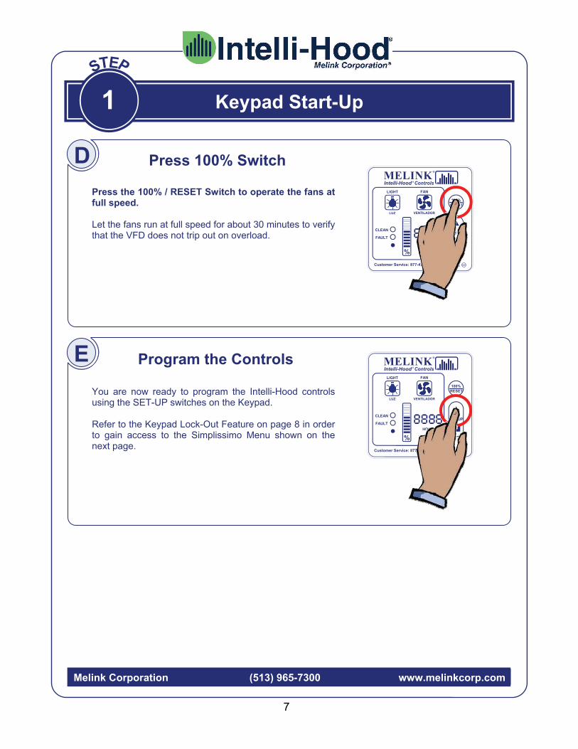
Press 100% Switch
Press the 100% / RESET Switch to operate the fans at full speed. Let the fans run at full speed for about 30 minutes to verify that the VFD does not trip out on overload.
You are now ready to program the Intelli-Hood controls using the SET-UP switches on the Keypad. Refer to the Keypad Lock-Out Feature on page 8 in order to gain access to the Simplissimo Menu shown on the next page.
Program the Controls E
Melink Corporation (513) 965-7300 www.melinkcorp.com
D
CLEAN
FAULT
HOOD
Customer Service: 877-477-4190 UL NSF
Listed 33x7
%
LUZ
LIGHT
VENTILADOR
FAN
100% RESET
Intelli-Hood Controls ® MELINK
®
SET-UP
CLEAN
FAULT
HOOD
Customer Service: 877-477-4190 UL NSF
Listed 33x7
%
LUZ
LIGHT
VENTILADOR
FAN
100% RESET
Intelli-Hood Controls ® MELINK
®
SET-UP
8
Programming
1
Melink Corporation (513) 965-7300 www.melinkcorp.com
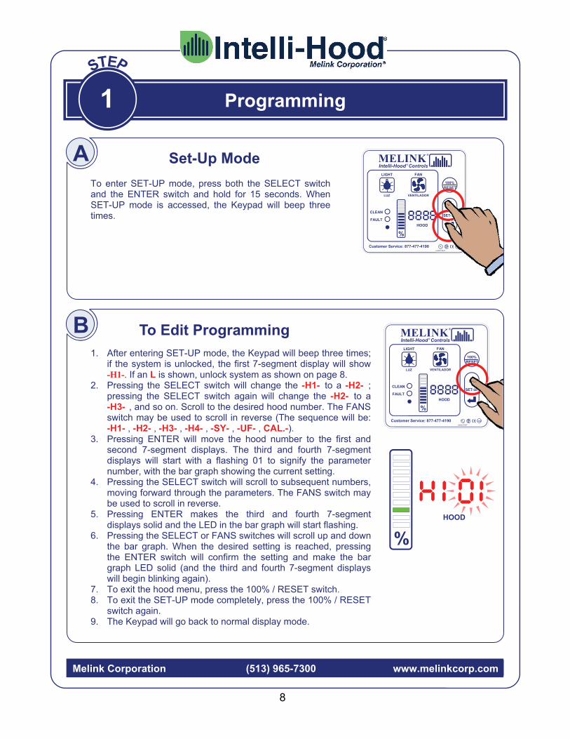
1. After entering SET-UP mode, the Keypad will beep three times; if the system is unlocked, the first 7-segment display will show -H1-. If an L is shown, unlock system as shown on page 8.
2. Pressing the SELECT switch will change the -H1- to a -H2- ; pressing the SELECT switch again will change the -H2- to a -H3- , and so on. Scroll to the desired hood number. The FANS switch may be used to scroll in reverse (The sequence will be: -H1- , -H2- , -H3- , -H4- , -SY- , -UF- , CAL.-).
3. Pressing ENTER will move the hood number to the first and second 7-segment displays. The third and fourth 7-segment displays will start with a flashing 01 to signify the parameter number, with the bar graph showing the current setting.
4. Pressing the SELECT switch will scroll to subsequent numbers, moving forward through the parameters. The FANS switch may be used to scroll in reverse.
5. Pressing ENTER makes the third and fourth 7-segment displays solid and the LED in the bar graph will start flashing.
6. Pressing the SELECT or FANS switches will scroll up and down the bar graph. When the desired setting is reached, pressing the ENTER switch will confirm the setting and make the bar graph LED solid (and the third and fourth 7-segment displays will begin blinking again).
7. To exit the hood menu, press the 100% / RESET switch. 8. To exit the SET-UP mode completely, press the 100% / RESET
switch again. 9. The Keypad will go back to normal display mode.
To enter SET-UP mode, press both the SELECT switch and the ENTER switch and hold for 15 seconds. When SET-UP mode is accessed, the Keypad will beep three times.
To Edit Programming
A Set-Up Mode
B
0
HOOD
%
CLEAN
FAULT
HOOD
Customer Service: 877-477-4190 UL NSF
Listed 33x7
%
LUZ
LIGHT
VENTILADOR
FAN
100% RESET
Intelli-Hood Controls ® MELINK
®
SET-UP
CLEAN
FAULT
HOOD
Customer Service: 877-477-4190 UL NSF
Listed 33x7
%
LUZ
LIGHT
VENTILADOR
FAN
100% RESET
Intelli-Hood Controls ® MELINK
®
SET-UP
9
Programming
1
Melink Corporation (513) 965-7300 www.melinkcorp.com
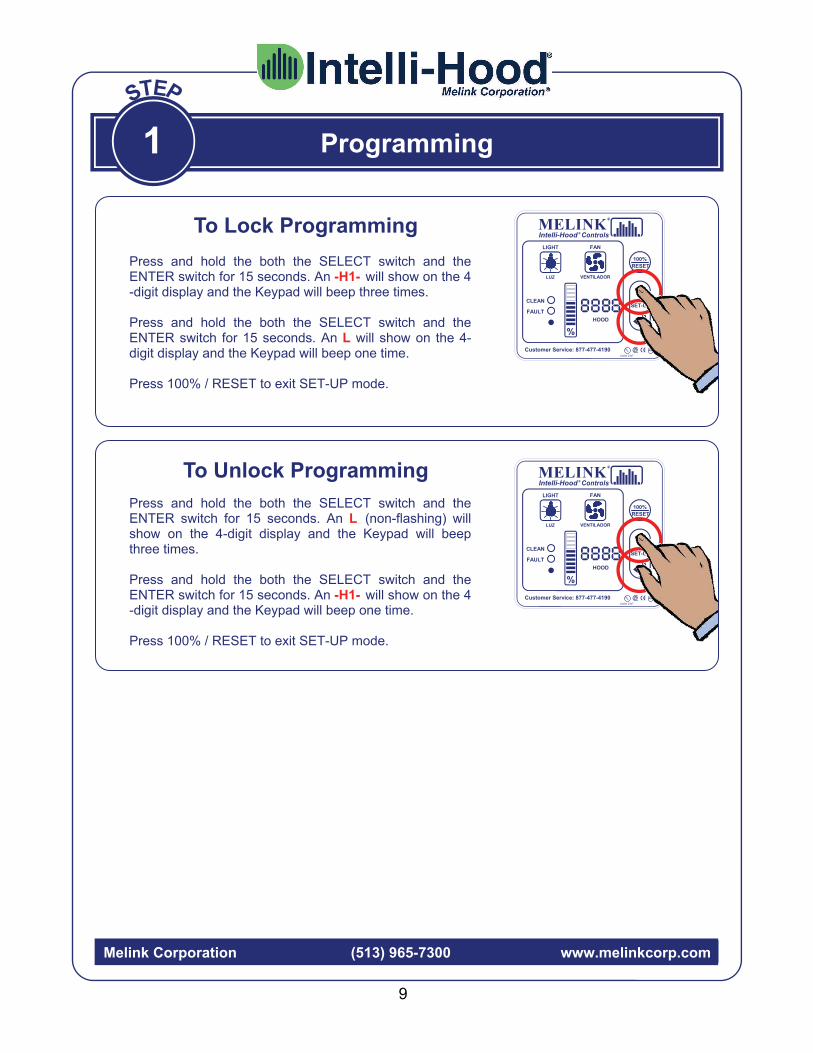
Press and hold the both the SELECT switch and the ENTER switch for 15 seconds. An L (non-flashing) will show on the 4-digit display and the Keypad will beep three times. Press and hold the both the SELECT switch and the ENTER switch for 15 seconds. An -H1- will show on the 4-digit display and the Keypad will beep one time. Press 100% / RESET to exit SET-UP mode.
To Lock Programming
Press and hold the both the SELECT switch and the ENTER switch for 15 seconds. An -H1- will show on the 4-digit display and the Keypad will beep three times. Press and hold the both the SELECT switch and the ENTER switch for 15 seconds. An L will show on the 4-digit display and the Keypad will beep one time. Press 100% / RESET to exit SET-UP mode.
To Unlock Programming

Fu
ture
Op
tio
ns
M
ore
op
tion
s cu
rre
ntly
u
nde
r d
eve
lopm
ent.
BA
S I
np
ut
Re
mo
te in
pu
ts f
rom
BA
S
en
able
the
co
ntr
ols
or
tell
th
e s
yste
m t
o tu
rn o
n o
r of
f.
Fu
ture
Op
tio
ns
M
ore
op
tion
s cu
rre
ntly
u
nde
r d
eve
lopm
ent.
Op
tic
Sen
sors
U
tiliz
ing
the
op
tic s
en
sors
allo
ws
the
sy
ste
m t
o o
pera
te m
ore
eff
icie
ntly
by
wa
tch
ing
for
any
tra
ces
of e
fflu
ent.
Imp
rove
d F
ire
Saf
ety
T
he c
ontr
ols
can
impr
ove
fire
saf
ety
by
mo
nito
ring
exh
au
st te
mp
era
ture
and
a
ctiv
atin
g th
e fa
ns,
so
und
ing
an
ala
rm,
an
d/o
r sh
ut d
ow
n f
ue
l to
app
lian
ces.
Inte
lli-H
oo
d F
eatu
res
& O
pti
on
s
Sta
nd
ard
Fe
atu
res
&
Ben
efi
ts
O
n/O
ff O
pti
on
s
T
emp
erat
ure
C
on
tro
l O
pti
on
s
O
pti
cs C
on
tro
l
Op
tio
ns
A
ux
iliar
y In
pu
t
Op
tio
ns
A
ux
iliar
y O
utp
ut
Op
tio
ns
A
dd
itio
nal
O
pti
on
s
Imp
rove
d E
ner
gy
Eff
icie
nc
y T
he c
ontr
ols
imp
rove
en
erg
y e
ffic
ien
cy
by
red
uci
ng
the
exh
aus
t a
nd m
ake
-up
fa
n s
pe
eds
durin
g id
le p
erio
ds.
Imp
rove
d K
itch
en C
om
fort
T
he c
ontr
ols
can
imp
rove
kitc
he
n
com
fort
by
red
uci
ng
the
su
pply
of
hot
/h
um
id M
UA
an
d r
edu
ce h
ood
no
ise.
Imp
rove
d O
ccu
pa
nt
Hea
lth
T
he c
ontr
ols
can
imp
rove
IA
Q b
y m
on
itorin
g C
O2
leve
ls a
nd
incr
ea
sin
g e
xha
ust
& s
upp
ly s
pe
eds
if ne
cess
ary
.
Imp
rove
d H
VA
C L
ife
T
he c
ontr
ols
ext
end
HV
AC
life
by
red
uci
ng
run
tie
an
d th
us
we
ar
an
d te
ar
on
equ
ipm
ent,
as
we
ll a
s p
rovi
din
g so
ft-
sta
rts
for
the
exh
au
st a
nd
sup
ply
fa
ns.
Man
ual
On
/Off
O
n/O
ff v
ia k
eyp
ad
fan
bu
tton
; if
act
ive
this
will
alw
ays
ove
rrid
e
an
y o
the
r o
n/o
ff m
eth
od.
Au
to O
n/O
ff
On
/Off
via
te
mp
era
ture
se
nso
rs;
On
tem
pe
ratu
re m
ay
be p
rogr
am
med
.
Re
mo
te E
nab
le
Pro
gra
mm
ab
le s
ett
ing
th
at r
equ
ires
exte
rnal
inte
rlock
to
allo
w f
an
s to
sta
rt.
Re
mo
te O
n/O
ff
On
/Off
via
th
e d
ry in
put
te
rmin
als
o
n th
e I/
O b
oa
rd.
Sch
edu
ling
O
n/O
ff v
ia s
che
dule
d ti
me
s;
ma
y b
e p
rogr
am
me
d fo
r
spe
cific
da
ys o
f th
e w
ee
k.
Co
mfo
rt M
od
e S
pa
ce a
nd s
upp
ly a
ir se
nso
rs c
an
de
term
ine
if fr
ee
coo
ling
ma
y b
e
util
ize
d a
nd
will
ove
rrid
e th
e
tem
pe
ratu
re s
pan
to in
cre
ase
fan
sp
eed
an
d a
ct a
s a
n ec
on
omiz
er.
Man
ual
Te
mp
Sp
an
T
empe
ratu
re s
pan
is m
anu
ally
se
t th
rou
gh th
e p
rogr
am
ma
ble
men
u.
Au
to T
emp
Sp
an
Au
to te
mp
sp
an w
ill a
dju
st to
util
ize
th
e e
ntir
e te
mp
era
ture
sp
an
a
nd
op
timiz
e e
ne
rgy
savi
ngs
.
Fir
e S
afet
y If
pro
gra
mm
ed, f
an
s w
ill a
ctiv
ate
in
case
of
a te
mpe
ratu
re a
larm
to p
oss
ibly
a
vert
a f
ire c
ond
ition
.
Fu
ture
Op
tio
ns
M
ore
op
tion
s cu
rre
ntly
u
nde
r d
eve
lopm
ent.
HV
AC
In
pu
t R
em
ote
inp
uts
fro
m R
TU
s, M
UA
, etc
. will
tell
the
sys
tem
e
ithe
r he
atin
g o
r co
olin
g is
ta
kin
g p
lace
, and
alg
orit
hm
s te
mp
ora
rily
ad
just
the
eff
ect
ive
tem
pe
ratu
re s
pa
n to
he
lp
ma
xim
ize
th
e e
ffe
ctiv
en
ess
of
the
pro
cess
.
IAQ
Sen
sors
R
em
ote
inp
uts
fro
m h
umid
ity,
C
O,
CO
2 se
nsor
s or
BA
S s
yste
m
tha
t ma
y a
dju
st fa
n s
pee
d.
Ap
pli
ance
Inp
ut
Arr
an
ge f
or
auto
mat
ic fa
n s
peed
ad
just
me
nt
ba
sed
on
sta
te o
f co
oki
ng
equ
ipm
ent.
Sys
tem
Rel
ay
Pro
gra
mm
ab
le F
orm
-C r
ela
y w
ith
cap
aci
ty o
f 1
5A
@ 2
30V
AC
Sys
tem
24V
AC
Ou
tpu
t 2
4V
AC
pro
gra
mm
able
ou
tpu
t ba
sed
in
syst
em
me
nu.
Ca
n b
e u
sed
for
ala
rm
ou
tpu
t, fa
n/e
quip
me
nt in
terlo
ck, e
tc.
Ho
od
24V
AC
Ou
tpu
t 2
4V
AC
pro
gra
mm
able
ou
tpu
t fo
r e
ach
h
ood
. C
an b
e u
sed
for
ala
rm o
utp
ut,
fan
/equ
ipm
en
t in
terlo
ck,
etc
.
Rem
ote
Ac
cess
A
na
log
or
wire
less
fe
atu
re t
hat a
llow
s th
e c
on
tro
ls s
yste
m t
o b
e r
emo
tely
m
on
itore
d a
nd s
erv
ice
d.
Inte
gra
l Dat
alo
gg
er
Sys
tem
ha
s on
-bo
ard
logg
er
th
at
will
tra
ck f
an
ope
ratio
n
for
up
to th
ree
we
eks
.
Sh
un
t-T
rip
Sh
utd
ow
n
Ab
ility
to r
am
p E
Fs
to fu
ll sp
eed
an
d
shut
dow
n s
upp
ly f
ans
with
sim
ple
ju
mpe
r se
ttin
g d
urin
g st
art
up.
ME
LIN
K
Inte
lli-H
oo
d
Co
ntr
ols
®
®
Mel
ink
Co
rpo
rati
on
(513
) 96
5-73
00
w
ww
.mel
inkc
orp
.co
m
10

Programming: Simplissimo
1
Melink Corporation (513) 965-7300 www.melinkcorp.com
01 02 03 04 05 06 07 08 09 10
Bar Graph
Exhaust Temp Span
Min. Fan Speed
Max. Fan Speed
Exhaust Temp. Alarm
Hood 24VAC Output
No. Hood Sensors
Auto On/Off
VFD Address
Add. VFD Address
Short-Cycle Ratio
10 70-85F Auto 100% FLASH AUD250F 24/7 No Sensors
9 70-80F 90% 95% FLASH AUD200F Fault 1O See
Scheduling in System
Menu
No Add. VFD
8 Auto TempSpan 80% 90% FLASH
AUD150F Mom Rel 4T/1O 15&16 80%
7 75-150 70% 85% FLASH AUD125F MUA Cool 3T/1O 13&14 70%
6 75-140 60% 80% FLASH AUD100F MUA Heat 2T/1O Heat-20% 11&12 60%
5 75-130 50% 75% FLASH 250F
MUA Damper 1T/1O Heat-15% No VFD 9&10 50%
4 75-120 40% 70% FLASH 200F Fans On 4T Heat-10% 4 8 40%
3 75-110 30% 65% FLASH 150F Smoke 3T Heat-5% 3 7 30%
2 75-100 20% 60% FLASH 125F
Exhaust Temp 2T Heat-0% 2 6 20%
1 75-90 10% 55% FLASH 100F No 1T No 1 5 No
11 12 13 14 15 16 17 18 19
Bar Graph
Hood Relay
Input (Dry)
Relay Inputs
to Utilize
Optic Sensor
Address* Scheduling Temp
Span Min Auto. On/Off Temp.
CFM Ratio for MUA/
AUX Output
Cable Length
VFD Software
10 T-Stat & 90% 110F/33F None
9 T-Stat & 80% 90F/33F 9
8 T-Stat & 75% None Sched.
1, 2, 3 80F/33F 8
7 T-Stat & 70% System 1, 2 Sched. 1, 3 100F/85F 7 PLC
6 T-Stat & 60%
Hood & System 2 Sched. 2, 3 100F/75F 6 AC Tech
5 T-Stat & 50%
Hood & System 1 Sched. 1, 2 85F 95F/75F 5 A-B PF400
4 100% on Closure System 2 Hood 4 Sched. 3
Only 80F 90F/75F 4 Yakasawa
3 Rem Enable System 1 Hood 3 Sched. 2
Only 75F 90F/70F 3 ABB
2 Rem On/Off
Hood & System 1,2 Hood 2 Sched. 1
Only 70F 85F/70F 2 IMO PC
1 No Hood Only Hood 1 No 65F 75F/65F 1 A-B PF4-40
Enter cable length
Basic Settings
Advanced Settings
(Defaults in Red)
HOOD MENU
11
FIRMWARE V2. 14

SY 01 SY 02 SY 03 SY 04 SY 05 SY 06 SY 07 SY 08 SY 09 SY 10
Bar Graph
4-20mA/ 0-10vdc Aux Out
4-20mA Aux In
Optics Hang Time
System Relay Input
1 (Dry)
System Relay Input
2 (Dry)
Bypass Timer
Comfort Mode
Sensors Misc.
System 24VAC Output
Optics Align-ment Check
10 T-Stat&90% T-Stat &90% 4 Hrs 24/7
9 Ext In T-Stat&80% T-Stat &80% 3 Hrs Fault
8 Hood Channel 4 Aux High T-Stat&75% T-Stat &75% 2 Hrs ConvCool/
WinSB/IB Mom Rel
7 Hood Channel 3 Aux Avg 180 Sec T-Stat&70% T-Stat &70% 1 Hr Conv Cool/
Int Bar MUA Cool
6 Hood Channel 2 Aux Sub 90 Sec T-Stat&60% T-Stat &60% 45 Min Win SB/Int
Bar MUA Heat
5 Hood Channel 1 Aux Add 60 Sec T-Stat&50% T-Stat &50% 30 Min Conv Cool
Only MUA
Damper Exit
4 Lowest Average 25 Sec 100% on Closure
100% on Closure 15 Min Econo +
Auto Win SB Only Fans On Hood 4
3 Highest Subtract 15 Sec Rem Enable Rem Enable 10 Min Auto Span Int Bar Smoke Hood 3
2 Average Add 10 Sec Rem On/Off Rem On/Off 5 Min Economizer Conv Cool/Win SB
Exhaust Temp Hood 2
1 No No 5 Sec No No No No No No Hood 1
SY 11 SY 12 SY 13 SY 14 SY 15 SY 16 SY 17 SY 18 SY 19 SY 20
Bar Graph
NO/NC Relay 15A @230VAC
Time Set
Schedule 1 Active Days
Schedule 1 Start
Schedule 1 Duration
Time
Schedule 1 Options
Schedule 2 Active Days
Schedule 2 Start
Schedule 2 Duration
Time
Schedule 2 Options
10 24/7
Enter time/date
C1: Hour C2: Minute C3: Day C4: Month C5: Day C6: Year C7: DST
Enter time of day
Hour Only
24 Hour Clock
5 hrs 5 hrs
9 Fault 4.5 hrs 4.5 hrs
8 Mom Rel Sun-Thurs 4 hrs Sun-Thurs 4 hrs
7 MUA Cool Sat-Sun 3.5 hrs Sat-Sun 3.5 hrs
6 MUA Heat Fri-Sun 3 hrs Fri-Sun 3 hrs
5 MUA Damper Fri-Sat 2.5 hrs Fri-Sat 2.5 hrs
4 Fans On Mon-Thurs 2 hrs On/Off Sched Mon-Thurs 2 hrs On/Off Sched
3 Smoke Mon-Fri 1.5 hr 100% Sched Mon-Fri 1.5 hr 100% Sched
2 Exhaust Temp All 1 hr 100% If On All 1 hr 100% If On
1 No None 0.5 hr Not Used None 0.5 hr Not Used
Enter time of day
Hour Only
24 Hour Clock
12
Programming: Simplissimo
1
Melink Corporation (513) 965-7300 www.melinkcorp.com
(Defaults in Red)
SYSTEM MENU
Continued
FIRMWARE V2. 14

SY 21 SY 22 SY 23 SY 24 SY 25 SY 26 SY 27 SY 28 SY 29 SY 30 SY 31
Bar Graph
Schedule 3 Active
Days
Schedule 3 Start
Schedule 3 Duration
Time
Schedule 3 Options
Keypad Function Disable
Cmft. Mode Space Temp
Cmft. Mode Supply Temp
MUA Heat If Kitchen <
MUA Heat If Supply <
MUA Cool If Kitchen >
Add. MUA Address
10
Enter time of day
Hour Only
24 Hour Clock
20 hrs 77 74F 80F
9 18 hrs 76 73F 65F 79F
8 16 hrs Byp+Lights 75 72 72F 63F 78F
7 14 hrs Fans+Byp 74 71 71F 60F 77F
6 12 hrs Fans+ Lights 73 70 70F 58F 76F 29,30,31
5 10 hrs Bypass 72 69 69F 55F 75F 30,31
4 8 hrs On/Off Sched Lights 71 68 68F 53F 74F 29
3 6 hrs 100% Sched Fans 70 67 67F 50F 73F 30
2 4 hrs 100% If On All 69 66 66F 48F 72F 31
1 2 hrs Not Used No 68 Tk>To 65F 45F 71F No
SY 32 SY 33 SY 34 SY 35 SY 36 SY 37 SY 38 SY 39 SY 40 SY 41 SY 42
Bar Graph
AUX VFD Software
Gain for AUX Input
Modem Options
Data Log Sample
Rate
US / SI Units
Selection
Day On/ Day Off
Monitoring
Smoke Density
Fire Safety
Full Speed @ Start
Supply Temp Cable Length
Space Temp Cable Length
10 150%
9 140%
8 130%
7 PLC 120% 5 min
6 AC Tech 110% 3 min 5 Min.
5 A-B PF400 100% 2 min 4 Min. enter cable length
enter cable length
4 Yakasawa 90% Wireless 1 min 24H Degrees C Proportional 3 Min.
3 ABB 80% 9+Auto-Dial 30 sec 12H Degrees C Heavy All Hoods 2 Min.
2 IMO PC 70% Auto-Dial 10 sec 24H Degrees F Active Medium Alarm Hood
Only 1 Min.
1 A-B PF4-40 60% No No 12H
Degrees F Disabled Light No No
13
Programming: Simplissimo
1
Melink Corporation (513) 965-7300 www.melinkcorp.com
(Defaults in Red)
SYSTEM MENU
FIRMWARE V2. 14
Sun-Thurs
Sat-Sun
Fri-Sun
Fri-Sat
Mon-Thurs
Mon-Fri
All
None
Continued
14
Programming: Simplissimo
1
Melink Corporation (513) 965-7300 www.melinkcorp.com
(Defaults in Red)
SYSTEM MENU
FIRMWARE V2. 14
Bar Graph
10
9
8
7
6
5
4
3
2
1
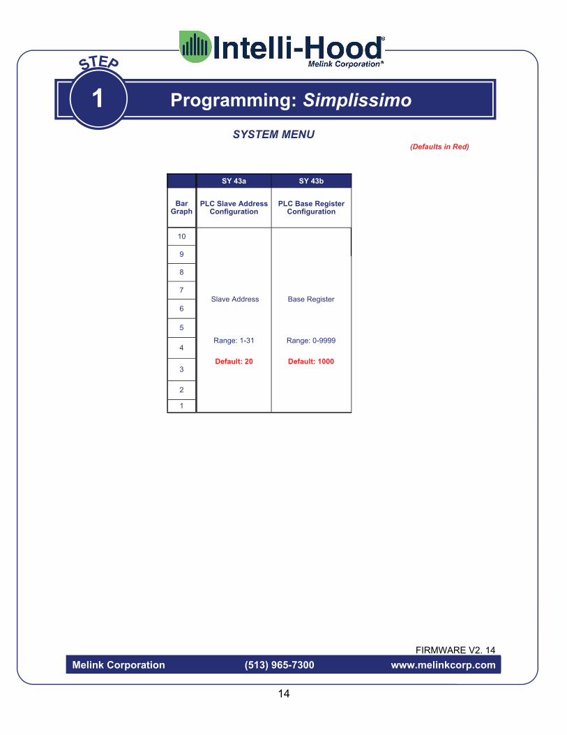
SY 43a SY 43b
Slave Address
Range: 1-31
Default: 20
Base Register
Range: 0-9999
Default: 1000
PLC Slave Address Configuration
PLC Base Register Configuration

CLEAN
FAULT
HOOD
Customer Service: 877-477-4190 UL NSF
Listed 33x7
%
LUZ
LIGHT
VENTILADOR
FAN
100% RESET
Intelli-Hood Controls ® MELINK
®
SET-UP
CLEAN
FAULT
HOOD
Customer Service: 877-477-4190 UL NSF
Listed 33x7
%
LUZ
LIGHT
VENTILADOR
FAN
100% RESET
Intelli-Hood Controls ® MELINK
®
SET-UP
CLEAN
FAULT
HOOD
Customer Service: 877-477-4190 UL NSF
Listed 33x7
%
LUZ
LIGHT
VENTILADOR
FAN
100% RESET
Intelli-Hood Controls ® MELINK
®
SET-UP
The fans can be operated at full speed like a conventional hood system by pressing the 100% / RESET button. This should only be used if there is noticeable smoke loss and the fans are not already running at full speed. Upon pressing this button, the bar graph will flash 100% speed and the letter “E” will be displayed with each hood desig-nation. After the preset period of time, the fan speed will return to its previous operation mode.
Press 100% Switch In Case of Emergency
Melink Corporation (513) 965-7300 www.melinkcorp.com
The hood fans turn on. Fan speed automatically varies with the heat/smoke load generated by the cooking appliances. This reduces hood noise, improves kitchen comfort, and saves energy. The bar graph on the Keypad indicates the fan speed for each hood. If the CLEAN light flashes red and green, clean the lenses on the Optic Sensors.
Sequence of Operation
Press Fan Switch B
C
Press Light Switch
The hood lights turn on.
A
2
15
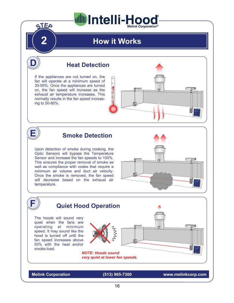
If the appliances are not turned on, the fan will operate at a minimum speed of 30-50%. Once the appliances are turned on, the fan speed will increase as the exhaust air temperature increases. This normally results in the fan speed increas-ing to 50-80%.
Melink Corporation (513) 965-7300 www.melinkcorp.com
Upon detection of smoke during cooking, the Optic Sensors will bypass the Temperature Sensor and increase the fan speeds to 100%. This ensures the proper removal of smoke as well as compliance with codes that require a minimum air volume and duct air velocity. Once the smoke is removed, the fan speed will decrease based on the exhaust air temperature.
The hoods will sound very quiet when the fans are operating at minimum speed. It may sound like the hood is turned off until the fan speed increases above 50% with the heat and/or smoke load. NOTE: Hoods sound
very quiet at lower fan speeds.
Quiet Hood Operation
Smoke Detection E
F
Heat Detection D
How it Works
2
16

Melink Corporation (513) 965-7300 www.melinkcorp.com
View Time
Time = 12:25
To view the time, press the Enter key. The digital display will first show the hour and then the time of day and date. It will show this only once, then it will return to the previous display.
Time Time of day = afternoon (pm)
Day = Wednesday (4th day of week)
I
17
How it Works
During normal operation, the Key-pad bar graph will indicate the per-cent fan speed of each hood. The digital display will continually scroll through each hood connected to the system every 5 seconds.
%
Exhaust Rate Scrolling
Hood 1: Exhaust rate is 40%
%
%
2
View Current Hood Exhaust Rates
G
View Current Temps, Average Exhaust Fan & Current Supply Fan Speed
H
Temp. & VFD Scroll-
%
Hood 1: Temp. = 115º ; VFD Speed = 40%
%
Hood 2: Temp. = 125º ; VFD Speed = 60%
To view the temperatures and average VFD speeds for each hood, press the selection switch one time. The exhaust temperature will be shown in the digital display, and the VFD speeds will be shown in the bar graph. It will scroll through only once, then return to showing the percent fan speeds.
Hood 2: Exhaust rate is 60%
Hood 3: Exhaust rate is 50%
%
Hood 4: Exhaust rate is 30%
%
Auxiliary Output
Space Temp
%
Supply Temp
%
Temp. = 73º Output = 60%
Temp. = 77º

Optic Sensors
Clean the temperature sensors at least once a year or as needed by simply wiping off any grease with a clean cloth. This will ensure the sensors respond quickly to any change in exhaust air temperature.
End of hood
Melink Corporation (513) 965-7300 www.melinkcorp.com
If the “Clean” indicator light on the Keypad begins to flash from red to green, the optic lenses need cleaning. First, wipe off the lenses on each end of the hood with a clean, soft cloth. Press the fan switch off and then on again to initiate automatic calibration of the Optic Sensors now that they have clean lenses. The indicator light should turn green within about five seconds to confirm calibration. IMPORTANT: Advise your hood/duct cleaner not to spray hot water or steam into the photo housings so that the Receiver and Emitter do not get wet. The photo housings should be covered to ensure protection of these devices.
Exhaust Duct
Maintenance
3
B
A
Temperatures Sensors
18
Water Agua
Problem:
1
2
3
4
5
6
8
7
9
%
CLEAN
FAULT
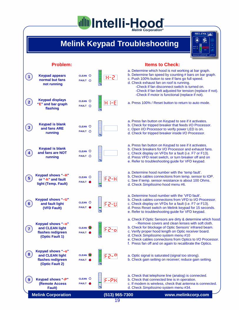
a. Determine which hood is not working at bar graph. b. Determine fan speed by counting # bars on bar graph. c. Push 100% button to see if fans go full speed. d. Check exhaust fan on roof is running. -Check if fan disconnect switch is turned on. -Check if fan belt adjusted for tension (replace if not). -Check if motor is functional (replace if not). a. Press 100% / Reset button to return to auto mode. a. Press fan button on Keypad to see if it activates. b. Check for tripped breaker that feeds I/O Processor. c. Open I/O Processor to verify power LED is on. d. Check for tripped breaker inside I/O Processor. a. Press fan button on Keypad to see if it activates. b. Check breakers for I/O Processor and exhaust fans. c. Check display on VFDs for a fault (i.e. F7 or F13). d. Press VFD reset switch, or turn breaker off and on e. Refer to troubleshooting guide for VFD keypad. a. Determine hood number with the ‘temp fault’. b. Check cables connections from temp. sensor to IOP. c. See if temp. sensor resistance is about 100 Ohms. d. Check Simplissimo hood menu #6. a. Determine hood number with the ’VFD fault’. b. Check cables connections from VFD to I/O Processor. c. Check display on VFDs for a fault (i.e. F7 or F13). d. Press Reset switch on Melink keypad for 15 seconds. e. Refer to troubleshooting guide for VFD keypad.
a. Check if Optic Sensors are dirty & determine which hood. - Remove covers and clean lenses with soft cloth. b. Check for blockage of Optic Sensors’ infrared beam. c. Verify proper hood length on Optic receiver board. d. Check Simplissimo system menu #10 e. Check cables connections from Optics to I/O Processor. f. Press fan off and on again to recalibrate the Optics. a. Optic signal is saturated (signal too strong). b. Check gain setting on receiver; reduce gain setting. a. Check that telephone line (analog) is connected. b. Check that connected line is in operation. c. If modem is wireless, check that antenna is connected. d. Check Simplissimo system menu #34.
Items to Check:
%
CLEAN
FAULT
%
CLEAN
FAULT
%
CLEAN
FAULT
%
CLEAN
FAULT
CLEAN
%
FAULT
%
CLEAN
FAULT
%
CLEAN
FAULT
Keypad appears normal but fans
not running
Keypad displays “E” and bar graph
flashing
Keypad is blank and fans ARE
running
Keypad is blank and fans are NOT
running
Keypad shows “–H” or “-h” and fault
light (Temp. Fault)
Keypad shows “–U” and fault light
(VFD Fault)
Kepyad shows “–o” and CLEAN light flashes red/green
(Optic Fault 1)
Kepyad shows “–o” and CLEAN light flashes red/green
(Optic Fault 2)
Keypad shows “-P” (Remote Access
Fault)
CLEAN
%
FAULT
Melink Keypad Troubleshooting
19 Melink Corporation (513) 965-7300 www.melinkcorp.com

Problem:
1
2
3
4
5
6
8
7
a. Check AC power input to drive for low voltage or line power interruption.
a. Check AC power input to drive for high line voltage. Assure
deceleration time is set at 60 seconds. a. Output current to motor exceeds limit set by parameter P033.
Check motor and fan for conditions that may cause excessive motor current.
b. Check for appropriate Start Boost (A084). a. Check to see if cooling fan is running. If not, replace fan. b. Check for blocked or dirty heat sink fins. Verify that ambient
temperature is not above 104º F. a. The drive output current has exceeded the hardware current
limit. Check to see if the drive is sized properly for the motor. b. Check for appropriate Start Boost (A084). a. Check the motor and external wiring for a grounded condition. b. Other potential causes include switching a load-side
disconnect during operation and shorted wires. c. Attempt to re-start the drive by pressing the Reset switch on
the keypad for approximately 10 seconds.
a. Drive has automatically re-started from another fault for the
programmed number of times. Check the fault history (d008, d009) to determine the cause of the problem.
a. Drive rating of 150% for 1 minute or 200% for 3 seconds has
been exceeded. Reduce load or extend acceleration time. b. Attempt to re-start the drive by pressing the Reset switch on
the keypad for approximately 10 seconds.
Items to Check:
Under Voltage
Over Voltage
Motor Overload
Heatsink Over Temperature
Hardware Overcurrent
Ground Fault
Automatic Restart
Drive Overload
VFD Keypad Troubleshooting
Melink Corporation (513) 965-7300 www.melinkcorp.com
20

Warranty
4
21
No returns will be accepted without prior written approval from Melink Corporation. All returned shipments must be prepaid and are subject to handling charges.
Notify the carrier in the event of damaged shipments, whether they are apparent at the time of delivery or when unpacked. File a complaint with the carrier, as the customer is responsible for the collection of damage claims.
Melink Corporation (513) 965-7300 www.melinkcorp.com
Damaged Shipments
Returns
Warranty
To validate the warranty, complete and return the warranty validation form in the Owner’s Manual. Complete one form for each system installed and send to Melink Corporation at the following address within 10 days:
Melink Intelli-Hood® Attn: Warranty Validation 5140 River Valley Road
Milford, OH 45150 Melink Corporation extends this warranty to the original buyer and warrants that Melink products shall be free from original defects in workmanship and material for three years from date of shipment, provided same has been properly stored, installed, operated, maintained, and serviced. This warranty does not apply to products which have been altered or repaired without expressed written authorization from Melink Corporation, or altered or repaired in any way so as to affect its performance or its reliability, nor which have been subjected to misuse, negligence or accident. The buyer assumes responsibility for all risks and liabilities resulting from the use of these products. Melink Corporation is not responsible for the cost of removal of the defective product or part, damages due to removal, or any expenses incurred in shipping the product or part to or from the plant, or the installation of the repaired or replaced product or part.

22
Warranty
4
Melink Corporation (513) 965-7300 www.melinkcorp.com
Please complete this form and fax to Melink at (513) 527-7023, or send by mail to: Melink Corporation, 5140 River Valley Road, Milford, OH 45150.
Owner Date Company Address City State Zip Country Phone Fax Email MODEL (located inside I/O Processor) SERIAL NO. (located inside I/O Processor) Installer Address City State Zip Phone Date of Installation & Start-Up


Please let us know how we can improve our Operations Manual. We want your experience with our product to exceed all expectations.
Call Melink Customer Service at 513-965-7300 if you have any questions.