operations of the geometric and military...
TRANSCRIPT

OPERATIONS OF THE GEOMETRIC AND MILITARY COMPASS
OF
GALILEO GALILEI
FLORENTINE PATRICIAN AND TEACHER OF MATHEMATICS
in the University of Padua
Dedicated to
THE MOST SERENE PRINCE DON COSIMO DE’ MEDICI.
PRINTED AT PADUA
in the Author’s House, By Pietro Marinelli. 1606 With license of the Superiors
Translated by Stillman Drake, Florence 1977
CONTENTS Dedication............................................................................................................................ 5 Prologue .............................................................................................................................. 6 Operation I Division of a line .................................................................................................................. 7 Operation II How in any given line we can take as many parts as may be required .............................. 8 Operation III How these same lines give us two, and even infinitely many, scales for altering one map into another larger or smaller ............................................................................... 8 Operation IV The rule-of-three solved by means of a compass and these same Arithmetic Lines .................................................................................................................................... 9 Operation V The inverse rule-of-three resolved by means of the same lines ......................................... 10 Operation VI Rule for monetary exchange ............................................................................................... 10 Operation VII Rule for compound interest, also called “New Year’s gain” ................................................ 11 Operation VIII Of the Geometric Lines which follow next, and the uses thereof. And first how by means of these we can increase or decrease in any ratio all areas of figures .............. 12 Operation IX How with the same lines we can find the ratio of two similar plane figures ........................ 12 Operation X How you can construct a plane figure similar and equal to several others given ............... 13 Operation XI Given two unequal similar figures, to find a third, similar to these and equal to their difference..................................................................................................................... 13 Operation XII Square root extraction with the help of these same lines ................................................... 14 Operation XIII Rule for arranging armies with unequal front and flanks..................................................... 15 Operation XIV Discovery of the mean proportional by means of these same lines.................................... 16 Operation XV Of the Stereometric Lines, and first, how by means of these all similar solids can be increased or diminished in any given ratio .............................................................. 17 Operation XVI Given two similar solids, to find the ratio between them ..................................................... 17
2
Operation XVII Given any number of similar solids, to find a single one equal to all of them together ............................................................................................................................... 17 Operation XVIII Extraction of cube root ........................................................................................................ 18 Operation XIX Discovery of two mean proportionals .................................................................................. 19 Operation XX How every parallelopiped can be re-duced to a Cube by means of the Stereometric Lines .............................................................................................................. 19 Operation XXI Explanation of the Metallic Lines, marked next to the Stereometric ................................... 20 Operation XXII How with the aforesaid lines we can find the ratio of weight between all metals and other materials marked along the Metallic Lines.......................................................... 20 Operation XXIII Combining the uses of the Metallic and the Stereometric lines, and given two sides for two similar solids made of different materials, to find the ratio of their weights ................................................................................................................................ 21 Operation XXIV How these lines serve universally for the gunners’ calibration for all cannonballs of any material and of every weight ................................................................ 21 Operation XXV How, given a body of any material, we can find all the particular measures of one of different material that shall weigh a given amount................................................... 22 Operation XXVI Of the Polygraphic Lines, and how by these we can describe regular polygons, that is, figures of many equal sides and angles .................................................................. 24 Operation XXVII Division of a circle into as many parts as is desired............................................................ 24 Operation XXVIII Explanation of the Tetragonic Lines, and how by their means one may square the circle, or any other regular figure, and may also transform all these, one into another.......................................................................................................................... 25 Operation XXIX Given different regular figures, how-ever dissimilar to one another, how to construct a single one equal to all of them together ........................................................... 25 Operation XXX How one may make any desired regular figure that equals any given irregular (but rectilinear) figure .......................................................................................................... 25 Operation XXXI Lemma for [currying out] the things said above .................................................................. 26 Operation XXXII Of the Added Lines for the quadrature of segments of a circle and of figures containing parts of circumferences, or straight and curved lines together.......................... 27
3
Of the operations of the quadrant ....................................................................................... 29 Various ways of measurement by sighting; and first, of vertical heights whose bases we can approach, and [from which we can] retire .................................................... 30
4
TO THE MOST SERENE DON COSIMO DE’ MEDICI
PRINCE OF TUSCANY, ETC.
If, Most Serene Prince, I wished to set forth in this place all the praises due to your Highness’ own merits and those of your distinguished family, I should be committed to such a lengthy discourse that this preface would far outrun the rest of the text, whence I shall refrain from even attempting that task, uncertain that I could finish half of it, let alone all. Besides, it was not to magnify your splendor (which already shines like a rising sun on all the West) that I took occasion to dedicate the present work to you, but rather that this should always carry the embellishment and ornamentation of your name written in front of it, as in my mind, bringing grace and splendor to its dark shadows. Nor do I step forth as an orator to exalt your Highness’ glory, but as your most devoted servitor and humble subject I offer you due tribute as I should have done before, had not your tender age persuaded me to await these years more suited to such studies. I doubt not that this little gift will be gladly received by you, not only because your infinite native gentility so persuades me, but because I am sure this reading is proportioned to your many other regal exercises, besides which experience itself confirms me in this, you having deigned during most of last summer to listen benignly to my oral explanation of many uses of this Instrument. May your Highness therefore enjoy this, my mathematical game so to speak, nobly suited to your first youthful studies. And advancing with age in these truly royal disciplines, expect from my simple mind from time to time those more mature fruits that Divine Grace has conceded it to me to gather. And so, with all humility, I bow to kiss reverently your robe and pray God for your great happiness. From Padua, the 10th of July 1606. From your Highness’
Most Humble and Obliged Servant
Galileo Galilei.
5

TO THE DISCREET READERS
The opportunity of dealing with many great gentlemen in this most noble University of Padua, introducing them to the mathematical sciences, has by long experience taught me that not entirely improper was e request of that royal pupil who sought from Archimedes, as his teacher of geometry, an easier and more open road that would lead him to its possession; for even in our age very few can patiently travel the steep and thorny paths along which one first must pass before acquiring the precious fruits of this science, frightened by the long rough road, and not seeing or being able to imagine how those dark and unfamiliar paths can lead them to the desired goal, they falter halfway there and abandon the undertaking. I have seen this happen the more frequently, the greater the personages I have deal, with, as men who being occupied and distracted by many other affairs cannot exercise in this that assiduous patience that would be required of them. Hence I excuse them together with that young King of Syracuse and desiring that they should not remain deprived of knowledge so necessary to noble gentlemen by reason of the length and difficulty of ordinary roads. I fell to tying to open this truly royal road-for with the aid of my Compass I do that in a few days, teaching everything derived from geometry and arithmetic for civil and military use that is ordinarily received only by very long studies. I shall not say what I have accomplished by this work of mine, but let those judge who have learned from me up to now, or will learn in the future, and especially those who have seen instruments invented by others for similar purposes-although most of the inventions, and the best that are included in my Instrument, have not previously been attempted (or imagined) by them. Among these, the foremost is that of enabling anyone to resolve instantly the most difficult arithmetical operations; of which, however, I shall describe only those that occur most frequently in civil and military affairs. I regret only, Gentle Readers that although I have taken pains to explain the ensuing things with all possible clarity and facility, yet to those who must draw them from writing even these will remain cloaked in some obscurity losing for many people that grace which arouses marvel in seeing them actually performed, and in learning them by word of mouth But these are maters that do not permit themselves to be described with ease and clarity unless one has first heard them orally and has seen them in the act of being carried out. This indeed would have been a powerful reason for me to refrain from printing this work, had it not come to my ears that another into whose hands my Instrument and its explanation, had come, I know not what form , was preparing to appropriate it to himself. This made it necessary to insure by printed evidence my labors and reputation against any who wanted to claim it By way of warning there are not lacking testimonies of princes and other great gentlemen who in the past eight years have seen this Instrument and learned from me its use, of whom it will suffice to name only four One was the illustrious and excellent John Frederick, Prince of Holsace and Count of Oldenburg, who in 1598 learned from me the use of the Instrument although it was then not yet brought to perfection. Soon afterward I was honored similarly by the most Serene Archduke Ferdinand of Austria. The illustrious and most excellent t Phillip Landgrave - of Hessia and Count of Nidda, studied the said use here at Padua in 1601, and two years ago the Most Serene Duke of Mantua requested its explanation from me It may be added that my silence about the construction of the Instrument, which I shall omit at present for its long and laborious description (and for other reasons) will render this treatise quite useless to anyone whose hands it reaches without the Instrument itself. That is why I have had but sixty copies printed, a, my house, to be presented together with an Instrument devised and made with that great care which is necessary, first to my Lord the Most Serene Prince of Tuscany, and then to other gentlemen by whom I know this work of mine to be desired. Finally, it being my intention to explain at present mainly those operations of interest to soldiers, I have judged it good to write in the Tuscan language so that the book, coming into the hands of persons better informed in military matters than in the Latin language, can be understood easily by them.
Live happily.
6
DIVISION OF A LINE
First Operation
Coming to the detailed explanation of the operations of this new Geometric and Military Compass, we shall begin first with the face on which there are marked four pairs of lines with their divisions and scales; among those we shall first speak of the innermost, called the Arithmetic Lines from their division in arithmetical progression; that is, by equal additions which proceed out to the number 250. We shall gather various uses for these Lines; and first:
By means of these Lines we can divide any given straight line into as many equal parts as desired, operating in any of the ways set forth below. When the given line is of medium size, so that it does not exceed the opening of the Instrument, we take its whole length with an ordinary compass and apply this distance crosswise, opening the Instrument, to some number [and its counterpart on the other arm] on these Arithmetic Lines such that above it, on these same Lines, there is a smaller number contained by the selected number as many times as there are parts into which the given line is to be divided. Then the crosswise distance taken between the bearing this smaller number will doubtless divide the given line info the required parts. For example:
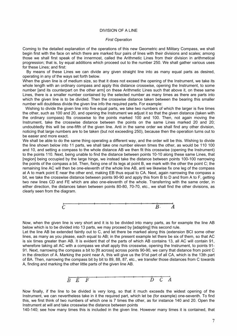
Wishing to divide the given line into five equal parts, we take two numbers of which the larger is five times the other, such as 100 and 20, and opening the Instrument we adjust it so that the given distance (taken with the ordinary compass) fits crosswise to the points marked 100 and 100. Then, not again moving the Instrument, take the crosswise distance between the points on the same Lines marked 20 and 20; undoubtedly this will be one-fifth of the given line. Anti in the same order we shall find any other division, noticing that large numbers are to be taken (but not exceeding 250), because then the operation turns out to be easier and more exact. We shall be able to do the same thing operating a different way, and the order will be this. Wishing to divide the line shown below into 11 parts, we shall take one number eleven times the other, as would be 110 100 and 10, and setting a compass to the whole distance AB we then fit this crosswise (opening the Instrument) to the points 110. Next, being unable to find the distance between points 10-10 along these same Lines, that [region] being occupied by the large hinge, we instead take the distance between points 100-100 narrowing the points of the compass a bit. Then, fixing one of its legs at point B, we mark with the other the point C; the remaining line AC will then be one-eleventh of the whole line AB, anti we likewise fix one leg of the compass at A to mark point E near the other end, making EB thus equal to CA. Next, again narrowing the compass a bit, we take the crosswise distance between points 90-90 and apply this from B to D and from A to F, getting two new lines CD and FE which are also one-eleventh of the whole. Transferring with the same order, in either direction, the distances taken between points 80-80, 70-70, etc., we shall find the other divisions, as clearly seen from the diagram.
Now, when the given line is very short and it is to be divided into many parts, as for example the line AB below which is to be divided into 13 parts, we may proceed by [adapting] this second rule. Let the line AB be extended faintly out to C, and let there be marked along this (extension BCI some other lines, as many as you please, each equal to AB; in the present example let there be six of them, so that AC is six times greater than AB. It is evident that of the parts of which AB contains 13, all AC will contain 91, wherefore taking all AC with a compass we shall apply this crosswise, opening the Instrument, to points 91-91. Next, narrowing the compass a bit to [fit across] across points 90-90, we carry that distance from point C in the direction of A. Marking the point near A, this will give us the 91st part of all CA, which is the 13th part of BA. Then, narrowing the compass bit by bit to 89, 88, 87, etc., we transfer those distances from C towards A, finding and marking the other little parts of the given line AB.
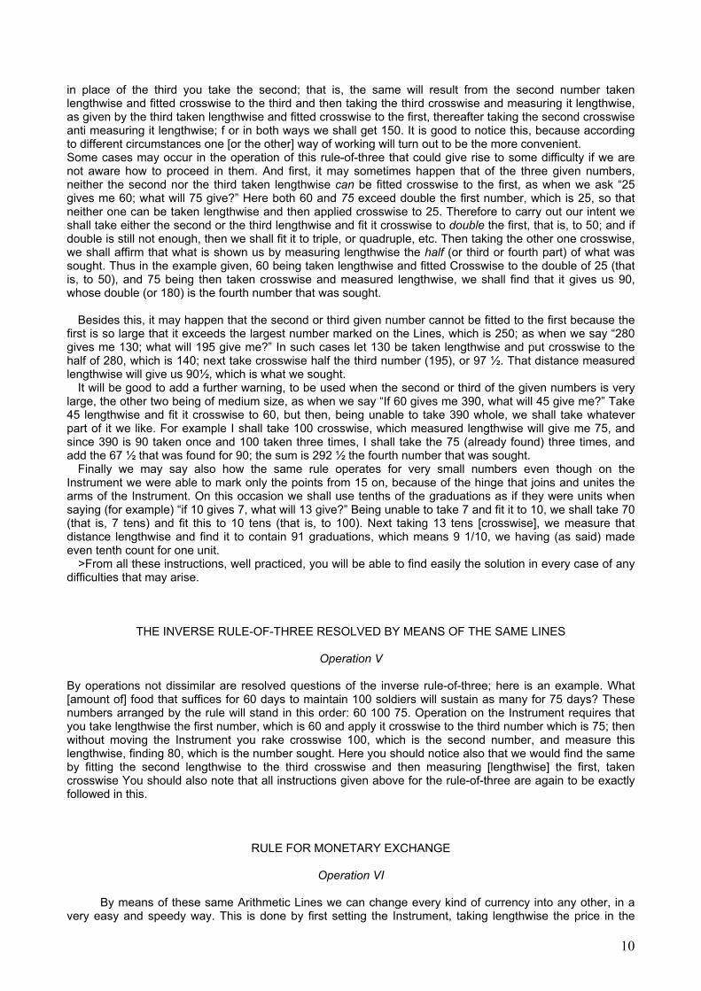
Now finally, if the line to be divided is very long, so that it much exceeds the widest opening of the Instrument, we can nevertheless take in it the required part, which let be (for example) one-seventh. To find this, we first think of two numbers of which one is 7 times the other, as for instance 140 and 20. Open the Instrument at will and take crosswise the distance between points 140-140; see how many times this is included in the given line. However many times it is contained, that
7

many times is the crosswise distance between points 20-20 to be repeated along the large line, and you will have its one-seventh part if the distance taken between points 140-140 precisely measured the given line. If it did not exactly measure this, it will be necessary to take one-seventh of the excess in the manner previously explained, and by adding that to the distance which was laid off many times along the large line, you will have its one-seventh part to a hair, just as was desired.
HOW IN ANY GIVEN LINE WE CAN TAKE AS MANY PARTS AS MAY BE REQUIRED
Operation II This operation is the more useful and necessary according as without the help of our Instrument it may be [the more] difficult to find such divisions, which can nevertheless he found instantly with the Instrument. Thus when one is asked to take in a given line some parts, such as (for example) 113 parts out of 197, one just takes the length of the line with a compass and opens the Instrument so that this length fits crosswise between the points marked 197-197; without again moving the Instrument, take with the same compass the distance between points 113-113, and that will doubtless be the fraction of the line requested, equal to one-hundred-thirteen one-hundred-ninety-sevenths of it.
HOW THESE SAME LINES GIVE US TWO, AND EVEN INFINITELY MANY, SCALES FOR ALTERING ONE MAP INTO ANOTHER
LARGER OR SMALLER
Operation III Is evident that whenever it is required to draw from a given diagram another similar one, large or smaller in any desired ratio, we must use two scales accurately divided, one of which serves to measure the drawing already made, and the other for marking the lines of the drawing to he made. Two such scales we shall always have from the Lines of which we are now speaking. One will be the line already divided lengthwise along the Instrument: this established scale will serve us for measuring the sides of the given drawn. The other, for drawing the new design, must be alterable; that is, it must be capable of increase or diminution at our pleasure, according as the new drawing is to be larger or smaller. This variable scale will be that which we have crosswise from the same Lines by narrowing or widening the opening of our Instrument. For a clearer understanding of the manner of putting these Lines to use, let us take an example.
Thus, let diagram ABCDE be given, which we are to draw another, similar, but based on line FG which is to be homologous (that is, corresponding) to line AB. Here it is evident that two scales must be used, one to measure the lines of diagram ABCDE and another by which will be measured the lines of the diagram to be drawn, and this latter must be greater or less than the other scale according to the ratio of line FG to line AB. Therefore take with a compass the length AB, putting one leg of the compass at the pivot of the Instrument and the other at any point it strikes, [establishing a measure for the line] which in our example let be point 60.
8
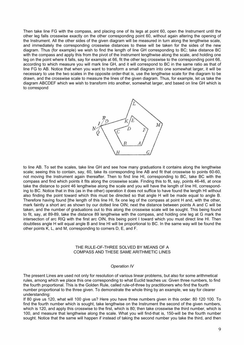
Then take line FG with the compass, and placing one of its legs at point 60, open the Instrument until the other leg falls crosswise exactly on the other corresponding point 60, without again altering the opening of the Instrument. All the other sides of the given diagram will be measured in turn along the lengthwise scale, and immediately the corresponding crosswise distances to these will be taken for the sides of the new diagram. Thus (for example) we wish to find the length of line GH corresponding to BC; take distance BC with the compass and apply this from the pivot of the Instrument lengthwise along the scale, and holding one leg on the point where it falls, say for example at 66, fit the other leg crosswise to the corresponding point 66, according to which measure you will mark line GH, and it will correspond to BC in the same ratio as that of line FG to AB. Notice that when you want to transform a small diagram into one somewhat larger, it will be necessary to use the two scales in the opposite order-that is, use the lengthwise scale for the diagram to be drawn, and the crosswise scale to measure the lines of the given diagram. Thus, for example, let us take the diagram ABCDEF which we wish to transform into another, somewhat larger, and based on line GH which is to correspond
to line AB. To set the scales, take line GH and see how many graduations it contains along the lengthwise scale; seeing this to contain, say, 60, take its corresponding line AB and fit that crosswise to points 60-60, not moving the Instrument again thereafter. Then to find line HI, corresponding to BC, take BC with the compass and find which points it fits along the crosswise scale. Finding this to fit, say, points 46-46, at once take the distance to point 46 lengthwise along the scale and you will have the length of line HI, correspond-ing to BC. Notice that in this (as in the other) operation it does not suffice to have found the length HI without also finding the point toward which this must be directed so that angle H will be made equal to angle B. Therefore having found [the length of this line HI, fix one leg of the compass at point H and, with the other, mark faintly a short arc as shown by our dotted line OIN; next the distance between points A and C will be taken, and the number of graduations out to this along the crosswise scale will be sought. This being found to fit, say, at 89-89, take the distance 89 lengthwise with the compass, and holding one leg at G mark the intersection of arc RIQ with the first arc OIN, this being point I toward which you must direct line HI. Then doubtless angle H will equal angle B and line HI will be proportional to BC. In the same way will be found the other points K, L, and M, corresponding to corners D, E, and F.
THE RULE-OF-THREE SOLVED BY MEANS OF A COMPASS AND THESE SAME ARITHMETIC LINES
Operation IV
The present Lines are used not only for resolution of various linear problems, but also for some arithmetical rules, among which we place this one corresponding to what Euclid teaches us: Given three numbers, to find the fourth proportional. This is the Golden Rule, called rule-of-three by practitioners who find the fourth number proportional to the three given. To demonstrate the whole thing by an example, we say for clearer understanding: If 80 give us 120, what will 100 give us? Here you have three numbers given in this order: 80 120 100. To find the fourth number which is sought, take lengthwise on the Instrument the second of the given numbers, which is 120, and apply this crosswise to the first, which is 80; then take crosswise the third number, which is 100, and measure that lengthwise along the scale. What you will find-that is, 150-will be the fourth number sought. Notice that the same will happen if instead of taking the second number you take the third, and then
9
in place of the third you take the second; that is, the same will result from the second number taken lengthwise and fitted crosswise to the third and then taking the third crosswise and measuring it lengthwise, as given by the third taken lengthwise and fitted crosswise to the first, thereafter taking the second crosswise anti measuring it lengthwise; f or in both ways we shall get 150. It is good to notice this, because according to different circumstances one [or the other] way of working will turn out to be the more convenient. Some cases may occur in the operation of this rule-of-three that could give rise to some difficulty if we are not aware how to proceed in them. And first, it may sometimes happen that of the three given numbers, neither the second nor the third taken lengthwise can be fitted crosswise to the first, as when we ask “25 gives me 60; what will 75 give?” Here both 60 and 75 exceed double the first number, which is 25, so that neither one can be taken lengthwise and then applied crosswise to 25. Therefore to carry out our intent we shall take either the second or the third lengthwise and fit it crosswise to double the first, that is, to 50; and if double is still not enough, then we shall fit it to triple, or quadruple, etc. Then taking the other one crosswise, we shall affirm that what is shown us by measuring lengthwise the half (or third or fourth part) of what was sought. Thus in the example given, 60 being taken lengthwise and fitted Crosswise to the double of 25 (that is, to 50), and 75 being then taken crosswise and measured lengthwise, we shall find that it gives us 90, whose double (or 180) is the fourth number that was sought.
Besides this, it may happen that the second or third given number cannot be fitted to the first because the
first is so large that it exceeds the largest number marked on the Lines, which is 250; as when we say “280 gives me 130; what will 195 give me?” In such cases let 130 be taken lengthwise and put crosswise to the half of 280, which is 140; next take crosswise half the third number (195), or 97 ½. That distance measured lengthwise will give us 90½, which is what we sought.
It will be good to add a further warning, to be used when the second or third of the given numbers is very large, the other two being of medium size, as when we say “If 60 gives me 390, what will 45 give me?” Take 45 lengthwise and fit it crosswise to 60, but then, being unable to take 390 whole, we shall take whatever part of it we like. For example I shall take 100 crosswise, which measured lengthwise will give me 75, and since 390 is 90 taken once and 100 taken three times, I shall take the 75 (already found) three times, and add the 67 ½ that was found for 90; the sum is 292 ½ the fourth number that was sought.
Finally we may say also how the same rule operates for very small numbers even though on the Instrument we were able to mark only the points from 15 on, because of the hinge that joins and unites the arms of the Instrument. On this occasion we shall use tenths of the graduations as if they were units when saying (for example) “if 10 gives 7, what will 13 give?” Being unable to take 7 and fit it to 10, we shall take 70 (that is, 7 tens) and fit this to 10 tens (that is, to 100). Next taking 13 tens [crosswise], we measure that distance lengthwise and find it to contain 91 graduations, which means 9 1/10, we having (as said) made even tenth count for one unit.
>From all these instructions, well practiced, you will be able to find easily the solution in every case of any difficulties that may arise.
THE INVERSE RULE-OF-THREE RESOLVED BY MEANS OF THE SAME LINES
Operation V
By operations not dissimilar are resolved questions of the inverse rule-of-three; here is an example. What [amount of] food that suffices for 60 days to maintain 100 soldiers will sustain as many for 75 days? These numbers arranged by the rule will stand in this order: 60 100 75. Operation on the Instrument requires that you take lengthwise the first number, which is 60 and apply it crosswise to the third number which is 75; then without moving the Instrument you rake crosswise 100, which is the second number, and measure this lengthwise, finding 80, which is the number sought. Here you should notice also that we would find the same by fitting the second lengthwise to the third crosswise and then measuring [lengthwise] the first, taken crosswise You should also note that all instructions given above for the rule-of-three are again to be exactly followed in this.
RULE FOR MONETARY EXCHANGE
Operation VI By means of these same Arithmetic Lines we can change every kind of currency into any other, in a
very easy and speedy way. This is done by first setting the Instrument, taking lengthwise the price in the
10
money we want to exchange, and fitting this crosswise to the price in the money into which exchange is to be made. We shall illustrate this by an example so that everything is clearly understood. For instance we want to change [Florentine] gold scudi into Venetian ducats; since the price or value of the ducat is 6 lire 4 soldi, it is necessary (because the ducat is not an exact multiple of the lira and those 4 soldi enter in) that we work out both currencies in terms of soldi, considering that the scudo is priced at 160 soldi, the price of the ducat being 124. Hence to set the Instrument for changing gold scudi into ducats, take lengthwise the value of the scudo, which is 160, and opening the Instrument fit this crosswise to the value of the ducat, which is 124. Then, not moving the Instrument again, whatever amount is given in scudi and is to be changed into ducats is taken crosswise and measured lengthwise. For example, we want to know how many ducats make 186 scudi; take 186 crosswise and measure this lengthwise. You will find 240, and that many ducats will make 186 scudi
RULE FOR COMPOUND INTEREST, ALSO CALLED “NEW YEAR’S GAIN”
Operation VII
We can very speedily solve questions of this kind with the aid of the same Arithmetic Lines, and operating in two different ways, as will be made clear and evident by the two following examples. It is asked what will he gained on 140 scudi in five years at the rate of 6 percent per annum, leaving the capital and on the previous interest so that all continually To find this, take the initial capital (that is, 140) lengthwise and fit this crosswise at 100-100. Then without moving the Instrument take crosswise the distance between points 106-106, which is 100 with [a year’s] interest, widening the Instrument to fit this distance taken on a compass and applied to 100-100. Next, opening the compass a bit more, take with it crosswise the distance that is now between points 106-106, and again widening the Instrument a little, fit the distance just found to 100-100. Once again open the compass to take this 106-106, and in brief go on repeating the same operation as many times as the number of years of earning; thus in the present example the earnings for five years mean repeating the operation five times. Finally measuring ring lengthwise the interval you shall have reached, you will find this to contain 187 1/3 graduations and that is the number of scudi which the original 140 have become by compounding at 6 percent for five years. Observe that when it would be more convenient to use 200 and 212 in place of 100 and 10, as often happens, the result will be the same. The second way of working requires no change in setting of the Instrument after its initial adjustment; it goes as follows, using the same problem as before. To set the Instrument take 100 together with the first [year’s] interest, making 106, lengthwise; open the Instrument and fit this crosswise to 100-100, never changing the instrument again. Then take the amount of money, which was 140, measure this is lengthwise and you Will see that the capital and increase after the first year is 148 2/5. To find [this for] the second year, take this 148 2/5 crosswise and (of course) measure it lengthwise; you will find 157 1/3 for the second year. Next take this number 157 1/3 crosswise, again measure lengthwise, and you will find 166 3/4 for capital and earnings at the end of] the third year. Take this 166 3/4 crosswise and measure it lengthwise, and for the fourth year you will have 176 3/4; finally, take this crosswise and again measure lengthwise, and for the fifth year you will have 187 1/3 as capital and earnings. For more years, if you wish them, go on repeating the operation. Notice that if the original capital is a sum that exceeds 250, [the largest] marked on the Arithmetic Lines, you must operate by parts, taking a half, a third, a quarter, a fifth, or any other part of the given sum; at the end, by taking two, three, four, five (or more) times what you have found, you will know the desired amount.
11

OF THE GEOMETRIC LINES WHICH FOLLOW NEXT, AND THE USES THEREOF. AND FIRST HOW BY MEANS OF THESE WE CAN INCREASE OR DECREASE IN ANY
RATIO ALL AREAS OF FIGURES
Operation VIII
The lines that next follow the Arithmetic (explained above) are called the Geometric Lines from their being divided in geometrical progression out to 50. From these we gather various uses; and first, they serve us for finding the side of a plane figure that has a given ratio to another [similar] that is given. For example, given the triangle ABC, we wish to find the side of another triangle that has the [area] ratio to it of 3:2. Select two numbers in the given ratio; let these be for instance 12 and 8. Taking line BC with a compass and opening the Instrument, fit this to points 8-8 of the Geometric Lines; then, without changing the opening, take the distance between points 12-12. If we now make a line of that length the side of a triangle, corresponding to line BC, the surface will doubtless be three-halves that of triangle ABC.
The same is to be understood of any other kind of figure, and likewise we can do the same with circles, making use of their diameters or radii as of the sides of rectilinear figures. And let people with little schooling note that the present operation shows the increase or diminution of all plane surfaces; as for example having a map that contains, say, 10 campi of land, we want to draw one that contains 34. Take any line of the ten-campi map and apply this crosswise to points 10-10 of the Geometric Lines; then, without again moving the Instrument, take the crosswise distance between points 34-34 of the same Lines; upon such a length describe your map similarly to the first, according to the rule taught above in Operation 3, and you will have the desired map containing exactly 34 campi.
HOW WITH THE SAME LINES WE CAN FIND THE RATIO OF TWO SIMILAR PLANE FIGURES
Operation IX
Let there be given, for example, two squares, A and B or indeed any two other figures of which those two, lines A and B designate homologous sides.
12

We want to find what ratio there is between the areas. Take line B with a compass and, opening the Instrument, fit this to any pair of points of the Geometric Lines, say to points 20-20. Then, not altering the Instrument, take line A with the compass and see what number this firs when applied to the Geometric lines; finding it to fit, say, at number 10, you may say that the ratio of the two areas is that which 20 has to 10; that is, double. And if the length of this line does not fit exactly at any of the graduations, we must repeat the operation and, trying other points than 20-20, get both lines exactly fitted at some marked] points, when consequently we shall know the ratio of the two given figures, that being always the same as that of the two numbers of the two points at which the said lines fit for the same opening of the Instrument. And given the area of one of two maps you will find the area of the other in this same way, as for example: The map with line B being 30 campi how large is map A? Fit line B crosswise to points 30-30 and then see to what number line A fits crosswise; that many campi you shall say are contained in the map with line A.
HOW YOU CAN CONSTRUCT A PLANE FIGURE SIMILAR AND EQUAL TO SEVERAL OTHERS GIVEN
Operation X
Let there be given for example three similar figures of which lines A, B, and C are homologous sides; we are to find a single figure similar to these and equal to all three. Take with a compass the length of line C, and opening the Instrument fit this to whatever number along the Geometric Lines you wish. Say it was applied to points 12-12; then, leaving the Instrument in that position, take line B and see what number it fits on the same Lines. Let this be for example at 9-9, and since the other fitted at 12-12, add together the two numbers 9 and 12, keeping in mind 21. Then take the third line, A, and in the same way see what number on the same Lines it fits crosswise; and finding it to fit, say, at 6-6, add 6 to the 21 you were keeping in mind, for 27 in all. Then take the crosswise distance between points 27-27 and you will have line D, upon which you construct a figure similar to the other three that were given, and this will be of a magnitude equal to all those three together. In the same way we may reduce to one any number [of figures] that are given, provided that they are all similar to one another.
GIVEN TWO UNEQUAL SIMILAR FIGURES, TO FIND A THIRD, SIMILAR TO THESE AND EQUAL TO THEIR DIFFERENCE
Operation XI
The present operation is the converse of that already explained in the preceding chapter, and it is
carried out in this way. Given, for example, two unequal circles, e of which the diameter of the greater is line AA and that of the smaller is line BB, to find the radius of the circle that is equal to the difference between circles A and B.
13

Take with a compass the length of line A (the larger), and opening the Instrument apply this length to
any point you like in the Geometric Lines; let it be fitted, for example, to the number 20-20. Without altering the Instrument, see at what point of the same Lines you can fit line B. Finding this to fit, say, at number 8-8, subtract this from 20 and get 12. Taking the distance between points 12-12 you have line C, [the diameter] whose circle will equal the difference between the two circles A and B. What is thus exemplified in circles by way of their radii” is to be understood to be the same when we operate with one of their homologous sides.
SQUARE ROOT EXTRACTION WITH THE HELP OF THESE SAME LINES
Operation XII
In the present chapter three different ways of proceeding in the extraction of square root will be explained: one for numbers of medium size, one for large numbers, and the third for small numbers, meaning by “numbers of medium size” those in the region of 5,000, by “large” those around 50,000, and by “small” those around 100. We shall begin with medium-sized numbers first. To find and extract the square root of a given medium number, then, the Instrument must first be set. This is done by fitting crosswise to 16-16 on the Geometric Lines, the distance of 40 graduations taken lengthwise along the Arithmetic Lines. Then take away from the given number its last two digits, which denote the units and tens, the number thus left being taken crosswise on the (geometric Lines and measured lengthwise along the Arithmetic; what is found will be the square root of the given number. For example, you wish to find the square root of 4,630. Take away the last two digits (the 30) and 46 remains; therefore take 46 crosswise on the Geometric Lines and measure this lengthwise along the Arithmetic. There you will find it to contain 68 graduations, which is the approximate square root sought. Two things are, however, to be noted in using this rule. The first is that when the last pair of digits (taken away) exceeds 50, you should add a unit to the number that remains. Thus if, for instance, you want to take the root of 4,192, then since 92 exceeds 50 you should use 42 instead of the 41 that remained; for the rest follow the above rule. The other caution to be noted is that when what remains after removing the last two digits is itself greater than 50, then since the Geometric Lines do not go beyond 50 you must take the half, or some other [aliquot] part of the remaining number, and using this distance you must geometrically double or multiply the number [obtained] according to the part taken; the final distance, thus multiplied, when measured lengthwise along the Arithmetic Lines, will give you the root you sought. For example we want the root of 8,412. The Instrument having been set as above, and the last two digits being removed, there remains 84, a number not on the Geometric Lines. So you take its half, or 42, and then having taken crosswise the distance between points 42-42, you will have to double this [distance] geometrically. This can be done by widening the Instrument until the said distance fits to some number of the Geometric Lines for which a double exists [on those Lines], as for example would be done by fitting it to 20-20 and then taking the distance between points 40-40. This, measured finally [lengthwise] along the Arithmetic Lines will show you approximately 91 2/3, which is about the root of the given number 8,412. And if you had been obliged by the given number to take one-third, to triple that geometrically you fit it crosswise to a number of the Geometric Lines for which there is a triple, as it would be for 10 to take 30, or for 12 to take 36.
14
As to the manner of dealing with large numbers, that differs from the above only in the setting of the Instrument and in your taking away the last three digits from the given number To set the Instrument take 100 lengthwise along the Arithmetic Lines and fit this crosswise to points 10-10 on the Geometric. This done, to get the square root of 32,140, for example, take away the last three digits, leaving 32, and take this crosswise on the Geometric Lines; measuring this then along the Arithmetic, you have 179, the approximate root of 32,140. The same caution noted in the preceding operation should be strictly observed in this, for when the three digits taken away exceed 500 you must add a unit to the remaining number, and if the latter exceeds 50 you must take a part of it (half, one-third, etc.), geometrically doubling or tripling what you get for the part taken, in the manner explained above. For small numbers set the Instrument in the first way, putting 40 against 16-16, and then take the given number crosswise on the Geometric Lines, without having taken away any digits. Measuring this distance lengthwise along the Arithmetic Lines you will find the desired root as a whole number with fraction. Note that here the tens of the Arithmetic Lines must serve you as units, and the units as tenths of a unit. For example, we want the root of 30. Set the Instrument as said by placing 40 taken lengthwise along the Arithmetic Lines at 16-16 on the Geometric, from which take crosswise the distance between points 30-30 and measure this lengthwise along the Arithmetic. You will find 55 graduations, which here means five units and five tenths (that is, 5 1/2), which is the approximate root of 30. Note that in this rule you should again observe the instructions and cautions taught for the other two rules.
RULE FOR ARRANGING ARMIES WITH UNEQUAL FRONTS AND FLANKS
Operation XIII
To arrange the front line equal to the flank, it obviously suffices to take the square root of the given number of soldiers. But when we wish to arrange an army having a given number of soldiers so that front line and flank are unequal and in a given ratio, then it is necessary to proceed differently in resolving the problem, as explained in the following example. Let it therefore be given to us to find the front and flank of 4,335 soldiers arranged in such a manner that for every five forming the front there shall be three along the flank. To carry this out with the help of our Instrument, consider first the numbers of the assigned ratio, 5 to 3; add a zero to each, pretending they mean 50 to 30. To find the front, we shall take 50 lengthwise along the Arithmetic Lines, and using a compass, fit this distance crosswise to the Geometric Lines at the number obtained by multiplying together the numbers of the given ratio (which in the present example gives 15); with the Instrument left at that setting, we take crosswise on the Geometric Lines the distance between points marked by a number to be determined as follows. Remove the tens and units from the number of soldiers given, leaving in the present example 43; that distance measured lengthwise along the Arithmetic Lines will give us the front line of such an army, which will be 85 soldiers. The flank will be found in the same way, taking 30 lengthwise along the Arithmetic Lines and setting this crosswise to 15-15 on the Geometric Lines, where we next take crosswise the interval between points 43-43, and this measured lengthwise along the Arithmetic Lines will give us 51 for the flank. The same procedure will hold for any other number of soldiers and for whatever ratio is required of us, noting (as was said of square root) that when the units and tens taken away from the given number exceed 50, a unit is added to the hundreds that remain, etc. Nor do I wish to omit that having found the front line by the rule explained above, you can find the flank by another and speedier means and using only the Arithmetic Lines, working as follows. Having already found 85 for the front in the above example, and the numbers of the ratio being 3 to 5, which is as if we said 50 to 30, or 100 to 60; etc., the 85 taken lengthwise along the Arithmetic Lines can be fitted crosswise to 100-100 on those same Lines, and at once the interval crosswise can be taken between points 60-60 on them; this, measured lengthwise, will show us the same number, 51, that was found by the other manner of working. And this operation explained under the example of armies is to be understood as the rule for one class of algebraic equations-the one for the square of an unknown set equal to a number, whence all the questions solved by that [algebraic rule] are also resolved by operating with our Instrument in the way just explained.
15
DISCOVERY OF THE MEAN PROPORTIONAL BY MEANS OF THESE SAME LINES
Operation XIV
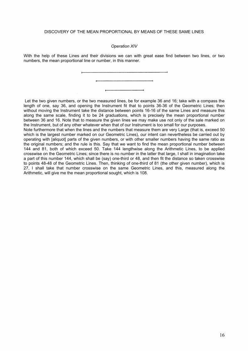
With the help of these Lines and their divisions we can with great ease find between two lines, or two numbers, the mean proportional line or number, in this manner.
Let the two given numbers, or the two measured lines, be for example 36 and 16; take with a compass the length of one, say 36, and opening the Instrument fit that to points 36-36 of the Geometric Lines; then without moving the Instrument take the distance between points 16-16 of the same Lines and measure this along the same scale, finding it to be 24 graduations, which is precisely the mean proportional number between 36 and 16. Note that to measure the given lines we may make use not only of the sale marked on the Instrument, but of any other whatever when that of our Instrument is too small for our purposes. Note furthermore that when the lines and the numbers that measure them are very Large (that is, exceed 50 which is the largest number marked on our Geometric Lines), our intent can nevertheless be carried out by operating with [aliquot] parts of the given numbers, or with other smaller numbers having the same ratio as the original numbers; and the rule is this. Say that we want to find the mean proportional number between 144 and 81, both of which exceed 50. Take 144 lengthwise along the Arithmetic Lines, to be applied crosswise on the Geometric Lines; since there is no number in the latter that large, I shall in imagination take a part of this number 144, which shall be (say) one-third or 48, and then fit the distance so taken crosswise to points 48-48 of the Geometric Lines. Then, thinking of one-third of 81 (the other given number), which is 27, I shall take that number crosswise on the same Geometric Lines, and this, measured along the Arithmetic, will give me the mean proportional sought, which is 108.
16
OF THE STEREOMETRIC LINES,
AND FIRST, HOW BY MEANS OF THESE ALL SIMILAR SOLIDS CAN BE INCREASED OR DIMINISHED IN ANY GIVEN RATIO
Operation XV The present Stereometric Lines are so called because their divisions are according to the ratios of
solid bodies, our to 148; from them we shall collect many uses. The first of these will be that proposed above; that is, given one side of any solid body how we may find the side of another [similar one] that has a given [volume] ratio to it.
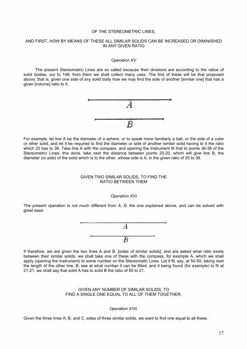
For example, let line A be the diameter of a sphere, or to speak more familiarly a ball, or the side of a cube or other solid, and let it be required to find the diameter or side of another similar solid having to it the ratio which 20 has to 36. Take line A with the compass, and opening the Instrument fit that to points 36-36 of the Stereometric Lines; this done, take next the distance between points 20-20, which will give line B, the diameter (or side) of the solid which is to the other, whose side is A, in the given ratio of 20 to 36.
GIVEN TWO SIMILAR SOLIDS, TO FIND THE RATIO BETWEEN THEM
Operation XVI
The present operation is not much different from A, B, the one explained above, and can be solved with great ease.
If therefore, we are given the two lines A and B, [sides of similar solids], and are asked what ratio exists between their similar solids, we shall take one of these with the compass, for example A, which we shall apply (opening the Instrument) to some number on the Stereometic Lines. Let it fit, say, at 50-50; taking next the length of the other line, B, see at what number it can be fitted, and it being found (for example) to fit at 21-21, we shall say that solid A has to solid B the ratio of 50 to 21.
GIVEN ANY NUMBER OF SIMILAR SOLIDS, TO FIND A SINGLE ONE EQUAL TO ALL OF THEM TOGETHER.
Operation XVII.
Given the three lines A, B, and C, sides of three similar solids, we want to find one equal to all these.
17
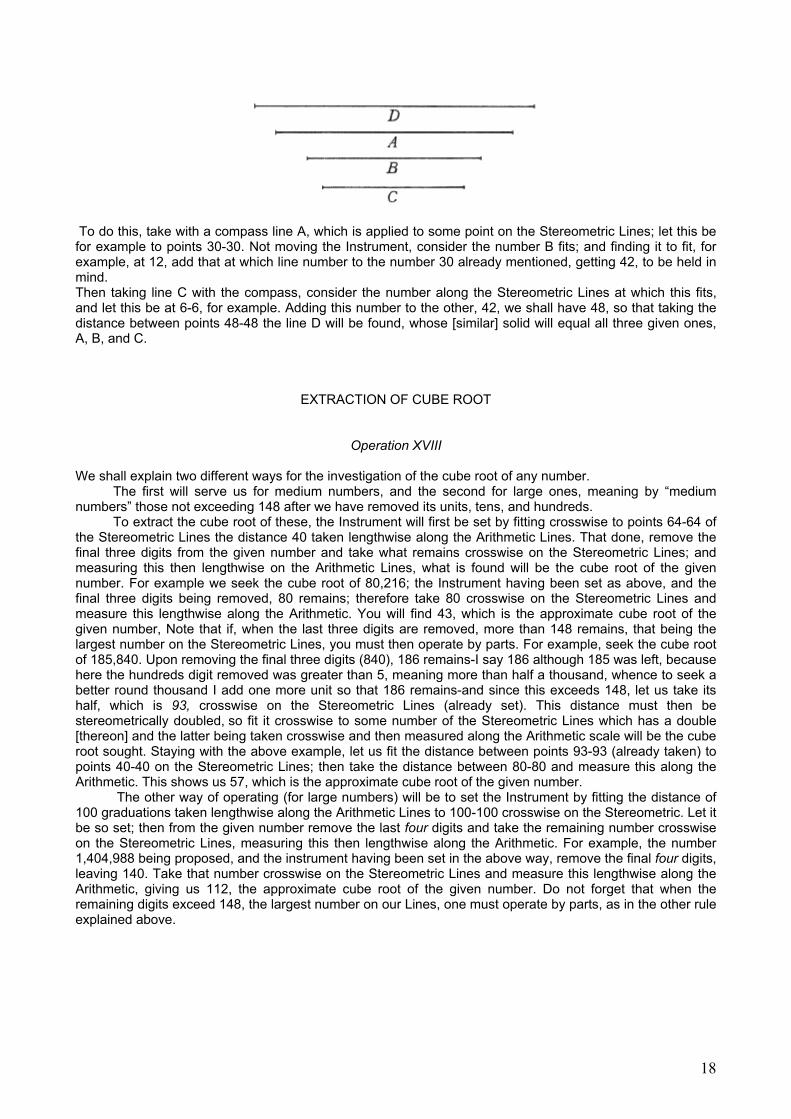
To do this, take with a compass line A, which is applied to some point on the Stereometric Lines; let this be for example to points 30-30. Not moving the Instrument, consider the number B fits; and finding it to fit, for example, at 12, add that at which line number to the number 30 already mentioned, getting 42, to be held in mind. Then taking line C with the compass, consider the number along the Stereometric Lines at which this fits, and let this be at 6-6, for example. Adding this number to the other, 42, we shall have 48, so that taking the distance between points 48-48 the line D will be found, whose [similar] solid will equal all three given ones, A, B, and C.
EXTRACTION OF CUBE ROOT
Operation XVIII
We shall explain two different ways for the investigation of the cube root of any number.
The first will serve us for medium numbers, and the second for large ones, meaning by “medium numbers” those not exceeding 148 after we have removed its units, tens, and hundreds.
To extract the cube root of these, the Instrument will first be set by fitting crosswise to points 64-64 of the Stereometric Lines the distance 40 taken lengthwise along the Arithmetic Lines. That done, remove the final three digits from the given number and take what remains crosswise on the Stereometric Lines; and measuring this then lengthwise on the Arithmetic Lines, what is found will be the cube root of the given number. For example we seek the cube root of 80,216; the Instrument having been set as above, and the final three digits being removed, 80 remains; therefore take 80 crosswise on the Stereometric Lines and measure this lengthwise along the Arithmetic. You will find 43, which is the approximate cube root of the given number, Note that if, when the last three digits are removed, more than 148 remains, that being the largest number on the Stereometric Lines, you must then operate by parts. For example, seek the cube root of 185,840. Upon removing the final three digits (840), 186 remains-I say 186 although 185 was left, because here the hundreds digit removed was greater than 5, meaning more than half a thousand, whence to seek a better round thousand I add one more unit so that 186 remains-and since this exceeds 148, let us take its half, which is 93, crosswise on the Stereometric Lines (already set). This distance must then be stereometrically doubled, so fit it crosswise to some number of the Stereometric Lines which has a double [thereon] and the latter being taken crosswise and then measured along the Arithmetic scale will be the cube root sought. Staying with the above example, let us fit the distance between points 93-93 (already taken) to points 40-40 on the Stereometric Lines; then take the distance between 80-80 and measure this along the Arithmetic. This shows us 57, which is the approximate cube root of the given number.
The other way of operating (for large numbers) will be to set the Instrument by fitting the distance of 100 graduations taken lengthwise along the Arithmetic Lines to 100-100 crosswise on the Stereometric. Let it be so set; then from the given number remove the last four digits and take the remaining number crosswise on the Stereometric Lines, measuring this then lengthwise along the Arithmetic. For example, the number 1,404,988 being proposed, and the instrument having been set in the above way, remove the final four digits, leaving 140. Take that number crosswise on the Stereometric Lines and measure this lengthwise along the Arithmetic, giving us 112, the approximate cube root of the given number. Do not forget that when the remaining digits exceed 148, the largest number on our Lines, one must operate by parts, as in the other rule explained above.
18

DISCOVERY OF TWO MEAN PROPORTIONALS
Operation XIX
When there shall be proposed to us two numbers or two measured lines between which we are to find two others that are the mean proportionals, we shall be able to do this easily by means of the present Lines as will be clear from the following example.
Given the two lines A and D, of which one is for example 108 and the other is 32, take the larger with a compass and fit it, opening the Instrument, to the numbers 108-108; then take the distance between points 32-32, which will give the length of the second line, B; and measuring this by the same scale with which the given lines were measured, 72 will be found. Then to find the third line, C, fit anew points 108-108 on the same Stereometric Lines, this time to the length of B, once again finding the distance between points 32-32; this will now be the magnitude of the third line, C, and measured on the same scale as before, it will be found to give 48 graduations. Notice that it is not necessary to take first the larger rather than the smaller line, but operating with either in the same way you will always find the same [result].
HOW EVERY PARALLELOPIPED CAN BE REDUCED TO A CUBE BY MEANS OF THE STEREOMETRIC LINES
Operation XX
Let there be given the parallelepiped solid whose dimensions are unequal, as 72, 32, and 84; what is sought is the side of the cube equal to it. Take the mean proportional between 72 and 32 in the way explained in Operation 14-that is, take 72 lengthwise along the Arithmetic scale and set this crosswise against 72-72 on the Geometric Lines (although because they do not go that far, you set it against one-half, or 36, and then take next the other number, that is, 32-32, crosswise on the saint Lines, or rather you take its half, or 16-16, having likewise cut the original 72 in half); what is found will clearly be the mean proportional number between 72 and 32. Then measure this along the Arithmetic Lines and you will find it to be 48, whence you now set this crosswise to the same number, 48-48, of the Stereometric Lines, and without altering the Instrument you take crosswise the third number of the given solid, which was 84. The operation will then be completed, because by making this line [the distance between points 84-84] the side of a cube, that will truly be equal to the given solid, Measuring it along the Arithmetic scale you will find it to be about 57 ½.
19
EXPLANATION OF THE METALLIC LINES, MARKED NEXT TO THE STEREOMETRIC
Operation XXI
The present Lines have divisions to which are affixed these symbols: Au, Pb, Ag, Cu, Fe, Sn, Mar,
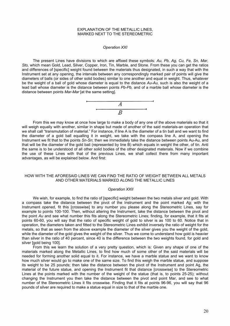
Sto, which mean Gold, Lead, Silver, Copper, Iron, Tin, Marble, and Stone. From these you can get the ratios and differences of [specific] weight found between the materials thus designated, in such a way that with the Instrument set at any opening, the intervals between any correspondingly marked pair of points will give the diameters of balls (or sides of other solid bodies) similar to one another and equal in weight. Thus, whatever be the weight of a ball of gold whose diameter is equal to the distance Au-Au, such is also the weight of a lead ball whose diameter is the distance between points Pb-Pb, and of a marble ball whose diameter is the distance between points Mar-Mar [at the same setting].
From this we may know at once how large to make a body of any one of the above materials so that it
will weigh equally with another, similar in shape but made of another of the said materials-an operation that we shall call “transmutation of material.” For instance, if line A is the diameter of a tin ball and we want to find the diameter of a gold ball equalling it in weight, we take with the compass line A, and opening the Instrument we fit that to the points Sn-Sn; then we immediately take the distance between points Au-Au, and that will be the diameter of the gold ball (represented by line B) which equals in weight the other, of tin. Anti the same is to be understood of all other solid bodies of the other designated materials. Now if we combine the use of these Lines with that of the previous Lines, we shall collect there from many important advantages, as will be explained below. And first:
HOW WITH THE AFORESAID LINES WE CAN FIND THE RATIO OF WEIGHT BETWEEN ALL METALS AND OTHER MATERIALS MARKED ALONG THE METALLIC LINES
Operation XXII
We wish, for example, to find the ratio of [specific] weight between the two metals silver and gold. With
a compass take the distance between the pivot of the Instrument and the point marked Ag; with the Instrument opened, fit this [crosswise] to any number you please along the Stereometric Lines, say for example to points 100-100. Then, without altering the Instrument, take the distance between the pivot and the point Au and see what number this fits along the Stereometric Lines; finding, for example, that it fits at points 60-60, you will say that the ratio of specific weight of gold to silver is as 100 to 60. Notice that in operation, the diameters taken and fitted to the Stereometric Lines exhibit inversely the ratio of weight for the metals, so that as seen from the above example the diameter of the silver gives you the weight of the gold, while the diameter of the gold gives the weight of the silver. Thus we come to understand how gold is heavier than silver in the ratio of 40 percent, since 40 is the difference between the two weights found, for gold and silver [gold being 100].
From this we learn the solution of a very pretty question, which is: Given any shape of one of the materials marked along the Metallic Lines, to find how much of some other of the said materials will be needed for forming another solid equal to it. For instance, we have a marble statue and we want to know how much silver would go to make one of the same size. To find this weigh the marble statue, and suppose its weight to be 25 pounds; then take the distance between the pivot of the Instrument and point Ag, the material of the future statue, and opening the Instrument fit that distance [crosswise] to the Stereometric Lines at the points marked with the number of the weight of the statue (that is, to points 25-25); without changing the Instrument you then take the distance between the pivot and point Mar, and see to what number of the Stereometric Lines it fits crosswise. Finding that it fits at points 96-96, you will say that 96 pounds of silver are required to make a statue equal in size to that of the marble one.
20
COMBINING THE USES OF THE METALLIC AND THE STEREOMETRIC LINES, AND GIVEN TWO SIDES FOR TWO SIMILAR SOLIDS MADE OF
DIFFERENT MATERIALS, TO FIND THE RATIO OF THEIR WEIGHTS
Operation XXIII
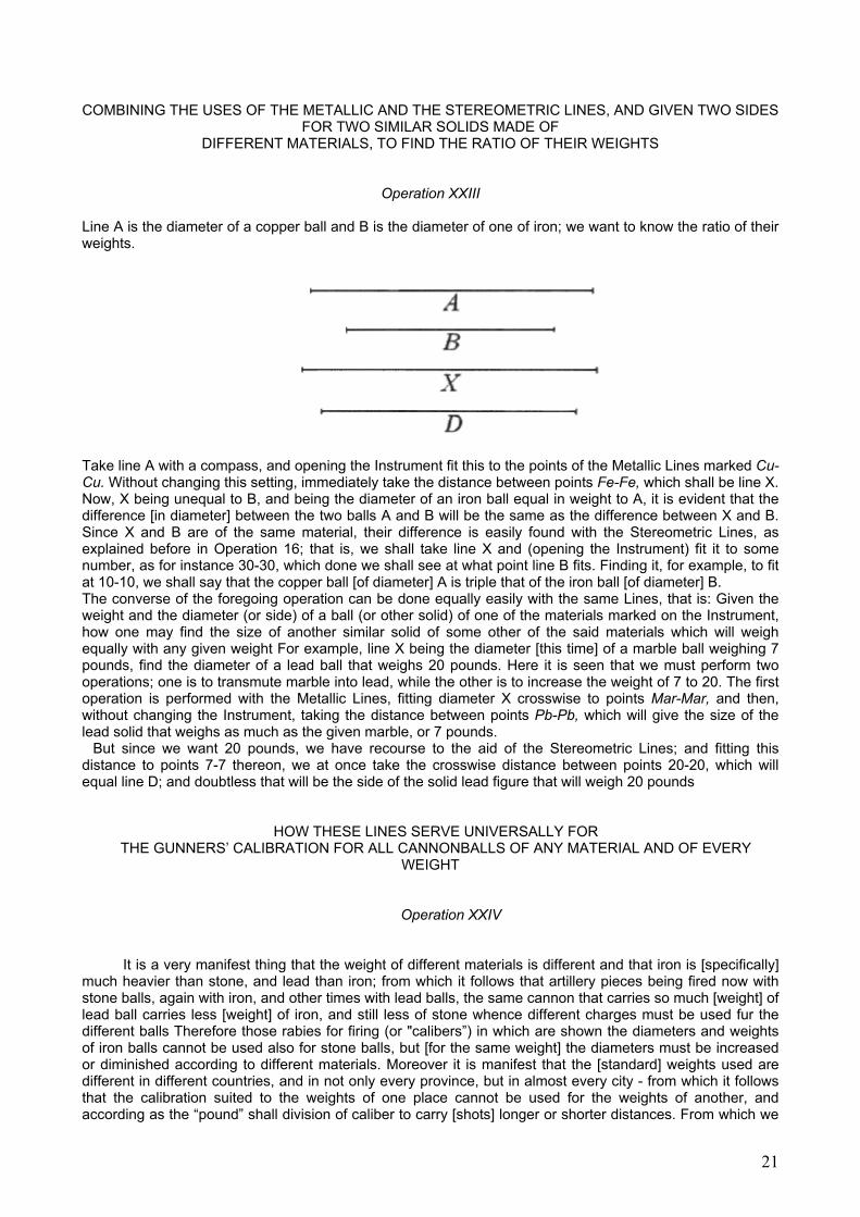
Line A is the diameter of a copper ball and B is the diameter of one of iron; we want to know the ratio of their weights.
Take line A with a compass, and opening the Instrument fit this to the points of the Metallic Lines marked Cu-Cu. Without changing this setting, immediately take the distance between points Fe-Fe, which shall be line X. Now, X being unequal to B, and being the diameter of an iron ball equal in weight to A, it is evident that the difference [in diameter] between the two balls A and B will be the same as the difference between X and B. Since X and B are of the same material, their difference is easily found with the Stereometric Lines, as explained before in Operation 16; that is, we shall take line X and (opening the Instrument) fit it to some number, as for instance 30-30, which done we shall see at what point line B fits. Finding it, for example, to fit at 10-10, we shall say that the copper ball [of diameter] A is triple that of the iron ball [of diameter] B. The converse of the foregoing operation can be done equally easily with the same Lines, that is: Given the weight and the diameter (or side) of a ball (or other solid) of one of the materials marked on the Instrument, how one may find the size of another similar solid of some other of the said materials which will weigh equally with any given weight For example, line X being the diameter [this time] of a marble ball weighing 7 pounds, find the diameter of a lead ball that weighs 20 pounds. Here it is seen that we must perform two operations; one is to transmute marble into lead, while the other is to increase the weight of 7 to 20. The first operation is performed with the Metallic Lines, fitting diameter X crosswise to points Mar-Mar, and then, without changing the Instrument, taking the distance between points Pb-Pb, which will give the size of the lead solid that weighs as much as the given marble, or 7 pounds.
But since we want 20 pounds, we have recourse to the aid of the Stereometric Lines; and fitting this distance to points 7-7 thereon, we at once take the crosswise distance between points 20-20, which will equal line D; and doubtless that will be the side of the solid lead figure that will weigh 20 pounds
HOW THESE LINES SERVE UNIVERSALLY FOR THE GUNNERS’ CALIBRATION FOR ALL CANNONBALLS OF ANY MATERIAL AND OF EVERY
WEIGHT
Operation XXIV
It is a very manifest thing that the weight of different materials is different and that iron is [specifically] much heavier than stone, and lead than iron; from which it follows that artillery pieces being fired now with stone balls, again with iron, and other times with lead balls, the same cannon that carries so much [weight] of lead ball carries less [weight] of iron, and still less of stone whence different charges must be used fur the different balls Therefore those rabies for firing (or "calibers”) in which are shown the diameters and weights of iron balls cannot be used also for stone balls, but [for the same weight] the diameters must be increased or diminished according to different materials. Moreover it is manifest that the [standard] weights used are different in different countries, and in not only every province, but in almost every city - from which it follows that the calibration suited to the weights of one place cannot be used for the weights of another, and according as the “pound” shall division of caliber to carry [shots] longer or shorter distances. From which we
21
be greater or less in one place than another, it will be necessary for fixed may conclude that caliber adapted to any kind of material and every difference in weigh must necessarily be variable and capable of increase or decrease. Such is precisely what is marked on our instrument; for opening this more, or less, the intervals between the divisions found on it increase or diminish without in any way changing their ratios. Having stated these things generally, let us pass to the, particular application or this calibration to any differences in weight and to all the various materials. And since one can come to knowledge of anything unknown only by means of something else, known, it is necessary to know [in our case] only the diameter of a single ball, of any material whatever, and any weight that corresponds to the “pounds’ customary in the country where we wish to use our Instrument. From that single diameter we shall, by means of our calibration, come to know the weight of any other ball, of whatever other material - meaning, however, materials marked on our Instrument.
Now the manner of obtaining such knowledge may be made manifest easily by an example. Suppose for instance that we are at Venice, and we wish to make use of our calibration to know the range of some artillery pieces. First we get the diameter and the weight of a ball made of any of the materials designated on our Instrument; suppose for instance that we have the diameter of a 10-pound lead ball in Venetian weight. This diameter we shall mark by two points [scratched] along the side of one arm of the Instrument. Then when we wish to accommodate and adjust our calibration in such a way that by taking the bore of a [Venetian] piece of artillery and carrying this [measurement] to our calibration, we learn how many pounds of lead ball this [gun] carries, we need only take on a compass that diameter of ten pounds of lead (already marked along the side of our Instrument) and then open the Instrument until the said diameter fits to points 10-10 of the Stereometric Lines. Set in that way, those Lines will serve us for exact calibration, so that given the diameter of the mouth of any artillery piece, and transferring it to the said calibration, we shall know (from the number of the points to which it fits) how many pounds of lead ball the said cannon will bear. And if we want to set the Instrument so that the calibration shall correspond to iron balls, then we still take the same diameter of ten pounds of lead marked on the side, and fit this [crosswise] to the points marked Pb-Pb on the Metallic Lines; then without changing the Instrument we shall take with a compass the distance between the points marked Fe-Fe, which will be the diameter of an iron ball weighing ten pounds. Opening the Instrument, this diameter will be fitted to the points marked 10-10 on the Stereometric Lines, and then said Lines will be exactly set for calibration of iron balls. By similar operations the Instrument can be set for stone balls.
Notice that since it is necessary to mark along the side of the Instrument various diameters of balls corresponding to the [standard] weights of various countries, we should in order to avoid confusion always mark diameters of balls of lead weighing ten pounds, which we shall find to be larger or smaller according to the differences in [local] weights. It will not be difficult to mark down these diameters without the necessity of actually finding ten-pound lead balls, by what was taught before in Operation 23. There, given the diameter of a ball of whatsoever weight and made of any material, we saw how one finds the diameter of any other, of different weight and of any material-meaning always those materials marked on the Metallic Lines. Thus, finding ourselves in any country, provided only that we can find a ball of marble or stone or any other material designated on our Instrument, we can instantly get the diameter of a ten-pound lead ball [in that country’s weight].
HOW, GIVEN A BODY OF ANY MATERIAL, WE CAN FIND ALL THE PARTICULAR MEASURES OF ONE
OF DIFFERENT MATERIAL THAT SHALL WEIGH A GIVEN AMOUNT
Operation XXV Among the uses that can be drawn from these same, lines, one is that we may increase or diminish
solid shapes according to any desired ratio, changing the material or leaving it unchanged, as will he understood from the ensuing example. We are given a little tin model of a cannon from which we must derive all the particular measurements for a large copper cannon weighing, say, 5,000 pounds. First we shall weigh our little tin model; let its weight be 17 pounds. Next we take one of its measurements, whichever you prefer; let this be for example the thickness of the cannon at its mouth. Opening the Instrument, we apply this to the points Sn-Sn of the Metallic Lines, tin being the material of the given model; and since the large cannon is to be made of copper, we at once take the distance between points Cu-Cu, which will be the thickness at the mouth of a copper cannon that would weigh the same as the tin one. But since it is to weigh 5,000 pounds, and not 17 like this tin one, we next have recourse to the Stereometric Lines and fit that distance just found between the points Cu-Cu) to the points marked 17-17. Without moving the Instrument we then take the distance between points 100-100, which will give the thickness at the mouth of a [copper] cannon weighing 100 pounds. But we want the weight to be 5,000 pounds, whence this distance must be increased in the ratio
22
of 50:1. Therefore opening the Instrument farther, we put this [last distance] at same number for which there is another [on the Stereometric Lines] fifty times as great, as would be the case if we fitted it to the points 2-2 and then took the distance between points 100-100, which would doubtless be the measure of the thickness that must be given at the mouth. In this order will be found all the particular measurements for all other parts, such as the throat, the trunnions, the breech, and so on.
No less can we find the length of the cannon, although we cannot open our Instrument to any such distance. To find this, we take on our little model not the entire length, but only a part, such as one-eighth or one-tenth or the like; this may be increased in the way already explained, to show us ultimately one-eighth or one-tenth of the whole length of the large cannon.
But in this [operation] another difficulty [about metals] may arise. Yet our Metallic Lines, designed so as to give measures for transmuting one simple metal into another can do the same for an alloy of metals when in the above example we must make the cannon not of pure copper, but of metal mixing copper and tin, as it is the common custom to do. Wherefore, for complete satisfaction, we shall show how, with the aid of those same Metallic Lines, we can find the measurements for any alloy just as for a simple metal. This will be done by adding two tiny points along the Metallic Lines-and I mean very tiny, so that we may remove them after they have served our purpose. Suppose, for example, that the cannon we want to make is to be not of copper (as previously assumed), but must be cast from bronze, in an alloy of three parts copper to one of tin. Then we must carefully divide, on both arms, that short line between the points marked Cu and Sn into four parts, leaving three of these on the side Sn and only one toward Cu, and precisely there making our tiny point appear. We then use this point (marked, as was said, on both the Metallic Lines) for our transmutation of metal, just as above we used the points Cu-Cu. Using this rule we can, as occasion arises, mark new points for any alloys of two metals in any ratio desired.
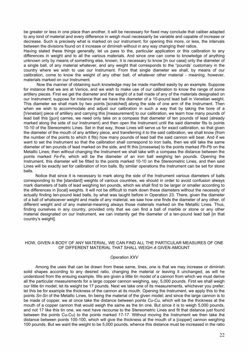
It will not be irrelevant and without useful purpose to note, especially when one must make the transmutation into some metal mixed and alloyed of two others in any ratio, that when a single one of the measurements sought has been found by working with great precision in the way explained above, one may on the strength of this unique determined measurement go on to find all the rest by means of the Arithmetic Lines [alone], in a way not much different from that explained in Operation 3. For example, line A was the diameter or thickness of the mouth of the given cannon model, and line B was then found to be the mouth of the 5,000-pound cannon to be made of a metal containing three parts of copper to two of tin.
I say next that to find all the remaining dimensions, we may use the Arithmetic Lines, taking line B and applying it crosswise to any point along those Arithmetic Lines, and the greater the number chosen the better it will be. So let us fit B to the last point, that is, at 250-250, and without moving the Instrument let us see where line A fits crosswise; say this is at 44-44. From this we learn that since A of the model measures 44 graduations, what must correspond to it in the real cannon will be 250 of those same graduations. This same ratio must then hold for every other measurement, whence to find (for example) the thickness of the throat of the real cannon you will take that thickness from the little model and fit it crosswise to points 44-44 of the Arithmetic Lines, taking then (also crosswise) the distance between points 250-250, which will give the throat of the large cannon. By the same rule will be found all the other measurements.
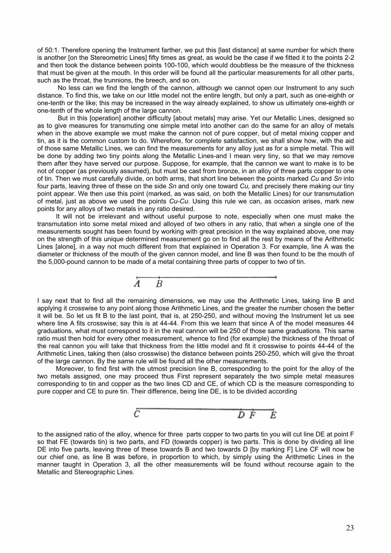
Moreover, to find first with the utmost precision line B, corresponding to the point for the alloy of the two metals assigned, one may proceed thus First represent separately the two simple metal measures corresponding to tin and copper as the two lines CD and CE, of which CD is the measure corresponding to pure copper and CE to pure tin. Their difference, being line DE, is to be divided according
to the assigned ratio of the alloy, whence for three parts copper to two parts tin you will cut line DE at point F so that FE (towards tin) is two parts, and FD (towards copper) is two parts. This is done by dividing all line DE into five parts, leaving three of these towards B and two towards D [by marking F] Line CF will now be our chief one, as line B was before, in proportion to which, by simply using the Arithmetic Lines in the manner taught in Operation 3, all the other measurements will be found without recourse again to the Metallic and Stereographic Lines.
23
OF THE POLYGRAPHIC LINES,
AND HOW BY THESE WE CAN DESCRIBE REGU LAR POLYGONS; THAT IS, FIGURES OF MANY EQUAL SIDES AND ANGLES
Operation XXVI
Turning the Instrument, over we see the innermost Lines on its other face, called Polygraphic from
their principal use, which is to describe on a given line figures having as many equal sides (and angles) as required. This is easily done by taking with a compass the length of the given line and fitting it to the points marked 6-6; next, without changing the Instrument, we take the distance between the points marked With the same number as the number of sides of the figure we wish to draw. For instance, to describe a [regular] figure of 7 sides we take the distance between points 7-7, which will be the radius of the circle containing the heptagon to be drawn. Place one leg of the compass first at one end and then at the other end of the given line and trace with it a short intersection of arcs; then taking this as center we shall describe with the same compass-opening a faint circle. Passing through the ends of the given line, this will contain that line exactly 7 times inside its circumference, whereby the heptagon is drawn.
DIVISION OF A CIRCLE INTO AS MANY PARTS AS IS DESIRED
Operation XXVII
With these lines the circumference can be divided into many parts, working by the converse of the
preceding operation. Take the radius of the given circle and fit it to the number designating the parts into which the circle is to be divided; then take always the distance between points 6-6 [on the Polygraphic Lines so separated] and this will divide the circumference into the desired [number of] parts.
24

EXPLANATION OF THE TETRAGONIC LINES,
AND HOW BY THEIR MEANS ONE MAY SQUARE THE CIRCLE, OR ANY OTHER REGULAR FIGURE, AND MAY ALSO TRANSFORM ALL THESE, ONE INTO ANOTHER
Operation XXVIII
Tetragonic Lines are so called from their principal use, which is to square all regular areas and the circle as well, which is done by an easy operation. For when we wish to construct a square equal to a given circle, all we have to do is to take its radius with a compass, and opening the Instrument fit this to the two points along the Tetragonic Lines marked by two tiny circles; then, not moving the Instrument, if you take on the compass the distance between the points marked 4-4 on those Lines, you will have the side of a square equal [in area] to the given circle. Likewise if you want the side of the pentagon, or the hexagon, equal to the same circle, you will take the distance between points 5-5, or 6-6; for they are respectively the sides of the pentagon and the hexagon equal to that same circle.
Moreover if we want the converse (given a square or other regular polygon, to find a circle equal to it), we take one side of the given polygons and fit it to the points of the Tetragonic Lines corresponding to the number of sides of the given figure; then, without moving the Instrument, take the distance between the little circle marks, and by making this the radius you will describe the circle equal to the given polygon. In conclusion, you can in this way find the side of any regular figure that is equal to any other. For example, we wish to construct an octagon equal to a given pentagon [both regular]. The Instrument is set so that the side of the given pentagon fits at points 5-5, and without changing the Instrument the distance between points 8-8 will give the side of the octagon sought.
GIVEN DIFFERENT REGULAR FIGURES, HOW EVER DISSIMILAR TO ONE ANOTHER, HOW TO CONSTRUCT A SINGLE ONE EQUAL TO ALL OF
THEM TOGETHER
Operation XXIX
Solution of the present problem depends on the preceding one and on Operation to, explained before. Let there be given to us a circle, a triangle, a pentagon, and a hexagon; we are asked to find one square equal to all the said figures [combined]. First, by the preceding operation we find separately four squares, equal to the given four figures; then, by Operation 10, we find a single square equal to those four, which will doubtless be equal to all four given figures.
HOW ONE MAY MAKE ANY DESIRED REGULAR FIGURE THAT EQUALS ANY GIVEN IRREGULAR (BUT RECTILINEAR) FIGURE
Operation XXX
The present operation is no less useful than interesting, showing us not lust the way to square all irregular [rectilinear] figures, but how to reduce them either to a circle or to any other regular figure you like. Since every rectilinear figure is resolvable into triang1es once we can make a square equal to any triangle we shall make separately individual squares, equal to each of the triangles into which the given rectilinear figure is resolved, and then by Operation 10 we reduce all these squares into a single square, and obviously the square will have been found that is equal to the given rectilinear figure. By means of the Tetragonic Lines we can at will convert that square in turn into a circle, a pentagon, or any other regular rectilinear figure. Thus the solution of the present question is reduced to our having to find a square equal to any given triangle, which you will have very easily from the ensuing lemma.
25
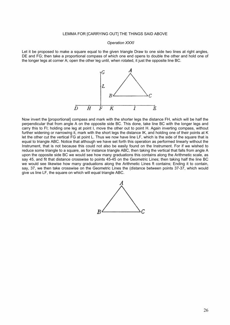
LEMMA FOR [CARRYING OUT] THE THINGS SAID ABOVE
Operation XXXI
Let it be proposed to make a square equal to the given triangle Draw to one side two lines at right angles, DE and FG; then take a proportional compass of which one end opens to double the other and hold one of the longer legs at corner A; open the other leg until, when rotated, it just the opposite line BC.
Now invert the [proportional] compass and mark with the shorter legs the distance FH, which will be half the perpendicular that from angle A on the opposite side BC. This done, take line BC with the longer legs and carry this to FI; holding one leg at point I, move the other out to point H. Again inverting compass, without further widening or narrowing it, mark with the short legs the distance IK, and holding one of their points at K let the other cut the vertical FG at point L. Thus we now have line LF, which is the side of the square that is equal to triangle ABC. Notice that although we have set forth this operation as performed linearly without the Instrument, that is not because this could not also be easily found on the Instrument. For if we wished to reduce some triangle to a square, as for instance triangle ABC, then taking the vertical that falls from angle A upon the opposite side BC we would see how many graduations this contains along the Arithmetic scale, as say 45, and fit that distance crosswise to points 45-45 on the Geometric Lines; then taking half the line BC we would see likewise how many graduations along the Arithmetic Lines ft contains; Ending it to contain, say, 37, we then take crosswise on the Geometric Lines the (distance between points 37-37, which would give us line LF, the square on which will equal triangle ABC.
26

OF THE ADDED LINES,
FOR THE QUADRATURE OF SEGMENTS OF A CIRCLE AND OF FIGURES CONTAINING PARTS OF CIRCUMFERENCES, OR STRAIGHT AND CURVED LINES TOGETHER
Operation XXXII There remain finally the Added Lines, so called because they add to the Tetragonic Lines what with
those was left to be desired-that is, a way of squaring segments of circles and the other figures mentioned in the heading above, which will be more specifically explained below. These Added Lines are marked with two series of numbers, of which the outer series begins at this mark , followed by the numbers 1, 2, 3, 4, and so on out to 18. The inner series begins from this mark going on then to 1, 2,3,4, and so on, out to 18. By means of these Lines we can (for the first time) square any given segment of a circle not more than a semicircle. In order that this may be better understood, their use will be explained by example.
We wish, for instance to find the square equal to the segment of a circle, ABC. Bisect its chord AC at point D, and take the distance DC with a compass. Opening the Instrument, fit this across the points marked DD and leaving the Instrument at this setting, take next the altitude of the segment (that is, line DB) and see at which points of the outer scale this fits crosswise. Let this be, say, at points 2-2. This done, we must next take with the compass the distance between points 2-2 of the inner scale and form our square on a line of that length, which [square] will be equal to the segment ABC. Now if we have an area contained by two segments of circles with a common chord, as in the next diagram ABCD, we could easily reduce this to a square by drawing the chord AC which divides this figure into two circular segments, whereupon by the rule already given there are found two squares equal to the two separate segments which by recourse to Operation 10 are reduced to a single square, completing the task. By a not dissimilar operation we can also square any sector of a circle; for drawing the chord of its arc cuts that into one circular segment and one triangle, two parts which can easily be reduced to two squares by the things already taught, and those two then [reduced] to a single square.
Finally it remains for us to show how the same Lines can serve us to square a segment larger than a semicircle, or a trapezium contained by two straight lines and two arcs (like that in the next figure, ABCD), or the lune similar to X; all of which operations have the same resolution. As to the segment larger than a semicircle, if we square the excluded smaller segment in the foregoing manner, and subtract such a square from the square equal to the entire circle, the square equal to the difference will obviously be equal to the larger segment of the circle. Likewise, having found the square equal to the whole segment BAFDC and subtracted from this the square equal to the segment AFD, the remainder will equal the trapezium [ABCD]. And proceeding similarly for the lune X, draw the common chord of the two segments of circles and take separately the squares equal to those two segments; their difference will be the square equal to the lune. As to finding the difference between two given squares and reducing this to another square, that was explained by use of the Geometric Lines in Operation XI.
27
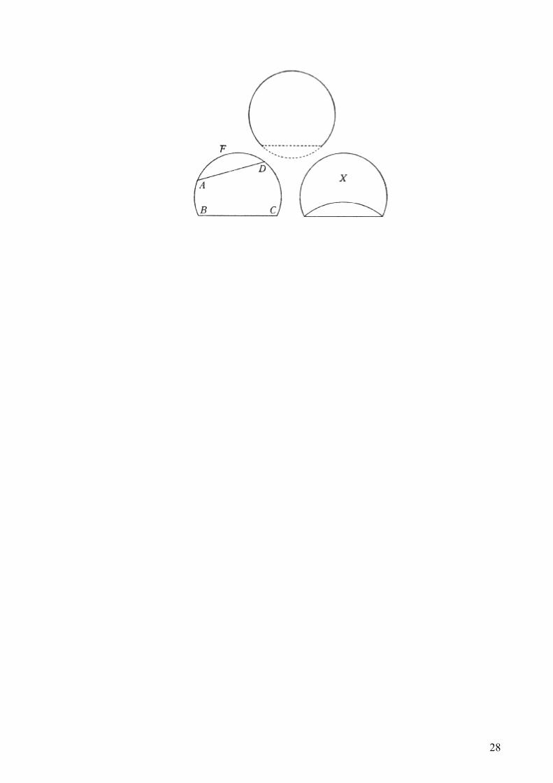
28

ON THE OPERATIONS OF THE QUADRANT By attaching the Quadrant Arc to the Instrument we have the gunners’ Squadra, divided as is
customary into 12 “points”. The ordinary use of this is to place one of its legs in the bore of a cannon, having first hung a plumb bob by a thread from the pivot of the Instrument; this thread cutting the circumference, we are shown the elevation of the cannon in “points” as 1,2, or 3. But since to use the Squadra in this way is not without peril, [the gunner] having to go outside the ramparts or shields and expose himself to the enemy, another way has been thought of to do the same thing in safety-that is, by applying the Squadra near the fuse of the cannon [to its upper surface]. But because the internal bore is not parallel with the outer surface, the metal being thicker near the breech, one must provide against error by lengthening the leg of the Squadra on the side toward the mouth, adding to this [length] by a movable footing. Thus, placing the Squadra [upright] near the fuse [of a level cannon], we lengthen the forward leg by this footing until the vertical [thread] cuts point 6 [on the usual scale of 12]; and fixing the footing with its set-screw, we mark a little line on the side of the Instrument at the end of the cursor carrying the footing, so that on every occasion of its use [with this cannon] we can place it exactly. Then when we want to fire “at one point” of elevation, the cannon is elevated until the thread cuts the number 7; and if we want “two points” it must cut the 8, and so on. Next following is the division of the Astronomical Quadrant, whose use (having been treated by many others) will not be explained here. The circumference that comes next is seen to be divided by some slanted lines, used for taking the slope of any [rampart] wall, beginning with those which for every ten units of height have one unit of horizontal advance and going on out to those which have one unit of horizontal advance for every 1 1/2 units of height. To employ this [scale of the] Instrument we must hang the [plumb] line from that little hole which is seen at the beginning of the gunners’ Squadra; then, approaching the sloping wall, hold the other edge of the Instrument against it and note where the thread cuts [this scale]; if it cuts at number 5, for example, we shall say that the wall has one braccio20 of horizontal advance for every 5 braccia of height; or, cutting at number 4, that it has one unit of horizontal advance for every 4 of height.
29
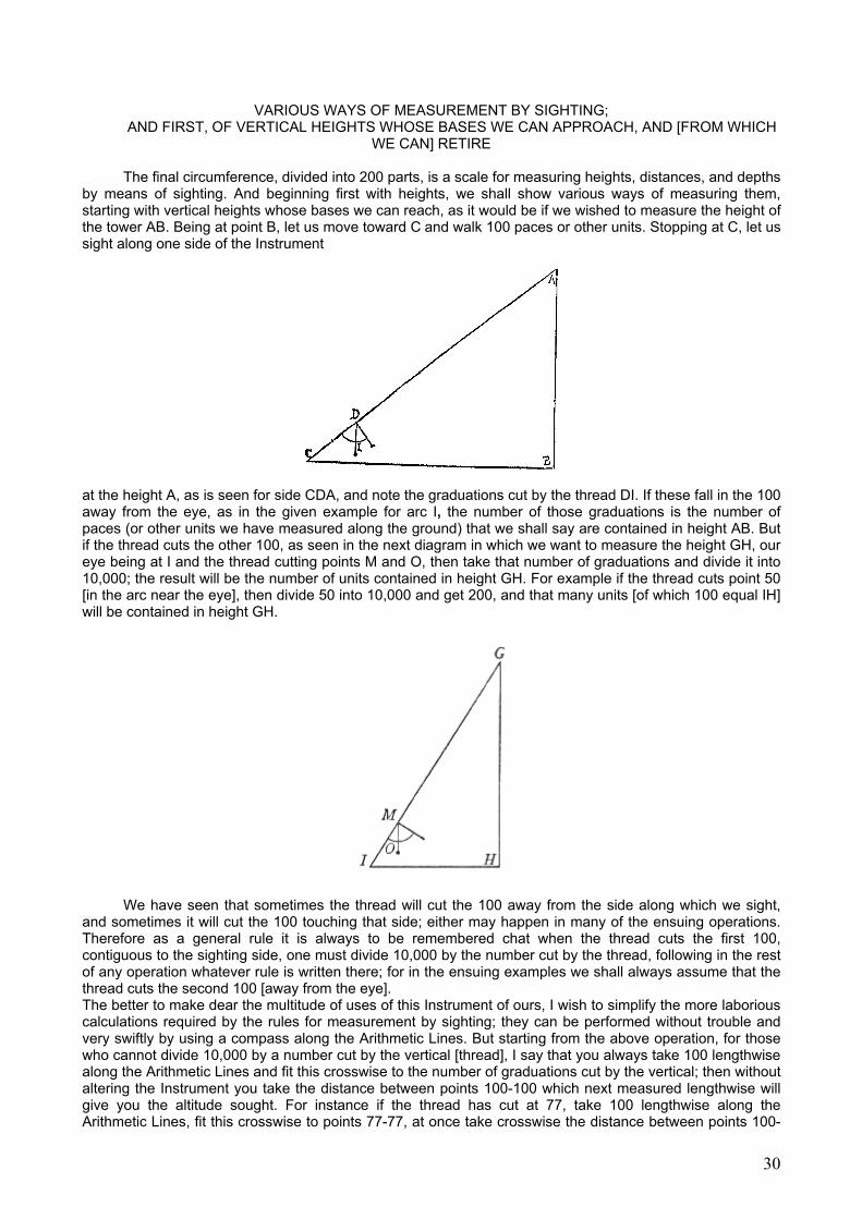
VARIOUS WAYS OF MEASUREMENT BY SIGHTING; AND FIRST, OF VERTICAL HEIGHTS WHOSE BASES WE CAN APPROACH, AND [FROM WHICH
WE CAN] RETIRE The final circumference, divided into 200 parts, is a scale for measuring heights, distances, and depths
by means of sighting. And beginning first with heights, we shall show various ways of measuring them, starting with vertical heights whose bases we can reach, as it would be if we wished to measure the height of the tower AB. Being at point B, let us move toward C and walk 100 paces or other units. Stopping at C, let us sight along one side of the Instrument
at the height A, as is seen for side CDA, and note the graduations cut by the thread DI. If these fall in the 100 away from the eye, as in the given example for arc I, the number of those graduations is the number of paces (or other units we have measured along the ground) that we shall say are contained in height AB. But if the thread cuts the other 100, as seen in the next diagram in which we want to measure the height GH, our eye being at I and the thread cutting points M and O, then take that number of graduations and divide it into 10,000; the result will be the number of units contained in height GH. For example if the thread cuts point 50 [in the arc near the eye], then divide 50 into 10,000 and get 200, and that many units [of which 100 equal IH] will be contained in height GH.
We have seen that sometimes the thread will cut the 100 away from the side along which we sight, and sometimes it will cut the 100 touching that side; either may happen in many of the ensuing operations. Therefore as a general rule it is always to be remembered chat when the thread cuts the first 100, contiguous to the sighting side, one must divide 10,000 by the number cut by the thread, following in the rest of any operation whatever rule is written there; for in the ensuing examples we shall always assume that the thread cuts the second 100 [away from the eye]. The better to make dear the multitude of uses of this Instrument of ours, I wish to simplify the more laborious calculations required by the rules for measurement by sighting; they can be performed without trouble and very swiftly by using a compass along the Arithmetic Lines. But starting from the above operation, for those who cannot divide 10,000 by a number cut by the vertical [thread], I say that you always take 100 lengthwise along the Arithmetic Lines and fit this crosswise to the number of graduations cut by the vertical; then without altering the Instrument you take the distance between points 100-100 which next measured lengthwise will give you the altitude sought. For instance if the thread has cut at 77, take 100 lengthwise along the Arithmetic Lines, fit this crosswise to points 77-77, at once take crosswise the distance between points 100-
30
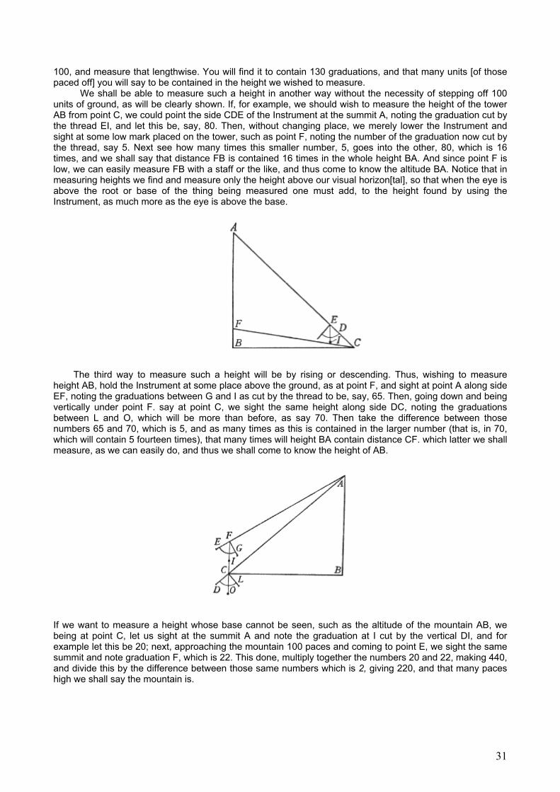
100, and measure that lengthwise. You will find it to contain 130 graduations, and that many units [of those paced off] you will say to be contained in the height we wished to measure.
We shall be able to measure such a height in another way without the necessity of stepping off 100 units of ground, as will be clearly shown. If, for example, we should wish to measure the height of the tower AB from point C, we could point the side CDE of the Instrument at the summit A, noting the graduation cut by the thread EI, and let this be, say, 80. Then, without changing place, we merely lower the Instrument and sight at some low mark placed on the tower, such as point F, noting the number of the graduation now cut by the thread, say 5. Next see how many times this smaller number, 5, goes into the other, 80, which is 16 times, and we shall say that distance FB is contained 16 times in the whole height BA. And since point F is low, we can easily measure FB with a staff or the like, and thus come to know the altitude BA. Notice that in measuring heights we find and measure only the height above our visual horizon[tal], so that when the eye is above the root or base of the thing being measured one must add, to the height found by using the Instrument, as much more as the eye is above the base.
The third way to measure such a height will be by rising or descending. Thus, wishing to measure height AB, hold the Instrument at some place above the ground, as at point F, and sight at point A along side EF, noting the graduations between G and I as cut by the thread to be, say, 65. Then, going down and being vertically under point F. say at point C, we sight the same height along side DC, noting the graduations between L and O, which will be more than before, as say 70. Then take the difference between those numbers 65 and 70, which is 5, and as many times as this is contained in the larger number (that is, in 70, which will contain 5 fourteen times), that many times will height BA contain distance CF. which latter we shall measure, as we can easily do, and thus we shall come to know the height of AB.
If we want to measure a height whose base cannot be seen, such as the altitude of the mountain AB, we being at point C, let us sight at the summit A and note the graduation at I cut by the vertical DI, and for example let this be 20; next, approaching the mountain 100 paces and coming to point E, we sight the same summit and note graduation F, which is 22. This done, multiply together the numbers 20 and 22, making 440, and divide this by the difference between those same numbers which is 2, giving 220, and that many paces high we shall say the mountain is.
31
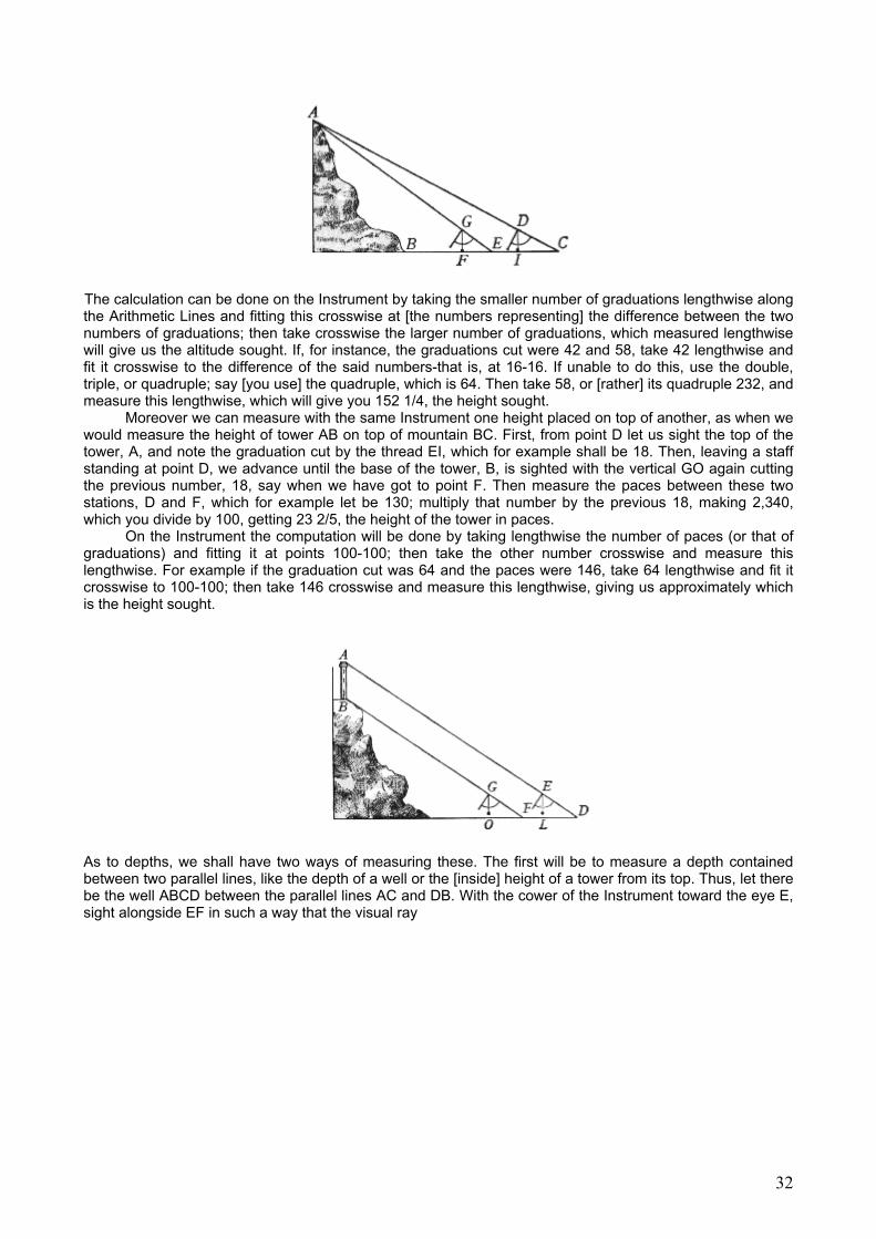
The calculation can be done on the Instrument by taking the smaller number of graduations lengthwise along the Arithmetic Lines and fitting this crosswise at [the numbers representing] the difference between the two numbers of graduations; then take crosswise the larger number of graduations, which measured lengthwise will give us the altitude sought. If, for instance, the graduations cut were 42 and 58, take 42 lengthwise and fit it crosswise to the difference of the said numbers-that is, at 16-16. If unable to do this, use the double, triple, or quadruple; say [you use] the quadruple, which is 64. Then take 58, or [rather] its quadruple 232, and measure this lengthwise, which will give you 152 1/4, the height sought.
Moreover we can measure with the same Instrument one height placed on top of another, as when we would measure the height of tower AB on top of mountain BC. First, from point D let us sight the top of the tower, A, and note the graduation cut by the thread EI, which for example shall be 18. Then, leaving a staff standing at point D, we advance until the base of the tower, B, is sighted with the vertical GO again cutting the previous number, 18, say when we have got to point F. Then measure the paces between these two stations, D and F, which for example let be 130; multiply that number by the previous 18, making 2,340, which you divide by 100, getting 23 2/5, the height of the tower in paces.
On the Instrument the computation will be done by taking lengthwise the number of paces (or that of graduations) and fitting it at points 100-100; then take the other number crosswise and measure this lengthwise. For example if the graduation cut was 64 and the paces were 146, take 64 lengthwise and fit it crosswise to 100-100; then take 146 crosswise and measure this lengthwise, giving us approximately which is the height sought.
As to depths, we shall have two ways of measuring these. The first will be to measure a depth contained between two parallel lines, like the depth of a well or the [inside] height of a tower from its top. Thus, let there be the well ABCD between the parallel lines AC and DB. With the cower of the Instrument toward the eye E, sight alongside EF in such a way that the visual ray
32
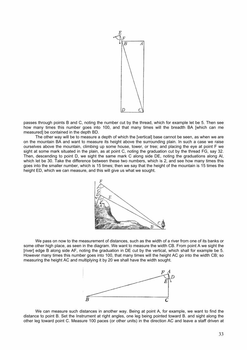
passes through points B and C, noting the number cut by the thread, which for example let be 5. Then see how many times this number goes into 100, and that many times will the breadth BA [which can me measured] be contained in the depth BD.
The other way will be to measure a depth of which the [vertical] base cannot be seen, as when we are on the mountain BA and want to measure its height above the surrounding plain. In such a case we raise ourselves above the mountain, climbing up some house, tower, or tree; and placing the eye at point F we sight at some mark situated in the plain, as at point C, noting the graduation cut by the thread FG, say 32. Then, descending to point D, we sight the same mark C along side DE, noting the graduations along Al, which let be 30. Take the difference between these two numbers, which is 2, and see how many times this goes into the smaller number, which is 15 times; then we say that the height of the mountain is 15 times the height ED, which we can measure, and this will give us what we sought.
We pass on now to the measurement of distances, such as the width of a river from one of its banks or
some other high place, as seen in the diagram. We want to measure the width CB. From point A we sight the [river] edge B along side AF, noting the graduation in DE cut by the vertical, which shall for example be 5. However many times this number goes into 100, that many times will the height AC go into the width CB; so measuring the height AC and multiplying it by 20 we shall have the width sought.
We can measure such distances in another way. Being at point A, for example, we want to find the distance to point B. Set the Instrument at right angles, one leg being pointed toward B. and sight along the other leg toward point C. Measure 100 paces (or other units) in the direction AC and leave a staff driven at
33
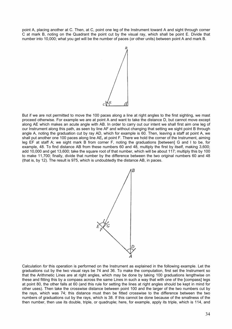
point A, placing another at C. Then, at C, point one leg of the Instrument toward A and sight through corner C at mark B, noting on the Quadrant the point cut by the visual ray, which shall be point E. Divide that number into 10,000; what you get will be the number of paces (or other units) between point A and mark B.
But if we are not permitted to move the 100 paces along a line at right angles to the first sighting, we mast proceed otherwise. For example we are at point A and want to take the distance D, but cannot move except along AE which makes an acute angle with AB. In order to carry out our intent we shall first aim one leg of our Instrument along this path, as seen by line AF and without changing that setting we sight point B through angle A, noting the graduation cut by ray AD, which for example is 60. Then, leaving a staff at point A, we shall put another one 100 paces along line AE, at point F. There we hold the corner of the Instrument, aiming leg EF at staff A; we sight mark B from corner F, noting the graduations [between] G and I to be, for example, 48. To find distance AB from these numbers 60 and 48, multiply the first by itself, making 3,600; add 10,000 and get 13,600; take the square root of that number, which will be about 117; multiply this by 100 to make 11,700; finally, divide that number by the difference between the two original numbers 60 and 48 (that is, by 12). The result is 975, which is undoubtedly the distance AB, in paces.
Calculation for this operation is performed on the Instrument as explained in the following example. Let the graduations cut by the two visual rays be 74 and 36. To make the computation, first set the Instrument so that the Arithmetic Lines are at right angles, which may be done by taking 100 graduations lengthwise on these and fitting this by a compass across the same Lines in such a way that with one of the [compass] legs at point 80, the other falls at 60 (and this rule for setting the lines at right angles should be kept in mind for other uses). Then take the crosswise distance between point 100 and the larger of the two numbers cut by the rays, which was 74; this distance must then be fitted crosswise to the difference between the two numbers of graduations cut by the rays, which is 38. If this cannot be done because of the smallness of the then number, then use its double, triple, or quadruple; here, for example, apply its triple, which is 114, and
34

then take the crosswise distance between points 100-100. Measure that distance lengthwise; taken three times, this will be the distance sought. Measured in the present example, you will find it to be 109, so that tripled it will give you 327, which is approximately the distance we wanted to measure.
Next let us see how to measure the distance between two places remote from us, and first we shall explain the procedure when from some place we can see them both along the same straight line. This is done in the present example, where we wish to measure the distance between points A and B. which from point C appear along the same line CBA First set one leg of the Instrument in that direction, and sight [perpendicularly] along the other leg toward D, where a staff is placed 100 units from C. and a similar one at C. Going to point D, we hold one leg of the Instrument in the direction DC, sighting from corner D the two places B and A, and noting the numbers cut by these rays, which are, say, 20 and 25. Divide 10000 by those numbers, and the difference between the two results will be the distance BA.
But if we warn to measure the distance between two places C and D and arc unable to reach any place from which they appear in the same direction, we proceed in such cases as next described. Assume that standing at place A, we want to investigate the distance between the two places C and D First, set one leg of the Instrument as shown by line AEC, sight through an angle the other point, D, and note the graduations [between] E and F (cut by ray AFD), these being for example
20. Without moving the Instrument, sight along the other leg toward B, planting a staff at A and having another a placed along the direction AB. Then, walking in that direction, we get to B, having departed from the second staff just enough so that again pointing one leg of the Instrument along line BA, the other leg points at D (as shown by line BD). From corner B we sight point C, noting the number cut by tar BG, which (say) is 15. Finally, the number of paces between the two stations A and B is measured, which in our example is 160. Now, coming to the arithmetical work, first multiply the number of paces between the two stations (that is, 160) by 100, making 16,000; divide this separately by the numbers of [Quadrant] points-that is, by 20 and by 15-giving us the two numbers 800 and 1,067. Take the difference between these, which is 267, and multiply it by itself, making 71,289. Add that number to the square of the number of paces (160), which is 25,600, for a total of 96,889. Take the square root of this number, which is 311, and that many paces we shall say to lie between the two places C and D. How one may find the computation on the Instrument will be clear from 2) the following example. Let the two numbers cut by the rays be, for example, 60 and 34, and the number of paces be 116. For the operation, always take 100 lengthwise along the Arithmetic Lines, apply this crosswise at the greater of the numbers cut by the rays (which here is 60), and at once take crosswise the number of paces (here 116).
35
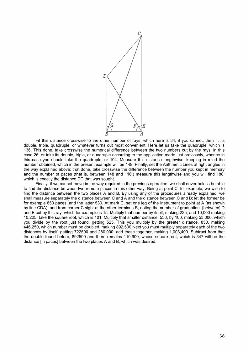
Fit this distance crosswise to the other number of rays, which here is 34; if you cannot, then fit its
double, triple, quadruple, or whatever turns out most convenient. Here let us take the quadruple, which is 136. This done, take crosswise the numerical difference between the two numbers cut by the rays, in this case 26, or take its double, triple, or quadruple according to the application made just previously, whence in this case you should take the quadruple, or 104. Measure this distance lengthwise, keeping in mind the number obtained, which in the present example will be 148. Finally, set the Arithmetic Lines at right angles in the way explained above; that done, take crosswise the difference between the number you kept in memory and the number of paces (that is, between 148 and 116;) measure this lengthwise and you will find 188, which is exactly the distance DC that was sought.
Finally, if we cannot move in the way required in the previous operation, we shall nevertheless be able to find the distance between two remote places in this other way. Being at point C, for example, we wish to find the distance between the two places A and B. By using any of the procedures already explained, we shall measure separately the distance between C and A and the distance between C and B; let the former be for example 850 paces, and the latter 530. At mark C, set one leg of the Instrument to point at A (as shown by line CDA), and from corner C sigh: at the other terminus B, noting the number of graduation [between] D and E cut by this ray, which for example is 15. Multiply that number by itself, making 225, and 10,000 making 10,225; take the square root, which is 101. Multiply that smaller distance, 530, by 100, making 53,000, which you divide by the root just found, getting 525. This you multiply by the greater distance, 850, making 446,250, which number must be doubled, making 892,500 Next you must multiply separately each of the two distances by itself, getting 722500 and 280,900; add these together, making 1,003,400. Subtract from that the double found before, 892500 and there remains 110,900, whose square root, which is 347 will be the distance [in paces] between the two places A and B, which was desired.
36
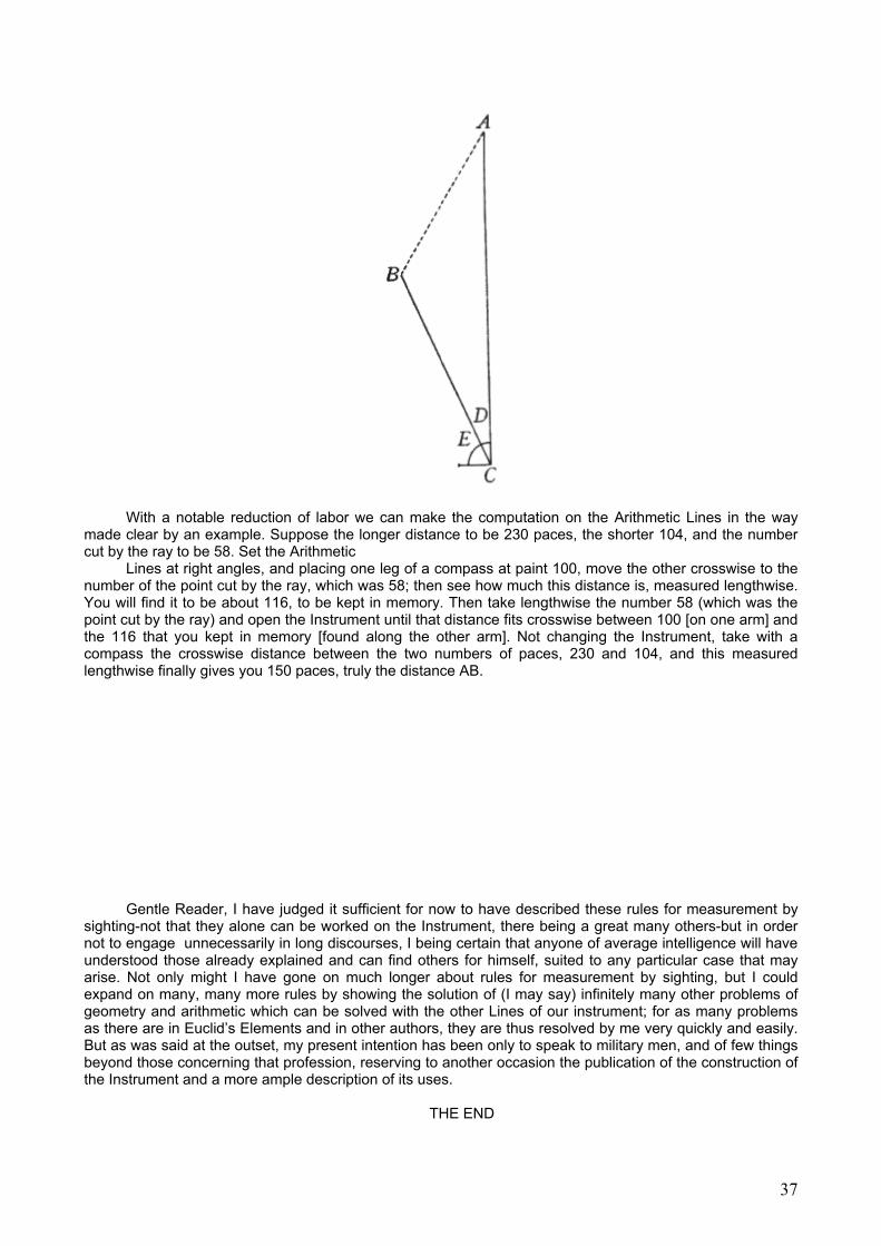
With a notable reduction of labor we can make the computation on the Arithmetic Lines in the way made clear by an example. Suppose the longer distance to be 230 paces, the shorter 104, and the number cut by the ray to be 58. Set the Arithmetic
Lines at right angles, and placing one leg of a compass at paint 100, move the other crosswise to the number of the point cut by the ray, which was 58; then see how much this distance is, measured lengthwise. You will find it to be about 116, to be kept in memory. Then take lengthwise the number 58 (which was the point cut by the ray) and open the Instrument until that distance fits crosswise between 100 [on one arm] and the 116 that you kept in memory [found along the other arm]. Not changing the Instrument, take with a compass the crosswise distance between the two numbers of paces, 230 and 104, and this measured lengthwise finally gives you 150 paces, truly the distance AB.
Gentle Reader, I have judged it sufficient for now to have described these rules for measurement by
sighting-not that they alone can be worked on the Instrument, there being a great many others-but in order not to engage unnecessarily in long discourses, I being certain that anyone of average intelligence will have understood those already explained and can find others for himself, suited to any particular case that may arise. Not only might I have gone on much longer about rules for measurement by sighting, but I could expand on many, many more rules by showing the solution of (I may say) infinitely many other problems of geometry and arithmetic which can be solved with the other Lines of our instrument; for as many problems as there are in Euclid’s Elements and in other authors, they are thus resolved by me very quickly and easily. But as was said at the outset, my present intention has been only to speak to military men, and of few things beyond those concerning that profession, reserving to another occasion the publication of the construction of the Instrument and a more ample description of its uses.
THE END
37