operations, service and parts manual · 8500 conveyor paver 8500 conveyor paver fm-1 this manual...
TRANSCRIPT

8500 Conveyor Paver
OPERATIONS, SERVICEAND PARTS MANUAL
8500 CONVEYOR PAVER
Manual No. 985682

8500 Conveyor Paver
688 North Highway 16Denver, North Carolina 28037
www.LeeBoy.com
LIMITED WARRANTYPOLICY AND PROCEDURES
EFFECTIVE FOR UNITS SHIPPED AFTER DECEMBER 1, 2001
WARRANTY
1. If a defect in material or workmanship isfound and the authorized dealer is notifiedduring the warranty period, LeeBoy willrepair or replace any part or component ofthe unit or part that fails to conform to thewarranty during the warranty period.
2. The warranty date will begin upon thecompletion of the warranty form by the initialcustomer and will expire after twelve (12)months have passed. The Warranty Cardshould be filled out within (10) days ofdelivery of the unit.
3. Engines are warranted by theirmanufacturers and may have warrantycoverage that differs from that of LeeBoy.
4. Replacement parts furnished by LeeBoy arecovered for the remainder of the warrantyperiod applicable to the unit or component inwhich such parts are installed.
5. LeeBoy has the right to repair anycomponent or part before replacing it with anew part.
6. All new replacement parts purchased by aLeeBoy dealer will carry a six (6) monthwarranty. Remanufactured parts purchasedby a LeeBoy dealer will carry a ninety (90)day warranty.
ITEMS NOT COVERED
LeeBoy is not responsible for the following:
1. Charges for travel time, mileage, orovertime.
2. Charges related to transporting the productto and from the place at which warrantywork is performed.
3. Airfreight charges related to transportingrepair parts to the place at which warrantywork is performed.
4. All used units or used parts of any kind.
5. Repairs due to normal wear and tear, orbrought about by abuse or lack ofmaintenance of the equipment, except forpremature failures, conveyor chains,polytrack pads, and track rails.
6. Attachments not manufactured or installed byLeeBoy.
7. Liability for incidental or consequentialdamages of any type including, but notlimited to lost profits or expenses of acquiringreplacement equipment.
8. Miscellaneous charges.
LIMITATIONS
LeeBoy has no obligation under this warranty for:
1. Any defects caused by misuse,misapplication, negligence, accident or failureto maintain or use in accordance with themost current operating instructions.
2. Unauthorized alterations.
3. Defects or failures caused by anyreplacement parts or attachments notmanufactured by or approved by LeeBoy.
4. Failure to conduct normal maintenance andoperating service, including without limitation,providing lubricants, coolant, fuel, tune-ups,inspections or adjustments.
5. Unreasonable delay, as established byLeeBoy, in making the applicable units orparts available upon notification of a servicenotice ordered by LeeBoy.
6. The warranty responsibility on all enginesrests with the respective manufacturer.
7. LeeBoy may have support agreements withsome engine manufacturers for warranty andparts support.
OTHER WARRANTIESTHE FOREGOING WARRANTY IS EXCLUSIVE AND INLIEU OF ALL OTHER EXPRESSED STATUTORY ANDIMPLIED WARRANTIES APPLICABLE TO UNITS ENGINES,OR PARTS WITHOUT LIMITATION, ALL IMPLIEDWARRANTIES OF MERCHANTABILITY OR FITNESS FORANY PARTICULAR USE OR PURPOSE. IN NO EVENT,WHETHER AS A RESULT OF BREACH OF CONTRACT ORWARRANTY, OR ALLEGED NEGLIGENCE OR LIABILITYWITHOUT FAULT, SHALL LEEBOY BE LIABLE FORSPECIAL, INCIDENTAL OR CONSEQUENTIAL DAMAGES,INCLUDING WITHOUT LIMITATION, LOSS OF PROFIT ORREVENUE, COST OF CAPITAL, COST OF SUBSTITUTEDEQUIPMENT, FACILITIES OR SERVICES DOWNTIMECOSTS, LABOR COSTS OR CLAIMS OF CUSTOMERS,PURCHASERS OR LESSEES FOR SUCH DAMAGES.

8500 CONVEYOR PAVER
8500 Conveyor Paver
DELIVERY DATE______________________________________
UNIT SERIAL NUMBER_________________________________
ENGINE TYPE________________________________________
ENGINE NUMBER_____________________________________
DEALER'S NAME AND ADDRESS
_____________________________________________________
_____________________________________________________
PHONE NUMBER_______________________________________
EQUIPMENT HOURS____________________________________
SERVICE MANAGER ____________________________________
688 North Highway 16 • Denver, North Carolina 28037 • www.LeeBoy.com • (704) 966-3300
USER'S REFERENCE GUIDE

8500 CONVEYOR PAVER
FM-18500 Conveyor Paver
This manual should be used with allrelated supplemental books, engine andtransmission manuals, and parts books.Related Service Bulletins should bereviewed to provide information regardingsome of the recent changes.
If any questions arise concerning thispublication or others, contact your localLeeBoy Distributor for the latest availableinformation.
Contents of this manual are based oninformation in effect at the time ofpublication and are subject to changewithout notice.
MODEL 8500 CONVEYOR PAVEROPERATORS, MAINTENANCE AND PARTS MANUAL
REAR VIEW
SIDE VIEW

8500 CONVEYOR PAVER
FM-2 8500 Conveyor Paver
DANGERYOU MUST FOLLOW ALL DANGER SAFETYNOTES. IF YOU DO NOT FOLLOW THEINSTRUCTIONS, YOUR MISTAKE MIGHT LIKELYRESULT IN VERY SERIOUS INJURY OR DEATH.
WARNINGWARNING safety notes must ALSO be followed.Your mistake might result in SERIOUS INJURY toyourself or others.
CAUTIONCAUTION safety notes are ALSO very important.They point out to you where your mistakes couldcause PHYSICAL HARM to you or others, ordamage to the machine.
This manual provides importantinformation to familiarize you with safeoperating and maintenance procedures.Even though you may be familiar withsimilar equipment, you MUST read andunderstand this manual before operatingthis unit.
Safety is everyone's business and is oneof your primary concerns. Knowing theguidelines covered in the followingparagraphs and in Section 1 will help
provide for your safety, for the safety ofthose around you, and for the paver'sproper operation.
LOOK FOR THESE SYMBOLS WHICHPOINT OUT ITEMS OF EXTREMEIMPORTANCE TO YOU AND YOURCOWORKERS SAFETY. READ ANDUNDERSTAND THOROUGHLY. HEEDTHE WARNING AND FOLLOW THEINSTRUCTIONS.
IIMMPPOORRTTAANNTT
SAFETY INSTRUCTIONS

8500 CONVEYOR PAVER
FM-38500 Conveyor Paver
SAFETY PRECAUTIONSIf your paver has been repainted, it isextremely important that all the decalsreferring to cautions warnings and dangerbe replaced in their proper locations. Theillustrations on this page will aid you indetermining the proper locations. Howeverfor additional help, you should refer to theparts listing in the parts section of thismanual and note the description column.
Under this column a description onlocation is provided for each decal. If youstill need more explicit instructions, contactyour dealer.
NOTEIt is the responsibility of the owner andoperator to make sure that all decalsare readable and located on paver asdesignated by the manufacturer.
8500 DECALS and DECAL LOCATIONS

8500 CONVEYOR PAVER
FM-4 8500 Conveyor Paver
PRE-START INSPECTIONINSPECT machine. Have any malfunctioning,broken or missing parts corrected or replacedbefore using. Hydraulic hoses should be checkeddaily for wear and leaks. Replace if damaged.
CHECK that all the instruction and safety labels arein place and readable. These are as important asany other equipment on the machine.
READ and FOLLOW all instruction decals.
WEAR OSHA required safety equipment whenrunning the paver.
FILL the fuel tank with the engine off. Never fill fueltank near an open flame, when smoking, or whenscreed heat is on.
CLEAR auger & feeders before starting engine.Make sure all covers and guards are in place.
OPERATING SAFETYALWAYS make sure no person or object is in yourline of travel BEFORE starting.
WORK slowly in tight areas.
DO NOT run engine in a closed building for longperiods of time. NEVER spray cleaning solvent orrelease agent on or near screed while it is beingheated.
AVOID steep hills if possible.
ALWAYS look BEFORE changing your direction oftravel.
NEVER open a valve to burner unless a flame ispresent. Heat screed for no more than 15 minutes.Make sure all valves are closed before propane isturned off.
AVOID leaving engine running without operatorpresent.
STOPPING SAFETYALWAYS park the paver on solid, level ground inlow range. If this is not possible, always park thepaver at a right angle to the slope. Lower screedwhen parked.
USE proper flags, barriers and warning devicesespecially when parking in areas of traffic.
MAINTENANCE SAFETYNEVER work on the paver with the engine running.
NEVER fill the fuel tank with the engine running.DO NOT change the engine governor settings.ALWAYS replace damaged or lost decals.DISCONNECT battery cables when working on theelectrical system or when welding on the unit.
IF battery needs a charge, be sure battery chargeris off when making connections.
BE SURE the correct battery polarity is observed(negative (-) to negative (-) and positive (+) topositive (+), when connecting a battery charger orjumper cable.
DANGERNEVER WORK UNDER HOPPER WITHOUTPLACING SAFETY PROP IN POSITION. SEEFIGURE 1.
FIGURE 1. SAFETY PROP

8500 Conveyor Paver
Section 1INTRODUCTION
1-1
TABLE OF CONTENTSPage
GENERAL INFORMATION . . . . . . . . . . . . . . . . . . . . . . . . . . . . . . . . . . . . . . . . . . . . . . . . . . . . . . . . . .1-2
SPECIFICATIONS . . . . . . . . . . . . . . . . . . . . . . . . . . . . . . . . . . . . . . . . . . . . . . . . . . . . . . . . . . . . . . . . .1-2
CONTROLS AND OPERATING INSTRUCTIONS . . . . . . . . . . . . . . . . . . . . . . . . . . . . . . . . . . . . . . . . .1-2
MAINTENANCE PROCEDURES . . . . . . . . . . . . . . . . . . . . . . . . . . . . . . . . . . . . . . . . . . . . . . . . . . . . . .1-2
NAMEPLATE . . . . . . . . . . . . . . . . . . . . . . . . . . . . . . . . . . . . . . . . . . . . . . . . . . . . . . . . . . . . . . . . . . . . .1-2

Section 1INTRODUCTION
1-2 8500 Conveyor Paver
GENERAL INFORMATIONThis manual contains Specification information,Controls and Operating Procedures, Maintenanceand Repair Procedures and Parts Lists for the8500 Conveyor Paver.
SPECIFICATIONSRefer to Section 2 - SPECIFICATIONS in thismanual for all major system specifications and fortypical torque value tables.
CONTROLS AND OPERATINGINSTRUCTIONSRefer to Section 3 - OPERATION.
The operator of this equipment should READ,UNDERSTAND, and FOLLOW the operatinginstructions, Cautions, and Warnings provided inthe front of this manual and in the OPERATIONsection.
WARNING: Do not attempt to operate the 8500Conveyor Paver unless fullytrained in the machine operation,only authorized personnel shouldoperate the Model 8500 ConveyorPaver. All instructions provided inthis manual and on the machineoperating and warning decals mustbe followed to prevent damage tothe equipment and/or injury tooperating personnel.
MAINTENANCE PROCEDURESRefer to Section 4 - MAINTENANCE in this manualfor all maintenance and repair procedures.
CAUTION: All maintenance instructionsprovided in this manual should befollowed to insure safety of thepersonnel performing themaintenance and to preventdamage to the machine.
NAMEPLATEThe nameplate contains the serial number andbasic data used to identify the specific model onthe conveyor paver (see Figure 1-1).
FIGURE 1-1. NAME PLATE

8500 Conveyor Paver
Section 2SPECIFICATIONS
2-1
TABLE OF CONTENTSPage
GENERAL INFORMATION . . . . . . . . . . . . . . . . . . . . . . . . . . . . . . . . . . . . . . . . . . . . . . . . . . . . . . . . . . 2-2
TABLE 2-1. ENGINE SPECIFICATIONS . . . . . . . . . . . . . . . . . . . . . . . . . . . . . . . . . . . . . . . . . . . . . . . . 2-2
TABLE 2-2. ELECTRICAL SPECIFICATIONS. . . . . . . . . . . . . . . . . . . . . . . . . . . . . . . . . . . . . . . . . . . . 2-2
TABLE 2-3. DIMENSION SPECIFICATIONS . . . . . . . . . . . . . . . . . . . . . . . . . . . . . . . . . . . . . . . . . . . . 2-3
TABLE 2-4. PERFORMANCE SPECIFICATIONS. . . . . . . . . . . . . . . . . . . . . . . . . . . . . . . . . . . . . . . . . 2-3
TABLE 2-5. MACHINE SYSTEM CAPACITY SPECIFICATIONS. . . . . . . . . . . . . . . . . . . . . . . . . . . . . 2-4
TABLE 2-6. MACHINE HYDRAULIC PRESSURES. . . . . . . . . . . . . . . . . . . . . . . . . . . . . . . . . . . . . . . . 2-4
TABLE 2-7. TYPES OF LUBRICANTS. . . . . . . . . . . . . . . . . . . . . . . . . . . . . . . . . . . . . . . . . . . . . . . . . 2-4
TABLE 2-8. TORQUE SPECIFICATIONS FOR STANDARD INCH FASTENERS. . . . . . . . . . . . . . . . . 2-5
TABLE 2-9. TORQUE SPECIFICATIONS FOR METRIC FASTENERS . . . . . . . . . . . . . . . . . . . . . . . . 2-6

8500 Conveyor Paver
Section 2SPECIFICATIONS
2-2
TABLE 2-1. ENGINE SPECIFICATIONS
ITEM CHARACTERISTIC
ENGINE
Model and Manufacturer . . . . . . . . . . . . . .Hatz, 4L41C (Silent Pak)
Type . . . . . . . . . . . . . . . . . . . . . . . . . . . . . .4 Cycle diesel
Number of Cylinders . . . . . . . . . . . . . . . . .Four
Bore & Stroke . . . . . . . . . . . . . . . . . . . . . .4.02 in. [102 mm] x 4.13 in. [105 mm]
Engine Oil Type . . . . . . . . . . . . . . . . . . . .10W-40
Capacity . . . . . . . . . . . . . . . . . . . . . . . . . .12 Quarts [11.3 liter]
ENGINE COOLING SYSTEM
Type . . . . . . . . . . . . . . . . . . . . . . . . . . . . . .Air Cooled
ENGINE FUEL
Type Used . . . . . . . . . . . . . . . . . . . . . . . . .Diesel Fuel
Fuel Capacity . . . . . . . . . . . . . . . . . . . . . .20 gallons [75.7 liters]
FUEL FILTER
Type . . . . . . . . . . . . . . . . . . . . . . . . . . . . . .Hatz Diesel
FUEL INJECTORS
Quantity and Type . . . . . . . . . . . . . . . . . . .Four, close nozzle
TABLE 2-2. ELECTRICAL SPECIFICATIONS
ITEM CHARACTERISTIC
BATTERY
Number Per Machine . . . . . . . . . . . . . . . .One maintenance free
Ampere Hour Rating . . . . . . . . . . . . . . . . .680 CCA
Voltage . . . . . . . . . . . . . . . . . . . . . . . . . . .12 Volts
ALTERNATOR
Type and Voltage . . . . . . . . . . . . . . . . . . . .Valeo, 12 Volt, negative ground
Output Amperage . . . . . . . . . . . . . . . . . . .50 Amps
Fan Belt Tension . . . . . . . . . . . . . . . . . . .Automatic belt tension mechanism keepsserpentine belt under tension at all times
STARTER
Manufacturer . . . . . . . . . . . . . . . . . . . . . . .(See Engine Starter plate)
Voltage and Type . . . . . . . . . . . . . . . . . . . .12 Volt, negative ground
Rating . . . . . . . . . . . . . . . . . . . . . . . . . . . .2.7 kW
GENERAL INFORMATIONThe specifications provided in this section are applicable to the Model 8500 Conveyor Paver. Included in thissection are machine weights, dimensions, performance and torque values for both metric and standard inchfasteners.

8500 Conveyor Paver
Section 2SPECIFICATIONS
2-3
TABLE 2-3. DIMENSION SPECIFICATIONS (see Figure 2-1)
ITEM SPECIFICATION
DIMENSIONS
Overall Length “A” . . . . . . . . . . . . . . . . . . .12′ 4″ (365 cm)
Overall Height . . . . . . . . . . . . . . . . . . . . . .6′ 6″ (198 cm)
Overall Width (hopper wings in) . . . . . . . .8′ 6″ (259 cm)
Overall Width (hopper wings out) . . . . . . .10′ (305 cm)
Weight . . . . . . . . . . . . . . . . . . . . . . . . . . . .15,600 lbs (7076 kg)
FIGURE 2-1. OUTLINE DIMENSIONAL DRAWING
TABLE 2-4. PERFORMANCE SPECIFICATIONS
ITEM SPECIFICATION
SPEED
Travel . . . . . . . . . . . . . . . . . . . . . . . . . . . . .240 FPM (0.73 KPM)
Paving . . . . . . . . . . . . . . . . . . . . . . . . . . . .140 FPM (0.366 KPM)
EFFECTIVE COVERAGE
Basic Screed Width . . . . . . . . . . . . . . . . . .8 ft. (2.44 m)
Maximum Screed Width . . . . . . . . . . . . . .15 ft. (4.57 m)

8500 Conveyor Paver
Section 2SPECIFICATIONS
2-4
TABLE 2-5. MACHINE SYSTEM CAPACITY SPECIFICATIONS
ITEM SPECIFICATION
SYSTEM CAPACITIES
Fuel . . . . . . . . . . . . . . . . . . . . . . . . . . . . . .20 gallons [75.7 liters]
Engine Lubrication Oil . . . . . . . . . . . . . . .12 quarts [11.35 liters] (with lubrication oil filter)
Hydraulic Oil Reservoir . . . . . . . . . . . . . . .40 gallons [151.4 liters]
Torque Hubs . . . . . . . . . . . . . . . . . . . . . . .32 ounces [0.355 liters] each
TABLE 2-6. MACHINE HYDRAUIC PRESSURES
ITEM SPECIFICATION
Drive . . . . . . . . . . . . . . . . . . . . . . . . . . . . .3000 PSI (207 Bar)
Conveyors . . . . . . . . . . . . . . . . . . . . . . . . .2400 PSI (165 Bar)
Augers & Cylinders . . . . . . . . . . . . . . . . . .2000 PSI (138 Bar)
TABLE 2-7. TYPES OF LUBRICANTS
ITEM SPECIFICATION
Engine Oil . . . . . . . . . . . . . . . . . . . . . . . . .10W-40
Hydraulic Oil . . . . . . . . . . . . . . . . . . . . . . .AW #68 or 5W20 AWAT (All weather alltemperature)
Torque Hub Grease . . . . . . . . . . . . . . . . . .90 WT Gear Lub
Grease . . . . . . . . . . . . . . . . . . . . . . . . . . .Shell Avania EP Grease or Equivalent
Chain Lub . . . . . . . . . . . . . . . . . . . . . . . . .Chain Lub

8500 Conveyor Paver
Section 2SPECIFICATIONS
2-5
WARNING: The following Table lists torque values for standard hardware and are intended as aguide for average application involving typical stresses and machined surfaces. Valuesare based on physical limitations of clean, plated and lubricated hardware. In all cases,when an individual torque value is specified, it should be followed instead of valuesgiven in this table.
CAUTION: Replace original equipment with hardware of equal grade.
TABLE 2-8. TORQUE SPECIFICATIONS FOR STANDARD INCH FASTENERS
CAPSCREWS: SAE GRADE 5 CAPSCREWS: SAE GRADE 8
SIZE THREAD TORQUE FT. LBS. TORQUE N•m TORQUE FT. LBS. TORQUE N•m
Dry Lubed Dry Lubed Dry Lubed Dry Lubed
1/4 20 UNC 8 6 11 9 12 9 16 12
28 UNF 10 7 13 10 14 10 19 14
5/16 18 UNC 17 13 24 18 25 18 33 25
24 UNF 19 14 26 20 27 20 37 28
3/8 16 UNC 31 23 42 31 44 33 59 44
24 UNF 35 26 47 36 49 37 67 50
7/16 14 UNC 49 37 67 50 70 52 95 71
20 UNF 55 41 75 56 78 58 105 79
1/2 13 UNC 75 57 100 77 105 80 145 110
20 UNF 85 64 115 86 120 90 165 120
9/16 12 UNC 110 82 145 110 155 115 210 155
18 UNF 120 91 165 125 170 130 230 175
5/8 11 UNC 150 115 205 155 210 160 285 215
18 UNF 170 130 230 175 240 180 325 245
3/4 10 UNC 265 200 360 270 375 280 510 380
16 UNF 295 225 405 300 420 315 570 425
7/8 9 UNC 430 320 580 435 605 455 820 615
14 UNF 475 355 640 480 670 500 905 680
1 8 UNC 645 485 875 655 910 680 1230 925
14 NF 720 540 980 735 1020 765 1380 1040
1-1/8 7 UNC 795 595 1080 805 1290 965 1750 1310
12 UNF 890 670 1210 905 1440 1080 1960 1470
1-1/4 7 UNC 1120 840 1520 1140 1820 1360 2460 1850
12 UNF 1240 930 1680 1260 2010 1500 2730 2050
1-3/8 6 UNC 1470 1100 1990 1490 2380 1780 3230 2420
12 UNF 1670 1250 2270 1700 2710 2040 3680 2760
1-1/2 6 UNC 1950 1460 2640 1980 3160 2370 4290 3210
12 UNF 2190 1650 2970 2230 3560 2670 4820 3620

8500 Conveyor Paver
Section 2SPECIFICATIONS
2-6
WARNING: The following Table lists torque values for standard hardware and are intended as aguide for average application involving typical stresses and machined surfaces. Valuesare based on physical limitations of clean, plated and lubricated hardware. In all cases,when an individual torque value is specified, it should be followed instead of valuesgiven in this table.
CAUTION: Replace original equipment with hardware of equal grade.
TABLE 2-9. TORQUE SPECIFICATIONS FOR METRIC FASTENERS
NOMINAL SIZE CLASS 8.8 CLASS 10.9 & PITCH [GRADE 5 EQUIVALENT] [GRADE 8 EQUIVALENT]
TORQUE FT. LBS. TORQUE N•m TORQUE FT. LBS. TORQUE N•m
Dry Lubed Dry Lubed Dry Lubed Dry Lubed
M4 x 0.7 2.27 1.70 3.07 2.30 2.27 2.31 4.17 3.13
M5 x 0.8 4.58 3.43 6.20 4.65 6.22 4.67 8.43 6.33
M6 x 1 7.75 5.83 10.5 7.90 10.60 7.97 14.3 10.8
M8 x 1.25 18.89 14.17 25.6 19.2 18.95 19.26 34.8 26.1
M10 x 1.25 39.11 29.52 53.0 40.1 53.87 40.59 73.0 55.0
M12 x 1.75 64.94 48.71 88.0 66.0 88.56 66.42 120.0 90.0
M14 x 2 103.32 77.49 140.0 105.0 140.22 107.01 190.0 145.0
M16 x 2 162.36 121.77 220.0 165.0 221.40 166.05 300.0 225.0
M20 x 2.5 317.34 236.16 430.0 320.0 428.04 321.03 580.0 435.0
M24 x 3 516.12 409.59 740.0 555.0 754.38 557.19 1010.0 755.0
M27 x 3 797.04 597.78 1080.0 810.0 1084.86 811.80 1470.0 1100.0
M30 x 3.5 1084.86 811.80 1470.0 1100.0 1476.00 1107.00 2000.0 1500.0

8500 Conveyor Paver
Section 3OPERATION
3-1
TABLE OF CONTENTSPage
GENERAL INFORMATION . . . . . . . . . . . . . . . . . . . . . . . . . . . . . . . . . . . . . . . . . . . . . . . . . . . . . . . . . .3-3
OPERATING CONTROLS, INDICATORS, AND GAUGES . . . . . . . . . . . . . . . . . . . . . . . . . . . . . . . . . .3-3
OPERATION . . . . . . . . . . . . . . . . . . . . . . . . . . . . . . . . . . . . . . . . . . . . . . . . . . . . . . . . . . . . . . . . . . . .3-18
SAFETY . . . . . . . . . . . . . . . . . . . . . . . . . . . . . . . . . . . . . . . . . . . . . . . . . . . . . . . . . . . . . . . . . . . . . .3-18
Operating Safety . . . . . . . . . . . . . . . . . . . . . . . . . . . . . . . . . . . . . . . . . . . . . . . . . . . . . . . . . . . . . .3-18
Stopping Safety . . . . . . . . . . . . . . . . . . . . . . . . . . . . . . . . . . . . . . . . . . . . . . . . . . . . . . . . . . . . . .3-18
Maintenance Safety . . . . . . . . . . . . . . . . . . . . . . . . . . . . . . . . . . . . . . . . . . . . . . . . . . . . . . . . . . .3-18
PRE-START INSPECTION . . . . . . . . . . . . . . . . . . . . . . . . . . . . . . . . . . . . . . . . . . . . . . . . . . . . . . . .3-18
STARTING THE ENGINE . . . . . . . . . . . . . . . . . . . . . . . . . . . . . . . . . . . . . . . . . . . . . . . . . . . . . . . . .3-18
Preliminary . . . . . . . . . . . . . . . . . . . . . . . . . . . . . . . . . . . . . . . . . . . . . . . . . . . . . . . . . . . . . . . . . .3-18
Engine Start-up . . . . . . . . . . . . . . . . . . . . . . . . . . . . . . . . . . . . . . . . . . . . . . . . . . . . . . . . . . . . . . .3-19
Stopping the Engine . . . . . . . . . . . . . . . . . . . . . . . . . . . . . . . . . . . . . . . . . . . . . . . . . . . . . . . . . . .3-19
Engine Start-up (With Optional Steering Box) . . . . . . . . . . . . . . . . . . . . . . . . . . . . . . . . . . . . . . .3-19
Stopping the Engine (With Optional Steering Box) . . . . . . . . . . . . . . . . . . . . . . . . . . . . . . . . . . .3-20
PAVER DRIVING INSTRUCTIONS . . . . . . . . . . . . . . . . . . . . . . . . . . . . . . . . . . . . . . . . . . . . . . . . .3-20
General Control Information . . . . . . . . . . . . . . . . . . . . . . . . . . . . . . . . . . . . . . . . . . . . . . . . . . . . .3-20
Operating Information . . . . . . . . . . . . . . . . . . . . . . . . . . . . . . . . . . . . . . . . . . . . . . . . . . . . . . . . . .3-20
PAVER DRIVING INSTRUCTIONS (With Optional Steering Box) . . . . . . . . . . . . . . . . . . . . . . . . . .3-20
General . . . . . . . . . . . . . . . . . . . . . . . . . . . . . . . . . . . . . . . . . . . . . . . . . . . . . . . . . . . . . . . . . . . .3-20
The Electronic Control Steering Box . . . . . . . . . . . . . . . . . . . . . . . . . . . . . . . . . . . . . . . . . . . .3-20
PAVER PREPARATION INSTRUCTIONS . . . . . . . . . . . . . . . . . . . . . . . . . . . . . . . . . . . . . . . . . . . .3-21
Burner Ignition Procedures . . . . . . . . . . . . . . . . . . . . . . . . . . . . . . . . . . . . . . . . . . . . . . . . . . . . . .3-21
General . . . . . . . . . . . . . . . . . . . . . . . . . . . . . . . . . . . . . . . . . . . . . . . . . . . . . . . . . . . . . . . . . . .3-21
Manual Lighting of Burners . . . . . . . . . . . . . . . . . . . . . . . . . . . . . . . . . . . . . . . . . . . . . . . . . . .3-22
TRUCK HITCH ATTACHMENT (OPTIONAL) . . . . . . . . . . . . . . . . . . . . . . . . . . . . . . . . . . . . . . . . . . .3-22
GENERAL . . . . . . . . . . . . . . . . . . . . . . . . . . . . . . . . . . . . . . . . . . . . . . . . . . . . . . . . . . . . . . . . . . . .3-22
OPERATING FEEDER . . . . . . . . . . . . . . . . . . . . . . . . . . . . . . . . . . . . . . . . . . . . . . . . . . . . . . . . . . . . .3-23
GENERAL . . . . . . . . . . . . . . . . . . . . . . . . . . . . . . . . . . . . . . . . . . . . . . . . . . . . . . . . . . . . . . . . . . . .3-23
OPERATING ELECTRIC FLIGHT SCREWS . . . . . . . . . . . . . . . . . . . . . . . . . . . . . . . . . . . . . . . . . . . .3-24
GENERAL . . . . . . . . . . . . . . . . . . . . . . . . . . . . . . . . . . . . . . . . . . . . . . . . . . . . . . . . . . . . . . . . . . . . .3-24
OPERATING HYDRAULIC CUTOFF GATES . . . . . . . . . . . . . . . . . . . . . . . . . . . . . . . . . . . . . . . . . . .3-24
GENERAL . . . . . . . . . . . . . . . . . . . . . . . . . . . . . . . . . . . . . . . . . . . . . . . . . . . . . . . . . . . . . . . . . . . .3-24
ELECTRIC SPRAY DOWN . . . . . . . . . . . . . . . . . . . . . . . . . . . . . . . . . . . . . . . . . . . . . . . . . . . . . . . . .3-25
GENERAL . . . . . . . . . . . . . . . . . . . . . . . . . . . . . . . . . . . . . . . . . . . . . . . . . . . . . . . . . . . . . . . . . . . .3-25
AUGERS . . . . . . . . . . . . . . . . . . . . . . . . . . . . . . . . . . . . . . . . . . . . . . . . . . . . . . . . . . . . . . . . . . . . . . .3-25
AUGER EXTENSIONS . . . . . . . . . . . . . . . . . . . . . . . . . . . . . . . . . . . . . . . . . . . . . . . . . . . . . . . . . . .3-25
SONIC AUGERS . . . . . . . . . . . . . . . . . . . . . . . . . . . . . . . . . . . . . . . . . . . . . . . . . . . . . . . . . . . . . . .3-26
General . . . . . . . . . . . . . . . . . . . . . . . . . . . . . . . . . . . . . . . . . . . . . . . . . . . . . . . . . . . . . . . . . . . . .3-26
Operating Augers . . . . . . . . . . . . . . . . . . . . . . . . . . . . . . . . . . . . . . . . . . . . . . . . . . . . . . . . . . . . .3-26

Section 3OPERATION
3-2 8500 Conveyor Paver
TABLE OF CONTENTSPage
LOADING AND UNLOADING . . . . . . . . . . . . . . . . . . . . . . . . . . . . . . . . . . . . . . . . . . . . . . . . . . . . . . .3-27
GENERAL . . . . . . . . . . . . . . . . . . . . . . . . . . . . . . . . . . . . . . . . . . . . . . . . . . . . . . . . . . . . . . . . . . . . .3-27
UNLOADING . . . . . . . . . . . . . . . . . . . . . . . . . . . . . . . . . . . . . . . . . . . . . . . . . . . . . . . . . . . . . . . . . .3-27
LOADING . . . . . . . . . . . . . . . . . . . . . . . . . . . . . . . . . . . . . . . . . . . . . . . . . . . . . . . . . . . . . . . . . . . . .3-28
TIE DOWN PROCEDURE . . . . . . . . . . . . . . . . . . . . . . . . . . . . . . . . . . . . . . . . . . . . . . . . . . . . . . . . . .3-29
PAVING PREPARATION INSTRUCTIONS . . . . . . . . . . . . . . . . . . . . . . . . . . . . . . . . . . . . . . . . . . . . .3-29
STARTING TO PAVE . . . . . . . . . . . . . . . . . . . . . . . . . . . . . . . . . . . . . . . . . . . . . . . . . . . . . . . . . . . . . .3-30
GENERAL . . . . . . . . . . . . . . . . . . . . . . . . . . . . . . . . . . . . . . . . . . . . . . . . . . . . . . . . . . . . . . . . . . . .3-30
SETTING SCREED TO PAVE . . . . . . . . . . . . . . . . . . . . . . . . . . . . . . . . . . . . . . . . . . . . . . . . . . . . .3-31
SETTING SCREED ENDGATES . . . . . . . . . . . . . . . . . . . . . . . . . . . . . . . . . . . . . . . . . . . . . . . . . . .3-33
SETTING SCREED EXTENSIONS (Used when paving over 8 ft. [2.4 m]) . . . . . . . . . . . . . . . . . . .3-33
PAVER OPERATION . . . . . . . . . . . . . . . . . . . . . . . . . . . . . . . . . . . . . . . . . . . . . . . . . . . . . . . . . . . .3-34

Section 3OPERATION
3-38500 Conveyor Paver
GENERAL INFORMATIONThis section provides the Operating Instructions forthe Model 8500 Conveyor Paver.
It is important to read, understand, and follow all"Precautions Operating Instructions and Warnings"written in this manual before starting or operatingthe machine.
DANGER: FAILURE TO OBSERVE THE“OPERATING PRECAUTIONS AND WARNING INSTRUCTIONS”PROVIDED IN THIS MANUAL CANCAUSE SERIOUS INJURY ORDEATH. ONLY AUTHORIZED PERSONNEL, WHO ARE FULLYTRAINED IN THE MACHINE OPERATION, CAN OPERATE THEMODEL 8500 CONVEYOR PAVER.
This machine should be kept in good mechanicalcondition at all times.
WARNING: Do not operate a machine needingrepair. Put an information tag onthe instrument panel that says,“DO NOT OPERATE”. Remove thekey from the ignition switch.Repair all damage at once. Minordamage can result in major systemfailures.
OPERATING CONTROLS, INDICATORS,AND GAUGESOperating controls for the Model 8500 ConveyorPaver are shown in Figures 3-1 through 3-5 andlisted in Tables 3-1 through 3-5.
WARNING: Do not start or operate the Model8500 Conveyor Paver before read-ing, understanding and followingall information given in this sectionand shown on the machine. Theoperators must read and under-stand the function of all controls,indicators, and gauges beforestarting the engine. Serious injuryor death can result if these proce-dures are not followed.

Section 3OPERATION
3-4 8500 Conveyor Paver
FIGURE 3-1. LOCATION OF OPERATION PANELS AND CONTROLS
TABLE 3-1. LOCATION OF OPERATION PANELS AND CONTROLS
FIG. REF ITEM NO. CONTROL NAME TYPE FUNCTION
3-1 1 Instrument (dash) Contains switches, indicators, andPanel gauges (see Figure 3-2).
3-1 2 Left Burner Control Controls flow of propane to left screed burner.
3-1 3 Right Burner Control Controls flow of propane to rightscreed burner.
3-1 4 Steering and Speed Handles control the Control Module Steering and Speed Control
(see Figure 3-3).
3-1 5 Hydraulic Controls Contains the hydraulic controls that operate the Screed and other Functions (see Figure 3-4).

Section 3OPERATION
3-58500 Conveyor Paver
FIGURE 3-2. MAIN DASH PANEL CONTROLS, INDICATORS, AND GAUGES (Sheet 1 of 3)

Section 3OPERATION
3-6 8500 Conveyor Paver
FIGURE 3-2. MAIN DASH PANEL CONTROLS, INDICATORS, AND GAUGES (Sheet 2 of 3)
Section 3OPERATION
3-78500 Conveyor Paver
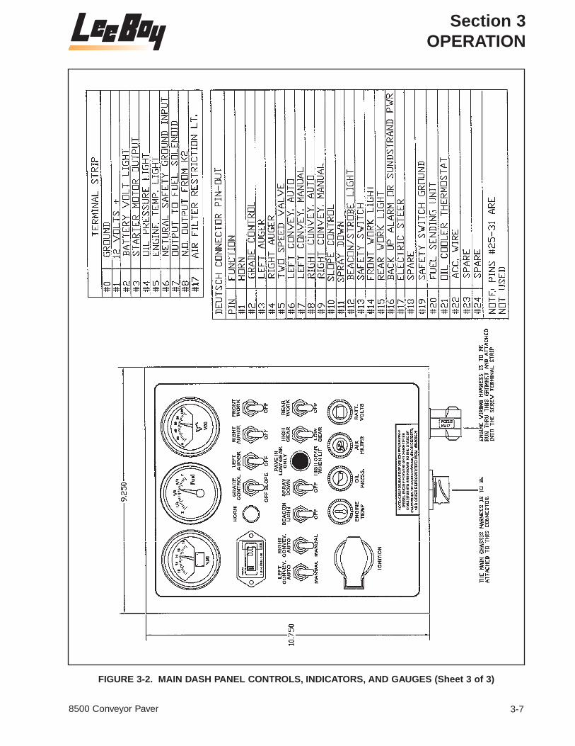
FIGURE 3-2. MAIN DASH PANEL CONTROLS, INDICATORS, AND GAUGES (Sheet 3 of 3)

Section 3OPERATION
3-8 8500 Conveyor Paver
3-2 1 Voltmeter Indicates battery voltage.
3-2 2 Fuel Gauge Indicates amount of fuel in fuel tank.
3-2 3 Oil Pressure Gauge Indicates the amount of oil pressure.
3-2 4 Hourmeter Meter monitors the working hours of the machine.
3-2 5 HORN Switch Push button Press button to sound the horn.switch
3-2 6 GRADE CONTROL 2-Position toggle When switch is in the GRADE GRADE/SLOPE switch position, power is ON all the time.Switch
NOTE: When machine is equipped with slope, power is present only when the joystick is in the FORWARD position.In the NEUTRAL position of the GRADE SLOPE switch, all power is turned off.
3-2 7 LEFT SONIC 2-Position toggle Selects ON or OFF for the automaticAUGER Switch switch operation of left auger.
Auto: Top position turns ON the Left Auger.
Auto: Bottom position turns OFF the Left Auger.
3-2 8 RIGHT SONIC 2-Position toggle Selects ON or OFF for the automaticAUGER Switch switch operation of right auger.
Auto: Top position turns ON the Right Auger.
Auto: Bottom position turns OFF the Right Auger.
3-2 9 FRONT WORK 2-Position toggle Used to turn the work lightsLIGHTS Switch switch on or off.
3-2 10 LEFT CONVEYOR 3-Position Selects automatic or manualAUTOMATIC/ automatic center override for left conveyor.MANUAL Switch return from
MANUAL position Center is OFF position.
For automatic operation set switch to AUTOMATIC position.
MANUAL position provides override.
FIG. REF ITEM NO. CONTROL NAME TYPE FUNCTION
TABLE 3-2. OPERATING CONTROLS, INDICATORS, AND GAUGES

Section 3OPERATION
3-98500 Conveyor Paver
3-2 11 RIGHT CONVEYOR 3-Position Selects automatic or manual AUTOMATIC/ automatic center override for right conveyor.MANUAL Switch return from
MANUAL position Center is OFF position.
For automatic operation set switch to AUTOMATIC position.
MANUAL position provides override.
3-2 12 BEACON Switch 2-Position toggle Used to turn the beacon light switch on or off.
Set switch to BEACON position to turn the Beacon light on.
3-2 13 SPRAY DOWN 2-Position toggle Used to turn on the Spray Down Switch switch System.
Set switch to SPRAY DOWN position to turn spray system on.
3-2 14 2-SPEED Light Illuminates to indicate when 2-SPEED HIGH/LOW switch is in the HIGH position.
3-2 15 2-SPEED HIGH/LOW 2-Position toggle Used to change machine speed.Switch switch
Place switch in HIGH position for travel. (When in TRAVEL red 2-SPEED Light (Item 14) will illuminate.)
IMPORTANT: High speed is only for traveling. Never pave in high speed.
3-2 16 REAR WORK 2-Position toggle Used to turn the rear work lights LIGHTS Switch switch ON or OFF.
FIG. REF ITEM NO. CONTROL NAME TYPE FUNCTION
TABLE 3-2. OPERATING CONTROLS, INDICATORS, AND GAUGES (CONTINUED)

Section 3OPERATION
3-10 8500 Conveyor Paver
3-2 17 Ignition Switch Key operated Controls starting, stopping, and Rotary 3-position running of engine.Switch
Vertical position is OFF. Turn right one notch for power. Red light will illuminate until engine cranks.
Far right is the START position.After engine starts release switch, which will automatically return to the power position.
Use protective cover when not in use.
NOTE: Engine will not start unless speed control is in NEUTRAL.
3-2 18 Engine Temperature Indicates engine temperature.Gauge
3-2 19 Oil Pressure Guage Indicates Low Oil Pressure.
3-2 20 Dirty Air Cleaner Light illuminates to indicate if air Indicator cleaner needs to be cleaned or
replaced.
3-2 21 Battery Indicator Light indicates if the unit is charging.Light
NOTE: If working properly, the light illuminates with the switch, and goes out when the engine cranks. If battery indicator light does not illuminate with key ON, the unit will not charge.
FIG. REF ITEM NO. CONTROL NAME TYPE FUNCTION
TABLE 3-2. OPERATING CONTROLS, INDICATORS, AND GAUGES (CONTINUED)

Section 3OPERATION
3-118500 Conveyor Paver
3-3 1 Left Steering Lever controls the speed and Handle direction of the left side of the
paver. Lever controls travel forward and reverse, and rate of travel.
Moving lever forward moves left side of machine forward. The further forward the higher the speed.
Moving lever backward moves the left side of machine backward. The further backward the higher the speed.
3-3 2 Right Steering Lever controls the speed and Handle direction of the right side of the
paver. Lever controls travel forward and reverse, and rate of travel.
Moving lever forward moves right side of machine forward. Thefurther forward the higher the speed.
Moving lever backward moves the right side of machine backward.The further backward the higher the speed.
3-3 3 Neutral Lock Locks the levers in neutral and work neutral safety switch for cranking engine.
3-3 4 Neutral Pause 2-Position toggle Applys neutral pause switch.Switch switch Making neutral band wider
between forward and reverse.
3-3 5 Light Red light Burns when the neutral pause is on.
FIGURE 3-3. STEERING AND SPEED CONTROL MODULE
FIG. REF ITEM NO. CONTROL NAME TYPE FUNCTION
TABLE 3-3. STEERING AND SPEED CONTROL MODULE

Section 3OPERATION
3-12 8500 Conveyor Paver
FIGURE 3-3a. STEERING AND SPEED CONTROL MODULE (ELECTRIC STEER OPTION)
3-3a 2 Neutral Lock This locks the lever in neutral.Pull up on the bottom of the knobto unlock.
FIG. REF ITEM NO. CONTROL NAME TYPE FUNCTION
3-3a 3 RUN/STOP Switch 2-Positiontoggle switch
Controls stopping the machine.
When switch is set to STOP themachine stops (pauses).
When switch is set to RUN themachine resumes its prior speed.
TABLE 3-3a. STEERING AND SPEED CONTROL MODULE (ELECTRIC STEER OPTION)
3-3a 4 RIGHT STEER/LEFT Rotary switchSTEER Knob
Used to steer the machine.
Rotate knob slowly toward LEFTSTEER to move to the left.
Rotate knob slowly toward RIGHTSTEER to move to the right. Allthe way LEFT or RIGHT machinewill Counter Rotate.
3-3a 1 Joystick Electronic Steering
Lever controls the speed and directionof travel forward and reverse.
Moving joystick forward movesmachine forward.The further forwardthe higher the speed.
Moving joystick backward movesmachine backward.The furtherbackward the higher the speed.
When joystick is centered, themachine is in neutral.
NOTE: Machine must be in neutral tostart machine.

Section 3OPERATION
3-138500 Conveyor Paver
3-4 1 CONVEYOR RAISE/ Used to raise and lower the LOWER Handle conveyor.
Push the lever upwards to raise theconveyor (SEE WARNING).
Pull the lever downwards to lower the conveyor.
WARNING: Always fold side wings on hopper out before raising conveyor. Place safety prop in place immediately.
FIGURE 3-4. HYDRAULIC DASH CONTROLS
FIG. REF ITEM NO. CONTROL NAME TYPE FUNCTION
TABLE 3-4. HYDRAULIC DASH CONTROLS

Section 3OPERATION
3-14 8500 Conveyor Paver
3-4 2 LEFT EXTENSION Used to move the left extension in IN/OUT Handle or out.
Push the lever upwards to move left extension in.
Pull the lever downwards to move left extension out.
3-4 3 RIGHT EXTENSION Used to move the right extension IN/OUT Handle in or out.
Push the lever upwards to move right extension in.
Pull the lever downwards to move right extension out.
3-4 4 SCREED RAISE/ Used to raise or float the screed.FLOAT Handle
Push the lever upwards to lower the screed in FLOAT position.
Once pushed forward, the levers lock in the FLOAT position.
Push the lever upwards again to raise the screed.
NOTE: Screed must be in the FLOAT position when paving.
3-4 5 LEFT CUTOFF Used to open or close the left cutoff.OPEN/CLOSE Handle Push the lever upwards to open
left cutoff.
Pull the lever downwards to close left cutoff.
3-4 6 RIGHT CUTOFF Used to open or close the right cutoff.OPEN/CLOSE Handle Push the lever upwards to open
right cutoff.
Pull the lever downwards to close right cutoff.
3-4 7 SIDE WINGS Used to move the side wings in or out.IN/OUT Handle
Push the lever upwards to move side wings in.
Pull the lever downwards to move side wings out.
FIG. REF ITEM NO. CONTROL NAME TYPE FUNCTION
TABLE 3-4. HYDRAULIC DASH CONTROLS (CONTINUED)

Section 3OPERATION
3-158500 Conveyor Paver
3-4 8 LEFT AUGER Used to turn the left auger on IN/OUT Handle or off.
Pull the lever downwards to turn the left auger on.
3-4 9 RIGHT AUGER Used to turn the right auger on IN/OUT Handle or off.
Pull the lever downwards to turn the right auger on.
3-4 10 THROTTLE Handle Used to set the engine RPM.
Pull the lever out for higher RPM.
Push the lever in for lower RPM.
FIG. REF ITEM NO. CONTROL NAME TYPE FUNCTION
TABLE 3-4. HYDRAULIC DASH CONTROLS (CONTINUED)

Section 3OPERATION
3-16 8500 Conveyor Paver
FIGURE 3-5. PAVING CONTROLS

Section 3OPERATION
3-178500 Conveyor Paver
3-5 1 Auger Remote Used for adjusting the height of Control Head material at End Gate. Connected
to Sonic Auger Adjustment.
3-5 2 Depth Screw This control sets the depth of the asphalt.
3-5 3 Flight Screw This lever controls the depth of the asphalt.
3-5 4 Ignitor Used to light the burners
3-5 5 Crown and Valley This allows the screed to be bent in the middle to match the desired crown and valley.
3-5 6 Sonic Auger Sensor Mounting bracket for Sonic Auger.Mount
3-5 7 Hydraulic Oil Monitors the temperature of the Temperature Gauge hydraulic fluid.
3-5 8 Oil Level Check Used to check oil level in hydraulic Point oil tank.
3-5 9 Conveyor Drive Screws with jam nuts for adjusting Chain Adjustment the conveyor drive chain tension.
3-5 10 Spray Down Hose Used to lubricate and keep asphalt from hardening on the machine.
FIG. REF ITEM NO. CONTROL NAME TYPE FUNCTION
TABLE 3-5. PAVING CONTROLS

Section 3OPERATION
3-18 8500 Conveyor Paver
OPERATION
SAFETY
Operating Safety
Always make sure no person or object is in the lineof travel before starting.
Work slowly in tight areas.
Do not run engine in a closed building for long periods of time. Never spray fuel oil on or nearscreed while it is being heated.
Avoid steep hills if possible.
Always look before changing the direction of travel.
Never open a valve to burner unless a flame ispresent. Do not heat screed for more than fifteen(15) minutes. Make sure all valves are closedbefore propane is turned off.
Avoid leaving engine running without operatorpresent.
Stopping Safety
Always park the Paver on solid, level ground in Iowrange. If this is not possible, always park the paverat a right angle to the slope. Lower screed whenparked.
Use proper flags, barriers and warning devices,especially when parking in areas of traffic.
Maintenance Safety
Never work on the paver with the engine running.
Never fill the fuel tank with the engine running.
Do not change the engine governor settings.
Always replace damaged or lost decals.
If battery needs a charge, be sure battery chargeris off when making connections.
Be sure the correct battery polarity is observed(negative (-) to negative (-) and positive (+) to positive (+)) when connecting a battery charger or jumper cable.
Work slowly in tight areas.
Do not run engine in a closed building for long periods of time.
Never spray cleaning solvent or release agent onor near screed while it is being heated.
WARNING: Never work under hopper withoutplacing safety prop in position (seeFigure 3-6, Item 1).
FIGURE 3-6. SAFETY PROP
PRE-START INSPECTION
Inspect machine. Have any malfunctioning, brokenor missing parts corrected or replaced beforeusing. Hydraulic hoses should be checked daily forwear and leaks. Replace if damaged.
Check that all the instruction and safety labels arein place and readable. These are as important asany other equipment on the machine.
Read and Follow all instruction decals.
Wear OSHA required safety equipment when running the paver.
Fill the fuel tank with the engine off. Never fill fueltank near an open flame, when smoking, or whenscreed heat is on. (Fill at end of day to keep condensation out.)
Before starting engine, clear auger & feeders.Make sure all covers and guards are in place.
STARTING THE ENGINE
Preliminary
Before starting the engine:
1. Check fuel level, fuel lines, and tank for leaks.
2. Check crankcase oil level.

Section 3OPERATION
3-198500 Conveyor Paver
CAUTION: Failure to maintain correct engineoil level is the greatest singlecause of engine failures.
3. Check hydraulic oil level. Oil level isdetermined by petcock on hydraulic oil tank.(AW #68 Hydraulic Oil or 5W20 AWAT)
4. Make sure joystick (Figure 3-7, Item 1) is inneutral position.
5. Refer to engine operator's manual forinstructions when starting engine for the firsttime. Follow engine manufacturer'srecommendations for fuel and oil.
FIGURE 3-7. SPEED AND STEERING CONTROL BOX
Engine Start-up
NOTE: Joystick (Figure 3-7, Item 1) must be inneutral position to start engine.
1. Position joystick to neutral.
2. Open throttle fully by pulling out throttle cable.
3. Neutral Lock and Neutral Safety Switch.
CAUTION: The use of starting additives, suchas ether, is not recommended.
CAUTION: Do not operate the starter longerthan 10-15 seconds. If the enginedoes not start, allow the starter tocool 2-3 minutes.
3. Insert key into the ignition switch on instrumentpanel and turn key clockwise (cw) to start position.
4. When engine starts and is running smooth,throttle back to idle by pushing in the throttlecable until idle speed is reached.
NOTE: Allow engine to warm up for severalminutes before moving paver. Thewarm up will give the hydraulic oil timeto warm, providing for more efficientoperation. In cold weather let hydraulicoil warm to 50°F (10°C) or 60°F (16°C)before moving.
NOTE: For convenience, there is an extra keyinside the switch box in case theoriginal key is lost.
Stopping the Engine
1. Throttle back to idle by pressing THROTTLElever in until idle speed is reached.
2. Turn ignition key on instrument panel counter-clockwise (CCW) to the OFF position andremove key.
NOTE: If for any reason the engine does notshut down when key is turned to OFF,take pin out of clevis on throttle cable,(at back of engine) and push throttlelever control OFF.
Engine Start-up (With Optional Steering Box)
NOTE: Joystick (Figure 3-8, Item 1) must be inneutral position to start engine.
1. Position joystick to neutral.
2. Open throttle fully by pulling out throttle cable.
CAUTION: The use of starting additives, suchas ether, is not recommended.
CAUTION: Do not operate the starter longerthan 10-15 seconds. If the enginedoes not start, allow the starter tocool 2-3 minutes.
3. Insert key into the ignition switch on instrumentpanel and turn key clockwise (cw) to start position.

Section 3OPERATION
3-20 8500 Conveyor Paver
FIGURE 3-8. SPEED AND STEERING CONTROL BOX
4. When engine starts and is running smooth,throttle back to idle by pushing in the throttlecable until idle speed is reached.
NOTE: Allow engine to warm up for severalminutes before moving paver. Thewarm up will give the hydraulic oil timeto warm, providing for more efficientoperation. In cold weather let hydraulicoil warm to 50°F (10°C) or 60°F (16°C)before moving.
NOTE: For convenience, there is an extra keyinside the switch box in case theoriginal key is lost.
Stopping the Engine (With Optional Steering Box)
1. Throttle back to idle by pushing in on thethrottle cable until idle speed is reached.
2. Turn ignition key on instrument panel counter-clockwise (CCW) to the OFF position andremove key.
NOTE: If for any reason the engine does notshut down when key is turned to OFF,take pin out of clevis on throttle cable,(at back of engine) and push throttlelever control OFF.
PAVER DRIVING INSTRUCTIONS
General Control Information
During operation, the paver is controlled by right-and left-hand joysticks that control the track speedon each side.
Advancing the joysticks from the neutral positionresults in forward travel of the paver. As thejoysticks are advanced further from neutral, paverspeed increases.
Pulling the joysticks back from the neutral positionreverses the paver travel. As the joysticks arepulled back further from neutral, paver speedincreases.
Returning the joysticks to the neutral position stopsthe paver.
Operating Information
1. Start the paver. Allow the paver engine to warmup briefly.
2. To drive the paver forward, advance bothjoysticks evenly from the neutral position untilthe paver is moving at the desired speed.
3. To drive the paver in reverse, pull the joysticksback from the neutral position until the paver ismoving in reverse at the desired speed.
4. To turn the paver left while moving in theforward direction, either advance the right-handjoystick further than the left-hand joystick or pullthe left-hand joystick back. This causes theright side of the paver to move faster than theleft-hand side and results in a left turn.
5. To turn the paver right while moving in theforward direction, either advance the left-handjoystick further than the right-hand joystick orpull the right-hand joystick back. This causesthe left side of the paver to move faster thanthe right-hand side and results in a right turn.
6. Advancing either joystick while pulling back onthe other joystick results in a tighter turn.
7. To stop the paver, return both joysticks to theneutral position.
PAVER DRIVING INSTRUCTIONS (With OptionalSteering Box)
General
The Electronic Control Steering BoxTo drive the machine, point the steering knob(Figure 3-8, Item 1) straight ahead and lift up on

Section 3OPERATION
3-218500 Conveyor Paver
the neutral latch (3) on joystick (1). Push the joystick (lever) forward slowly to reach the desiredspeed and turn the steering knob (2) slowly tomake turns as desired. The more you move the joystick the faster the travel speed.
NOTE: To stop machine, pull joystick back tothe neutral position or use PAUSEswitch.
1. After the paver has been started and the motoris warmed up, paver movements may be made.
2. To drive machine forward lift up on the neutrallock (3) on joystick (1) and push forward toreach desired speed. To move in reverse pullthe joystick backward to reach desired speed.Place joystick in neutral to stop machine.
NOTE: To slow the unit, move joystick closerto neutral or in neutral to stop.
3. To steer the unit, turn the steering knob (2) inthe travel direction desired. The further theknob is turned, the more the machine turns.Slow and easy adjustments are required.
NOTE: All the way left or right will give youcounter rotate.
CAUTION: Turning the knob too hard candamage the control.
4. The RUN/STOP toggle switch (4) on steeringbox will stop machine when set to the STOPposition. When the machine is stopped with thetoggle switch, the machine will resume travel atthe last speed of travel when the switch is setto the RUN position.
PAVER PREPARATION INSTRUCTIONS
Burner Ignition Procedures
General
WARNING: Propane is extremely volatile andcombustible. Use extreme carewhen using propane gas.
The heating of the screed requires extreme care.The propane gas used to heat the screed is volatileand combustible. When treated with respect thepropane will not present a problem. Follow theprocedures below and refer to Figure 3-9 asrequired.
FIGURE 3-9. PROPANE TANK WITH REGULATOR
1. Turn all burner valves (see Figure 3-10).
FIGURE 3-10. BURNER VALVES
CAUTION: Never open a valve to a burnerunless flame is present. A buildupof unburned gas could result in agas explosion.
2. Use ignitor burner to light main burnersmanually. Hold ignitor burner at end of mainburner and turn valve on. Repeat thisprocedure for opposite side.
3. Extension burners are lit manually by removingfrom quick coupling connector. Turn “on” valvefor extension burner and use lighter to light.Place burner back into holding socket andrepeat this process for opposite side (seeFigure 3-11).

Section 3OPERATION
3-22 8500 Conveyor Paver
4. After screed has heated for about fifteen (15)minutes, turn the burners off by rotating theburner valves to the “off” position.
FIGURE 3-11. EXTENSION BURNER QUICKCOUPLING CONNECTOR
NOTE: Heating the screed helps prevent hotmix from sticking to the cold screedplate and produces a smooth, tight matsurface. Heating should not only beperformed at the beginning of the job,but also if the machine is idle for along time between loads (allowingscreed plate to cool).
NOTE: If paving on a cool windy day, it may benecessary to maintain low heat on thescreed.To accomplish this reduce thepressure on the propane tank from 15lbs. (1 bar) to 2 lbs. (0.14 bar).This willprovide a low even heat that will notharm the screed. Do not attempt toregulate the burner with the burner valve.
CAUTION: Too much heat for too long canwarp screed plate, causeextensions to lock up, and causemat texture problems. A warpedscreed plate should be replaced.
NOTE: If extension lock up occurs, let unitcool before forcing in or out.
Manual Lighting of Burners
WARNING: Propane gas used to heat thescreed is volatile and combustible.Use extreme care and follow theinstructions.
The following procedure will provide the necessarysteps in manually lighting the burners. It isimportant to remember that propane is a volatileand combustible gas and for this reason safetyshould be a major consideration.
1. Turn off all burners valves (see Figure 3-10).
2. Turn main propane valve “on” and set regulatorfor 15 lbs. (1 bar) (see Figure 3-9).
3. Ignite burner with striker (see Figure 3-10).
WARNING: Never turn burner valve “on”unless flame is present.
4. Hold ignitor burner at end of main burner. Tolight main burner turn burner valve “on” (seeFigure 3-10).
5. Repeat procedure in step 4 for opposite side.
6. The extension burners are held in position tothe screed with a quick coupling connection.Remove the extension burner from quickcoupling connector and light (see Figure 3-11).
TRUCK HITCH ATTACHMENT (OPTIONAL)
GENERAL
The truck hitch is an optional attachment. It wasdesigned to improve the asphalt laying process.This is mainly accomplished by keeping the truckdriver off his brakes, preventing excessive anduneven braking. To engage the hitch with the rearwheels of the asphalt truck, proceed as follows:
1. Extend the arm extensions of the truck hitch bysetting the TRUCK HITCH IN/OUT lever to theOUT (Down) position to extend the hitch arms.
2. Slowly drive paver toward rear of truck until rollon hitch makes contact with the rear tires of thetruck.

Section 3OPERATION
3-238500 Conveyor Paver
FIGURE 3-12. TRUCK HITCH
3. Retract the arm extension by setting the TRUCKHITCH IN/OUT lever to the IN (Up) position toretract the hitch arms until both guide rollers arefully locked into truck wheel rims (see Figure 3-12).
4. It may be necessary to adjust the roller guidesto the inside of the wheel rims, initially.
OPERATING FEEDER
GENERAL
The feeder (conveyor) is a very important part ofthe paver and for this reason close attention shouldbe given on integrating its operation into the totaloperation of the paver. Use the following procedurefor operating the feeder.
CAUTION: Never use cylinder pressure to lowersides into place after loweringfeeder.This may bend sides or breakthe chains on the sides.
WARNING: Never work on machine withengine running.
1. Before raising or lowering feeders, fold sidewings in and out by hand. The side wings havea double action motion causing the in and outmovement.
NOTE: The engine must be shut off whenlowering the feeder.
2. When lowering feeder, do not lower underpressure. Let the feeder down with engine shutoff by placing the CONVEYOR RAISE/LOWERswitch in the LOWER (down) position.
CAUTION: Do not let the paver sit runningwith feeders in automatic for anylength of time. This may cause thehydraulic oil to over heat.
3. Spray the feeder drive chains periodically.Spray several times a day with cleaning solventor release agent.
4. When feeders are running and cutoff gates areshut, there will be spillage the full width of thepaver. This is normal. To help prevent thisspillage, work feeders manually when loadinghopper and not paving.
5. Irregular movement of the feeder conveyorindicates that a problem may exist with thefeeder chain. To eliminate this problem anadjustment to the feeder chain may benecessary. Refer to the paragraph CONVEYORFLIGHT CHAIN ADJUSTMENT procedure inChapter 4.
NOTE: Check adjustments every 100 hours.
CAUTION: Never work on conveyors withengine running.
CAUTION: Never raise feeder with asphalt inthe hopper.
WARNING: Never work under feeder withoutmaking sure that feeder is beingsupported by safety prop and thatall unauthorized personnel areclear of the area.
CAUTION: Never overheat screed. About fifteen(15) minutes before starting to paveis enough time for preheat. On cooldays turn propane regulator downto 2 lbs. (0.14 bar).This should prevent screed from warping.
CAUTION: Never let paver sit while conveyorsare turning. It is possible, if paversits long enough, asphalt fromconveyors can fill tracks and causefailure to the bearing or idler.
CAUTION: To prevent flight chains fromsticking inside of conveyor pans,lubricate them sufficiently at theend of the day.

Section 3OPERATION
3-24 8500 Conveyor Paver
OPERATING ELECTRIC FLIGHT SCREWS
GENERAL
The electric flight screw is an added convenienceto the operator. A gauge is located on both sides ofthe paver. These gauges will provide the operatorwith quick reference to the location of the electricscrew. Refer to Figure 3-13 and use the followingprocedures:
1. Before paving, center the electric flight screwsby referring to the screed elevation gauge oneach side of the paver. Raise or lower until rodend of cable is flush with “0” on decal.
2. While paving, refer to both gauges and makeminor adjustment to the screed by using theelectric flight screw.
OPERATING HYDRAULIC CUTOFF GATES
GENERAL
The cutoff gates are one of the most importantfunctions of the paver, when used properly. Cutoffsare used primarily to control the flow of asphalt tothe screed. Cutoffs can be used when makingpasses, at the beginning and ending of each passor pull. The cutoffs have been designed to breakaway if you accidentally hit a manhole or ridge.This feature will prevent excessive damage tocutoff (tack underneath will break).
NOTE: The RIGHT CUTOFF OPEN/CLOSElever and the LEFT CUTOFFOPEN/CLOSE lever control the rightand left cutoffs.
1. Moving the handles upward to the OPENpositions increases asphalt flow to the screed.Moving the handles downward to the CLOSEpositions decreases asphalt flow to the screed.
FIGURE 3-13. FLIGHT SCREWS AND SCREEDHEIGHT GAUGES

Section 3OPERATION
3-258500 Conveyor Paver
ELECTRIC SPRAY DOWN
GENERAL
The spray down on your machine is used to spraydiesel fuel on any part of the machine that comesin contact with the asphalt (see Figure 3-14). Build-up of asphalt will cause damage to components.Spray all areas of machine that have direct contactwith asphalt.
NOTE: When using spray down consider theenvironment and do not allow cleaningsolvent to run onto the ground.
CAUTION: Never use spray down whenburners are lit.
1. Pull the amount of hose needed from hose reeland set SPRAY DOWN switch to SPRAYDOWN (up) position. Squeeze the wand handleand spray. Release wand handle when donespraying.
2. After spraying set SPRAY DOWN switch to theOFF (down) position and wind hose up on reel.
FIGURE 3-14. SPRAY DOWN HOSE AND WAND
AUGERS
AUGER EXTENSIONS
The auger extensions should be attached to themain auger to increase the flow of asphalt. Thismakes it possible to lay asphalt at a higher rate. Toattach the auger extensions proceed as follows:
NOTE: Left and right auger extensions mustbe installed on the correct side of themachine.
1. Identify the right and left auger extensions byobserving the L (left) or R (right) on the end ofthe auger extension shaft (see Figure 3-15.)
2. After identifying the right and left augerextensions, extend the screed extension fullyas follows:
WARNING: Engine must be shut off to preventpossible injury when attachingextensions.
3. Shut off engine.
4. Remove bolt, nut cap on end of main auger.
5. Attach the correct side auger extension to themain auger with hardware just removed.
6. Secure end of extension auger-to-augerextension with auger adjustable support andthe two hex nuts.
7. Repeat this procedure for opposite side.
FIGURE 3-15. AUGER EXTENSIONS

Section 3OPERATION
3-26 8500 Conveyor Paver
SONIC AUGERS
General
The sonic augers are most often used when paving9 or 10 ft. (2.7 or 3 meters) where augers arecapable of running material over top of endgates,causing extra handwork.
The sonic auger gauges the amount of materialthat is in the extensions. To operate the sonicaugers the LEFT AUGER AND RIGHT AUGERtoggle switches on the main dash panel must beset to the ON position. The sonic will turn the augerOFF and ON, automatically.
CAUTION: Never run augers when paving 8 ft.(2.4 m) wide.
Operating Augers
1. Set the LEFT AUGER and RIGHT AUGERautomatic toggle switches on the main dashpanel to the ON position.
NOTE: The sonic auger adjustment dialadjusts the amount of material needed.
CAUTION: Never run augers when paving 8 ft.(2.4 m) wide.
2. Adjust height of material at endgate with thesonic auger adjustment (see Figure 3-16). Turnthe dial to keep the extension full. Be carefulnot to over run the extension with the material.
NOTE: When running material throughaugers manually, try to pave so material flow to extension is adequateand maintained.
3. When paver stops, set the LEFT AUGER andRIGHT AUGER SWITCHES on the main dashpanel to the position. To prevent hydraulic oilfrom overheating while waiting on material orhand work, turn conveyor and augers OFF.
FIGURE 3-16. SONIC AUGER HEIGHT ADJUSTMENT

Section 3OPERATION
3-278500 Conveyor Paver
LOADING AND UNLOADING
GENERAL
Trailers used to haul the paver should have amplecapacity to carry the weight of the paver. Place thetrailer in a clear, level area for loading or unloading.
WARNING: Work slowly and carefully to avoidaccidents. Keep the area clear.
UNLOADING
1. Remove tie down equipment.
2. Start and warm up engine.
3. Set throttle at 1/2 operating RPM. Set steeringcontrol lever so paver moves very slowly.
4. Make sure:
a. Screed position - UP
b. Auger extensions removed
c. Extendible screed - IN
d. Gates below augers - CLOSED (Caution -Never back up with cutoff gates open.)
NOTE: A man should always be on the groundto assist the operator in the unloadingprocedure.
WARNING: Make sure engine is operating at ahigh enough RPM so that thehydraulic pump is providing suffi-cient flow to operate all functionsproperly.
CAUTION: Do not let the screed strike theramp when moving off the ramp.This can break the bearings on thethickness control screws or weldson the leveling arms. A longerramp or blocks may be necessaryto reduce the loading angle.
NOTE: If you have a problem unloading thepaver - STOP - LOOK - THINK.
5. Move paver forward down the ramp as shownin Figure 3-17.
FIGURE 3-17. UNLOADING

Section 3OPERATION
3-28 8500 Conveyor Paver
LOADING
CAUTION: Paver must be loaded screed endfirst to prevent damage. If thepaver is loaded hopper end first,the weight of the operator on thewalkway will tend to tip the paveronto the screed (see Figure 3-18).
1. Move paver to base of ramp. Line up trackswith the ramp.
2. Make sure of the following:
a. Screed position is - UP
b. Extendable screed - IN
c. Gates below auger - CLOSED
NOTE: Always have a helper on the groundthat can assist the operator in movingthe paver onto the transport.
CAUTION: To prevent an excessive jolt to theundercarriage and throughout thepaver, reduce traveling speeds to aminimum before the paver trackscome in contact with loadingramps or an abrupt change in thesurface. If encountered, the trackdrive sprocket or possible othercomponents may be damagedbecause of the excessive jolt.
3. Load paver screed end first. Set throttle at 1/2operating RPM and steering control lever sopaver moves very slowly onto the ramp.
4. With the steering control lever slowly guide thepaver up the ramp.
5. Place paver in center of trailer or desiredposition.
6. Lower screed to deck.
7. Shut down engine.
8. Secure paver to transport as directed byregulations.
FIGURE 3-18. INCORRECT LOADING POSITION

Section 3OPERATION
3-298500 Conveyor Paver
TIE DOWN PROCEDURE
1. Position paver on trailer centered from side toside (see Figure 3-19).
2. Attach tie down chains to the hopper end ofpaver at the D-rings (see Figure 3-20).
3. Attach tie down chains to the screed end ofpaver at the D-rings (see Figure 3-20).
4. Place chocks at wheels or tracks.
5. Make sure all chains are tight before moving.
PAVING PREPARATION INSTRUCTIONSTo prevent costly down time, the paver should bechecked thoroughly before each use. Use the listbelow to assist in checking out the paver.
1. Check engine oil (see engine manual),hydraulic oil, torque hub oil and diesel fuel.
2. Refer to Lubrication Chart in Section 4 -MAINTENANCE and lubricate as specified.(Some area or weather conditions may requireextra lubrication).
FIGURE 3-19. PAVER ON TRANSPORT
FIGURE 3-20. TIE DOWN POINTS

Section 3OPERATION
3-30 8500 Conveyor Paver
3. Check hydraulic hoses, fittings, pumps andmotors for leaks, excessive wear or damage.
4. Check the engine safety switch (the engineshould only start when The joystickforward/reverse lever is in the neutral position)(see Figure 3-3).
5. Check all electrical functions before distributingasphalt.
6. Spray release agent on any part of the paverthat comes in contact with asphalt.
7. Check burner ignition.
STARTING TO PAVE
GENERAL
The paver is capable of placing bituminous base,binder and surface courses, lime or Portlandcement stabilized sub-base and graded aggregatematerials up to a thickness of 6 inches (20 cm).This paver has a production rate of approximately250 tons per hour.
This paver is equipped with electric and manualthickness controls and an 8 ft to 15 ft (2.8 m to4.5 m) wide screed. The paver can handleeverything such as driveways and small parkinglots to large parking areas and secondary roads.
Before starting to pave, keep the following points in mind:
1. Plan the project so that the narrowest passesare first, (the basic width of the paver) leavingthe widest pass until last.
2. Make sure to use a reference guideline. Thiscan be a curb, gutter, adjacent mat or a stringline. It is important that the first pass bestraight. It will be the guideline for the followingpasses. Use the guidebar gauges as shown inFigure 3-21.
3. Never run the paver through a pile of mix thathas been dumped in front of the machine. Notonly will this effect the level of the mat beinglaid but damage may result.
4. It is the operator's job to guide the truck up tothe paver and signal the driver when and howmuch to dump into the hopper. Truck driversmust maintain a light pressure on his brakes to keep truck from dumping material on theroadway.
FIGURE 3-21. GUIDE BAR GAUGES
NOTE: If the paver is equipped with a truckhitch, the truck driver will not berequired to maintain pressure on thebrake. Refer to the paragraph TRUCKHITCH ATTACHMENT in this chapter forusing the truck hitch.
5. Always pave in low range.
NOTE: If paving on cool windy days, it may benecessary to maintain low heat on thescreed. To accomplish this reduce thepressure on the propane tank from 15lbs. (1 bar) to 2 lbs. (0.14 bar). This willprovide a low even heat that will notharm the screed. Do not attempt toregulate the burner with the burnervalve.
WARNING: Before starting forward with pavermake certain that no one is in frontof the paver.

Section 3OPERATION
3-318500 Conveyor Paver
SETTING SCREED TO PAVE
1. Move to the starting position.
2. Extend the screed to the desired width.
3. To set depth, place screed on starter blocks(see Figure 3-22).
4. Level screed with flight screws until neutralposition is felt. (Neutral position is when thepressure on the flight screw is the same whenscrewing either clockwise or counterclockwise.)
5. Set the left or right SCREED LIFT lever to theFLOAT position. This will remove the hydraulicpressure from the cylinder, allowing screed tofloat.
6. Turn flight screw about one complete turnclockwise.
7. To obtain the crown or valley desired, loosenhex head bolt (see Figure 3-23). Also loosennut on seat bracket on right side of screed.Remove crown handle and insert into adjuster.Depending on the requirement push down forpositive crown or pull up for negative valley.
8. Use the gauge located on rear of crownadjuster to indicate when screed is level.
9. Set crown control. The screed plate is a one-piece unit, which is actually bent to provide therequired crown setting (see Figures 3-24 and3-25).
FIGURE 3-23. CROWN ADJUSTMENT LOCATION
10. To get exact crown or valley measure thedistance between a flat level surface to the center bottom portion of screed (seeFigure 3-24). Make adjustments with crownand valley control.
FIGURE 3-22. STARTER BLOCKS

Section 3OPERATION
3-32 8500 Conveyor Paver
FIGURE 3-25. CROWN SETTINGS
NOTE: Positive crown is when the middle ofthe mat is raised to permit water todrain to each side. Negative crown isthe lowering of the center of the screedplate. Negative crown might be used inan alley where drainage down thecenter of the alley is necessary.
11. Tighten hex head nut on vibrator securelybefore paving (see Figure 3-23).
Crown may be placed in the leading edgeand/or the trailing edge of the screed plate.Crown in the leading edge aids material flowunder the screed plate only. Trailing edgecrown puts a crown in the mat. As anexample: trailing edge crown is 0, leadingedge crown is 1/8″. With this set-up therewill not be any crown placed in the mat laidby the paver, however, material flow underthe screed plate will be improved.
Trailing edge crown is set at 0 when shippedfrom the factory. The chain connecting theleading and trailing edge crown controlassures that the relationship of the edgesremains constant as the trailing edge ischanged to meet job conditions.
FIGURE 3-24. MAXIMUM CROWN

Section 3OPERATION
3-338500 Conveyor Paver
SETTING SCREED ENDGATES
1. On first pass unlock depth screws and lowerendgate to about 1/4 inch (0.6 cm) of desireddepth. This should provide a nice square edge(see Figure 3-26).
2. The scale located on each endgate will showproper setting or depth.
3. Tilt adjusters on endgate are to be set so frontof endgate tilts down slightly when screed islifted. This will allow the endgate to set itself tograde.
NOTE: When paving never let end gate carrythe weight of the screed. This willcause screed compaction to vary.
4. During operation, if endgates start to dig in atfront, adjust the tilt so the endgate tilts back.
5. When making a joint, endgate must be set to‘0’ on scale or where it fits flush with bottom ofscreed.
NOTE: Keep shoe clean. When making a joint,spray Release Agent on runner andjoint shoe.
6. On first pass leave about 6 to 8 inches (15to 20 cm) of unrolled asphalt where joint isbeing made.
7. In laying a joint, if the joint looks too high or toolow, adjust main flight screw on screed aboutone (1) turn at a time and allow 4 to 5 ft. (1.2 to1.4 m) of travel to correct itself. (Too muchadjustment up or down may cause a rollercoaster effect.)
8. If making a cold joint, set endgate down about1/4 inch (0.6 cm), this will give a nice even edge.
SETTING SCREED EXTENSIONS(Used when paving over 8 ft. [2.4 m])
The screed extensions should be heated beforemaking adjustments. Use the crown tool to makeadjustments. When the adjustment is made thepressure on the rear edge of extended screed isthe same as on the rear edge of main screed. Theresult of making this adjustment will be a smoothmat the length of the screed.
1. Heat screed extension before makingadjustment to extended width.
FIGURE 3-26. END GATES

Section 3OPERATION
3-34 8500 Conveyor Paver
2. Adjust tilt on rear edge of extension by turningT-handle counterclockwise. This is done to givethe same amount of compaction on extensionand slickness as main screed.
3. If drag occurs, then too much pressure is onthe screed extension and the extension iscarrying all the weight. Correct this by turningthe T-handle clockwise until both the screedand the screed extension produce the samelooking mat.
PAVER OPERATION
1. Follow start-up procedures. See ENGINESTART-UP.
2. Position paver to start of mat. Adjust screed inaccordance with Screed Leveling Instructions.
3. Open hopper wings into working position. Whenfirst starting to pave allow only a partial load ofasphalt to enter the hopper.
4. When material starts to discharge from underscreed, the SCREED LIFT RAISE/FLOAT leveron the dash should be set to the FLOATposition (One side only).
CAUTION: Never fold hopper wings fully inwhen hopper is full of asphalt.
5. Set the LEFT CONVEYOR and RIGHTCONVEYOR AUTOMATIC/MANUAL switches tothe AUTOMATIC position and convey materialback to screed. AUGERS ARE NOT NEEDEDWHEN PAVING A BASIC 8-FOOT PULL.
6. Open cut-off gates under auger and startpaving. Move slowly at first so adjustments canbe made to screed.
CAUTION: Never backup with cut-off gatesopen. Cut-off gates are designed tobreak away from cylinders whenhitting a manhole or other hardobjects. This occurs going forwardnot in reverse.
7. To prevent excessive handwork, about 2 to 3 ft.(0.6 to 0.9 m) from end of pull, Set the LEFTCONVEYOR and RIGHT CONVEYORAUTOMATIC/MANUAL switches to the OFFposition and set LEFT CUTOFF AND RIGHTCUTOFF switches to the CLOSE position.Return paver back to starting position to beginnext pull. Position and set screed endgate onjoint side back to 0 ft. or flush with bottom ofmain screed. Repeat process as done in firstpull.
8. The paver can operate using one side only.However, material from opposite side cannot beaugered to the working side. The auger centercover prevents this. It is possible to leave bothcut-offs shut and open the end gates onscreed. This method is generally used in doingpotholes and patching.

8500 Conveyor Paver
Section 4MAINTENANCE
4-1
TABLE OF CONTENTS
Page
GENERAL INFORMATION . . . . . . . . . . . . . . . . . . . . . . . . . . . . . . . . . . . . . . . . . . . . . . . . . . . . . . . . . . 4-4
ROUTINE MAINTENANCE . . . . . . . . . . . . . . . . . . . . . . . . . . . . . . . . . . . . . . . . . . . . . . . . . . . . . . . . . . 4-4
GENERAL INFORMATION . . . . . . . . . . . . . . . . . . . . . . . . . . . . . . . . . . . . . . . . . . . . . . . . . . . . . . . . 4-4
MACHINE LUBRICATION . . . . . . . . . . . . . . . . . . . . . . . . . . . . . . . . . . . . . . . . . . . . . . . . . . . . . . . . . 4-4
MAINTENANCE SCHEDULE . . . . . . . . . . . . . . . . . . . . . . . . . . . . . . . . . . . . . . . . . . . . . . . . . . . . . . 4-4
General Information . . . . . . . . . . . . . . . . . . . . . . . . . . . . . . . . . . . . . . . . . . . . . . . . . . . . . . . . . . . . 4-4
10 Hour or Daily Routine Maintenance . . . . . . . . . . . . . . . . . . . . . . . . . . . . . . . . . . . . . . . . . . . . . 4-6
After The First 50 Hour and Weekly Routine Maintenance . . . . . . . . . . . . . . . . . . . . . . . . . . . . . . 4-7
100 Hour or Monthly Routine Maintenance . . . . . . . . . . . . . . . . . . . . . . . . . . . . . . . . . . . . . . . . . . 4-7
250 Hour or Quarterly Routine Maintenance . . . . . . . . . . . . . . . . . . . . . . . . . . . . . . . . . . . . . . . . 4-8
500 Hour or Semi-Annual Routine Maintenance . . . . . . . . . . . . . . . . . . . . . . . . . . . . . . . . . . . . . . 4-8
1000 Hour or Annual Routine Maintenance . . . . . . . . . . . . . . . . . . . . . . . . . . . . . . . . . . . . . . . . . 4-8
MAINTENANCE ADJUSTMENTS . . . . . . . . . . . . . . . . . . . . . . . . . . . . . . . . . . . . . . . . . . . . . . . . . . . . 4-8
RAISING CONVEYOR . . . . . . . . . . . . . . . . . . . . . . . . . . . . . . . . . . . . . . . . . . . . . . . . . . . . . . . . . . . 4-8
LOWERING CONVEYOR . . . . . . . . . . . . . . . . . . . . . . . . . . . . . . . . . . . . . . . . . . . . . . . . . . . . . . . . . 4-9
CONVEYOR FLIGHT CHAIN ADJUSTMENT . . . . . . . . . . . . . . . . . . . . . . . . . . . . . . . . . . . . . . . . . . 4-9
AUTOMATIC TRACK ADJUSTMENT . . . . . . . . . . . . . . . . . . . . . . . . . . . . . . . . . . . . . . . . . . . . . . . 4-10
General . . . . . . . . . . . . . . . . . . . . . . . . . . . . . . . . . . . . . . . . . . . . . . . . . . . . . . . . . . . . . . . . . . . . 4-10
CONVEYOR DRIVE CHAIN ADJUSTMENT . . . . . . . . . . . . . . . . . . . . . . . . . . . . . . . . . . . . . . . . . . 4-10
TORQUE HUB HYDRAULIC MOTOR ADJUSTMENT . . . . . . . . . . . . . . . . . . . . . . . . . . . . . . . . . . 4-11
Low Gear . . . . . . . . . . . . . . . . . . . . . . . . . . . . . . . . . . . . . . . . . . . . . . . . . . . . . . . . . . . . . . . . . . . 4-11
High Gear . . . . . . . . . . . . . . . . . . . . . . . . . . . . . . . . . . . . . . . . . . . . . . . . . . . . . . . . . . . . . . . . . . 4-11
AUGER DRIVE CHAIN ADJUSTMENT . . . . . . . . . . . . . . . . . . . . . . . . . . . . . . . . . . . . . . . . . . . . . 4-11
OVERRIDING HATZ FUEL SOLENOID VALVE . . . . . . . . . . . . . . . . . . . . . . . . . . . . . . . . . . . . . . . 4-11
TRACK TENSION PRESSURE RELIEF . . . . . . . . . . . . . . . . . . . . . . . . . . . . . . . . . . . . . . . . . . . . . 4-12
Pressure Check . . . . . . . . . . . . . . . . . . . . . . . . . . . . . . . . . . . . . . . . . . . . . . . . . . . . . . . . . . . . . . 4-12
TRACK TENSION RELEASE . . . . . . . . . . . . . . . . . . . . . . . . . . . . . . . . . . . . . . . . . . . . . . . . . . . . . 4-12
CONVEYOR LIMIT SWITCH ADJUSTMENT . . . . . . . . . . . . . . . . . . . . . . . . . . . . . . . . . . . . . . . . . 4-12
SCREED EXTENSION TOP GUIDE ADJUSTMENT . . . . . . . . . . . . . . . . . . . . . . . . . . . . . . . . . . . 4-14
BATTERY SERVICING . . . . . . . . . . . . . . . . . . . . . . . . . . . . . . . . . . . . . . . . . . . . . . . . . . . . . . . . . . . . 4-14
ENGINE MAINTENANCE . . . . . . . . . . . . . . . . . . . . . . . . . . . . . . . . . . . . . . . . . . . . . . . . . . . . . . . . . . 4-15
GENERAL INFORMATION . . . . . . . . . . . . . . . . . . . . . . . . . . . . . . . . . . . . . . . . . . . . . . . . . . . . . . . 4-15

Section 4MAINTENANCE
4-2 8500 Conveyor Paver
TABLE OF CONTENTS (Continued)
Page
ENGINE LUBRICATION OIL . . . . . . . . . . . . . . . . . . . . . . . . . . . . . . . . . . . . . . . . . . . . . . . . . . . . . 4-15
Checking The Engine Lubrication Oil Level . . . . . . . . . . . . . . . . . . . . . . . . . . . . . . . . . . . . . . . . 4-15
Changing The Engine Lubrication Oil . . . . . . . . . . . . . . . . . . . . . . . . . . . . . . . . . . . . . . . . . . . . . 4-16
FUEL SYSTEM . . . . . . . . . . . . . . . . . . . . . . . . . . . . . . . . . . . . . . . . . . . . . . . . . . . . . . . . . . . . . . . . 4-17
Fuel Tank . . . . . . . . . . . . . . . . . . . . . . . . . . . . . . . . . . . . . . . . . . . . . . . . . . . . . . . . . . . . . . . . . . . 4-17
Engine Fuel Filters . . . . . . . . . . . . . . . . . . . . . . . . . . . . . . . . . . . . . . . . . . . . . . . . . . . . . . . . . . . 4-17
Engine Air Filter . . . . . . . . . . . . . . . . . . . . . . . . . . . . . . . . . . . . . . . . . . . . . . . . . . . . . . . . . . . . . 4-17
HYDRAULIC SYSTEM . . . . . . . . . . . . . . . . . . . . . . . . . . . . . . . . . . . . . . . . . . . . . . . . . . . . . . . . . . . . 4-18
GENERAL INFORMATION . . . . . . . . . . . . . . . . . . . . . . . . . . . . . . . . . . . . . . . . . . . . . . . . . . . . . . . 4-18
CHECKING THE HYDRAULIC OIL LEVEL AND ADDING HYDRAULIC OIL TO THE HYDRAULIC OIL RESERVOIR . . . . . . . . . . . . . . . . . . . . . . . . . . . . . . . . . . . . . . . . . . . . 4-18
CHANGING THE HYDRAULIC OIL . . . . . . . . . . . . . . . . . . . . . . . . . . . . . . . . . . . . . . . . . . . . . . . . 4-19
CHANGING THE HYDRAULIC OIL STRAINER . . . . . . . . . . . . . . . . . . . . . . . . . . . . . . . . . . . . . . . 4-20
REMOVAL AND INSTALLATION PROCEDURES . . . . . . . . . . . . . . . . . . . . . . . . . . . . . . . . . . . . . . . 4-20
TRACK COMPONENT REPLACEMENT . . . . . . . . . . . . . . . . . . . . . . . . . . . . . . . . . . . . . . . . . . . . 4-20
Rear Axle Assembly or Track . . . . . . . . . . . . . . . . . . . . . . . . . . . . . . . . . . . . . . . . . . . . . . . . . . . 4-20
Idler . . . . . . . . . . . . . . . . . . . . . . . . . . . . . . . . . . . . . . . . . . . . . . . . . . . . . . . . . . . . . . . . . . . . . . . 4-21
Cylinder . . . . . . . . . . . . . . . . . . . . . . . . . . . . . . . . . . . . . . . . . . . . . . . . . . . . . . . . . . . . . . . . . . . . 4-21
Rollers . . . . . . . . . . . . . . . . . . . . . . . . . . . . . . . . . . . . . . . . . . . . . . . . . . . . . . . . . . . . . . . . . . . . . 4-21
TORQUE HUB REPLACEMENT . . . . . . . . . . . . . . . . . . . . . . . . . . . . . . . . . . . . . . . . . . . . . . . . . . 4-22
Removal . . . . . . . . . . . . . . . . . . . . . . . . . . . . . . . . . . . . . . . . . . . . . . . . . . . . . . . . . . . . . . . . . . . 4-22
Installation . . . . . . . . . . . . . . . . . . . . . . . . . . . . . . . . . . . . . . . . . . . . . . . . . . . . . . . . . . . . . . . . . . 4-22
REAR CONVEYOR SHAFT REPLACEMENT . . . . . . . . . . . . . . . . . . . . . . . . . . . . . . . . . . . . . . . . 4-22
Removal . . . . . . . . . . . . . . . . . . . . . . . . . . . . . . . . . . . . . . . . . . . . . . . . . . . . . . . . . . . . . . . . . . . 4-22
Installation . . . . . . . . . . . . . . . . . . . . . . . . . . . . . . . . . . . . . . . . . . . . . . . . . . . . . . . . . . . . . . . . . . 4-23
AUGER AND INNER BEARING REPLACEMENT . . . . . . . . . . . . . . . . . . . . . . . . . . . . . . . . . . . . . 4-23
Removal . . . . . . . . . . . . . . . . . . . . . . . . . . . . . . . . . . . . . . . . . . . . . . . . . . . . . . . . . . . . . . . . . . . 4-23
Installation . . . . . . . . . . . . . . . . . . . . . . . . . . . . . . . . . . . . . . . . . . . . . . . . . . . . . . . . . . . . . . . . . . 4-24
SCREED EXTENSIONS, SLIDES OR BUSHING REPLACEMENT . . . . . . . . . . . . . . . . . . . . . . . 4-24
Removal . . . . . . . . . . . . . . . . . . . . . . . . . . . . . . . . . . . . . . . . . . . . . . . . . . . . . . . . . . . . . . . . . . . 4-24
Installation . . . . . . . . . . . . . . . . . . . . . . . . . . . . . . . . . . . . . . . . . . . . . . . . . . . . . . . . . . . . . . . . . . 4-24
SCREED WEARPLATE REPLACEMENT . . . . . . . . . . . . . . . . . . . . . . . . . . . . . . . . . . . . . . . . . . . . 4-24
Removal . . . . . . . . . . . . . . . . . . . . . . . . . . . . . . . . . . . . . . . . . . . . . . . . . . . . . . . . . . . . . . . . . . . 4-24
Installation . . . . . . . . . . . . . . . . . . . . . . . . . . . . . . . . . . . . . . . . . . . . . . . . . . . . . . . . . . . . . . . . . . 4-25

Section 4MAINTENANCE
4-38500 Conveyor Paver
TABLE OF CONTENTS (Continued)
Page
EXTENSION WEARPLATE REPLACEMENT . . . . . . . . . . . . . . . . . . . . . . . . . . . . . . . . . . . . . . . . 4-25
Removal . . . . . . . . . . . . . . . . . . . . . . . . . . . . . . . . . . . . . . . . . . . . . . . . . . . . . . . . . . . . . . . . . . . 4-25
Installation . . . . . . . . . . . . . . . . . . . . . . . . . . . . . . . . . . . . . . . . . . . . . . . . . . . . . . . . . . . . . . . . . . 4-25
TANDEM SERVO PUMP REPLACEMENT . . . . . . . . . . . . . . . . . . . . . . . . . . . . . . . . . . . . . . . . . . 4-25
Removal . . . . . . . . . . . . . . . . . . . . . . . . . . . . . . . . . . . . . . . . . . . . . . . . . . . . . . . . . . . . . . . . . . . 4-25
Installation . . . . . . . . . . . . . . . . . . . . . . . . . . . . . . . . . . . . . . . . . . . . . . . . . . . . . . . . . . . . . . . . . . 4-26
2-SPEED HYDRAULIC MOTOR REPLACEMENT . . . . . . . . . . . . . . . . . . . . . . . . . . . . . . . . . . . . . 4-26
Removal . . . . . . . . . . . . . . . . . . . . . . . . . . . . . . . . . . . . . . . . . . . . . . . . . . . . . . . . . . . . . . . . . . . 4-26
Installation . . . . . . . . . . . . . . . . . . . . . . . . . . . . . . . . . . . . . . . . . . . . . . . . . . . . . . . . . . . . . . . . . . 4-26
SCHEMATICS . . . . . . . . . . . . . . . . . . . . . . . . . . . . . . . . . . . . . . . . . . . . . . . . . . . . . . . . . . . . . . . . . . . 4-27
TROUBLESHOOTING . . . . . . . . . . . . . . . . . . . . . . . . . . . . . . . . . . . . . . . . . . . . . . . . . . . . . . . . . . . . 4-34
GENERAL . . . . . . . . . . . . . . . . . . . . . . . . . . . . . . . . . . . . . . . . . . . . . . . . . . . . . . . . . . . . . . . . . . . . 4-34
ELECTRONIC STEER OPTION CONTROL SYSTEM TROUBLESHOOTING GUIDE . . . . . . . . .4-38
FAULT CODES . . . . . . . . . . . . . . . . . . . . . . . . . . . . . . . . . . . . . . . . . . . . . . . . . . . . . . . . . . . . . . . . .4-38
Description of Blink Code Alogrithm . . . . . . . . . . . . . . . . . . . . . . . . . . . . . . . . . . . . . . . . . . . . . .4-39
STEERING SYSTEM WIRING . . . . . . . . . . . . . . . . . . . . . . . . . . . . . . . . . . . . . . . . . . . . . . . . . . . . .4-40
Wiring Guidelines . . . . . . . . . . . . . . . . . . . . . . . . . . . . . . . . . . . . . . . . . . . . . . . . . . . . . . . . . . . . .4-40

Item No. TYPELUB Description and Location Interval
1 A AUGER, grease fitting on end mount (end of day) Daily
2 A CONVEYOR PIVOT, front of screed each side Monthlyunder Conveyor Deck
3 A DEPTH SCREW (grease first in lock position, unlock and turn 180° and grease) Weekly
4 A FLANGE BEARING & FITTING, on flight screw plus FLANGE BEARING, on T-Handle of extension, (both sides) Weekly
5 A PILLAR BLOCK BEARING, on rear axle 3 Months
6 A CONVEYOR CHAIN, left and right side Daily
7 B CONVEYOR AND AUGER, as shown Daily
8 B AUGER CHAIN, middle of paver Daily
9 B SCREED EXTENSIONS, left and right (clean surface) Daily
10 B TRACKS, between track pads Daily
11 B SCREED CROWN, on chain Weekly
12 A EXTENSION SLIDES AND RODS Daily
13 B Any part of the machine that comes in contact with the asphalt Daily
LEGEND
A GREASE WITH SHELL AVANIA EP GREASE 2 OR EQUIVALENT
B SPRAY WITH FUEL OIL OR CHAIN LUBE
8500 Conveyor Paver
Section 4MAINTENANCE
4-4
GENERAL INFORMATIONThis section gives the necessary procedures forroutine and general maintenance on the Model8500 Conveyor Paver.
Follow all the Maintenance Schedules andMaintenance Procedures to maintain the machinein top operating order.
ROUTINE MAINTENANCE
GENERAL INFORMATION
MAINTENANCE must be a planned program thatincludes periodic machine inspection andlubrication procedures.
The MAINTENANCE program must be done,based on the machine “Operating Hours”, recordedon the hourmeter, or based on the “PeriodicSchedule”, which is done at time intervals ofweekly, monthly or yearly.
The MAINTENANCE program is divided into twosubsections: The Maintenance Schedule and theMaintenance Procedures.
MACHINE LUBRICATION
Proper lubrication is necessary to maintain themachine at top efficiency. Refer to the lubricationinformation in Table 4-1 Lubrication Chart. Alllubrication points are shown in Figure 4-1
MAINTENANCE SCHEDULE
General Information
The Maintenance Schedule lists the recommendedtime intervals between machine maintenanceinspections and lubrication procedures. Table 4-1gives inspection and lubrication information for theModel 8500 Conveyor Paver.
The “Hour” and “Periodic” time periods list mostservice intervals. The maintenance schedulebegins with ten hours, or daily, maintenanceintervals and continues through the 1,000 hours, orannual, maintenance schedule intervals.
TABLE 4-1. LUBRICATION CHART

8500 Conveyor Paver
Section 4MAINTENANCE
4-5
FIGURE 4-1. LUBRICATION POINTS

8500 Conveyor Paver
Section 4MAINTENANCE
4-6
NOTE: If the machine is operated more thanten hours per day, follow the “Hour”schedule. If the machine is operatedless than ten hours per day, follow the“Periodic” schedules, where theyapply.
Preventive maintenance on the 8500 Conveyorpaver will provide years of trouble-free operation.Adjustment can be performed in the field withordinary hand tools. Engine preventativemaintenance, other than oil, air and fuel filterchanges is not covered in this section. Refer toengine operator's manual for engine serviceinformation.
NOTE: For your convenience there is an oildrain hose located in the toolbox.
IMPORTANT NOTICE!
The changing of oil and cleaning of the pavershould only be done in a designated area thatcan contain the oil and chemicals involved inany maintenance requirement. These by-products should be discarded In accordancewith environmental regulations.
CAUTION: Do not substitute fasteners of anykind unless the fasteners are equalin size and grade as originalequipment.
NOTE: When performing any routinemaintenance such as 50, 100, 250, 500and 1000 hours, always includeprevious routine maintenance hours tothe higher hourly schedule.
10 Hour or Daily Routine Maintenance
1. Cleaning the paver at the end of the workingday while the machine is still hot is veryimportant. A paver that is continuously left withmix stuffed in every corner is going to increasemaintenance costs. Scrape off mix and spraycleaning solvent or release agent on the screedplate, hopper, etc., any place that has come incontact with the mix. Spray down the conveyorswhile they are running. All cleaning should beperformed while the machine is hot.
NOTE: For cold weather, keep conveyor flightchain properly oiled with cleaningsolvent or release agent. This willprevent conveyor from sticking insideof conveyor pan. Neglect could resultin conveyor bars bowing if conveyordoes stick.
CAUTION: If mix is allowed to remain in themachine overnight, possibledamage can result on start-up thenext day. Poor housekeeping willincrease maintenance costs.
2. Raise Conveyors (See Adjustments - RAISINGCONVEYORS) and clean mix off all flatsurfaces. This operation is quick and simplewhen the paver is still hot. Immediately afterraising conveyors place the safety prop inproper position.
3. Keep the fuel tank full to keep condensationfrom forming.
4. Perform engine preventative maintenance asdescribed in your engine operator's manual.Any engine preventative maintenance shouldalways begin with an oil check.
5. Lubricate thickness control screws with releaseagent or anti-seize to keep the control screwsworking smoothly.
6. Grease extension slide with multipurposegrease or spray with cleaning grease or anti-seize at points shown (see Figure 4-2).
FIGURE 4-2. EXTENSION SLIDE LUBRICATION

Section 4MAINTENANCE
4-78500 Conveyor Paver
After The First 50 Hour and Weekly RoutineMaintenance
1. Check hydraulic oil and add if necessary.
2. Adjust conveyor chains (see CONVEYORFLIGHT CHAIN ADJUSTMENT).
CAUTION: The paver hydraulic systemrequires clean, contaminant freeoil. Take care when working withthe hydraulic system to insure it iscompletely clean. (Use AW #68Hydraulic Oil or 5W20 AWAT.)
WARNING: Do not smoke when observingbattery electrolyte level. The fumescan explode. Electrolyte is an acidthat can burn if it contacts skin oreyes. If contact is made, flush areaimmediately with water.
3. Check all battery connections and remove anycorrosion that is present.
4. Check air cleaner, if the engine is equippedwith a dry type element. Improperly serviced aircleaners wear out engines–FAST! In just a fewhours a small amount of dirt will wear out a setof piston rings! Refer to your engine'soperator's manual for service information. Also,perform any other engine preventativemaintenance as described in the engineoperator's manual.
5. For both sides of the screed, lubricate allgrease fittings on the flight screw, the fitting onthe depth screw, and the fitting on the flangebearing located on top of the extension screed(see Figure 4-3).
6. Change engine oil and filters. Use the drainhose and fitting stored in the toolbox to drainengine oil.
7. Change hydraulic oil filter.
FIGURE 4-3. SCREED ASSOCIATEDLUBRICATION POINT LOCATIONS
100 Hour or Monthly Routine Maintenance
NOTE: The torque hub on the right side isrotated 0ne (1) bolt hole different thenthe left side.
1. Check oil level in the torque hub, by removingthe plug at the 3 o'clock position. If oil comesout, no oil is needed. Insert plug and tighten. Ifoil does not come out, remove the plug at the12 o'clock position and fill torque hub with 90-wt. gear oil until oil starts to appear at theother hole. Replace both plugs and repeatprocess on other torque hub (see Figure 4-4).
FIGURE 4-4. TORQUE HUB LUBRICATION
2. Replace dry type air filter, if equipped. Refer toyour engine operator's manual for serviceinformation.

Section 4MAINTENANCE
4-8 8500 Conveyor Paver
3. Change engine oil. To assure complete removalof contaminants in the oil, perform the oilchange while engine is warm.
After draining used oil, clean and reinstall drainplug and fill crankcase to the full mark withmanufacturer's recommended oil. Change oilfilter at every other oil change (15W-40 MotorOil).
4. Change engine oil and filters. Use the drainhose and fitting stored in the toolbox to drainengine oil.
5. Perform any other engine preventativemaintenance as described in the engineoperator's manual.
6. Check and adjust all chains, as required (see MAINTENANCE ADJUSTMENTPROCEDURES).
250 Hour or Quarterly Routine Maintenance
1. Perform the 250 hour preventative maintenanceas described in the engine operator's manual.
2. Change charge filter between valve bank andmain pump.
500 Hour or Semi-Annual Routine Maintenance
1. All bearings are sealed and have greasefittings. These should be greased with multi-purpose grease using a hand grease gun. Becareful to avoid blowing the seals.
2. Perform the 500 hour preventative maintenanceas described in the engine operator's manual.
1000 Hour or Annual Routine Maintenance
1. Drain and flush the hydraulic tanks. A drainplug is located on the bottom of each tank forthis purpose. The recommended hydraulic oil isAW #68 Hydraulic Oil or 5W20 AWAT.
2. Perform the 1,000-hour preventativemaintenance as described in the engineoperator's manual.
3. Anytime the paver has been repainted or thedecals have been removed, damaged or can'tbe read, a new set of decals should be orderedand reinstalled for safe operation.
MAINTENANCE ADJUSTMENTS
RAISING CONVEYOR
1. Fold sidewings all the way in, then removebolts on sidewings.
2. Grab top of wings and pull out 5 to 6 in. (13 to15 cm), then pull bottom handle out till wingknuckles out (see Figure 4-5).
FIGURE 4-5. SIDEWINGS
NOTE: Engine must be running to raiseconveyor.
3. Raise conveyor by pushing the RAISECONVEYOR RAISE/LOWER handle upward tothe RAISE position and hold until conveyor isfully raised (see Figure 4-6).
FIGURE 4-6. HOPPER RAISED

Section 4MAINTENANCE
4-98500 Conveyor Paver
WARNING: Safety prop must be placed inposition.
4. Immediately after raising the hopper, place thesafety prop in position (see Figure 4-7, Item 1).
NOTE: Engine should be turned off whenlowering.
5. With engine turned Off and Key Off, lower theconveyor onto the safety prop by pulling theRAISE CONVEYOR RAISE/LOWER handledownward to the LOWER position and holduntil conveyor is fully lowered and is restingsecurely on the safety prop. This will provide amargin of safety preventing the safety propfrom accidentally being dislodged.
WARNING: Use extreme care when workingunder conveyors. Clear the area ofuntrained personnel. Be suresafety prop is properly placed intosupport position.
CAUTION: Before raising or loweringconveyors, fold sidewings into thefull “In” position.
FIGURE 4-7. SAFETY PROP IN POSITION
LOWERING CONVEYOR
CAUTION: Remove all tools or foreign objectsbefore lowering.
1. Before lowering the conveyor, make sure thatthe area under the conveyor is clear of tools orforeign objects.
2. Release safety prop (see Figure 4-7, Item 1)carefully. If conveyor has dropped firmly downonto safety prop, it will be necessary to raisethe conveyor. After raising the conveyor, lowerthe safely prop as instructed.
3. Lower conveyor by pulling the RAISECONVEYOR RAISE/LOWER handle downwardto the LOWER position and hold until conveyoris fully lowered.
4. Clean area where side wings fold down.
5. Fold side wings back with same in and outknuckle motion used to raise the side wings.
6. Reinstall the hold down bolts on each sidewing.
CAUTION: Never pave with hold down boltsout. Sidewings may lift, lettingasphalt get into flight chains.
CONVEYOR FLIGHT CHAIN ADJUSTMENT
1. Raise conveyors. Put keys in safe place.
2. Secure safety prop (see Figure 4-7, Item 1) toprevent conveyor from accidentally lowering.
NOTE: The conveyor should run smooth whenconveyor chain is properly adjusted.These chains should be adjusted every100 hrs. to maintain smoothoperations. If irregular movement ofthe conveyor occurs, this is generally asign that an adjustment is needed.

Section 4MAINTENANCE
4-10 8500 Conveyor Paver
Use the following procedure to make adjustment:
1. Loosen the locknut (see Figure 4-8, Item 1) andbolt holding the Adjustment Roller Assembly.
FIGURE 4-8. ADJUSTING BOLT
2. Turn adjustment bolts (2) alternately on bothsides of the conveyor. The pressure on thechain will be noticeable as the bolts aretightened. (LeeBoy recommends turning onebolt one half turn, then the other bolt one halfturn. Continue alternating tightening untilchains are tight).
3. After the conveyor chain tension is set, tightenlocknut (1) and bolt holding assembly.
4. If the adjustment bolts (2) have been run out, itwill be necessary to remove a link in the conveyorchains and add a half link. This repair shouldbring the adjustment bolts back to full travel.
5. Repeat steps 1 through 4 for the opposite side.
AUTOMATIC TRACK ADJUSTMENT
General
NOTE: Failure to maintain adequate throttlesetting may cause improperadjustment to track.
CAUTION: When backing this machine withload, maintain at least a one-halfthrottle setting. Failure to do somay cause improper track tension,resulting in poor performance anddamage.
Hydraulic adjustment cylinders are automatic andprovide even tension on track that preventsexcessive wear to paver undercarriage. Thisfeature, however, will require the operator whenbacking with load to maintain at least one-halfthrottle setting. Hydraulic pressure below one-halfthrottle is not adequate to maintain trackadjustment.
CONVEYOR DRIVE CHAIN ADJUSTMENT
1. Lower conveyors.
2. Operate conveyors.
3. Look at drive chain through the top of theframe. If drive chain has excessive loosemotion in it, adjustment is necessary.
4. If adjustment is necessary, continue to operateconveyors at fast speed and loosen thelocknuts (see Figure 4-9, Item 2) on the chainadjuster. Turn the chain adjuster (1) until thewhip in the drive chain disappears.
5. Retighten locknuts (2) when adjustment ismade.
6. Perform the same check on the oppositeconveyor drive chain.
FIGURE 4-9. CONVEYOR CHAIN ADJUSTING BOLTS
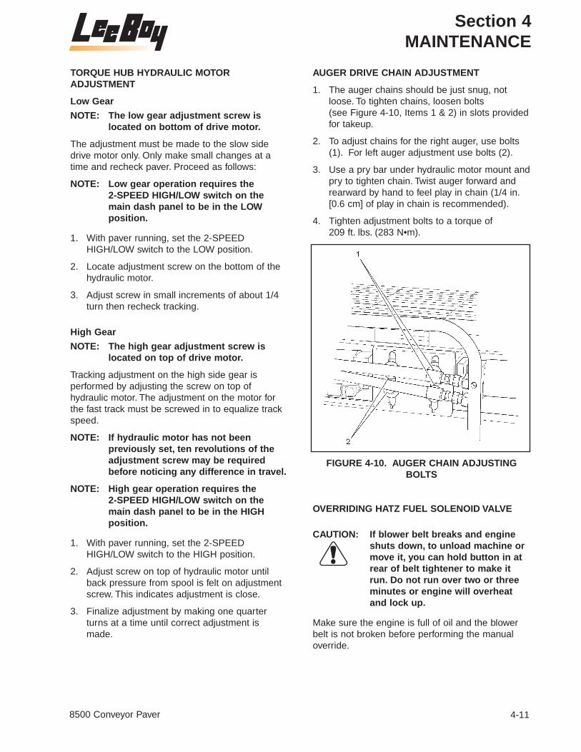
Section 4MAINTENANCE
4-118500 Conveyor Paver
TORQUE HUB HYDRAULIC MOTORADJUSTMENT
Low Gear
NOTE: The low gear adjustment screw islocated on bottom of drive motor.
The adjustment must be made to the slow sidedrive motor only. Only make small changes at atime and recheck paver. Proceed as follows:
NOTE: Low gear operation requires the 2-SPEED HIGH/LOW switch on themain dash panel to be in the LOWposition.
1. With paver running, set the 2-SPEEDHIGH/LOW switch to the LOW position.
2. Locate adjustment screw on the bottom of thehydraulic motor.
3. Adjust screw in small increments of about 1/4turn then recheck tracking.
High Gear
NOTE: The high gear adjustment screw islocated on top of drive motor.
Tracking adjustment on the high side gear isperformed by adjusting the screw on top ofhydraulic motor. The adjustment on the motor forthe fast track must be screwed in to equalize trackspeed.
NOTE: If hydraulic motor has not beenpreviously set, ten revolutions of theadjustment screw may be requiredbefore noticing any difference in travel.
NOTE: High gear operation requires the 2-SPEED HIGH/LOW switch on themain dash panel to be in the HIGHposition.
1. With paver running, set the 2-SPEEDHIGH/LOW switch to the HIGH position.
2. Adjust screw on top of hydraulic motor untilback pressure from spool is felt on adjustmentscrew. This indicates adjustment is close.
3. Finalize adjustment by making one quarterturns at a time until correct adjustment ismade.
AUGER DRIVE CHAIN ADJUSTMENT
1. The auger chains should be just snug, notloose. To tighten chains, loosen bolts (see Figure 4-10, Items 1 & 2) in slots provided for takeup.
2. To adjust chains for the right auger, use bolts(1). For left auger adjustment use bolts (2).
3. Use a pry bar under hydraulic motor mount andpry to tighten chain. Twist auger forward andrearward by hand to feel play in chain (1/4 in.[0.6 cm] of play in chain is recommended).
4. Tighten adjustment bolts to a torque of 209 ft. lbs. (283 N•m).
FIGURE 4-10. AUGER CHAIN ADJUSTINGBOLTS
OVERRIDING HATZ FUEL SOLENOID VALVE
CAUTION: If blower belt breaks and engineshuts down, to unload machine ormove it, you can hold button in atrear of belt tightener to make itrun. Do not run over two or threeminutes or engine will overheatand lock up.
Make sure the engine is full of oil and the blowerbelt is not broken before performing the manualoverride.

Section 4MAINTENANCE
4-12 8500 Conveyor Paver
CAUTION: If the manual override lever isused, the automatic shutdownsystem will not operate. Themachine manufacturer and theengine manufacturer will accept noliability for consequential damage,the warranty is invalidated. For thisreason, operate the engine only ina genuine emergency and for avery short period of time afterengaging the manual overridelever.
NOTE: Do not run without the cover.
To override, remove the top cover on the engine.Look on the oil filter side of the engine and you willsee the fuel solenoid and the extra fuel housingabove the oil filter. On top of the housing is a smalllever, break the lead seal on the right side of thelever and turn the lever clockwise to lock in. Theengine will now run until you unlock the overridelever.
TRACK TENSION PRESSURE RELIEF
Pressure Check
All part item numbers in the followingprocedure refer to the parts list for theSPROCKET DRIVE TRACK SYSTEM and theassociated drawing in the parts manual.
NOTE: Relief pressure is set at 700 PSI attrack tension manifold (45).
1. To check pressure, connect a 2000 PSI gaugeat one of the hoses going to the track tensioncylinder (32).
TRACK TENSION RELEASE
All part item numbers in the followingprocedure refer to the parts list for theSPROCKET DRIVE TRACK SYSTEM and theassociated drawing in the parts manual.
1. Locate manifold (45) under hopper to releasetrack tension.
CAUTION: Do not tamper with adjustmentpart of relief cartridge.
2. Back relief cartridge out of the aluminum blockabout three turns or until pressure release isheard.
3. Make sure cartridge is tightened before movingmachine.
CONVEYOR LIMIT SWITCH ADJUSTMENT
In order for the conveyor's start and stop to occurat the correct position, small adjustments may be necessary to the micro-switch (see Figure 4-11,Item 1) located on the conveyor flap (2). There aretwo positions of the conveyor flap: one upper,shutting the conveyor OFF, and one lower, turningthe conveyor ON. Read the following procedurescarefully, referring to the figures as needed.
1. Raise the conveyor flap (2) 6-1/2 to 7 in. (16.5to 17.8 cm) from bottom of the tank mountsupport (3). Secure conveyor flap so it remainsin this position. If micro-switch clicked OFFwithin the 6 1/2 to 7 in. (16.5 to 17.8 cm) limit,no further adjustment is required to the uppertravel.
2. If the micro-switch (2) did not click OFF,adjustment is needed. Remove the linkage (4)attaching the actuator arm (5) to the eyelet onthe flap pivot housing (6).
3. Loosen setscrew “A” (1), on the actuator arm (2). Reposition this arm by either rotating itclockwise or counterclockwise dependingwhere the micro-switch clicked OFF during theconveyor flaps upward travel (see Figure 4-12).
4. When the click OFF occurs between the 6-1/2to 7 in. (16.5 to 17.8 cm) limit, tighten setscrewand connect linkage.
5. If the lower flap travel does not fall into thelower limits, loosen setscrew “B” (1) on theactuator arm (2) slightly (see Figure 4-13).
NOTE: The setting from the factory is 1 in.(2.54 cm) from the center of thesetscrew “B” to the eyelet on theactuator arm.
6. To bring the travel limits into tolerance, slidethe actuator arm in the direction desired. Thismay require several adjustments before thecorrect position is obtained. When the actuatorarm is in the correct position, tighten setscrew“B”. No further adjustment is necessary.

Section 4MAINTENANCE
4-138500 Conveyor Paver
FIGURE 4-12. SETSCREW “A” LOCATION FIGURE 4-13. SETSCREW “B” LOCATION
FIGURE 4-11. CONVEYOR MICRO-SWITCH LOCATION

Section 4MAINTENANCE
4-14 8500 Conveyor Paver
SCREED EXTENSION TOP GUIDEADJUSTMENT
All part item numbers in the following procedurerefer to the parts list for the extendable screedassembly (Part I) and the associated drawing in theparts manual.
1. Using the SCREED LEFT EXTENSION andRIGHT EXTENSION IN/OUT handles, run thescreed extension in by pushing the lever fullyupward.
2. Locate the five 1/2″ bolts (41) that hold topguide (40) on. These bolts are located Inside ofcylinder cover at top and in center crown.
3. Loosen bolts holding guide and drive guidedown tight against slide (19) by using a bluntpunch. Stick punch through slots in 1/8″ shieldcovering top of extensions.
4. Run extension out and grease guide with multi-purpose grease before working.
NOTE: Guide should be greased daily toprevent wear.
5. Tighten the five 1/2″ bolts (41) securing guides(40) to a torque of 75 ft. lbs. (100 N•m).
BATTERY SERVICING
WARNING: Batteries contain sulfuric acid andnormally produce explosive gaseswhich can cause serious injury.Therefore, do not allow flames orsparks to come near the battery.When charging or working near abattery, always shield your faceand protect your eyes. In case ofacid contact with skin or eyes,flush immediately with water for aminimum of 15 minutes and getprompt medical attention. If acid isswallowed, call a physicianimmediately.
The paver electrical system is a 12-volt negativeground system. Keep sparks and flames away fromthe battery as electrolyte gas is highly flammable.The battery is located on the right side of theoperator's platform behind the disconnect switch(see Figure 4-14).
NOTE: When replacing the battery, discard theold battery properly.
FIGURE 4-14. BATTERY
CAUTION: When servicing the electricalsystem or welding on the machine,always turn the MASTER switch tothe OFF position to disconnect theground strap from the battery toprevent damage to the machineelectrical system.
Before connecting the battery, DISCONNECTswitch is turned off. Be certain that the terminalsand battery posts are thoroughly cleaned and thatthe battery cable terminals are tight. Dirty or looseconnections can create high electrical resistanceand permit arcing, which will quickly burn and pitterminals and posts.
NOTE: The electrical system is a negativeground system. Connect the positive(+) cable to the positive (+) post of thebattery. Connect the ground cable tothe negative (-) post of the battery. It isadvisable to disconnect the negative (-)cable first and connect it last.Reversed polarity can damage theelectrical system.
Keep the battery clean by washing it off wheneverdirt builds up is excessive. If corrosion is presentaround terminal connections, remove them andwash with ammonia solution or a solutionconsisting of 1/4 lb. (0.11 kg) baking soda added toone quart of warm water. Make certain the ventcaps are tight to prevent solution from entering thecells. After cleaning, pour clean water over the

Section 4MAINTENANCE
4-158500 Conveyor Paver
battery and surrounding area to wash the solutionaway. Check vent cap breather openings to makesure they are open.
Be sure to keep the battery fully charged duringcold weather to keep it from freezing. Freezingweather has little affect on a fully charged battery.
WARNING: When using a booster battery, donot attach the negative (-) cablefrom the booster battery to thenegative (-) post of the deadbattery. A spark could occur andcause an explosion of gasesnormally present around thebattery.
When connecting a booster battery, if necessaryfor cold weather starting, connect one end of thefirst jumper cable to the positive (+) terminal of thedead battery and the other end to the positive (+)terminal of the booster battery. Connect one end ofthe second jumper cable to the negative (-)terminal of the booster battery and the other end tothe frame of the machine with the dead battery.
The alternator supplies electrical current forcharging the battery and ample electrical power tothe electronic controls. The built-in regulator in thealternator controls the voltage output. If for anyreason the wires must be disconnected from thealternator, mark them so that they can bereconnected properly. Use the followingprecautions to prevent damage to the alternatorand/or regulator:
1. An alternator is never to be polarized. Neverground any alternator terminals or circuits.
2. Always disconnect the battery beforedisconnecting or connecting the alternator.Never disconnect the alternator with itoperating. Be certain the wiring is properlyconnected before connecting the battery.
3. Always connect a booster battery in the properpolarity. Negative (-) to negative (-) and positive(+) to positive (+).
WARNING: When finished using the machineat the end of the day, ALWAYS turnthe DISCONNECT switch to the“OFF” position. This will eliminatethe possibility of fire due to batteryor cable shorting
ENGINE MAINTENANCE
GENERAL INFORMATION
The following engine maintenance information willcover engine general maintenance proceduresmost often required.
For additional, very specific, engine maintenanceinformation, see the current “OPERATION ANDMAINTENANCE MANUAL” - Hatz engine.
ENGINE LUBRICATION OIL
Checking the Engine Lubrication Oil Level
The engine lubrication oil must be kept at a levelabove the “ADD” mark, but not above the “FULL”mark, on the engine lubrication oil dipstick.
To accurately check the engine lubrication oil level,put the machine in a "level" position and stop theengine. Clean the area around the enginelubrication oil dipstick before removing the dipstickfrom the engine. Wait five minutes, after engineshutdown, before removing the dipstick from theengine and checking the oil level.
NOTE: The above procedure will help toremove the possibility of filling theengine with too much lubrication oil,by allowing the oil to return to the oilpan.
WARNING: Stop the engine before checkingthe engine lubrication oil level.With the engine running, hot oilcan be thrown causing seriousinjury.
FIGURE 4-15. HATZ ENGINE

Section 4MAINTENANCE
4-16 8500 Conveyor Paver
Changing the Engine Lubrication Oil
The engine lubrication oil must be changedaccording to the interval given in the current HatzDiesel engine “OPERATION AND MAINTENANCEMANUAL”.
NOTE: The color of the engine lubrication oilcan not be used as an indication of theneed for a engine lubrication oilchange. The use of an enginelubrication oil “analysis service” is theonly alternate reason for not followingthe required engine lubrication oilchange schedule.
WARNING: Do not change the enginelubrication oil when the engine andlubrication oil are hot. Changewhen warm only. Hot oil can causeserious injury.
CAUTION: Do not change the engine lubricationoil with the engine “running”.Serious engine damage, or failurewill occur. Clean the area around theengine lubrication oil dipstick and oilfiller cap before removing thedipstick, or oil filler cap.
With the engine “stopped”, and the enginelubrication oil is “warm”, proceed as follows:
1. Clean the area around the engine lubricationoil drain plug found on the engine oil pan.
2. Place a container, having a capacity sufficientto hold the drained oil, directly under theengine lubrication oil drain plug.
3. Carefully remove the engine lubrication oildrain plug.
4. Using hose and fitting from the tool box, drainall of the engine lubrication oil into thecontainer.
5. Clean, install and carefully tighten thelubrication oil drain plug.
CAUTION: Do not overtighten the drain plug.
6. Fill the engine with 12 qts (11.3 liters) of oil,using the correct engine lubrication oil.
NOTE: See this section for the correct amountof lubrication oil. For the correct typeof lubrication oil see the current“OPERATION AND MAINTENANCEMANUAL” - for the Hatz engine.
7. Install the engine lubrication oil dipstick.
CAUTION: Do not start the engine beforechanging the engine lubrication oilfilter. Follow the procedures givenin this section and in the currentHatz engine manual.
Changing The Engine Lubrication Oil Filter
The engine lubrication oil filter must be changedwhen the engine lubrication oil is changed.
WARNING: Do not change the enginelubrication oil when the engine andlubrication oil are hot. Changewhen warm only. Hot oil can causeserious injury.
CAUTION: Do not change the enginelubrication oil filter with the enginerunning. Serious engine damage,or failure, will occur.
With the engine “stopped” and filled with newengine lubrication oil, proceed as follows:
1. Wipe the area around the engine lubrication oilfilter element and its mounting base, with aclean cloth.
2. Place a container under the filter element.
3. Use a filter removal wrench to loosen andremove the filter element by turning it in acounterclockwise direction of rotation. Drainand discard the removed filter element.
NOTE: Be sure the used rubber gasket isremoved and discarded with the filterelement.
4. Wipe the inside area of the lubrication oil filterhead using a clean lint free cloth.
5. Put clean engine lubrication oil on the rubbergasket area of the new filter element. Fill thenew filter element with correct, new, and cleanoil.
6. Install the new filter element onto the filterhead. Carefully tighten the filter element, byhand only.
NOTE: Tighten the filter element as directedon the filter element, by the filtermanufacturer.

Section 4MAINTENANCE
4-178500 Conveyor Paver
FUEL SYSTEM
Fuel Tank
The fuel level is indicated on the dash panel FUELgauge and indicates the amount of fuel in the tank.Fill the fuel tank “FULL”. Also fill the tank, to “FULL”,before the machine is stored for the night to reducethe accumulation of moisture, in the tank, fromcondensation.
WARNING: The operator must be off of themachine while fuel is added. Nosmoking while filling the fuel tank.All fuels for internal combustionengines are flammable. Fill the fueltank only in a designated area withgood ventilation. Have a fireextinguisher available.
Never fill the tank near an openflame, or near equipment that cancreate sparks. Never check fuellevel or check for fuel leaks withan open flame.
Engine Fuel Filters
The fuel filter element must be replaced asdirected in the current Hatz engine manual.Replace the fuel filter using the following “general”procedure and very specific information given inthe current engine manual.
WARNING: Diesel fuel is very flammable. Useextra caution.
Do not change the fuel filter withthe machine running.
Do not change the fuel filter in anarea near an open flame.Do notsmoke while changing the fuelfilter.
Do not spill fuel.
1. Stop the engine.
2. Put a container under the fuel filter, beforeremoving the filter element.
3. Wipe the area around the fuel filter elementand the element mounting head, using a cleanlint free cloth.
4. Use a filter removal wrench to loosen andremove the element, by turning the element ina clockwise direction. Drain and discard theremoved element.
5. Wipe the inside area of the filter head with aclean “lint free” cloth. Fill the “new” fuel filterelement completely full of the correct and cleanfuel. Put clean fuel on the element rubbergasket.
6. Install the “new” fuel filter element onto the filter head. Carefully tighten the element byhand only.
CAUTION: Tighten the fuel strainer or the fuelfilter element as directed on thefilter element, by the filtermanufacturer. Do not overtightenthe fuel filter element onto the filterhead.
7. Start the engine and check for ANY fuel leaks.
WARNING: Stop the engine immediately if anyfuel leakage is noted. Do not startthe engine until the leakageproblem is corrected.
Engine Air Filter
The engine inlet air filter assembly uses areplaceable filter element.
CAUTION: The air filter element should bereplaced one time for each 100hours of machine operation, ormonthly, for a machine which isoperated under “normal”conditions, or more often for amachine that is operated under"very severe” conditions. Neveroperate the engine without an aircleaner element installed.
Do not service the air cleanerelement while the engine is“running”.
Use the following procedures to service the aircleaner element:
1. Remove the two screws and plate securingeach air filter cover over the air filters at the topof the engine.
2. Remove the air filter covers.
3. Remove the air filter elements from the engineand discard.

Section 4MAINTENANCE
4-18 8500 Conveyor Paver
4. Clean the inside of the air cleaner body with aclean cloth.
CAUTION: Severe engine damage can occur ifengine is operated without air filterproperly installed.
5. Carefully install the new air filter elements intothe intake at the top of the engine.
6. Install the covers over the filters.
7. Secure each cover with the two screws andplate.
8. Start the engine using all the correct startingprocedures given in Section 3 - OPERATION ofthis manual. Check that engine runs smoothly.
HYDRAULIC SYSTEM
GENERAL INFORMATION
The hydraulic motors and the hydraulic cylindersuse the same hydraulic oil reservoir and hydraulicoil supply.
CHECKING THE HYDRAULIC OIL LEVEL ANDADDING HYDRAULIC OIL TO THE HYDRAULICOIL RESERVOIR
Check the hydraulic reservoir oil level, one timeeach day, by removing the petcock on the reservoir(see Figure 4-16). Check the oil level when thehydraulic oil is at "normal" operating temperatureonly.
WARNING: Do not loosen, or remove, thehydraulic oil reservoir filler capwhen the hydraulic oil is “HOT”.always loosen the filler cap slowlyto relieve any pressure in thehydraulic oil reservoir.
Only loosen the filler cap when theoil is at a “WARM” temperature.
The hydraulic reservoir oil level must be able to flowfrom the petcock to be at the correct level. If thehydraulic oil level is below the petcock, the correct,filtered hydraulic oil must be added to the hydraulicoil reservoir until the oil level is at least to thepetcock. See this section for the correct type of oil.
CAUTION: Do not over fill the hydraulic oilreservoir.
Do not use unfiltered hydraulic oil.The new hydraulic oil must befiltered before it enters thehydraulic oil reservoir. Keep the oillevel of the hydraulic oil reservoir,at the correct level. An air space isdesigned into the hydraulic oilreservoir and allows for oilexpansion, at warm temperatures.The hydraulic oil reservoir willhave a low pressure in it at systemoperating temperatures.
FIGURE 4-16. HYDRAULIC OIL TANK

Section 4MAINTENANCE
4-198500 Conveyor Paver
CHANGING THE HYDRAULIC OIL
Changing the hydraulic oil removes theaccumulation of dirt, water and mechanical wearparticles from the hydraulic oil reservoir and system.The chemical structure of the hydraulic oil alsochanges after continuous use in the system andnew, clean, and filtered oil is a must to help insurefurther correct operation of the hydraulic system.
CAUTION: Hydraulic oil which has oxidized orwhich contains contamination, ofany type, can shorten the expectedservice life of any, or all, of thecomponents in the hydraulicsystem.
Use the following procedures to change the hydraulicoil in the hydraulic oil tank (see Figure 4-16).
1. Stop the engine. Allow the hydraulic oil to cool,until it is at a warm temperature only. Slowlyloosen, and then remove, the hydraulic oilreservoir filler cap (2). Put a CLEAN, lint freecloth over the reservoir fill tube opening andsecure in place with tape.
WARNING: Do not drain the hydraulic oil fromthe reservoir when it is “HOT”. Hothydraulic oil can cause seriousinjury. Drain at a warm temperatureonly.
NOTE: All three reservoir tanks together plushoses hold approximately 40 gallons.
2. Carefully remove the plugs from the hydraulictanks. Use a drain collection device, ofsufficient capacity to collect the hydraulic oil.Allow all of the hydraulic oil to drain from thereservoirs and into the container.
CAUTION: Do not fill the hydraulic oilreservoir with new hydraulic oiluntil the strainer has beenserviced.
3. Install the hydraulic oil reservoir drain plug, andtighten securely.
4. Carefully remove the cloth from the hydraulicoil reservoir fill tube opening.
5. To be sure the bottom oil tank is properly filled,proceed as follows:
a. Remove the strainer on the top tank.
b. Fill the top hydraulic oil tank with thecorrect, filtered hydraulic oil until tank isfull.
c. Crank engine and let pump transfer oilfrom top tank to bottom tank.
d. Monitor oil level in top tank. When oil levelis below one-half full, shut off engine andrefill top tank.
e. Repeat this process until proper level isobtained.
CAUTION: Do not overfill the hydraulic oilreservoir with oil.
CAUTION: Never let tank run dry. Pumpdamage will occur.
6. Check the oil level in the hydraulic oil reservoir,again. Add oil if needed.
7. Install the hydraulic oil reservoir filler cap ontothe reservoir filler neck and tighten securely.
8. Start the engine using the correct proceduresgiven in Section 3 - OPERATION of thismanual. Check the hydraulic system for anyleaks.
WARNING: Do not use the hands on anyhydraulic hose, fitting or systemcomponent to check the systemfor possible leaks. Serious injurycan result from an oil leak underhigh pressure. Oil can be injectedunder the skin by high pressure.Protect the eyes by wearing safetyglasses.
CAUTION: Stop the engine immediately if anyhydraulic leak is noted. Do notstart the engine until any problemnoted has been corrected.

Section 4MAINTENANCE
4-20 8500 Conveyor Paver
CHANGING THE HYDRAULIC OIL STRAINER
The oil strainer is mounted in the oil filler openingunder the filler cap.
WARNING: Do not REMOVE the hydraulic oilCAP from the reservoir when it is“HOT”. Hot hydraulic oil can causeserious injury. Allow hydraulic oilto cool down to a warmtemperature .
1. Remove the hydraulic oil filler cap (2).
2. Remove the three screws securing the strainer,then remove the strainer and the gasket.
3. Install a new gasket, aligning the three holes inthe gasket with the mounting holes on thereservoir.
4. Install the new strainer, aligning the holes inthe strainer with the mounting holes of thegasket and secure the strainer with the threescrews.
5. Fill the hydraulic oil reservoir with the correct,filtered hydraulic oil until oil flows from thepetcock (1).
CAUTION: Do not overfill the hydraulic oilreservoir with oil.
6. Check the oil level in the hydraulic oil reservoir,again. Add oil if needed.
7. Install the hydraulic oil reservoir filler cap ontothe reservoir filler neck and tighten securely.
REMOVAL AND INSTALLATIONPROCEDURES
TRACK COMPONENT REPLACEMENT
Rear Axle Assembly or Track
All part item numbers in the followingprocedure refer to the parts list for theSPROCKET DRIVE TRACK SYSTEM and theassociated drawing in the parts manual.
1. Raise conveyor and locate track tensionmanifold (45), then back the relief cartridge outof aluminum block about 3 turns or until youhear pressure release.
2. Rotate track so that master link is at the rearbottom of front idler (28) and then removemaster pin (16). Once the master pin isremoved, back machine until the track lays flaton the ground.
3. Jack machine up on side that needs repair.
4. Remove cutoff cylinder mounting bracket.
5. Remove the two 5/8″ bolts (12) andlockwashers (11) attaching pillowblock bearing(10). Axle assembly (7) will pry off of torquehub (2) onto the ground.
NOTE: Always place some axle grease intothe splines on axle when installing.
6. Replace sprocket (8) or axle (7) then placeback on machine.
7. Torque bolts attaching pillowblock bearing (10)to 180 ft. lbs. (244 N•m).
8. Lower sprocket back down toward track chain,keeping sprocket about 1″ out of chain.
NOTE: LeeBoy uses a 4 ft. (1.2 m) long x 11/16 in.(2 cm) dia. rod with a 2 in. (5.08 cm) leg onone end and a handle on the other end topull on and reach in over the axle and intochain so that when you spin the sprocketthe track can be pulled around with thehelp of the machine.
9. Pull track to front of machine so that tracklaying on ground can be hooked on to, thenreverse sprocket to rotate track to top so thatmaster pin (16) will go in at rear of idler (28).
10. Tighten tension relief, start machine, and rotatethe track to make sure it is O.K. When finishedremove the jack.

Section 4MAINTENANCE
4-218500 Conveyor Paver
Idler
All part item numbers in the followingprocedure refer to the parts list for theSPROCKET DRIVE TRACK SYSTEM and theassociated drawing in the parts manual.
1. Raise conveyor and locate track tensionmanifold (45), then back the relief cartridge outof the aluminum block about three turns or untilyou hear the tension pressure release.
2. Rotate track so that the master link is at therear bottom of the front idler (28), then removethe master pin (16). Once master pin isremoved, back up the machine until the trackclears the front idler.
3. Jack up the machine on the side needing to berepaired.
4. Remove the clip pin from the cylinder rod andidler bracket.
5. The idler will slide straight out.
6. Remove idler bracket and bolt to new idler.
7. Install idler making sure cylinder and clip pinare in correct position.
8. Lower sprocket back down toward track chain,keeping sprocket about 1 in. (2.54 cm) out ofchain.
NOTE: LeeBoy uses a 4 ft (1.2 m) long x 11/16 in.(2 cm) dia. rod with a 2 in. (5.08 cm) leg onone end and a handle on the other end topull on and reach in over the axle and intochain so that when you spin the sprocketthe track can be pulled around with thehelp of the machine.
9. Pull track to front of machine so that tracklaying on ground can be hooked on to, thenreverse sprocket to rotate track to top so thatmaster pin (16) will go in at rear of idler (28).
10. Tighten tension relief, start machine, and rotatethe track to make sure it is O.K. When finishedremove the jack.
Cylinder
All part item numbers in the followingprocedure refer to the parts list for theSPROCKET DRIVE TRACK SYSTEM and theassociated drawing in the parts manual.
1. Raise conveyor and locate the track tensionmanifold (45). Then, back the relief cartridge
out of the aluminum block about three turns, oruntil you hear the tension pressure release.
2. Rotate the track so that the master link is at therear bottom of the front idle (28). Then removethe master pin (16). Once the master pin isremoved, back the machine until the trackclears the front idler.
3. Jack up the machine on the side needing to berepaired and remove the front track roller.
4. Remove the clip pin from the cylinder rod andthe idler bracket.
5. The idler will slide straight out at this time.
6. Grab the cylinder and pull it toward the front sothat you can remove the hose from the cylinderbottom.
7. Replace the cylinder or repack the seal kit andinstall in machine.
8. Install the idler making sure the cylinder andthe clip pin are in correct position.
9. Lower sprocket back down toward track chain,keeping sprocket about 1 in. (2.54 cm) out ofchain.
NOTE: LeeBoy uses a 4 ft (1.2 m) long x 11/16 in.(2 cm) dia. rod with a 2 in. (5.08 cm) leg onone end and a handle on the other end topull on and reach in over the axle and intochain so that when you spin the sprocketthe track can be pulled around with thehelp of the machine.
10. Pull track to front of machine so that tracklaying on ground can be hooked on to, thenreverse sprocket to rotate track to top so thatmaster pin (16) will go in at rear of idler (28).
11. Tighten tension relief, start machine, and rotatethe track to make sure it is O.K. When finishedremove the jack.
Rollers
All part item numbers in the followingprocedure refer to the parts list for theSPROCKET DRIVE TRACK SYSTEM and theassociated drawing in the parts manual.
1. Raise the conveyor and locate the track tensionmanifold (45). Then back the relief cartridge outof the aluminum block about 3 turns or untilyou hear the tension pressure release.
2. Jack the machine up on the side needing therepair.

Section 4MAINTENANCE
4-22 8500 Conveyor Paver
3. Remove the rollers that are faulty and replacethem with new ones. Torque bolts to 90 ft. lbs.(122 N•m).
4. Tighten the tension relief. Then start themachine and rotate the track to make sure it isO.K. When finished remove the jack.
TORQUE HUB REPLACEMENT
All part item numbers in the followingprocedure refer to the parts list for theSPROCKET DRIVE TRACK SYSTEM in the parts manual.
Removal
1. Jack paver up about 24 in. (61 cm) off ofground on jackstands
2. Raise conveyor and place safety prop inposition.
NOTE: Do not disconnect hoses from thehydraulic drive motor.
NOTE: Seal (49) and snap ring (50) shouldonly be removed when replacement isnecessary.
3. Remove the two capscrews (6) andlockwashers (5) attaching the hydraulic drivemotor (4) to the torque hub drive (2). Slide themotor, hydraulic motor seal (49), snap ring(50), and o-ring (3) out and place the drivemotor up on frame out of the way.
NOTE: Performing the next step eliminates theneed to remove the track and axleassembly (7).
4. Weld a brace to go from rear of frame acrossaxle top against frame at another location.Place about a 1 in. (2.54 cm) weld at eachlocation to hold axle in place.
5. Remove the twelve 5/8″ bolts from torque huband pry torque hub out onto a floor jack. Alsoremove the torque hub drive shaft seal (48).
Installation
NOTE: The torque hub on the right side isrotated one (1) bolt hole different thanthe left side.
1. Put wheel bearing grease on axle splines ofnew or replacement torque hub (2).
2. Install torque hub drive shaft seal (48).
3. Insert spline of torque hub into axle (7) and alignthe twelve mounting holes for the torque hub.
4. Attach the torque hub to the frame with thetwelve 5/8″ bolts.
5. Torque bolts to 230 ft. lbs. (311 N•m).
6. Install o-ring (3).
7. Attach seal (49) and spacer with snap ring (50)(only if previously removed).
8. Attach hydraulic motor (4) with lockwashers (5)and capscrews (6).
9. Torque capscrews to 78 ft. lbs (106 N•m).
10. Remove the welds.
11. Lower the paver off the jackstands.
WARNING: Do not use the hands on anyhydraulic hose, fitting or systemcomponent to check the systemfor possible leaks. Serious injurycan result from an oil leak underhigh pressure. Oil can be injectedunder the skin by high pressure.Protect the eyes by wearing safetyglasses.
12. Start the engine using the correct proceduresgiven in Section 3 - OPERATION - of thismanual. Check the hydraulic system for anyleaks.
CAUTION: Stop the engine immediately if anyhydraulic leak is noted. Do notstart the engine until any problemnoted has been corrected.
REAR CONVEOR SHAFT REPLACEMENT
All part item numbers in the followingprocedure refer to the parts list for theSPROCKET DRIVE TRACK SYSTEM in the parts manual.
Removal
1. Rotate flight chains (12) until C-188 master pin(15) is located. When located, rotate the masterpin to the rear of the conveyor drive sprocket.
NOTE: If the shaft (8) is broken, the frontshield with rubber needs to beremoved, then push against the outeredge of the conveyor bars to make thechains rotate.
2. Remove grating walkway from paver so that youcan reach in to the center of conveyor at rear, orlay in under engine platform to reach center.

Section 4MAINTENANCE
4-238500 Conveyor Paver
3. Push back the rubber shield at the center ofthe conveyor at the rear so that the snap ring(9) can be removed off the shaft.
4. Run screed extension out fully on side to bechanged.
NOTE: The front screed arm bolt may need tobe removed to tilt arm out of the way.
5. Remove the chain guard and 80 chain thatdrives the conveyor.
NOTE: The flight chains can be loosened toallow the shaft to come out easier.
6. Remove capscrew (1) and countersunk washer(2) then remove the outer 80 drive sprocket (3).
7. Remove the four capscrews (10) and washers(11), then remove conveyor mounting plate withbearing (4).
NOTE: Do not remove the master pin on theinner C-188 chain. Let the sprocket andchain stay together.
8. Remove C-188 master link (13) and lay thechain away from the sprocket on the outer side.
9. The rear shaft (8) and outer C-188 sprocket (5)will pull straight out at this time.
Installation
1. Slide the new shaft (8) in and align the inner C-188 sprocket (6) onto the spline shaft.
2. Install the snap ring (9) on and fasten therubber shield back.
3. Install the outer C-188 sprocket (5), be surethat the teeth are in line with the inner C-188sprocket.
4. Install the pivot bearing plate (4) using the fourcapscrews (10) and lockwashers (11).
5. Apply loctite on taper head bolt (1).
6. Attach the outer drive sprocket (3) with taperheaded bolt (1) and countersunk washer (2).
7. Put 80 chain on and lubricate the chain.
8. Adjust chain for about 1/4 in. (0.64 cm) play.
9. Place chain guard back on.
10. Hook screed arm in place.
11. Adjust main flight chains and let the conveyorsrun for a short period of time. Then recheck thechain adjustment.
12. Place grating back on when finished.
NOTE: Conveyors should be adjusted aboutevery 100 hours to avoid damage tothe conveyor rear shafts and thechains.
NOTE: Keep the conveyors clean and welllubricated.
NOTE: If the conveyor or flight chains areadjusted all the way out, locate themaster link and remove it. Remove 1 block link and 2 sidebars on eachchain, then replace with C-188 1/2links. (There is not enough room totake a link out without installing a 1/2 link back).
AUGER AND INNER BEARING REPLACEMENT
All part item numbers in the followingprocedure refer to the parts list for the AUGERASSEMBLY in the parts manual.
Removal
1. Remove rear grating over auger assembly.
2. Run screed extension all the way out.
NOTE: This provides room to stand in behindauger back to remove top portion ofauger cover. Auger cover is in threepieces with a small tack to hold covertogether while building.
3. Remove four nuts holding cover (6) on and prycover apart.
4. Clean asphalt build up from around cover.(Heating asphalt may be required).
5. Remove middle and bottom portion of cover bylaying on conveyor under engine.
6. Rotate augers so that master link (4A) iscentered at front.
7. Loosen auger chains (4) by sliding augermotors (1) down from backside after looseningthe two bolts securing mounting brackets (3).
8. Remove auger endmounts (9 or 9A) so thataugers can be removed through opening insides.
9. Remove augers (16 or 18) and lay augers onthe ground in the same position as removed.This will help insure proper installation of thenew augers.

Section 4MAINTENANCE
4-24 8500 Conveyor Paver
10. Check inner auger bearing (15) and replace atthis time if faulty.
Installation
NOTE: When installing the new augers besure to align augers the same as theremoved augers. It is very easy toinstall augers backwards.
1. Install new augers (16 or 18) making sure thatwearplates are on correct side to augermaterial outward.
2. Tighten bearing setscrew to help hold augershaft from moving outward.
3. Slide auger collar (7) on end of auger shaft andbolt endmount (9) back on. Torque mountingscrews to 78 ft. lbs. (106 N•m)
4. Push collar (7) all the way in against endmount(9) and attach with setscrews (11) (foursetscrews, two on outside and two on inside).
5. Replace bronze bushing (8) in the endmounts.
6. Place auger chains back on and adjust augermotors (1) up to tighten chains. Use a pry barunder motor to pry up, then snug bottom motormount bolts (make sure chains haveapproximately 1/4″ of slack).
7. Make sure motor is level then tighten top and bottom bolts. to a torque of 150 ft. lbs.(155 N•m). Do the same for the other side.
8. Lubricate chains.
9. Place auger cover (6) back in place makingsure slot for auger shaft is sealed shut.
10. Place grating back on over auger.
11. Run augers and make sure everything iscorrect.
NOTE: Auger chains can be lubricated eachday by spraying oil or chain lube inthrough slots where auger motor isadjusted.
SCREED EXTENSIONS, SLIDES OR BUSHINGREPLACEMENT
All part item numbers in the followingprocedure refer to the parts lists for theEXTENDABLE SCREED ASSEMBLY PART IAND PART II in the parts manual.
Removal
1. Remove cylinder covers (9 and 10, PART II).
2. Run screed extension out completely.
3. Remove cylinder pin (lower screed) (25, PART I).
4. Remove the four 1/2″ bolts (20), lockwashers(21), and flat washers (22) in extension rods(17) holding the extension (4 and 4A) on.
5. After bolts have been removed, pull extension(4 and 4A) out of the way.
6. Pull 1-1/2″ rods (17) out of slide (19).
7. Loosen five bolts (41), lockwashers (42) andflat washers (43) attaching top guide. This willlet main slide (19) come out easily. At this timebushings (2) can be replaced or main slide canbe replaced.
NOTE: When replacing bushings, thebushings need to be honed if 1-1/2″″rods (17) do not slide in.
Installation
1. Clean area where slides (19) are installed, andlubricate before sliding the slide back in.
2. Loosen guide (40) and drive guide down tightagainst slide by using a blunt punch. Stickpunch through slots in 1/8″ shield covering thetop of extensions.
3. Slide 1-1/2″ rods (17) back into slide (19).
4. Secure rods (17) with capscrew (20),lockwasher (21), and flat washers (22).
5. Make sure extension is mounted flush withbottom of screed plate.
6. Hook cylinders (23) back to extensions usingpin (25) and put cylinder cover (9 and 10,PART II) back on.
7. Run extension out and grease the extensionwell before operating “in” and “out”.
SCREED WEARPLATE REPLACEMENT
All part item numbers in the followingprocedure refer to the parts lists for theEXTENDABLE SCREED ASSEMBLY PART IAND PART II in the parts manual.
Removal
1. Run screed extension all the way in.
2. Remove the cylinder covers, (9 and 10, PARTII) the walkboards (11), and the screed lids (7).

Section 4MAINTENANCE
4-258500 Conveyor Paver
3. Remove the ten 3/8″ bolts holding thewearplate (6, PART I) to the screed frame oneach side.
4. Clamp the center portion of the screed frameso that when the screed frame is raised up offthe worn wearplate the clamp will hold theframe in place.
5. Raise the screed up and remove the wornwearplate.
6. Clean all material buildup from the screedframe before bolting in the new wearplate.
Installation
1. Set the new wearplate down level on 3 blocks,placing one block in the center and one at eachend. Make certain the extensions are raised allthe way up to prevent extensions from holdingthe screed frame off the wearplate.
2. Lower the screed frame down on the newwearplate.
NOTE: Do not tighten the bolts in the nextstep until all the bolts are installed.
3. Install five bolts in one side at the front to holdthe wearplate.
4. Loosen the vibrator on the slotted side andadjust the crown. This will move the screedframe in and out on the wearplate to help alignthe bolts on the opposite side.
5. Once the front bolts are installed install the rearbolts.
6. When all of the bolts have been started makesure the screed frame and the wearplate areflat.
7. Torque bolts to 55 ft. lbs. (74 N•m). Start insideand move outward by rotating from the left tothe right side. This will keep the screed relaxed.
8. Place the screed lids, the walkboards and thecylinder covers back on the screed.
EXTENSION WEARPLATE REPLACEMENT
All part item numbers in the followingprocedure refer to the parts lists for theEXTENDABLE SCREED ASSEMBLY PART IAND PART II in the parts manual.
Removal
1. Run the extensions all the way out.
2. Remove the endgates by removing the tiltscrew and 7/8″ nut on each side. The endgatewill tilt forward out of the holder and slide offthe 7/8″ bolt.
3. Disconnect the extension adjuster (7) from thewearplate (5), by removing locknut (13),washer, and capscrew (12).
4. Remove the front extension hinge shield.
5. Slide the hinge pin (44) out and the wearplate(5) will fall off.
Installation
1. Hold the new wearplate (5) in place and slidethe hinge pin (44) in place.
2. Fasten the extension adjuster (7) back to thewearplate (5) with locknut (13), washer, andcapscrew (12).
3. Put the front hinge shield back on.
4. Install endgate and tilt screw back on thepaver.
TANDEM SERVO PUMP REPLACMENT
All part item numbers in the followingprocedure refer to the parts lists for the PUMPCOMPONENTS SUNDSTRAND ELECTRONICSTEERING in the parts manual unlessotherwise indicated.
Removal
1. Part item numbers in the following substepsrefer to the parts lists for the SHEET METALCOVER in the parts manual.
a. Remove the right side cover (14).
b. Remove the right side access door cover(8).
c. Remove the top right side cover (2) andright side cover (15).
2. Label and disconnect the hoses to the tandempropulsion hydraulic pump (15), plugging thehoses and capping the fitting on the hydraulicpump.
3. Label and disconnect the hoses to the tandemauxiliary hydraulic pump (16), plugging thehoses and capping the fitting on the hydraulicpump.
NOTE: If Tandem Auxiliary Pump is not badleave hoses attached and slide out ofMain Pump.

Section 4MAINTENANCE
4-26 8500 Conveyor Paver
WARNING: Pump assembly is very heavy andmust be properly supported with asling before loosening mountingbolts.
4. Place a sling around the pump assembly toprovide support.
5. Remove the two screws attaching pumpassembly (16) to the pump plate cover.
6. Slide the pump assembly off of the splinedshaft.
7. Using the sling, lift pump assembly (16) withauxiliary pump assembly (15) out of paver andplace on a flat surface.
8. Remove the two screws attaching the tandemauxiliary hydraulic pump (15) to the tandempropulsion hydraulic pump (16).
9. Remove the o-ring from between the pumps.
Installation
1. Place a small amount of hydraulic oil on the o-ring and install o-ring between the pumps.
2. Carefully support auxiliary pump (15) and alignthe mounting holes in the auxiliary pump (15)with the mounting on pump (16).
3. Attach the pumps with the two mountingscrews.
4. Torque the screws to 89 ft. lbs. (121 N•m).
WARNING: PUMP ASSEMBLY IS VERY HEAVYAND MUST BE PROPERLYSUPPORTED WITH A SLINGBEFORE LIFTING INTO PAVER.
5. Support the complete pump assembly with asling and lift assembly into paver.
6. Carefully slide pump assembly onto splinedshaft and align mounting holes with the pumpplate cover mounting holes (grease splinesbefore installing).
7. Attach the pumps with the two mountingscrews.
8. Torque the screws to 89 ft. lbs. (121 N•m).
9. Remove plugs and caps and connect hydraulichoses to pumps are previously labeled.
10. Check hydraulic oil level in tank and addhydraulic oil if necessary.
11. Part item numbers in the following substepsrefer to the parts lists for the SHEET METAL
COVER in the parts manual.
a. Install the right side cover (14).
b. Install the right side access door cover (8).
c. Install the top right side cover (2) and rightside cover (15).
12. Install the spray hose assembly on the top rightside cover.
13. Start the paver.
14. Check to be sure there is no hydraulic oil leaks.
2-SPEED HYDRAULIC MOTOR REPLACEMENT
All part item numbers in the followingprocedure refer to the parts lists for theSPROCKET DRIVE AND TRACK SYSTEM in theparts manual.
Removal
1. Turn the paver off.
2. Check to be sure there is no hydraulicpressure.
3. Label and disconnect the hoses to thehydraulic motor (4), plugging the hoses andcapping the fitting on the hydraulic motor.
4. Support hydraulic motor, then remove the twoscrews (6) and lockwashers (5) attaching thehydraulic motor to the torque hub and carefullyremove the motor from the torque hub.
5. Remove the o-ring (3).
6. Drain the hydraulic oil from the hydraulic motor.Discard or repair the hydraulic motor asappropriate.
Installation
1. Lubricate a new seal (3) with hydraulic oil andinstall on torque hub.
2. Attach hydraulic motor to torque hub using twocapscrews (6) and lockwashers (5).
3. Torque capscrews (6) to 120 ft. lbs (163 N•m).
4. Remove plugs from hydraulic hoses andconnect the hydraulic hoses in accordance withthe labels.
5. Operate paver and check for leaks.
NOTE: When installing motor dry, crank andlet run for approx. 10 minutes to workair out of system before engaging tomove.

Section 4MAINTENANCE
4-278500 Conveyor Paver
2 SPEED WIRING DIAGRAM
FUSE BLOCK
FRONT & REARWORK LIGHTS

Section 4MAINTENANCE
4-28 8500 Conveyor Paver
LEFT CONVEYOR WIRING DIAGRAM
RIGHT CONVEYOR WIRING DIAGRAM

Section 4MAINTENANCE
4-298500 Conveyor Paver
SPECTRA GRADE CONTROL L/B DRIVE WIRING DIAGRAM
SPECTRA GRADE CONTROL (with Slope add-on) ELECTRONIC STEERING WIRING DIAGRAM

Section 4MAINTENANCE
4-30 8500 Conveyor Paver
SPECTRA GRADE CONTROL (with Slope add-on) L/B DRIVE WIRING DIAGRAM
STANDARD GRADE CONTROL L/B DRIVE WIRING DIAGRAM

Section 4MAINTENANCE
4-318500 Conveyor Paver
STANDARD GRADE CONTROL L/B DRIVE TOPCON WIRING DIAGRAM
MOBA AUGER WIRING DIAGRAM

Section 4MAINTENANCE
4-32 8500 Conveyor Paver
TSD AUGER WIRING DIAGRAM

Section 4MAINTENANCE
4-338500 Conveyor Paver
HYDRAULIC SCHEMATIC (Sheet 1 of 2)

Section 4MAINTENANCE
4-34 8500 Conveyor Paver
HYDRAULIC SCHEMATIC (Sheet 2 of 2)

TROUBLESHOOTING
GENERAL
The troubleshooting chart below identifies the mostcommon sypmtoms of failure. Use this chart to helpidentify the failed component. A separateTroubleshooting guide is provided for
troubleshooting the steering system. This alsoincludes a Wiring Diagram (see Figure 4-19) and aTroubleshooting Logic Procedure (see Figure 4-20).
TROUBLESHOOTNG CHART
SYMPTOM CAUSE REMEDY
Replace or charge battery asapplicable
Set switch to the ON position
Center steering control to switch
Fill fuel tank
Refer to Hatz engine manual
Replace
Make sure wires are tight
Plug back
Clean plunger
Replace coil
Replace belt
Replace or rebuild
Replace
Replace
Add fuel to fuel tank
Replace belt
Replace solenoid
Replace or rebuild
Replace
Defective battery or low batterycharge
MASTER switch not in ONposition
Steering control not centered
Insufficient fuel supply
Fault in engine
Safety switch faulty
Wires not making goodconnection on solenoid
Plug in switch box unplugged
Solenoid plunger sticking
Fuel solenoid coil defective
Blower belt broken
Starter or solenoid faulty
Neutral switch defective
Hatz start relay faulty
Low fuel
Blower belt broken
Faulty fuel solenoid
Faulty alternator
Idiot light, bad bulb
Engine does not start
Engine cuts off and willnot start. (Turns over butwill not start)
Low Battery
Section 4MAINTENANCE
4-358500 Conveyor Paver

Section 4MAINTENANCE
4-36 8500 Conveyor Paver
TROUBLESHOOTNG CHART (Continued)
SYMPTOM CAUSE REMEDY
Check RUN/STOP switch
Check electrical cord.
Check that lights illuminate as follows:
Two green lights illuminated all thetime.
One yellow light flashing one time persecond.
Status light not illuminated. If statuslight is flashing check error code list.
Check the STEER LEFT/RIGHT switch is in the direction of the boxbeing used
Readjust motors
Use Palm Pilot to set micro.(Dealer only adjustment)
Center steering control
Replace pump or rebuild
Check the STEER LEFT?/RIGHTswitch is in the direction of the boxbeing used
Replace switch
Replace solenoid
Replace drive motor
Tighten tracks
Rev engine to full RPM and throttleback to one-half
Replace
Check pressure. Pressure should beset to 700 PSI.
Adjust
Pump pressure should be 3000 PSI
Rebuild or replace
Replace axle
RUN/STOP switch faulty
Electrical cord Faulty
Check that LEDs onmicrocontroller are providingcorrect display
STEER LEFT/RIGHT switch ondash in incorrect position
One of the hydraulic drivemotors is out of adjustment
Micro needs to be set
Steering control not centered
Travel pump defective
STEER LEFT/RIGHT switch ondash in incorrect position
Defective switch
Defective solenoid
Defective drive motor
Tracks too loose
Too low engine RPM to holdtrack tension
Track rollers worn
Track tension pressure
Faulty hydraulic motor
Pump pressure too low
Faulty torque hub
Axle spline stripped
Machine will not move
(Electronic SteeringOption)
Machine will not runstraight
(Electronic SteeringOption)
Machine does not changespeed when 2-SPEEDHIGH/LOW SWITCH istoggled
Tracks not runningsmooth
Machine will not pull onone or both sides

Section 4MAINTENANCE
4-378500 Conveyor Paver
TROUBLESHOOTNG CHART (Continued)
SYMPTOM CAUSE REMEDY
Increase engine speed
Replace
Replace
Adjust
Replace
Replace
Replace solenoid
Keep clean and oiled
Keep clean and oiled
Adjust hold downs on extensions
Crown leading edge of screed
Replace
Adjust extension. Always start out inthe morning with extensions all the wayup, no down pressure
Set propane pressure at 15 PSI forabout 5 to 8 minutes.
Readjust extensions
Adjust top guide
Replace bushings
Give screed time to react
Replace screw
Give screed time to react
Check ramps for easy access
Adjust burners in or out of hole
Turn cutoff valve slowly to OFF, whenflame goes out turn valve back on fully
Engine rpm too low
Pump drive coupling faulty
Defective pump
Chain too loose
Chain broke
Faulty motor
Solenoid valve defective
Asphalt set up around auger
Asphalt set up around extension
Out of adjustment
No lead crown in screed
Screed worn out
Extensions set too low
Screed not heated properly
Extension set too low
Extensions work up and down
Extension rod bushings worn
Twisting screed too far
Screw seized
Twisting screed too far
Loading and unloading
Raw gas from burners
Engine runs but nohydraulics
Auger hanging up or willnot turn
Screed extensionsbinding
Screed extension loose(work up and down)
Screed leaving streakdown center of pavement
Screed leaving ripples
Flight screw locking up
Flight screw bearingdamage
Flame coming out of endof screed

Section 4MAINTENANCE
4-38 8500 Conveyor Paver
TROUBLESHOOTNG CHART (Continued)
SYMPTOM CAUSE REMEDY
Drain 5 to 6 in. (12.7 to 15 cm) from topof tank
Bleed if you don't have vent hose
Slow paver down about 10% to 15%
Check oil cooler and thermostat
Fill
Replace
Retighten
Rebuild
Replace handle/hyd. components
Replace solenoid
Repair chain
Replace motor
Replace conveyor shaft
Adjust. If adjusted all the way and a linkis removed you must install a 1/2 link.
Adjust every 100 hours
Check pressure. Drive - 3000 PSI,feeders 2400 PSI, augers and cylinders2000 PSI
Replace
Replace
Hydraulic oil tank overfilled
Air in bottom of tank
Oil over heated
Low level in hydraulic tank
Clogged filters
Suction hose loose
Charge pump worn
Defective AUTOMATIC/MANUALswitch
Solenoid defective
Feeder drive chain broken
Defective conveyor motor
Rear conveyor shaft broken
Flight chains too loose
Feeder drive chain too loose
Relief out of adjustment
Piston groups worn out
Auxiliary pump worn out
Hydraulic oil running outof breather cap
Hydraulic pump cavitatingor lost power
Feeder does not work onone or both sides
Feeder flight bars hangup
Loss of power to drivesfeeder or augers

Section 4MAINTENANCE
4-398500 Conveyor Paver
ELECTRONIC STEER OPTION CONTROLSYSTEM TROUBLESHOOTING GUIDE
This section outlines a strategy that can be used tosolve problems in the control system. A commontechnique used in problem solving is exchangingcomponents. However, a very important elementnecessary to the timely and successful conclusionof this activity is the correct selection of themalfunctioning component. A thoroughunderstanding of the entire system and anelimination process leading to the malfunctioningcomponent is absolutely necessary before startingthe exchange activity.
Reduce the random exchange of components bycarefully analyzing the symptoms and thenconducting tests to determine which of theelements in the system is likely to be the problem.The technician should use the flow chart below asa guide to locate the problem.
Since it is new, the electronic controller is often thefirst component targeted for exchange. However,
the malfunction of an electronic controller isextremely rare and, therefore, it should be the lastcomponent considered for replacement. In fact, theelectronic controller has an internal ability todiagnose itself and the connections attached to it.This information can be very helpful in finding theproblem area. If the electronic controller isresponding to commands and not givingdiagnostics that indicate an internal problem, thelikelihood that the problem is internal to theelectronic controller is remote.
FAULT CODES
When the controller detects a fault condition, itsignals the specific fault using the red Status LED.Under normal conditions with no error present, thered LED is off and the yellow LED blinks at a 0.5Hz rate. If no application code is loaded in thecontroller, the red LED is off and the yellow LEDblinks at a 10 Hz rate. All other errors (thosespecific to the application) are decoded byobserving "blink codes" generated by the red LED.
FAULT CODE CHART
Yellow LED (Mode) Red LED (Status) System Status:
No application loaded
Application loaded and no error
Application loaded and error
Off
Off
4 bit blink code to describe fault
10 Hz blink rate
0.5 Hz blink rate
0.5 Hz blink rate

Section 4MAINTENANCE
4-40 8500 Conveyor Paver
Description of Blink Code Algorithm
If the yellow LED blinks at an unvarying 0.5 Hz rateand the red LED is blinking, the cause of the faultcan be decoded from the red LED alone as follows:the red LED will flash a four bit sequence, followedby a pause, followed by the four bit sequence, thepause, and so on. The long flash, symbolized by a
“-”, lasts approximately one second. The shortflash, symbolized by a “.”, lasts approximately one-half second. The pause between the four-bitsequence lasts approximately 3.5 seconds. If morethan one fault exists, each fault will be displayed insequence before being repeated.
BLINK CODE TRANSLATION
FaultCode
Device at Fault Cause of Fault
Voltage signal is out ofrange or input isuncalibrated.
Voltage signal is out ofrange or input isuncalibrated.
Voltage signal is out ofrange or input isuncalibrated.
Voltage signal is out ofrange or input isuncalibrated.
RPM below 200, or noRPM at all.
Uncalibrated.
Uncalibrated.
Open or Short.
Open or Short.
Open or Short.
Open or Short.
Speed pot,unidirectional commandInput
Max speed pot,unidirectional commandInput
FNR pot Bi-directionalcommand input
Steer pot Bi-directionalcommand input
FNR Object
Left Valve
Right Valve
Right Valve ForwardCoil
Right Valve ReverseCoil
Left Valve Forward Coil
Left Valve Reverse Coil
1
2
3
4
5
7
8
9
10
11
12
Flash BitSequence
_...
._..
_ _..
.._.
_._.
_ _ _.
…_
_.._
._._
_ _._
.._ _
Machine Response
No output from the speedpot will cause machine tostop.
No output from the maxspeed pot. Machine willstop.
FNR command will returnto neutral and machinewill stop.
Machine will steer straight.at any handle setting.
Machine will revert toneutral causing themachine to stop.
Machine will revert toneutral causing themachine to stop.
Machine will revert toneutral causing themachine to stop.
Machine will revert toneutral causing themachine to stop.
Machine will revert toneutral causing themachine to stop.
Machine will revert toneutral causing themachine to stop.
Machine will revert toneutral causing themachine to stop.
“.” = short flash = 0 “_” = long flash = 1

Section 4MAINTENANCE
4-418500 Conveyor Paver
STEERING SYSTEM WIRING
Wiring Guidelines
1. Protect all wires from mechanical abuse. Wirecan be run in flexible metal or plastic conduits.
2. Use 85°C wire with abrasion resistantinsulation. 105°C wire should be considerednear hot surfaces.
3. Use #18 gauge wire or greater. #14 or #16 wireis preferred.
4. Separate high current wires such as solenoids,lights, alternators, or fuel pumps from controlwires.
5. Run wires along the inside of, or close to, metalmachine frame surfaces where possible. Thissimulates a shield, which will minimize theeffects of EMI/RFI radiation.
6. Do not run the wires near sharp metal corners.Consider running the wire through a grommetwhen rounding a corner.
7. Do not run wires near hot machine members.
FIGURE 4-17. STEERING WIRING DIAGRAM

Section 4MAINTENANCE
4-42 8500 Conveyor Paver
FIGURE 4-18. STEERING TROUBLESHOOTING GUIDE

FIGURE 1. SPROCKET DRIVE TRACK SYSTEM . . . . . . . . . . . . . . . . . . . . . . . . . . . . . . . . .ILP-2
FIGURE 2. CONVEYOR DRIVE ASSEMBLY . . . . . . . . . . . . . . . . . . . . . . . . . . . . . . . . . . . . .ILP-6
FIGURE 3. RUBBER TRACK UNDER CARRIAGE . . . . . . . . . . . . . . . . . . . . . . . . . . . . . . . .ILP-8
FIGURE 4. HOPPER COMPONENTS (HIGH DECK) . . . . . . . . . . . . . . . . . . . . . . . . . . . . .ILP-12
FIGURE 5. AUGER ASSEMBLY . . . . . . . . . . . . . . . . . . . . . . . . . . . . . . . . . . . . . . . . . . . . .ILP-16
FIGURE 6. CONVEYOR DRIVE CUTOFF, SCREED LIFT CYLINDERS . . . . . . . . . . . . . . . .ILP-18
FIGURE 7. HYDRAULIC COMPONENTS L/H SIDE . . . . . . . . . . . . . . . . . . . . . . . . . . . . . .ILP-20
FIGURE 8. SPECIAL COMPONENTS WITH TST DASH . . . . . . . . . . . . . . . . . . . . . . . . . . .ILP-22
FIGURE 9. R/H DRIVE & FUEL TANK . . . . . . . . . . . . . . . . . . . . . . . . . . . . . . . . . . . . . . . . .ILP-26
FIGURE 10. PUMP COMPONENTS SUNDSTRAND . . . . . . . . . . . . . . . . . . . . . . . . . . . . .ILP-28
FIGURE 11. PUMP COMPONENTS SUNDSTRAND ELECTRIC STEERING . . . . . . . . . .ILP-30
FIGURE 12. ENGINE AND PUMP COMPONENTS . . . . . . . . . . . . . . . . . . . . . . . . . . . . . .ILP-32
FIGURE 13. MAIN VALVE AND SPRAY DOWN . . . . . . . . . . . . . . . . . . . . . . . . . . . . . . . . .ILP-36
FIGURE 14. FILTER LOCATION & ACCESSORIES (HATZ) . . . . . . . . . . . . . . . . . . . . . . . .ILP-38
FIGURE 15. SEAT, WALKWAY & OTHER COMPONENTS (HIGH DECK) . . . . . . . . . . . . .ILP-40
FIGURE 16. SEAT, WALKWAY & OTHER COMPONENTS (LOW DECK) . . . . . . . . . . . . .ILP-42
FIGURE 17. EXPANDABLE SCREED ASSEMBLY (PART I) . . . . . . . . . . . . . . . . . . . . . . . .ILP-44
FIGURE 18. EXPANDABLE SCREED ASSEMBLY (PART II) . . . . . . . . . . . . . . . . . . . . . . .ILP-48
FIGURE 19. VIBRATOR ASSEMBLY . . . . . . . . . . . . . . . . . . . . . . . . . . . . . . . . . . . . . . . . . .ILP-50
FIGURE 20. JOINTER ASSEMBLY . . . . . . . . . . . . . . . . . . . . . . . . . . . . . . . . . . . . . . . . . . .ILP-52
FIGURE 21. SCREED ARM ASSEMBLY WITH CENTER TOE POINT . . . . . . . . . . . . . . . . .ILP-54
FIGURE 22. PROPANE HEATER & AUTOMATIC IGNITORS . . . . . . . . . . . . . . . . . . . . . .ILP-56
FIGURE 23. AUGER EXTENSION 24” . . . . . . . . . . . . . . . . . . . . . . . . . . . . . . . . . . . . . . . .ILP-58
FIGURE 24. PAVER LEVELING CONTROL (TOPCON) . . . . . . . . . . . . . . . . . . . . . . . . . . .ILP-60
FIGURE 25. PAVER GRADE CONTROLS SPECTRA PHYSICS . . . . . . . . . . . . . . . . . . . . .ILP-62
FIGURE 26. TRUCK HITCH ASSEMBLY . . . . . . . . . . . . . . . . . . . . . . . . . . . . . . . . . . . . . . .ILP-64
FIGURE 27. UMBRELLA . . . . . . . . . . . . . . . . . . . . . . . . . . . . . . . . . . . . . . . . . . . . . . . . . . .ILP-66
FIGURE 28. STRIKE OFFS & EXTENSIONS . . . . . . . . . . . . . . . . . . . . . . . . . . . . . . . . . . .ILP-68
INDEX OF PARTS DESCRIPTIONS . . . . . . . . . . . . . . . . . . . . . . . . . . . . . . . . . . . . . . . . . .ILP-70
IILLLLUUSSTTRRAATTEEDD PPAARRTTSS LLIISSTT
IPL- 18500 CONVEYOR PAVER
TABLE OF CONTENTS PAGE

FIGURE 1. SPROCKET DRIVE TRACK SYSTEM (AUTOMATIC HYDRAULIC ADJUSTABLE)
8500 CONVEYOR PAVERIPL- 2
��
��
��
��
��
�
��
�
����
��
��
����
��
��
�
��
���
���
�
�����
������
��
��
��
�
�
�� ��
�
��
��
��
�
�
�
��
��
��
��
��
��
��
��
���
��
FIGURE 1. SPROCKET DRIVE TRACK SYSTEM (AUTOMATIC HYDRAULIC ADJUSTABLE)
IILLLLUUSSTTRRAATTEEDD PPAARRTTSS LLIISSTT

FIGITEM
UNITSPER
ASSYPART NUMBER.
NOMENCLATURE123456
1 851101 TRACK ASSY. W/ CASTED SHOES 2
851101P TRACK ASSY., W / POLY PADS 2
851102 TRACK RAIL (NO PADS) A/R
2 811360 TORQUE HUB, FINAL DRIVE (1000, 8000 & 8500 2
3 811366 O-RING, TORQUE HUB COVER 2
4 811362 HYD. MOTOR, 2-SPEED 2
5 118-5 LOCK WASHER 4
6 811364 CAP SCREW 4
7 851103 AXLE; MAIN 2
8 811350 SPROCKET, TRACK DRIVE (17 TOOTH) 2
9 811352 CAP SCREW, 5/8”-18 x 2 1/4” (TORQUE 180 FT.LBS.) A/R
9A 116-7-1 NUT, 5/8”
10 810140 BEARING, 2 1/4" PILLOW BLOCK 4
11 118-7 LOCK WASHER A/R
12 811352 CAP SCREW A/R
13 851104 TRACK PAD, POLY A/R
14 811304 TRACK PAD, CASTED A/R
15 811308 BOLT, FOR PAD A/R
15A 811309 NUT, FOR PAD BOLT A/R
16 811306 PINS, MASTER (COMPLETE) A/R
17 811312 LINK, TRACK LINK REPAIR SEG. A/R
18 811310 SPACERS A/R
19 811307 PINS; PLAIN A/R
20 851460 BUSHING 004017 A/R
21 811314 BUSHING; BO TRACK A/R
22 851105L SIDE FRAME ASSY. L.H. 1
851105R SIDE FRAME ASSY. R.H. 1
23 851566 TRACK ROLLER, B / 1 (N/S AS OF 5-98) 2
24 811326 TRACK ROLLER, B / O 6
25 811330A CAP SCREW A/R
26 811328 LOCKWASHER; ROLLER 12MM A/R
27 811330 CAP SCREW A/R
28 811406 FRONT IDLER, TRACK (N/S CASTED) 2
29 811329 YOKE, TRACK IDLER (TALL, OLD STYLE) A/R
29A 811329A YOKE, TRACK IDLER (SHORT/ N/S AS OF 3/2000) A/R
30 851485 UNIVERSAL SEAL KIT, 3 1/2" HYD. CYL. A/R
31 851644 BREATHER; CYLINDER A/R
32 811331 HYD. CYL., TRACK TENSIONER 2
IILLLLUUSSTTRRAATTEEDD PPAARRTTSS LLIISSTT
IPL- 38500 CONVEYOR PAVER
FIGURE 1. SPROCKET DRIVE TRACK SYSTEM (AUTOMATIC HYDRAULIC ADJUSTABLE)

33 2404-10-8. ADAPTER,HYD. HOSE A/R
34 8550B HOSE ASSY. TRACK R.H. TENSIONER 1
35 810099 PUSH BAR ASSY. 2
36 810110 BEARING, PUSH ROLLER (1 1/4") 4
37 810102 ROLLER, W/BRACKETS, PUSH BAR 2
38 810122 SHAFT, PUSH ROLLER A/R
39 810070 BUSHING, TRACK IDLER / TRUCK HITCH 2
40 810081 PIN; PIVOT 1
41 6801-10-8. ADAPTER,HYD. HOSE A/R
42 6400-10-8. ADAPTER,HYD. HOSE A/R
43 6401-8-8. ADAPTER,HYD. HOSE A/R
44 5406-12-8. BUSHING,3/4" M.P.T.x1/2" F.P.T. 1
45 851544 MANIFOLD, N/S TRACK TENSIONER 1
46 8550 HOSE ASSY. L.H. TRACK TENSIONER 1
47 8551 HOSE ASSY.R.H. TRACK TENSIONER 1
48 811365 SEAL, TORQUE HUB DRIVE SHAFT A/R
49 851489A SEAL, HYD. MOTOR A/R
50 851489A-1 SNAP RING A/R
FIGITEM
UNITSPER
ASSYPART NUMBER.
NOMENCLATURE123456
IILLLLUUSSTTRRAATTEEDD PPAARRTTSS LLIISSTT
IPL- 58500 CONVEYOR PAVER
FIGURE 1. SPROCKET DRIVE TRACK SYSTEM (AUTOMATIC HYDRAULIC ADJUSTABLE) CONT.

8500 CONVEYOR PAVERIPL- 6
�
�
�
�
� �
��
��
��
��
FIGURE 2. RUBBER TRACK UNDER CARRIAGE
IILLLLUUSSTTRRAATTEEDD PPAARRTTSS LLIISSTT

1 980607L ASSEMBLY IN FRONT OF UNDER CARRIAGE, LH
2 980607R ASSEMBLY IN FRONT OF UNDER CARRIAGE,,RH
3 811362 HYD MOTOR, PAVER/635B 2-SPEED
4 980850 TORQUE HUB, FINAL DRIVE
5 980670 SPROCKET,17TOOTX75.5MM PITCH
6 980606R WELMONT UNDERCARRIAGE, RUBBER TRACK, RH
6A 980606L WELMONT UNDERCARRIAGE, RUBBER TRACK, LH
7 851566 TRACK ROLLER, B/1 (N/S AS OF
9 811331 HYD CYL, 8000C/8500 TRACK
10 811329A YOKE, 8500 TRACK FRONT IDLER
11 983530 IDLER, FRONT B1 8515
12 982585 TRACK, RUBBER, CONTINUOUS
13 983166 TRACK, 135MM, POLYPADS
14 983588 TRACK ROLLER B-1 INNER FLANGE
FIGITEM
UNITSPER
ASSYPART NUMBER.
NOMENCLATURE123456
IILLLLUUSSTTRRAATTEEDD PPAARRTTSS LLIISSTT
IPL- 78500 CONVEYOR PAVER
FIGURE 2. RUBBER TRACK UNDER CARRIAGE

8500 CONVEYOR PAVERIPL- 8
��
��
�
� �� �
��
��
��
�
�
� �
�
����
�
�
�
���
��
����
�
�
��
��
��
����
���
���
��
��
��
��
����
���
�����
�
�
�������� ��������
�������
� �
���
���
�
FIGURE 3. CONVEYOR DRIVE ASSEMBLY
IILLLLUUSSTTRRAATTEEDD PPAARRTTSS LLIISSTT

FIGITEM
UNITSPER
ASSYPART NUMBER.
NOMENCLATURE123456
851626 CONVEYOR, ASSY. COMPLETE
851627 BED ASSY. 8500 CONVEYOR
1 851111 CAPSCREW, 1/2"x2" 2
2 851112 WASHER, COUNTER SUNK 1/2 2
3 851473 SPROCKET, OUTER DRIVE 2
4 851483 CONVEYOR MOUNTING PLATE WITH BEARING 2
5 851474 SPROCKET, OUTER DR. C-188 2
6 850030 SPROCKET, INNER DRIVE C-188 2
7 851130 BEARING, AUGER, AXLE, IDLER 20
8 851116 DRIVE SHAFT, CONVEYOR 2
9 850040 SNAP RING, CONVEYOR DRIVE SHAFT 2
10 102-405-1A CAPSCREW, 1/2"x1" A/R
11 118-5 WASHER, LOCK 1/2" 2
12 851117A CONVEYOR CHAIN, ASSEMBLY A/R
13 850070A LINK, MASTER 4
14 850080 BLOCK LINK A/R
15 850090 LINK PIN, CONVEYOR CHAIN A/R
16 850100 COTTER PIN, CONVEYOR CHAIN A/R
17 850215A HALF LINK, CONVEYOR CHAIN A/R
18 851118A BAR, CONVEYOR FLIGHT BAR (QUICK CHANGE) A/R
19 851118-2 TAB, WELDMENT (QUICK CHANGE ) A/R
19A 851118-2 TAB, CONVEY CHAIN WELD ON A/R
20 851118-1 PIN, ROLL PIN (3/8"x2") 2
21 260130 HYD. MOTOR, CONVEYOR MAIN 2
21A 860014 SEAL KIT, HYD. MOTOR A/R
22 851120 SPROCKET, CONVEYOR DRIVE MOTOR 2
23 851121 CHAIN, CONVEYOR DRIVE 2
24 800282 CAPSCREW, 5/8"x1 1/4" A/R
25 118-7 LOCKWASHER, 5/8" A/R
26A 850038 L DEFLECTOR, LEFT SIDE (High Deck) A/R
26B 850038 R DEFLECTOR, RIGHT SIDE (High Deck) 4
26C 851122L ASSEMBLY, J GUARD LEFT SIDE (Low Deck)
26D 851122R ASSEMBLY, J GUARD RIGHT SIDE (Low Deck)
27 850040 SNAP RING, CONVEYOR DRIVE SHAFT 4
28 850120 IDLER, CONVEYOR CHAIN FRONT 4
29 851123 TUBE ASSY. CONVEYOR FRONT CHAIN GUIDE 2
29A 851653 CAPSCREW, 5/8”x2” FLAT SOCKET HEAD
30 851124 SHAFT, CONVEYOR FRONT IDLER 2
IILLLLUUSSTTRRAATTEEDD PPAARRTTSS LLIISSTT
IPL- 98500 CONVEYOR PAVER
FIGURE 3. CONVEYOR DRIVE ASSEMBLY

31 850162 ROLLER, CONVEYOR CHAIN GUIDE 4
32 851651 TUBE ASSY, CONVEYOR REAR DRIVE 2
32A 851652 CAPSCREW, 5/8”x1” FLAT SOCKET HEAD
33 851128 SCRAPER, CONVEYOR 2
34 851129 STOP RUBBER, (SCRAPER) 2
35 850170 SET SCREW 4
36 851116-1 PIPE W/BUSHING
FIGITEM
UNITSPER
ASSYPART NUMBER.
NOMENCLATURE123456
IILLLLUUSSTTRRAATTEEDD PPAARRTTSS LLIISSTT
IPL- 118500 CONVEYOR PAVER
FIGURE 3. CONVEYOR DRIVE ASSEMBLY CONT.

8500 CONVEYOR PAVERIPL- 12
����
��
��
��
��
�
�
��
��
�
���
�
�
�
�
���
�����
��
�
�� ��
��
����
��
����
��
��
����
�� �
��
��
�
����
��
��
FIGURE 4. HOPPER COMPONENTS (HIGH DECK & NEW STYLE LOW DECK)
IILLLLUUSSTTRRAATTEEDD PPAARRTTSS LLIISSTT
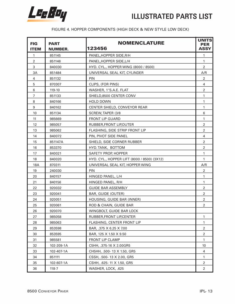
FIGITEM
UNITSPER
ASSYPART NUMBER.
NOMENCLATURE123456
1 851145 PANEL,HOPPER SIDE,R/H 1
2 851146 PANEL,HOPPER SIDE,L/H 1
3 840030 HYD. CYL., HOPPER WING (8000 / 8500) 2
3A 851484 UNIVERSAL SEAL KIT, CYLINDER A/R
4 851132 PIN 2
5 870307 CLIPS, (FOR PINS) 4
6 119-10 WASHER, 1"S.A.E. FLAT 2
7 851133 SHIELD,8500 CENTER CONV 1
8 840166 HOLD DOWN 1
9 840162 CENTER SHIELD, CONVEYOR REAR 1
10 851134 SCREW, TAPER (3/8 6
11 985669 FRONT LIP GUARD 1
12 985057 RUBBER,FRONT LIP,OUTER 2
13 985062 FLASHING, SIDE STRIP FRONT LIP 2
14 840072 PIN, PIVOT SIDE PANEL 4
15 851147A SHIELD, SIDE CORNER RUBBER 2
16 853370 HYD. TANK, BOTTOM 2
17 840021 SAFETY PROP, HOPPER 1
18 840020 HYD. CYL., HOPPER LIFT (8000 / 8500) (3X12) 1
18A 870311 UNIVERSAL SEAL KIT, HOPPER WING A/R
19 240030 PIN 2
20 840157 HINGED PANEL, L/H 1
21 840156 HINGED PANEL, R/H 1
22 920032 GUIDE BAR ASSEMBLY 2
23 920041 BAR, GUIDE (OUTER) 2
24 920051 HOUSING, GUIDE BAR (INNER) 2
25 920061 ROD & CHAIN, GUIDE BAR 2
26 920070 WINGBOLT, GUIDE BAR LOCK
27 985058 RUBBER,FRONT LIP,CENTER 1
28 985063 FLASHING, CENTER FRONT LIP 1
29 853598 BAR, .375 X 6.25 X 7.00 2
30 853595 BAR, 125 X 1.50 X 9.50 2
31 985581 FRONT LIP CLAMP 1
32 102-209-1A C5HH, .375-16 X 2.00GR5 10
33 102-407-1A CH5HH, .500- 13 X 1.50, GR5 4
34 851111 CSSH, .500- 13 X 2.00, GR5 1
35 102-607-1A CSHH, .625- 11 X 1.50, GR5 2
36 118-7 WASHER, LOCK, .625 2
IILLLLUUSSTTRRAATTEEDD PPAARRTTSS LLIISSTT
IPL- 138500 CONVEYOR PAVER
FIGURE 4. HOPPER COMPONENTS (HIGH DECK & NEW STYLE LOW DECK)

37 177-5 NUT, HEX, HEAVY, .500-13 4
38 118-5 WASHER, LOCK, .500 4
39 119-5 WASHER, FLAT, SAE, .500 4
40 119-3 WASHER, FLAT, SAE, .375 20
41 143-3 NUT, LOCK, .375-16 10
FIGITEM
UNITSPER
ASSYPART NUMBER.
NOMENCLATURE123456
IILLLLUUSSTTRRAATTEEDD PPAARRTTSS LLIISSTT
IPL- 158500 CONVEYOR PAVER
FIGURE 4. HOPPER COMPONENTS (HIGH DECK & NEW STYLE LOW DECK) CONT.

8500 CONVEYOR PAVERIPL- 16
�
��
���
��
�
��
�
��
��
�����
�����
��
��
��
��
��
���
�
��� �
��
��
��
��
��
FIGURE 5. AUGER ASSEMBLY
IILLLLUUSSTTRRAATTEEDD PPAARRTTSS LLIISSTT

1 860010 HYD. MOTOR, AUGER (ALL) / CONVEYOR (8000B) 2
2 860030 SPROCKET, AUGER DRIVE MOTOR (8000 / 8500) 2
3 860021 MOUNTING BRACKET, AUGER MOTOR 2
4 860090 CHAIN, PAVER AUGER DRIVE 2
4A 860049 MASTER LINK (60H) A/R
5 861130C SHAFT W/ SPROCKET, CASTED AUGER 2
6 860043 COVER, AUGER CHAIN DRIVE (8000 / 8500) 1
7 851645 COLLAR, RETAINING CAP WITH BOLT 1
8 810070 BUSHING, TRACK IDLER / TRUCK HITCH 1
9 860051HDR ENDMOUNT, R.H. AUGER 1
9A 860051HDL ENDMOUNT, L.H. AUGER 1
10 851647 END CAP, FOR AUGER
11 851645-1 SET SCREWS A/R
12 860043-1 KIT, AUGER COVER CLOSING A/R
13 860136 AUGER EXTENSION, R.H. A/R
13A 860135 AUGER EXTENSION, L.H. A/R
14 140610 GREASE FITTING A/R
15 850130 BEARING 2
16 861140C AUGER SECTION, R.H. 4
17 860083 AUGER ASSEMBLY,R.H. 1
18 861150C AUGER SECTION, L.H. 4
19 860073 AUGER ASSEMBLY, L.H. A/R
20 861141 BOLT AND NUT, CASTED AUGER A/R
21 860035 SPROCKET, AUGER SHAFT ( WELD ON) 2
22 860012 SEAL KIT, HYD. MOTOR 2
23 853403 CENTER AUGER SUPPORT A/R
24 853410 AUGER COVER, BOTTOM A/R
FIGITEM
UNITSPER
ASSYPART NUMBER.
NOMENCLATURE123456
IILLLLUUSSTTRRAATTEEDD PPAARRTTSS LLIISSTT
IPL- 178500 CONVEYOR PAVER
FIGURE 5. AUGER ASSEMBLY

8500 CONVEYOR PAVERIPL- 18
���
�
�
�
�
�
����
���
�
����
����
�� ����
�
�
��
�
�
��
��
������
����
��
��
FIGURE 6. CONVEYOR DRIVE CUTOFF, SCREED LIFT CYLINDERS
IILLLLUUSSTTRRAATTEEDD PPAARRTTSS LLIISSTT

FIGITEM
UNITSPER
ASSYPART NUMBER.
NOMENCLATURE123456
1 260130 HYDRAULIC MOTOR 2
2 851148 BOLT, CONVEYOR DRIVE CHAIN ADJUSTER 4
3 851149 MOUNT, CONVEYOR DRIVE MOTOR 2
4 851121 CHAIN, CONVEYOR DRIVE (#80) 2
5 851120 SPROCKET, CONVEYOR DRIVE MOTOR 2
6 851111 CAP SCREW, 1/2"-13 x2"HEX HEAD 8
7 116-5 NUT, 1/2"-13 HEX 8
8 851151L CHAINGUARD, CONVEYOR L.H. DRIVE 1
8A 851151R CHAINGUARD, CONVEYOR R.H. DRIVE 1
9 930039 COTTER PIN, 3/16" X 2" LONG 4
10 118-3 WASHER, 3/8" LOCK 6
11 102-203-1A CAP SCREW, 3/8"-16 x 3/4"HEX HEAD 6
12 851436 HYD. CYL., SCREED LIFT (1000C / 8000C / 8500) 2
13 118-10 WASHER, 1" LOCK 2
14 100-913-1A CAP SCREW, 1"-14x3 GR. 8 HEX HEAD 2
15 142-10 LOCK NUT, 1"-14 HEX 2
16 100-915-1A CAP SCREW, 1'-14x3 1/2", GR.8 HEX HEAD 2
17 851152 PLATE, CUTOFF CYLINDER MOUNT 2
18 102-607-1A CAP SCREW, 5/8"-11x1 1/2" HEX HEAD 6
19 118-7 WASHER, 5/8" LOCK 6
20 240030 PIN, HYDRAULIC CYLINDER 2
21 910170 HYD. CYL., CUTOFF 2
22 851153 CUT-OFF LEFT SIDE 1
23 851154 CUT-OFF RIGHT SIDE 1
24 102-5-1A CAP SCREW, 1/4"-20x 1" HEX HEAD 2
25 118-1 WASHER, 1/4" LOCK 2
26 860036 WASHER, FENDER (1/4 2
27 102-114-1A CAP SCREW, 5/16"-18 x 3 1/2" 4
28 119-2 WASHER, 5/16" FLAT 4
29 118-2 WASHER, 5/16" LOCK 4
30 116-2 NUT, 5/16"-18 HEX 4
31 850001 MANIFOLD ASSEMBLY, AUGERS AND 2- SPEED 1
33 851237A COIL, WITH DIODE, 12 V SINGLE TERMINAL (AUGERS& 2 SPEED) A/R
34 856781 WEAR PLATE, AUGER BACK A/R
NOTE: WHEN ORDERING COILS ALWAYS RECORD MANIFOLD BLOCK
NUMBER: IE: 8500-01-A OR 8500-01-F
IILLLLUUSSTTRRAATTEEDD PPAARRTTSS LLIISSTT
IPL- 198500 CONVEYOR PAVER
FIGURE 6. CONVEYOR DRIVE CUTOFF, SCREED LIFT CYLINDERS

8500 CONVEYOR PAVERIPL- 20
����
�
�
�
�
�
�
�
��
��
����
��
��
��
���
�
FIGURE 7. HYDRAULIC COMPONENTS L/H SIDE
IILLLLUUSSTTRRAATTEEDD PPAARRTTSS LLIISSTT

1 851232 TANK, HYDRAULIC (TOP HIGH DECK) 1
1A 851233 TANK, HYDRAULIC (TOP LOW DECK) N/S 1
2 140030GK STRAINER & GASKET KIT 1
3 140030HL CAP, HYD. TANK (LOCKABLE) 1
4 910129 ADAPTER, 1/4" MPT x 1/4" MJIC (90 DEGREE) 1
5 851234 HOSE, VENT 1
6 910150 PETCOCK, HYD. OIL LEVEL 1
7 330040 GAUGE, TACK TEMP/ HYD. OIL TEMP. 1
8 910120 VALVE, MONOBLOCK (CONVEYOR/ WINGS) 1
9 910130 HANDLE, MONOBLOCK VALVE (CONVEYOR WINGS) 1
10 910122 MANIFOLD, SIDE WING 1
11 910122-1 RELIEF VALVE, SIDE WING MANIFOLD 1
16 851628 MANIFOLD, AUTO CONVEYOR (WATERMAN) 1
21 851628A MANIFOLD, AUTO CONVEYOR (H.P.S.) 1
22 851628A-1 CARTRIDGE VALVE, AUTO CONVEYOR (H.P.S.) 1
23 851628A-2 COIL, 12V (H.P.S.) 2
24 851628A-3 NUT, COIL(H.P.S.) 2
25 850001 MANIFOLD, AUTO AUGER/ 2-SPEED (H.P.S.) 1
26 851235 CARTRIDGE VALVE, AUTO AUGER (H.P.S.) 2
*26A 850004 CARTRIDGE VALVE, AUTO AUGER (WATERMAN) 2
27 851236 CARTRIDGE VALVE, 2-SPEED (H.P.S.) 1
*27A 850003 CARTRIDGE VALVE, 2-SPEED 1
28 851237A COIL, W/ DIODE,12V 3
28A 850005 COIL, W/ DIODE,12V (WATERMAN) 3
*NOTE: OLD STYLE
FIGITEM
UNITSPER
ASSYPART NUMBER.
NOMENCLATURE123456
IILLLLUUSSTTRRAATTEEDD PPAARRTTSS LLIISSTT
IPL- 218500 CONVEYOR PAVER
FIGURE 7. HYDRAULIC COMPONENTS L/H SIDE

8500 CONVEYOR PAVERIPL- 22
�����
�
��
������
����
��
��
��
����
� ��
��
��
������
��
���� ��
��
����
����
��
����
������
�� � �
�
�
�� �
��
��
���
���
��
�
��
�
��
FIGURE 8. SPECIAL COMPONENTS L/H SIDE WITH TST DASH
IILLLLUUSSTTRRAATTEEDD PPAARRTTSS LLIISSTT

FIGITEM
UNITSPER
ASSYPART NUMBER.
NOMENCLATURE123456
1 943309 GAUGE, VOLT METER 1
2 943306 GAUGE, FUEL LEVEL 1
2A 134318 SENDING UNIT (NS) 1
3 943270 GAUGE, OIL PRESSURE 1
3A 127353 SENDING UNIT 1
4 5120-1200 HOUR-METER 1
5 900030 TOGGLE SWITCH, AUTO CONVEYOR 2
6 500040 TOGGLE SWITCH, ON-OFF A/R
7 320380 KEY, HATZ ENGINE
8 320386 INDICATOR LIGHT, BATTERY, (WITHOUT BULB)
9 320370 COVER, IGNITION SWITCH (HATZ) 1
11 920161 CABLE, THROTTLE 1
12 920165 DASH, COMPLETE 8500/8000D 1
17 920130 CABLE, R.H. CONTROL (123" X 3" STROKE) 1
18 920130 CABLE, R.H. CONTROL (123" X 3" STROKE) 1
19 920120 CABLE, R.H. DRIVE, AUGER & PUMP (104" X 3") 2
20 920090 SPHERICAL ROD END, W / STUD 4
21 920092 NUT, 3/8"-24 HEX 4
22 920094 R.H. PIVOT, FOR.& REV. LEVER (LEFT SIDE) 1
23 920096 L.H. PIVOT, FOR.& REV.LEVER (LEFT SIDE) 1
24 920097 HANDLE, DRIVE 2
25 116-5-1 NUTS, JAM 1/2" 2
26 920225 KNOB, ROUND BALL (1 7/8" X 1/2"-13 THREADS) 4
27 119-7 WASHER, FLAT, 5/8" 2
28 490080 WASHER, BEVEL 2
29 920229 CAPSCREW,5/8"-11x7 1/2" 1
30 116-7-1 NUT, 5/8"-11 HEX JAM 2
31 900713 U-BOLTS, 3/8" 6
32 350050 CLEVIS, YOKE 2
33 350080 PIN, CLEVIS 2
34 850100 PIN, COTTER 2
35 920233 ADAPTER, 1/2"M.P.T.x #8 MALE SAE. 1
36 910080 VALVE, VIBRATOR 1
37 920234 SHIELD 1
38 102-1091A CAPSCREW, 5/16"-18x201/4"
39 920238 CONTROL, REMOTE (ELECTRIC FLIGHT SCREW) 1
40 900020 SWITCH, NEUTRAL SAFETY 1
41 900029 BRACKET, SAFETY SWITCH 1
IILLLLUUSSTTRRAATTEEDD PPAARRTTSS LLIISSTT
IPL- 238500 CONVEYOR PAVER
FIGURE 8. SPECIAL COMPONENTS L/H SIDE WITH TST DASH

42 900080 SWITCH, REMOTE (ONLY) 1
43 900082 CORD, REMOTE 1
44 920136 CABLE, DRIVE/ EXTENSION 2
45 116-3-1 NUT, 3/8"-16 HEX JAM 1
46 851156 KNOB. 1
47 320330 SOCKET, RELAY 1
48 118-C WASHER, #6 LOCK 2
49 110-125-4 SCREW, # 6-32 x1" PHILLIPS HEAD 2
50 116-1 NUT, 1/4"-20 HEX 2
51 118-1 WASHER, LOCK, 5/16" 2
52 102-3-1A CAPSCREW, 1/4"-20 x 3/4" 2
FIGITEM
UNITSPER
ASSYPART NUMBER.
NOMENCLATURE123456
IILLLLUUSSTTRRAATTEEDD PPAARRTTSS LLIISSTT
IPL- 258500 CONVEYOR PAVER
FIGURE 8. SPECIAL COMPONENTS L/H SIDE WITH TST DASH CONT.

8500 CONVEYOR PAVERIPL- 26
���
��
��
����
�
��
���
��
��
�� ���
�� �
����
�
�
�
�
�
�
��
�
FIGURE 9. R/H DRIVE & FUEL TANK
IILLLLUUSSTTRRAATTEEDD PPAARRTTSS LLIISSTT

1 851157 TANK, HIGH DECK FUEL 1
1A 851642 TANK, FUEL LOW DECK 20G 1
2 140030FL FUEL TANK CAP, LOCKABLE 1
3 920140 CABLE, R.H. DRIVE / CONTROL (116" X 3" STROKE 2
4 350060 U-BOLT, 3/8" 4
5 920140 CABLE, R.H. DRIVE / CONTROL (116" X 3" STROKE 1
6 920140 CABLE, R.H. DRIVE / CONTROL (116" X 3" STROKE 1
7 920072 LOCK WASHER, 3/8" 2
8 920093 NUT, HEX 3/8" 2
9 350080 PIN, CLEVIS 1/4" 2
10 960019 PIN, COTTER 2
11 920228 HANDLE, DRIVE L/H (LEE-BOY) 1
12 920230 HANDLE, (R/H) (LEE-BOY) 1
13 920145 ROD FOR RIGHT HAND 5/8 1
14 119-7 LOCKWASHER, 5/8" 1
15 116-7-1 NUTS, JAM (5/8 2
16 350054 PIVOT, HANDLE 2
17 920210 CASTED HANDLE, R.H. CONTROL 2
18 920090 SPHERICAL ROD END, W / STUD 2
19 350050 CLEVIS, 1/4" 2
20 920225 KNOB, ROUND BALL (1 7/8" X 1/2"-13 THREADS) 2
21 116-5 NUT, HEX 1/2"
FIGITEM
UNITSPER
ASSYPART NUMBER.
NOMENCLATURE123456
IILLLLUUSSTTRRAATTEEDD PPAARRTTSS LLIISSTT
IPL- 278500 CONVEYOR PAVER
FIGURE 9. R/H DRIVE & FUEL TANK

8500 CONVEYOR PAVERIPL- 28
�
�
��
�
��
��
����
��
��
��� �
����
����
��
����
�� ���� ������
�
�
��
�
��
��
�
��
FIGURE 10. PUMP COMPONENTS SUNDSTRAND
IILLLLUUSSTTRRAATTEEDD PPAARRTTSS LLIISSTT

1 851479 PUMP DRIVE PLATE, FLYWHEEL 1
2 320200 COVER, PUMP PLATE 1
3 320224 BRACE, PUMP SUNDSTRAND 1
4 320142 WASHER, LOCK 1
5 320227 CAPSCREW 2
6 320228 CAPSCREW 2
7 320229 WASHER, LOCK 2
8 851160-1 DRIVE CPLG. CHARGE PUMP 1
9 320235 O-RING, (PIGGYBACK TO MAIN PUMP) 1
10 851160A HIGH VOLUMN PUMP, AUGERS AND CONVEYORS 1
11 320416 PUMP, L.&R. DRIVE SUN STRAND 1
12 851495A SHAFT, NEW STYLE (NOTE: SEAL SIZE 2 7/8"OUTSIDE ) 1
12A 851495 SHAFT, OLD STYLE ( NOTE: SEAL SIZE 1 5/8" OUTSIDE)
13 851489 SEAL, FRONT SUNDSTRAND ( NOTE: 1 5/8"OUTSIDE) 1
13A 851489A SEAL, NEW STYLE FRONT SUNDSTRAND ( NOTE: 2 7/8" OUTSIDE)
14 320242 WASHER 2
15 320243 CAPSCREW 2
16 320245 ARM, LEFT DRIVE 1
17 900025 ARM, RIGHT DRIVE 1
18 900027 NUT 2
19 920090 SPHERICAL ROD END, W / STUD 2
20 920120 CABLE, R.H. DRIVE, AUGER & PUMP (104" X 3") 2
21 350060 U-BOLT, 3/8" 2
22 920125 BRACKET, PUMP CABLES 1
23 320142 WASHER, LOCK 2
24 320227 CAPSCREW 2
25 851160-2 DRIVE CPLG, TANDEM PUMP 1
26 851504 BACKUP ALARM, PRESSURE SWITCH 1
27 320244 SOLENOID, NEUTRAL PAUSE 1
28 320244K SOLENOID, NEUTRAL PAUSE (KIT) A/R
FIGITEM
UNITSPER
ASSYPART NUMBER.
NOMENCLATURE123456
IILLLLUUSSTTRRAATTEEDD PPAARRTTSS LLIISSTT
IPL- 298500 CONVEYOR PAVER
FIGURE 10. PUMP COMPONENTS SUNDSTRAND

8500 CONVEYOR PAVERIPL- 30
�
�
�
��
�
�
�
�
�
�
�
��
��
��
��
��
FIGURE 11. PUMP COMPONENTSSUND STRAND ELECTRONIC STEERING
IILLLLUUSSTTRRAATTEEDD PPAARRTTSS LLIISSTT

1 851666 KNOB, JOYSTICK 1
2 851667 DECAL, STEERING DASH 1
3 851538 BOOT, JOYSTICK 1
4 851540 POTENTIOMETER, STEERING 1
5 851537 JOYSTICK ASSEMBLY A/R
6 851535 SWITCHES, SAFETY NEUTRAL A/R
7 851667 DECAL, STEERING KNOB A/R
8 850670 KNOB, STEERING 1
9 851546 STEERING BOX, SUNDSTRAND 1
10 851548 CURLY CORD, STEERING BOX TO JUNCTION BOX 1
11 851553 WIRE HARNESS, JUNCTION BOX TO CONTROLLER 1
12 851545-1 CONTROLLER, E.D.C. 1
13 851549 JUNCTION BOX, SUNDSTRAND 1
14 851547 MC. MICRO CONTROLLER 1
14A 852410 MC. MICRO CONTROLLER (USE WITH REX ROTH PUMPS)
15 851160-A TANDEM AUXILIARY PUMP, AUGERS & CONVEYORS 1
16 851545 HYD.PUMP, TANDEM PROPULSION (W/E.D.C.) (SUNSTRAND) 1
16A 851525 HYDROLIC PUMP TANDOM (REX ROTH) DEN CONNECTOR
16B 985663 HYDROLIC PUMP TANDOM (REX ROTH)
17 500040 TOGGLE SWITCH, ON / OFF 1
FIGITEM
UNITSPER
ASSYPART NUMBER.
NOMENCLATURE123456
IILLLLUUSSTTRRAATTEEDD PPAARRTTSS LLIISSTT
IPL- 318500 CONVEYOR PAVER
FIGURE 11. PUMP COMPONENTSSUND STRAND ELECTRONIC STEERING
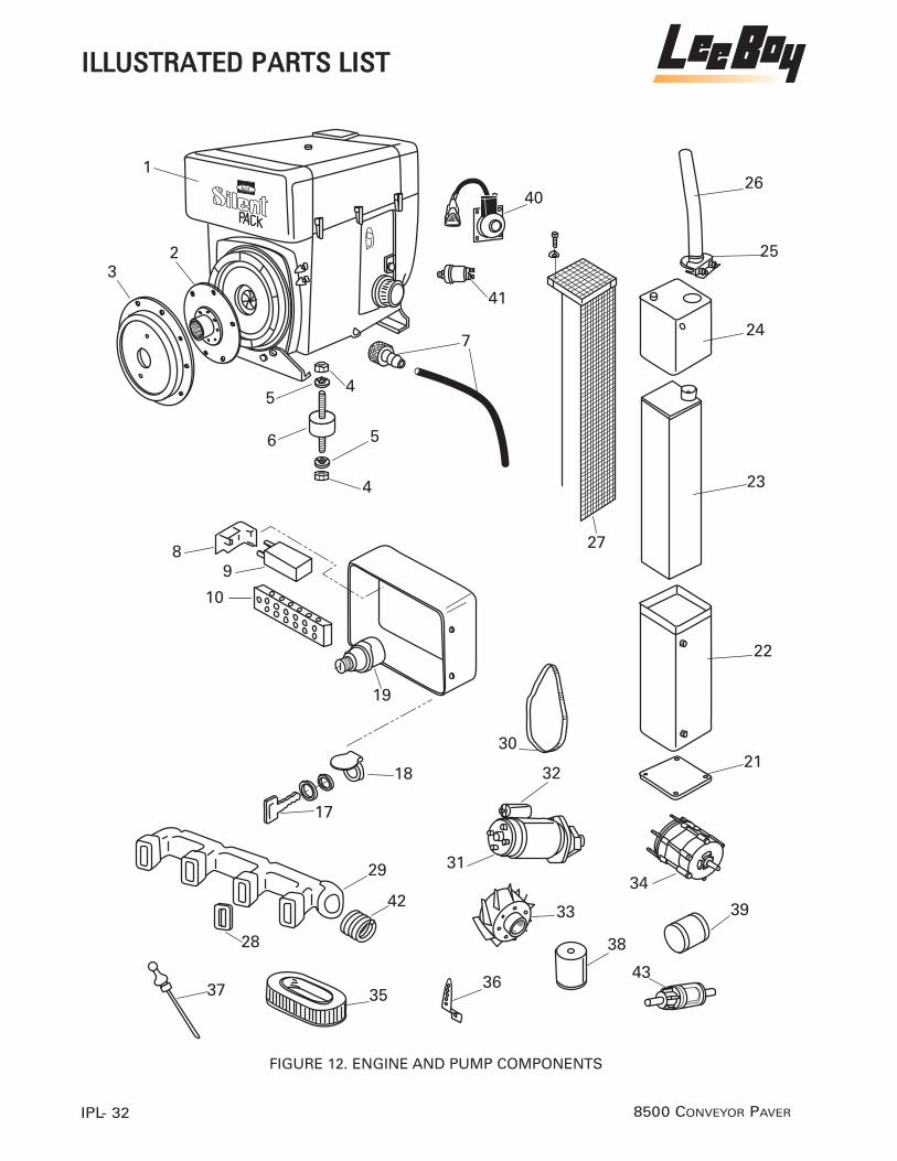
8500 CONVEYOR PAVERIPL- 32
��
��
��
��
��
�
�
�
�
��
��
��
����
��
��
��
����
��
��
�
�
��
��
��
��
��
��
��
��
��
FIGURE 12. ENGINE AND PUMP COMPONENTS
IILLLLUUSSTTRRAATTEEDD PPAARRTTSS LLIISSTT

FIGITEM
UNITSPER
ASSYPART NUMBER.
NOMENCLATURE123456
1 320001 4 CYL. DIESEL ENG., HATZ 4L41C (SILENT-PAK) 1
2 851479 PUMP DRIVE PLATE, FLYWHEEL 2
3 320200 COVER, PUMP PLATE 1
4 320144 NUT,10mm. 1
5 320142 WASHER, 10mm. 4
6 320140 MOUNTPAD, ENGINE HATZ 4
7 851497 HOSE & DRAIN FITTING, ENGINE OIL DRAIN 1
8 320330 MOUNT, STARTER RELAY 1
9 320320 RELAY, STARTER 1
10 320340 BLOCK, TERMINAL 1
11 320383 INDICATOR LAMP, ENGINE TEMP NS
12 320385 INDICATOR LAMP, AIR FILTER NS
13 320384 INDICATOR LIGHT, ENG.OIL PRESS. NS
14 320386 INDICATOR LIGHT, BATTERY CHARGE NS
15 320360 LIGHT BULB, INDICATOR LAMP NS
16 320382 PLUGS NS
17 320380 IGNITION KEY, HATZ DIESEL 1
18 320381 FLAP, IGNITION SWITCH 1
19 320390 IGNITION SWITCH, HATZ DIESEL 1
21 HATO3878000 PLATE, MUFFLER BOTTOM 1
22 HATOO871801 COVER, MUFFLER BOTTOM 1
23 320422 MUFFLER, HATZ SILENT PACK 1
24 HATO1083000 COVER, MUFFLER TOP 1
25 320030 CLAMP, 2" EXH. PIPE 1
26 851164 PIPE EXT. MUFFLER 1
27 320510 HEAT SHIELD, MUFFLER 1
28 320260 GASKET, EXH. MANIFOLD TO CYL. HEAD 3
29 320250-4 EXH. MANIFOLD, HATZ 4 CYL. 1
30 320090 BELT, ALTERNATOR / BLOWER 1
31 320270 STARTER MOTOR 1
32 320280 SOLENOID, STARTER 1
33 320290 BLOWER FAN 1
34 985010 ALTERNATOR, 12 VOLT 1
35 310060 ELEMENT, AIR FILTER 2
36 320120 LEVER, ENGINE THROTTLE 1
37 320110 DIPSTICK, ENGINE OIL LEVEL 1
38 310080 ELEMENT, FUEL FILTER 1
39 310070 ELEMENT, OIL FILTER 1
IILLLLUUSSTTRRAATTEEDD PPAARRTTSS LLIISSTT
IPL- 338500 CONVEYOR PAVER
FIGURE 12. ENGINE AND PUMP COMPONENTS

40 851567 SOLENOID, FUEL SHUT-OFF 1
41 853490 SENDING UNIT, OIL PRESSURE 1
42 HATO01603700 GASKET, MUFFLER TO MANIFOLD 1
43 310090 IN-LINE FUEL FILTER 1
FIGITEM
UNITSPER
ASSYPART NUMBER.
NOMENCLATURE123456
IILLLLUUSSTTRRAATTEEDD PPAARRTTSS LLIISSTT
IPL- 358500 CONVEYOR PAVER
FIGURE 12. ENGINE AND PUMP COMPONENTS CONT.

8500 CONVEYOR PAVERIPL- 36
���� ��
�
�
�
������������������������
�
��
�
�
��
��
��
���
�
��
��
��
��
��
��
���������
�
��
FIGURE 13. MAIN VALVE AND SPRAY DOWN
IILLLLUUSSTTRRAATTEEDD PPAARRTTSS LLIISSTT

1 851161 VALVE, MAIN 1
2 910060A HANDLE, VERTICAL 8
3 910060 HANDLE, HORIZONTAL 1
4 901009 VALVE, RELIEF 1
5 910052 SECTION,VALVE (AUGERS) (DETENTED) 2
6 910054 SECTION, VALVE (CYLINDERS) (SPRING RETURN) 6
7 910055 INLET COVER, V-20 (W/RELIEF) 1
8 910056 OUTLET COVER, V-20 (W/PB SLEEVE) 1
9 350080 PIN, CLEVIS (1/4”) 8
10 901010 LINK ASSY., VALVE LEVER 8
11 901010 COTTER PIN 8
12 910058 BRACKET, VALVE LEVER 8
13 910054FLS FLOAT, ASSEMBLY SCREED 1
14 920200 HOSE REEL, MACHINE WASHDOWN 1
15 900010 PUMP, SPRAYDOWN (FLOWJET) 1
16 480260 BRACKET, WATER / FUEL PUMP MOUNT 1
17 920222 TEE, 3/8” 1
18 920223 NIPPLE, 3/8” 1
19 920221 HOSE, PUMP TO HOSE REEL 1
20 920220A HANDLE & NOZZLE, FUEL WASH-DOWN 2
21 920220 HANDLE & NOZZLE, FUEL WASH-DOWN 2
22 901210A NOZZLE, FUEL WASH-DOWN HANDLE A/R
23 920224 HOSE, TO SPRAYDOWN HANDLE 2
24 850101 TAB, AUGER LOCKOUT
25 851448 PRESSURE SWITCH (FLOWJET PUMP) A/R
SEAL KITS FOR VALVES
910059 SEAL KIT, VALVE SPOOL
910062 SEAL KIT, VALVE SECTION
910065 KIT, SEAL (RELIEF VALVE)
FIGITEM
UNITSPER
ASSYPART NUMBER.
NOMENCLATURE123456
IILLLLUUSSTTRRAATTEEDD PPAARRTTSS LLIISSTT
IPL- 378500 CONVEYOR PAVER
FIGURE 13. MAIN VALVE AND SPRAY DOWN

8500 CONVEYOR PAVERIPL- 38
�
��
��
�
�
���� �!�����
��
�
�
�
��
�
����
��
��
����
�
�
�
�
�
���"���#���������!�����"�$�%
FIGURE 14. FILTER LOCATION & ACCESSORIES (HATZ)
IILLLLUUSSTTRRAATTEEDD PPAARRTTSS LLIISSTT

FIGITEM
UNITSPER
ASSYPART NUMBER.
NOMENCLATURE123456
1 310080 ELEMENT, FUEL FILTER (HATZ DIESEL) 1
2 920161 CABLE, THROTTLE 1
3 350050 CLEVIS, 1/4" 1
4 350080 PIN, CLEVIS (1/4) 1
5 960019 PIN, COTTER (1/4) 1
6 320120 LEVER, THROTTLE 1
7 290010 HEAD, CHARGE / RETURN FILTER 1
8 290030 ELEMENT, CHARGE / RETURN FILTER 1
9 102-205-1A CAPSCREW, 3/8X1" 4
10 118-3 WASHER, 3/8" 4
15 851400 HYD. OIL COOLER, W / FAN, MOTOR & SENSOR 1
16 900050 MIRCO SWITCH, AUTO. CONVEYORS 2
17 900060 ARM, AUTO. CONVEYOR SWITCH 2
18 900075 LINKAGE 2
19 900076 SCREWS 2
20 900077 LOCK WASHER 2
21 900078 NUT 2
22 900079 PIN, COTTER (1/4) 2
23 310060 ELEMENT, AIR FILTER (HATZ DIESEL) 2
24 320500 COVER,ENGINE ACCESS(HATZ 4L41C 1
25 851163 SHIELD, HEAT 4 CYLINDER (HATZ) 1
26 310070 OIL FILTER, HATZ 1
IILLLLUUSSTTRRAATTEEDD PPAARRTTSS LLIISSTT
IPL- 398500 CONVEYOR PAVER
FIGURE 14. FILTER LOCATION & ACCESSORIES (HATZ)

8500 CONVEYOR PAVERIPL- 40
�
���
�
�
����
�
�������
��
�
���
����
����
�
����
������
�
�� ��
�
��
��
��
FIGURE 15. SEAT, WALKWAY & OTHER COMPONENTS (HIGH DECK)
IILLLLUUSSTTRRAATTEEDD PPAARRTTSS LLIISSTT

FIGITEM
UNITSPER
ASSYPART NUMBER.
NOMENCLATURE123456
1 360010 SEAT ASSY W / ARMREST, WHITE 1
2 920024 SUPPORT, SEAT H/D 1
3 851166 BAR, INSTRUMENT SLIDE (HIGH DECK) 1
3A 851167 BAR, INSTRUMENT SLIDE (LOW DECK) 1
4 851168 WALKWAY, UPPER 1
5 851169 TOOL BOX 1
6 851170 SHIELD, WALKWAY 1
7 851171 SHIELD, PUMP LOWER 1
8 851172 SHIELD, PUMP UPPER 1
9 102-205-1A CAPSCREW, 3/8"x 1" 5
10 118-3 WASHER, LOCK 3/8" 9
11 102-205-1A CAPSCREW 3/8” - 16 x 1” HEX 2
12 116-3 NUT, HEX 3/8" 2
13 116-7-1 NUT, HEX 5/8" 2
14 102-615-1A CAPSCREW, 11 x 3 1/2" 2
15 500040 TOGGLE SWITCH, ON / OFF 2
16 920210A LEVER, SCREED EXT. REMOTE 2
17 920120 CABLE, SCREED EXTENSION 2
18 350050 CLEVIS, 1/4" 2
19 350080 PIN, CLEVIS 2
20 910057 PIN, COTTER 2
21 920120 CABLE, SCREED EXTENSION 2
22 160320 HORN, BACKUP ALARM
23 230062 BRACKET, W/CLAMP, LPG TANK MOUNT
24 982024 CITRUS TANK (Not Shown)
IILLLLUUSSTTRRAATTEEDD PPAARRTTSS LLIISSTT
IPL- 418500 CONVEYOR PAVER
FIGURE 15. SEAT, WALKWAY & OTHER COMPONENTS (HIGH DECK)

8500 CONVEYOR PAVERIPL- 42
�
�
���
�
�
��
�
�
FIGURE 16. SEAT, WALKWAY & OTHER COMPONENTS (LOW DECK)
IILLLLUUSSTTRRAATTEEDD PPAARRTTSS LLIISSTT

FIGITEM
UNITSPER
ASSYPART NUMBER.
NOMENCLATURE123456
1 851173 BAR, SEAT SLIDE 1
2 102-415-1A CAPSCREW 1/2 - 13 x 31/2” 2
3 118-5 WASHER, LOCK 1/2 2
4 115-5-A NUT, HEX 1/2 2
5 851176L WALKWAY, LOWER (STEP) LEFT SIDE 2
5 851176R WALKWAY, LOWER (STEP) RIGHT SIDE 2
6 102-206-1A CAPSCREW 3/8 - 16 - 1 1/4” 4
7 118-3 WASHER, LOCK 3/8 4
8 920024 SUPPORT, SEAT H/D 1
9 360010 SEAT ASSY. W/ARMREST, WHITE 1
10 851175 WALKWAY, UPPER (STEP) 1
11 851174 HOLDER, SEAT 1
IILLLLUUSSTTRRAATTEEDD PPAARRTTSS LLIISSTT
IPL- 438500 CONVEYOR PAVER
FIGURE 16. SEAT, WALKWAY & OTHER COMPONENTS (LOW DECK)

8500 CONVEYOR PAVERIPL- 44
�� �� ����
���
��
����
���
���
��
����
��
�
����
� ����
��
�����
���
���
��
��
�
�
���
� ���
��
�����
��
����
��
��
��
���"����#����������!�����"�$�%
��
��
��
FIGURE 17. EXPANDABLE SCREED ASSEMBLY (PART I)
IILLLLUUSSTTRRAATTEEDD PPAARRTTSS LLIISSTT

FIGITEM
UNITSPER
ASSYPART NUMBER.
NOMENCLATURE123456
982971 SCREED, COMPLETE
1 982797 SCREED BASE, NEW STYLE 1
2 851179 BUSHING, SCREED EXTENSION (3" LONG) 1
3 851180 GUARD, HOUSING SPECIFY (L/H OR R/H) 1
4 851181L EXTENSION, UPPER, LEFT SIDE 1
5 851182L WEAR PLATE, L.H. SCREED EXT. (C & D SCREED) 1
5A 851182R WEAR PLATE, R.H. SCREED EXT. (C & D SCREED) 1
6 851183 COUPLING, MALE 1
7 851184 ADJUSTING SCREW, SCREED EXTENSION 2
9 870030 BEARING, SCREED FLIGHT SCREW 2
10 851186 SPACER 1
11 116-8 NUT, HEX 3/4" 1
12 870279 CAPSCREW, SOCKET HEAD SHOULDER 1
13 143-3 LOCKNUT, 3/8"-16 1
14 102-309-1A CAPSCREW, 7/16"x2" HEX HEAD 1
15 119-4 WASHER, FLAT, 7/16" 1
16 851256 SNAPRING 2
17 851188 SHAFT, EXTENSION 2
18 851179 BUSHING, SCREED EXTENSION (3" LONG) 2
19 851190 SLIDE, INNER EXTENSION 1
20 100-408-1 CAPSCREW, 1/2"x20x1 1/2" HEX HEAD 2
21 118-5 WASHER, 1/2" LOCK 2
22 119-5 WASHER, 1/2" FLAT 2
23 851191 HYD. CYL., SCREED EXT. (L.H.) 1
23A 851484 UNIVERSAL SEAL KIT
23 851192 HYD. CYL., SCREED EXTENSION (R.H.) 1
24 860048 CAPSCREW, 7/16"x2" HEX HEAD 2
25 210060 PIN, CYLINDER 2
26 118-4 WASHER, 5/8" FLAT 2
27 983405 MOTOR, HYDRAULIC SCREED VIBRATOR (8515) 1
28 102-606-1A CAPSCREW, 5/8"-11x1 1/4" HEX HEAD 2
29 118-7 WASHER, 5/8" LOCK 2
30 119-7 WASHER, 5/8" FLAT 2
31 870232 VIBRATOR, SCREED 1
32 870172 TURN BUCKLE, CROWN & VALLEY (FRONT) 1
33 870190 CHAIN, CROWN & VALLEY #40 1
34 870182 TURN BUCKLE, CROWN & VALLEY (REAR) 1
35 851195 HANDLE, CRANK 1
IILLLLUUSSTTRRAATTEEDD PPAARRTTSS LLIISSTT
IPL- 458500 CONVEYOR PAVER
FIGURE 17. EXPANDABLE SCREED ASSEMBLY (PART I)

FIGITEM
UNITSPER
ASSYPART NUMBER.
NOMENCLATURE123456
IILLLLUUSSTTRRAATTEEDD PPAARRTTSS LLIISSTT
IPL- 478500 CONVEYOR PAVER
FIGURE 17. EXPANDABLE SCREED ASSEMBLY (PART I) CONT.
36 102-607-1A CAPSCREW, 5/8"x 1 1/2" 2
37 118-7 WASHER, 5/8" LOCK 2
38 119-7 WASHER, 5/8" FLAT 2
39 851299 GUIDE, EXTENSION LOWER, (WELDMENT) 2
40 851298 GUIDE, EXTENSION TOP 1
41 102-406-1A CAPSCREW, 1/2"x 1 1/4" 2
42 118-5 WASHER, LOCK 1/2" 2
43 119-7 WASHER, FLAT, 1/2" 2
44 851196 PIN, SCREED EXTENSION HINGE 1
45 119-4 WASHER, FLAT, 7/16" 2
46 116-5 NUT, 7/16" 2
47 851600-1 BURNER PIPE EXTENSION
48 851197-1 BURNER PIPE, MAIN

8500 CONVEYOR PAVERIPL- 48
�
��
�
��
��
��
����
�
�
���
�
FIGURE 18. EXPANDABLE SCREED ASSEMBLY (PART II)
IILLLLUUSSTTRRAATTEEDD PPAARRTTSS LLIISSTT

FIGITEM
UNITSPER
ASSYPART NUMBER.
NOMENCLATURE123456
1 982797 SCREED, BASE (NEW STYLE) 1
2 851198 STEP, UPPER 2
3 851199 BULKHEAD, HYDRAULIC 1
4 851134 CAPSCREW, HEX, 3/8"x3/4" 20
5 118-3 WASHER,LOCK 3/8" 20
6 981724 PLATE, SCREED (NEW STYLE WEAR PLATE WITH 90 ANGLE AT FRONT)
(Serial #40383 and up)
7 851201 LID, SCREED 2
8 851202 GROMMET 1
9 851203 COVER, CYLINDER (R/H) 1
10 851204 COVER, CYLINDER (L/H) 1
11 856733L WALKBOARD ASSEMBLY, ELITE 3 LOWER LEFT HAND (NS) 1
11A 856733R WALKBOARD ASSEMBLY, ELITE 3 LOWER RIGHT HAND (NS) 1
12 121-3 WASHER, WEDGE 20
13 851370 FLIGHT SCREW ASSEMBLY 2
14 870276 GRIP, HANDLE 2
*15 851372 ROD GAUGE 1
*16 870030 BEARING, SCREED FLIGHT SCREW 1
*17 851373 LOCK, ARM 1
* ITEMS NOT INCLUDED WITH PART. NO. 851370
FLIGHT SCREW ASSEMBLY
IILLLLUUSSTTRRAATTEEDD PPAARRTTSS LLIISSTT
IPL- 498500 CONVEYOR PAVER
FIGURE 18. EXPANDABLE SCREED ASSEMBLY (PART II)

8500 CONVEYOR PAVERIPL- 50
�
�
�
�
�
FIGURE 19. VIBRATOR ASSEMBLY
IILLLLUUSSTTRRAATTEEDD PPAARRTTSS LLIISSTT

FIGITEM
UNITSPER
ASSYPART NUMBER.
NOMENCLATURE123456
1 280030 COUPLING HALF, TACK PUMP MOTOR 1
2 280040 INSERT, 3-JAW COUPLING 1
3 880030 COUPLING HALF, 1" (VIBRATOR SHAFT) 1
4 880042 HOUSING, VIBRATOR ECCENTRIC 1
5 250150 BEARING, CONVEYOR PULLEY/ VIBRATOR SHAFT 2
6 880062 SHAFT, VIBRATOR ECCENTRIC 1
7 880071 PLATE, VIBRATOR HOUSING 1
IILLLLUUSSTTRRAATTEEDD PPAARRTTSS LLIISSTT
IPL- 518500 CONVEYOR PAVER
FIGURE 19. VIBRATOR ASSEMBLY
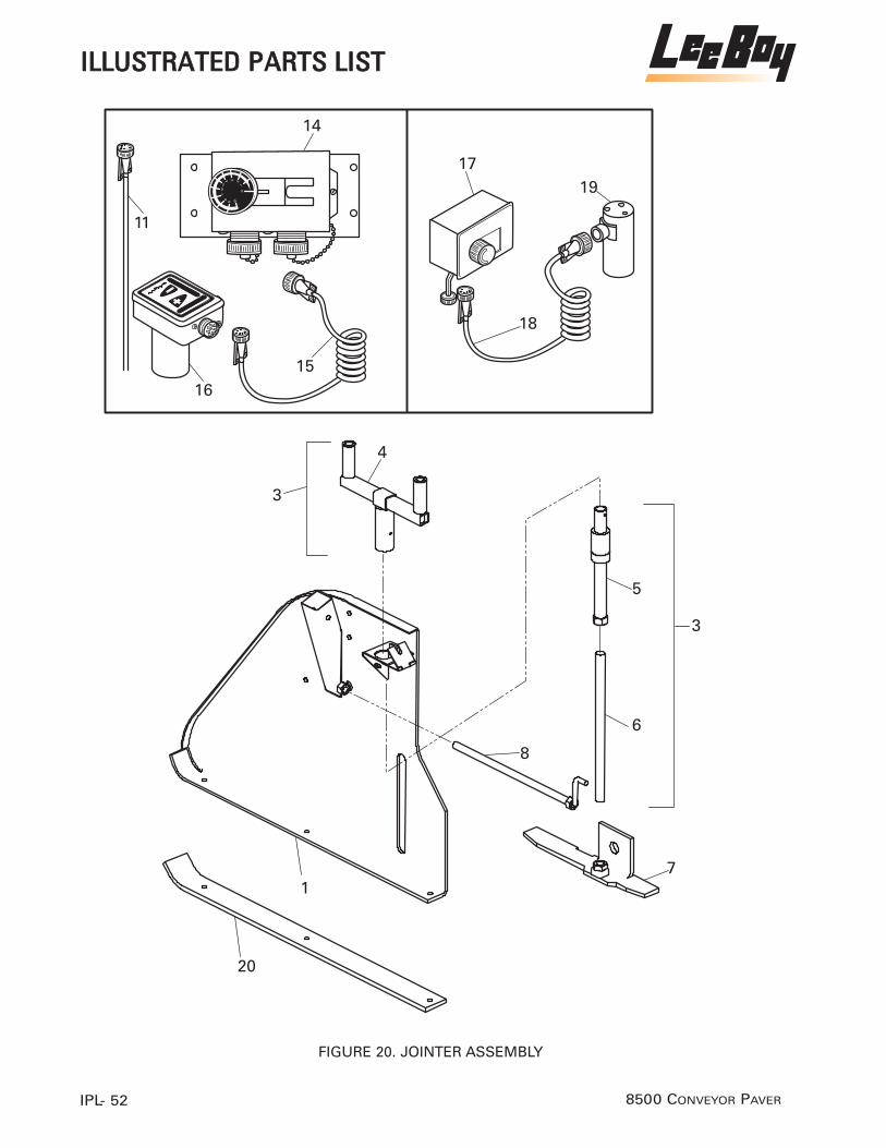
8500 CONVEYOR PAVERIPL- 52
�
�
�
�
�
�
��
��
����
��
��
�
�
����
�
� ��
��
FIGURE 20. JOINTER ASSEMBLY
IILLLLUUSSTTRRAATTEEDD PPAARRTTSS LLIISSTT
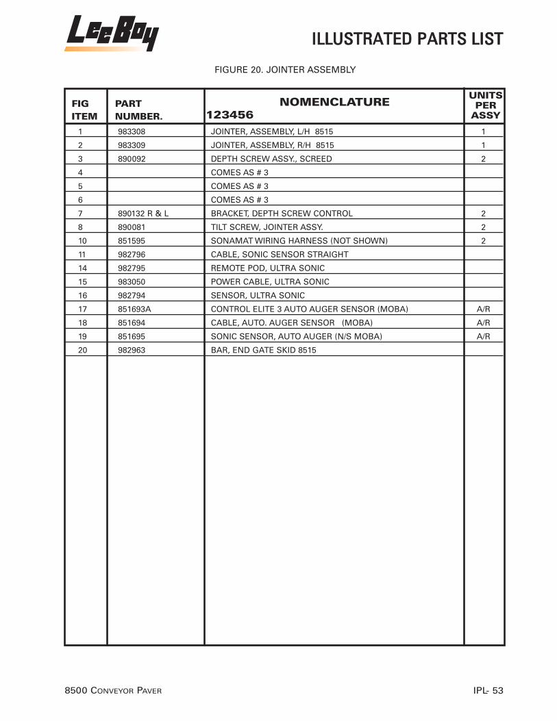
FIGITEM
UNITSPER
ASSYPART NUMBER.
NOMENCLATURE123456
1 983308 JOINTER, ASSEMBLY, L/H 8515 1
2 983309 JOINTER, ASSEMBLY, R/H 8515 1
3 890092 DEPTH SCREW ASSY., SCREED 2
4 COMES AS # 3
5 COMES AS # 3
6 COMES AS # 3
7 890132 R & L BRACKET, DEPTH SCREW CONTROL 2
8 890081 TILT SCREW, JOINTER ASSY. 2
10 851595 SONAMAT WIRING HARNESS (NOT SHOWN) 2
11 982796 CABLE, SONIC SENSOR STRAIGHT
14 982795 REMOTE POD, ULTRA SONIC
15 983050 POWER CABLE, ULTRA SONIC
16 982794 SENSOR, ULTRA SONIC
17 851693A CONTROL ELITE 3 AUTO AUGER SENSOR (MOBA) A/R
18 851694 CABLE, AUTO. AUGER SENSOR (MOBA) A/R
19 851695 SONIC SENSOR, AUTO AUGER (N/S MOBA) A/R
20 982963 BAR, END GATE SKID 8515
IILLLLUUSSTTRRAATTEEDD PPAARRTTSS LLIISSTT
IPL- 538500 CONVEYOR PAVER
FIGURE 20. JOINTER ASSEMBLY

8500 CONVEYOR PAVERIPL- 54
�
��
��
�
��
��
�
�����
�
�
���
��
��
�
��
�
��
����
��
�
��
��
FIGURE 21. SCREED ARM ASSEMBLY WITH CENTER TOE POINT
IILLLLUUSSTTRRAATTEEDD PPAARRTTSS LLIISSTT

FIGITEM
UNITSPER
ASSYPART NUMBER.
NOMENCLATURE123456
1 851206 EXTENSION, SCREED ARM 1
2 982743R REAR, SCREED ARM, (RIGHT) 1
(Serial #40383 and up)
3 982743L REAR, SCREED ARM (NOT SHOWN)
(Serial #40383 and up)
4 851209 MOUNT, PIVOT 1
5 851518 SCREW, ELECTRIC (6"INCH) 2
6 851210 EARS, PIVOT 2
7 851211 END, ROD END OF SCREW 1
8 851212 END, MOTOR END OF SCREED 1
9 851213 CLEVIS, 3/16" X 1/4" 1
10 851520 CABLE, HEIGHT LOCATOR 3/16x90 WITH 5”STROKE 1
11 851215 DECAL, HEIGHT 1
12 102-411-1A CAPSCREW, 1"x 2 1/2" 1
13 116-10 NUT, LOCK 1 " -8 HEX 1
14 102-611-1A CAPSCREW, 5/8" - 11 x 2 1/2” 3
15 116-7 NUT, LOCK 5/8 " 3
16 851134 CAPSCREW, 3/8" -16 x 3/4" 2
17 119-3 WASHER, FENDER 3/8" 2
18 102-9-1A CAPSCREW, 1/4"x 2" 1
19 116-1 NUT, LOCK 1/4" 1
20 102-408-1A CAPSCREW, 1/2" -13 x 1 3/4" 2
21 115-5-A NUT, LOCK 1/2" 2
22 851221 BRACKET, GRADE CONTROL 1
23 851001A MOUNTING PLATE 6” ELECTRIC SCREW
IILLLLUUSSTTRRAATTEEDD PPAARRTTSS LLIISSTT
IPL- 558500 CONVEYOR PAVER
FIGURE 21. SCREED ARM ASSEMBLY WITH CENTER TOE POINT

8500 CONVEYOR PAVERIPL- 56
��
�
�
�
��
��
��
�
����
��
��
��
��
��
�
�� �� ��
��
��
� �
��
���
�
FIGURE 22. PROPANE HEATER & AUTOMATIC IGNITORS
IILLLLUUSSTTRRAATTEEDD PPAARRTTSS LLIISSTT

FIGITEM
UNITSPER
ASSYPART NUMBER.
NOMENCLATURE123456
1 230010 L.P.G. TANK, 20 LBS. 1
2 230030 ADAPTER,P.O.L. 1
3 230110 GAUGE, L.P.G. PRESS. 1
4 230300 SOLENOID VALVE, 12 VOLT L.P.G. OPT.
5 982515 REGULATOR,0-60PSI. MRLP 1
6 230032 HOES, L.P.G. REGULATOR TO TEE 1
7 230034 HOSE, SCREED BURNER/IGNITOR TO 2
8 230080 TEE, 1/4" PIPE 2
9 230081 TEE, 1/4" STREET 2
10 230038 HOSE, L.P.G. TEE TO SCREED EXTENSION 2
11 230070 VALVE, 1/4” PETCOCK 2
12 230069 ADAPTER, PIPE TO HOSE (90)1/4 4
13 851225 HOSE, SCREED EXTENSION BURNER 2
14 982502 BURNER, WAND ASSY. ST5 IGNITER 2
15 851183 QUICK DISCONNECT, 1/4" MALE 2
16 982503 BURNER, EXTENSION ASSY. 2
17 982504 BURNER, WAND ASSY. ST5 IGNITER 2
18 230240 HOSE CLAMP 2
22 230024 IGNITOR
23 230950 PIPE NIPPLE, 1/4” X 2”
24 230140 PIPE NIPPLE, 1/4” X CLOSE
IILLLLUUSSTTRRAATTEEDD PPAARRTTSS LLIISSTT
IPL- 578500 CONVEYOR PAVER
FIGURE 22. PROPANE HEATER & AUTOMATIC IGNITORS

8500 CONVEYOR PAVERIPL- 58
����
�
�
����
�
�
FIGURE 23. AUGER EXTENSION 24”
IILLLLUUSSTTRRAATTEEDD PPAARRTTSS LLIISSTT

FIGITEM
UNITSPER
ASSYPART NUMBER.
NOMENCLATURE123456
1 851227 SHIELD, AUGER EXTENSION (RIGHT) 1
1A 851228 SHIELD, AUGER EXTENSION (LEFT) 1
2 851229 AUGER EXTENSION, (RIGHT) 1
2A 851230 AUGER EXTENSION, (LEFT) 1
3 851231 SUPPORT, AUGER ADJUSTABLE 1
4 116-10 NUT, HEX 1" 2
5 854003 COUPLING HALF 1
6 854004 COUPLING HALF, (WELDMENT) 1
7 900404 DOUBLE ROW CHAIN ASSY. (50-2) 1
IILLLLUUSSTTRRAATTEEDD PPAARRTTSS LLIISSTT
IPL- 598500 CONVEYOR PAVER
FIGURE 23. AUGER EXTENSION 24”

8500 CONVEYOR PAVERIPL- 60
���
�
��
�
�
�
�
�
���
�
�
��
��
�
��
��
������
�
��
�
���
��
��
��
��
FIGURE 24. PAVER LEVELING CONTROL (TOPCON)
IILLLLUUSSTTRRAATTEEDD PPAARRTTSS LLIISSTT

FIGITEM
UNITSPER
ASSYPART NUMBER.
NOMENCLATURE123456
1 851241 HOUSING, REAR SLIDE BAR 2
2 851242 BAR, ADJUSTABLE SLIDE 2
3 920070 WING BOLT, 3/8"-16 x 1" 2
4 851243 HOUSING, FRONT SLIDE BAR 2
5 143-5 LOCKNUT, 1/2"-13 HEX 2
6 851249 SKID 2
7 102-411-1A CAPSCREW, 1/2"X2 1/2" 2
8 851244 CLAMP, U' BOLT 2
9 851245 SPRING, TENSION 1
10 851246 CABLE 1 1/16 1
11 851247 ARM, SKID SUPPORT (REAR) 1
12 851248 ARM, SKID SUPPORT (FRONT) 1
13 102-611-1A CAPSCREW, 5/8"x 2 1/2" 1
14 116-7 NUT, 5/8" 1
15 851578 BRACKET, SONIC TRACKER 1
16 119-7 WASHER, FLAT 5/8" 1
17 102-617-1A CAPSCREW,5/8"x4" 1
18 851580 A/M MODULE & CABLE ASSEMBLY, w/BASE PLATE 1
19 851579 SONIC TRACKER 1
20 851581 WIRE BAIL, TEMPERATURE 1
21 851265 CASE FOR SONIC TRACKER 1
22 851575 PIVOT MOUNT, TOPCON / SPECTRA PHYSICS 2
23 9090-1125 BRACKET, Z ARM 1
24 300060 HANDLE, BOLT 1
25 102-606-1A CAPSCREW, 5/8"-11x1 1/4" 1
26 119-7 WASHER, FLAT 5/8" 1
27 851421 SLOPE METER A/R
28 851574 COILED CORD, TOPCON TRACKER / SLOPE A/R
IILLLLUUSSTTRRAATTEEDD PPAARRTTSS LLIISSTT
IPL- 618500 CONVEYOR PAVER
FIGURE 24. PAVER LEVELING CONTROL (TOPCON)

8500 CONVEYOR PAVERIPL- 62
�
�
�
�
��
�
�
�
��
����� �������!�
��
�
�
����
FIGURE 25. PAVER GRADE CONTROLS SPECTRA PHYSICS
IILLLLUUSSTTRRAATTEEDD PPAARRTTSS LLIISSTT

FIGITEM
UNITSPER
ASSYPART NUMBER.
NOMENCLATURE123456
1 851422 SONIC TRACER 1
2 851631 BRACKET, TRACER 1
3 851423 Z BRACKET ARM, 1 3/4" 1
4 920070 WINGBOLT, 3/8" 1
5 851575 MOUNT, PIVOT 1
6 300060 HANDLE, BOLT 1
7 119-7 WASHER, FLAT 5/8" 2
8 102-606-1A CAPSCREW, 5/8"-11 x 1" 2
9 851424 INTERFACE CONTROL BOX 1
10 851629 COILED CORD, TRACER / SLOPE (SPECTRA PHYSICS 1
11R 851633 SHORT COILED CORD, R.H. REMOTE (FITS LBI-25) 1
11L 851632 LONG COILED CORD, L.H. REMOTE (FITS LBI-25) 1
12 851265 CASE FOR SONIC TRACKER 1
13 851426 UNIVERSAL REMOTE 1
14 851630 COILED CORD, R-25 REMOTE 1
15 851687 BRACKET, REMOTE [SPECTRA] 1
16 851430 SLOPE MODULE, SCREED 1
17 851425 SHOCK MOUNT, SLOPE 1
IILLLLUUSSTTRRAATTEEDD PPAARRTTSS LLIISSTT
IPL- 638500 CONVEYOR PAVER
FIGURE 25. PAVER GRADE CONTROLS SPECTRA PHYSICS

8500 CONVEYOR PAVERIPL- 64
�
�
�
��
����
��
��
��
��
��
��
�
��
��
��
��
��
��
�
��
�
���
�
�
�
�
��
��
FIGURE 26. TRUCK HITCH ASSEMBLY
IILLLLUUSSTTRRAATTEEDD PPAARRTTSS LLIISSTT

FIGITEM
UNITSPER
ASSYPART NUMBER.
NOMENCLATURE123456
930010 TRUCK HITCH ASSEMBLY
1 930015 SUPPORT,PIVOTBAR 1
2 930020 ARM EXTENSION, R/H 1
3 930025 ARM EXTENSION, L/H 1
4 930030 GUIDE, WHEEL PIVOT ARM 2
5 620400 COLLAR, LOCK 4
6 810070 BUSHING, TRACK IDLER / TRUCK HITCH 4
7 930040 ROLLER 2
8 930045 AXLE, GUIDE WHEEL 2
9 930050 BEARING, TRUCK HITCH ROLLER 4
10 930055 GUIDE WHEEL, TRUCK HITCH 2
11 851111 CAPSCREW, 1/2" 13 x 2 FLAT HEAD SOCKET 2
12 810102 PUSH ROLLER, TRUCK WHEEL 2
13 810110 BEARING, PUSH ROLLER (1 1/4") 8
14 930060 ROLLER EXTENSION, BUMPER 2
15 930065 COVER, BACK PANEL 1
16 930070 CYLINDER, ARM EXTENSION 1
17 930075 SHAFT, BUMPER ROLLER 2
18 851112 WASHER, COUNTER SUNK 2
IILLLLUUSSTTRRAATTEEDD PPAARRTTSS LLIISSTT
IPL- 658500 CONVEYOR PAVER
FIGURE 26. TRUCK HITCH ASSEMBLY

8500 CONVEYOR PAVERIPL- 66
���
��
��
����
�
��
�
�
�
�� ��������#�!��������� � ��� ���� �
�
����������
FIGURE 27. UMBRELLA
IILLLLUUSSTTRRAATTEEDD PPAARRTTSS LLIISSTT
ASSEMBLY INSTRUCTIONS1. Install Umbrella Mounting bracket (See bracket mounting instructions furnishedwith each bracket).2. Insert ball stud on (#3) curved shaft into (#1) umbrella support shaft, align holes,and drive (#2) 3/16” X 1” spiral spring pins into position. Install (#5) locking han-dle.3. Place (#7) canvas cover over (#8) umbrella frame assembly and hook corners tobows – tie each bow securely with tie straps.4. Insert (#8) umbrella frame assembly with canvas in place into tube on (#3)curved shaft and insert (#6) bolt. Tighten snugly with nut (#4).5. Install complete umbrella into clamp on umbrella mounting bracket.Each bow may be raised individually until locked into open position. Each bow hastwo positions in which it can be locked open. This is to allow for arc stretch in canvas.•Part No. varies with color.

FIGITEM
UNITSPER
ASSYPART NUMBER.
NOMENCLATURE123456
1 920235 UMBRELLA A/R
IILLLLUUSSTTRRAATTEEDD PPAARRTTSS LLIISSTT
IPL- 678500 CONVEYOR PAVER
FIGURE 27. UMBRELLA

8500 CONVEYOR PAVERIPL- 68
��� ����� ��
��������������!�����!!
���
����
FIGURE 28. STRIKE OFFS & EXTENSIONS
IILLLLUUSSTTRRAATTEEDD PPAARRTTSS LLIISSTT

FIGITEM
UNITSPER
ASSYPART NUMBER.
NOMENCLATURE123456
1 860091L STRIKE OFF, 12" LEFT SIDE A/R
2 860091R STRIKE OFF, 12" RIGHT SIDE A/R
1 860093L STRIKE OFF, 18" LEFT SIDE A/R
2 860093R STRIKE OFF, 18" RIGHT SIDE A/R
1 860095L STRIKE OFF, 24" LEFT SIDE A/R
2 860095R STRIKE OFF, 24" RIGHT SIDE A/R
3 851634L EXTENSION, 6' LEFT SIDE A/R
4 851634R EXTENSION, 6' RIGHT SIDE A/R
5 851635L ROLL UP CURB ATTACHMENT, 12"LEFT SIDE A/R
6 851635R ROLL UP CURB ATTACHMENT, 12"RIGHT SIDE A/R
5 851636L ROLL UP CURB ATTACHMENT, 24" LEFT SIDE (STANDARD A/R
6 851636R ROLL UP CURB ATTACHMENT, 24" RIGHT SIDE (STANDARD) A/R
IILLLLUUSSTTRRAATTEEDD PPAARRTTSS LLIISSTT
IPL- 698500 CONVEYOR PAVER
FIGURE 28. STRIKE OFFS & EXTENSIONS

1 320001 4 CYL. DIESEL ENG., HATZ 4L41C (SILENT-PAK) IPL-33
18 851580 A/M MODULE & CABLE ASSEMBLY, w/BASE PLATE IPL-61
35 920233 ADAPTER, 1/2"M.P.T.x #8 MALE SAE. IPL-23
4 910129 ADAPTER, 1/4" MPT x 1/4" MJIC (90 DEGREE) IPL-21
12 230069 ADAPTER, PIPE TO HOSE (90)1/4 IPL-57
33 2404-10-8. ADAPTER,HYD. HOSE IPL-3
41 6801-10-8. ADAPTER,HYD. HOSE IPL-3
42 6400-10-8. ADAPTER,HYD. HOSE IPL-3
43 6401-8-8. ADAPTER,HYD. HOSE IPL-3
33 2404-10-8. ADAPTER,HYD. HOSE IPL-5
41 6801-10-8. ADAPTER,HYD. HOSE IPL-5
42 6400-10-8. ADAPTER,HYD. HOSE IPL-5
43 6401-8-8. ADAPTER,HYD. HOSE IPL-5
2 230030 ADAPTER,P.O.L. IPL-57
7 851184 ADJUSTING SCREW, SCREED EXTENSION IPL-45
34 985010 ALTERNATOR, 12 VOLT IPL-33
3 930025 ARM EXTENSION, L/H IPL-65
2 930020 ARM EXTENSION, R/H IPL-65
17 900060 ARM, AUTO. CONVEYOR SWITCH IPL-39
16 320245 ARM, LEFT DRIVE IPL-29
17 900025 ARM, RIGHT DRIVE IPL-29
12 851248 ARM, SKID SUPPORT (FRONT) IPL-61
11 851247 ARM, SKID SUPPORT (REAR) IPL-61
1 980607L ASSEMBLY IN FRONT OF UNDER CARRIAGE, LH IPL-7
2 980607R ASSEMBLY IN FRONT OF UNDER CARRIAGE,,RH IPL-7
26D 851122R ASSEMBLY, J GUARD RIGHT SIDE (Low Deck) IPL-9
26C 851122L ASSEMBLY, J GUARD LEFT SIDE (Low Deck) IPL-9
19 860073 AUGER ASSEMBLY, L.H. IPL-17
17 860083 AUGER ASSEMBLY,R.H. IPL-17
24 853410 AUGER COVER, BOTTOM IPL-17
2A 851230 AUGER EXTENSION, (LEFT) IPL-59
2 851229 AUGER EXTENSION, (RIGHT) IPL-59
13A 860135 AUGER EXTENSION, L.H. IPL-17
13 860136 AUGER EXTENSION, R.H. IPL-17
18 861150C AUGER SECTION, L.H. IPL-17
16 861140C AUGER SECTION, R.H. IPL-17
8 930045 AXLE, GUIDE WHEEL IPL-65
FIGITEM
PAGEPART NUMBER.
NOMENCLATURE123456
8500 CONVEYOR PAVERIPL- 70
IINNDDEEXX PPAARRTTSS LLIISSTT

7 851103 AXLE; MAIN IPL-3
26 851504 BACKUP ALARM, PRESSURE SWITCH IPL-29
29 853598 BAR, .375 X 6.25 X 7.00 IPL-13
30 853595 BAR, 125 X 1.50 X 9.50 IPL-13
2 851242 BAR, ADJUSTABLE SLIDE IPL-61
18 851118A BAR, CONVEYOR FLIGHT BAR (QUICK CHANGE) IPL-9
20 982963 BAR, END GATE SKID 8515 IPL-53
23 920041 BAR, GUIDE (OUTER) IPL-13
3 851166 BAR, INSTRUMENT SLIDE (HIGH DECK) IPL-41
3A 851167 BAR, INSTRUMENT SLIDE (LOW DECK) IPL-41
1 851173 BAR, SEAT SLIDE IPL-43
15 850130 BEARING IPL-17
10 810140 BEARING, 2 1/4" PILLOW BLOCK IPL-3
7 851130 BEARING, AUGER, AXLE, IDLER IPL-9
5 250150 BEARING, CONVEYOR PULLEY/ VIBRATOR SHAFT IPL-51
36 810110 BEARING, PUSH ROLLER (1 1/4") IPL-3
36 810110 BEARING, PUSH ROLLER (1 1/4") IPL-5
13 810110 BEARING, PUSH ROLLER (1 1/4") IPL-65
9 870030 BEARING, SCREED FLIGHT SCREW IPL-45
16 870030 BEARING, SCREED FLIGHT SCREW IPL-49
9 930050 BEARING, TRUCK HITCH ROLLER IPL-65
851627 BED ASSY. 8500 CONVEYOR IPL-9
30 320090 BELT, ALTERNATOR / BLOWER IPL-33
14 850080 BLOCK LINK IPL-9
10 320340 BLOCK, TERMINAL IPL-33
33 320290 BLOWER FAN IPL-33
20 861141 BOLT AND NUT, CASTED AUGER IPL-17
2 851148 BOLT, CONVEYOR DRIVE CHAIN ADJUSTER IPL-19
15 811308 BOLT, FOR PAD IPL-3
3 851538 BOOT, JOYSTICK IPL-31
3 320224 BRACE, PUMP SUNDSTRAND IPL-29
7 890132 R & L BRACKET, DEPTH SCREW CONTROL IPL-53
22 851221 BRACKET, GRADE CONTROL IPL-55
22 920125 BRACKET, PUMP CABLES IPL-29
15 851687 BRACKET, REMOTE [SPECTRA] IPL-63
41 900029 BRACKET, SAFETY SWITCH IPL-23
15 851578 BRACKET, SONIC TRACKER IPL-61
FIGITEM
PAGEPART NUMBER.
NOMENCLATURE123456
IINNDDEEXX PPAARRTTSS LLIISSTT
IPL- 718500 CONVEYOR PAVER

2 851631 BRACKET, TRACER IPL-63
12 910058 BRACKET, VALVE LEVER IPL-37
23 230062 BRACKET, W/CLAMP, LPG TANK MOUNT IPL-41
16 480260 BRACKET, WATER / FUEL PUMP MOUNT IPL-37
23 9090-1125 BRACKET, Z ARM IPL-61
31 851644 BREATHER; CYLINDER IPL-3
3 851199 BULKHEAD, HYDRAULIC IPL-49
47 851600-1 BURNER PIPE EXTENSION IPL-47
48 851197-1 BURNER PIPE, MAIN IPL-47
16 982503 BURNER, EXTENSION ASSY. IPL-57
14 982502 BURNER, WAND ASSY. ST5 IGNITER IPL-57
17 982504 BURNER, WAND ASSY. ST5 IGNITER IPL-57
20 851460 BUSHING 004017 IPL-3
18 851179 BUSHING, SCREED EXTENSION (3" LONG) IPL-45
2 851179 BUSHING, SCREED EXTENSION (3" LONG) IPL-45
39 810070 BUSHING, TRACK IDLER / TRUCK HITCH IPL-3
39 810070 BUSHING, TRACK IDLER / TRUCK HITCH IPL-5
8 810070 BUSHING, TRACK IDLER / TRUCK HITCH IPL-17
6 810070 BUSHING, TRACK IDLER / TRUCK HITCH IPL-65
44 5406-12-8. BUSHING,3/4" M.P.T.x1/2" F.P.T. IPL-3
44 5406-12-8. BUSHING,3/4" M.P.T.x1/2" F.P.T. IPL-5
21 811314 BUSHING; BO TRACK IPL-3
32 102-209-1A C5HH, .375-16 X 2.00GR5 IPL-13
10 851246 CABLE 1 1/16 IPL-61
18 851694 CABLE, AUTO. AUGER SENSOR (MOBA) IPL-53
44 920136 CABLE, DRIVE/ EXTENSION IPL-25
10 851520 CABLE, HEIGHT LOCATOR 3/16x90 WITH 5”STROKE IPL-55
17 920130 CABLE, R.H. CONTROL (123" X 3" STROKE) IPL-23
18 920130 CABLE, R.H. CONTROL (123" X 3" STROKE) IPL-23
3 920140 CABLE, R.H. DRIVE / CONTROL (116" X 3" STROKE IPL-27
5 920140 CABLE, R.H. DRIVE / CONTROL (116" X 3" STROKE IPL-27
6 920140 CABLE, R.H. DRIVE / CONTROL (116" X 3" STROKE IPL-27
19 920120 CABLE, R.H. DRIVE, AUGER & PUMP (104" X 3") IPL-23
20 920120 CABLE, R.H. DRIVE, AUGER & PUMP (104" X 3") IPL-29
17 920120 CABLE, SCREED EXTENSION IPL-41
21 920120 CABLE, SCREED EXTENSION IPL-41
11 982796 CABLE, SONIC SENSOR STRAIGHT IPL-53
8500 CONVEYOR PAVERIPL- 72
IINNDDEEXX PPAARRTTSS LLIISSTT
FIGITEM
PAGEPART NUMBER.
NOMENCLATURE123456

IINNDDEEXX PPAARRTTSS LLIISSTT
IPL- 738500 CONVEYOR PAVER
FIGITEM
PAGEPART NUMBER.
NOMENCLATURE123456
11 920161 CABLE, THROTTLE IPL-23
2 920161 CABLE, THROTTLE IPL-39
6 811364 CAP SCREW IPL-3
12 811352 CAP SCREW IPL-3
25 811330A CAP SCREW IPL-3
27 811330 CAP SCREW IPL-3
14 100-913-1A CAP SCREW, 1"-14x3 GR. 8 HEX HEAD IPL-19
6 851111 CAP SCREW, 1/2"-13 x2"HEX HEAD IPL-19
24 102-5-1A CAP SCREW, 1/4"-20x 1" HEX HEAD IPL-19
16 100-915-1A CAP SCREW, 1'-14x3 1/2", GR.8 HEX HEAD IPL-19
11 102-203-1A CAP SCREW, 3/8"-16 x 3/4"HEX HEAD IPL-19
27 102-114-1A CAP SCREW, 5/16"-18 x 3 1/2" IPL-19
9 811352 CAP SCREW, 5/8”-18 x 2 1/4” (torque 180 ft.lbs.) IPL-3
18 102-607-1A CAP SCREW, 5/8"-11x1 1/2" HEX HEAD IPL-19
3 140030HL CAP, HYD. TANK (LOCKABLE) IPL-21
5 320227 CAPSCREW IPL-29
6 320228 CAPSCREW IPL-29
15 320243 CAPSCREW IPL-29
24 320227 CAPSCREW IPL-29
2 102-415-1A CAPSCREW 1/2 - 13 x 31/2” IPL-43
6 102-206-1A CAPSCREW 3/8 - 16 - 1 1/4” IPL-43
11 102-205-1A CAPSCREW 3/8” - 16 x 1” HEX IPL-41
12 102-411-1A CAPSCREW, 1"x 2 1/2" IPL-55
20 102-408-1A CAPSCREW, 1/2" -13 x 1 3/4" IPL-55
11 851111 CAPSCREW, 1/2" 13 x 2 FLAT HEAD SOCKET IPL-65
41 102-406-1A CAPSCREW, 1/2"x 1 1/4" IPL-47
10 102-405-1A CAPSCREW, 1/2"x1" IPL-9
7 102-411-1A CAPSCREW, 1/2"X2 1/2" IPL-61
1 851111 CAPSCREW, 1/2"x2" IPL-9
20 100-408-1 CAPSCREW, 1/2"x20x1 1/2" HEX HEAD IPL-45
52 102-3-1A CAPSCREW, 1/4"-20 x 3/4" IPL-25
18 102-9-1A CAPSCREW, 1/4"x 2" IPL-55
14 102-615-1A CAPSCREW, 11 x 3 1/2" IPL-41
16 851134 CAPSCREW, 3/8" -16 x 3/4" IPL-55
9 102-205-1A CAPSCREW, 3/8"x 1" IPL-41
9 102-205-1A CAPSCREW, 3/8X1" IPL-39
38 102-1091A CAPSCREW, 5/16"-18x201/4" IPL-23

8500 CONVEYOR PAVERIPL- 74
IINNDDEEXX PPAARRTTSS LLIISSTT
FIGITEM
PAGEPART NUMBER.
NOMENCLATURE123456
14 102-611-1A CAPSCREW, 5/8" - 11 x 2 1/2” IPL-55
8 102-606-1A CAPSCREW, 5/8"-11 x 1" IPL-63
25 102-606-1A CAPSCREW, 5/8"-11x1 1/4" IPL-61
28 102-606-1A CAPSCREW, 5/8"-11x1 1/4" HEX HEAD IPL-45
36 102-607-1A CAPSCREW, 5/8"x 1 1/2" IPL-47
13 102-611-1A CAPSCREW, 5/8"x 2 1/2" IPL-61
24 800282 CAPSCREW, 5/8"x1 1/4" IPL-9
32A 851652 CAPSCREW, 5/8”x1” FLAT SOCKET HEAD IPL-9
32A 851652 CAPSCREW, 5/8”x1” FLAT SOCKET HEAD IPL-11
29A 851653 CAPSCREW, 5/8”x2” FLAT SOCKET HEAD IPL-9
14 102-309-1A CAPSCREW, 7/16"x2" HEX HEAD IPL-45
24 860048 CAPSCREW, 7/16"x2" HEX HEAD IPL-45
4 851134 CAPSCREW, HEX, 3/8"x3/4" IPL-49
12 870279 CAPSCREW, SOCKET HEAD SHOULDER IPL-45
29 920229 CAPSCREW,5/8"-11x7 1/2" IPL-23
17 102-617-1A CAPSCREW,5/8"x4" IPL-61
27A 850003 CARTRIDGE VALVE, 2-SPEED IPL-21
27 851236 CARTRIDGE VALVE, 2-SPEED (H.P.S.) IPL-21
26 851235 CARTRIDGE VALVE, AUTO AUGER (H.P.S.) IPL-21
26A 850004 CARTRIDGE VALVE, AUTO AUGER (WATERMAN) IPL-21
22 851628A-1 CARTRIDGE VALVE, AUTO CONVEYOR (H.P.S.) IPL-21
21 851265 CASE FOR SONIC TRACKER IPL-61
12 851265 CASE FOR SONIC TRACKER IPL-63
17 920210 CASTED HANDLE, R.H. CONTROL IPL-27
23 853403 CENTER AUGER SUPPORT IPL-17
9 840162 CENTER SHIELD, CONVEYOR REAR IPL-13
33 102-407-1A CH5HH, .500- 13 X 1.50, GR5 IPL-13
23 851121 CHAIN, CONVEYOR DRIVE IPL-9
4 851121 CHAIN, CONVEYOR DRIVE (#80) IPL-19
33 870190 CHAIN, CROWN & VALLEY #40 IPL-45
4 860090 CHAIN, PAVER AUGER DRIVE IPL-17
8 851151L CHAINGUARD, CONVEYOR L.H. DRIVE IPL-19
8A 851151R CHAINGUARD, CONVEYOR R.H. DRIVE IPL-19
24 982024 CITRUS TANK (Not Shown) IPL-41
25 320030 CLAMP, 2" EXH. PIPE IPL-33
8 851244 CLAMP, U' BOLT IPL-61
19 350050 CLEVIS, 1/4" IPL-27
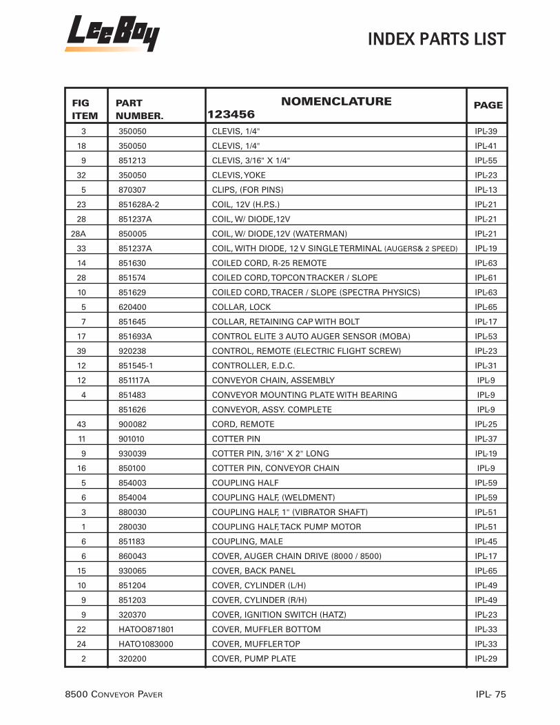
IINNDDEEXX PPAARRTTSS LLIISSTT
IPL- 758500 CONVEYOR PAVER
FIGITEM
PAGEPART NUMBER.
NOMENCLATURE123456
3 350050 CLEVIS, 1/4" IPL-39
18 350050 CLEVIS, 1/4" IPL-41
9 851213 CLEVIS, 3/16" X 1/4" IPL-55
32 350050 CLEVIS, YOKE IPL-23
5 870307 CLIPS, (FOR PINS) IPL-13
23 851628A-2 COIL, 12V (H.P.S.) IPL-21
28 851237A COIL, W/ DIODE,12V IPL-21
28A 850005 COIL, W/ DIODE,12V (WATERMAN) IPL-21
33 851237A COIL, WITH DIODE, 12 V SINGLE TERMINAL (AUGERS& 2 SPEED) IPL-19
14 851630 COILED CORD, R-25 REMOTE IPL-63
28 851574 COILED CORD, TOPCON TRACKER / SLOPE IPL-61
10 851629 COILED CORD, TRACER / SLOPE (SPECTRA PHYSICS) IPL-63
5 620400 COLLAR, LOCK IPL-65
7 851645 COLLAR, RETAINING CAP WITH BOLT IPL-17
17 851693A CONTROL ELITE 3 AUTO AUGER SENSOR (MOBA) IPL-53
39 920238 CONTROL, REMOTE (ELECTRIC FLIGHT SCREW) IPL-23
12 851545-1 CONTROLLER, E.D.C. IPL-31
12 851117A CONVEYOR CHAIN, ASSEMBLY IPL-9
4 851483 CONVEYOR MOUNTING PLATE WITH BEARING IPL-9
851626 CONVEYOR, ASSY. COMPLETE IPL-9
43 900082 CORD, REMOTE IPL-25
11 901010 COTTER PIN IPL-37
9 930039 COTTER PIN, 3/16" X 2" LONG IPL-19
16 850100 COTTER PIN, CONVEYOR CHAIN IPL-9
5 854003 COUPLING HALF IPL-59
6 854004 COUPLING HALF, (WELDMENT) IPL-59
3 880030 COUPLING HALF, 1" (VIBRATOR SHAFT) IPL-51
1 280030 COUPLING HALF, TACK PUMP MOTOR IPL-51
6 851183 COUPLING, MALE IPL-45
6 860043 COVER, AUGER CHAIN DRIVE (8000 / 8500) IPL-17
15 930065 COVER, BACK PANEL IPL-65
10 851204 COVER, CYLINDER (L/H) IPL-49
9 851203 COVER, CYLINDER (R/H) IPL-49
9 320370 COVER, IGNITION SWITCH (HATZ) IPL-23
22 HATOO871801 COVER, MUFFLER BOTTOM IPL-33
24 HATO1083000 COVER, MUFFLER TOP IPL-33
2 320200 COVER, PUMP PLATE IPL-29

8500 CONVEYOR PAVERIPL- 76
IINNDDEEXX PPAARRTTSS LLIISSTT
FIGITEM
PAGEPART NUMBER.
NOMENCLATURE123456
3 320200 COVER, PUMP PLATE IPL-33
24 320500 COVER,ENGINE ACCESS(HATZ 4L41C IPL-39
35 102-607-1A CSHH, .625- 11 X 1.50, GR5 IPL-13
34 851111 CSSH, .500- 13 X 2.00, GR5 IPL-13
10 851548 CURLY CORD, STEERING BOX TO JUNCTION BOX IPL-31
22 851153 CUT-OFF LEFT SIDE IPL-19
23 851154 CUT-OFF RIGHT SIDE IPL-19
16 930070 CYLINDER, ARM EXTENSION IPL-65
12 920165 DASH, COMPLETE 8500/8000D IPL-23
11 851215 DECAL, HEIGHT IPL-55
2 851667 DECAL, STEERING DASH IPL-31
7 851667 DECAL, STEERING KNOB IPL-31
26A 850038 L DEFLECTOR, LEFT SIDE (High Deck) IPL-9
26B 850038 R DEFLECTOR, RIGHT SIDE (High Deck) IPL-9
3 890092 DEPTH SCREW ASSY., SCREED IPL-53
37 320110 DIPSTICK, ENGINE OIL LEVEL IPL-33
7 900404 DOUBLE ROW CHAIN ASSY. (50-2) IPL-59
25 851160-2 DRIVE CPLG, TANDEM PUMP IPL-29
8 851160-1 DRIVE CPLG. CHARGE PUMP IPL-29
8 851116 DRIVE SHAFT, CONVEYOR IPL-9
6 851210 EARS, PIVOT IPL-55
35 310060 ELEMENT, AIR FILTER IPL-33
23 310060 ELEMENT, AIR FILTER (HATZ DIESEL) IPL-39
8 290030 ELEMENT, CHARGE / RETURN FILTER IPL-39
38 310080 ELEMENT, FUEL FILTER IPL-33
1 310080 ELEMENT, FUEL FILTER (HATZ DIESEL) IPL-39
39 310070 ELEMENT, OIL FILTER IPL-33
10 851647 END CAP, FOR AUGER IPL-17
8 851212 END, MOTOR END OF SCREED IPL-55
7 851211 END, ROD END OF SCREW IPL-55
9A 860051HDL ENDMOUNT, L.H. AUGER IPL-17
9 860051HDR ENDMOUNT, R.H. AUGER IPL-17
29 320250-4 EXH. MANIFOLD, HATZ 4 CYL. IPL-33
3 851634L EXTENSION, 6' LEFT SIDE IPL-69
4 851634R EXTENSION, 6' RIGHT SIDE IPL-69
1 851206 EXTENSION, SCREED ARM IPL-55
4 851181L EXTENSION, UPPER, LEFT SIDE IPL-45

IINNDDEEXX PPAARRTTSS LLIISSTT
IPL- 778500 CONVEYOR PAVER
FIGITEM
PAGEPART NUMBER.
NOMENCLATURE123456
18 320381 FLAP, IGNITION SWITCH IPL-33
28 985063 FLASHING, CENTER FRONT LIP IPL-13
13 985062 FLASHING, SIDE STRIP FRONT LIP IPL-13
13 851370 FLIGHT SCREW ASSEMBLY IPL-49
13 910054FLS FLOAT, ASSEMBLY SCREED IPL-37
28 811406 FRONT IDLER, TRACK (N/S CASTED) IPL-3
31 985581 FRONT LIP CLAMP IPL-13
11 985669 FRONT LIP GUARD IPL-13
2 140030FL FUEL TANK CAP, LOCKABLE IPL-27
28 320260 GASKET, EXH. MANIFOLD TO CYL. HEAD IPL-33
42 HATO01603700 GASKET, MUFFLER TO MANIFOLD IPL-35
2 943306 GAUGE, FUEL LEVEL IPL-23
3 230110 GAUGE, L.P.G. PRESS. IPL-57
3 943270 GAUGE, OIL PRESSURE IPL-23
7 330040 GAUGE, TACK TEMP/ HYD. OIL TEMP. IPL-21
1 943309 GAUGE, VOLT METER IPL-23
14 140610 GREASE FITTING IPL-17
14 870276 GRIP, HANDLE IPL-49
8 851202 GROMMET IPL-49
3 851180 GUARD, HOUSING SPECIFY (L/H OR R/H) IPL-45
22 920032 GUIDE BAR ASSEMBLY IPL-13
10 930055 GUIDE WHEEL, TRUCK HITCH IPL-65
39 851299 GUIDE, EXTENSION LOWER, (WELDMENT) IPL-47
40 851298 GUIDE, EXTENSION TOP IPL-47
4 930030 GUIDE, WHEEL PIVOT ARM IPL-65
17 850215A HALF LINK, CONVEYOR CHAIN IPL-9
20 920220A HANDLE & NOZZLE, FUEL WASH-DOWN IPL-37
21 920220 HANDLE & NOZZLE, FUEL WASH-DOWN IPL-37
12 920230 HANDLE, (R/H) (LEE-BOY) IPL-27
24 300060 HANDLE, BOLT IPL-61
6 300060 HANDLE, BOLT IPL-63
35 851195 HANDLE, CRANK IPL-45
24 920097 HANDLE, DRIVE IPL-23
11 920228 HANDLE, DRIVE L/H (LEE-BOY) IPL-27
3 910060 HANDLE, HORIZONTAL IPL-37
9 910130 HANDLE, MONOBLOCK VALVE (CONVEYOR WINGS) IPL-21
2 910060A HANDLE, VERTICAL IPL-37

FIGITEM
PAGEPART NUMBER.
NOMENCLATURE123456
7 290010 HEAD, CHARGE / RETURN FILTER IPL-39
27 320510 HEAT SHIELD, MUFFLER IPL-33
10 851160A HIGH VOLUMN PUMP, AUGERS AND CONVEYORS IPL-29
20 840157 HINGED PANEL, L/H IPL-13
21 840156 HINGED PANEL, R/H IPL-13
6 230032 HOES, L.P.G. REGULATOR TO TEE IPL-57
8 840166 HOLD DOWN IPL-13
11 851174 HOLDER, SEAT IPL-43
22 160320 HORN, BACKUP ALARM IPL-41
7 851497 HOSE & DRAIN FITTING, ENGINE OIL DRAIN IPL-33
46 8550 HOSE ASSY. L.H. TRACK TENSIONER IPL-3
46 8550 HOSE ASSY. L.H. TRACK TENSIONER IPL-5
34 8550B HOSE ASSY. TRACK R.H. TENSIONER IPL-3
34 8550B HOSE ASSY. TRACK R.H. TENSIONER IPL-5
47 8551 HOSE ASSY.R.H. TRACK TENSIONER IPL-3
47 8551 HOSE ASSY.R.H. TRACK TENSIONER IPL-5
18 230240 HOSE CLAMP IPL-57
14 920200 HOSE REEL, MACHINE WASHDOWN IPL-37
10 230038 HOSE, L.P.G. TEE TO SCREED EXTENSION IPL-57
19 920221 HOSE, PUMP TO HOSE REEL IPL-37
7 230034 HOSE, SCREED BURNER/IGNITOR TO IPL-57
13 851225 HOSE, SCREED EXTENSION BURNER IPL-57
23 920224 HOSE, TO SPRAYDOWN HANDLE IPL-37
5 851234 HOSE, VENT IPL-21
4 5120-1200 HOUR-METER IPL-23
4 851243 HOUSING, FRONT SLIDE BAR IPL-61
24 920051 HOUSING, GUIDE BAR (INNER) IPL-13
1 851241 HOUSING, REAR SLIDE BAR IPL-61
4 880042 HOUSING, VIBRATOR ECCENTRIC IPL-51
9 811331 HYD CYL, 8000C/8500 TRACK IPL-7
3 811362 HYD MOTOR, PAVER/635B 2-SPEED IPL-7
21 910170 HYD. CYL., CUTOFF IPL-19
18 840020 HYD. CYL., HOPPER LIFT (8000 / 8500) (3X12) IPL-13
3 840030 HYD. CYL., HOPPER WING (8000 / 8500) IPL-13
23 851191 HYD. CYL., SCREED EXT. (L.H.) IPL-45
23 851192 HYD. CYL., SCREED EXTENSION (R.H.) IPL-45
12 851436 HYD. CYL., SCREED LIFT (1000C / 8000C / 8500) IPL-19
8500 CONVEYOR PAVERIPL- 78
IILLLLUUSSTTRRAATTEEDD PPAARRTTSS LLIISSTT

FIGITEM
PAGEPART NUMBER.
NOMENCLATURE123456
IILLLLUUSSTTRRAATTEEDD PPAARRTTSS LLIISSTT
IPL- 798500 CONVEYOR PAVER
32 811331 HYD. CYL., TRACK TENSIONER IPL-3
4 811362 HYD. MOTOR, 2-SPEED IPL-3
1 860010 HYD. MOTOR, AUGER (ALL) / CONVEYOR (8000B) IPL-17
21 260130 HYD. MOTOR, CONVEYOR MAIN IPL-9
15 851400 HYD. OIL COOLER, W / FAN, MOTOR & SENSOR IPL-39
16 853370 HYD. TANK, BOTTOM IPL-13
16 851545 HYD.PUMP, TANDEM PROPULSION (W/E.D.C.) (SUNSTRAND) IPL-31
1 260130 HYDRAULIC MOTOR IPL-19
16B 985663 HYDROLIC PUMP TANDOM (REX ROTH) IPL-31
16A 851525 HYDROLIC PUMP TANDOM (REX ROTH) DEN CONNECTOR IPL-31
28 850120 IDLER, CONVEYOR CHAIN FRONT IPL-9
11 983530 IDLER, FRONT B1 8515 IPL-7
17 320380 IGNITION KEY, HATZ DIESEL IPL-33
19 320390 IGNITION SWITCH, HATZ DIESEL IPL-33
22 230024 IGNITOR IPL-57
12 320385 INDICATOR LAMP, AIR FILTER IPL-33
11 320383 INDICATOR LAMP, ENGINE TEMP IPL-33
14 320386 INDICATOR LIGHT, BATTERY CHARGE IPL-33
8 320386 INDICATOR LIGHT, BATTERY, (WITHOUT BULB) IPL-23
13 320384 INDICATOR LIGHT, ENG.OIL PRESS. IPL-33
7 910055 INLET COVER, V-20 (W/RELIEF) IPL-37
43 310090 IN-LINE FUEL FILTER IPL-35
2 280040 INSERT, 3-JAW COUPLING IPL-51
9 851424 INTERFACE CONTROL BOX IPL-63
1 983308 JOINTER, ASSEMBLY, L/H 8515 IPL-53
2 983309 JOINTER, ASSEMBLY, R/H 8515 IPL-53
5 851537 JOYSTICK ASSEMBLY IPL-31
13 851549 JUNCTION BOX, SUNDSTRAND IPL-31
7 320380 KEY, HATZ ENGINE IPL-23
12 860043-1 KIT, AUGER COVER CLOSING IPL-17
1 851666 KNOB, JOYSTICK IPL-31
26 920225 KNOB, ROUND BALL (1 7/8" X 1/2"-13 THREADS) IPL-23
20 920225 KNOB, ROUND BALL (1 7/8" X 1/2"-13 THREADS) IPL-27
8 850670 KNOB, STEERING IPL-31
46 851156 KNOB. IPL-25
23 920096 L.H. PIVOT, FOR.& REV.LEVER (LEFT SIDE) IPL-23
1 230010 L.P.G. TANK, 20 LBS. IPL-57

FIGITEM
PAGEPART NUMBER.
NOMENCLATURE123456
36 320120 LEVER, ENGINE THROTTLE IPL-33
16 920210A LEVER, SCREED EXT. REMOTE IPL-41
6 320120 LEVER, THROTTLE IPL-39
7 851201 LID, SCREED IPL-49
15 320360 LIGHT BULB, INDICATOR LAMP IPL-33
10 901010 LINK ASSY., VALVE LEVER IPL-37
15 850090 LINK PIN, CONVEYOR CHAIN IPL-9
13 850070A LINK, MASTER IPL-9
17 811312 LINK, TRACK LINK REPAIR SEG. IPL-3
18 900075 LINKAGE IPL-39
15 142-10 LOCK NUT, 1"-14 HEX IPL-19
5 118-5 LOCK WASHER IPL-3
11 118-7 LOCK WASHER IPL-3
20 900077 LOCK WASHER IPL-39
7 920072 LOCK WASHER, 3/8" IPL-27
17 851373 LOCK, ARM IPL-49
5 143-5 LOCKNUT, 1/2"-13 HEX IPL-61
13 143-3 LOCKNUT, 3/8"-16 IPL-45
25 118-7 LOCKWASHER, 5/8" IPL-9
14 119-7 LOCKWASHER, 5/8" IPL-27
26 811328 LOCKWASHER; ROLLER 12MM IPL-3
11L 851632 LONG COILED CORD, L.H. REMOTE (FITS LBI-25) IPL-63
31 850001 MANIFOLD ASSEMBLY, AUGERS AND 2- SPEED IPL-19
25 850001 MANIFOLD, AUTO AUGER/ 2-SPEED (H.P.S.) IPL-21
21 851628A MANIFOLD, AUTO CONVEYOR (H.P.S.) IPL-21
16 851628 MANIFOLD, AUTO CONVEYOR (WATERMAN) IPL-21
45 851544 MANIFOLD, N/S TRACK TENSIONER IPL-3
45 851544 MANIFOLD, N/S TRACK TENSIONER IPL-5
10 910122 MANIFOLD, SIDE WING IPL-21
4A 860049 MASTER LINK (60H) IPL-17
14 851547 MC. MICRO CONTROLLER IPL-31
14A 852410 MC. MICRO CONTROLLER (USE WITH REX ROTH PUMPS) IPL-31
16 900050 MIRCO SWITCH, AUTO. CONVEYORS IPL-39
27 983405 MOTOR, HYDRAULIC SCREED VIBRATOR (8515) IPL-45
3 851149 MOUNT, CONVEYOR DRIVE MOTOR IPL-19
4 851209 MOUNT, PIVOT IPL-55
5 851575 MOUNT, PIVOT IPL-63
8500 CONVEYOR PAVERIPL- 80
IILLLLUUSSTTRRAATTEEDD PPAARRTTSS LLIISSTT

FIGITEM
UNITSPER
ASSYPART NUMBER.
NOMENCLATURE123456
IILLLLUUSSTTRRAATTEEDD PPAARRTTSS LLIISSTT
IPL- 818500 CONVEYOR PAVER
8 320330 MOUNT, STARTER RELAY IPL-33
3 860021 MOUNTING BRACKET, AUGER MOTOR IPL-17
23 851001A MOUNTING PLATE 6” ELECTRIC SCREW IPL-55
6 320140 MOUNTPAD, ENGINE HATZ IPL-33
23 320422 MUFFLER, HATZ SILENT PACK IPL-33
18 920223 NIPPLE, 3/8” IPL-37
22 901210A NOZZLE, FUEL WASH-DOWN HANDLE IPL-37
18 900027 NUT IPL-29
21 900078 NUT IPL-39
7 116-5 NUT, 1/2"-13 HEX IPL-19
50 116-1 NUT, 1/4"-20 HEX IPL-25
45 116-3-1 NUT, 3/8"-16 HEX JAM IPL-25
21 920092 NUT, 3/8"-24 HEX IPL-23
30 116-2 NUT, 5/16"-18 HEX IPL-19
14 116-7 NUT, 5/8" IPL-61
30 116-7-1 NUT, 5/8"-11 HEX JAM IPL-23
9A 116-7-1 NUT, 5/8” IPL-3
46 116-5 NUT, 7/16" IPL-47
24 851628A-3 NUT, COIL(H.P.S.) IPL-21
15A 811309 NUT, FOR PAD BOLT IPL-3
4 116-10 NUT, HEX 1" IPL-59
4 115-5-A NUT, HEX 1/2 IPL-43
21 116-5 NUT, HEX 1/2" IPL-27
11 116-8 NUT, HEX 3/4" IPL-45
8 920093 NUT, HEX 3/8" IPL-27
12 116-3 NUT, HEX 3/8" IPL-41
13 116-7-1 NUT, HEX 5/8" IPL-41
37 177-5 NUT, HEX, HEAVY, .500-13 IPL-15
13 116-10 NUT, LOCK 1 " -8 HEX IPL-55
21 115-5-A NUT, LOCK 1/2" IPL-55
19 116-1 NUT, LOCK 1/4" IPL-55
15 116-7 NUT, LOCK 5/8 " IPL-55
41 143-3 NUT, LOCK, .375-16 IPL-15
4 320144 NUT,10mm. IPL-33
15 116-7-1 NUTS, JAM (5/8 IPL-27
25 116-5-1 NUTS, JAM 1/2" IPL-23
26 310070 OIL FILTER, HATZ IPL-39

FIGITEM
PAGEPART NUMBER.
NOMENCLATURE123456
8500 CONVEYOR PAVERIPL- 82
IILLLLUUSSTTRRAATTEEDD PPAARRTTSS LLIISSTT
9 320235 O-RING, (PIGGYBACK TO MAIN PUMP) IPL-29
3 811366 O-RING, TORQUE HUB COVER IPL-3
8 910056 OUTLET COVER, V-20 (W/PB SLEEVE) IPL-37
2 851146 PANEL,HOPPER SIDE,L/H IPL-13
1 851145 PANEL,HOPPER SIDE,R/H IPL-13
6 910150 PETCOCK, HYD. OIL LEVEL IPL-21
19 240030 PIN IPL-13
4 851132 PIN IPL-13
33 350080 PIN, CLEVIS IPL-23
19 350080 PIN, CLEVIS IPL-41
4 350080 PIN, CLEVIS (1/4) IPL-39
9 350080 PIN, CLEVIS (1/4”) IPL-37
9 350080 PIN, CLEVIS 1/4" IPL-27
34 850100 PIN, COTTER IPL-23
10 960019 PIN, COTTER IPL-27
20 910057 PIN, COTTER IPL-41
5 960019 PIN, COTTER (1/4) IPL-39
22 900079 PIN, COTTER (1/4) IPL-39
25 210060 PIN, CYLINDER IPL-45
20 240030 PIN, HYDRAULIC CYLINDER IPL-19
14 840072 PIN, PIVOT SIDE PANEL IPL-13
20 851118-1 PIN, ROLL PIN (3/8"x2") IPL-9
44 851196 PIN, SCREED EXTENSION HINGE IPL-47
40 810081 PIN; PIVOT IPL-3
40 810081 PIN; PIVOT IPL-5
16 811306 PINS, MASTER (COMPLETE) IPL-3
19 811307 PINS; PLAIN IPL-3
26 851164 PIPE EXT. MUFFLER IPL-33
23 230950 PIPE NIPPLE, 1/4” X 2” IPL-57
24 230140 PIPE NIPPLE, 1/4” X CLOSE IPL-57
36 851116-1 PIPE W/BUSHING IPL-9
36 851116-1 PIPE W/BUSHING IPL-11
22 851575 PIVOT MOUNT, TOPCON / SPECTRA PHYSICS IPL-61
16 350054 PIVOT, HANDLE IPL-27
17 851152 PLATE, CUTOFF CYLINDER MOUNT IPL-19
21 HATO3878000 PLATE, MUFFLER BOTTOM IPL-33
6 981724 PLATE, SCREED (NEW STYLE WEAR PLATE WITH 90 ANGLE AT FRONT) IPL-49

IILLLLUUSSTTRRAATTEEDD PPAARRTTSS LLIISSTT
IPL- 838500 CONVEYOR PAVER
FIGITEM
PAGEPART NUMBER.
NOMENCLATURE123456
7 880071 PLATE, VIBRATOR HOUSING IPL-51
16 320382 PLUGS IPL-33
4 851540 POTENTIOMETER, STEERING IPL-31
15 983050 POWER CABLE, ULTRA SONIC IPL-53
25 851448 PRESSURE SWITCH (FLOWJET PUMP) IPL-37
1 851479 PUMP DRIVE PLATE, FLYWHEEL IPL-29
2 851479 PUMP DRIVE PLATE, FLYWHEEL IPL-33
11 320416 PUMP, L.&R. DRIVE SUN STRAND IPL-29
15 900010 PUMP, SPRAYDOWN (FLOWJET) IPL-37
35 810099 PUSH BAR ASSY. IPL-3
35 810099 PUSH BAR ASSY. IPL-5
12 810102 PUSH ROLLER, TRUCK WHEEL IPL-65
15 851183 QUICK DISCONNECT, 1/4" MALE IPL-57
22 920094 R.H. PIVOT, FOR.& REV. LEVER (LEFT SIDE) IPL-23
3 982743L REAR, SCREED ARM (NOT SHOWN) (Serial #40383 and up) IPL-55
2 982743R REAR, SCREED ARM, (RIGHT) (Serial #40383 and up) IPL-55
5 982515 REGULATOR,0-60PSI. MRLP IPL-57
9 320320 RELAY, STARTER IPL-33
11 910122-1 RELIEF VALVE, SIDE WING MANIFOLD IPL-21
14 982795 REMOTE POD, ULTRA SONIC IPL-53
25 920061 ROD & CHAIN, GUIDE BAR IPL-13
13 920145 ROD FOR RIGHT HAND 5/8 IPL-27
15 851372 ROD GAUGE IPL-49
5 851635L ROLL UP CURB ATTACHMENT, 12"LEFT SIDE IPL-69
6 851635R ROLL UP CURB ATTACHMENT, 12"RIGHT SIDE IPL-69
5 851636L ROLL UP CURB ATTACHMENT, 24" LEFT SIDE (STANDARD IPL-69
6 851636R ROLL UP CURB ATTACHMENT, 24" RIGHT SIDE (STANDARD) IPL-69
7 930040 ROLLER IPL-65
14 930060 ROLLER EXTENSION, BUMPER IPL-65
31 850162 ROLLER, CONVEYOR CHAIN GUIDE IPL-9
31 850162 ROLLER, CONVEYOR CHAIN GUIDE IPL-11
37 810102 ROLLER, W/BRACKETS, PUSH BAR IPL-3
37 810102 ROLLER, W/BRACKETS, PUSH BAR IPL-5
27 985058 RUBBER,FRONT LIP,CENTER IPL-13
12 985057 RUBBER,FRONT LIP,OUTER IPL-13
17 840021 SAFETY PROP, HOPPER IPL-13
33 851128 SCRAPER, CONVEYOR IPL-9

8500 CONVEYOR PAVERIPL- 84
IILLLLUUSSTTRRAATTEEDD PPAARRTTSS LLIISSTT
FIGITEM
PAGEPART NUMBER.
NOMENCLATURE123456
33 851128 SCRAPER, CONVEYOR IPL-11
1 982797 SCREED BASE, NEW STYLE IPL-45
1 982797 SCREED, BASE (NEW STYLE) IPL-49
982971 SCREED, COMPLETE IPL-45
49 110-125-4 SCREW, # 6-32 x1" PHILLIPS HEAD IPL-25
5 851518 SCREW, ELECTRIC (6"INCH) IPL-55
10 851134 SCREW, TAPER (3/8 IPL-13
19 900076 SCREWS IPL-39
21A 860014 SEAL KIT, HYD. MOTOR IPL-9
22 860012 SEAL KIT, HYD. MOTOR IPL-17
13 851489 SEAL, FRONT SUNDSTRAND ( NOTE: 1 5/8"OUTSIDE) IPL-29
49 851489A SEAL, HYD. MOTOR IPL-3
49 851489A SEAL, HYD. MOTOR IPL-5
13A 851489A SEAL, NEW STYLE FRONT SUNDSTRAND ( NOTE: 2 7/8" OUTSIDE) IPL-29
48 811365 SEAL, TORQUE HUB DRIVE SHAFT IPL-3
48 811365 SEAL, TORQUE HUB DRIVE SHAFT IPL-5
1 360010 SEAT ASSY W / ARMREST, WHITE IPL-41
9 360010 SEAT ASSY. W/ARMREST, WHITE IPL-43
6 910054 SECTION, VALVE (CYLINDERS) (SPRING RETURN) IPL-37
5 910052 SECTION,VALVE (AUGERS) (DETENTED) IPL-37
3A 127353 SENDING UNIT IPL-23
2A 134318 SENDING UNIT (NS) IPL-23
41 853490 SENDING UNIT, OIL PRESSURE IPL-35
16 982794 SENSOR, ULTRA SONIC IPL-53
35 850170 SET SCREW IPL-9
35 850170 SET SCREW IPL-11
11 851645-1 SET SCREWS IPL-17
5 861130C SHAFT W/ SPROCKET, CASTED AUGER IPL-17
17 930075 SHAFT, BUMPER ROLLER IPL-65
30 851124 SHAFT, CONVEYOR FRONT IDLER IPL-9
17 851188 SHAFT, EXTENSION IPL-45
12 851495A SHAFT, NEW STYLE (NOTE: SEAL SIZE 2 7/8"OUTSIDE ) IPL-29
12A 851495 SHAFT, OLD STYLE ( NOTE: SEAL SIZE 1 5/8" OUTSIDE) IPL-29
38 810122 SHAFT, PUSH ROLLER IPL-3
38 810122 SHAFT, PUSH ROLLER IPL-5
6 880062 SHAFT, VIBRATOR ECCENTRIC IPL-51
37 920234 SHIELD IPL-23

IILLLLUUSSTTRRAATTEEDD PPAARRTTSS LLIISSTT
IPL- 858500 CONVEYOR PAVER
FIGITEM
PAGEPART NUMBER.
NOMENCLATURE123456
1A 851228 SHIELD, AUGER EXTENSION (LEFT) IPL-59
1 851227 SHIELD, AUGER EXTENSION (RIGHT) IPL-59
25 851163 SHIELD, HEAT 4 CYLINDER (HATZ) IPL-39
7 851171 SHIELD, PUMP LOWER IPL-41
8 851172 SHIELD, PUMP UPPER IPL-41
15 851147A SHIELD, SIDE CORNER RUBBER IPL-13
6 851170 SHIELD, WALKWAY IPL-41
7 851133 SHIELD,8500 CENTER CONV IPL-13
17 851425 SHOCK MOUNT, SLOPE IPL-63
11R 851633 SHORT COILED CORD, R.H. REMOTE (FITS LBI-25) IPL-63
22 851105L SIDE FRAME ASSY. L.H. IPL-3
851105R SIDE FRAME ASSY. R.H. IPL-3
6 851249 SKID IPL-61
19 851190 SLIDE, INNER EXTENSION IPL-45
27 851421 SLOPE METER IPL-61
16 851430 SLOPE MODULE, SCREED IPL-63
50 851489A-1 SNAP RING IPL-3
50 851489A-1 SNAP RING IPL-5
9 850040 SNAP RING, CONVEYOR DRIVE SHAFT IPL-9
27 850040 SNAP RING, CONVEYOR DRIVE SHAFT IPL-9
16 851256 SNAPRING IPL-45
47 320330 SOCKET, RELAY IPL-25
4 230300 SOLENOID VALVE, 12 VOLT L.P.G. IPL-57
40 851567 SOLENOID, FUEL SHUT-OFF IPL-35
27 320244 SOLENOID, NEUTRAL PAUSE IPL-29
28 320244K SOLENOID, NEUTRAL PAUSE (KIT) IPL-29
32 320280 SOLENOID, STARTER IPL-33
10 851595 SONAMAT WIRING HARNESS (NOT SHOWN) IPL-53
19 851695 SONIC SENSOR, AUTO AUGER (N/S MOBA) IPL-53
1 851422 SONIC TRACER IPL-63
19 851579 SONIC TRACKER IPL-61
10 851186 SPACER IPL-45
18 811310 SPACERS IPL-3
20 920090 SPHERICAL ROD END, W / STUD IPL-23
18 920090 SPHERICAL ROD END, W / STUD IPL-27
19 920090 SPHERICAL ROD END, W / STUD IPL-29
9 851245 SPRING, TENSION IPL-61

8500 CONVEYOR PAVERIPL- 86
IILLLLUUSSTTRRAATTEEDD PPAARRTTSS LLIISSTT
FIGITEM
PAGEPART NUMBER.
NOMENCLATURE123456
5 851474 SPROCKET, OUTER DR. C-188 IPL-9
2 860030 SPROCKET, AUGER DRIVE MOTOR (8000 / 8500) IPL-17
21 860035 SPROCKET, AUGER SHAFT ( WELD ON) IPL-17
22 851120 SPROCKET, CONVEYOR DRIVE MOTOR IPL-9
5 851120 SPROCKET, CONVEYOR DRIVE MOTOR IPL-19
6 850030 SPROCKET, INNER DRIVE C-188 IPL-9
3 851473 SPROCKET, OUTER DRIVE IPL-9
8 811350 SPROCKET, TRACK DRIVE (17 TOOTH) IPL-3
5 980670 SPROCKET,17TOOTX75.5MM PITCH IPL-7
31 320270 STARTER MOTOR IPL-33
9 851546 STEERING BOX, SUNDSTRAND IPL-31
2 851198 STEP, UPPER IPL-49
34 851129 STOP RUBBER, (SCRAPER) IPL-9
34 851129 STOP RUBBER, (SCRAPER) IPL-11
2 140030GK STRAINER & GASKET KIT IPL-21
1 860091L STRIKE OFF, 12" LEFT SIDE IPL-69
2 860091R STRIKE OFF, 12" RIGHT SIDE IPL-69
1 860093L STRIKE OFF, 18" LEFT SIDE IPL-69
2 860093R STRIKE OFF, 18" RIGHT SIDE IPL-69
1 860095L STRIKE OFF, 24" LEFT SIDE IPL-69
2 860095R STRIKE OFF, 24" RIGHT SIDE IPL-69
3 851231 SUPPORT, AUGER ADJUSTABLE IPL-59
8 920024 SUPPORT, SEAT H/D IPL-43
2 920024 SUPPORT, SEAT H/D IPL-41
1 930015 SUPPORT,PIVOTBAR IPL-65
40 900020 SWITCH, NEUTRAL SAFETY IPL-23
42 900080 SWITCH, REMOTE (ONLY) IPL-25
6 851535 SWITCHES, SAFETY NEUTRAL IPL-31
24 850101 TAB, AUGER LOCKOUT IPL-37
19A 851118-2 TAB, CONVEY CHAIN WELD ON IPL-9
19 851118-2 TAB, WELDMENT (QUICK CHANGE ) IPL-9
15 851160-A TANDEM AUXILIARY PUMP, AUGERS & CONVEYORS IPL-31
1A 851642 TANK, FUEL LOW DECK 20G IPL-27
1 851157 TANK, HIGH DECK FUEL IPL-27
1 851232 TANK, HYDRAULIC (TOP HIGH DECK) IPL-21
1A 851233 TANK, HYDRAULIC (TOP LOW DECK) N/S IPL-21
8 230080 TEE, 1/4" PIPE IPL-57

IILLLLUUSSTTRRAATTEEDD PPAARRTTSS LLIISSTT
IPL- 878500 CONVEYOR PAVER
FIGITEM
PAGEPART NUMBER.
NOMENCLATURE123456
9 230081 TEE, 1/4" STREET IPL-57
17 920222 TEE, 3/8” IPL-37
8 890081 TILT SCREW, JOINTER ASSY. IPL-53
5 900030 TOGGLE SWITCH, AUTO CONVEYOR IPL-23
17 500040 TOGGLE SWITCH, ON / OFF IPL-31
15 500040 TOGGLE SWITCH, ON / OFF IPL-41
6 500040 TOGGLE SWITCH, ON-OFF IPL-23
5 851169 TOOL BOX IPL-41
4 980850 TORQUE HUB, FINAL DRIVE IPL-7
2 811360 TORQUE HUB, FINAL DRIVE (1000, 8000 & 8500 IPL-3
1 851101 TRACK ASSY. W/ CASTED SHOES IPL-3
851101P TRACK ASSY., W / POLY PADS IPL-3
14 811304 TRACK PAD, CASTED IPL-3
13 851104 TRACK PAD, POLY IPL-3
851102 TRACK RAIL (NO PADS) IPL-3
14 983588 TRACK ROLLER B-1 INNER FLANGE IPL-7
23 851566 TRACK ROLLER, B / 1 (N/S AS OF 5-98) IPL-3
24 811326 TRACK ROLLER, B / O IPL-3
7 851566 TRACK ROLLER, B/1 (N/S AS OF IPL-7
13 983166 TRACK, 135MM, POLYPADS IPL-7
12 982585 TRACK, RUBBER, CONTINUOUS IPL-7
930010 TRUCK HITCH ASSEMBLY IPL-65
32 851651 TUBE ASSY, CONVEYOR REAR DRIVE IPL-9
32 851651 TUBE ASSY, CONVEYOR REAR DRIVE IPL-11
29 851123 TUBE ASSY. CONVEYOR FRONT CHAIN GUIDE IPL-9
32 870172 TURN BUCKLE, CROWN & VALLEY (FRONT) IPL-45
34 870182 TURN BUCKLE, CROWN & VALLEY (REAR) IPL-45
4 350060 U-BOLT, 3/8" IPL-27
21 350060 U-BOLT, 3/8" IPL-29
31 900713 U-BOLTS, 3/8" IPL-23
1 920235 UMBRELLA IPL-67
13 851426 UNIVERSAL REMOTE IPL-63
23A 851484 UNIVERSAL SEAL KIT IPL-45
30 851485 UNIVERSAL SEAL KIT, 3 1/2" HYD. CYL. IPL-3
3A 851484 UNIVERSAL SEAL KIT, CYLINDER IPL-13
18A 870311 UNIVERSAL SEAL KIT, HOPPER WING IPL-13
11 230070 VALVE, 1/4” PETCOCK IPL-57

8500 CONVEYOR PAVERIPL- 88
IILLLLUUSSTTRRAATTEEDD PPAARRTTSS LLIISSTT
FIGITEM
PAGEPART NUMBER.
NOMENCLATURE123456
1 851161 VALVE, MAIN IPL-37
8 910120 VALVE, MONOBLOCK (CONVEYOR/ WINGS) IPL-21
4 901009 VALVE, RELIEF IPL-37
36 910080 VALVE, VIBRATOR IPL-23
31 870232 VIBRATOR, SCREED IPL-45
11 856733L WALKBOARD ASSEMBLY, ELITE 3 LOWER LEFT HAND (NS) IPL-49
11A 856733R WALKBOARD ASSEMBLY, ELITE 3 LOWER RIGHT HAND (NS) IPL-49
5 851176L WALKWAY, LOWER (STEP) LEFT SIDE IPL-43
5 851176R WALKWAY, LOWER (STEP) RIGHT SIDE IPL-43
4 851168 WALKWAY, UPPER IPL-41
10 851175 WALKWAY, UPPER (STEP) IPL-43
14 320242 WASHER IPL-29
48 118-C WASHER, #6 LOCK IPL-25
13 118-10 WASHER, 1" LOCK IPL-19
6 119-10 WASHER, 1"S.A.E. FLAT IPL-13
22 119-5 WASHER, 1/2" FLAT IPL-45
21 118-5 WASHER, 1/2" LOCK IPL-45
25 118-1 WASHER, 1/4" LOCK IPL-19
5 320142 WASHER, 10mm. IPL-33
10 118-3 WASHER, 3/8" IPL-39
10 118-3 WASHER, 3/8" LOCK IPL-19
28 119-2 WASHER, 5/16" FLAT IPL-19
29 118-2 WASHER, 5/16" LOCK IPL-19
26 118-4 WASHER, 5/8" FLAT IPL-45
30 119-7 WASHER, 5/8" FLAT IPL-45
38 119-7 WASHER, 5/8" FLAT IPL-47
19 118-7 WASHER, 5/8" LOCK IPL-19
29 118-7 WASHER, 5/8" LOCK IPL-45
37 118-7 WASHER, 5/8" LOCK IPL-47
28 490080 WASHER, BEVEL IPL-23
18 851112 WASHER, COUNTER SUNK IPL-65
2 851112 WASHER, COUNTER SUNK 1/2 IPL-9
26 860036 WASHER, FENDER (1/4 IPL-19
17 119-3 WASHER, FENDER 3/8" IPL-55
16 119-7 WASHER, FLAT 5/8" IPL-61
26 119-7 WASHER, FLAT 5/8" IPL-61
7 119-7 WASHER, FLAT 5/8" IPL-63

IILLLLUUSSTTRRAATTEEDD PPAARRTTSS LLIISSTT
IPL- 898500 CONVEYOR PAVER
FIGITEM
PAGEPART NUMBER.
NOMENCLATURE123456
43 119-7 WASHER, FLAT, 1/2" IPL-47
27 119-7 WASHER, FLAT, 5/8" IPL-23
15 119-4 WASHER, FLAT, 7/16" IPL-45
45 119-4 WASHER, FLAT, 7/16" IPL-47
40 119-3 WASHER, FLAT, SAE, .375 IPL-15
39 119-5 WASHER, FLAT, SAE, .500 IPL-15
4 320142 WASHER, LOCK IPL-29
7 320229 WASHER, LOCK IPL-29
23 320142 WASHER, LOCK IPL-29
3 118-5 WASHER, LOCK 1/2 IPL-43
11 118-5 WASHER, LOCK 1/2" IPL-9
42 118-5 WASHER, LOCK 1/2" IPL-47
7 118-3 WASHER, LOCK 3/8 IPL-43
10 118-3 WASHER, LOCK 3/8" IPL-41
38 118-5 WASHER, LOCK, .500 IPL-15
36 118-7 WASHER, LOCK, .625 IPL-13
51 118-1 WASHER, LOCK, 5/16" IPL-25
12 121-3 WASHER, WEDGE IPL-49
5 118-3 WASHER,LOCK 3/8" IPL-49
34 856781 WEAR PLATE, AUGER BACK IPL-19
5 851182L WEAR PLATE, L.H. SCREED EXT. (C & D SCREED) IPL-45
5A 851182R WEAR PLATE, R.H. SCREED EXT. (C & D SCREED) IPL-45
6A 980606L WELMONT UNDERCARRIAGE, RUBBER TRACK, LH IPL-7
6 980606R WELMONT UNDERCARRIAGE, RUBBER TRACK, RH IPL-7
3 920070 WING BOLT, 3/8"-16 x 1" IPL-61
4 920070 WINGBOLT, 3/8" IPL-63
26 920070 WINGBOLT, GUIDE BAR LOCK IPL-13
20 851581 WIRE BAIL, TEMPERATURE IPL-61
11 851553 WIRE HARNESS, JUNCTION BOX TO CONTROLLER IPL-31
10 811329A YOKE, 8500 TRACK FRONT IDLER IPL-7
29A 811329A YOKE, TRACK IDLER (SHORT/ N/S AS OF 3/2000) IPL-3
3 851423 Z BRACKET ARM, 1 3/4" IPL-63