operation/service manual - somat€¦ · operation/service manual ... do not open the input door...
TRANSCRIPT
Operation/Service Manual DH-100 Waste Dehydration System
165 Independence Ct, Lancaster Pa 17601 (Ph:800-237-6628) (Fax:717-291-0878)
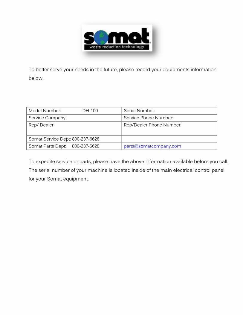
To better serve your needs in the future, please record your equipments information below.
Model Number: DH-100 Serial Number: Service Company: Service Phone Number: Rep/ Dealer:
Rep/Dealer Phone Number:
Somat Service Dept: 800-237-6628 Somat Parts Dept: 800-237-6628 [email protected]
To expedite service or parts, please have the above information available before you call. The serial number of your machine is located inside of the main electrical control panel for your Somat equipment.
SOMAT COMPANY LIMITED WARRANTY
SOMAT COMPANY warrants each new product manufactured by it to be free from defects in material and workmanship under normal use and service, which does not include normal wear of parts, ("normal use and service", with respect to Pulpers, Presses, water Hydra-Extractors, Waste Handling and Processing Systems, shall mean the handling only of waste items of the types listed in the SOMAT® Quotation or Sales Order therefore and within the LIMITATIONS THEREIN set forth), its obligation under this warranty being limited to repairing or replacing any part or parts thereof, free of charge INCLUSIVE of labor to remove and replace, f.o.b. factory from which shipped, which shall, within one year from initial start-up of the SOMAT® System or from date of original installation of the product if not a system be returned to SOMAT® at the factory from which shipped, with transportation charges prepaid, and which SOMAT's examination shall disclose to its satisfaction to have been thus defective. This warranty shall not apply to any product or part which shall have been repaired or altered by any person not employed or retained by SOMAT®, so as in the judgment of SOMAT® to affect its operation and reliability, nor which has been installed, operated, or maintained contrary to SOMAT® OPERATION or PREVENTIVE MAINTENANCE INSTRUCTION MANUALS or to other written instructions or drawings approved by SOMAT®, nor which has been subject to misuse, negligence, or accident. This warranty shall not apply should the SOMAT® System be initially started up without a duly authorized SOMAT® representative present. EXCEPT AS HEREIN EXPRESSLY STATED, NO WARRANTY, EXPRESS, IMPLIED OR BY LAW, (INCLUDING BUT NOT LIMITED TO ANY IMPLIED WARRANTY OF MERCHANTABILITY OR FITNESS FOR A PARTICULAR PURPOSE), IS MADE BY SOMAT; AND IN ANY EVENT SOMAT’S LIABILITY, WHETHER IN CONTRACT, TORT, STRICT LIABILITY, OR UNDER ANY WARRANTY, OR OTHERWISE, SHALL NOT EXCEED THE PURCHASE PRICE RECEIVED BY IT AND SHALL IN NO EVENT INCLUDE ANY CONSEQUENTIAL, INCIDENTAL, PUNITIVE OR OTHER SPECIAL DAMAGES.
NO CHANGE IN THIS WARRANTY AND LIMITATION OF LIABILITY AND NO SUBSTITUTE THEREFORE (WHETHER INCORPORATED IN A PURCHASE ORDER OR OTHERWISE) SHALL BE EFFECTIVE UNLESS SPECIFICALLY SET FORTH IN A WRITTEN INSTRUMENT SIGNED BY AN OFFICER OF SOMAT®.
Rev. 02/10
!WARNING!
Customer action required!
All DH products require quarterly
bearing maintenance. Failure to
properly inspect the bearings and
automatic greaser may result in
premature failure and costly
downtime.
!WARNING!
Table of Contents: DH-100
Introduction…………………………………………………………………………….. Safety Instructions General Description & Definitions
Installation……………………………………………………………………………….. Quick Guide
Start-up…………………………………………………………………………………….. Forms & Lists Warranty Validation
Operation…………………………………………………………………………………
Cleaning & Maintenance………………………………………………. Maintenance Troubleshooting
Replacement Parts…………………………………………………………. Electrical Panel

Safety Precautions and Warnings
READ THE MANUAL COMPLETELY BEFORE ATTEMPTING TO OPERATE THE UNIT. HIGH VOLTAGE! DO NOT PERFORM ANY REPAIRS TO MOTORS OR CONTROL SYSTEMS
WITHOUT TURNING OFF THE MAIN POWER. ALWAYS TURN THE MAIN POWER OFF AND LET ALL MOTORS COME TO A STANDSTILL
BEFORE DOING ANY MAINTENANCE ADJUSTMENTS OR CLEANING OF THE UNIT. BEFORE STARTING, BE SURE ALL PERSONNEL ARE CLEAR OF MOVING PARTS. KNOW LOCATION AND FUNCTIONS OF ALL START/STOP BUTTONS AND SAFETY
SWITCHES. DURING PERIODIC MAINTENANCE, CHECK ALL SAFETY SWITCHES TO BE SURE THEY
ARE OPERATING PROPERLY. DO NOT REMOVE OR ALTER GUARDS. DO NOT REMOVE SAFETY LABELS. IF LABELS ARE MISSING OR DESTROYED, CONTACT
FACTORY FOR REPLACEMENT. DO NOT OBSTRUCT ELECTRICAL PANELS OR PUSH BUTTONS. GOOD HOUSEKEEPING IS THE MOST IMPORTANT SAFETY PROCEDURE. The unit shall be installed in accordance with national and local wiring regulations and all
applicable codes. The unit MUST be placed at least 8” from the wall DO NOT pull or alter power cord. Pulling and misuse of the power supply cord can result in
damage to the unit and cause electrical shock. Ensure the electrical cord is properly grounded. DO NOT place any materials on top of unit DO NOT use water to clean the unit, use an approved stainless equivalent. DO NOT alter the pre-programmed settings or disassemble the unit without first contacting
Somat Company. Failure to do so may result in a voided warranty. Turn off incoming power to unit and lockout breaker to perform any kind of maintenance or
cleaning. DO NOT open the input door during operation, it can cause odor issues and errors in the
automated control and operation. Ensure the unit and the area around the unit is clean. Proper maintenance of the unit is also
highly recommended. Please have ALL operators read this manual to ensure proper understanding of the unit and
its operation.

Safety Precautions and Warnings This equipment has locations which are hazardous and cause severe injury or death if warnings are not followed. Always turn off power before reaching into any unit! Maintenance to be performed by trained and authorized personnel.
This equipment has moveable lids protecting you from moving parts. Do not alter safety devices or guards. Do not reach into any part of the unit with the power turned on.
This equipment uses High Voltage! Only trained and authorized personnel should perform maintenance on the electrical components of this machine. This equipment has moving parts that can crush and cut. Do not alter safety devices or guards. Do not reach into any part of the unit with the power turned on.
Caution: Damage will occur to this equipment if unsafe objects are fed into the machine(s). Keep these items out of the machine(s) to avoid component failure and unwanted downtime. When in doubt, keep it out of the machine(s)!
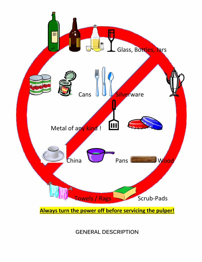
Glass, Bottles, Jars
Cans Silverware
Metal of any kind !
China Pans Wood
Towels / Rags Scrub-Pads
Always turn the power off before servicing the pulper!
GENERAL DESCRIPTION

The DH-100 is an automated on-site compostable waste dehydration system that dehydrates compostable waste using an energy-efficient and automated control process. The system requires no enzyme, additives or fresh water during the entirety of the dehydration process. The system is equipped with water recycling technology that uses the condensate runoff to control the humidity in the processing chamber during the process. The system also recycles the heat energy reducing overall energy consumption. The dehydration processing time will vary depending on the waste input but will be no longer than 24 hours. The system is equipped with an odor management device to control odors associated with the dehydration process. The one-touch control is fully automatic, sensing the status and providing feedback and control of the operation without pre-setting the timer.

Installation

UNPACKING
The crate containing your SOMAT® DH-100 will contain the following items:
DH-100 Condensate Hose 10’ of 10/4 SO Power Cord
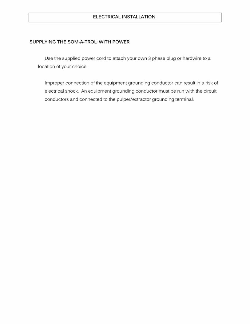
ELECTRICAL INSTALLATION
SUPPLYING THE SOM-A-TROL® WITH POWER
Use the supplied power cord to attach your own 3 phase plug or hardwire to a location of your choice.
Improper connection of the equipment grounding conductor can result in a risk of
electrical shock. An equipment grounding conductor must be run with the circuit conductors and connected to the pulper/extractor grounding terminal.
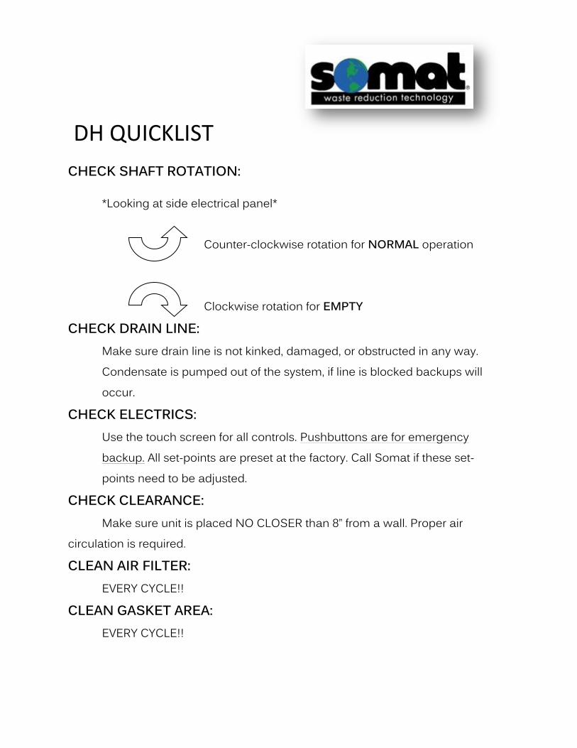
DH QUICKLIST
CHECK SHAFT ROTATION: *Looking at side electrical panel* Counter-clockwise rotation for NORMAL operation
Clockwise rotation for EMPTY
CHECK DRAIN LINE: Make sure drain line is not kinked, damaged, or obstructed in any way. Condensate is pumped out of the system, if line is blocked backups will occur.
CHECK ELECTRICS: Use the touch screen for all controls. Pushbuttons are for emergency backup. All set-points are preset at the factory. Call Somat if these set-points need to be adjusted.
CHECK CLEARANCE: Make sure unit is placed NO CLOSER than 8” from a wall. Proper air circulation is required.
CLEAN AIR FILTER: EVERY CYCLE!!
CLEAN GASKET AREA: EVERY CYCLE!!

Start Up

After installation is complete, your equipment will be started up by a qualified Somat service representative. This start up will get your unit running in accordance with Somat guidelines. The equipment may be demonstrated to you by the service company or the equipment rep themselves. The Somat equipment carries a 1 year warranty from date of start up. To accurately track this information, we ask that you fill out the Warranty Registration Sheet below and fax back to us. This will ensure your equipment is registered with Somat’s Service Department and will allow Somat’s Service Department to efficiently process a warranty claim if one should arise. You will also find copies of instructions for the equipment operators if the originally packaged laminated sheets are lost or damaged.
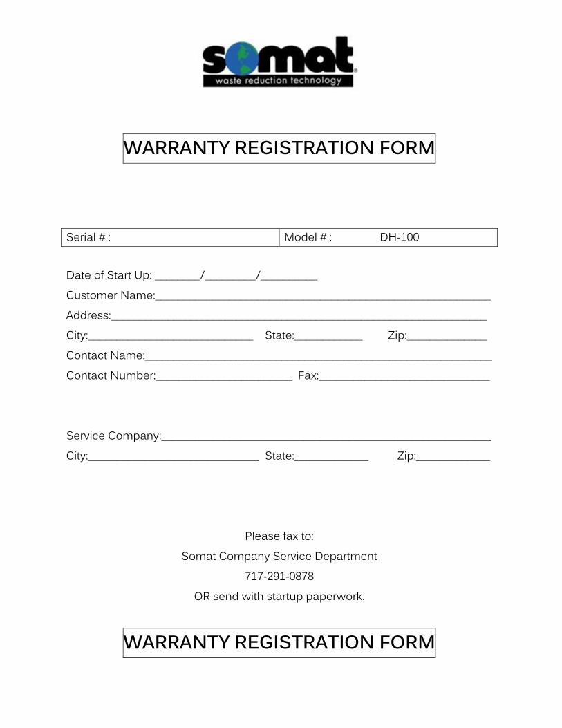
WARRANTY REGISTRATION FORM
Serial # : Model # : DH-100 Date of Start Up: ________/_________/__________ Customer Name:___________________________________________________________ Address:__________________________________________________________________ City:_____________________________ State:____________ Zip:______________ Contact Name:_____________________________________________________________ Contact Number:________________________ Fax:______________________________ Service Company:__________________________________________________________ City:______________________________ State:_____________ Zip:_____________
Please fax to: Somat Company Service Department
717-291-0878 OR send with startup paperwork.
WARRANTY REGISTRATION FORM

Operation
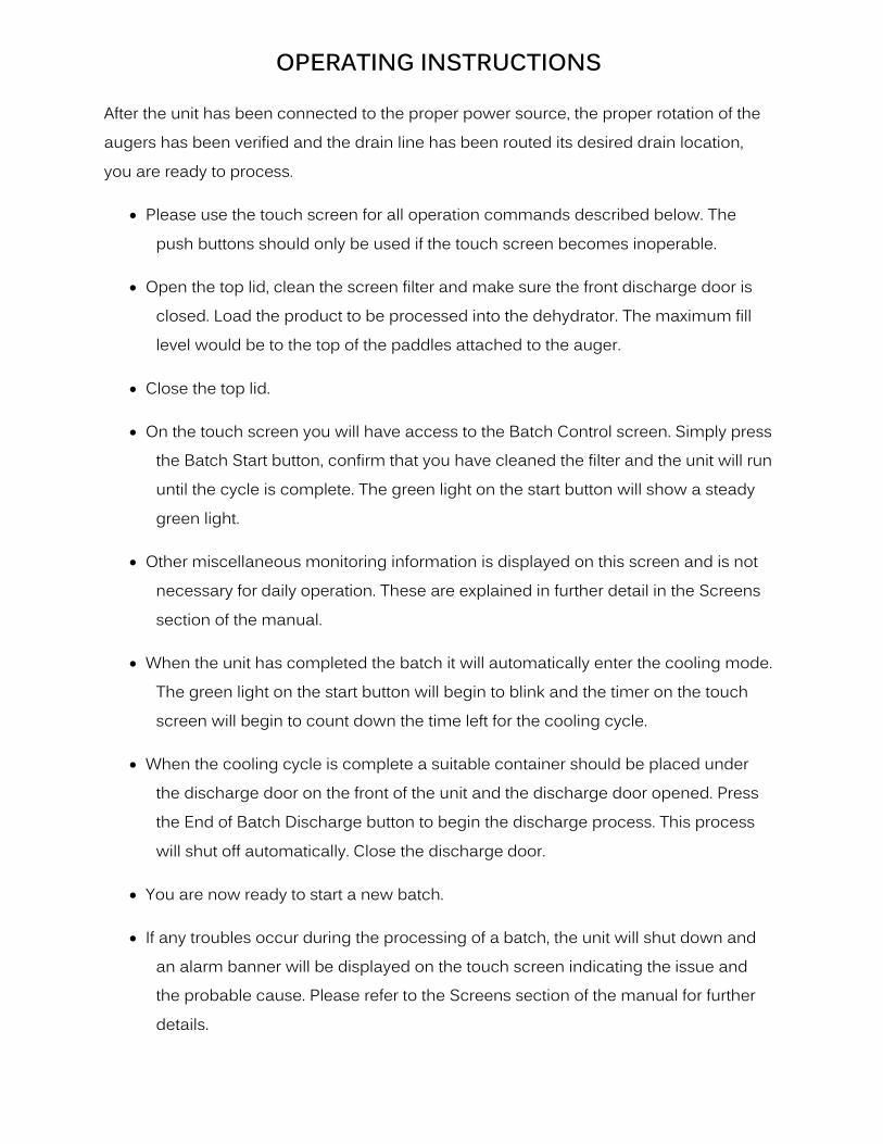
OPERATING INSTRUCTIONS
After the unit has been connected to the proper power source, the proper rotation of the augers has been verified and the drain line has been routed its desired drain location, you are ready to process.
Please use the touch screen for all operation commands described below. The push buttons should only be used if the touch screen becomes inoperable.
Open the top lid, clean the screen filter and make sure the front discharge door is closed. Load the product to be processed into the dehydrator. The maximum fill level would be to the top of the paddles attached to the auger.
Close the top lid.
On the touch screen you will have access to the Batch Control screen. Simply press the Batch Start button, confirm that you have cleaned the filter and the unit will run until the cycle is complete. The green light on the start button will show a steady green light.
Other miscellaneous monitoring information is displayed on this screen and is not necessary for daily operation. These are explained in further detail in the Screens section of the manual.
When the unit has completed the batch it will automatically enter the cooling mode. The green light on the start button will begin to blink and the timer on the touch screen will begin to count down the time left for the cooling cycle.
When the cooling cycle is complete a suitable container should be placed under the discharge door on the front of the unit and the discharge door opened. Press the End of Batch Discharge button to begin the discharge process. This process will shut off automatically. Close the discharge door.
You are now ready to start a new batch.
If any troubles occur during the processing of a batch, the unit will shut down and an alarm banner will be displayed on the touch screen indicating the issue and the probable cause. Please refer to the Screens section of the manual for further details.

DH-100 OPERATION INSTRUCTIONS
The DH-100 is designed to be operated by use of the touch screen panel. Use of the pushbuttons is only if the touch screen becomes inoperable.
To Start a New Batch:
Close discharge door. Open top lid, clean screen filter, Load
product into the DH-100. Maximum fill level is at the top of the paddles attached to center shaft.
Close top lid. Press BATCH START on the touch screen
Cooling Cycle:
When batch is complete, unit will automatically enter cooling mode. The green pushbutton will blink and the timer on the touch screen will begin to countdown to cycle completion.
End of Batch Discharge:
After the cooling cycle is complete, place a suitable container under the discharge door.
Open discharge door. Press End of Batch Discharge button on the touch screen. Unit will shut off automatically.
Process a New Batch…

MAINTENANCE

PERIODIC MAINTENANCE AND INSPECTION
These procedures consist primarily of regularly scheduled cleaning and inspections. The time intervals cited are based on normal use of the SOMAT unit; approximately one cycle per day, five days per week. Equipment operating more than this or in severe service will require more frequent inspection/maintenance.
Continued adherence to these inspections will provide adequate lead time when ordering spare parts, thereby minimizing unnecessary and costly equipment downtime.
PREVENTIVE MAINTENANCE INSPECTION SCHEDULE
DH-100 DAILY WEEKLY MONTHLY QUARTERLY
1. GENERAL
a. Check shell and chamber for wear.
X
b. Check exterior finish for corrosion.
X
2. Drive
a. Check seals for leakage X
b. Check bearings for noise & wear.
X
c. Check chain tension. X
d. Check auto-greaser capacity X
e. Check all door seals X X

COMPONENT REMOVAL AND REPLACEMENT - The following steps are required in the
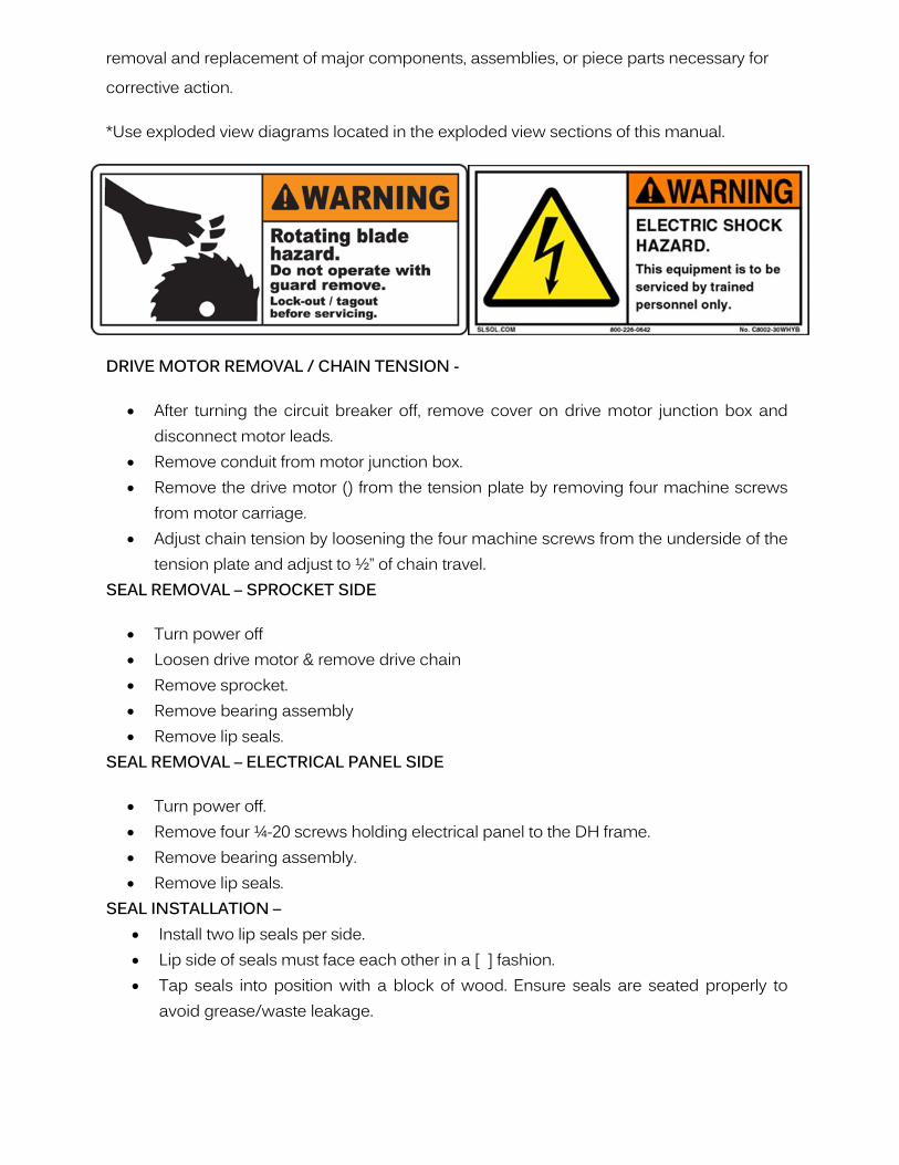
removal and replacement of major components, assemblies, or piece parts necessary for corrective action.
*Use exploded view diagrams located in the exploded view sections of this manual.
DRIVE MOTOR REMOVAL / CHAIN TENSION -
After turning the circuit breaker off, remove cover on drive motor junction box and disconnect motor leads.
Remove conduit from motor junction box. Remove the drive motor () from the tension plate by removing four machine screws
from motor carriage. Adjust chain tension by loosening the four machine screws from the underside of the
tension plate and adjust to ½” of chain travel. SEAL REMOVAL – SPROCKET SIDE
Turn power off Loosen drive motor & remove drive chain Remove sprocket. Remove bearing assembly Remove lip seals.
SEAL REMOVAL – ELECTRICAL PANEL SIDE
Turn power off. Remove four ¼-20 screws holding electrical panel to the DH frame. Remove bearing assembly. Remove lip seals.
SEAL INSTALLATION – Install two lip seals per side. Lip side of seals must face each other in a [ ] fashion. Tap seals into position with a block of wood. Ensure seals are seated properly to
avoid grease/waste leakage.

TROUBLESHOOTING

DeHydrator H.M.I. Screen Manual
Screen Name
Batch Control Screen Batch Control Screen (cont.) Auto & Time Only Feature Events & Alarms Main Menu Discharge Setpoints DeHydrator Temperatures Runtime Archives Heat Cycle Time Values Automatic/Delay Control Water Volume Track Lubrication Service Manual Control – 1 Manual Control -2 Service Screen – 1 Service Screen – 2
Banner Name Condensate Level Control Alarm
Emergency Stop Alarm
Operational Reminder
Open Discharge Alarm
Open Top Lid Alarm
Tumbler Motor Overload
VAC Fuse Blown Alarm
VDC Fuse Blown Alarm
Blower Motor/Condensate Fan Alarm
No Condensate
Condensate Sump High

Batch Control Screen
Button Function:
Batch Start – Starts a new batch after the last batch has been discharged or resumes the current
batch after a paused batch or an alarmed event.
Batch Pause – Pauses the current batch – will be restarted at current settings when the Batch
Start button is pressed.
Discharge Start/Pause – After opening the discharge chute, pressing this button starts the
discharge of a completed batch and resets the controls to begin a new batch. The discharge will
run for a preprogrammed period of time or the button can be pressed again to pause the
discharge.
Alarm Screen – Brings up the alarm screen where the time and type of alarm has been logged
Reset System – To abort a cycle or to reset an interrupted cycle when the unit has cooled down,
the controls can be reset with the following steps. With the unit in a non-running state (pause
batch if it is running), press and hold this button for 5 seconds. When released, you will be
prompted to confirm that you want to reset the batch. Confirming will reset the batch to the
beginning.
Auto & Time Only – This feature is used to override the condensation system in the event of a
condensate pump failure or a condensate level sensor failure. See next page for procedure.
Cooling indicator and duration timer- Shows the state of cooling and if in the cooling mode the
countdown timer shows the duration of time left till cooling is complete.

Batch Control Screen (continued)
Informational Sections:
Current Date and Time – This is used to log batch information into memory for various control
functions. This appears on all screens.
Tank, Oil and air temperature are actual temperatures displayed in deg F.
Batch Duration – Displays how long the current batch has been running or has run prior to
completing the cooling cycle.
Drain Cycles – Displays how many times the condensate collection tank has drained during the
current batch.
Accumulated Volume – Displays the current volume of water removed from the current batch
shown in ml x 10.
Present fill duration – Displays the live time that it is taking to fill the condensate collection
tank.

Auto & Time Only Feature
This feature is only used when there is a condensate pump or condensate system failure and the
dehydrator is in the process of running a batch. To properly finish a batch this feature will
continue the batch and bypass the condensate system until the fix is made. But, before any
changes are made on the batch control screen some hoses need to be reoriented in the back of
the dehydrator. First, remove rear panel which has holes in the stainless panel for the fans.
There will be a hose connected to the panel for condensate drain. See Picture A as how the
hoses should be hooked up under normal operation. Adjust the rear panel so that the top of the
panel can rest on the DH-100W tank. Then, locate on the condensate tank two elbow fittings
welded to the tank. Remove the hose the top fitting. Then, locate the plastic tee that is just
above those fittings. Remove the hose from the left side of the tee connection. Then, place that
lose end in the top fitting on the condensate tank which, should have no hose connected to.
Then, the lose hose from the bottom fitting connect to the rear panel. See pictures to represent.
PICTURE A
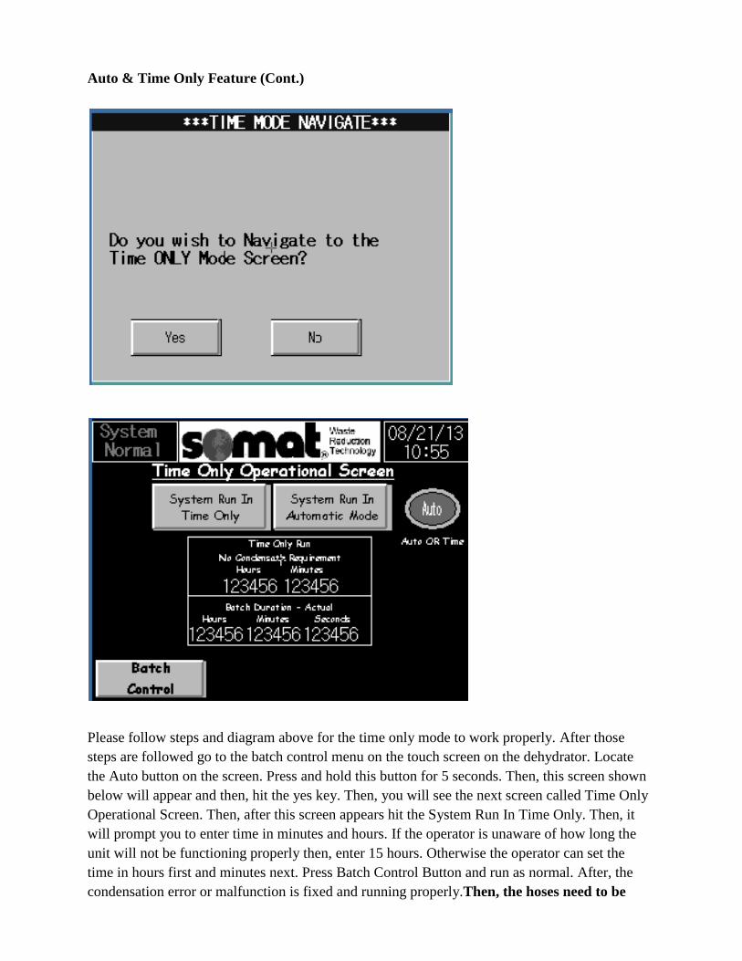
Auto & Time Only Feature (Cont.)
Please follow steps and diagram above for the time only mode to work properly. After those
steps are followed go to the batch control menu on the touch screen on the dehydrator. Locate
the Auto button on the screen. Press and hold this button for 5 seconds. Then, this screen shown
below will appear and then, hit the yes key. Then, you will see the next screen called Time Only
Operational Screen. Then, after this screen appears hit the System Run In Time Only. Then, it
will prompt you to enter time in minutes and hours. If the operator is unaware of how long the
unit will not be functioning properly then, enter 15 hours. Otherwise the operator can set the
time in hours first and minutes next. Press Batch Control Button and run as normal. After, the
condensation error or malfunction is fixed and running properly.Then, the hoses need to be

switched back to their original location for the machine to function and run a batch
properly. This is a very important step.
Then, after this step is complete go back to the batch control screen. This time we want to
switch back to Auto Run. So, on the batch control screen the button will read time instead of
Auto. To revert back to Auto Run, press and hold this button for 5 seconds. Then, the Time
Only Operational Screen will appear. After, this screen appears hit the System Run in
Automatic Mode button and it will revert back to Auto Run. Then, Press the Batch Control
Button, and run batch as normal.
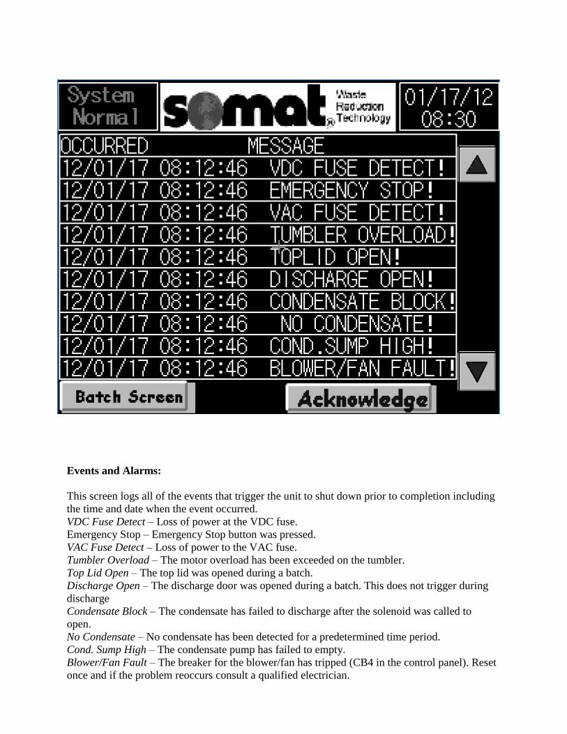
Events and Alarms:
This screen logs all of the events that trigger the unit to shut down prior to completion including
the time and date when the event occurred.
VDC Fuse Detect – Loss of power at the VDC fuse.
Emergency Stop – Emergency Stop button was pressed.
VAC Fuse Detect – Loss of power to the VAC fuse.
Tumbler Overload – The motor overload has been exceeded on the tumbler.
Top Lid Open – The top lid was opened during a batch.
Discharge Open – The discharge door was opened during a batch. This does not trigger during
discharge
Condensate Block – The condensate has failed to discharge after the solenoid was called to
open.
No Condensate – No condensate has been detected for a predetermined time period.
Cond. Sump High – The condensate pump has failed to empty.
Blower/Fan Fault – The breaker for the blower/fan has tripped (CB4 in the control panel). Reset
once and if the problem reoccurs consult a qualified electrician.

Each button when pressed will take you to a screen with options to control that particular
function.

Discharge Setpoints:
Shutoff Setpoint – Sets the duration that the discharge mode runs before shutting off
automatically.
Accumulated Value – This is a live timer showing the actual time of current discharge.
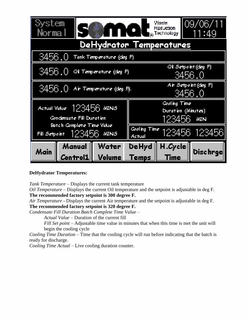
DeHydrator Temperatures:
Tank Temperature – Displays the current tank temperature
Oil Temperature – Displays the current Oil temperature and the setpoint is adjustable in deg F.
The recommended factory setpoint is 300 degree F. Air Temperature - Displays the current Air temperature and the setpoint is adjustable in deg F.
The recommended factory setpoint is 320 degree F.
Condensate Fill Duration Batch Complete Time Value –
Actual Value – Duration of the current fill
Fill Set point – Adjustable time value in minutes that when this time is met the unit will
begin the cooling cycle
Cooling Time Duration – Time that the cooling cycle will run before indicating that the batch is
ready for discharge.
Cooling Time Actual – Live cooling duration counter.
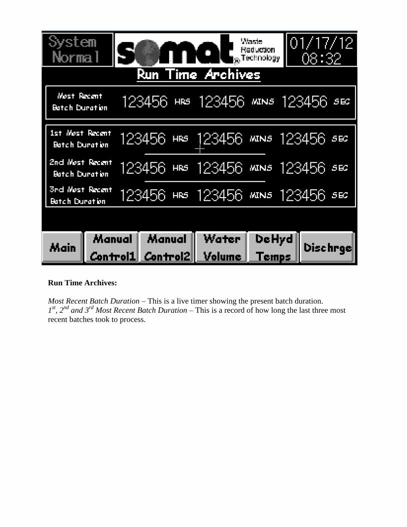
Run Time Archives:
Most Recent Batch Duration – This is a live timer showing the present batch duration.
1st, 2
nd and 3
rd Most Recent Batch Duration – This is a record of how long the last three most
recent batches took to process.

Heat Cycle Time Values:
Air Heat Duration – Indicates the total time that the air heater has been running during the
current batch.
Air Heat Cycles – Indicates how many times the air heater has cycled during the current batch
Oil Heat Duration - Indicates the total time that the oil heaters have been running during the
current batch.
Oil Heat Cycles - Indicates how many times the oil heaters have cycled during the current batch

Automatic/Delay Control:
This is an option designed for use at the SOMAT factory.
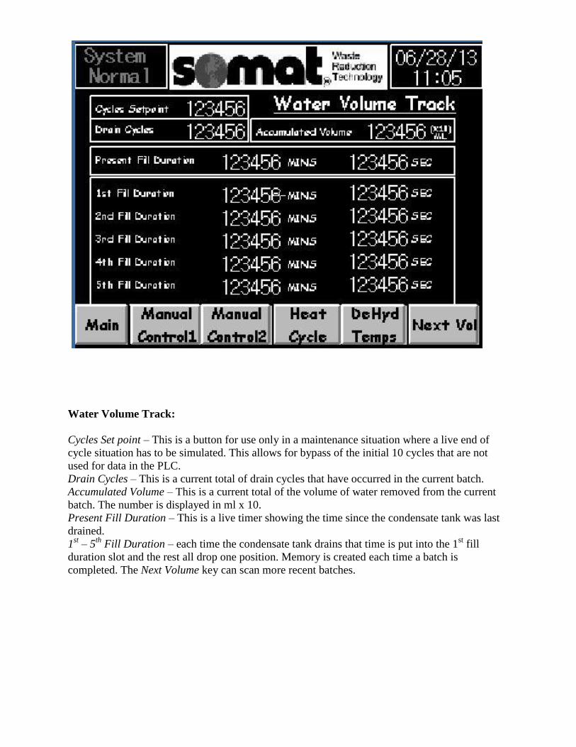
Water Volume Track:
Cycles Set point – This is a button for use only in a maintenance situation where a live end of
cycle situation has to be simulated. This allows for bypass of the initial 10 cycles that are not
used for data in the PLC.
Drain Cycles – This is a current total of drain cycles that have occurred in the current batch.
Accumulated Volume – This is a current total of the volume of water removed from the current
batch. The number is displayed in ml x 10.
Present Fill Duration – This is a live timer showing the time since the condensate tank was last
drained.
1st – 5
th Fill Duration – each time the condensate tank drains that time is put into the 1
st fill
duration slot and the rest all drop one position. Memory is created each time a batch is
completed. The Next Volume key can scan more recent batches.

Reset Lubrication Injector Count – This button should be pressed when the grease cartridge has
been changed. This will restart the counter that tracks the greaser and displays a warning when
the cartridge needs to be replaced.
Number of Lubrication Injections – Live count of how many times the greaser has dispensed a
shot of grease from the current cartridge.
Batch Completions – Total number of batches completed.
Accumulated Hours Since Last Lubrication – Live counter of running hours since the last time
the greaser was activated.
Lubrication Duration Setpoint – Adjustable setpoint that, when this time is reached, calls for the
greaser to lubricate the bearings.
Manual Lubricate Start/Stop – These buttons can be used to manually operate the greaser.
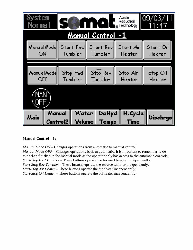
Manual Control – 1:
Manual Mode ON – Changes operations from automatic to manual control
Manual Mode OFF – Changes operations back to automatic. It is important to remember to do
this when finished in the manual mode as the operator only has access to the automatic controls.
Start/Stop Fwd Tumbler – These buttons operate the forward tumbler independently.
Start/Stop Rev Tumbler – These buttons operate the reverse tumbler independently.
Start/Stop Air Heater – These buttons operate the air heater independently.
Start/Stop Oil Heater – These buttons operate the oil heater independently.

Manual Control – 2:
Manual Mode ON – Changes operations from automatic to manual control
Manual Mode OFF – Changes operations back to automatic. It is important to remember to do
this when finished in the manual mode as the operator only has access to the automatic controls.
Start/Stop Discharge – These buttons operate the discharge mode independently.
Start/Stop Blower Motor – These buttons operate the blower motor independently.
Start/Stop Cond. Heater – These buttons operate the condensate heater independently. (If
equipped on unit)
Condensate Pump ON/OFF – These buttons allow for independent control of the condensate
pump.
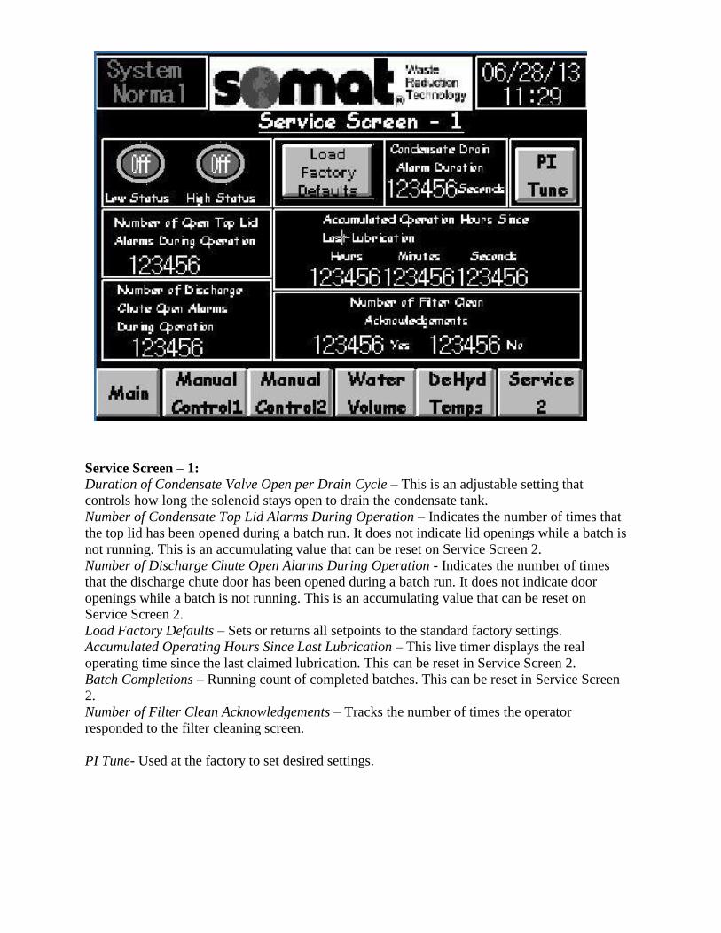
Service Screen – 1:
Duration of Condensate Valve Open per Drain Cycle – This is an adjustable setting that
controls how long the solenoid stays open to drain the condensate tank.
Number of Condensate Top Lid Alarms During Operation – Indicates the number of times that
the top lid has been opened during a batch run. It does not indicate lid openings while a batch is
not running. This is an accumulating value that can be reset on Service Screen 2.
Number of Discharge Chute Open Alarms During Operation - Indicates the number of times
that the discharge chute door has been opened during a batch run. It does not indicate door
openings while a batch is not running. This is an accumulating value that can be reset on
Service Screen 2.
Load Factory Defaults – Sets or returns all setpoints to the standard factory settings.
Accumulated Operating Hours Since Last Lubrication – This live timer displays the real
operating time since the last claimed lubrication. This can be reset in Service Screen 2.
Batch Completions – Running count of completed batches. This can be reset in Service Screen
2.
Number of Filter Clean Acknowledgements – Tracks the number of times the operator
responded to the filter cleaning screen.
PI Tune- Used at the factory to set desired settings.
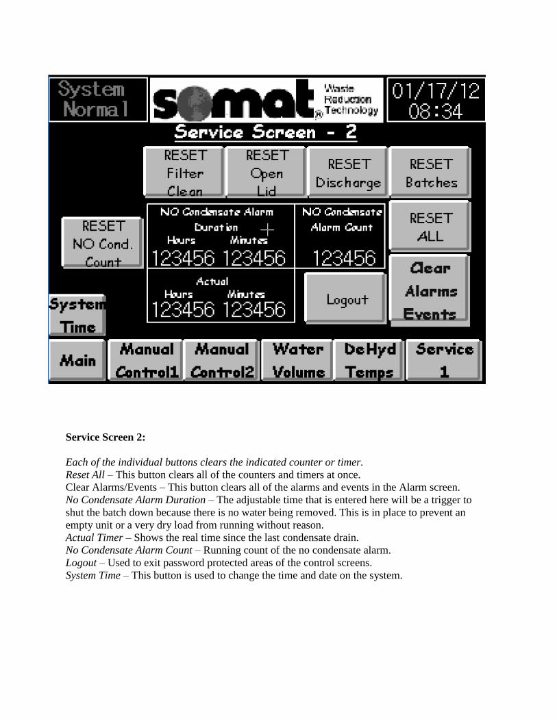
Service Screen 2:
Each of the individual buttons clears the indicated counter or timer.
Reset All – This button clears all of the counters and timers at once.
Clear Alarms/Events – This button clears all of the alarms and events in the Alarm screen.
No Condensate Alarm Duration – The adjustable time that is entered here will be a trigger to
shut the batch down because there is no water being removed. This is in place to prevent an
empty unit or a very dry load from running without reason.
Actual Timer – Shows the real time since the last condensate drain.
No Condensate Alarm Count – Running count of the no condensate alarm.
Logout – Used to exit password protected areas of the control screens.
System Time – This button is used to change the time and date on the system.
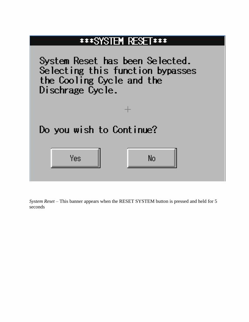
System Reset – This banner appears when the RESET SYSTEM button is pressed and held for 5
seconds
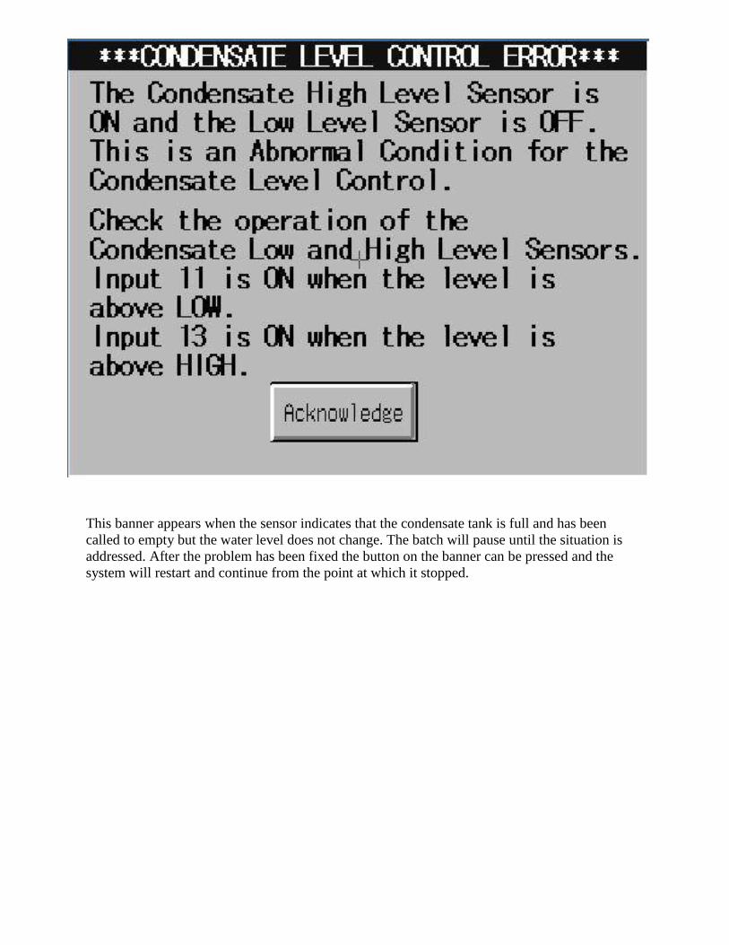
This banner appears when the sensor indicates that the condensate tank is full and has been
called to empty but the water level does not change. The batch will pause until the situation is
addressed. After the problem has been fixed the button on the banner can be pressed and the
system will restart and continue from the point at which it stopped.
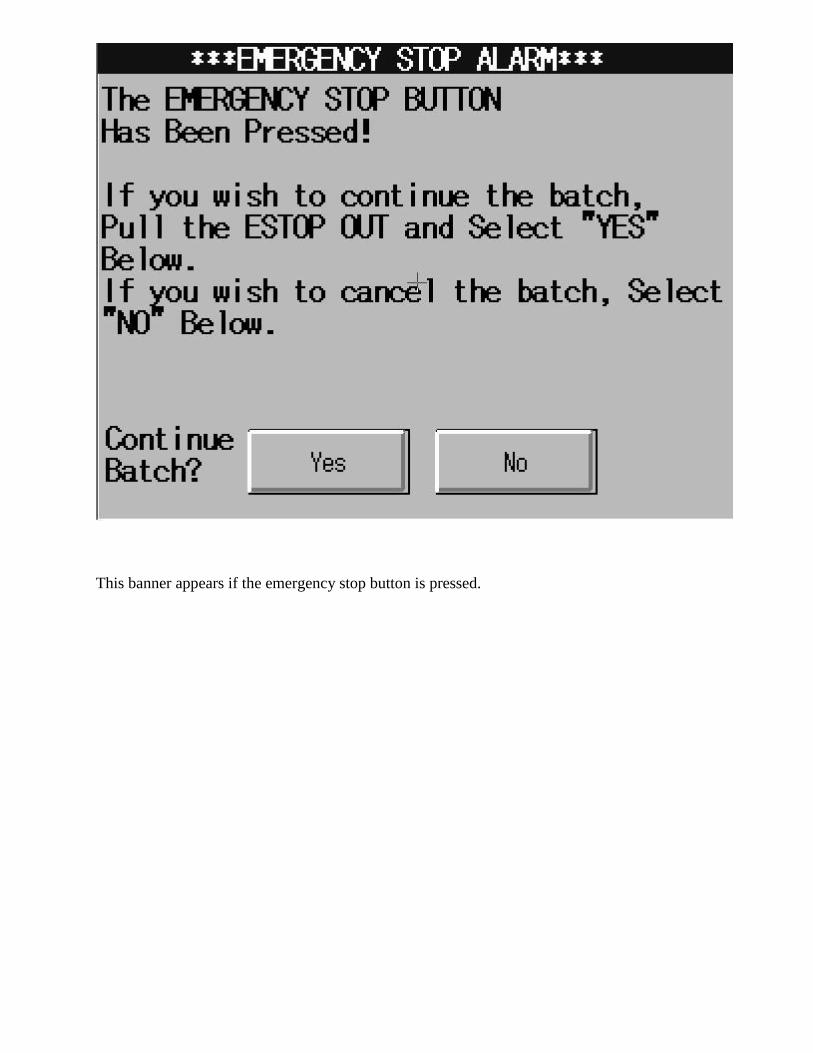
This banner appears if the emergency stop button is pressed.
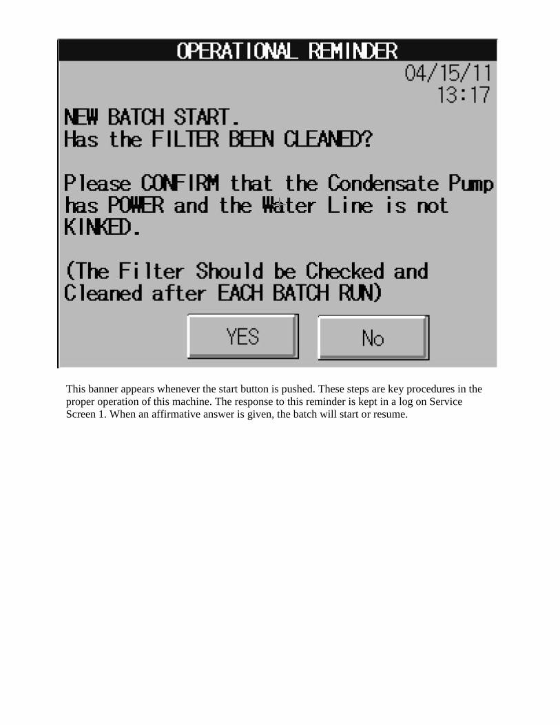
This banner appears whenever the start button is pushed. These steps are key procedures in the
proper operation of this machine. The response to this reminder is kept in a log on Service
Screen 1. When an affirmative answer is given, the batch will start or resume.

This banner appears when the discharge door is opened during normal operation. The unit will
shut down with this alarm. The door must be shut and then the batch can resume by pressing the
yes button.

This banner appears when the top lid is opened during normal operation. The unit will shut
down with this alarm. The lid must be shut and then the batch can resume by pressing the yes
button.
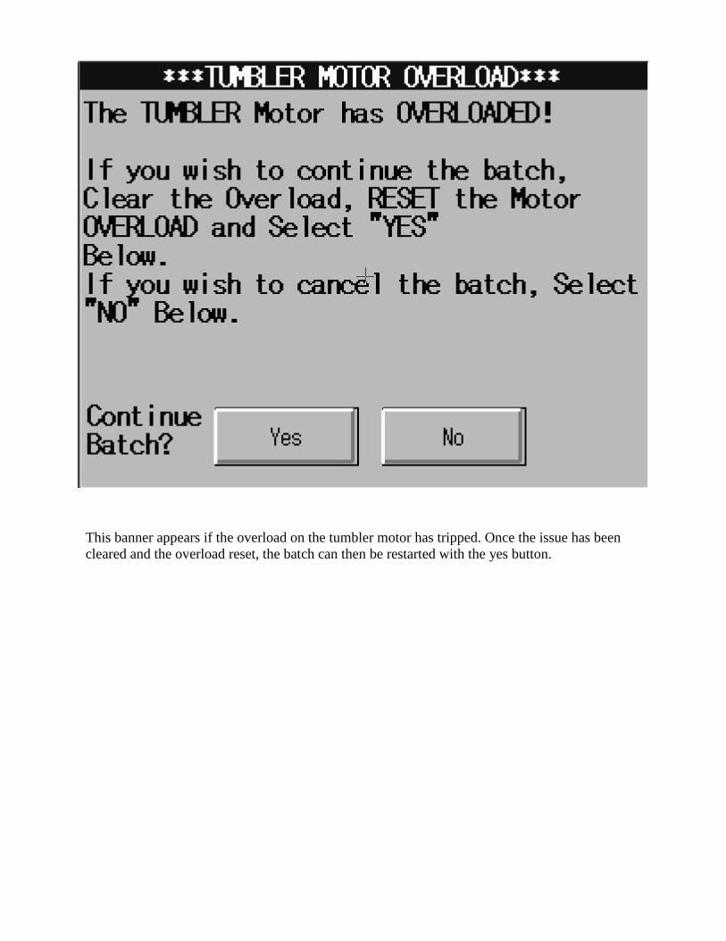
This banner appears if the overload on the tumbler motor has tripped. Once the issue has been
cleared and the overload reset, the batch can then be restarted with the yes button.

This banner appears if the VAC fuse has no signal. This indicates a blown fuse. Replace the
fuse and restart with the acknowledge button. If the situation reoccurs, contact a qualified
electrician.

This banner appears if the VDC fuse has no signal. This indicates a blown fuse. Replace the
fuse and restart with the acknowledge button. If the situation reoccurs, contact a qualified
electrician.

This banner indicates a tripped breaker in the control panel for the fans. Reset once and if the
problem reoccurs contact a qualified electrician.

This banner appears when a new batch has been started but no condensate is being detected in
the condensate tank. The alarm occurs after a predetermined waiting period. This time is set at 3
hours from the factory. This can be caused by dry product in the unit, improper heating of the
unit or failure of the level sensor.

This banner appears when the condensate pump fails to pump and the sump fills up causing the
back-up alarm to trigger. This will occur if the pump fails, or the pump power supply is lost, or
the discharge line from the pump is blocked or kinked.

Air Temperature Thermocouple – This banner appears when the thermocouple connection is
lost for the air temperature.

Oil Temperature Thermocouple – This banner appears when the thermocouple connection is
lost for the oil temperature.

Tank Temperature Thermocouple – This banner appears when the thermocouple connection is
lost for the tank temperature.

REPLACEMENT PARTS & EXPLODED VIEWS


DH-100 MECHANICAL PARTS LIST Description Part Number Required Chain, roller ET100-CHML 1
Pump, condensate ET100-CP 1 Grease Cup, Auto greaser ET100-GR-PLC 1
Replacement cartridge, grease cup
ET100-GRCART-PLC 1
Motor Mount ET100-MM 1 Step Key ET100-SK 1
Flush mount guard ET100-FMG 1 Tank, Weldment ET100-TWBF 1 Bottom Frame ET100-BTMF 1
Casters ET100-CAST 4
Items not shown in exploded views.
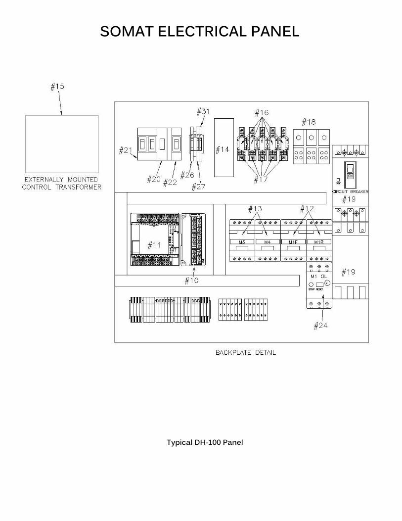
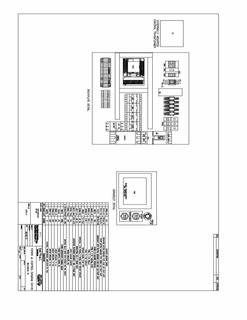
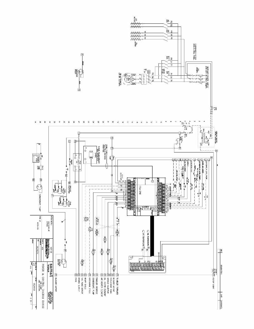
SOMAT ELECTRICAL PANEL
Typical DH-100 Panel

Typical DH-100 Consolet
Figure & Item # Description Part Number Required 1 Enclosure, Consolet 28361 1 2 Enclosure, Window 28362 1
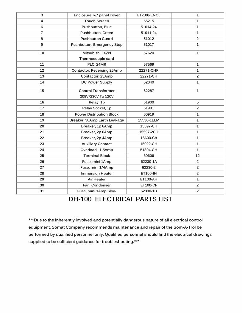
DH-100 ELECTRICAL PARTS LIST
***Due to the inherently involved and potentially dangerous nature of all electrical control equipment, Somat Company recommends maintenance and repair of the Som-A-Trol be performed by qualified personnel only. Qualified personnel should find the electrical drawings supplied to be sufficient guidance for troubleshooting.***
3 Enclosure, w/ panel cover ET-100-ENCL 1 4 Touch Screen 65215 1 6 Pushbutton, Blue 51014-24 1 7 Pushbutton, Green 51011-24 1 8 Pushbutton Guard 51012 2 9 Pushbutton, Emergency Stop 51017 1
10 Mitsubishi FXZN Thermocouple card
57620 1
11 PLC, 24MR 57569 1 12 Contactor, Reversing 25Amp 22271-CHR 1 13 Contactor, 25Amp 22271-CH 2 14 DC Power Supply 62340 1
15 Control Transformer 208V/230V To 120V
62287 1
16 Relay, 1p 51900 5 17 Relay Socket, 1p 51901 2 18 Power Distribution Block 60919 1 19 Breaker, 30Amp Earth Leakage 15530-1ELM 1 20 Breaker, 1p 6Amp 15597-CH 1 21 Breaker, 2p 6Amp 15597-2CH 1 22 Breaker, 2p 4Amp 15600-Ch 1 23 Auxiliary Contact 15022-CH 1 24 Overload , 1-5Amp 51894-CH 1 25 Terminal Block 60606 12 26 Fuse, mini 1Amp 62230-1A 2 27 Fuse, mini 1/4Amp 62230-2 2 28 Immersion Heater ET100-IH 2 29 Air Heater ET100-AH 1 30 Fan, Condenser ET100-CF 2 31 Fuse, mini 1Amp Slow 62330-1B 2