operator manual firmware version 6.3 ag leader pn … · smart report auto-generation ... software...
TRANSCRIPT

Operator Manual
Firmware Version 6.3
Ag Leader PN 4002083-ENG Rev. O

© 2015 Ag Leader Technology2202 South Riverside Drive
Ames, Iowa 50010 USAAll Rights Reserved
Firmware Version 6.3
TA
BL
E O
F C
ON
TE
NT
S
Table of ContentsGeneral
About this ManualIntroduction and Company Profile ............................................................................1Display......................................................................................................................1Service......................................................................................................................1System Uses ............................................................................................................2System Features ......................................................................................................2USB Flash Drive .......................................................................................................3Color Touch Screen..................................................................................................3CAN BUS Technology ..............................................................................................3Technical Specifications ...........................................................................................3System and Upgrades ..............................................................................................3Automated Module Firmware Upgrade.....................................................................4Product Registration.................................................................................................4Conventions Used In This Manual............................................................................4Cautions and Warnings ............................................................................................4Cross-references and Web Links .............................................................................4Viewing this Manual Online ......................................................................................5How to Find Information You’re Looking For ............................................................5
InstallationDisplay Hardware .....................................................................................................7Installation Instructions.............................................................................................7Fuse Installation and Replacement ..........................................................................9Screen Icon Conventions .........................................................................................9
Setup
ConfigurationInitial Startup...........................................................................................................11
Advanced Options.............................................................................................11Location Specific Setup.....................................................................................12Single Display ...................................................................................................12Multiple Display Setup - First Display................................................................13Multiple Display Setup - Additional Display.......................................................14
Import Setup Data ..................................................................................................14Import Files .......................................................................................................14
Home Screen..........................................................................................................15Setup buttons .........................................................................................................16Display button.........................................................................................................16
General tab .......................................................................................................17
iii Ag Leader PN 4002083-ENG Rev. O

Display tab........................................................................................................ 18Features tab ..................................................................................................... 19
Unlocking Features ..................................................................................... 19Advanced tab.................................................................................................... 19
Configuration button............................................................................................... 21Configuration tab .............................................................................................. 21Product tab ....................................................................................................... 22
Planting Settings ......................................................................................... 23Application Settings..................................................................................... 23Grain Harvest Settings................................................................................ 23
Management SetupConfiguration Selection .................................................................................... 25
All Modules Detected............................................................................. 25Modules Missing .................................................................................... 25Some Modules Not Detected................................................................. 26Modules not the same as previously used............................................. 26
Events............................................................................................................... 26Setting mode (Traditional or Events Only) using Permissions .................... 27Starting an Event......................................................................................... 27Managing Events ........................................................................................ 28
Management button.......................................................................................... 30Grower/Farm/Field tab...................................................................................... 30
Grower ........................................................................................................ 30Farm and Field ............................................................................................ 31Importing and Exporting Field Boundaries .................................................. 32
Season tab ....................................................................................................... 33Users tab .......................................................................................................... 33
Add a User .................................................................................................. 34User Setup button ....................................................................................... 34
General tab............................................................................................ 35Phone/Email tab .................................................................................... 35Address tab............................................................................................ 35
Permissions ...................................................................................................... 35Operators .................................................................................................... 35 Managers ................................................................................................... 35
Permission Level For Operators....................................................................... 36Full Permission............................................................................................ 36Basic Permission......................................................................................... 36 Custom Permission .................................................................................... 37
Accessing Setup Menus................................................................................... 39Accessing USB................................................................................................. 39Forgotten Passwords........................................................................................ 40 Businesses tab ................................................................................................ 41
Field OperationsOperator Selection............................................................................................ 43Operator Log Out.............................................................................................. 44
Configuration Setup Screen................................................................................... 44
iv Firmware Version 6.3
TA
BL
E O
F C
ON
TE
NT
S
Setup Event ............................................................................................................45Field Finder .......................................................................................................46Field Operation Options ....................................................................................46
Run screens ...........................................................................................................47GPS Signal Indicator.........................................................................................49Mapping Toolbox...............................................................................................51
Map Legend tab...........................................................................................51Map Options ................................................................................................51
Legend Settings .....................................................................................52Markers tab..................................................................................................53
Edit Markers ...........................................................................................54Field Tab......................................................................................................54
Boundary ................................................................................................54Boundary Settings ..................................................................................55Create Boundary ....................................................................................55Pause Boundary.....................................................................................56
Headlands.........................................................................................................56Active Area ..................................................................................................56Add a Headland...........................................................................................57
Headland Types .....................................................................................57Load Headlands...........................................................................................58Edit Headlands ............................................................................................59Headland Alarm Settings.............................................................................59
Topography ............................................................................................60Setup Map Screen..................................................................................60
Video.................................................................................................................63
ReportsSummary Report ....................................................................................................65
Date Range.......................................................................................................67Field Notes........................................................................................................67
Smart Report™.......................................................................................................68Create Reports..................................................................................................69Smart Report Auto-Generation .........................................................................69Control Channel Report Content.......................................................................71View Reports.....................................................................................................72View Map ..........................................................................................................72
External DriveExternal Storage Operations ..................................................................................73
Upgrade Firmware ............................................................................................73Import Files .......................................................................................................73
.AGSETUP...................................................................................................73
.AGDATA.....................................................................................................74Export Files .......................................................................................................74
.AGSETUP...................................................................................................74
.AGDATA.....................................................................................................74Export Reports.............................................................................................75
Manage Files.....................................................................................................75
v Ag Leader PN 4002083-ENG Rev. O
Advanced Options ............................................................................................ 75
DevicesDevice Information ................................................................................................. 77
Devices............................................................................................................. 77Display Diagnostics .......................................................................................... 77
SettingsEquipment Settings................................................................................................ 79
Implement Switch Settings (for Area Logging)............................................ 79Equipment Configuration Settings for Rate Control .................................... 80
Speed Input Settings.............................................................................................. 80Calibrate Distance ............................................................................................ 81
Auxiliary Input ........................................................................................................ 82Auxiliary Input Settings..................................................................................... 83Auxiliary Input: Help.......................................................................................... 83Auxiliary Input Diagnostics ............................................................................... 83
AutoSwath.............................................................................................................. 84Look-Ahead Settings................................................................................... 85
Vehicle Offsets....................................................................................................... 85Antenna Offsets tab.......................................................................................... 86Hitch Tab Settings tab ...................................................................................... 86Mount Tab Settings (for some Application vehicles) ........................................ 86Head Tab (for Harvest vehicles)....................................................................... 86Swath Section Offsets ...................................................................................... 86
Section Offsets............................................................................................ 87
Virtual TerminalCommon Terminology............................................................................................ 89Auxiliary Assignment.............................................................................................. 91VT Alarms and Trouble Codes............................................................................... 92Task Controller....................................................................................................... 93Configuration Setup ............................................................................................... 93ISOBUS Settings ................................................................................................... 94
AgFinitiConnecting to Wi-Fi Network ................................................................................. 95Connecting to AgFiniti............................................................................................ 96File Transfer........................................................................................................... 97
Importing and Exporting Files........................................................................... 97Viewing Files .................................................................................................... 97Export Settings ................................................................................................. 98Importing a Prescription.................................................................................... 99Importing a Variety Reference Map (Harvest Only)........................................ 100
Remote Support................................................................................................... 100Remote Support Permissions Options ........................................................... 100
GPS
vi Firmware Version 6.3
TA
BL
E O
F C
ON
TE
NT
S
GPSGPS Button...........................................................................................................103Setup ....................................................................................................................103Serial GPS Settings..............................................................................................103
Differential Source...........................................................................................105WAAS/EGNOS Settings ............................................................................105TerraStar Settings......................................................................................106RTK External Settings ...............................................................................107RTK Settings - NTRIP................................................................................107RTK Settings - 900/400 MHz.....................................................................109
Upgrade Receiver.................................................................................................110Serial Port Settings...............................................................................................111Port A tab..............................................................................................................111Port B tab..............................................................................................................111GPS Information ...................................................................................................112
GPS Information - General Tab ......................................................................113GPS Messages..........................................................................................114
Satellite Plot ....................................................................................................115GPS Information - Receiver Tab.....................................................................115GPS Information - Differential Tab ..................................................................116GPS Information - OmniSTAR Tab.................................................................117
RTK/NTRIP Information (ParaDyme/GeoSteer Only)................................117GPS Information - NTRIP................................................................................118
OmniSTAR Settings .............................................................................................118OmniSTAR Settings — GPS 2500 .......................................................................120
GPS Information for 2500 RTK .......................................................................1212500 RTK Setup..............................................................................................122
Guidance
GuidanceGuidance/Steering Control ...................................................................................125Setup ....................................................................................................................125Lightbar Settings...................................................................................................126Setup ....................................................................................................................126Guidance Tab on Mapping Toolbox .....................................................................126New Pattern..........................................................................................................127
Straight............................................................................................................127Select Pattern ............................................................................................127Create AB line using 2 points ....................................................................127Create AB line using Current Location and Heading.................................127Create AB line using Current Location and Inputting Heading ..................127
Adaptive Curve................................................................................................128Select Pattern ............................................................................................128Create AB line using 2 points ....................................................................128
Identical Curve ................................................................................................129Select Pattern ............................................................................................129
vii Ag Leader PN 4002083-ENG Rev. O
Create AB line using 2 points.................................................................... 130Pivot................................................................................................................ 130
Select Pattern............................................................................................ 131Create AB line using driven path............................................................... 131
SmartPath....................................................................................................... 132Select SmartPath ...................................................................................... 132Inputting Paths into SmartPath ................................................................. 133Cycle between Loaded Paths ................................................................... 133Select a Previous SmartPath Pass ........................................................... 134SmartPath Guidance Options ................................................................... 134
AutoSave ............................................................................................................. 135Manage Patterns.................................................................................................. 136Spatial Sort .......................................................................................................... 136
Import Pattern................................................................................................. 136Export Pattern................................................................................................. 136Edit Pattern..................................................................................................... 136Remove Pattern/Remove All Patterns............................................................ 137Reset Pattern.................................................................................................. 137
Pattern Groups..................................................................................................... 137Guidance Options ................................................................................................ 138
Save ............................................................................................................... 138Pause ............................................................................................................. 139Remark A........................................................................................................ 139Nudge............................................................................................................. 139Shift ................................................................................................................ 140Steering .......................................................................................................... 141OnTrac Tuning................................................................................................ 141Lightbar........................................................................................................... 142Tramlines........................................................................................................ 142
OnTrac2+AutoSteer Setup Screen ...................................................................................... 145Vehicle ................................................................................................................. 146
Setup Wizard .................................................................................................. 146Manage Vehicle.............................................................................................. 147Select.............................................................................................................. 147Edit ................................................................................................................. 148Delete ............................................................................................................. 148Export/Import .................................................................................................. 148
Export profile to a USB drive ............................................................... 149Import profile to a USB drive................................................................ 149
Auto Calibrate ...................................................................................................... 149Adjust Lateral Offset.................................................................................. 150
Steering Adjust ............................................................................................... 151Steering Components..................................................................................... 152
OnTrac2 ECU............................................................................................ 152Manual Steering Override ......................................................................... 152Remote Engage Switch............................................................................. 152MDU.......................................................................................................... 152
viii Firmware Version 6.3

TA
BL
E O
F C
ON
TE
NT
S
System Menu........................................................................................................153System Health.................................................................................................153Manage Settings .............................................................................................154
Log Files ....................................................................................................154Database ...................................................................................................155Reset Factory Default ................................................................................155
Accessories.....................................................................................................155Technician.......................................................................................................156Software Upgrade ...........................................................................................156
GPS Diagnostics ..................................................................................................156Details...................................................................................................................157
TillageCreate Tillage Configuration.................................................................................159Configuration Setup..............................................................................................159
Load Configuration..........................................................................................160Run Configuration.................................................................................................160
Planting
Create Planting ConfigurationCreate Equipment Configuration ..........................................................................163
AutoSwathRow Shutoff ..........................................................................................................167
Configuration Setup ........................................................................................167Row Shutoff Look-Ahead Numbers.................................................................167
Automatic AutoSwath Control...............................................................................168Look-Ahead Settings .................................................................................168
Checking AutoSwath Performance for Row Shutoff .......................................169Fixing Overplanting and Underplanting in AutoSwath.....................................170
Rate ControlHydraulic Seed Rate Control ................................................................................171
Controller Settings for Hydraulic Seed Rate Motor Drives ..............................171Channel Tab settings.................................................................................172
Control Valve Settings - PWM..............................................................172Control Valve Settings - Servo .............................................................173
Auxiliary Tab settings.................................................................................173Hydraulic Seed Controller Settings for Specific Planters ................................174Hydraulic Seed Meter Calibration Numbers....................................................175
Stepper Seed Rate Control ..................................................................................176Controller Settings for Stepper Seed Rate Motor Drives ................................176
Channel Tabs ............................................................................................177Auxiliary Tab..............................................................................................177
Gear Ratio Calculations for Seed Rate Motors ...............................................178
ix Ag Leader PN 4002083-ENG Rev. O
Gear Ratio Drawing - For Single Motor Drive ........................................... 178Gear Ratio Drawing - For Multiple Drive Combinations ............................ 179Seed Ratio Calculation Example Procedure ............................................. 179Gear Ratio Drawing Shaft Drives .............................................................. 180
Planter Options Screen........................................................................................ 181Priming Seed Rate Meters................................................................................... 181Calibrating Seed Rate Meters.............................................................................. 182Rate Control: Map Screen ................................................................................... 183Product Control Toolbox ...................................................................................... 183
Rate Control Settings ..................................................................................... 184Loading Prescriptions .......................................................................................... 185
Showing Prescriptions on the Map Screen..................................................... 185Troubleshooting ................................................................................................... 186
Hydraulic Seed Control: Zero Flow Offset Variation....................................... 186Hydraulic Seed Control: Zero Flow Offset Variation....................................... 187Stepper Seed Control Meter Alarms............................................................... 187
Down ForceModes of Operation ............................................................................................. 189Create Equipment Configuration.......................................................................... 189Setup Down Force Configuration......................................................................... 190Calibrate Pressure Sensor................................................................................... 192Down Force Status .............................................................................................. 193
Bar Graphs on Run Screen ............................................................................ 193Planter Options Screen........................................................................................ 193Planter Performance Screen................................................................................ 194Down Force Diagnostics screen .......................................................................... 195Down Force Alarm screens.................................................................................. 195
Seed Tube Monitor ModuleConfiguration Setup........................................................................................ 197Seed Monitor Setup........................................................................................ 198
AutoConfig Procedure............................................................................... 198Seed Tube Sensor Configuration ................................................................... 199
STMM Split-Row Configurations ............................................................... 199Planter Options............................................................................................... 200Seed Monitor Diagnostics............................................................................... 201Seed Monitor Alarms...................................................................................... 201Seed Monitor Thresholds ............................................................................... 202SeedCommand Map Screen Examples ......................................................... 202Planting Map Screen - Zoom to Extent........................................................... 203Planting Map Screen - Zoom Detail................................................................ 204Legend Setup ................................................................................................. 204
Advanced Seed Monitoring.................................................................................. 205Bar Graph....................................................................................................... 205Planter Performance screen........................................................................... 206
Row Performance screen.......................................................................... 207Virtual Seed Trench........................................................................................ 208
x Firmware Version 6.3
TA
BL
E O
F C
ON
TE
NT
S
KINZE Planter Monitor ModuleKINZE Planter Configuration .....................................................................209
Ground Speed Settings........................................................................210Other Sensors ......................................................................................210EdgeVac...............................................................................................211
KINZE Sensor Configuration .....................................................................211Muxbus Sensor Detection..........................................................................211Sensor Information ....................................................................................213KINZE Seed Monitor Alarms......................................................................214KINZE Magnetic Coil Speed Sensor Calibration .......................................214KINZE EdgeVac Calibration ......................................................................215
KINZE Planter Monitor Options.......................................................................215Seed Monitor Diagnostics ...............................................................................216KINZE Display Items on Equipment Tab.........................................................217
Planter Monitor Module screen..................................................................218Troubleshooting....................................................................................................219
Alarms on KINZE Planter Monitor ...................................................................219
Application
Liquid Rate ControlCreate Configuration .......................................................................................223Implement Offsets ...........................................................................................225Controller Settings...........................................................................................226Creating Products ...........................................................................................227
CREATING SINGLE PRODUCTS.............................................................227CREATING PRODUCT TEMPLATE .........................................................227
Load Configuration..........................................................................................229Mix Calculator .................................................................................................231Configuration Setup ........................................................................................233Hardi Safe Track .............................................................................................234Liquid Application Controller Settings .............................................................234
Control Valve Settings - PWM ...................................................................236Control Valve Settings - Servo, Calibrated Reflow and Ramsey Valve .....236Calibrate Pressure .....................................................................................237
Fence Row Nozzle Indicators .........................................................................237Load Configuration..........................................................................................238Run Configuration ...........................................................................................238Application Map screen - Zoom to Detail ........................................................239Legend Select .................................................................................................239
Rate Control: Product Control Toolbox.................................................................240Rate Control Settings......................................................................................241Container Level Settings.................................................................................242
Tank Fill .....................................................................................................242Tank Empty................................................................................................242Tank Partial Fill ..........................................................................................242
Adjust Container Amount .....................................................................242
xi Ag Leader PN 4002083-ENG Rev. O

Tank Alarms.............................................................................................. 243Loading Prescriptions .......................................................................................... 243
Showing Prescriptions on the Map Screen..................................................... 244Shape File Conversion......................................................................................... 245
Liquid Application Diagnostics........................................................................ 246Troubleshooting DirectCommand Liquid Applications.................................... 247
John Deere Specific Instructions ......................................................................... 249Master Switch Input ........................................................................................ 249Master Switch Usage...................................................................................... 249Target Rate..................................................................................................... 249Data Collection ............................................................................................... 249AutoSwath Boom Section Control .................................................................. 249SprayStar Application Rate ............................................................................ 249SprayStar Rinse Cycle ................................................................................... 250
Control Valve Settings ......................................................................................... 250Liquid Product Control Valve Configuration Options................................. 250
Servo Control Valve Settings (By Manufacturer)............................................ 251Liquid Servo Settings Description................................................................... 255Liquid PWM Control Valve Settings Description............................................. 255Dickey-John NH3 Conversions....................................................................... 256
Conversion Formulas ................................................................................ 256Troubleshooting Serial Control Applications................................................... 256
Miscellaneous ...................................................................................................... 257Glossary of Application Settings..................................................................... 257
Configuration Settings............................................................................... 257Speed Input Settings................................................................................. 257Automatic Swath Control Settings............................................................. 257Auxiliary Input Settings.............................................................................. 258Controller Settings..................................................................................... 258
Fertilizer default Product Settings................................................................... 260
ISOBUS Serial Application Rate ControlEnable Virtual Terminal and Task Controller ....................................................... 261Setup.................................................................................................................... 262Status Screen ...................................................................................................... 264Settings Screen.................................................................................................... 265
Manage Configurations .................................................................................. 265Alarm Settings...................................................................................................... 265Diagnostics .......................................................................................................... 266
InjectionCreate Configuration ...................................................................................... 267Setup Configuration........................................................................................ 267
Rate Response Warning...................................................................... 267Flow Monitor Warning.......................................................................... 268
Calibrating an Injection Pump ................................................................... 268Priming an Injection Pump ........................................................................ 269
Load Configuration ......................................................................................... 270Run Configuration........................................................................................... 270
xii Firmware Version 6.3

TA
BL
E O
F C
ON
TE
NT
S
Injection Diagnostics .......................................................................................271Troubleshooting Direct Injection Configurations .............................................271
Direct Injection: Pump Doesn’t Run...........................................................272BATTERY POWER PIN OUTS ............................................................................273
Direct Injection: Pump Runs Full Speed....................................................273Digital Pump Speed Pin Outs ...............................................................................273Analog Speed Pin Outs ........................................................................................274
Direct Injection: Application Error ..............................................................274Direct Injection: Discharge Flow Sensor Error...........................................274
Discharge Flow Sensor Pin Outs..........................................................................275Direct Injection: Inlet Restriction ................................................................275
Vacuum Switch Pin Outs ......................................................................................275Controller Settings: Direct Injection Pump Calibration...............................275
Pump Calibration Setting......................................................................275Rate Response Warning ......................................................................276Flow Monitor Warning ..........................................................................276
Field Notes.................................................................................................276Setting Name and Description..............................................................276
Run Screen................................................................................................276
OptRxInstallation.......................................................................................................277
Checklist ....................................................................................................277Create Configuration .......................................................................................277Crop Sensor Setup..........................................................................................278
Corn Settings ............................................................................................278 North American Wheat Settings ...............................................................278 Europe Settings ........................................................................................278Sensor Setup.............................................................................................279
Application Rate Table ....................................................................................279Load Configuration..........................................................................................280Run Configuration ...........................................................................................281Create an OptRx V.I. Reference Value ...........................................................281
Determining where to scan a Reference Strip ...........................................281Scan a Reference Strip..............................................................................281
Crop Sensor Settings......................................................................................282Glossary of OptRx Terminology ......................................................................283Troubleshooting OptRx Error Messages.........................................................284
NORAC UC5Norac Unlock...................................................................................................287Create Configuration .......................................................................................287Setup Configuration ........................................................................................288Load Configuration..........................................................................................289Run Configuration ...........................................................................................290
Engage button ...........................................................................................290Boom Height Control Options Button.........................................................290Boom Height Control Options Screen........................................................291
Boom Height Diagnostics................................................................................291
xiii Ag Leader PN 4002083-ENG Rev. O
SpreaderCreate Configuration ...................................................................................... 293Controller Settings.......................................................................................... 295
Spreader Control: PWM Control Valve ..................................................... 296Spreader Control: Servo Control Valve..................................................... 297Spreader Control: Spinner Tab ................................................................. 297
Creating Products........................................................................................... 298CREATING SINGLE PRODUCTS ............................................................ 298CREATING DRY FERTLIZER BLENDS................................................... 299
Load Configuration ......................................................................................... 300Run Configuration........................................................................................... 301
Automatic Spinner Control ................................................................................... 302Spinner Spreader, with two-bin configuration ...................................................... 302
Run Time Operations ..................................................................................... 302Spreader Control screen........................................................................... 303
Conveyor Rate Look-Up ...................................................................... 303Fan Frame & Feed Gate Actuator Settings ......................................... 305Spreader Control: Routine Operations ................................................ 305Spreader Control: Chain Oiler ............................................................. 305Spreader Control: Static Calibration .................................................... 305Spreader Control: In-Field Calibration ................................................. 306
Troubleshooting DirectCommand Granular Applications ............................... 307Troubleshooting Serial Control Applications................................................... 308
Container SequencingCreate a Spinner Spreader Configuration............................................................ 309Container Sequencing Configuration ................................................................... 309Map Screen.......................................................................................................... 312
Strip TillCreate Strip Till Fertilizer Configuration.......................................................... 315Create Air Seeder Configuration .................................................................... 317Controller Settings.......................................................................................... 320
Strip Till Control: Servo Control Valve....................................................... 320Strip Till Control: PWM Control Valve ....................................................... 321Linear Actuator/Clutch Settings................................................................. 321 Actuator/Clutch Logic ............................................................................... 323CREATING DRY FERTLIZER BLENDS................................................... 323
Load Configuration ......................................................................................... 324Run Configuration........................................................................................... 324
Meter Prime............................................................................................... 325Run Time Operations ..................................................................................... 326
Strip-Till (Three-Bin Configuration) ...................................................................... 327Strip Till Control Screen ............................................................................ 327
Static CFR Calibration Procedure for Hydraulic Drive systems........... 328Static CFR Calibration Procedure for Ground Drive Systems ............. 329In-Field Calibration Procedure (Strip Till)............................................. 330
Strip Till Control: Auxiliary Tab.................................................................. 331
xiv Firmware Version 6.3

TA
BL
E O
F C
ON
TE
NT
S
Troubleshooting DirectCommand Granular Applications ................................331Troubleshooting Serial Control Applications ...................................................332Fertilizer Default Product Settings...................................................................333
Harvest
Harvest Monitoring/MappingDisplay Preparation.........................................................................................335Vehicle Inspection...........................................................................................335Create Configuration .......................................................................................335Configuration Setup ........................................................................................335
Calibration Sequence ................................................................................335Calibrate Distance...........................................................................................336
Calibrate Header Sensor ...........................................................................336Input Header Offset ...................................................................................337
Vibration Calibration........................................................................................337Temperature Calibration .................................................................................338Moisture Calibration ........................................................................................338
Manual Moisture Setting ............................................................................339Grain Weight Calibration .................................................................................339Turn On/Off Auto Calibration...........................................................................340AutoSwath Sensitivity Settings........................................................................341Load Configuration..........................................................................................341Run Configuration ...........................................................................................341Harvest Status Items.......................................................................................342Harvest Diagnostic Button on Map Screen .....................................................343Map Options....................................................................................................343Map Screen: Flow Delay .................................................................................344Region Selection: Options Screen ..................................................................344Tracking Varieties and Changing Regions......................................................344
Variety Tracking menu and Automatic Variety Tracking............................345Automatic Variety Tracking ..................................................................345Automatic Region Changing.................................................................345In-Field Messages................................................................................345
Importing Variety Maps ...................................................................................346Importing Variety Map Procedure ..............................................................346Error Messages at Variety Map Import ......................................................346
Grain Harvest Diagnostics....................................................................................347
Claas QuantimeterCreate Configuration .......................................................................................349Configuration Setup ........................................................................................349Calibration Information ....................................................................................350Load Configuration..........................................................................................350
Manual Moisture Setting ............................................................................351Map Screen for CLAAS Quantimeter ..............................................................352Diagnostics for CLAAS Quantimeter...............................................................352
xv Ag Leader PN 4002083-ENG Rev. O

Diagnostics Screen for CLAAS Quantimeter ............................................ 352Bridge Module...................................................................................... 353
Troubleshooting CLAAS Quantimeter Configurations .................................... 353
Appendix
AppendixSystem Diagrams Reference............................................................................... 355Current File Formats ............................................................................................ 355
.AGSETUP ..................................................................................................... 355
.AGDATA........................................................................................................ 355Legacy File Formats ............................................................................................ 356
Prescription Map File Types ........................................................................... 356Boundary and Guideline File Types ............................................................... 356Image File Types............................................................................................ 356System File Types.......................................................................................... 356
Module LED Diagnostic States ............................................................................ 357Company Warranty Statement............................................................................. 357Unauthorized Access ........................................................................................... 357PROPRIETARY TECHNOLOGY NOTICE .......................................................... 358COPYRIGHT NOTICE......................................................................................... 358SERVICE AND SUPPORT .................................................................................. 358
xvi Firmware Version 6.3

GENERALA
BO
UT T
HIS
MA
NU
AL
GENERAL
GENERAL
ABOUT THIS MANUAL
INTRODUCTION AND COMPANY PROFILEABOUT US
Welcome to the Ag Leader Technology family. Ag Leader Technology, Inc. is the global leader in yield monitor and precision farming systems and is committed to meeting the present and future needs of the agriculture industry by providing high quality products and first class customer support.
INNOVATION
Ag Leader Technology manufactures and sells products which support a wide array of precision farming practices. These include grain yield monitoring, application rate control and monitoring, variable rate fertilizer application, site-verification, GPS guidance and interface to Autosteer technologies.
COMPATIBILITY
Ag Leader Technology offers compatibility and supports integration of many different types and brands of equipment used for precision farming. The latest equipment available is supported as well as older series of combines, planters, sprayers, tillage equipment, etc.
QUALITY AND SUPPORT
Ag Leader Technology continues to provide the best customer support in the industry. Precision farming doesn't come without questions. Ag Leader is committed to providing the most responsive, knowledgeable and friendly technical support available. Our technical support team is available seven-days-a-week during peak seasons to answer your questions on the operation of Ag Leader products.
WE WANT TO HEAR FROM YOU!
Feel free to call and discuss:
• Operational questions about the display
• Features you would like to see implemented to improve the system or features you would like to see added to the system to increase functionality
DISPLAYThe display is a full-featured, year-round hub of any precision farming operation. A full-color, high-
brightness, high-resolution touchscreen display is easy to read and offers powerful, year-round precision farming tools. Built-in manual guidance, full-screen mapping, planter and application control, yield monitoring, real-time data logging and automated steering make up the core functionality of the display.
WARNING: Read manual completely before operating display. Understand and follow all operating and safety instructions for proper use of this display. Failure to use display properly could result in an impairment of the safety features of this product.
SERVICEThere are no user-serviceable parts inside the display. Contact the manufacturer for a Return Material Authorization (RMA).
1 Ag Leader PN 4002083-ENG Rev. O

ph: (515) 232-5363
fax: (515) 232-3595
e-mail: [email protected]
CAUTION: This display has an internal lithium coin cell battery that is good for the life of the product and does not need to be replaced. There is a risk of explosion if the battery is replaced by an incorrect type. Dispose of used batteries according to the battery manufacturer’s instructions.
SYSTEM USES• Guidance
• Planter DownForce Control
• Norac UC5
• Video Camera Inputs
• Mapping Tillage Operations
• Mapping and Logging Product Applications
• Mapping of all field boundaries, sub-boundaries, waterways and terraces
• Grain Yield Monitoring
• Variety Logging
• Granular and Liquid Fertilizer Application
• Liquid Spray System Control
• NH3 Application Control
• Application Control of Multiple Bin Spinner Spreaders
SYSTEM FEATURES• Sunlight-readable Screen
• Rugged sealed enclosure
• Compatible with most NMEA GPS receivers
• DirectCommand and SeedCommand Product Control using Industry-Standard CAN Bus interface
• Adjustable volume control
• Perspective 3D View Map
• Report Preview
• Automatic Field Selection
• Automatic Module Firmware Upgrade
• Advanced GPS Diagnostics
• USB media slot
• 28-pin plug compatible with other Ag Leader displays.
• RAM mount
2 Firmware Version 6.3

GENERALA
BO
UT T
HIS
MA
NU
AL
USB FLASH DRIVEDisplay kits include a USB Flash Drive which you can use to save and transfer your data in and out of the display.
COLOR TOUCH SCREENThe display features a color touch screen display. The touch screen allows easy and intuitive navigation through the screens on the display without the need for any external keypad or mouse devices. Here are a few key things to remember if you are new to using a touch screen device:
• Do not use any sharp objects for running the touch screen device, this could result in damage to the display. Using the tip of a finger is the recommended method of operating the display touch screen.
• Do not use any harsh chemicals to clean the touch screen. Using a damp soft cloth or an anti-static wipe made specifically for cleaning computer displays is the correct way to clean the screen and the enclosure.
• The touch screen requires only a gentle touch of about half-second in duration to operate correctly. A common mistake is to try to navigate too quickly through the system using firm taps instead of gentle presses.
CAN BUS TECHNOLOGYThis system uses Controller Area Network (CAN) technology. CAN systems are comprised of individual modules, each with their own high speed processor, connected through a high-speed communications cable. CAN has many benefits, including greater ability to configure and expand the system, compatibility, simpler installations with less wiring, and increased system dependability.
TECHNICAL SPECIFICATIONSDo not exceed the specifications below:
• Storage Temperature: -4 to +176 °F (-20 to +80 °C)
• Operating Temperature: 14 to +156 °F (-10 to +70 °C)
• Operating Input Voltage: 9 –16 V DC
• Max Current Rating: 4.0 amp
• Environmental Protection Rating: IP64
• No Protective Grounding required
• Use 150V minimum insulation rating for external circuits
CAUTION: Exceeding these specifications may result in degraded operation and/or damage to the display.
SYSTEM AND UPGRADESAg Leader Technology will periodically provide operating program updates that will improve the performance of your display. Required software updates will be available free of charge for download from www.agleader.com. On occasion, major releases will be made available that have significant
3 Ag Leader PN 4002083-ENG Rev. O

product feature additions or enhancements. These optional software updates may have an additional fee associated with them.
AUTOMATED MODULE FIRMWARE UPGRADEIn the display, all display and module firmware upgrades are packaged in a single.fw2 file. The module firmware files are stored internally in the display. A warning alerts you when a module upgrade is required. You can upgrade all files in a single batch by using an upgrade screen. For more information, see “Advanced tab” on page 19.
PRODUCT REGISTRATIONWhen registering your Ag Leader Technology products by one of the following methods, you can elect to receive notice of any new product updates or features.
Register by mail: Ag Leader Technology
2202 South Riverside Dr.
Ames, IA 50010
Register by Fax: 515-232-3595
Register at the Ag Leader Web site at http://www.agleader.com
CONVENTIONS USED IN THIS MANUAL
CAUTIONS AND WARNINGSThe operators manual uses the following text formatting schemes to call attention to information related to simplifying system operation and proper operating practices to prevent accidental data loss. If in doubt about the results of performing an action or deleting an item from the system, back up all system files to the USB external drive prior to proceeding with the action.
Note: Provides informative tips to assist with system setup, calibration, and operation.
CAUTION: Indicates specific settings, calibrations, and procedures that must be followed for proper system performance and operation.
WARNING: Indicates specific instructions to avoid accidental loss of data and system configurations settings.
CROSS-REFERENCES AND WEB LINKSThroughout this manual, numerous cross-references are provided to other pages or sections. These cross-references are always shown in blue, italic text; and list the title and page number as in the following example: To find the information you’re looking for, see “How to Find Information You’re Looking For” on page 5. If you are viewing this manual in PDF format, you can click on this blue text and go directly to the link.
4 Firmware Version 6.3

GENERALA
BO
UT T
HIS
MA
NU
AL
Links to web sites are shown in blue, italicized, and underlined text, as in the following example: To view the web site, go to: www.agleader.com.
VIEWING THIS MANUAL ONLINEThis operators manual can be viewed online at Ag Leader’s Web site. To view an online version, go to the Ag Leader Web site and click the Customer Support link. You will see a page titled “Product Manuals.”
To view and/or print the Operators Manual online, you will need the Adobe Acrobat or Adobe Reader. The Adobe Reader software comes pre-installed on most personal computers. If Adobe Reader is not installed on your computer the program is available for download at no charge. A link to the Adobe download site is located at the Ag Leader Web site.
HOW TO FIND INFORMATION YOU’RE LOOKING FORWhat do you do if you cannot find the information that you’re looking for There are three different ways at your disposal to find specific information quickly. These steps can include:
1. Look up the information in the Table of Contents.
2. Look up the information in the section indexes that are located at the end of each manual section (Planting, Tillage, Application, and Harvest).
3. Use the Adobe Reader’s search function. While viewing this manual online in PDF format, press the CTRL+F buttons on your keyboard. A search menu should appear, and from here, you may enter in a search term.
5 Ag Leader PN 4002083-ENG Rev. O

6 Firmware Version 6.3
GENERALIN
ST
AL
LA
TIO
N
GENERAL
INSTALLATION
DISPLAY HARDWARE
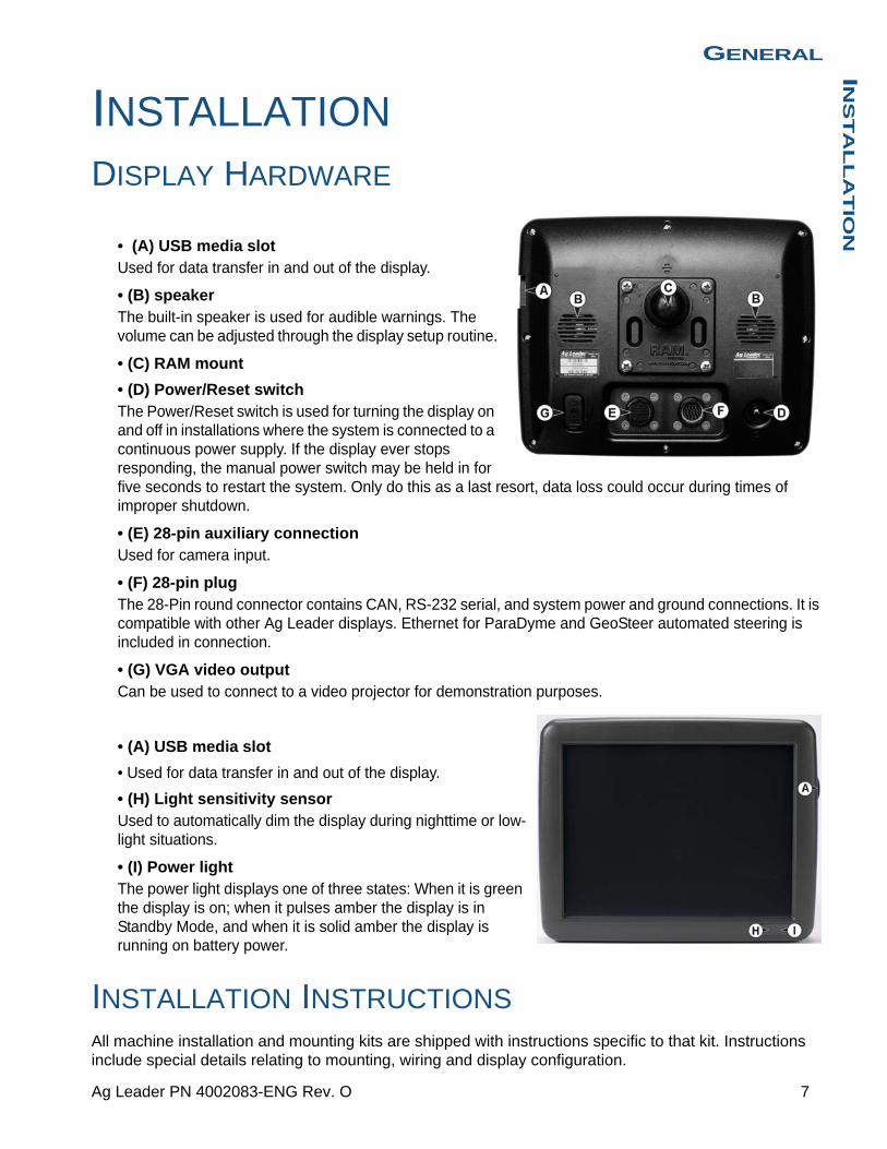
• (A) USB media slotUsed for data transfer in and out of the display.
• (B) speakerThe built-in speaker is used for audible warnings. The volume can be adjusted through the display setup routine.
• (C) RAM mount
• (D) Power/Reset switchThe Power/Reset switch is used for turning the display on and off in installations where the system is connected to a continuous power supply. If the display ever stops responding, the manual power switch may be held in for five seconds to restart the system. Only do this as a last resort, data loss could occur during times of improper shutdown.
• (E) 28-pin auxiliary connectionUsed for camera input.
• (F) 28-pin plugThe 28-Pin round connector contains CAN, RS-232 serial, and system power and ground connections. It is compatible with other Ag Leader displays. Ethernet for ParaDyme and GeoSteer automated steering is included in connection.
• (G) VGA video output Can be used to connect to a video projector for demonstration purposes.
• (A) USB media slot
• Used for data transfer in and out of the display.
• (H) Light sensitivity sensorUsed to automatically dim the display during nighttime or low-light situations.
• (I) Power lightThe power light displays one of three states: When it is green the display is on; when it pulses amber the display is in Standby Mode, and when it is solid amber the display is running on battery power.
INSTALLATION INSTRUCTIONSAll machine installation and mounting kits are shipped with instructions specific to that kit. Instructions include special details relating to mounting, wiring and display configuration.
7 Ag Leader PN 4002083-ENG Rev. O

Mount the display to a secure support inside the vehicle cab. The following must be considered when choosing a mounting location:
• The display must be readily accessible to the machine operator.
• The display must not obstruct the machine operator's normal driving view.
• The display must not interfere with or limit access to any of the existing machine controls.
• The CAN system cabling be routed and secured without interfering with existing machine controls.
WARNING: If drilling holes is required during the mounting process, care must be taken to insure that damage is not done to existing vehicle wiring, mechanical, or cab structure. Refer to vehicle manufacturer documentation for specific details on your equipment. Follow all OEM instructions, cautions, and warnings
when working around equipment.
• (A) RAM Base
• (B) RAM Arm
• (C) Base
8 Firmware Version 6.3

GENERALIN
ST
AL
LA
TIO
N
FUSE INSTALLATION AND REPLACEMENT
Fuse Type: Blade Style (ATO/ATC)
Rating:
Fuse Holder (orange wire) 5A, 250 VAC
Fuse Holder (pink wire) 15A, 250 VAC
CAUTION: The fuse is to be placed in the fuse holder in-line with the battery power cable and used with display only.
SCREEN ICON CONVENTIONSThe following control buttons are made available for entering names and calibration values into the system.
9 Ag Leader PN 4002083-ENG Rev. O
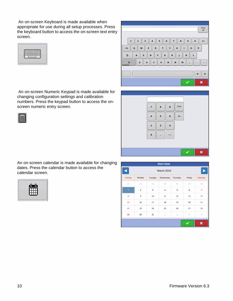
An on-screen Keyboard is made available when appropriate for use during all setup processes. Press the keyboard button to access the on-screen text entry screen.
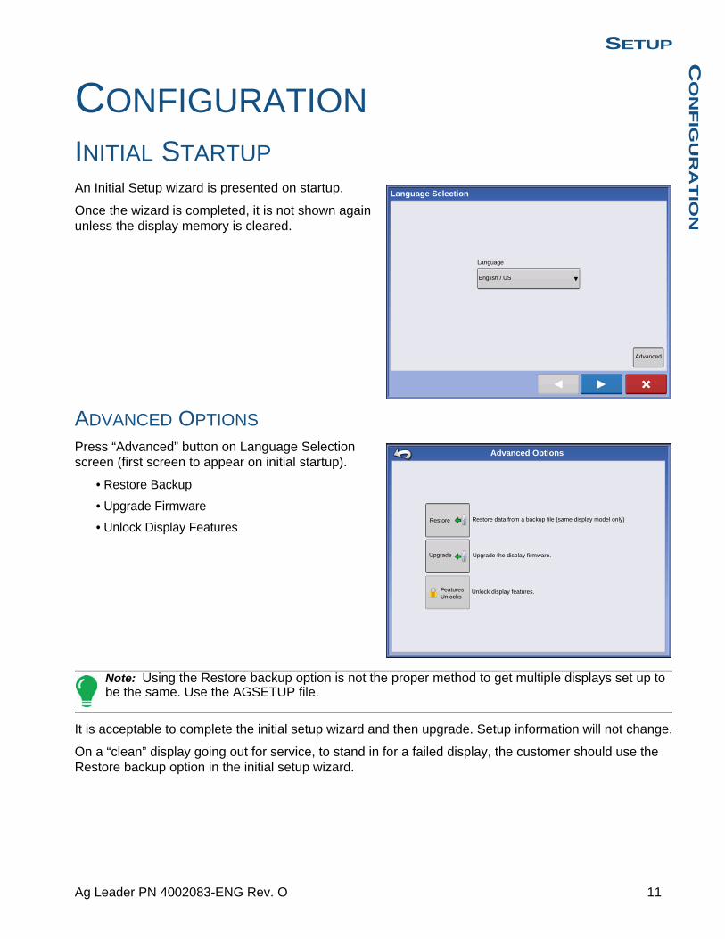
An on-screen Numeric Keypad is made available for changing configuration settings and calibration numbers. Press the keypad button to access the on-screen numeric entry screen.
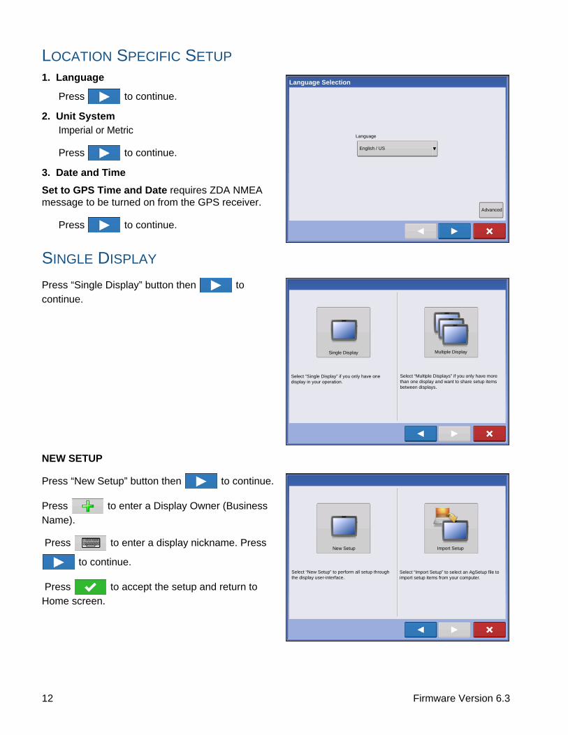
An on-screen calendar is made available for changing dates. Press the calendar button to access the calendar screen.
Symbols
Clear All
Clear
Start Date
March 2015
Sunday Monday Tuesday Wednesday Thursday Friday Saturday
10 Firmware Version 6.3
SETUPC
ON
FIG
UR
AT
ION
SETUP
SETUP
CONFIGURATION
INITIAL STARTUPAn Initial Setup wizard is presented on startup.
Once the wizard is completed, it is not shown again unless the display memory is cleared.
ADVANCED OPTIONS
Press “Advanced” button on Language Selection screen (first screen to appear on initial startup).
• Restore Backup
• Upgrade Firmware
• Unlock Display Features
Note: Using the Restore backup option is not the proper method to get multiple displays set up to be the same. Use the AGSETUP file.
It is acceptable to complete the initial setup wizard and then upgrade. Setup information will not change.
On a “clean” display going out for service, to stand in for a failed display, the customer should use the Restore backup option in the initial setup wizard.
Language Selection
Language
English / US
Advanced
Advanced Options
Restore
Upgrade
Restore data from a backup file (same display model only)
Upgrade the display firmware.
Unlock display features.Features Unlocks
11 Ag Leader PN 4002083-ENG Rev. O
LOCATION SPECIFIC SETUP
1. Language
Press to continue.
2. Unit SystemImperial or Metric
Press to continue.
3. Date and Time
Set to GPS Time and Date requires ZDA NMEA message to be turned on from the GPS receiver.
Press to continue.
SINGLE DISPLAY
Press “Single Display” button then to
continue.
NEW SETUP
Press “New Setup” button then to continue.
Press to enter a Display Owner (Business
Name).
Press to enter a display nickname. Press
to continue.
Press to accept the setup and return to
Home screen.
Language Selection
Language
English / US
Advanced
Single Display Multiple Display
Select “Single Display” if you only have one display in your operation.
Select “Multiple Displays” if you only have more than one display and want to share setup items between displays.
New Setup Import Setup
Select “New Setup” to perform all setup through the display user-interface.
Select “Import Setup” to select an AgSetup file to import setup items from your computer.
12 Firmware Version 6.3
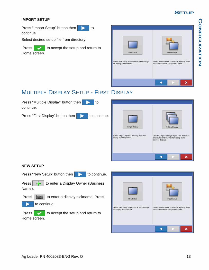
SETUPC
ON
FIG
UR
AT
ION
IMPORT SETUP
Press “Import Setup” button then to
continue.
Select desired setup file from directory.
Press to accept the setup and return to
Home screen.
MULTIPLE DISPLAY SETUP - FIRST DISPLAY
Press “Multiple Display” button then to
continue.
Press “First Display” button then to continue.
NEW SETUP
Press “New Setup” button then to continue.
Press to enter a Display Owner (Business Name).
Press to enter a display nickname. Press
to continue.
Press to accept the setup and return to Home screen.
New Setup Import Setup
Select “New Setup” to perform all setup through the display user-interface.
Select “Import Setup” to select an AgSetup file to import setup items from your computer.
Single Display Multiple Display
Select “Single Display” if you only have one display in your operation.
Select “Multiple Displays” if you have more than one display and want to share setup items between displays.
New Setup Import Setup
Select “New Setup” to perform all setup through the display user-interface.
Select “Import Setup” to select an AgSetup file to import setup items from your computer.
13 Ag Leader PN 4002083-ENG Rev. O
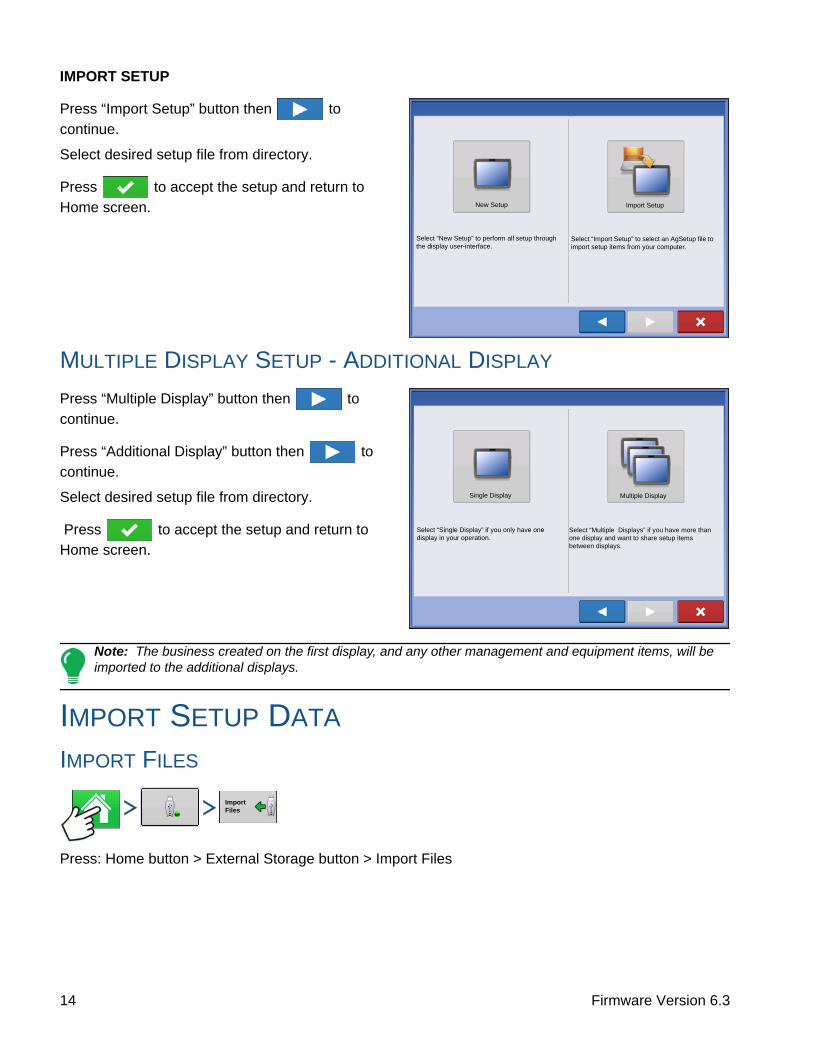
IMPORT SETUP
Press “Import Setup” button then to
continue.
Select desired setup file from directory.
Press to accept the setup and return to
Home screen.
MULTIPLE DISPLAY SETUP - ADDITIONAL DISPLAY
Press “Multiple Display” button then to
continue.
Press “Additional Display” button then to
continue.
Select desired setup file from directory.
Press to accept the setup and return to Home screen.
Note: The business created on the first display, and any other management and equipment items, will be imported to the additional displays.
IMPORT SETUP DATA
IMPORT FILES
Press: Home button > External Storage button > Import Files
New Setup Import Setup
Select “New Setup” to perform all setup through the display user-interface.
Select “Import Setup” to select an AgSetup file to import setup items from your computer.
Single Display Multiple Display
Select “Single Display” if you only have one display in your operation.
Select “Multiple Displays” if you have more than one display and want to share setup items between displays.
Import Files
14 Firmware Version 6.3

SETUPC
ON
FIG
UR
AT
ION
Use the scroll bar to find the file you wish to import.
When a setup file is created it is saved in a folder titled with the displays serial number _nickname. The file will include a date and have the .agsetup suffix.
Select the desired setup file from directory and press
.
Highlight item with conflict
Press
Conflicts can be resolved by:
• Rename Import
• Rename Existing
• Merge- Product Mixes and Configurations can not be
merged. The Merge button will be grayed out and not selectable for these items.
Once all conflicts have been resolved. press .
HOME SCREEN
Press: Home button
Most of the functionality of the display is not available until the basic setup process is completed.
(A) Status bar
(B) Setup button
(C) Task bar
You must complete these initial configuration steps for the Run Time Environment to be active:
1. Grower, Farm, and Field management
For more information, See “Management button” on page 30.
No Preview
2009120009-2-634
Demo Waterway
2009120009-2-634
2009120009-2-634
North Field
Waterloo Farm
Davenport Farm
Ashton Farm
Name Size
File Selection
Resolve
Conflict Resolution
Item to Import
Name:Modification Time:
Creation Time:
Corn03/05/2012 14:24
03/05/2012 14:24
Existing Item
Name:
Modification Time:
Creation Time:01/09/2012 08:35
01/09/2012 08:35
Rename the item being imported.
Rename the existing Item.
Merge the imported and existing items together.
Rename Imported
Rename Existing
Corn
Merge
Select Event
12:25:14 PM
5/10/2012
Guidance
15 Ag Leader PN 4002083-ENG Rev. O

2. Equipment Operating ConfigurationYou can access Configuration Setup by pressing the Setup (wrench) button (B) at the upper right-hand portion of the Home screen. For more information, see “Configuration button” on page 21.
3. Product setupFor more information, see “Product tab” on page 22, as well as the additional configuration information described in each Operations chapter.
4. Select EventFor more information, “Setup Event” on page 45.
SETUP BUTTONS
Press: Home button > Setup (wrench) button
The Setup buttons are used to toggle between screens that adjust settings for Configuration, Management, GPS and display.
• Configuration buttonPress to adjust the configuration settings particular to your vehicle and equipment; as well as enter and edit product information. For more information,
see “Product tab” on page 22, as well as “Configuration Setup Screen” on page 44.
• Management buttonPress to access and edit Grower, Farm, Field and Operator information. For more information, see “Management button” on page 30.
• GPS buttonPress to adjust Guidance settings, GPS settings, and lightbar settings (if applicable). For more information, see “Guidance” on page 125.
• Display buttonPress to adjust settings for Time and Date, brightness and volume settings, operating units, language; enable video; view features; and also create and
restore backups.
DISPLAY BUTTON
Press: Home button > Setup (wrench) button > Display button
The Display screen contains the following tabs:
16 Firmware Version 6.3
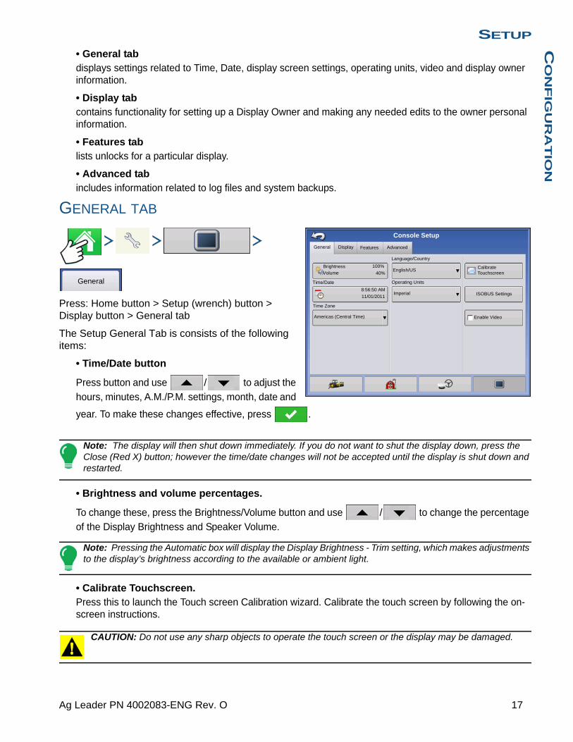
SETUPC
ON
FIG
UR
AT
ION
• General tabdisplays settings related to Time, Date, display screen settings, operating units, video and display owner information.
• Display tabcontains functionality for setting up a Display Owner and making any needed edits to the owner personal information.
• Features tablists unlocks for a particular display.
• Advanced tabincludes information related to log files and system backups.
GENERAL TAB
Press: Home button > Setup (wrench) button > Display button > General tab
The Setup General Tab is consists of the following items:
• Time/Date button
Press button and use / to adjust the
hours, minutes, A.M./P.M. settings, month, date and
year. To make these changes effective, press .
Note: The display will then shut down immediately. If you do not want to shut the display down, press the Close (Red X) button; however the time/date changes will not be accepted until the display is shut down and restarted.
• Brightness and volume percentages.
To change these, press the Brightness/Volume button and use / to change the percentage of the Display Brightness and Speaker Volume.
Note: Pressing the Automatic box will display the Display Brightness - Trim setting, which makes adjustments to the display’s brightness according to the available or ambient light.
• Calibrate Touchscreen.Press this to launch the Touch screen Calibration wizard. Calibrate the touch screen by following the on-screen instructions.
CAUTION: Do not use any sharp objects to operate the touch screen or the display may be damaged.
General Display Features Advanced
Brightness 100%
Volume 40%
Time/Date
8:56:50 AM
11/01/2011
Time Zone
Americas (Central Time)
Language/Country
English/US
Operating Units
Imperial
Enable Video
Console Setup
Calibrate Touchscreen
ISOBUS Settings
General
17 Ag Leader PN 4002083-ENG Rev. O

• Time ZoneUse the drop-down menu to select your time zone.
• Language/Country SelectionUse the drop-down menu to select the language.
• Operating UnitsSelect either Imperial or Metric.
• Enable VideoEnables input from up to four video cameras.
• ISOBUS SettingsEnables Virtual Terminal and Task Controller
DISPLAY TAB
Press: Home button > Setup (wrench) button > Display button > Display tab
The Display tab contains functionality for setting up a Display Owner and making any needed edits to the owner personal information. The Display Owner information is used in the product application report feature of application rate control.
• Nickname
• Serial Number
• Product Type
• Owner
• Phone
• Address
• Image
• Change Owner
• Edit Information
Display Features Advanced
Phone:
Console Setup
General
Edit Information
Change Owner
Nickname: geoSerial Number: 2009120056
Product Type: AL VERSA
Owner: George Eilers
Phone:Email:
Address:
Image:
This Display
geoDisplay
18 Firmware Version 6.3

SETUPC
ON
FIG
UR
AT
ION
FEATURES TAB
Press: Home button > Setup (wrench) button > Display button > Features tab
Unlocking Features
The Features Tab is where you can enter unlock codes. Unlock codes are unique to the serial number of each display and the feature registration number. You must supply these numbers to your dealer when
purchasing any unlock codes. Press to enter
the unlock code and press to enable the feature.
Note: Once a feature is unlocked, that feature remains with that display and cannot be transferred to another.
ADVANCED TAB
Press: Home button > Setup (wrench) button > Display button > Advanced tab
The Advanced Tab allows you to specify settings for copying log files; specify Key Switch Standby settings; view and manually upgrade module firmware; and create and restore backup files.
CAUTION: The Export Diagnostic Files, Advanced Parameters, Copy Debug Files, Clear Debug Files and Service Mode functionality on the Advanced Tab is reserved for use by the manufacturer. DO NOT change any of these settings without specific instruction from the manufacturer.
Features
Features Advanced
Console Setup
General
Feature
Automatic Swath Control
Multiple Product
Norac UC5 Interface
Fan Frame - Feed Gate Control
Status
Enabled
Enabled
Enabled
Enabled
Feature Description:
Unlock
Enabled
Display
ISOBUS Virtual Terminal
HARDI Sprayer Off
Advanced
Display Features Advanced
Console Setup
General
Log FilesKey Switch Standby
5
About
Memory Guidance(minutes)
Export by Grower
Export data files on shutdown
Export Diagnostic Files
Restore Backup
Create Backup
Export All Log Files
Advanced Parameters
Copy Debug Files
Clear Debug Files
Clear Internal Memory
Remove Patterns
Memory Test
Service Mode
View Module Firmware
19 Ag Leader PN 4002083-ENG Rev. O
• Key Switch StandbyThis setting allows the display to remain powered up after the vehicle power has been shut down. Instead, the display will switch into standby mode and will appear to be shut off; however the power light will change to an amber color. Pressing the touchscreen while it is in standby mode will immediately turn the screen back on again.
Use / to specify a length of time that you wish the display to remain powered up in standby
mode after the vehicle power has been shut down.
Note: When the time you specified in Key Switch Standby is nearly expired, then the amber-colored power light will flash on and off immediately preceding shutdown. If you wish the display to remain powered up for a longer period of time, touch the display to restart the Key Switch Standby countdown.
• About buttonDisplays product licensing information and copyright information.
• Log FilesThese settings allow you to copy your data in the display.
- Export by Grower Press of export log files by growers.
- Export Data Files. Press to copy all logged data in the display to the USB drive.
- Export Data Files on Shutdown. Checking this checkbox will copy all log files to the USB drive when the display is powering down.
- See “Export Files” on page 74 for more information.
• MemoryAdjusts information stored in the display’s internal memory.
- Create Backup. Press to create a backup file of all configuration settings, products, and Grower-Farm-Field Management data structure on the USB drive. Backup files are stored using the .ibk2 file format.
- Restore Backup. Press to restore a backup file from the external data drive to the internal memory of the display.
- Clear Internal Memory. Press this button to clear the internal memory of the display. The system will present a warning dialog box and ask if you would like to create a backup file prior to clearing the memory.
CAUTION: Once you clear the system’s internal memory, this information is deleted and cannot be restored unless a backup has been made.
• View Module Firmware. Displays the Module Firmware Management screen, which is a list of all firmware modules and firmware versions that are available for the display.
Note: The Module Firmware Management list includes module firmware that you may not be running.
- Import - Imports any firmware stored on the USB drive into the display memory.
- Direct Upgrade - Upgrades an individual module directly from the USB.
- Remove - Removes unwanted module firmware from the Module Firmware Management list.
Note: Pressing the Remove button does not remove firmware from the module itself. It merely removes the upgrade file from the display.
• Remove Patterns. Pressing this button permanently erases all guidance patterns from the display’s memory.
20 Firmware Version 6.3
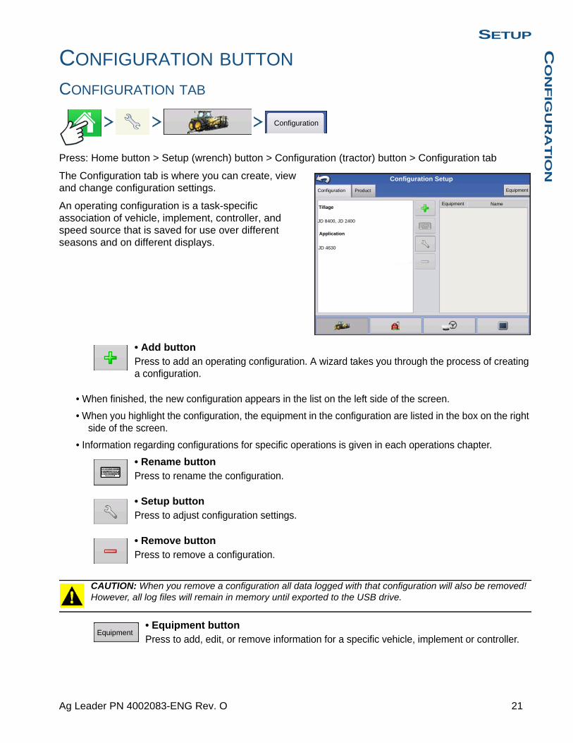
SETUPC
ON
FIG
UR
AT
ION
CONFIGURATION BUTTON
CONFIGURATION TAB
Press: Home button > Setup (wrench) button > Configuration (tractor) button > Configuration tab
The Configuration tab is where you can create, view and change configuration settings.
An operating configuration is a task-specific association of vehicle, implement, controller, and speed source that is saved for use over different seasons and on different displays.
• Add buttonPress to add an operating configuration. A wizard takes you through the process of creating a configuration.
• When finished, the new configuration appears in the list on the left side of the screen.
• When you highlight the configuration, the equipment in the configuration are listed in the box on the right side of the screen.
• Information regarding configurations for specific operations is given in each operations chapter.
• Rename buttonPress to rename the configuration.
• Setup buttonPress to adjust configuration settings.
• Remove buttonPress to remove a configuration.
CAUTION: When you remove a configuration all data logged with that configuration will also be removed! However, all log files will remain in memory until exported to the USB drive.
• Equipment buttonPress to add, edit, or remove information for a specific vehicle, implement or controller.
Configuration
Configuration Setup
ProductConfiguration
Equipment Name
Equipment
Tillage
JD 8400, JD 2400
Application
JD 4630
Equipment
21 Ag Leader PN 4002083-ENG Rev. O
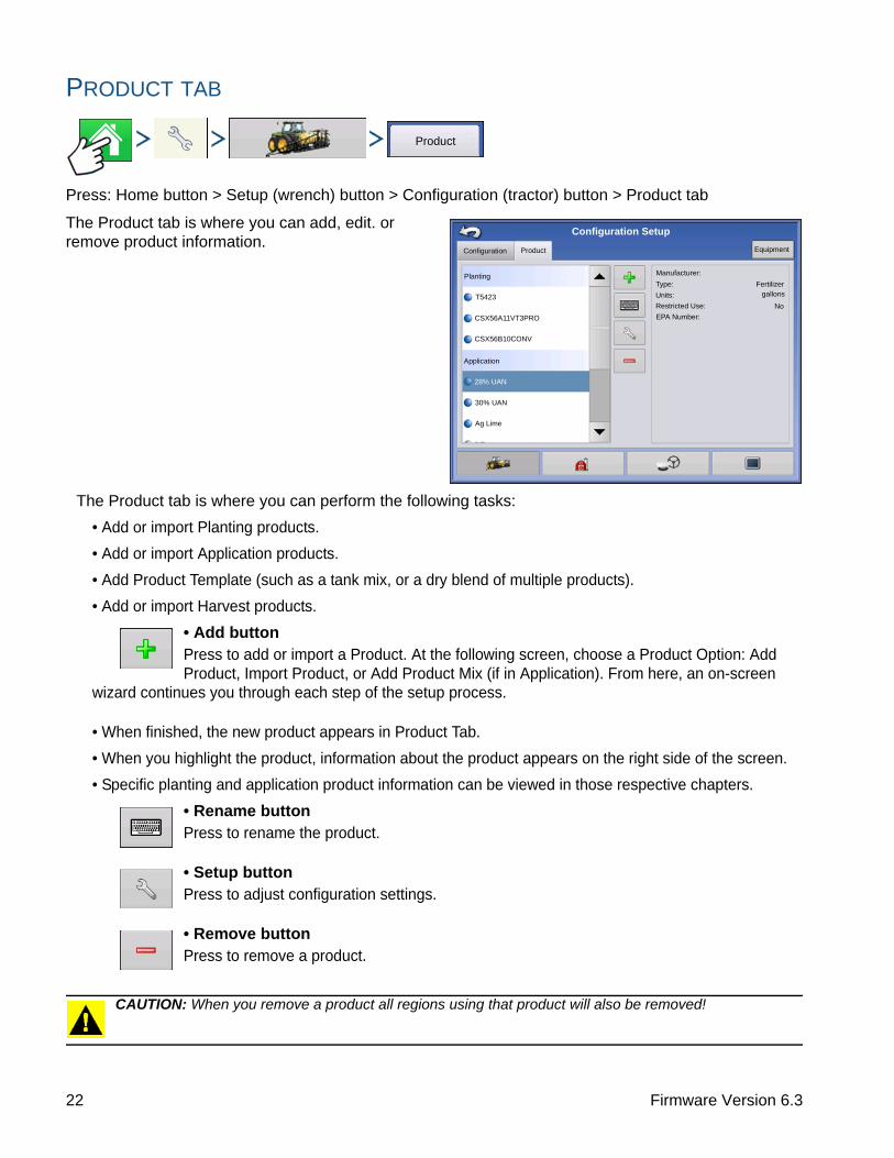
PRODUCT TAB
Press: Home button > Setup (wrench) button > Configuration (tractor) button > Product tab
The Product tab is where you can add, edit. or remove product information.
The Product tab is where you can perform the following tasks:
• Add or import Planting products.
• Add or import Application products.
• Add Product Template (such as a tank mix, or a dry blend of multiple products).
• Add or import Harvest products.
• Add buttonPress to add or import a Product. At the following screen, choose a Product Option: Add Product, Import Product, or Add Product Mix (if in Application). From here, an on-screen
wizard continues you through each step of the setup process.
• When finished, the new product appears in Product Tab.
• When you highlight the product, information about the product appears on the right side of the screen.
• Specific planting and application product information can be viewed in those respective chapters.
• Rename buttonPress to rename the product.
• Setup buttonPress to adjust configuration settings.
• Remove buttonPress to remove a product.
CAUTION: When you remove a product all regions using that product will also be removed!
Product
Configuration
Configuration Setup
Product Equipment
Manufacturer:
Type:
Units:
Restricted Use:
EPA Number:
Fertilizer
No
Planting
Application
T5423
28% UAN
30% UAN
Ag Lime
CSX56A11VT3PRO
CSX56B10CONV
gallons
22 Firmware Version 6.3

SETUPC
ON
FIG
UR
AT
ION
Planting Settings• Edit Info buttonPress to edit the following information for the highlighted product in the Product List.
- Manufacturer
• Edit Legend buttonPress to change the legend settings listed below.
- Average
- Range Spacing
- Color Scheme
- Ranges
- Reset to Default Legend
For more information, see “Legend Settings” on page 52.
Application Settings• Edit Info buttonPress to edit the following information for the highlighted product in the Product List.
- Product Units
- Manufacturer
- EPA Number
- check box for restricted use pesticides
• Edit Legend buttonPress to change the legend settings listed below.
- Average
- Range Spacing
- Color Scheme
- Ranges
- Reset to Default Legend
For more information, see “Legend Settings” on page 52.
Grain Harvest Settings• Crop SettingsPress the Edit button to open the Grain Settings screen where you can adjust the following settings:
- Dry% The percentage of grain moisture used to calculate Dry Bushels- Weight to Volume The Weight to Volume conversion number used to calculate bushels.- Expand bushels for all grains below dry% If the moisture of the harvested crop is below the dry
percentage, the display increases weight to show the weight which would be shown if the crop equaled or exceeded the dry percentage.
• Legend SettingsChoose Yield or Moisture from drop down box.
Press Edit Legend to change the settings listed below.
- Average
- Range Spacing
- Color Scheme
- Ranges
- Reset to Default Legend
23 Ag Leader PN 4002083-ENG Rev. O

For more information, see “Legend Settings” on page 52.
24 Firmware Version 6.3

SETUPM
AN
AG
EM
EN
T S
ET
UP
SETUP
MANAGEMENT SETUPCONFIGURATION SELECTION
Note: Configuration Setup is specific to an operation (Guidance, Tillage, Planting, Application, Harvest). Go to the specific operation section in this manual for information on how to setup a configuration.
1. Press the Configuration button on the home page. Configuration button shows name of current selected configuration. System defaults to guidance configuration.
2. Operating Configuration Selection
Use to select an operating configuration from the drop-down menu.
3. Press to finish Configuration Selection process.
All Modules Detected
Configuration can be loaded and is detecting all modules setup in the configuration.
Display is detecting the module.
Modules Missing
Configuration can not be loaded.
Display is not detecting module.
Guidance
CIH Magnum 180, White 8816
Equipment Name
Vehicle CIH Magnum 180
Implement White 8816
Device Row Shutoff
Auxiliary Input Module
Row Clutch Control Module
Device Seed Monitor
Seed Tube Monitor Module
Operating Configuration
CIH Magnum 340, JD1770
Auxiliary Input Module: Not found
Planter Hydraulic Rate Control Module: Not found
Device Row Shutoff
Auxiliary Input Module: Not found
Row Clutch Control Module: Not found
Seed MonitorDevice
Seed Tube Monitor Module: Not found
Equipment Name
Operating Configuration
25 Ag Leader PN 4002083-ENG Rev. O
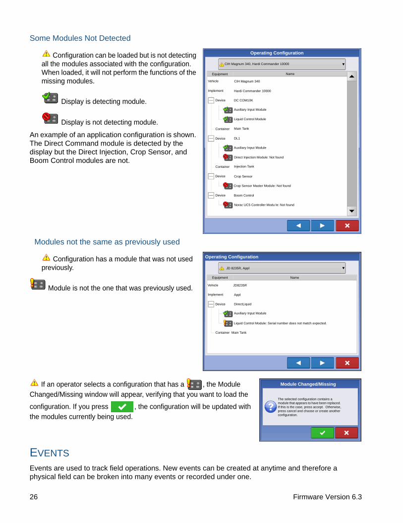
Some Modules Not Detected
Configuration can be loaded but is not detecting all the modules associated with the configuration. When loaded, it will not perform the functions of the missing modules.
Display is detecting module.
Display is not detecting module.
An example of an application configuration is shown. The Direct Command module is detected by the display but the Direct Injection, Crop Sensor, and Boom Control modules are not.
Modules not the same as previously used
Configuration has a module that was not used previously.
Module is not the one that was previously used.
If an operator selects a configuration that has a , the Module Changed/Missing window will appear, verifying that you want to load the
configuration. If you press , the configuration will be updated with the modules currently being used.
EVENTS
Events are used to track field operations. New events can be created at anytime and therefore a physical field can be broken into many events or recorded under one.
CIH Magnum 340, Hardi Commander 10000
CIH Magnum 340
Hardi Commander 10000
DC COM10K
Auxiliary Input Module
Liquid Control Module
NameEquipment
Container Main Tank
Device DL1
Auxiliary Input Module
Direct Injection Module: Not found
Container Injection Tank
Device Crop Sensor
Crop Sensor Master Module: Not found
Device Boom Control
Norac UC5 Controller Modu le: Not found
Vehicle
Implement
Device
Operating Configuration
JD 8235R, Appl
Equipment
Vehicle JD8235R
Implement
Name
Appl
Device DirectLiquid
Auxiliary Input Module
Liquid Control Module: Serial number does not match expected.
Container Main Tank
Operating Configuration
The selected configuration contains a module that appears to have been replaced. If this is the case, press accept. Otherwise, press cancel and choose or create another configuration.
Module Changed/Missing
26 Firmware Version 6.3
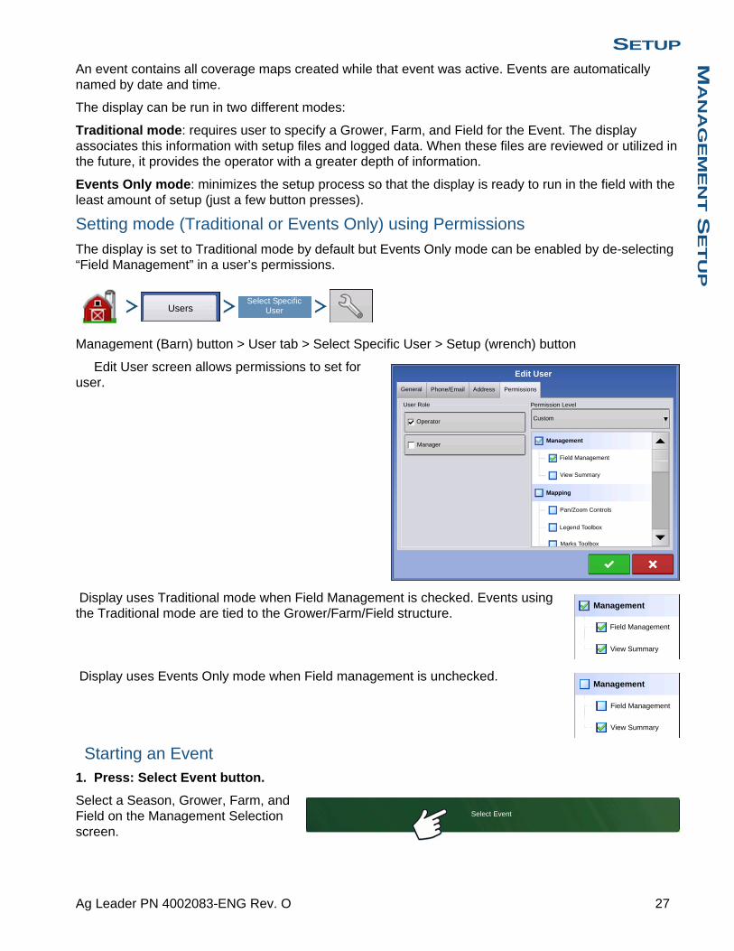
SETUPM
AN
AG
EM
EN
T S
ET
UP
An event contains all coverage maps created while that event was active. Events are automatically named by date and time.
The display can be run in two different modes:
Traditional mode: requires user to specify a Grower, Farm, and Field for the Event. The display associates this information with setup files and logged data. When these files are reviewed or utilized in the future, it provides the operator with a greater depth of information.
Events Only mode: minimizes the setup process so that the display is ready to run in the field with the least amount of setup (just a few button presses).
Setting mode (Traditional or Events Only) using Permissions
The display is set to Traditional mode by default but Events Only mode can be enabled by de-selecting “Field Management” in a user’s permissions.
Management (Barn) button > User tab > Select Specific User > Setup (wrench) button
Edit User screen allows permissions to set for user.
Display uses Traditional mode when Field Management is checked. Events using the Traditional mode are tied to the Grower/Farm/Field structure.
Display uses Events Only mode when Field management is unchecked.
Starting an Event1. Press: Select Event button.
Select a Season, Grower, Farm, and Field on the Management Selection screen.
UsersSelect Specific
User
Edit User
General Phone/Email
User Role
Operator
Manager
Address
Permission Level
Custom
Management
Field Management
View Summary
Mapping
Pan/Zoom Controls
Legend Toolbox
Marks Toolbox
Permissions
Management
Field Management
View Summary
Management
Field Management
View Summary
Select Event
27 Ag Leader PN 4002083-ENG Rev. O

Note: This screen does not appear when operating in Events Only mode.
Enable Management button
is checked by default and requires a Grower, Farm, and Field to be entered before proceeding.
To create a Grower, Farm, and Field press the
button on current screen and press
again next screen. Then type in name and press
twice.
Grower, Farm, and Field can also be created in
Management setup . See “Grower/Farm/Field
tab” on page 30 to set up information using Management setup.
Un-checking Enable Management button will allow operator to continue to next screen without entering additional information on this screen (similar to Events Only mode).
Next screen will vary depending on configuration.
For Example:
The screen shown to the left will appear for Guidance configurations.
For Application configurations the screen will involve product selection.
For Seeding configurations the screen will involve seed selection.
Make selections and press to continue.
Map screen will appear and user can begin operation.
Managing Events
Edit Event Name, Suspend Event, and Clear Map Bounds
Press Setup button (wrench) on Event bar.
2014 Crop
Growing Season
Grower
George Eilers
Farm
Sheldon
Field
Management Selection
Enable Management
Orab
Enable Management
Enable Management
Pattern Options
New Guidance Pattern
Change Pattern
Implement Width:
Guidance Width
30.0000
30.0000
Enable Tramlines
Straight
Event: 2014-01-09_14:40:42Grower: George Eilers
Farm: Sheldon Field: Orab
28 Firmware Version 6.3

SETUPM
AN
AG
EM
EN
T S
ET
UP
The Event Options screen allows operator to change the Event name, Suspend Event, and to Clear Map bounds.
Select a Previous Event
Press event name on Event bar.
Note: This screen does not appear when operating in Events Only mode.
Management Selection screen appears.
Press to accept.
The Field Operation Wizard: Event Selection screen allows the operator to pick a previously created event.
Press to accept.
Event Options
Suspend Event
Event Name
014-01-10_08:3:31
Clear Map Bounds
Event: 2014-01-09_14:40:42Grower: George Eilers
Farm: Sheldon Field: Orab
2014 Crop
Growing Season
Grower
George Eilers
Farm
Sheldon
Field
Management Selection
Enable Management
Orab
Event Selection
New Event
2014-01-12_16:01:17
2014-01-12_15:54:14
Corn
29 Ag Leader PN 4002083-ENG Rev. O

MANAGEMENT BUTTON
Press: Home button > Setup (wrench) button > Management (Barn) button
From this screen the operator can access Grower/Farm/Field, Season, User, and Businesses tabs.
GROWER/FARM/FIELD TAB
Press: Home button > Setup (wrench) button > Management (Barn) button > Grower/Farm/Field tab
Grower
The Grower refers to the business or person that the system is in operation for. Contact information can also be entered for each Grower. The Grower information will be passed into mapping software for automatic Grower setup within desktop software.
• Add buttonPress to add a Grower.
• Rename buttonEdit an existing name of a Grower by highlighting that name and pressing button.
• Setup buttonPress to enter information for the Grower’s Name, Tax ID and Memo.
• Remove buttonPress to remove a Grower.
Note: Personal Information entered at this screen can be added or edited at any time.
Grower/Farm/Field
30 Firmware Version 6.3
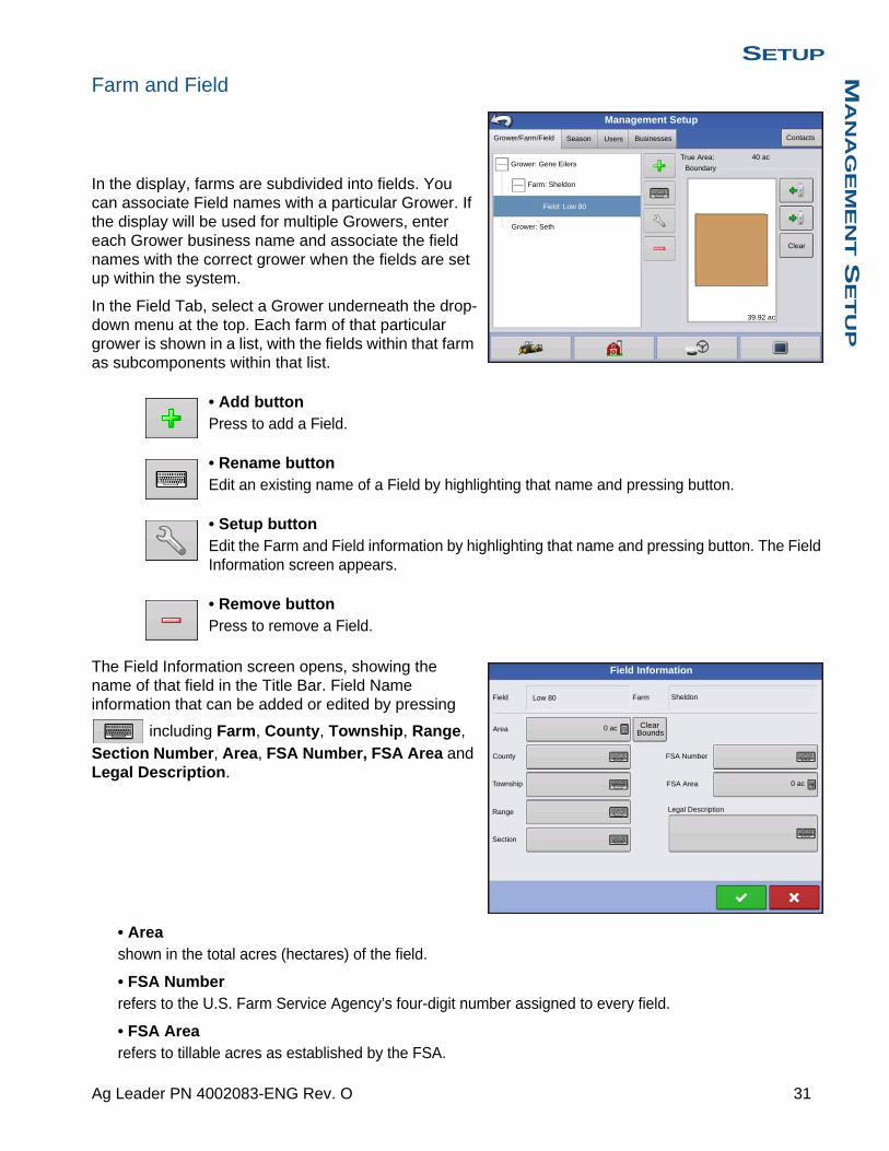
SETUPM
AN
AG
EM
EN
T S
ET
UP
Farm and Field
In the display, farms are subdivided into fields. You can associate Field names with a particular Grower. If the display will be used for multiple Growers, enter each Grower business name and associate the field names with the correct grower when the fields are set up within the system.
In the Field Tab, select a Grower underneath the drop-down menu at the top. Each farm of that particular grower is shown in a list, with the fields within that farm as subcomponents within that list.
• Add buttonPress to add a Field.
• Rename buttonEdit an existing name of a Field by highlighting that name and pressing button.
• Setup buttonEdit the Farm and Field information by highlighting that name and pressing button. The Field Information screen appears.
• Remove buttonPress to remove a Field.
The Field Information screen opens, showing the name of that field in the Title Bar. Field Name information that can be added or edited by pressing
including Farm, County, Township, Range,
Section Number, Area, FSA Number, FSA Area and Legal Description.
• Areashown in the total acres (hectares) of the field.
• FSA Numberrefers to the U.S. Farm Service Agency’s four-digit number assigned to every field.
• FSA Arearefers to tillable acres as established by the FSA.
Grower/Farm/Field Season Users Contacts
Grower: Gene Eilers
Farm: Sheldon
Grower: Seth
Field: Low 80
True Area:
Boundary
Management Setup
Clear
40 ac
39.92 ac
Businesses
Low 80 SheldonField
Area
County
Township
Range
Section
FSA Number
FSA Area
Legal Description
Farm
ClearBounds
Field Information
0 ac
0 ac
31 Ag Leader PN 4002083-ENG Rev. O

• Clear Bounds buttonPress to center the map on the current GPS position.
Note: The Clear Bounds feature is particularly useful if you have flyer points or have logged a point outside the mappable range of your current location.
Importing and Exporting Field Boundaries
Boundaries can be created with the display or imported from desktop GIS software. Any boundary files present in the display can also be exported for use in desktop mapping software.
Note: For more information on creating boundaries, see “Create Boundary” on page 55.
• USB Import buttonTo import a boundary from the USB drive, first go to the Setup Field tab, highlight the correct field in the Farm/Field list and press the USB Import button.
The File Selection screen appears. Highlight the desired file to import.
Operator can import/export all fields and boundaries at once with an .AGSETUP file. For more information on .AGSETUP files see See “.AGSETUP” on page 355.
Press to complete the import process.
• USB Export buttonTo export a boundary to the USB drive, highlight the correct field in the Farm/Field list and press the USB Export button. At the File Selection screen, highlight the desired field to export.
A screen will appear telling you that the boundary was exported successfully. Press return to the field setup screen.
Grower/Farm/Field Season Users Contacts
Grower: Gene Eilers
Farm: Sheldon
Grower: Seth
Field: Low 80
True Area:
Boundary
Management Setup
Clear
40 ac
39.92 ac
Businesses
File Selection
Name
Boundaries
New Folder 1
Field_1.iby
Field_2.iby
Field_3.iby
Field_4.iby
irx_multi_product
irx_single_product
Field:Farm:Grower:
DemoAllegon County
Michigan Test Fields
91.51 ac
32 Firmware Version 6.3

SETUPM
AN
AG
EM
EN
T S
ET
UP
SEASON TAB
Press: Home button > Setup (wrench) button > Management (Barn) button > Season tab
A season is defined as the calendar year that the crop will be harvested. A season has a start and an end date. Creating a season and setting it to active is required prior to the system logging any data.
The seasons are displayed in lists, with the Active season displayed in bold face type. All new data is logged to the active season; therefore a season must be set as Active before you can log any new data to it.
• Add buttonPress to add a Season.
• Edit buttonEdit an existing name of a Season by highlighting that name and pressing button.
• Set Active buttonPress to set the season selected in the Summary list box to the active season.
• Season Reminder buttonPress to set the date that the system will prompt the operator to create a new season.
• Remove buttonPress to remove a season.
USERS TAB
Press: Home button > Setup (wrench) button > Management (Barn) button > User tab
Season
Users
Grower/Farm/Field Season Users
Eilers, George
Eilers, Joan
Schmidt, Jack
Oakes, Bill
Management Setup
Businesses
VanBurkum, Doug
33 Ag Leader PN 4002083-ENG Rev. O
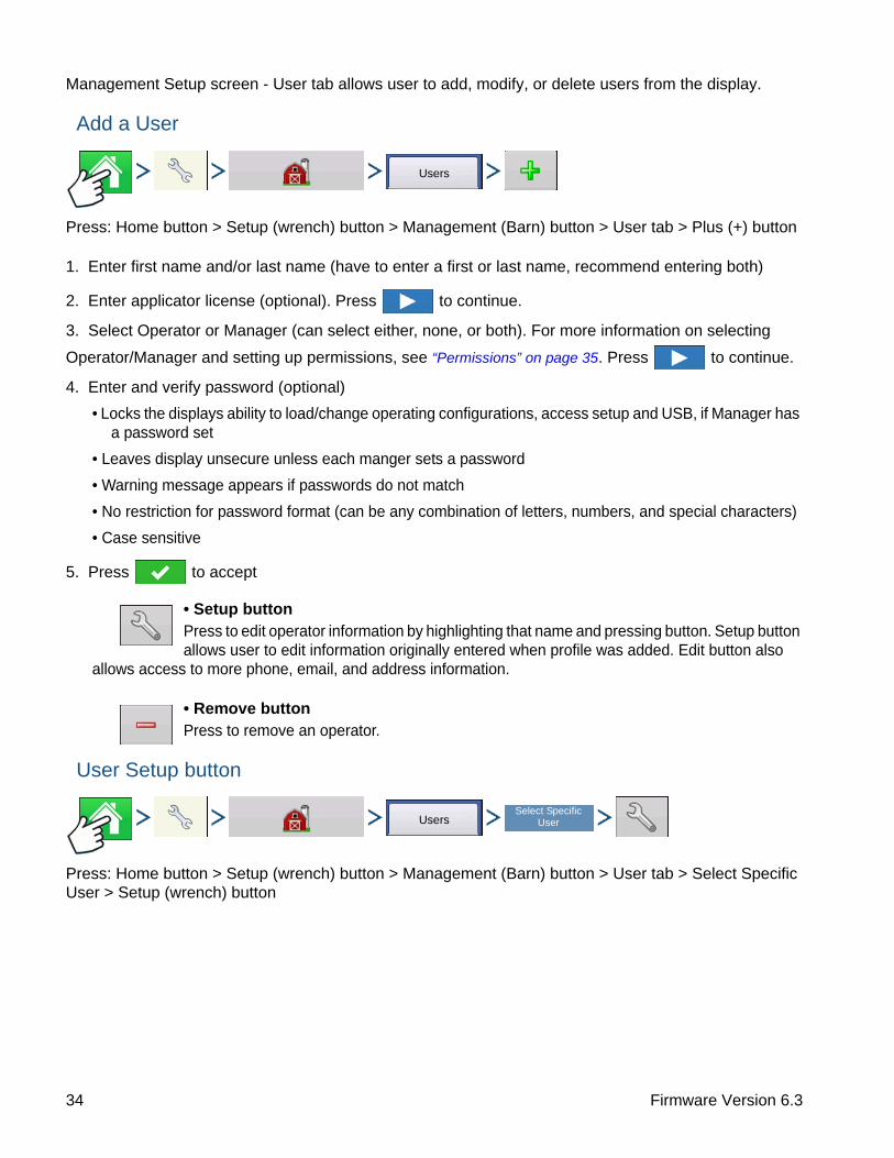
Management Setup screen - User tab allows user to add, modify, or delete users from the display.
Add a User
Press: Home button > Setup (wrench) button > Management (Barn) button > User tab > Plus (+) button
1. Enter first name and/or last name (have to enter a first or last name, recommend entering both)
2. Enter applicator license (optional). Press to continue.
3. Select Operator or Manager (can select either, none, or both). For more information on selecting
Operator/Manager and setting up permissions, see “Permissions” on page 35. Press to continue.
4. Enter and verify password (optional)
• Locks the displays ability to load/change operating configurations, access setup and USB, if Manager has a password set
• Leaves display unsecure unless each manger sets a password
• Warning message appears if passwords do not match
• No restriction for password format (can be any combination of letters, numbers, and special characters)
• Case sensitive
5. Press to accept
• Setup buttonPress to edit operator information by highlighting that name and pressing button. Setup button allows user to edit information originally entered when profile was added. Edit button also
allows access to more phone, email, and address information.
• Remove buttonPress to remove an operator.
User Setup button
Press: Home button > Setup (wrench) button > Management (Barn) button > User tab > Select Specific User > Setup (wrench) button
Users
UsersSelect Specific
User
34 Firmware Version 6.3
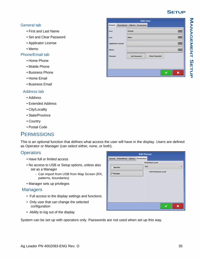
SETUPM
AN
AG
EM
EN
T S
ET
UP
General tab
• First and Last Name
• Set and Clear Password
• Applicator License
• Memo
Phone/Email tab
• Home Phone
• Mobile Phone
• Business Phone
• Home Email
• Business Email
Address tab
• Address
• Extended Address
• City/Locality
• State/Province
• Country
• Postal Code
PERMISSIONS
This is an optional function that defines what access the user will have in the display. Users are defined as Operator or Manager (can select either, none, or both).
Operators• Have full or limited access
• No access to USB or Setup options, unless also set as a Manager
- Can import from USB from Map Screen (RX, patterns, boundaries)
• Manager sets up privileges
Managers• Full access to the display settings and functions
• Only user that can change the selected configuration
• Ability to log out of the display
System can be set up with operators only. Passwords are not used when set up this way.
General Phone/Email Address
George
Eilers
Passwor
First
Edit User
Permissions
Applicator License
Last
Memo
Set Password Clear Password
General Phone/Email Address
Operator
ManagerFull Permission Level
Edit Person
Permissions
Full
Permission Level
35 Ag Leader PN 4002083-ENG Rev. O

PERMISSION LEVEL FOR OPERATORS
Full Permission
Provides full access to features and functionality on the map and home screen. A user, set only as an Operator, cannot select a different configuration and cannot access USB or Setup, when a manager is setup in the display.
Basic Permission
No access to:
• Summary screen
• Legend Tab on Map screen
• Marks Tab on Map screen
• Boundary Tab on Map screen
Limits Guidance options to:
• Creating & loading Straight AB or SmartPath patterns
• Nudge
• Remark A
• Save or reset guidance line
36 Firmware Version 6.3
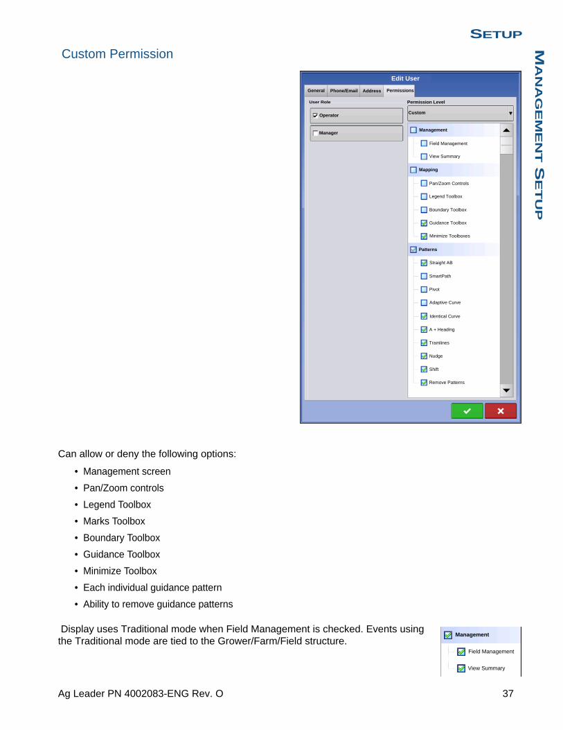
SETUPM
AN
AG
EM
EN
T S
ET
UP
Custom Permission
Can allow or deny the following options:
• Management screen
• Pan/Zoom controls
• Legend Toolbox
• Marks Toolbox
• Boundary Toolbox
• Guidance Toolbox
• Minimize Toolbox
• Each individual guidance pattern
• Ability to remove guidance patterns
Display uses Traditional mode when Field Management is checked. Events using the Traditional mode are tied to the Grower/Farm/Field structure.
General Phone/Email Address
Operator
ManagerManagement
User Role
Edit User
Permissions
Custom
Permission Level
Mapping
Patterns
View Summary
Pan/Zoom Controls
Legend Toolbox
Boundary Toolbox
Guidance Toolbox
Minimize Toolboxes
Straight AB
SmartPath
Pivot
Adaptive Curve
Identical Curve
A + Heading
Tramlines
Nudge
Shift
Remove Patterns
Field Management
Management
Field Management
View Summary
37 Ag Leader PN 4002083-ENG Rev. O
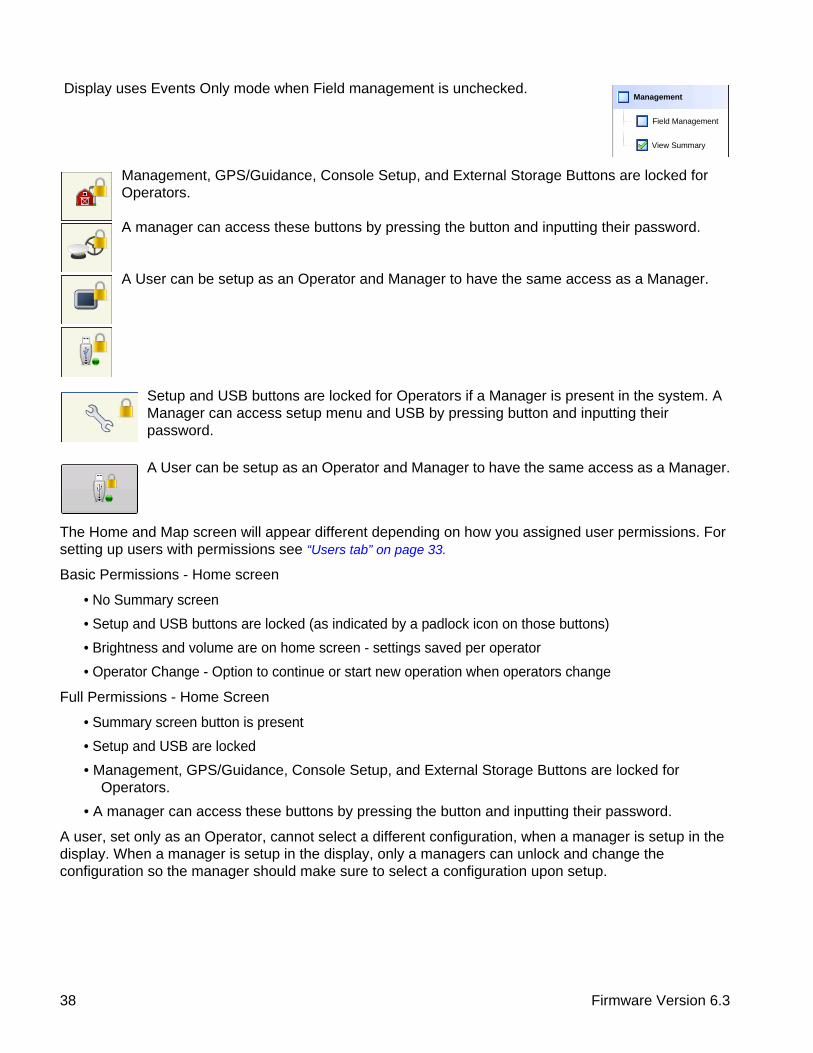
Display uses Events Only mode when Field management is unchecked.
Management, GPS/Guidance, Console Setup, and External Storage Buttons are locked for Operators.
A manager can access these buttons by pressing the button and inputting their password.
A User can be setup as an Operator and Manager to have the same access as a Manager.
Setup and USB buttons are locked for Operators if a Manager is present in the system. A Manager can access setup menu and USB by pressing button and inputting their password.
A User can be setup as an Operator and Manager to have the same access as a Manager.
The Home and Map screen will appear different depending on how you assigned user permissions. For setting up users with permissions see “Users tab” on page 33.
Basic Permissions - Home screen
• No Summary screen
• Setup and USB buttons are locked (as indicated by a padlock icon on those buttons)
• Brightness and volume are on home screen - settings saved per operator
• Operator Change - Option to continue or start new operation when operators change
Full Permissions - Home Screen
• Summary screen button is present
• Setup and USB are locked
• Management, GPS/Guidance, Console Setup, and External Storage Buttons are locked for Operators.
• A manager can access these buttons by pressing the button and inputting their password.
A user, set only as an Operator, cannot select a different configuration, when a manager is setup in the display. When a manager is setup in the display, only a managers can unlock and change the configuration so the manager should make sure to select a configuration upon setup.
Management
Field Management
View Summary
38 Firmware Version 6.3

SETUPM
AN
AG
EM
EN
T S
ET
UP
Map screen appearance of an operator with Basic permission. Only the Guidance toolbox is present.
Operator can
• Create guidance lines- Straight AB
- SmartPath
• Nudge
• Guidance setup
ACCESSING SETUP MENUS
1. Press Setup (wrench) button.
2. Select Manager from drop-down menu. Press .
3. Enter password. Press .
Now have complete access to the setup menus:
• Configurations Settings
• Grower management
• GPS settings
• Display settings
Do not have to be a Manger to create certain objects
• Grower
• Farm
• Field
• Product (can't change units)
ACCESSING USB1. Press USB button
2. Select Manager from drop-down menu. Press .
3. Enter password. Press .
Now have complete access to the USB functions:
• Import/export
• AgSetup files
• Export data
• Upgrade firmware
• Advanced options
0.67 ac 4.5 mph
Guidance
1
New Pattern
Load Pattern
Manage Patterns
39 Ag Leader PN 4002083-ENG Rev. O
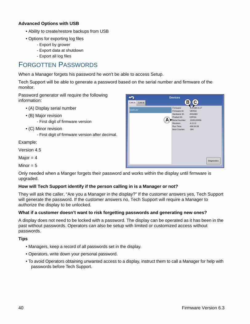
Advanced Options with USB
• Ability to create/restore backups from USB
• Options for exporting log files- Export by grower
- Export data at shutdown
- Export all log files
FORGOTTEN PASSWORDS
When a Manager forgets his password he won't be able to access Setup.
Tech Support will be able to generate a password based on the serial number and firmware of the monitor.
Password generator will require the following information:
• (A) Display serial number
• (B) Major revision- First digit of firmware version
• (C) Minor revision- First digit of firmware version after decimal.
Example:
Version 4.5
Major = 4
Minor = 5
Only needed when a Manger forgets their password and works within the display until firmware is upgraded.
How will Tech Support identify if the person calling in is a Manager or not?
They will ask the caller, “Are you a Manager in the display?” If the customer answers yes, Tech Support will generate the password. If the customer answers no, Tech Support will require a Manager to authorize the display to be unlocked.
What if a customer doesn’t want to risk forgetting passwords and generating new ones?
A display does not need to be locked with a password. The display can be operated as it has been in the past without passwords. Operators can also be setup with limited or customized access without passwords.
Tips
• Managers, keep a record of all passwords set in the display.
• Operators, write down your personal password.
• To avoid Operators obtaining unwanted access to a display, instruct them to call a Manager for help with passwords before Tech Support.
Firmware: 4.0.18/4.0.17
Firmware ID: VERSA
Hardware ID: 4001683
Product ID: VERSA
Serial Number: 2009120056
Revision: 4.3.2.0
Run Time: 436:54:39
Boot Counter: 394
DISPLAY
CAN A CAN B
Devices
Diagnostics
40 Firmware Version 6.3

SETUPM
AN
AG
EM
EN
T S
ET
UP
BUSINESSES TAB
Press: Home button > Setup (wrench) button > Management (Barn) button > Businesses tab
The businesses are displayed in lists, with the Active business displayed in bold face type. All new data is logged to the active business; therefore a business must be set as Active before you can log any new data to it.
• Add buttonPress to add a business
• Edit buttonEdit an existing business by highlighting that name and pressing button.
• Remove buttonPress to remove a business.
Businesses
41 Ag Leader PN 4002083-ENG Rev. O

42 Firmware Version 6.3

SETUPF
IEL
D O
PE
RA
TIO
NS
SETUP
FIELD OPERATIONS
A. Operator Selection, see “Operator Selection” on page 43
B. Edit Operator, see “User Setup button” on page 34
C. Operating Configuration, see “Configuration Selection” on page 25
D. Configuration Setup, see “Configuration Setup Screen” on page 44
E. Event Setup, see “Setup Event” on page 45
F. Event Options, see “Field Operation Options” on page 46
G. Products Tab, shows products, rates and area covered
H. Product Selection, press to change products
I. Rate Control Settings, press to change rates
J. Productivity Tab, shows speed, time, area covered, and distance traveled
K. Region Options, see “Region button” on page 46
L. Field Notes, see “Field Notes button” on page 46
OPERATOR SELECTION
1. Press Select Operator buttonAllows you to select a machine operator from the drop-down list. Machine operator information is logged with all field operations. Operator information may be entered in Management Setup at “Management button” on page 16
0.0 mph0.00 ac
JD 8360R, JD 1770Eilers, George
Event: 2014-01-09_12:39:39
1:36:07 PM
18/01/2012
0 sds/ac
0 sds/ac
0 sds/ac
0.0 sds
0.0 sds
0.0 sds
0.0 ac
0.0 ac
0.0 ac
1222
C1224
C1492
Products Productivity
Grower: George EilersFarm: Sheldon Field: Orab
Region:<1>
Select Operator
43 Ag Leader PN 4002083-ENG Rev. O

2. Choose the operator from drop-down menu.
Note: Checkbox will require a password to be entered upon start up of the display.
Press .
3. Enter password. Press .
The operator will now be selected and permissions active
OPERATOR LOG OUT
Press: Home button > Operator: button > Logout button
Users that are both a Manager and Operator can logout which locks Setup and USB access and an operator must log in before an operation can be performed.
CONFIGURATION SETUP SCREEN
The Configuration Setup screen is where you can make settings adjustments for your equipment, ground speed, GPS, and controllers.
The appearance of this Configuration Setup screen varies, based on your particular configuration. Some DirectCommand and SeedCommand configurations include settings that are mentioned in those individual chapters. Most Configuration Settings screens will include the following buttons.
• Equipment Settings. For more information, see “Equipment Settings” on page 79.
• Speed Input. For more information, see “Speed Input Settings” on page 80.
• AutoSwath. For more information, see “AutoSwath” on page 84.
• GPS Offsets. For more information, see “Vehicle Offsets” on page 85.
• Swath Section Offsets. For more information, see “Swath Section Offsets” on page 86.
• Controller Settings. For more information, see information in the SeedCommand and DirectCommand chapters.
• Calibrate Pressure. Used in DirectCommand Liquid Application configurations.
Operator Selection
Options
Select Operator
Eilers, George
Show Operator Selection on Startup
Note: If the active operator has a password, the operator selection will always be displayed on startup.
Log Out
Guidance
44 Firmware Version 6.3

SETUPF
IEL
D O
PE
RA
TIO
NS
SETUP EVENTYou must have already created the following:
• A Season, Grower, Farm and Field in Setup Management. For more information, see “Management button” on page 30.
• An Operating Configuration at the Setup screen’s Configuration Tab. This Operating Configuration consists of Equipment, Vehicle, Implement, Controller (optional), Container (in Application), and Ground Speed Source.
• A Product (if you are creating an Application or Planting Field Operation) at the Setup Product Tab. For more information, see “Product tab” on page 22.
All of these are referenced by the Field Operation Wizard during the Field Operation setup process.
Press the “Select Event” button and follow the steps in the wizard.
Select Event button opens the Field Operation Wizard where you can enter information relating to your Growing Season, Grower, Farm, Field, Crop Type and Product. For more information, see “Setup Event” on page 45 and also “Field Operation Options” on page 46.
1. Grower, Farm and Field Selection
Enter a Growing Season, Grower, Farm, and Field by pressing to select existing ones from a drop-
down menu, or by pressing to create a new one.
Use to select an operating configuration from the drop-down menu. For more informations on
Configuration Selection see“Configuration Selection” on page 25.
2. Product SelectionA planting or application configuration must include a product. Select product from the drop-down list or
press to create a new one. Press to continue.
• If a configuration is loaded with undetected modules, the Product Selection screen may show some grayed out (unavailable) options. The example to the left shows that the Direct Command module is active but Direct Injection, Crop Sensor, and Boom Control modules are grayed out and not functional.
3. Region Options
Press to edit or change the region name from the system default if desired. At this screen, you can also create a new region or change the controlling product.
Select Event
Product Selection
DC COM10K
DL1
Crop Sensor
Boom Control
Active
Active
Active
Select Product
Active 28% UAN
45 Ag Leader PN 4002083-ENG Rev. O

4. Return to Home screenWhen you complete the steps in the Wizard, you will return to the Home screen.
• For information on Run screen operations, see “Run screens” on page 47.
FIELD FINDER
If you have an existing field boundary, and your current GPS position is within that field boundary, the display will automatically pick the correct Grower, Farm and Field combination when you start a Field Operation.
• Region button
A region is used to subdivide a field into smaller sections. The region in which data is currently being logged is listed on the Region button. A new region can be created at any time as you are performing a field operation.
To change between or add a new region to a field, press the Region button and follow the on-screen instructions.
• Field Notes buttonEdit any of the report items that are listed in Smart Report™. For more information, see “Smart Report™” on page 68.
FIELD OPERATION OPTIONS
During a field operation, you can suspend or close the event by pressing on the wrench at the end of the Grower Farm Field (Select Event) button. This opens the Events Options screen.
Press Setup button (wrench) on Event bar.
The Event Options screen allows operator to change the Event name, Suspend or Close Event, be Prompted to Close the Event, and to Clear Map bounds.
A closed event cannot be re-opened and will not show up in the Event Selection screen. A user can manually close Events or be prompted to close events.
Region:<1>
Event: 2014-01-09_14:40:42Grower: George Eilers
Farm: Sheldon Field: Orab
Event Options
Suspend Event
Event Name
2020-01-10_08:3:31
Clear Map Bounds
Close Event
Prompts to Close Event
46 Firmware Version 6.3

SETUPF
IEL
D O
PE
RA
TIO
NS
RUN SCREENS
• (A) Status Bar
• (B) On-screen Light bar
• (C) Mapping toolbox
• (D) Mapping Function tabs
• (E) Product Control toolbox
• (F) Product tabs
• (G) Function buttons
• (H) Task bar
• (I) Main Screen buttons
• (J) Equipment tab
The appearance of the Map screen varies, depending upon which operation you are performing, and your specific operating configuration.
The task bar displays buttons relating to various functions of the display. These buttons and status indicators include Home, Mapping, Autoswath, Logging, and Auxiliary Input Status. These buttons are shown in front of a green background when you are at that screen; otherwise they are shown in front of a blue background.
Home button - Pressing the Home button takes you to the Home screen.
Map button - Pressing the Map button takes you to the Map screen. Pressing it more than once cycles the Map screen to zoom in and out.
ZOOM DETAILS
ZOOM TO EXTENT
PERSPECTIVE VIEW
Note: The Perspective View is only available when guidance is active.
Video button. Pressing this button takes you to the video screen. Pressing this button repeatedly cycles through the video inputs.
0.67 ac 4.5 mph
sds/ac
40 ft 0 in
Population: 26100 sds/ac Spacing: 8.0 in
0.67 ac
Varieties
Soybeans
Flow:Area:
100%
Planter Drives (rpm)
C1545
10272 sds/min
1
88
104000102000
C1545 1
2
104000
102000
47 Ag Leader PN 4002083-ENG Rev. O

Note: For more information on the Video screen, see “Video” on page 63.
AutoSwath button. Pressing this button turns the AutoSwath feature on and off. When AutoSwath is on, the icon is green; when it is off the icon is white.
AutoSwath - ON
AutoSwath - OFF
Area Logging Status button - This button appears for configurations that do not use rate control, such as Tillage, Harvest, Planting operations that do not use SeedCommand, and Application operations that do not use DirectCommand. Pressing this button turns logging on and off.
ON
OFF
The NORAC Engage button enables boom height control. This button can toggle back and forth between Automatic Mode and Manual Mode.
When you enable Automatic Mode, this button turns green with three lines appearing underneath the triangle. At the same time, the display beeps three times.
When you disable Automatic Mode on any part of the boom and the display switches to Manual Mode, this button turns gray and the display beeps twice. If less than the full boom remains in Manual Mode, the display will continue beeping twice every three seconds.
NORAC Engage - Enabled
NORAC Engage - Disabled
The Engage icon shows that the autosteer system is on, off, or off but ready to engage. The appearance of this icon displays the following:
Engage - ON
Green if the autosteer system is on.
Engage - Ready
Grey if the autosteer system off but ready to engage.
48 Firmware Version 6.3
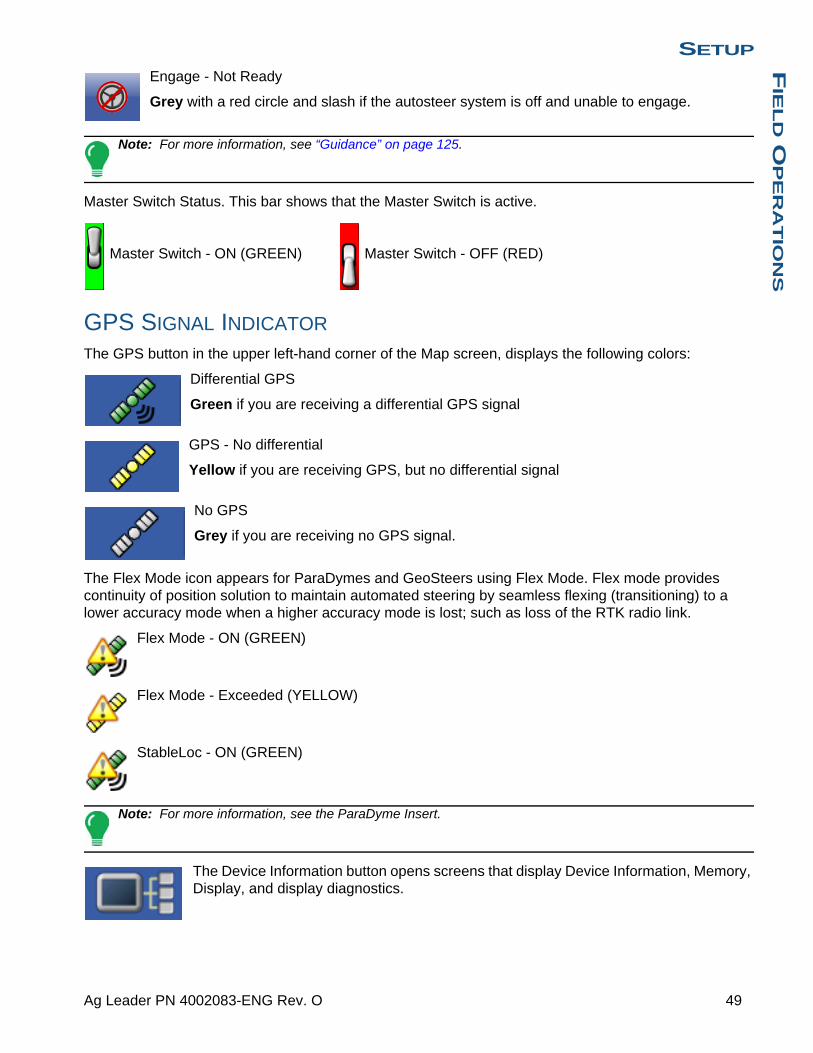
SETUPF
IEL
D O
PE
RA
TIO
NS
Engage - Not Ready
Grey with a red circle and slash if the autosteer system is off and unable to engage.
Note: For more information, see “Guidance” on page 125.
Master Switch Status. This bar shows that the Master Switch is active.
Master Switch - ON (GREEN) Master Switch - OFF (RED)
GPS SIGNAL INDICATOR
The GPS button in the upper left-hand corner of the Map screen, displays the following colors:
Differential GPS
Green if you are receiving a differential GPS signal
GPS - No differential
Yellow if you are receiving GPS, but no differential signal
No GPS
Grey if you are receiving no GPS signal.
The Flex Mode icon appears for ParaDymes and GeoSteers using Flex Mode. Flex mode provides continuity of position solution to maintain automated steering by seamless flexing (transitioning) to a lower accuracy mode when a higher accuracy mode is lost; such as loss of the RTK radio link.
Flex Mode - ON (GREEN)
Flex Mode - Exceeded (YELLOW)
StableLoc - ON (GREEN)
Note: For more information, see the ParaDyme Insert.
The Device Information button opens screens that display Device Information, Memory, Display, and display diagnostics.
49 Ag Leader PN 4002083-ENG Rev. O
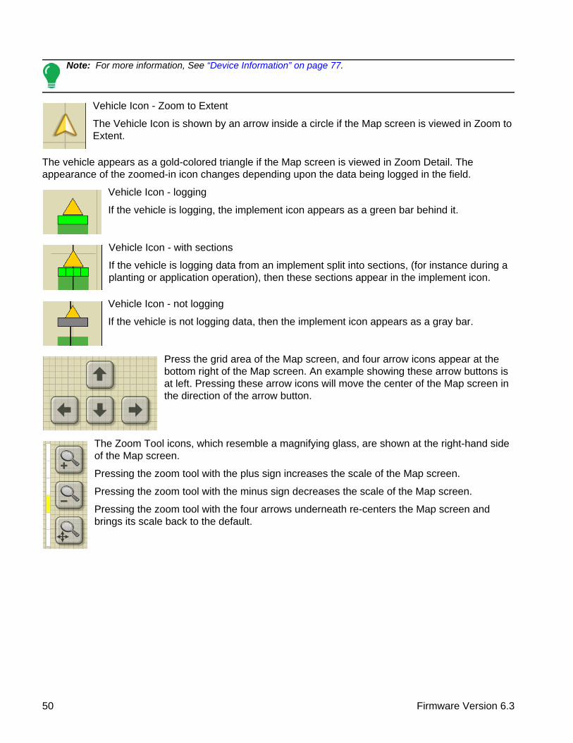
Note: For more information, See “Device Information” on page 77.
Vehicle Icon - Zoom to Extent
The Vehicle Icon is shown by an arrow inside a circle if the Map screen is viewed in Zoom to Extent.
The vehicle appears as a gold-colored triangle if the Map screen is viewed in Zoom Detail. The appearance of the zoomed-in icon changes depending upon the data being logged in the field.
Vehicle Icon - logging
If the vehicle is logging, the implement icon appears as a green bar behind it.
Vehicle Icon - with sections
If the vehicle is logging data from an implement split into sections, (for instance during a planting or application operation), then these sections appear in the implement icon.
Vehicle Icon - not logging
If the vehicle is not logging data, then the implement icon appears as a gray bar.
Press the grid area of the Map screen, and four arrow icons appear at the bottom right of the Map screen. An example showing these arrow buttons is at left. Pressing these arrow icons will move the center of the Map screen in the direction of the arrow button.
The Zoom Tool icons, which resemble a magnifying glass, are shown at the right-hand side of the Map screen.
Pressing the zoom tool with the plus sign increases the scale of the Map screen.
Pressing the zoom tool with the minus sign decreases the scale of the Map screen.
Pressing the zoom tool with the four arrows underneath re-centers the Map screen and brings its scale back to the default.
50 Firmware Version 6.3

SETUPF
IEL
D O
PE
RA
TIO
NS
MAPPING TOOLBOX
At the upper left hand side of the Map screen is the Mapping Toolbox. Press any of the four buttons on the toolbox and it expands. The toolbox consists of the following buttons:
• (A) Map Legend
• (B) Map Markers
• (C) Field
• (D) Guidance
The Map Legend, Map Markers and Field buttons are explained in the rest of this chapter. The Guidance button is described in “Guidance” on page 125.
Map Legend tab
Press the Map Legend button at the top of the Mapping Toolbox, and the Legend appears. User can choose between Rate or Coverage using the drop-down menu.
Map Options
Press the Legend Setup (wrench) button,
and the Map Options screen appears. Here the user can select map options, clear the map, and load a reference map
• Clear MapPermanently removes on-screen map from the active field operation, but the log data will still be exported to the USB drive.
• Load ReferenceLoads a list of maps of previous operations performed in that field. For each operation, you can view As-Applied or Coverage attributes (and Varieties if you are performing a Planting operation).
CAUTION: Once you clear the map, this information cannot be retrieved.
Product
Rate
205+185 - 205165 - 185145 - 1650 - 145
Map Options
Load Reference
Data Guidance Boundary Marker
Reference Rx Tile Grid
Topography
Clear Map
51 Ag Leader PN 4002083-ENG Rev. O

Press . Select the reference map you want to
use.
Reference Map Wizard displays each operation performed in field, filtered by season. The map can be displayed as an As-Applied or Coverage.
Press to continue.
Select the Autoswath channel to apply the reference map to
Not selecting a channel will load the reference map as a visual only
Press to complete Reference Map Wizard.
Note: Using Reference maps for AutoSwath functionality is applicable to planting and application configurations only.
Legend Settings
On the Legend Select screen, press legend, and the Legend Settings screen appears. The Legend Settings screen allows you to change the default legend.
Notes:
• The Legend Settings screen can also be accessed by pressing the Edit Legend button on the Setup screen’s Product Tab.
• Legend settings changes that are made at the Legend Settings screen will affect all regions.
The Legend Settings screen includes the following items:
Load Reference
Save as Product Legend
Reset to Default Legend
Automatic Legend
Legend Settings
Attribute: Rate
16.0 - (20.0)Average
Range Spacing
10
175
Color Scheme
Green-Yellow-Red
Ranges
5
12.0 - 16.08.0 - 12.04.0 - 8.0(0.0) - 4.0
52 Firmware Version 6.3

SETUPF
IEL
D O
PE
RA
TIO
NS
• AttributeAppears at the top left of the Legend Settings screen. Attributes shown for Harvest include Yield and Moisture. The Rate attribute is shown for Planting and Application operations. You can adjust the color scheme, spacing and ranges as they appear on the map screen, by using the buttons described below.
• Average
The Average button changes the average rate for the legend. Press to specify the average of the ranges shown on the map legend.
• Range Spacing
The Range Spacing button changes the difference between the rates in one color range. Press to edit the legend range spacing value, which is the total number of units represented by a particular color.
• Ranges
The Ranges / change the number of range increments displayed in the legend.
• Color SchemeThe Color Scheme can be modified by using the drop-down list. Choices include the following:
- Green-Yellow-Red
- Single Hue (blues or greens)
- Rainbow
• Reset to Default LegendResets the legend to the default settings.
• Automatic LegendIf the Automatic Legend checkbox is selected, the average automatically sets itself to the field average and updates as the field average changes
• Reset to Default LegendPress the reset legend to the system default.
• Save as Product LegendSelect the Save as Product Legend checkbox if you wish to set the current legend as the default legend for all regions of the same product.
Markers tab
Markers are a collection of point objects that are available on the Map Markers tab of the Mapping Toolbox. Map markers allow you to map points on the go in order to identify specific features within a field. Press an individual marker to indicate a Map Marker on the Map screen.
If all of the Markers that you created are not immediately visible in this screen, use the Cycle Markers button to view more that you created.
Cycle Markers
Attribute: Yield
205 - (225)185 - 205165 - 185145 - 165(125) - 145
Rock
Weeds
Washout
Hole
Markers
53 Ag Leader PN 4002083-ENG Rev. O

Edit Markers
Marker Sets
Pressing allows operator to create, name, and
delete marker sets.
Markers
• Press to add a marker.
• Press to edit a marker.
• Press to remove a marker
• If you have numerous map icons, you can cycle
through them by pressing / .
• When creating or editing a marker, check the Georeferenced Note button if you wish to add a Field Note that is referenced to the current GPS position when that marker is used.
Field Tab
Field tab allows the user to setup boundaries, headlands, and topography.
Boundary
Press the Boundary button on the Field tab to access the Boundary Options screen.
Rock
Weeds
Marker Sets
Marker Management
All Markers
Markers
Washout
Post
Outlet
Load Reference Marks
Boundary
Field
Headlands
Topography
Boundary
Field
Headlands
Topography
54 Firmware Version 6.3

SETUPF
IEL
D O
PE
RA
TIO
NS
On the Boundary Options screen, you can Import Boundaries, Export Boundaries, and Clear All Boundaries.
Pressing on the Boundary Options screen opens the Boundary Settings screen.
Highlighting an existing region and pressing on deletes that region.
Use Import and Export buttons to move regions to and from USB drive.
Clear All Boundaries. Press Clear All to permanently delete all Boundary information for that field.
CAUTION: Once you clear this information, it cannot be retrieved.
Boundary Settings
Underneath the Boundary Type area, you have the choice of creating either an Outer Boundary or an Inner Boundary.
• Outer boundaries delineate the borders of an entire field.
• Inner boundaries mark specific features within that field, such as waterways or buildings.
Create Boundary
1. Choose whether to create either an Outer boundary or Inner boundary by pressing one of the two Boundary Type buttons.
2. If you chose to create an Inner Boundary, use the Region Type drop-down menu to choose the type of boundary. Choices include: Roadway, Body of Water, Waterway, Buildings or Undefined.
3. The Boundary Offset feature enables mapping a boundary at a user-defined distance to the left or right of the GPS antenna center line. If desired, specify a Boundary Offset distance by choosing a direction and distance from the GPS antenna center line.
4. Press to start the boundary.
Region
Boundary Options
OUTER (39.74)
39.74
Import ExportClear All
Boundary Type
Boundary Settings
Outer Inner
Region Type
Undefined
Boundary Offset
Distance
0 Left
Direction
55 Ag Leader PN 4002083-ENG Rev. O

5. During the creation of a boundary, the Pause/Resume button and Stop button appear at the top of the Field tab.
6. Press the Stop button to complete the boundary. At the Boundary screen, choose whether to Save, Resume or Discard the boundary.
Pause Boundary
When creating a boundary, you can use the Pause Boundary button to create a straight line between two points. To do this, drive the vehicle to a point, press the Pause Boundary button, then drive to the second point. When you press the Resume Boundary button, a straight line is created between your current point and your pause location.
HEADLANDS
Press the Headlands button on the Field tab to access the Headland Options screen.
A Field Boundary is required to create a headland.
Enable Headlands - use checkbox to turn Headlands functionality on and off
Add Headland
Load a Headland
Edit Headland
Alarm Settings
Active Area
Work Area Headlands All
Field
Headlands
Topography
Boundary
Field
Headlands
Topography
Enable Headlands
Headlands Options
Active Area
All
Product will be applied to main section
of field.
AutoSwath will turn off product on headlands.
Product will be applied to headlands of
field.
AutoSwath will turn off
AutoSwath will not be affected by headlands.
56 Firmware Version 6.3
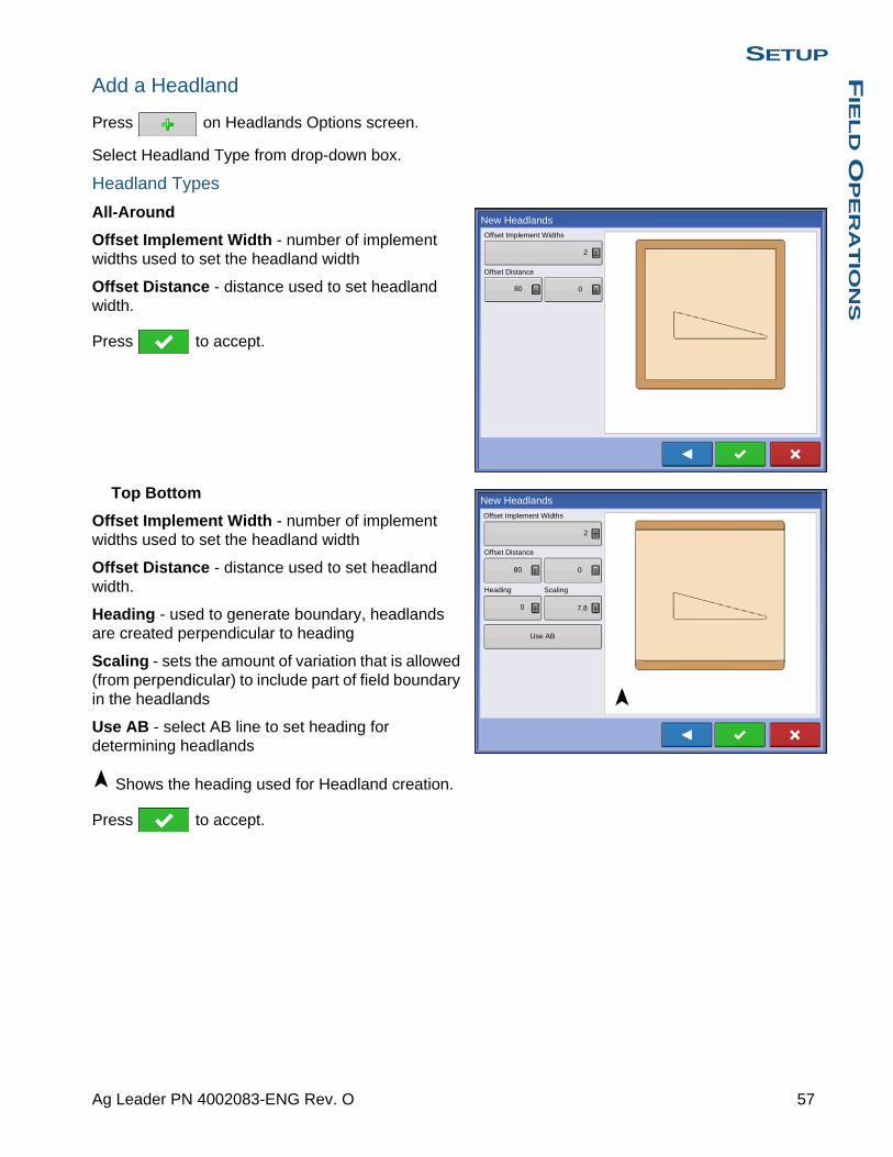
SETUPF
IEL
D O
PE
RA
TIO
NS
Add a Headland
Press on Headlands Options screen.
Select Headland Type from drop-down box.
Headland Types
All-Around
Offset Implement Width - number of implement widths used to set the headland width
Offset Distance - distance used to set headland width.
Press to accept.
Top Bottom
Offset Implement Width - number of implement widths used to set the headland width
Offset Distance - distance used to set headland width.
Heading - used to generate boundary, headlands are created perpendicular to heading
Scaling - sets the amount of variation that is allowed (from perpendicular) to include part of field boundary in the headlands
Use AB - select AB line to set heading for determining headlands
Shows the heading used for Headland creation.
Press to accept.
Offset Implement Widths
New Headlands
2
Offset Distance
80 0
Offset Implement Widths
New Headlands
2
Offset Distance
80 0
Heading
0
Scaling
7.8
Use AB
57 Ag Leader PN 4002083-ENG Rev. O

Driven
1. Select Driven from drop-down menu and press
to continue.
2. Press on New Headlands screen.
3. Input Headland Offset Distance and Direction (Left
or Right). Press to accept.
4. Drive Boundary
• pause
• resume recording after pausing
• stop recording
5. Save, Resume, or Discard
• Save-a. Press Save button
-b. Default name is time and date. Press to change name.
-c. Press to accept or to discard boundary.
• Resume - resume creating boundary
• Discard - discards boundary and returns display to map screen
Load Headlands
Press Load Headlands button.
Select a headland from list.
• Press to delete selected headland
• Press to return to Headland Options
screen
• Press to load selected headland.
New Headlands
Clear All
Load Headlands
Name
2014-01-14_15:25:35
58 Firmware Version 6.3

SETUPF
IEL
D O
PE
RA
TIO
NS
Edit Headlands
Press Edit Headlands button.
Select a headland from list.
• Press to add a driven headland.
• Press to delete selected headland.
• Press to delete all driven headlands.
• Press to return to Headland Options screen.
• Press to load selected headland.
This screen will vary depending on type of headland.
Headland Alarm Settings
Press Headland Alarm Settings button.
Alert Distance - distance from approaching headland at which display will warn user of upcoming headland
Alert Duration - time length from approaching headland at which display will warn user of upcoming headland
Audible Alarms
• Approaching Headland
• Crossing Headland Boundary
Map Screen with Headlands
Edit Headlands
1
Clear All
Alarm Distance
Headland Alarm Settings
Alarm Duration
150 10 s
Audible Alarms
Approaching Headland
Crossing Headland Boundary
0.67 ac 4.5 mph
Reset
traigh Corn1
Corn2
Pass: 2 R
Headland: 113 ft
Nudge: 30.0 in
Total: 0.0 in
59 Ag Leader PN 4002083-ENG Rev. O
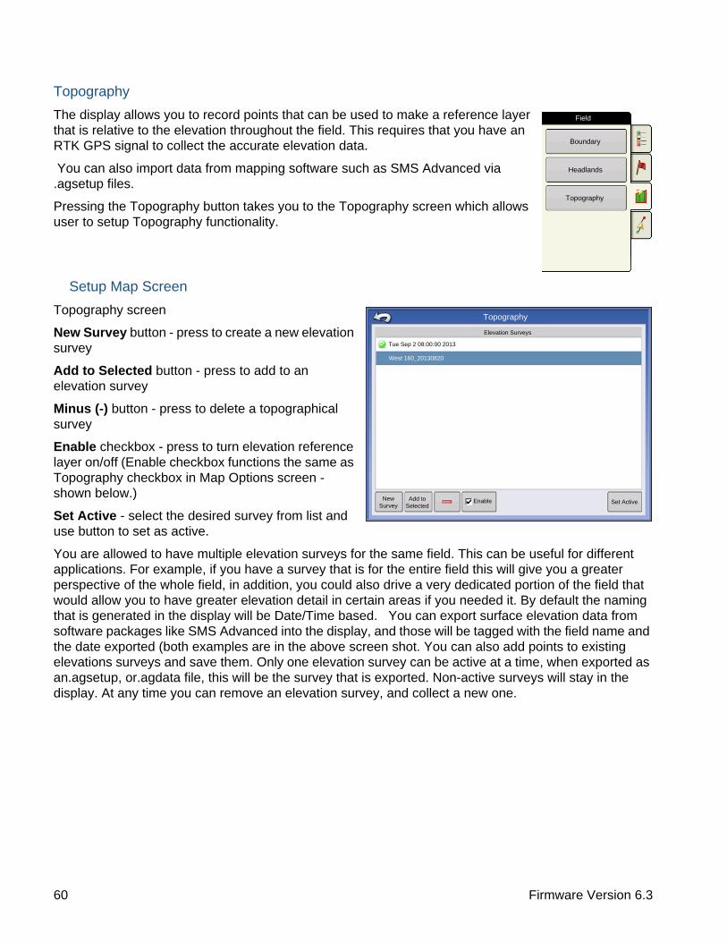
Topography
The display allows you to record points that can be used to make a reference layer that is relative to the elevation throughout the field. This requires that you have an RTK GPS signal to collect the accurate elevation data.
You can also import data from mapping software such as SMS Advanced via .agsetup files.
Pressing the Topography button takes you to the Topography screen which allows user to setup Topography functionality.
Setup Map Screen
Topography screen
New Survey button - press to create a new elevation survey
Add to Selected button - press to add to an elevation survey
Minus (-) button - press to delete a topographical survey
Enable checkbox - press to turn elevation reference layer on/off (Enable checkbox functions the same as Topography checkbox in Map Options screen - shown below.)
Set Active - select the desired survey from list and use button to set as active.
You are allowed to have multiple elevation surveys for the same field. This can be useful for different applications. For example, if you have a survey that is for the entire field this will give you a greater perspective of the whole field, in addition, you could also drive a very dedicated portion of the field that would allow you to have greater elevation detail in certain areas if you needed it. By default the naming that is generated in the display will be Date/Time based. You can export surface elevation data from software packages like SMS Advanced into the display, and those will be tagged with the field name and the date exported (both examples are in the above screen shot. You can also add points to existing elevations surveys and save them. Only one elevation survey can be active at a time, when exported as an.agsetup, or.agdata file, this will be the survey that is exported. Non-active surveys will stay in the display. At any time you can remove an elevation survey, and collect a new one.
Boundary
Field
Headlands
Topography
Topography
Elevation Surveys
West 160_20130820
Tue Sep 2 08:00:00 2013
New Survey
Add to Selected
Enable Set Active
60 Firmware Version 6.3
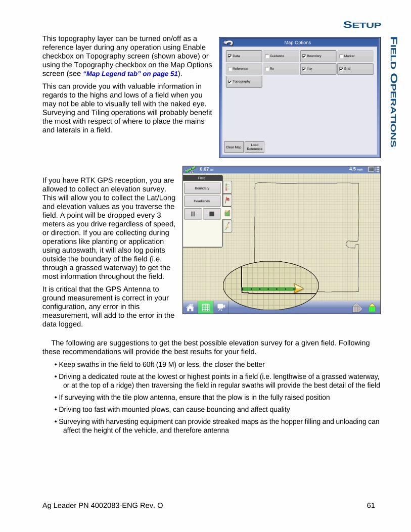
SETUPF
IEL
D O
PE
RA
TIO
NS
This topography layer can be turned on/off as a reference layer during any operation using Enable checkbox on Topography screen (shown above) or using the Topography checkbox on the Map Options screen (see “Map Legend tab” on page 51).
This can provide you with valuable information in regards to the highs and lows of a field when you may not be able to visually tell with the naked eye. Surveying and Tiling operations will probably benefit the most with respect of where to place the mains and laterals in a field.
If you have RTK GPS reception, you are allowed to collect an elevation survey. This will allow you to collect the Lat/Long and elevation values as you traverse the field. A point will be dropped every 3 meters as you drive regardless of speed, or direction. If you are collecting during operations like planting or application using autoswath, it will also log points outside the boundary of the field (i.e. through a grassed waterway) to get the most information throughout the field.
It is critical that the GPS Antenna to ground measurement is correct in your configuration, any error in this measurement, will add to the error in the data logged.
The following are suggestions to get the best possible elevation survey for a given field. Following these recommendations will provide the best results for your field.
• Keep swaths in the field to 60ft (19 M) or less, the closer the better
• Driving a dedicated route at the lowest or highest points in a field (i.e. lengthwise of a grassed waterway, or at the top of a ridge) then traversing the field in regular swaths will provide the best detail of the field
• If surveying with the tile plow antenna, ensure that the plow is in the fully raised position
• Driving too fast with mounted plows, can cause bouncing and affect quality
• Surveying with harvesting equipment can provide streaked maps as the hopper filling and unloading can affect the height of the vehicle, and therefore antenna
Map Options
Load Reference
Data Guidance Boundary Marker
Reference Rx Tile Grid
Topography
Clear Map
Boundary
Headlands
Field
0.67 ac 4.5 mph
61 Ag Leader PN 4002083-ENG Rev. O

After these points have been collected, they will be converted into a surface layer in which you can define the color scheme Red, White, Blue, or Brown-Tan. See “Map Legend tab” on page 51. In the Red, white, blue scheme, the darker blue hues will represent the lower elevation, and the darker red values will represent the higher elevations, white will be a transition color between. In the Brown-Tan scheme, the Dark brown will represent the lower elevations, and the Tan the higher elevations. You can select the number of legend ranges for your field that will show the areas desired. This theme will be used for each field until changed.
During collection of an elevation survey, points will be logged to the file every 3 meters. An onscreen visual will appear in the form of a single black dot every 30 meters.
If at any point during collection your gps correction status changes out of RTK fixed, logging will be suspended, if you re-acquire the RTK signal, logging will automatically resume.
At any point you can pause or stop
collection of the elevation survey, and then resume
as needed.
If you forget to stop logging as you leave the field, you will be prompted with the message that data collection is still active, and be given the option to continue logging, or end operation.
No Product
0.67 ac 4.5 mph
Topography
816 - 819814 - 816811 - 814808 - 814806 - 8080 - 806
the following items are outside the recommended accuracy
GPS Quality Warning
Low Fix Quality
62 Firmware Version 6.3

SETUPF
IEL
D O
PE
RA
TIO
NS
In Odd-shaped fields, the surface rendering of the elevation will connect areas (A) even if you haven’t driven through that area.
VIDEO
• Video buttonPress and the Video screen appears.
• Brightness
Press / to increase or
decrease the brightness of the video input.
• Contrast
Press / to increase or decrease the contrast of the video input.
• Camera Number SelectionThe display can receive input from up to four video cameras. Press the numbered buttons to switch views between video cameras.
Note: You can adjust the brightness and contrast of each input individually.
No Product
0.67 ac 4.5 mph
Topography
816 - 819814 - 816811 - 814808 - 814806 - 8080 - 806
63 Ag Leader PN 4002083-ENG Rev. O

64 Firmware Version 6.3
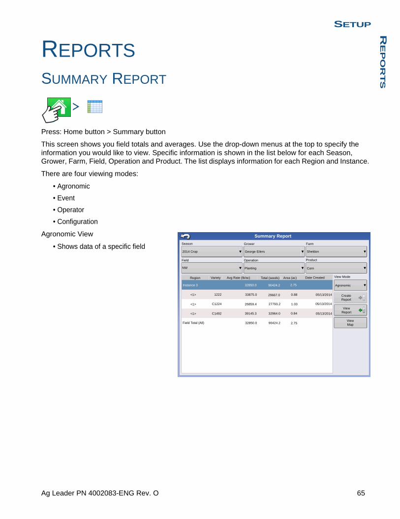
SETUPR
EP
OR
TS
SETUP
REPORTS
SUMMARY REPORT
Press: Home button > Summary button
This screen shows you field totals and averages. Use the drop-down menus at the top to specify the information you would like to view. Specific information is shown in the list below for each Season, Grower, Farm, Field, Operation and Product. The list displays information for each Region and Instance.
There are four viewing modes:
• Agronomic
• Event
• Operator
• Configuration
Agronomic View
• Shows data of a specific field
Avg Rate (lb/ac)
View Report
View Map
Create Report
Season
2014 Crop
Field
Grower
George Eilers
Operation
Planting
Region Date Created
Farm
Product
Corn
Instance 3
Field Total (All)
Summary Report
Agronomic
View ModeArea (ac)Total (seeds)
Sheldon
Variety
<1>
<1>
<1>
1222
C1224
C1492
32850.0
33875.0
26859.4
39145.3
32850.0
27793.2
32964.0
90424.2
0.84
1.03
0.88
2.75
2.7590424.2
29667.0 05/13/2014
05/13/2014
05/13/2014
NW
65 Ag Leader PN 4002083-ENG Rev. O

Event View
• Shows data of a specific Event
Operator View
• Shows data of a specific Operator- Filters data by each configuration
used by the selected operator
• Area Only
• Daily Subtotals
• Configuration Total
• Operator Total
66 Firmware Version 6.3
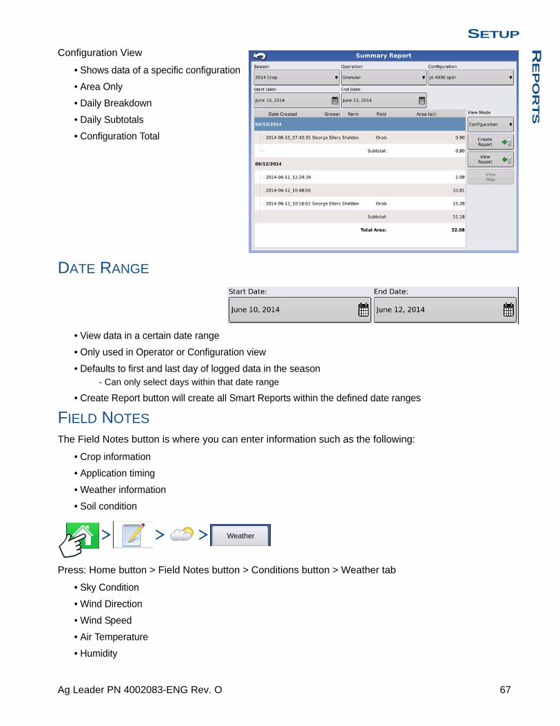
SETUPR
EP
OR
TS
Configuration View
• Shows data of a specific configuration
• Area Only
• Daily Breakdown
• Daily Subtotals
• Configuration Total
DATE RANGE
• View data in a certain date range
• Only used in Operator or Configuration view
• Defaults to first and last day of logged data in the season- Can only select days within that date range
• Create Report button will create all Smart Reports within the defined date ranges
FIELD NOTES
The Field Notes button is where you can enter information such as the following:
• Crop information
• Application timing
• Weather information
• Soil condition
Press: Home button > Field Notes button > Conditions button > Weather tab
• Sky Condition
• Wind Direction
• Wind Speed
• Air Temperature
• Humidity
Weather
67 Ag Leader PN 4002083-ENG Rev. O
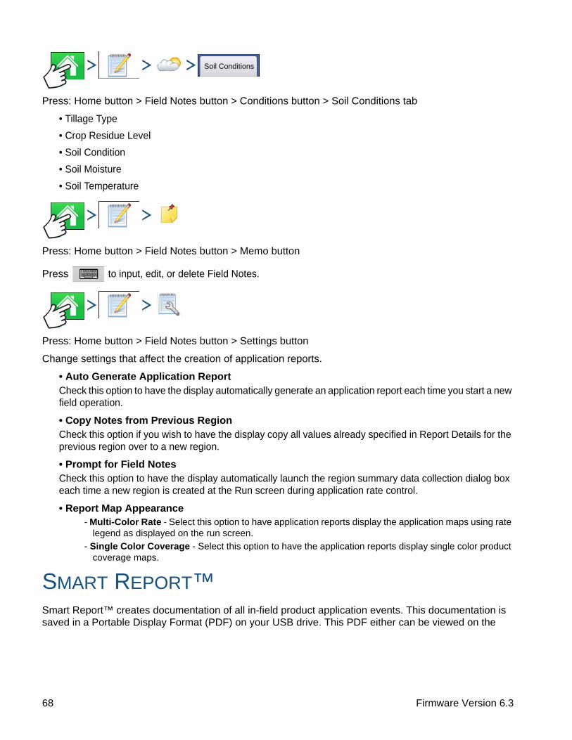
Press: Home button > Field Notes button > Conditions button > Soil Conditions tab
• Tillage Type
• Crop Residue Level
• Soil Condition
• Soil Moisture
• Soil Temperature
Press: Home button > Field Notes button > Memo button
Press to input, edit, or delete Field Notes.
Press: Home button > Field Notes button > Settings button
Change settings that affect the creation of application reports.
• Auto Generate Application ReportCheck this option to have the display automatically generate an application report each time you start a new field operation.
• Copy Notes from Previous RegionCheck this option if you wish to have the display copy all values already specified in Report Details for the previous region over to a new region.
• Prompt for Field NotesCheck this option to have the display automatically launch the region summary data collection dialog box each time a new region is created at the Run screen during application rate control.
• Report Map Appearance- Multi-Color Rate - Select this option to have application reports display the application maps using rate
legend as displayed on the run screen.
- Single Color Coverage - Select this option to have the application reports display single color product coverage maps.
SMART REPORT™Smart Report™ creates documentation of all in-field product application events. This documentation is saved in a Portable Display Format (PDF) on your USB drive. This PDF either can be viewed on the
Soil Conditions
68 Firmware Version 6.3

SETUPR
EP
OR
TS
display screen, or printed later. Smart Report provides information relating to location, product information, applied totals, field areas, as-applied maps and field boundaries.
Note: It is recommended that you enter any necessary information in Report Details before creating a Smart Report.
CREATE REPORTS
To begin creating a Smart Report™, first highlight an item in the list on the Summary Report screen, then press the Create Report button.
1. The Create Report screen appears, which lists the Grower, Field, and Product at top. Two drop-down menus list your Operating Configuration and Product Group. Use the drop-down menus to change
these, if desired. Press when finished.
2. A scroll bar informs you of the progress made when the display compiles the Smart Report.
3. At the conclusion of the Smart Report creation process, a screen states “Report Creation Complete.”
Press or if you wish to view the report press the View Report button. A built-in PDF viewer
displays your Smart Report. An example is shown at “Control Channel Report Content” on page 71.
Note: You can view subsequent pages in the Smart Report by pressing the blue right and left arrows at top right. Also, you can zoom in and out of the Smart Report by pressing on the magnifying glass icons at top left.
4. Product application reports are automatically stored on the external data card at the time of report creation. Reports are created and stored inside folders that are created with the following sequential information provided by the display:
• Ten-digit serial number of the display. Example: 2007250001.
• Grower
• Farm
• Field Name
• Configuration Name
• Unique ID #
• Date of most recent product application. The files date information is listed according to Year, Month, Day.
Example: East 91_Post Sprayer_DirectLiquid_0000177a_060506.pdf.
SMART REPORT AUTO-GENERATION
Press: Home button > Field Notes button > Settings button
Create Report
69 Ag Leader PN 4002083-ENG Rev. O

This screen allows the user to change the settings that affect the creation of application reports.
• Automatically Create Application Report checkbox
Check this option to have the display automatically generate an application report each perform the action in the Creation Trigger drop-down menu.
• Creation Trigger drop-down menu
User can select to generate reports upon Event Change or Event Closed.
If changing products through the field, it is recommended to set the Prompts to Close Event checkbox in Event Options. See “Field Operation Options” on page 46 for more information on setting Prompts to Close Event.
• Export Location
User can select to export the reports to a USB storage device or AgFiniti. This prevents accidentally exporting to the wrong destination.
Auto-generated reports are stored locally within the display and are manually exported to a connected USB media device or AgFiniti. User is warned if connected media device doesn’t match the selected export location.
See “Export Reports” on page 75 for more information on exporting to USB storage
See “Importing and Exporting Files” on page 97 for more information on exporting to AgFiniti.
70 Firmware Version 6.3
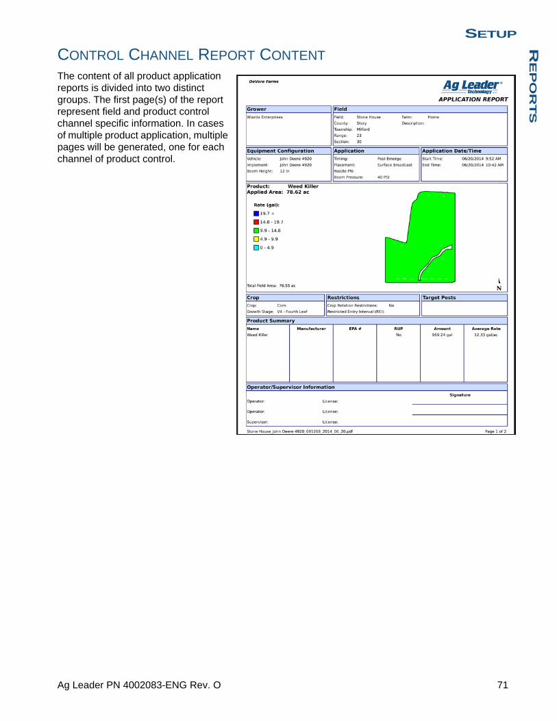
SETUPR
EP
OR
TS
CONTROL CHANNEL REPORT CONTENT
The content of all product application reports is divided into two distinct groups. The first page(s) of the report represent field and product control channel specific information. In cases of multiple product application, multiple pages will be generated, one for each channel of product control.
71 Ag Leader PN 4002083-ENG Rev. O

Control Channel Content includes the following:
• Service Provider Information
• Grower Information
• Field Information
• Farm Name and Description
• Equipment Configuration Information
• Application Information
• Date/Time Information
• Crop Information
• Rotation Restrictions and REI
• Multiple Target Pests
• Applied Product Information
• Operator and Supervisor Information
VIEW REPORTS
To view a Smart Report that has been saved on the USB drive, go to the Summary screen and press the View Report button. At the File Selection screen, scroll down the list and
select the .PDF file of your Smart Report. Press and the Smart Report will appear in
the PDF viewer.
VIEW MAP
To view a Summary Map of a particular Field Total, Region or Instance shown in the Summary Report, press the View Map button. A Summary Map appears. This map shows the rate applied for Application operations and varieties for Planting operations.
View Report
Summary Map
RATE
72 Firmware Version 6.3
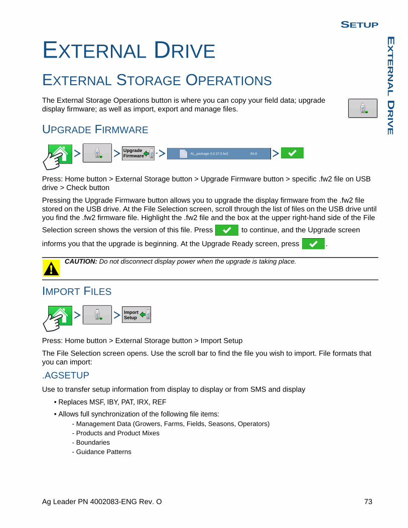
SETUPE
XT
ER
NA
L D
RIV
E
SETUP
EXTERNAL DRIVE
EXTERNAL STORAGE OPERATIONSThe External Storage Operations button is where you can copy your field data; upgrade display firmware; as well as import, export and manage files.
UPGRADE FIRMWARE
-
Press: Home button > External Storage button > Upgrade Firmware button > specific .fw2 file on USB drive > Check button
Pressing the Upgrade Firmware button allows you to upgrade the display firmware from the .fw2 file stored on the USB drive. At the File Selection screen, scroll through the list of files on the USB drive until you find the .fw2 firmware file. Highlight the .fw2 file and the box at the upper right-hand side of the File
Selection screen shows the version of this file. Press to continue, and the Upgrade screen
informs you that the upgrade is beginning. At the Upgrade Ready screen, press .
CAUTION: Do not disconnect display power when the upgrade is taking place.
IMPORT FILES
Press: Home button > External Storage button > Import Setup
The File Selection screen opens. Use the scroll bar to find the file you wish to import. File formats that you can import:
.AGSETUP
Use to transfer setup information from display to display or from SMS and display
• Replaces MSF, IBY, PAT, IRX, REF
• Allows full synchronization of the following file items:- Management Data (Growers, Farms, Fields, Seasons, Operators)
- Products and Product Mixes
- Boundaries
- Guidance Patterns
Upgrade Firmware
AL_package-3.0.37.0.fw2 84.8
Import Setup
73 Ag Leader PN 4002083-ENG Rev. O

• Marker Sets and Markers
Note: Do not use the IBK to “clone” a display. Use AGSETUP.
.AGDATA• Includes all the necessary data to fully archive in SMS
• Includes recorded operation data
• Equipment Used
• Products Used
• Marks Logged
• Boundaries
• Guidance Patterns
• Flexible export options
• Will be able to export by Grower
EXPORT FILES
.AGSETUP
Press: Home button > External Storage button > Export Setup
Use to transfer setup information from display to display or from SMS and display
• Replaces MSF, IBY, PAT, IRX, REF
• Allows full synchronization of the following items:
• Management Data (Growers, Farms, Fields, Seasons, Operators)
• Products and Product Mixes
• Boundaries
• Guidance Patterns
• Marker Sets and Markers
Note: Do not use the IBK to “clone” a display anymore. Use AGSETUP.
.AGDATA
Press: Home button > External Storage button > Export Data
• Includes all the necessary data to fully archive in SMS
• Includes recorded operation data
Export Setup
Export Data
74 Firmware Version 6.3
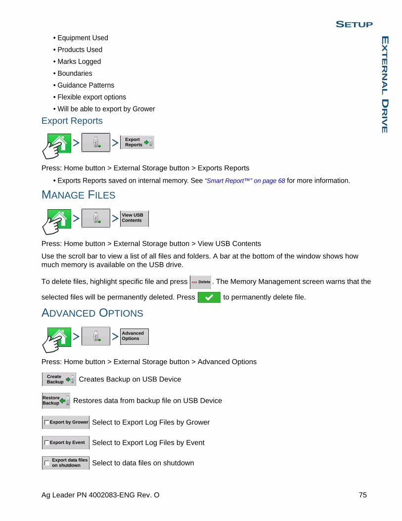
SETUPE
XT
ER
NA
L D
RIV
E
• Equipment Used
• Products Used
• Marks Logged
• Boundaries
• Guidance Patterns
• Flexible export options
• Will be able to export by Grower
Export Reports
Press: Home button > External Storage button > Exports Reports
• Exports Reports saved on internal memory. See “Smart Report™” on page 68 for more information.
MANAGE FILES
Press: Home button > External Storage button > View USB Contents
Use the scroll bar to view a list of all files and folders. A bar at the bottom of the window shows how much memory is available on the USB drive.
To delete files, highlight specific file and press . The Memory Management screen warns that the
selected files will be permanently deleted. Press to permanently delete file.
ADVANCED OPTIONS
Press: Home button > External Storage button > Advanced Options
Creates Backup on USB Device
Restores data from backup file on USB Device
Select to Export Log Files by Grower
Select to Export Log Files by Event
Select to data files on shutdown
Export Reports
View USB Contents
Delete
Advanced Options
Create Backup
Restore Backup
Export by Grower
Export by Event
Export data files on shutdown
75 Ag Leader PN 4002083-ENG Rev. O

Press to Export All Log filesExport All Log Files
76 Firmware Version 6.3
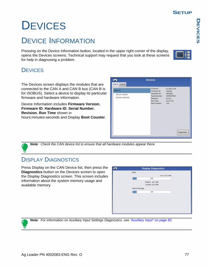
SETUPD
EV
ICE
S
SETUP
DEVICES
DEVICE INFORMATIONPressing on the Device Information button, located in the upper right corner of the display, opens the Devices screens. Technical support may request that you look at these screens for help in diagnosing a problem.
DEVICES
The Devices screen displays the modules that are connected to the CAN A and CAN B bus (CAN B is for ISOBUS). Select a device to display its particular firmware and hardware information.
Device Information includes Firmware Version, Firmware ID, Hardware ID, Serial Number, Revision, Run Time shown in hours:minutes:seconds and Display Boot Counter.
Note: Check the CAN device list to ensure that all hardware modules appear there.
DISPLAY DIAGNOSTICS
Press Display on the CAN Device list, then press the Diagnostics button on the Devices screen to open the Display Diagnostics screen. This screen includes information about the system memory usage and available memory.
Note: For information on Auxiliary Input Settings Diagnostics, see “Auxiliary Input” on page 82.
VERSADISPLAY
232 DC LIQUID
233 AUX DEVICE
Firmware:
Firmware ID:
Hardware ID:
Serial Number:
Revision:
Run Time:
Boot Counter:
1.0.34/1.0.28
40016832009120003
2.0.0.0
112:27:23
476
CAN A CAN B
Devices
Diagnostics
RAM
Buffers: 26.1 MB
Cached: 53.3 MB
Internal Storage
Display Diagnostics
77 Ag Leader PN 4002083-ENG Rev. O

78 Firmware Version 6.3

SETUPS
ET
TIN
GS
SETUP
SETTINGS
EQUIPMENT SETTINGS Press the Configuration Settings button on the Configuration Setup screen to view or edit the name of your Equipment Configuration Settings. The appearance of this button will vary, depending upon whether you are using a Area Logging operating configuration (with or without an implement switch); or whether you are using Rate Logging/Control for a DirectCommand or SeedCommand operating configuration. Area Logging settings are explained below. If you have an operating configuration with Rate Control, see “Equipment Configuration Settings for Rate Control” on page 80.
Implement Switch Settings (for Area Logging)
If you are using an Area Logging (Site Verification) operating configuration (meaning that the configuration does not use Rate Logging or Rate Control) then you must specify an Implement Switch Setting. At the Configuration Setup screen, press the Configuration Settings button.
The Equipment Configuration Settings screen appears.
If you will be using an implement switch choose Standard or Reversed polarity.
If an implement switch is not in use, select None.
Press to return to the Configuration Setup screen.
Equipment Settings
Equipment Configuration Settings
Implement Switch Polarity
Standard
79 Ag Leader PN 4002083-ENG Rev. O

Equipment Configuration Settings for Rate Control
If you are using an operating configuration with Rate Control, (such as for certain DirectCommand and SeedCommand configurations) you must specify Equipment Configuration Settings. At the Configuration Setup screen, press the Configuration Settings button. The Equipment Configuration Settings screen appears.
These settings are directly related to that specific combination of Vehicle, Implement, and Controller.
• The configuration name can be changed by pressing .
• The Rate Outside of Field selection determines product control channel behavior when the field boundary is exited.
- Zero Product - Product application will turn off.
- Last Good - Product application will continue at the last value used by the control system.
- Rx Default - Product will be applied at the default rate setting.
• Rate Display Smoothing settingDetermines how the feedback from the control channel rate sensor will be displayed on the map screen. When de-selected, the system will display raw feedback from the rate sensor. When checked, the system will display target rate when the application rate is within 10% of the target rate setting.
• Rate Change Look-Ahead settingSetting compensates for any latency in the control system and is designed to provide control valve additional time to fully adjust and achieve new rate when transitioning between flow rates during variable rate application. Typical setting rate is 0-1 second.
SPEED INPUT SETTINGS
Press: Home button > Setup (wrench) button > Configuration (tractor) button > Configuration tab > your specific configuration > Setup (wrench) button > Speed Input button
Equipment Configuration Settings
Rate Outside of Field
Rate Display Smoothing
0 sec
Rate Change Look-Ahead
Zero
ConfigurationYour Specific Configuration
Speed Input
80 Firmware Version 6.3
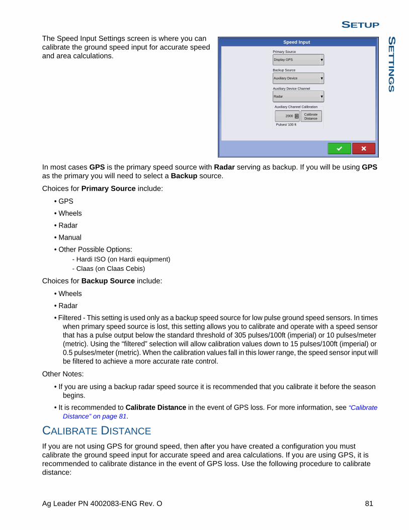
SETUPS
ET
TIN
GS
The Speed Input Settings screen is where you can calibrate the ground speed input for accurate speed and area calculations.
In most cases GPS is the primary speed source with Radar serving as backup. If you will be using GPS as the primary you will need to select a Backup source.
Choices for Primary Source include:
• GPS
• Wheels
• Radar
• Manual
• Other Possible Options:- Hardi ISO (on Hardi equipment)
- Claas (on Claas Cebis)
Choices for Backup Source include:
• Wheels
• Radar
• Filtered - This setting is used only as a backup speed source for low pulse ground speed sensors. In times when primary speed source is lost, this setting allows you to calibrate and operate with a speed sensor that has a pulse output below the standard threshold of 305 pulses/100ft (imperial) or 10 pulses/meter (metric). Using the “filtered” selection will allow calibration values down to 15 pulses/100ft (imperial) or 0.5 pulses/meter (metric). When the calibration values fall in this lower range, the speed sensor input will be filtered to achieve a more accurate rate control.
Other Notes:
• If you are using a backup radar speed source it is recommended that you calibrate it before the season begins.
• It is recommended to Calibrate Distance in the event of GPS loss. For more information, see “Calibrate Distance” on page 81.
CALIBRATE DISTANCE
If you are not using GPS for ground speed, then after you have created a configuration you must calibrate the ground speed input for accurate speed and area calculations. If you are using GPS, it is recommended to calibrate distance in the event of GPS loss. Use the following procedure to calibrate distance:
Primary Source
Display GPS
Backup Source
Auxiliary Device
Speed Input
Auxiliary Device Channel
Radar
Auxiliary Channel Calibration
2000 Calibrate Distance
Pulses/ 100 ft
81 Ag Leader PN 4002083-ENG Rev. O

Press: Home button > Setup (wrench) button > Configuration (tractor) button > Configuration tab > your specific configuration > Setup (wrench) button > Speed Input button > Calibrate Speed Sensor
Follow instructions on screen to calibrate sensor.
Note: Calibration settings can be manually adjusted if desired by pressing Enter CAL Number and making small changes to the setting.
AUXILIARY INPUT
Press: Home button > Setup (wrench) button > Configuration (tractor) button > Configuration tab > your specific configuration > Setup (wrench) button > Auxiliary Input button
This Switch Mapping function is active only for DirectCommand or SeedCommand. The Auxiliary Input Settings screen displays settings for the Master Switch and other switches on a DirectCommand or SeedCommand Switch Box.
Auxiliary Input Settings can be adjusted by going to the Auxiliary Input Summary screen. Go to the Configuration Setup screen and press the Auxiliary Input button. The Auxiliary Input Summary screen appears. This screen lists each switch on a switch box and which functions (if any) are assigned to particular switches.
The Assign button, located at the upper right-hand corner of this screen, opens the Auxiliary Input Assignment screen, where you can assign functions to switches and external inputs. For more information, see “Auxiliary Input Settings” on page 83.
The Master Switch Source drop-down menu controls the master switch for your entire configuration. You may see the following options underneath this menu:
• Switch - Controls the master switch.
• External 2 - This setting can control an optional, floor-mounted master switch.
• External 1, 3 & 4 - Not used at this time.
The F1-F11 switches can be assigned to any implement sections. You can use these to choose the switches that control a particular section or controller planting clutch. You can also make the following changes to the switch settings.
• Add a switch setting. For more information, see “Auxiliary Input Settings” on page 83.
ConfigurationYour Specific Configuration
Speed Input
Calibrate Speed Sensor
ConfigurationYour Specific Configuration
Auxiliary Input
Reset All
F1 (Master)F2 (Switch 1)F3 (Switch 2)F4 (Switch 3)
F5 (Switch 4)F6 (Switch 5)F7 (Switch 6)F8 (Switch 7)
F9 (Switch 8)
F10 (Switch 9)F11 (Switch 10)
External 1External 2
External 3External 4
1
23
DirectLiquid
Auxiliary Input
Switch
Assign
Master Source
82 Firmware Version 6.3
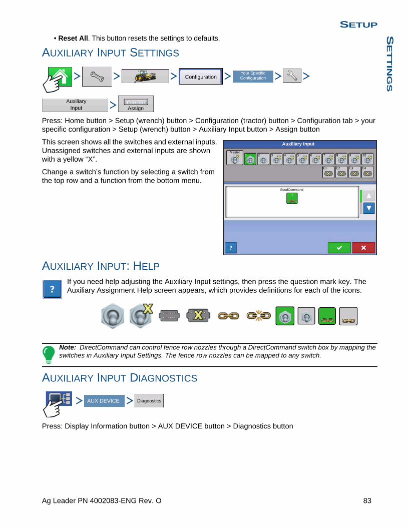
SETUPS
ET
TIN
GS
• Reset All. This button resets the settings to defaults.
AUXILIARY INPUT SETTINGS
Press: Home button > Setup (wrench) button > Configuration (tractor) button > Configuration tab > your specific configuration > Setup (wrench) button > Auxiliary Input button > Assign button
This screen shows all the switches and external inputs. Unassigned switches and external inputs are shown with a yellow “X”.
Change a switch’s function by selecting a switch from the top row and a function from the bottom menu.
AUXILIARY INPUT: HELP
If you need help adjusting the Auxiliary Input settings, then press the question mark key. The Auxiliary Assignment Help screen appears, which provides definitions for each of the icons.
Note: DirectCommand can control fence row nozzles through a DirectCommand switch box by mapping the switches in Auxiliary Input Settings. The fence row nozzles can be mapped to any switch.
AUXILIARY INPUT DIAGNOSTICS
Press: Display Information button > AUX DEVICE button > Diagnostics button
ConfigurationYour Specific Configuration
Auxiliary Input Assign
Master
Auxiliary Input
SeedCommand
AUX DEVICE Diagnostics
83 Ag Leader PN 4002083-ENG Rev. O

The Auxiliary Input Diagnostics screen lists the active switches. These color-coded boxes display the following diagnostics:
• GreenThe switch box is connected to the Auxiliary Module in the On position.
• BlackThe switch box is connected to the Auxiliary Module, but is in the Off position.
• GreyThe switch box is not connected to the Auxiliary Module.
Below the list of switches is the number of Ground Speed Pulses coming in from the radar to the Auxiliary Module.
Technical support may request that you look at this screen for help in diagnosing a problem.
Note: The E2 position is the indicator for the foot box.
AUTOSWATH
Press: Home button > Setup (wrench) button > Configuration (tractor) button > Configuration tab > select your specific configuration > Setup (wrench) button > Automatic Swath Control button
The Automatic Swath Control feature turns sections off and on automatically based upon the following conditions:
• Entering and exiting internal and outer field boundaries.
• Entering and exiting previously-applied areas within a field.
• Outside Boundary OptionSelect one of the two options to determine system behavior when a section exits a field boundary.
• Coverage OptionIn the Coverage Option area, you must choose between three options:
Ground Speed Pulses 0
Auxiliary Input Diagnostic
ConfigurationSelect Your Specific
Configuration
Automatic Swath Control
Automatic Swath Control
Look-Ahead Settings
100 %User Defined
Minimize Overlap
Minimize Skip
Coverage Option
Planting
Outside Boundary Option
Keep Unchanged
Turn Section Off
84 Firmware Version 6.3

SETUPS
ET
TIN
GS
- The Minimize Skip option turns off the implement section after the entire section is fully inside your coverage area. This prevents the possibility of skips.
- The Minimize Overlap option turns off the implement section when that section first enters your coverage area. This prevents the possibility of overlaps.
- The User Defined option allows you to choose what percentage of the implement section is within the coverage area before that section turns off. For example, if you choose 50%, then the section will switch off when half of it is within your coverage area.
Look-Ahead Settings
AutoSwath Control settings are saved per controller per configuration. The Look-Ahead Settings screen will contain every controller’s look-aheads.
On the AutoSwath Control screen, press the Look-Ahead button.
• Turn-OnThis setting determines how far ahead the system looks to turn the sections back on. This setting compensates for delay in the planting control system when the implement sections are turned on.
• Turn-OffThis setting determines how far ahead the system looks to turn the sections off. This setting compensates for delay in the product control system when the sections are turned off.
Note: To use AutoSwath for planting operations, you are required to use a 5 Hz or higher GPS output rate. AutoSwath control will not allow sections to be turned on until the master and planting section switches are on. If you have less than a 5 Hz GPS output rate and you select AutoSwath, a warning appears, telling you
that AutoSwath Control is not available at less than 5 Hz.
Note: If you are performing a Harvest operation, see “AutoSwath Sensitivity Settings” on page 341.
VEHICLE OFFSETS
Press: Home button > Setup (wrench) button > Configuration (tractor) button > Configuration tab > your specific configuration > Setup (wrench) button > Vehicle Offsets button
After completing the process of setting up a Vehicle, you must configure vehicle offsets. The these offsets define where the machine’s rear axle and hitch is in relation to the GPS antenna. These settings are used by mapping.
The GPS Offsets settings consist of two tabs: the Antenna Tab and the Hitch Tab.
Look Ahead Settings
Turn-OnPlantingPlanting Row Shutoff Turn-Off1.1 s 0.4 s
ConfigurationYour Specific Configuration
Vehicle Offsets
85 Ag Leader PN 4002083-ENG Rev. O
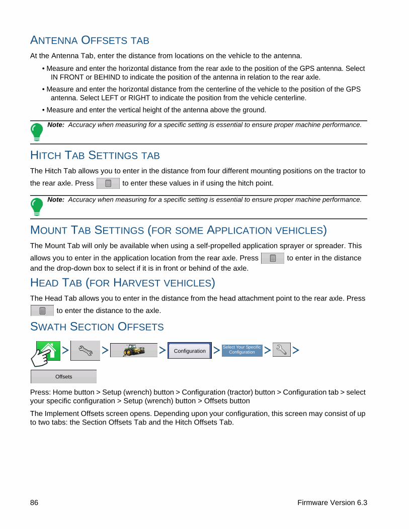
ANTENNA OFFSETS TAB
At the Antenna Tab, enter the distance from locations on the vehicle to the antenna.
• Measure and enter the horizontal distance from the rear axle to the position of the GPS antenna. Select IN FRONT or BEHIND to indicate the position of the antenna in relation to the rear axle.
• Measure and enter the horizontal distance from the centerline of the vehicle to the position of the GPS antenna. Select LEFT or RIGHT to indicate the position from the vehicle centerline.
• Measure and enter the vertical height of the antenna above the ground.
Note: Accuracy when measuring for a specific setting is essential to ensure proper machine performance.
HITCH TAB SETTINGS TAB
The Hitch Tab allows you to enter in the distance from four different mounting positions on the tractor to
the rear axle. Press to enter these values in if using the hitch point.
Note: Accuracy when measuring for a specific setting is essential to ensure proper machine performance.
MOUNT TAB SETTINGS (FOR SOME APPLICATION VEHICLES)The Mount Tab will only be available when using a self-propelled application sprayer or spreader. This
allows you to enter in the application location from the rear axle. Press to enter in the distance
and the drop-down box to select if it is in front or behind of the axle.
HEAD TAB (FOR HARVEST VEHICLES)The Head Tab allows you to enter in the distance from the head attachment point to the rear axle. Press
to enter the distance to the axle.
SWATH SECTION OFFSETS
Press: Home button > Setup (wrench) button > Configuration (tractor) button > Configuration tab > select your specific configuration > Setup (wrench) button > Offsets button
The Implement Offsets screen opens. Depending upon your configuration, this screen may consist of up to two tabs: the Section Offsets Tab and the Hitch Offsets Tab.
ConfigurationSelect Your Specific
Configuration
Offsets
86 Firmware Version 6.3

SETUPS
ET
TIN
GS
Section Offsets
• Press the first to enter the distance that the swath section is located from the hitch point.
• Press the second to enter the distance
from the mid-point of the swath section to the machine’s centerline. Select to the left/to the right to indicate the direction the swath section is located from the vehicle centerline.
• Press when finished.
Note: Accuracy when measuring and entering implement offsets is required to ensure proper machine performance.
Offsets
Planting with SeedCommand 2
Enter Left or Right Distance from Centerline
0 ft Left
Enter Forward or Backward Distance from Hitch Point
Advanced
5 ft
87 Ag Leader PN 4002083-ENG Rev. O

88 Firmware Version 6.3
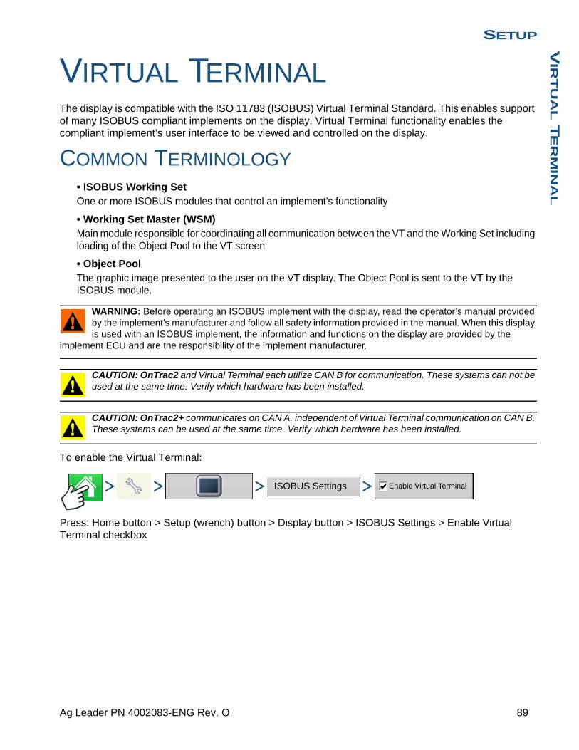
SETUPV
IRT
UA
L T
ER
MIN
AL
SETUP
VIRTUAL TERMINALThe display is compatible with the ISO 11783 (ISOBUS) Virtual Terminal Standard. This enables support of many ISOBUS compliant implements on the display. Virtual Terminal functionality enables the compliant implement’s user interface to be viewed and controlled on the display.
COMMON TERMINOLOGY• ISOBUS Working SetOne or more ISOBUS modules that control an implement’s functionality
• Working Set Master (WSM)Main module responsible for coordinating all communication between the VT and the Working Set including loading of the Object Pool to the VT screen
• Object PoolThe graphic image presented to the user on the VT display. The Object Pool is sent to the VT by the ISOBUS module.
WARNING: Before operating an ISOBUS implement with the display, read the operator’s manual provided by the implement’s manufacturer and follow all safety information provided in the manual. When this display is used with an ISOBUS implement, the information and functions on the display are provided by the
implement ECU and are the responsibility of the implement manufacturer.
CAUTION: OnTrac2 and Virtual Terminal each utilize CAN B for communication. These systems can not be used at the same time. Verify which hardware has been installed.
CAUTION: OnTrac2+ communicates on CAN A, independent of Virtual Terminal communication on CAN B. These systems can be used at the same time. Verify which hardware has been installed.
To enable the Virtual Terminal:
Press: Home button > Setup (wrench) button > Display button > ISOBUS Settings > Enable Virtual Terminal checkbox
ISOBUS Settings Enable Virtual Terminal
89 Ag Leader PN 4002083-ENG Rev. O
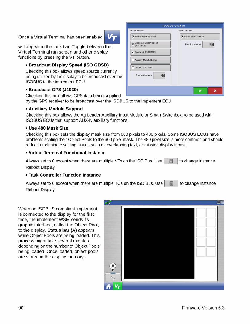
Once a Virtual Terminal has been enabled
will appear in the task bar. Toggle between the Virtual Terminal run screen and other display functions by pressing the VT button.
• Broadcast Display Speed (ISO GBSD)Checking this box allows speed source currently being utilized by the display to be broadcast over the ISOBUS to the implement ECU.
• Broadcast GPS (J1939)Checking this box allows GPS data being supplied by the GPS receiver to be broadcast over the ISOBUS to the implement ECU.
• Auxiliary Module SupportChecking this box allows the Ag Leader Auxiliary Input Module or Smart Switchbox, to be used with ISOBUS ECUs that support AUX-N auxiliary functions.
• Use 480 Mask SizeChecking this box sets the display mask size from 600 pixels to 480 pixels. Some ISOBUS ECUs have problems scaling their Object Pools to the 600 pixel mask. The 480 pixel size is more common and should reduce or eliminate scaling issues such as overlapping text, or missing display items.
• Virtual Terminal Functional Instance
Always set to 0 except when there are multiple VTs on the ISO Bus. Use to change instance.
Reboot Display
• Task Controller Function Instance
Always set to 0 except when there are multiple TCs on the ISO Bus. Use to change instance.
Reboot Display
When an ISOBUS compliant implement is connected to the display for the first time, the implement WSM sends its graphic interface, called the Object Pool, to the display. Status bar (A) appears while Object Pools are being loaded. This process might take several minutes depending on the number of Object Pools being loaded. Once loaded, object pools are stored in the display memory.
Virtual Terminal
Enable Virtual Terminal
Broadcast Display Speed
(ISO GBSD)
Auxiliary Module Support
Task Controller
Enable Task Controller
Function Instance
Function Instance
Use 480 Mask Size
0
ISOBUS Settings
0
Broadcast GPS (J1939)
90 Firmware Version 6.3
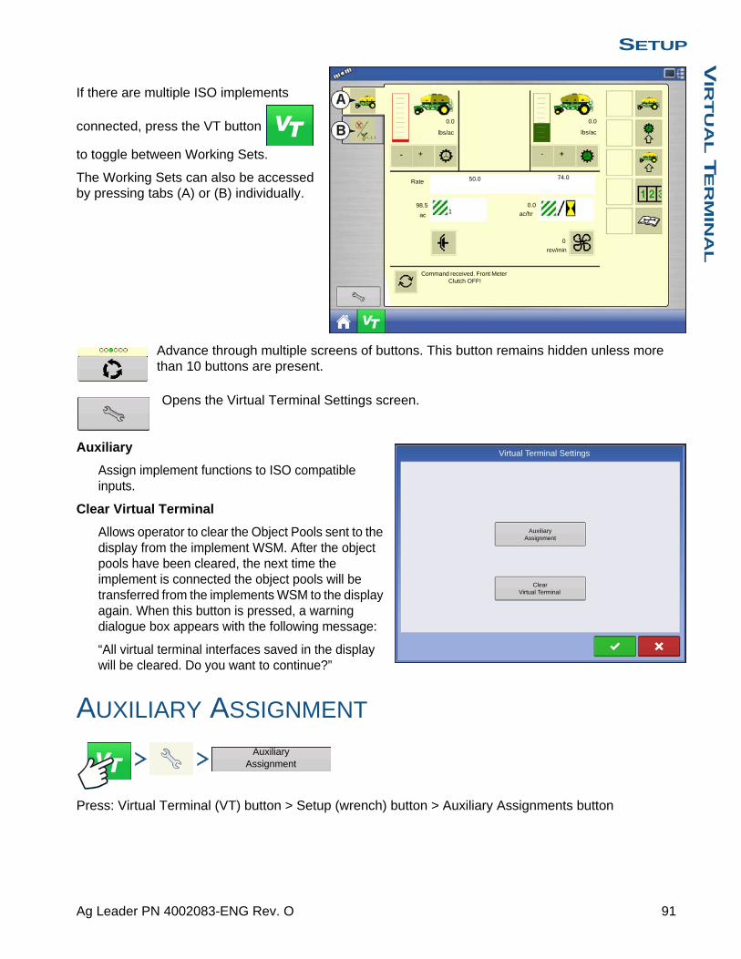
SETUPV
IRT
UA
L T
ER
MIN
AL
If there are multiple ISO implements
connected, press the VT button
to toggle between Working Sets.
The Working Sets can also be accessed by pressing tabs (A) or (B) individually.
Advance through multiple screens of buttons. This button remains hidden unless more than 10 buttons are present.
Opens the Virtual Terminal Settings screen.
Auxiliary
Assign implement functions to ISO compatible inputs.
Clear Virtual Terminal
Allows operator to clear the Object Pools sent to the display from the implement WSM. After the object pools have been cleared, the next time the implement is connected the object pools will be transferred from the implements WSM to the display again. When this button is pressed, a warning dialogue box appears with the following message:
“All virtual terminal interfaces saved in the display will be cleared. Do you want to continue?”
AUXILIARY ASSIGNMENT
Press: Virtual Terminal (VT) button > Setup (wrench) button > Auxiliary Assignments button
lbs/ac
ac ac/hr
lbs/ac
0.0 0.0
Rate 50.0 74.0
98.51
0.0
0
rev/min
Command received. Front Meter Clutch OFF!
Auxiliary Assignment
Virtual Terminal Settings
Clear Virtual Terminal
Auxiliary Assignment
91 Ag Leader PN 4002083-ENG Rev. O

Assign implement functions to ISO compatible inputs.
The number of functions and inputs shown on the Auxiliary Mappings screens will vary depending on the implement and input devices connected to the display.
VT ALARMS AND TROUBLE CODES
If the display receives an active trouble code, the Virtual Terminal Alarm (A) will appear in the Status bar at the top of the screen.
When an alarm is activated on the VT, the display will indicate the alarm by flashing “Virtual Terminal Alarm” in the status bar.
Alarms are acknowledged and cleared by pressing
.
This button is only present when a virtual terminal alarm has been activated.
The Devices screen displays the following information:
• (A) Caution icon indicates module has active trouble codes (DTCs)
• (B) Device Class
• (C) ECU Serial Number
• (D) VT Manufacturer, name and code
Auxiliary Mappings
Function Input
Disable Main Drive Shutoff
Low fan speed detected
Virtual Terminal Alarm
Devices
CAN Name:
Self Configurable: Yes
Industry Group:
Device Class:
Class Instance:
Function:
Function Instance:
A00C80000C202719
Identity Number:
Manufacturer Code:
ECU Instance
CAN A CAN B
Agriculture and
Sprayer
0
128
0
0
10009
97
Forestry
129 ISOBUS Liquid Product Module
Generic ISOBUS
198 WSM 7-Section Aux Input
Ag LeaderTechnology, Inc
Device Name: AGL Sprayer
BoomVolume (Crop Protection)
Diagnostics
92 Firmware Version 6.3

SETUPV
IRT
UA
L T
ER
MIN
AL
Pressing the Diagnostics button on the Devices screen brings up the ISO Node Diagnostics screen which shows the following information.
• SPN “Suspect Parameter Number” = Error Number
• FMI“Fault Mode Indicator” = Error State.
• OC“Occurrence Count”
• DTCDiagnostic Trouble Code
This is a combination of the SPN and the FMI (for example 522102.12).
Cross-reference DTC in equipment manufacturer’s operator manual for description of error.
TASK CONTROLLERWith the addition of Task Controller, a code component within the VT, the system can provide support for functions such as data logging and variable rate application, if the ECU supports TC.
CONFIGURATION SETUP
Press: Home button > Setup (wrench) button > Configuration (tractor) button > Configuration tab > Plus (+) button > Application button.
Configuration setup is the same as Liquid Rate Control and Granular Rate Control (“Create Configuration” on page 223) until Select Controller step. Select ISOBUS controller as follows:
Select ISOBUS as the device
ISO Node Diagnostics
ECU ID:
Software ID: FMA_R 0.9 2006-05-23
Active Errors:
SPN FMI OC
Previously Active Errors:
SPN FMI OC
522102 12 1
523666 3 2
522102
523666
1
23
Clear Previously Active Errors
12
Configuration Application
Controller Setup Wizard: DeviceSelect Controller or Flow Meter
Device
ISOBUS
DirectCommand
Serial Controller
Flow Meter
ISOBUS
93 Ag Leader PN 4002083-ENG Rev. O
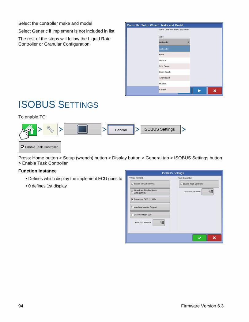
Select the controller make and model
Select Generic if implement is not included in list.
The rest of the steps will follow the Liquid Rate Controller or Granular Configuration.
ISOBUS SETTINGSTo enable TC:
Press: Home button > Setup (wrench) button > Display button > General tab > ISOBUS Settings button > Enable Task Controller
Function Instance
• Defines which display the implement ECU goes to
• 0 defines 1st display
Controller Setup Wizard: Make and Model
Select Controller Make and Model
Make
Mueller
Ag Leader
Horsch
Kverneland
Kuhn-Rauch
Generic
Hardi
John Deere
Ag Leader
General ISOBUS Settings
Enable Task Controller
Virtual Terminal
Enable Virtual Terminal
Broadcast Display Speed
(ISO GBSD)
Auxiliary Module Support
Task Controller
Enable Task Controller
Function Instance
Function Instance
Use 480 Mask Size
0
ISOBUS Settings
0
Broadcast GPS (J1939)
94 Firmware Version 6.3

SETUPA
GF
INIT
I
SETUP
AGFINITI
CONNECTING TO WI-FI NETWORKInsert USB Wi-Fi Adapter to USB port of the display.
To connect to a Wi-Fi network:
Press: Home button > AgFiniti button > Networking button
Select network you wish to use. Secured networks are indicated by a lock on the signal strength icon and require a password.
Press Connect to connect to a network.
If you no longer want to be connected to a network you can press Forget, which will disconnect the network.
No networks in range. User will not be able to connect to a Wi-Fi network when this icon is shown.
Networking
Network Name (SSID)
Wireless Networking
Verizon Tablet
David’s iPad
iPhone
AT&T Mobile HOTSPOT
Office
Connected
Secured with WPA/WPA2
Not Secured
Secured with WEP
Not Secured
Status
Status:
Signal Strength:
Security:
Password
Connected
Excellent
WPA/WPS2
Connect
Forget
95 Ag Leader PN 4002083-ENG Rev. O

One or more networks are in range but display is not configured to connect to a network.
Connected to network. Green bars represent network connection strength: the more green bars, the stronger the network strength. Note: This does not represent cell strength.
CONNECTING TO AGFINITIIn order to connect the display to AgFiniti you must first have an AgFiniti account and active license. If you don’t have an AgFiniti account go to www.AgFiniti.com to create one or use your SMS login credentials. To obtain a license please contact your dealer. First-time AgFiniti users must accept terms of use on www.AgFiniti.com.
To login:
Press: Home button > AgFiniti button > Login button
Your username/password to log into www.AgFiniti.com is the same username/password used on the display.
Not connected to a network: Please connect to a Wi-Fi network
Not logged in to AgFiniti or don’t have a connection to AgFiniti: Login or improve your internet connection. Often caused by poor cellular data coverage areas.
Have a connection to AgFiniti and ready to perform AgFiniti functions.
Press: Home button > AgFiniti button > Advanced Options button
Connection Management
Logout: This will logout the current user of the display so a different user within the same account can login.
Deregister Display: This will remove the AgFiniti licenses associated with this display so the licenses can become available for other displays within the AgFiniti account. This also allows the ability for a different AgFiniti account to be linked to this display.
Once a display has been registered to an AgFiniti account it is linked to that account until the display is de-registered. This de-registration process can be done from the display or from www.AgFiniti.com. Clearing memory on the display will also allow a display to move between accounts.
Login
Advanced Options
AgFiniti Advanced Options
Log Files
Export by Grower
Export by Event
Remote Support
Always Allow
Preauthorize Session
Connection Management
Logout
Deregister Display
Export data files on shutdown
Export All Log Files
96 Firmware Version 6.3
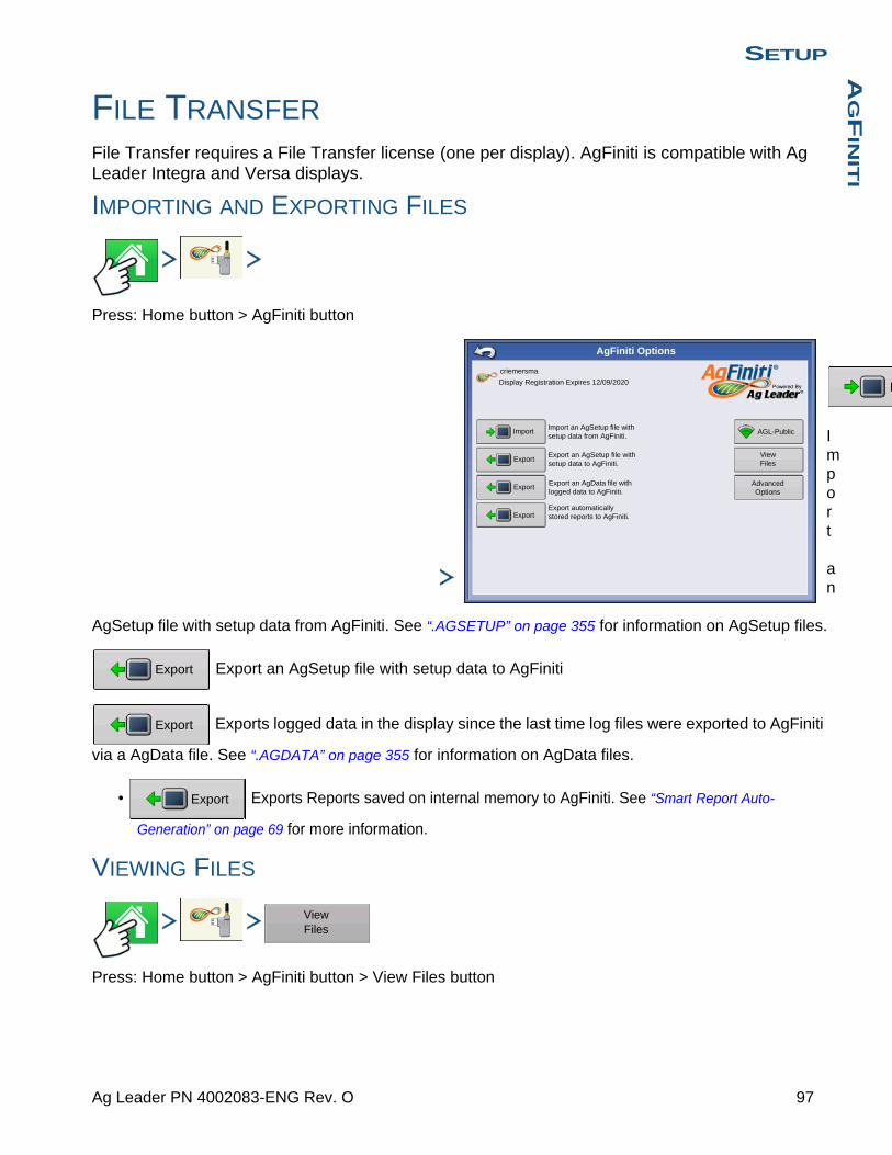
SETUPA
GF
INIT
I
I
FILE TRANSFER
File Transfer requires a File Transfer license (one per display). AgFiniti is compatible with Ag Leader Integra and Versa displays.
IMPORTING AND EXPORTING FILES
Press: Home button > AgFiniti button
Import an
AgSetup file with setup data from AgFiniti. See “.AGSETUP” on page 355 for information on AgSetup files.
Export an AgSetup file with setup data to AgFiniti
Exports logged data in the display since the last time log files were exported to AgFiniti
via a AgData file. See “.AGDATA” on page 355 for information on AgData files.
• Exports Reports saved on internal memory to AgFiniti. See “Smart Report Auto-
Generation” on page 69 for more information.
VIEWING FILES
Press: Home button > AgFiniti button > View Files button
AgFiniti Options
criemersma
Display Registration Expires 12/09/2020
Import
Export
Export
AGL-Public
View Files
Export an AgSetup file with setup data to AgFiniti.
Export an AgData file with logged data to AgFiniti.
Import an AgSetup file with setup data from AgFiniti.
Advanced Options
ExportExport automatically stored reports to AgFiniti.
Export
Export
Export
View Files
97 Ag Leader PN 4002083-ENG Rev. O
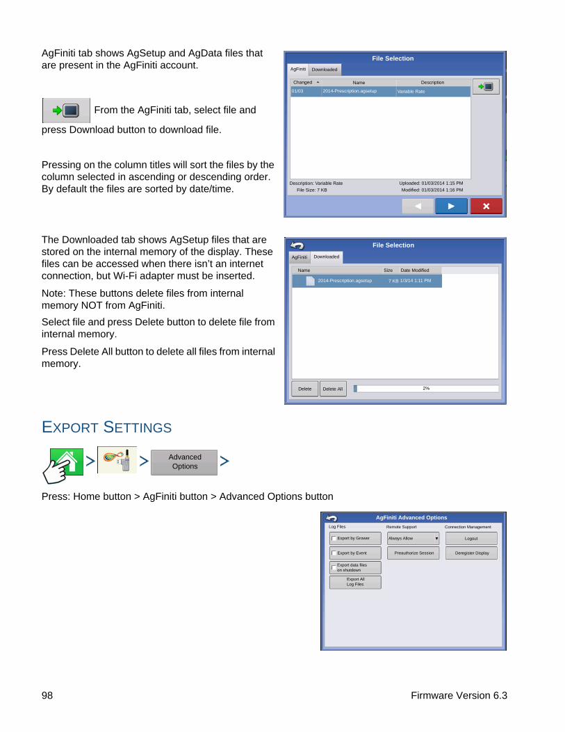
AgFiniti tab shows AgSetup and AgData files that are present in the AgFiniti account.
From the AgFiniti tab, select file and
press Download button to download file.
Pressing on the column titles will sort the files by the column selected in ascending or descending order. By default the files are sorted by date/time.
The Downloaded tab shows AgSetup files that are stored on the internal memory of the display. These files can be accessed when there isn’t an internet connection, but Wi-Fi adapter must be inserted.
Note: These buttons delete files from internal memory NOT from AgFiniti.
Select file and press Delete button to delete file from internal memory.
Press Delete All button to delete all files from internal memory.
EXPORT SETTINGS
Press: Home button > AgFiniti button > Advanced Options button
AgFiniti Downloaded
Changed Name Description
01/03 2014-Prescription.agsetup Variable Rate
Description: Variable Rate
File Size: 7 KB
Uploaded: 01/03/2014 1:15 PM
Modified: 01/03/2014 1:16 PM
File Selection
File Selection
AgFiniti Downloaded
Name
2014-Prescription.agsetup
Size Date Modified
7 KB 1/3/14 1:11 PM
Delete Delete All 2%
Advanced Options
AgFiniti Advanced Options
Log Files
Export by Grower
Export by Event
Remote Support
Always Allow
Preauthorize Session
Connection Management
Logout
Deregister Display
Export data files on shutdown
Export All Log Files
98 Firmware Version 6.3
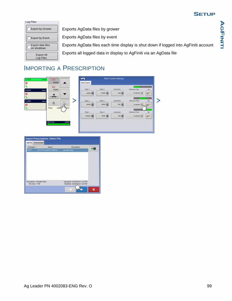
SETUPA
GF
INIT
I
Exports AgData files by grower
Exports AgData files by event
Exports AgData files each time display is shut down if logged into AgFiniti account
Exports all logged data in display to AgFiniti via an AgData file
IMPORTING A PRESCRIPTION
Log Files
Export by Grower
Export by Event
Export data files on shutdown
Export All Log Files
C1222
C1224
C1492
32000
34000
1
2
sds/ac
sds/ac
sds/ac
Flow: 2400
40 ft 0 in 100%
min
Rate 1
Rate 1
Rate 1
Rate 2
Rate 2
Rate 2
32000
36000
400000
34000
38000
42000
500
500
500
Increment
Increment
Increment
Minimum Flow
Minimum Flow
Minimum Flow
0 sds/min
0 sds/min
0 sds/min
Rx
Rx
Rx
Rate Control
Rate Control Settings
Import Prescriptions: Select File
AgFiniti Downloaded
Name
2014-Prescription.agsetup 7 KB 1/3/14 1:11 PM
Changed Description
01/03 2014-Prescription.agsetup Variable Rate
Description: Variable RateFile Size: 7 KB
Uploaded: 01/03/2014 1:16 PMModified: 01/03/2014 1:16 PM
99 Ag Leader PN 4002083-ENG Rev. O

IMPORTING A VARIETY REFERENCE MAP (HARVEST ONLY)from Options screen in the Event Wizard
Press the “Select Event” button and follow the steps in the wizard until screen with Import Variety Map button.
REMOTE SUPPORTRemote Support requires a Remote Support license (one per account). AgFiniti is compatible with Ag Leader Integra and Versa displays.
Remote viewer has no control over the display. Remote viewer can only view the display and not press buttons.
Green border will always appear around the screen when the display is being viewed remotely.
Remote Support Preauthorization
Press: Home button > AgFiniti button > Advanced Options button > Preauthorize Session
Pressing the “Preauthorize Session” button will generate a 10 digit code that can be verbally communicated to remote viewer to initiate the viewing session.
REMOTE SUPPORT PERMISSIONS OPTIONS
Select Event
OptionsRegion
Variety Tracking
Automatic Variety Tracking
Automatic Region Changing
C1224
Import Variety Map
Import Reference: Select AgSetup File
AgFiniti Downloaded
NameChanged Description
01/03 2014-Prescription.agsetup Spring Planting Maps
Description: Spring Planting MapsFile Size: 7 KB
Uploaded: 01/03/2014 1:16 PMModified: 01/03/2014 1:16 PM
Advanced Options
Preauthorize Session
Remote Support
Contact the person you would like to allow to view the display, and provide the following authorization code:
2088D-0568D
Advanced Options
Always Allow
100 Firmware Version 6.3

SETUPA
GF
INIT
I
Press: Home button > AgFiniti button > Advanced Options button > Always Allow
Allows remote viewer to view display screens without display user having to give permission
Press: Home button > AgFiniti button > Advanced Options button > Ask For Permission
This selection will require the display user to grant remote user permission to view the display.
allow remote viewer access to view the display
deny remote viewer access to view the display
If buttons are grayed out then there isn’t a remote support license tied to the AgFiniti account. Must enter Remote Support activation code at www.AgFiniti.com. See dealer for activation code.
Advanced Options
Ask For Permission
Allow John Doe to remotely view the display?
Remote View
101 Ag Leader PN 4002083-ENG Rev. O

102 Firmware Version 6.3

G
PS
GPS
GPSGPS BUTTON
During your field operation, the GPS (satellite) button in the upper left-hand side of the Status Bar should appear green, which means you are receiving a differential GPS signal. If this icon appears yellow, you are still receiving GPS but are not receiving a differential
signal; and if it appears gray then you have lost GPS. In either case, you should check your GPS settings.
SETUP
Press: Home button > Setup (wrench) button > GPS button
Guidance/Steering, Lightbar Settings, and Required Differential Correction for Guidance
For more information, see the Guidance chapter at “Guidance” on page 125.
SERIAL GPS SETTINGS
Press: Home button > Setup (wrench) button > GPS button > Serial (from Receiver drop-down box) > Receiver Setup (wrench) button > General tab
Require Differential Correction for Guidance
Steering
Manual Guidance
Operator Presence Alarm
15 Minutes
Serial
Receiver: 6500
0
GPS/Guidance Setup
Lightbar Settings
Receiver: GPS 6500
Serial General
103 Ag Leader PN 4002083-ENG Rev. O

• Differential SourceSelect choice of WAAS/EGNOS, Satellite (TerraStar®), Glide, RTK, or RTK External differential sources.
• Wrench buttonPressing the Wrench button opens different settings screens, depending on the differential source selected.
• Age of DifferentialDisplays the elapsed time since reception of last differential correction signal. The Age of Differential button is only functional when GPS is connected.
• StableLoc checkboxStableLoc maintains accurate steering – even when your correction signal is temporarily lost – by seamlessly transitioning to the next available signal source. When the signal is restored, the system will then transition back to the higher accuracy source, eliminating position jumps.
• StableLoc Error Limit (RTK & TerraStar only)When using StableLoc, select the error limit at which the system will no longer allow steering. If your error limit is “4 in (10 cm)” and the system accuracy reaches that limit, steering will no longer be allowed until the error decreases. If set to “none” accuracy of the differential source will not affect the ability to autosteer.
• Reset to DefaultsPress the Reset to Defaults button to restore receiver settings to the factory default. This will remove all custom settings.
• NMEA TalkerThis button disables the GLONASS prefix in the NMEA messages. If using the GPS receiver with legacy displays or a device that does not support GLONASS messages, uncheck the box.
Note: If using OmniSTAR, see “OmniSTAR Settings” on page 118.
Upgrade Receiver
Features
Reset to Defaults
Age of Differential
Differential Source
StableLoc
GPS Settings
StableLoc Error Limit
RTK
General Port A (Connected) Port B
2 in 4 in 6 in 8 in 12 in None
NMEA Talker
60
104 Firmware Version 6.3

G
PS
DIFFERENTIAL SOURCE
WAAS/EGNOS Settings
Press: Home button > Setup (wrench) button > GPS button > Serial (from Receiver drop-down box) > Receiver Setup (wrench) button > General tab > WAAS/EGNOS (from Differential Correction drop-down box) > Differential Source Setup (wrench) button
• PRN- Automatic
- WAAS
- EGNOS
- Custom
Upgrade Receiver
Features
Reset to Defaults
RTK External
WAAS/EGNOS
Differential Source
RTK
TerraStar
GPS Settings
GLIDE
TerraStar
General Port A (Connected) Port B
NMEA Talker
Receiver: GPS 6500
Serial General
Differential Source
WAAS/EGNOS
PRN
Automatic
WAAS/EGNOS Settings
105 Ag Leader PN 4002083-ENG Rev. O
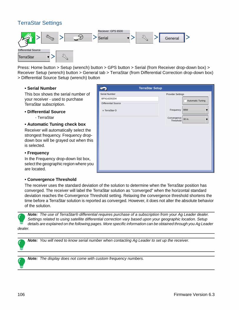
TerraStar Settings
Press: Home button > Setup (wrench) button > GPS button > Serial (from Receiver drop-down box) > Receiver Setup (wrench) button > General tab > TerraStar (from Differential Correction drop-down box) > Differential Source Setup (wrench) button
• Serial NumberThis box shows the serial number of your receiver - used to purchase TerraStar subscription.
• Differential Source- TerraStar
• Automatic Tuning check boxReceiver will automatically select the strongest frequency. Frequency drop-down box will be grayed out when this is selected.
• FrequencyIn the Frequency drop-down list box, select the geographic region where you are located.
• Convergence ThresholdThe receiver uses the standard deviation of the solution to determine when the TerraStar position has converged. The receiver will label the TerraStar solution as “converged” when the horizontal standard deviation reaches the Convergence Threshold setting. Relaxing the convergence threshold shortens the time before a TerraStar solution is reported as converged. However, it does not alter the absolute behavior of the solution.
Note: The use of TerraStar® differential requires purchase of a subscription from your Ag Leader dealer. Settings related to using satellite differential correction vary based upon your geographic location. Setup details are explained on the following pages. More specific information can be obtained through you Ag Leader
dealer.
Note: You will need to know serial number when contacting Ag Leader to set up the receiver.
Note: The display does not come with custom frequency numbers.
Reciever: GPS 6500
Serial General
Differential Source
TerraStar
Serial Number
BFN14200204
Differential Source
TerraStar-D
Provider Settings
Automatic Tuning
Frequency 98W
30 in.
TerraStar Setup
Convergence Threshold
106 Firmware Version 6.3

G
PS
RTK External Settings
Press: Home button > Setup (wrench) button > GPS button > Serial (from Receiver drop-down box) > Receiver Setup (wrench) button > General tab > RTK External (from Differential Correction drop-down box) > Differential Source Setup (wrench) button
Setting the differential source to RTK External enables GGA NMEA message output on Port B at 1 Herz (Hz).
RTK Settings - NTRIP
Press: Home button > Setup (wrench) button > GPS button > Serial (from Receiver drop-down box) > Receiver Setup (wrench) button > General tab > RTK (from Differential Correction drop-down box) > Differential Source Setup (wrench) button
Reciever: GPS 6500
Serial General
Differential Source
RTK External
Radio Baud Rate
Radio Settings
38400
Reciever: GPS 6500
Serial General
Differential Source
RTK
107 Ag Leader PN 4002083-ENG Rev. O
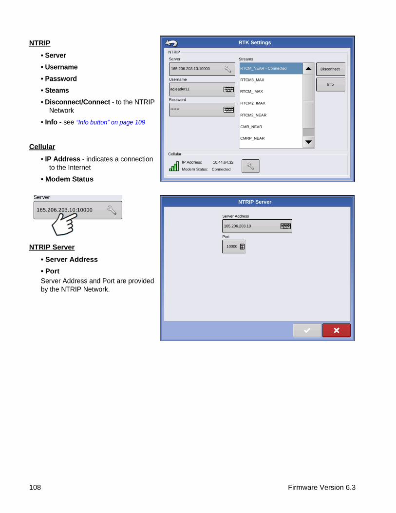
NTRIP
• Server
• Username
• Password
• Steams
• Disconnect/Connect - to the NTRIP Network
• Info - see “Info button” on page 109
Cellular
• IP Address - indicates a connection to the Internet
• Modem Status
NTRIP Server
• Server Address
• PortServer Address and Port are provided by the NTRIP Network.
NTRIP
RTK Settings
Server
165.206.203.10:10000
Username
agleader11
Password
******
Cellular
IP Address:
Modern Status:
10.44.64.32
Connected
RTCM_NEAR - Connected
RTCM3_MAX
RTCM_IMAX
RTCM2_IMAX
RTCM2_NEAR
CMR_NEAR
CMRP_NEAR
Disconnect
Info
Streams
Server Address
NTRIP Server
165.206.203.10
Port
10000
108 Firmware Version 6.3
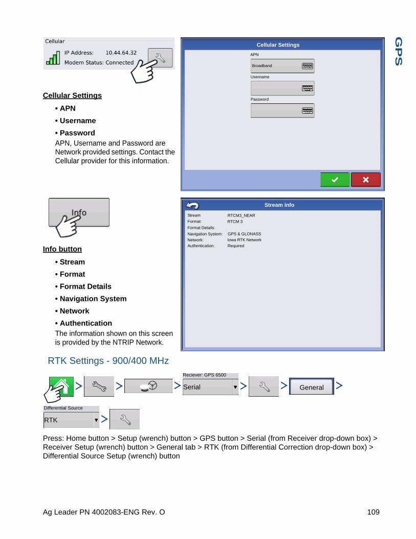
G
PS
Cellular Settings
• APN
• Username
• PasswordAPN, Username and Password are Network provided settings. Contact the Cellular provider for this information.
Info button
• Stream
• Format
• Format Details
• Navigation System
• Network
• AuthenticationThe information shown on this screen is provided by the NTRIP Network.
RTK Settings - 900/400 MHz
Press: Home button > Setup (wrench) button > GPS button > Serial (from Receiver drop-down box) > Receiver Setup (wrench) button > General tab > RTK (from Differential Correction drop-down box) > Differential Source Setup (wrench) button
APN
Cellular Settings
Broadband
Username
Password
Stream
Stream Info
Format:
Format Details:
Navigation System:
Network:
Authentication:
RTCM3_NEAR
RTCM 3
GPS & GLONASS
Iowa RTK Network
Required
Reciever: GPS 6500
Serial General
Differential Source
RTK
109 Ag Leader PN 4002083-ENG Rev. O
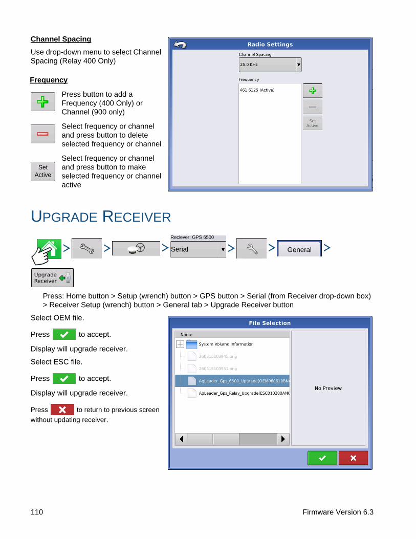
Channel Spacing
Use drop-down menu to select Channel Spacing (Relay 400 Only)
UPGRADE RECEIVER
Press: Home button > Setup (wrench) button > GPS button > Serial (from Receiver drop-down box) > Receiver Setup (wrench) button > General tab > Upgrade Receiver button
Select OEM file.
Press to accept.
Display will upgrade receiver.
Select ESC file.
Press to accept.
Display will upgrade receiver.
Press to return to previous screen
without updating receiver.
Frequency
Press button to add a Frequency (400 Only) or Channel (900 only)
Select frequency or channel and press button to delete selected frequency or channel
Select frequency or channel and press button to make selected frequency or channel active
Set Active
Reciever: GPS 6500
Serial General
110 Firmware Version 6.3
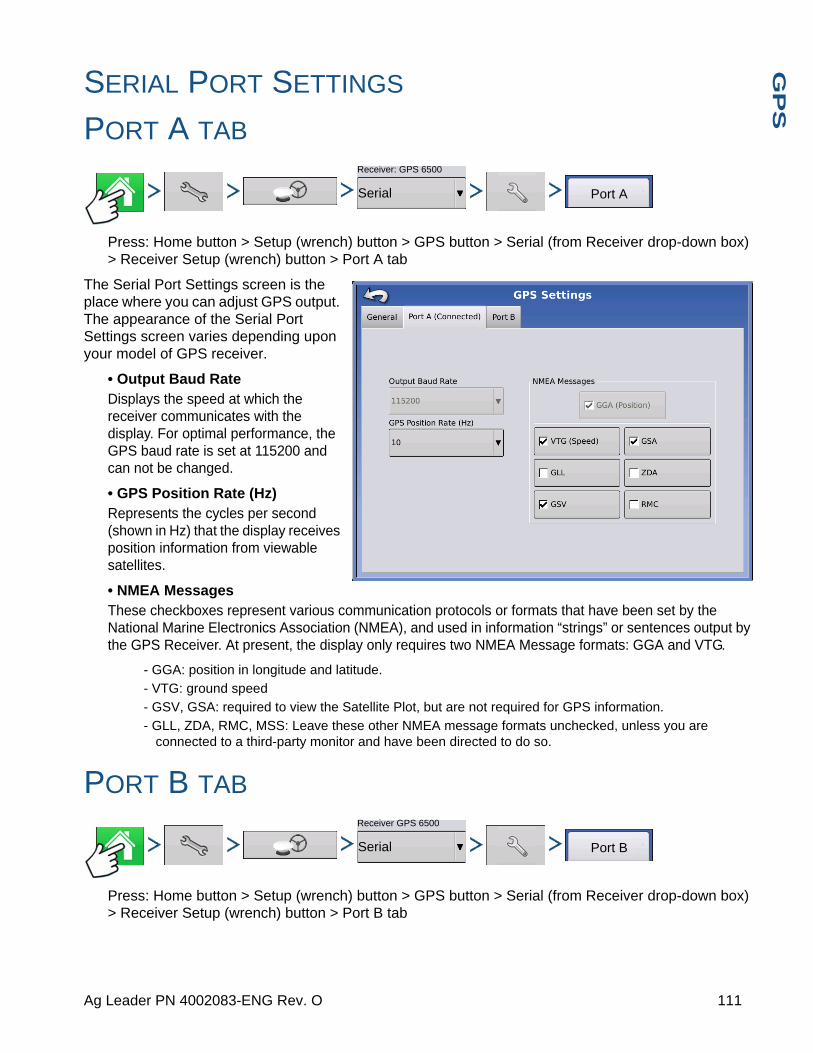
G
PS
SERIAL PORT SETTINGS
PORT A TAB
Press: Home button > Setup (wrench) button > GPS button > Serial (from Receiver drop-down box) > Receiver Setup (wrench) button > Port A tab
The Serial Port Settings screen is the place where you can adjust GPS output. The appearance of the Serial Port Settings screen varies depending upon your model of GPS receiver.
• Output Baud RateDisplays the speed at which the receiver communicates with the display. For optimal performance, the GPS baud rate is set at 115200 and can not be changed.
• GPS Position Rate (Hz)Represents the cycles per second (shown in Hz) that the display receives position information from viewable satellites.
• NMEA MessagesThese checkboxes represent various communication protocols or formats that have been set by the National Marine Electronics Association (NMEA), and used in information “strings” or sentences output by the GPS Receiver. At present, the display only requires two NMEA Message formats: GGA and VTG.
- GGA: position in longitude and latitude.
- VTG: ground speed
- GSV, GSA: required to view the Satellite Plot, but are not required for GPS information.
- GLL, ZDA, RMC, MSS: Leave these other NMEA message formats unchecked, unless you are connected to a third-party monitor and have been directed to do so.
PORT B TAB
Press: Home button > Setup (wrench) button > GPS button > Serial (from Receiver drop-down box) > Receiver Setup (wrench) button > Port B tab
Receiver: GPS 6500
Serial Port A
Receiver GPS 6500
Serial Port B
111 Ag Leader PN 4002083-ENG Rev. O

The appearance of the Port B tab is similar to Ports A.
GGA(Legacy) - shortens the decimal precision of the GGA message for connection to legacy equipment.
The appearance of this TSIP receiver GPS Port Setup screen is the same for both Ports A and B.
GPS INFORMATIONTo access diagnostic information about the GPS signal, press the GPS (satellite) button that appears in the in the upper left-hand side of the Status Bar. GPS Information then appears on General, Receiver, and OmniSTAR tabs. Information on these GPS Information
screens is described on the following pages.
GPS button with bars - bars indicate cellular signal strength
GPS Port Setup - PORT A
Output Type
Output Baud Rate
Output Parity
GPS Pos. Rate (Hz)
Output Rate (Hz) ASAP
1
None
4800
TSIPNMEA Messages
GGA (Position)
VTG (Speed)
GLL
GSV MSS
RMC
ZDA
GSA
112 Firmware Version 6.3

G
PS
GPS INFORMATION - GENERAL TAB
Press: GPS (satellite) button > General tab
• Latitude, Longitude, ElevationDisplays current position (in longitude and latitude) and elevation.
• HeadingDisplays degree heading of travel.
• Number of Satellites
• Differential- No Diff: Indicates the receiver is not receiving a differential GPS signal.
- Diff On: Indicates the receiver is receiving a differential GPS signal.
- GLIDE (GPS 6000/GPS 6500 Only)
- WAAS/EGNOS
- TerraStar-D (GPS 6500 Only)
- RTK Fixed: The receiver is receiving a valid RTK differential source.
- RTK Float: The receiver is receiving information from the Base Station, but the signal is not strong enough for an RTK fix.
• GPS Speed
• Position RateThe frequency that the receiver is sending the display your position in longitude and latitude (GGA). For example, at 5 Hz the display would be receiving a position message 5 times every second.
• Speed/Heading Rate:The frequency that the receiver is sending the display your ground speed and heading (VTG)
Note: Position Rate and Speed/Heading Rate should both be set at a minimum of 5 Hz for guidance or steering.
• Change Longitude/Latitude FormatPressing this button changes the Longitude/Latitude format. These can either be shown in Degrees, Minutes and Seconds; or Decimal Degrees.
• View Messages button - see “GPS Messages” on page 114.
• UTC TimeUTC is an acronym for Coordinated Universal Time, a high-precision atomic time standard that defines local time throughout the world. Different versions of universal time use atomic clocks to correct for irregularities in the Earth's rotation and orbit. UTC is used in navigation, astronomy, aviation, Internet broadcasts, and amateur radio. If you are receiving information from the satellite, then the UTC Time should automatically update.
General
View Messages
113 Ag Leader PN 4002083-ENG Rev. O
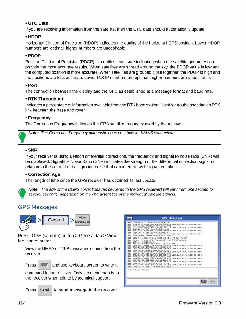
• UTC DateIf you are receiving information from the satellite, then the UTC date should automatically update.
• HDOPHorizontal Dilution of Precision (HDOP) indicates the quality of the horizontal GPS position. Lower HDOP numbers are optimal, higher numbers are undesirable.
• PDOPPosition Dilution of Precision (PDOP) is a unitless measure indicating when the satellite geometry can provide the most accurate results. When satellites are spread around the sky, the PDOP value is low and the computed position is more accurate. When satellites are grouped close together, the PDOP is high and the positions are less accurate. Lower PDOP numbers are optimal, higher numbers are undesirable.
• PortThe connection between the display and the GPS as established at a message format and baud rate.
• RTK ThroughputIndicates a percentage of information available from the RTK base station. Used for troubleshooting an RTK link between the base and rover.
• FrequencyThe Correction Frequency indicates the GPS satellite frequency used by the receiver.
Note: The Correction Frequency diagnostic does not show for WAAS connections.
• SNRIf your receiver is using Beacon differential corrections, the frequency and signal to noise ratio (SNR) will be displayed. Signal-to- Noise Ratio (SNR) indicates the strength of the differential correction signal in relation to the amount of background noise that can interfere with signal reception.
• Correction AgeThe length of time since the GPS receiver has obtained its last update.
Note: The age of the DGPS corrections (as delivered to the GPS receiver) will vary from one second to several seconds, depending on the characteristics of the individual satellite signals.
GPS Messages
Press: GPS (satellite) button > General tab > View Messages button
View the NMEA or TSIP messages coming from the receiver.
Press and use keyboard screen to write a
command to the receiver. Only send commands to the receiver when told to by technical support.
Press to send message to the receiver.
GeneralView
Messages
Send
114 Firmware Version 6.3

G
PS
SATELLITE PLOTPress: GPS (satellite) button > General tab > Satellite Plot button
The Satellite Plot feature can display either as a plot or a graph. The information on these screens is used as an advanced diagnostic tool for GPS satellite availability. In the event of GPS availability issues, technical support may request you to view these screens.
Satellite Plot - Graph
Satellite Plot requires GSV and GSA NMEA messages to be turned on from the GPS receiver.
Note: In order to use Differential GPS, you must have at least four available satellites. In order to use RTK differential sources, you must have at least five available satellites.
GPS INFORMATION - RECEIVER TAB
Press: GPS (satellite) button > Receiver tab
• Receiver ID
• Firmware Version
• Product Serial Number
• Internal Serial Number
• TerraStar Unlocked
• RTK Unlocked
General Satellite Plot
Plot Graph
PRN Elv Azm SNR
Satellites in View 10
Satellites Tracked 7
Corrections Age (sec) 7.40VDOP 2.40
HDOP 1.50
PDOP 2.80
Satellite Plot
Plot Graph
Satellites in View 10Satellites Tracked 7
Corrections Age (sec) 7.40
VDOP 2.40HDOP 1.50
PDOP 2.80
Satellite Plot
SNR
PRN
Receiver
115 Ag Leader PN 4002083-ENG Rev. O

GPS INFORMATION - DIFFERENTIAL TAB
Press: GPS (satellite) button > Differential tab
• Latitude, Longitude, ElevationDisplays current position (in longitude and latitude) and elevation.
Differential Tab:
• Active Estimated ErrorEstimated error of the active differential source.
• Active DifferentialIndicates the active differential source and will vary depending on the current state of StableLoc.
• Selected DifferentialIndicates the selected differential source (the source selected in the GPS setup).
• StableLoc Error LimitIndicates the error limit selected in the GPS setup.
• Device NameIndicates the connected Relay Module.
• Software VersionSoftware version of the radio/modem within the Relay Module.
• ManufacturerManufacturer of the Relay Module.
• Serial NumberSerial number of the Relay Module.
• Signal Strength
• Mobile Directory Number
• Mobile Subscriber ID
• NTRIP Connect/Disconnect
• RTK ConvergenceThree states to indicate the current convergence level.
- Red Arrows, pointing out
The device is not currently converging on RTK. This may indicate a RTK link problem.
- Green Arrows, pointing in
The device is currently converging.
- Green Bull’s-eye
The device is converged on RTK.
Differential
116 Firmware Version 6.3

G
PS
Press: GPS (satellite) button > Base Station tab
• Latitude
• Longitude
• Distance to Base
• Common Satellites
GPS INFORMATION - OMNISTAR TAB
Press: GPS (satellite) button > Relay tab
• HP/XP Expiration Date
• HP/XP Time Remaining
• VBS Expiration Date
• VBS Time Remaining
• AutoSeed Fast Restart
• AutoSeed Status
• Estimated Position Error
RTK/NTRIP Information (ParaDyme/GeoSteer Only)
The following information appears on the second GPS Information screen for RTK or NTRIP.
• Convergence (%)Successful communication between Base Station and ParaDyme Roof Module.
• Radio ThroughputDisplays percentage of data received from Base Station.
• Distance to BaseShows distance to Base Station in miles (kilometers).
• Base ChannelDisplays Channel ID of Base Station.
• NTRIP(NTRIP users only) Shows either Connected or Disconnected.
Base Station
Reset AutoSeed
General Receiver OmniStar
HP/XP Expiration Date:
HP/XP Time Remaining:
VBS Time Remaining:
AutoSeed Fast Restart:AutoSeed Status:
Estimated Position Error:
03/19/2010
0 Days03/19/2010
0 Days
OFF
N/A
N/A
VBS Time Remaining:
GPS InformationOmniStar
117 Ag Leader PN 4002083-ENG Rev. O
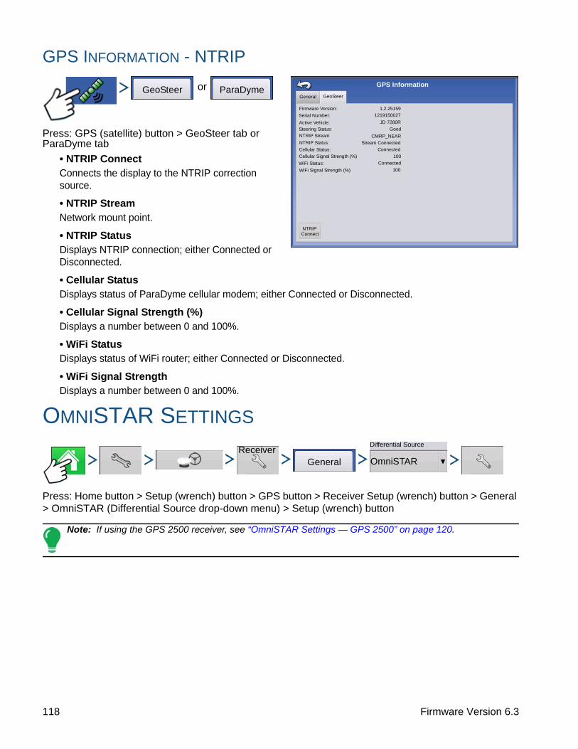
GPS INFORMATION - NTRIP
or
Press: GPS (satellite) button > GeoSteer tab or ParaDyme tab
• NTRIP ConnectConnects the display to the NTRIP correction source.
• NTRIP StreamNetwork mount point.
• NTRIP StatusDisplays NTRIP connection; either Connected or Disconnected.
• Cellular StatusDisplays status of ParaDyme cellular modem; either Connected or Disconnected.
• Cellular Signal Strength (%)Displays a number between 0 and 100%.
• WiFi StatusDisplays status of WiFi router; either Connected or Disconnected.
• WiFi Signal StrengthDisplays a number between 0 and 100%.
OMNISTAR SETTINGS
Press: Home button > Setup (wrench) button > GPS button > Receiver Setup (wrench) button > General > OmniSTAR (Differential Source drop-down menu) > Setup (wrench) button
Note: If using the GPS 2500 receiver, see “OmniSTAR Settings — GPS 2500” on page 120.
NTRIP Stream
NTRIP Status:
Cellular Status:
Cellular Signal Strength (%)
WiFi Status:
WiFi Signal Strength (%)
CMRP_NEAR
Stream Connected
Connected
100
Connected
100
GPS Information
Firmware Version: 1.2.25159
Serial Number: 1219150027
Active Vehicle: JD 7280R
Steering Status: Good
General GeoSteer
NTRIPConnect
GeoSteer ParaDyme
ReceiverGeneral
Differential Source
OmniSTAR
118 Firmware Version 6.3
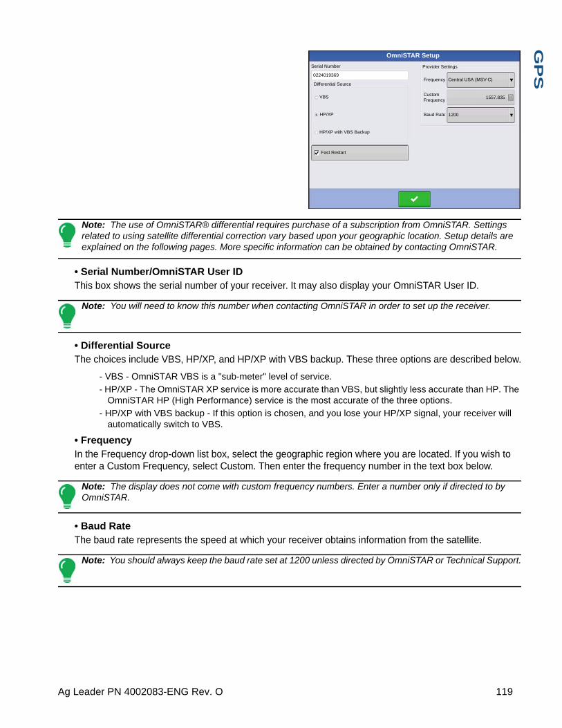
G
PS
Note: The use of OmniSTAR® differential requires purchase of a subscription from OmniSTAR. Settings related to using satellite differential correction vary based upon your geographic location. Setup details are explained on the following pages. More specific information can be obtained by contacting OmniSTAR.
• Serial Number/OmniSTAR User IDThis box shows the serial number of your receiver. It may also display your OmniSTAR User ID.
Note: You will need to know this number when contacting OmniSTAR in order to set up the receiver.
• Differential SourceThe choices include VBS, HP/XP, and HP/XP with VBS backup. These three options are described below.
- VBS - OmniSTAR VBS is a "sub-meter" level of service.
- HP/XP - The OmniSTAR XP service is more accurate than VBS, but slightly less accurate than HP. The OmniSTAR HP (High Performance) service is the most accurate of the three options.
- HP/XP with VBS backup - If this option is chosen, and you lose your HP/XP signal, your receiver will automatically switch to VBS.
• FrequencyIn the Frequency drop-down list box, select the geographic region where you are located. If you wish to enter a Custom Frequency, select Custom. Then enter the frequency number in the text box below.
Note: The display does not come with custom frequency numbers. Enter a number only if directed to by OmniSTAR.
• Baud RateThe baud rate represents the speed at which your receiver obtains information from the satellite.
Note: You should always keep the baud rate set at 1200 unless directed by OmniSTAR or Technical Support.
OmniSTAR Setup
Serial Number
0224019369
Differential Source
VBS
HP/XP
HP/XP with VBS Backup
Fast Restart
Provider Settings
Central USA (MSV-C)Frequency
Baud Rate 1200
1557.835Custom Frequency
119 Ag Leader PN 4002083-ENG Rev. O

• AutoSeed Fast RestartChecking this box before the vehicle is shut down allows the receiver to utilize shutdown time to acquire the appropriate satellites in order to ensure a quick and efficient startup. This reduces the time taken for satellite convergence after startup, and thus increases accuracy in the field.
Note: To get the most benefit from AutoSeed technology, you should shut down the vehicle in a place where the receiver has a clear view of the sky. Do not move the vehicle before powering up again.
OMNISTAR SETTINGS — GPS 2500
Press: Home button > Setup (wrench) button > GPS button > Receiver Setup (wrench) button > General tab > OmniSTAR (Differential Source drop-down menu) > Setup (wrench) button
Note: The use of OmniSTAR® differential requires purchase of a subscription from OmniSTAR. Settings related to using satellite differential correction vary based upon your geographic location. Setup details are explained on the following pages. More specific information can be obtained by contacting OmniSTAR.
• Serial Number/OmniSTAR User IDThis box shows the serial number of your receiver. It may also display your OmniSTAR User ID.
Note: You will need to know this number when contacting OmniSTAR in order to set up the receiver.
• Differential Source- VBS - OmniSTAR VBS is a "sub-meter" level of service.
- HP/XP - The OmniSTAR XP service is more accurate than VBS, but slightly less accurate than HP. The OmniSTAR HP (High Performance) service is the most accurate of the three options.
ReceiverGeneral
Differential Source
OmniSTAR
Custom Frequency
Convergence Threshold
OmniSTAR ID
1802697
Differential Source
VBS
HP/XP
Fast Restart GGA(GLONASS)
Provider Settings
Automatic Tuning
Frequency Custom
1575.42
Baud Rate 1200
None
OmniSTAR Setup
120 Firmware Version 6.3

G
PS
• Fast RestartChecking this box before the vehicle is shut down allows the receiver to utilize shutdown time to acquire the appropriate satellites in order to ensure a quick and efficient startup. This reduces the time taken for satellite convergence after startup, and thus increases accuracy in the field.
Note: To get the most benefit from Fast Restart, you should shut down the vehicle in a place where the receiver has a clear view of the sky. Do not move the vehicle before powering up again.
• GGA (GLONASS)Checking this box allows the additional GLONASS satellites to be displayed in the GGA message.
• AutoTune Frequency check boxReceiver will automatically select the strongest frequency.
• FrequencyIn the Frequency drop-down list box, select the geographic region where you are located. If you wish to enter a Custom Frequency, select Custom. Then enter the frequency number in the text box below.
Note: The display does not come with custom frequency numbers. Enter a number only if directed to by OmniSTAR.
• Baud RateThe baud rate represents the speed at which your receiver obtains information from the satellite.
Note: You should always keep the baud rate set at 1200 unless directed by OmniSTAR or Technical Support.
• Convergence ThresholdThe receiver uses the standard deviation of the solution to determine when the OmniSTAR position has converged. The receiver will label the OmniSTAR solution as “converged” when the horizontal standard deviation reaches the Convergence Threshold setting. Relaxing the convergence threshold shortens the time before a OmniSTAR solution is reported as converged. However, it does not alter the absolute behavior of the solution.
GPS INFORMATION FOR 2500 RTK
Press: GPS (satellite) button
GPS2500
121 Ag Leader PN 4002083-ENG Rev. O

GPS Information is given for the Receiver and the Base Station
2500 RTK SETUP
Press: Home button > Setup (wrench) button > GPS button > Receiver Setup (wrench) button
• Differential SourceSelect RTK for RTK Differential Correction
• Wrench buttonPressing the Wrench button opens the screens to set the RTK radio channel. Base Station and Rover must be set to the same channel
• Ignore NMEA ChecksumCheck this to ignore intermittent GPS message errors.
• Reset to DefaultsPress the Reset to Defaults button to restore receiver settings to the factory default. This will remove all custom settings.
• Enter UnlockPress to enter feature code unlocks. Unlock codes can be purchased through AgLeader.
Press: Home button > Setup (wrench) button > GPS button > Receiver Setup (wrench) button > Differential Source Setup (wrench) button
eneral Receiver Base Station
Receiver ID:
Serial Number:Firmware Version:
e-Dif Subscription:
RTK:
GLONASS:
Active Application:Application Slot 1:
Application Slot 2:
GPS25001.2Qe4
1840159Off
On
On
RTK Rover
RTK Rover
SBAS/OmniSTAR
GPS Information
General Receiver Base Station
Latitude (N)
GPS Information
Longitude (W)
Distance to Base:
42.002612500
-93.628621120
0.0
Receiver
General
GPS 2500
Port A - Connected Port B
Differential Source
RTK
Age of Differential
60
Enter Unlock
Ignore NMEA Checksum
Reset to Defaults
Receiver
122 Firmware Version 6.3

G
PS
• RTK Radio Channel
Press button to set the RTK radio channel. Base Station and Rover must be set to the same channel.
RTK Setup
RTK Radio Channel
Channel: 46
123 Ag Leader PN 4002083-ENG Rev. O

124 Firmware Version 6.3

G
UID
AN
CE
GUIDANCE
GUIDANCE
GUIDANCE/STEERING CONTROL
SETUP
Press: Home button > Setup (wrench) button > GPS button
• Manual GuidanceSelect this to perform guidance by lightbar while manually steering the vehicle.
• OnTrac2/OnTrac2+For more information, see the OnTrac2 section.
• ParaDyme/GeoSteerFor more information, see the ParaDyme insert or GeoSteer manual.
• OnTrac3For more information, see the OnTrac3 manual.
• SteerCommandFor more information, see the SteerCommand manual.
• Operator Presence AlarmThe Operator Presence Alarm disengages guidance control if the operator does not have any interaction with the display for a specified period of time. Use the drop-down menu to specify the period of time before guidance is automatically disengaged.
• Lightbar SettingsFor more information, see “Lightbar Settings” on page 126.
• Required Differential Correction for GuidanceWhen un-checked allows guidance to operate without differential correction.
Pressing the Setup (wrench) button on the Guidance Tab opens the guidance system settings for the selected guidance system.
Note: In order to use guidance with the display, you must have a GPS receiver capable of a GPS output rate of 5 Hz or more.
uire Differential ection for Guidance
Steering
Manual Guidancetor Presence Alarm
es
TSIP
Receiver
0
GPS/Guidance Setup
Lightbar Settings
OnTrac2+ (CAN A)
OnTrac2 (CAN B)
ParaDyme/GeoSteer
OnTrac3
SteerCommand
SteerCommand
125 Ag Leader PN 4002083-ENG Rev. O

LIGHTBAR SETTINGS
SETUP
Press: Home button > Setup (wrench) button > GPS button > Lightbar Settings button
• LED SpacingEnter the distance represented by each square of the lightbar (6-72 in.).
• ModeChase - center the vehicle by followig the indicator lights.
Pull - center the vehicle by turning in the opposite direction of the indicator lights on the lightbar.
• External Lightbar LED Brightness
If applicable, press / to enter in a
number specifying the brightness of the LED lights on the optional L160 external lightbar. The number 1 is the dimmest and 10 is the brightest. Default is 5.
GUIDANCE TAB ON MAPPING TOOLBOX
Press: Map button > Guidance tab (in Mapping Toolbox)
The Guidance Tab on the Mapping Toolbox allows you to you can create a new pattern, load an existing pattern, or adjust Guidance Options and Guidance Settings.This tab changes its appearance after you create or load a pattern.
Before you create any patterns, the map screen’s Guidance Tab appears as shown.
Note: Guidance pattern will default to the one last used.
Guidance patterns can be set to widths up to 2000 ft (609 m).
Lightbar Settings
12 in
External Lightbar LED Brightness
LIghtbar Settings
Spacing
Mode
Chase
5
New Pattern
Load Pattern
Manage Patterns
Guidance
126 Firmware Version 6.3
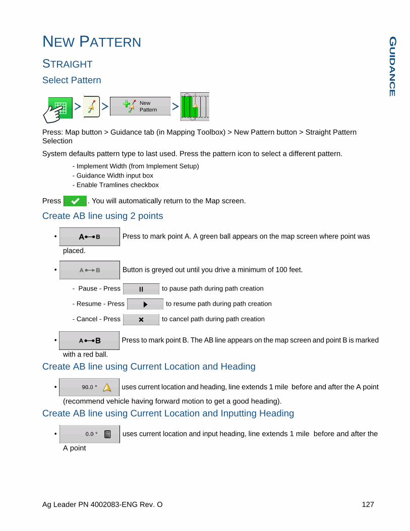
G
UID
AN
CE
NEW PATTERN
STRAIGHT
Select Pattern
Press: Map button > Guidance tab (in Mapping Toolbox) > New Pattern button > Straight Pattern Selection
System defaults pattern type to last used. Press the pattern icon to select a different pattern.
- Implement Width (from Implement Setup)
- Guidance Width input box
- Enable Tramlines checkbox
Press . You will automatically return to the Map screen.
Create AB line using 2 points
• Press to mark point A. A green ball appears on the map screen where point was
placed.
• Button is greyed out until you drive a minimum of 100 feet.
- Pause - Press to pause path during path creation
- Resume - Press to resume path during path creation
- Cancel - Press to cancel path during path creation
• Press to mark point B. The AB line appears on the map screen and point B is marked
with a red ball.
Create AB line using Current Location and Heading
• uses current location and heading, line extends 1 mile before and after the A point
(recommend vehicle having forward motion to get a good heading).
Create AB line using Current Location and Inputting Heading
• uses current location and input heading, line extends 1 mile before and after the
A point
New Pattern
127 Ag Leader PN 4002083-ENG Rev. O
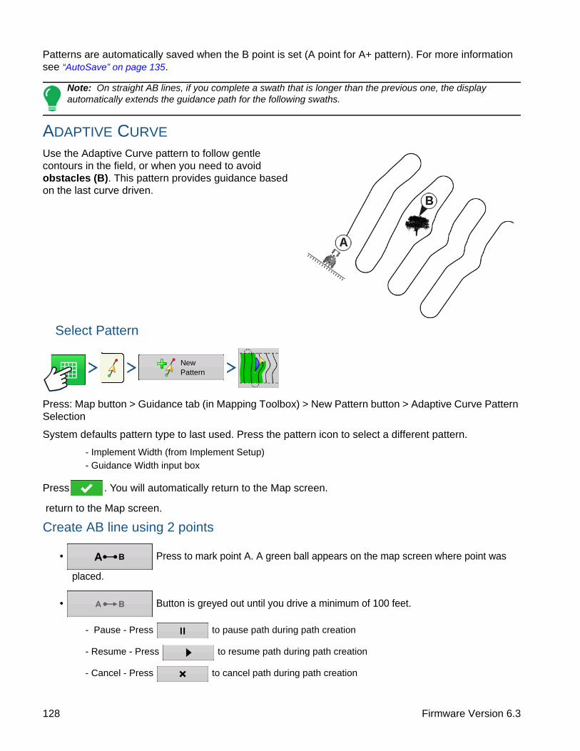
Patterns are automatically saved when the B point is set (A point for A+ pattern). For more information see “AutoSave” on page 135.
Note: On straight AB lines, if you complete a swath that is longer than the previous one, the display automatically extends the guidance path for the following swaths.
ADAPTIVE CURVE
Use the Adaptive Curve pattern to follow gentle contours in the field, or when you need to avoid obstacles (B). This pattern provides guidance based on the last curve driven.
Select Pattern
Press: Map button > Guidance tab (in Mapping Toolbox) > New Pattern button > Adaptive Curve Pattern Selection
System defaults pattern type to last used. Press the pattern icon to select a different pattern.
- Implement Width (from Implement Setup)
- Guidance Width input box
Press . You will automatically return to the Map screen.
return to the Map screen.
Create AB line using 2 points
• Press to mark point A. A green ball appears on the map screen where point was
placed.
• Button is greyed out until you drive a minimum of 100 feet.
- Pause - Press to pause path during path creation
- Resume - Press to resume path during path creation
- Cancel - Press to cancel path during path creation
New Pattern
128 Firmware Version 6.3

G
UID
AN
CE
• Press to mark point B. The AB line appears on the map screen and point B is marked
with a red ball.
Note: Guidance extends beyond the end of curved swaths. This makes it possible to get LED guidance back onto the swath if the vehicle drives past the end of a swath. The extended swath lines do not appear on screen.
Press: Map button > Guidance tab (in Mapping Toolbox) > Setup (wrench) button > Adaptive Curve tab
• You can adjust the degree heading at which the system generates the next pass by doing the following: Go to the Guidance screen and press the Options button. The Guidance Options screen appears; press the Adaptive Curve button. At the New Pass drop-down menu, select
Heading Change, then use to enter in
the degree number of your Heading Threshold.
Patterns are automatically saved when the vehicle turns for the first time. For more information see “AutoSave” on page 135.
IDENTICAL CURVE
Use the Identical Curve pattern to follow gentle contours in the field. This pattern provides guidance based on the original curve driven.
Select Pattern
Adaptive Curve
Nudge Adaptive Curve Shift Lightbar
Save
Pause
New Pass
Heading Threshold
Heading Change
100
Guidance Options
Save Group
New Pattern
129 Ag Leader PN 4002083-ENG Rev. O

Press: Map button > Guidance tab (in Mapping Toolbox) > New Pattern button > Identical Curve Pattern Selection
System defaults pattern type to last used. Press the pattern icon to select a different pattern.
- Implement Width (from Implement Setup)
- Guidance Width input box
- Enable Tramlines checkbox
Press . You will automatically return to the Map screen.
return to the Map screen.
Create AB line using 2 points
• Press to mark point A. A green ball appears on the map screen where point was
placed.
• Button is grayed out until you drive a minimum of 100 feet.
- Pause - Press to pause path during path creation
- Resume - Press to resume path during path creation
- Cancel - Press to cancel path during path creation
• Press to mark point B. The AB line appears on the map screen and point B is marked
with a red ball.
Patterns are automatically saved when the vehicle turns for the first time. For more information see “AutoSave” on page 135.
Note: Guidance extends beyond the end of curved swaths. This makes it possible to get LED guidance back onto the swath if the vehicle drives past the end of a swath. The extended swath lines do not appear on screen.
PIVOT
Use the Center-pivot pattern for a field that is irrigated using a center-pivot. With this pattern, you can drive concentric circles around the center-pivot. The display will calculate the center point based on where you have driven. Otherwise, you can enter in the latitude and longitude of the center point, if known.
130 Firmware Version 6.3
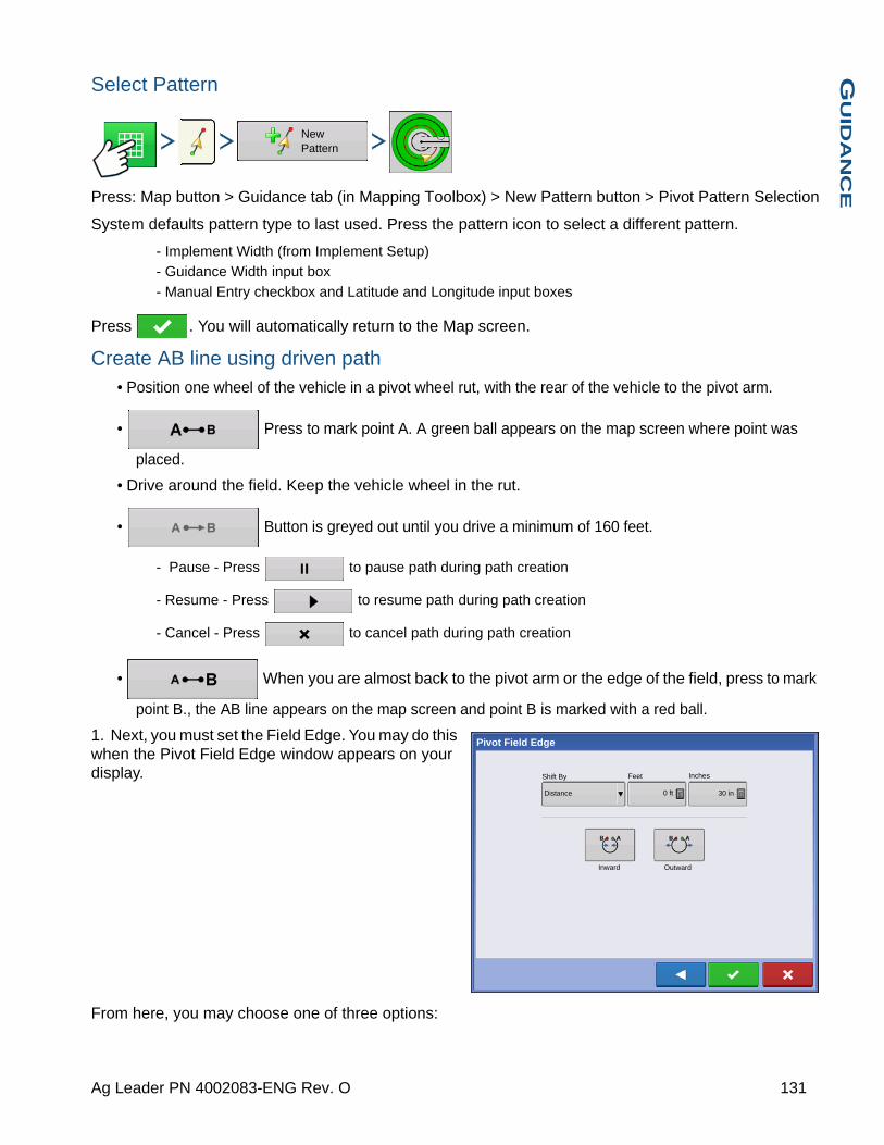
G
UID
AN
CE
Select Pattern
Press: Map button > Guidance tab (in Mapping Toolbox) > New Pattern button > Pivot Pattern Selection
System defaults pattern type to last used. Press the pattern icon to select a different pattern.
- Implement Width (from Implement Setup)
- Guidance Width input box
- Manual Entry checkbox and Latitude and Longitude input boxes
Press . You will automatically return to the Map screen.
Create AB line using driven path• Position one wheel of the vehicle in a pivot wheel rut, with the rear of the vehicle to the pivot arm.
• Press to mark point A. A green ball appears on the map screen where point was
placed.
• Drive around the field. Keep the vehicle wheel in the rut.
• Button is greyed out until you drive a minimum of 160 feet.
- Pause - Press to pause path during path creation
- Resume - Press to resume path during path creation
- Cancel - Press to cancel path during path creation
• When you are almost back to the pivot arm or the edge of the field, press to mark
point B., the AB line appears on the map screen and point B is marked with a red ball.
1. Next, you must set the Field Edge. You may do this when the Pivot Field Edge window appears on your display.
From here, you may choose one of three options:
New Pattern
Inches Shift By
Distance
Outward
Pivot Field Edge
Feet
0 ft 30 in
Inward
131 Ag Leader PN 4002083-ENG Rev. O

• Shift By DistanceThis sets the field edge as the distance and direction in relation to the AB Line created. In the Pivot Field Edge Distance portion of the window, enter the distance in feet and inches.
• Shift By RowsThis sets the field edge as the number of crop rows multiplied by the number of spacing. In the Pivot Field Edge Distance portion of the window, enter the Number of Rows and Row Spacing.
• CancelThe vehicle uses the driven pass as the AB Line.
2. If you chose Shift by Rows in the previous step, use to enter the Number of Rows and Row
Spacing. Choose the direction relative to the AB Line (either Outward or Inward), and press to continue.
3. Steer the vehicle so that you center the green lights in the lightbar as you drive forward along the path.
Note: To work from the center of the field outwards, the initial pivot must have:
• A radius of at least two swath widths.
• An arc length of at least two swath widths.
SMARTPATH
The SmartPath™ pattern is designed to give guidance from any previously-driven pass. This is used in irregular-shaped and terraced fields where you cannot run all passes parallel to the previous pass. Instead, the SmartPath guidance allows you to move to a different area of the field, and then resume a previous guidance pattern later. Moreover, you can use SmartPath to create straight AB patterns within the SmartPath pattern and cycle between any available pattern within SmartPath to choose the appropriate one.
Select SmartPath
Press: Map button > Guidance tab (in Mapping Toolbox) > New Pattern button > SmartPath Pattern Selection
System defaults pattern type to last used. Press the pattern icon to select a different pattern.
- Implement Width (from Implement Setup)
- Guidance Width input box
New Pattern
132 Firmware Version 6.3

G
UID
AN
CE
Press . You will automatically return to the Map screen.
Inputting Paths into SmartPath
AB Manager
Press: Map button > Guidance tab (in Mapping Toolbox) > A-B button > AB Manager
The AB Manager screen allow user to create, edit, remove, and load paths into SmartPath.
• Press to create an AB line.
• Press to load an AB line.
• Press to edit the name of an AB line.
• Press to delete an AB line.
You can create up to 20 different AB lines within SmartPath.
• Press the Back button to close the screen.
Cycle between Loaded Paths
Press: Map button > Guidance tab (in Mapping Toolbox) > Active Line Cyle button
Press to cycle through the paths loaded in SmartPath.
If you drive your vehicle onto the Projected Path, the system guidance uses this as the Followed Path.
Once the AB line is created, you can switch between the AB line and SmartPath patterns by pressing the AB/SmartPath toggle.
After the Guidance System has switched over to a different path, the name of the currently-followed pattern is shown within a black box on the Map screen.
The Map screen changes its appearance to Perspective View, and SmartPath settings are shown in the mapping toolbox. Drive along the path that you wish to create.
Note: The display will not create an A point with SmartPath, unless you are mapping a Straight AB line within it. (For more information, see “Once the AB line is created, you can switch between the AB line and SmartPath patterns by pressing the AB/SmartPath toggle.” on page 133).
After you turn around on your first pass, the system guidance will follow a maroon-colored line parallel to your previously-driven pass.
Load
133 Ag Leader PN 4002083-ENG Rev. O
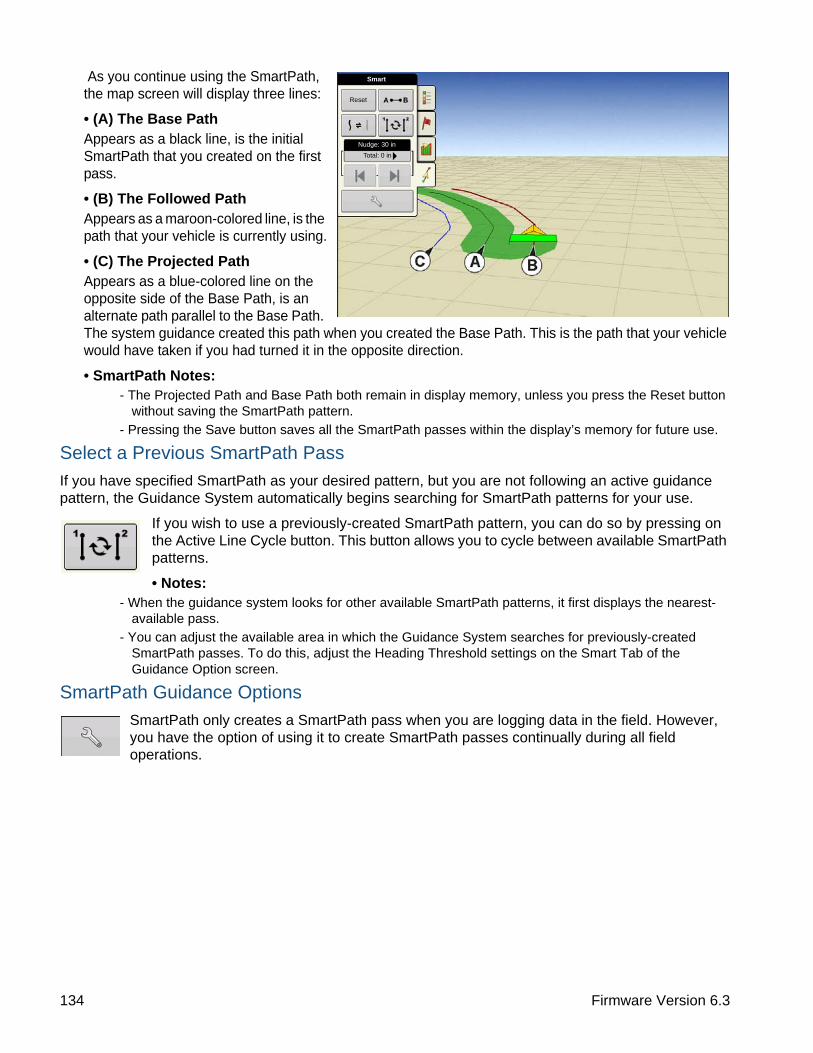
As you continue using the SmartPath, the map screen will display three lines:
• (A) The Base Path Appears as a black line, is the initial SmartPath that you created on the first pass.
• (B) The Followed PathAppears as a maroon-colored line, is the path that your vehicle is currently using.
• (C) The Projected PathAppears as a blue-colored line on the opposite side of the Base Path, is an alternate path parallel to the Base Path. The system guidance created this path when you created the Base Path. This is the path that your vehicle would have taken if you had turned it in the opposite direction.
• SmartPath Notes:- The Projected Path and Base Path both remain in display memory, unless you press the Reset button
without saving the SmartPath pattern.
- Pressing the Save button saves all the SmartPath passes within the display’s memory for future use.
Select a Previous SmartPath Pass
If you have specified SmartPath as your desired pattern, but you are not following an active guidance pattern, the Guidance System automatically begins searching for SmartPath patterns for your use.
If you wish to use a previously-created SmartPath pattern, you can do so by pressing on the Active Line Cycle button. This button allows you to cycle between available SmartPath patterns.
• Notes:- When the guidance system looks for other available SmartPath patterns, it first displays the nearest-
available pass.
- You can adjust the available area in which the Guidance System searches for previously-created SmartPath passes. To do this, adjust the Heading Threshold settings on the Smart Tab of the Guidance Option screen.
SmartPath Guidance Options
SmartPath only creates a SmartPath pass when you are logging data in the field. However, you have the option of using it to create SmartPath passes continually during all field operations.
Reset
Smart
Nudge: 30 in
Total: 0 in
134 Firmware Version 6.3

G
UID
AN
CE
To adjust this setting, press the Guidance Options button on the Guidance Tab. The Guidance Options screen appears. Press the Smart Tab.
• The default setting is Logged Area. This setting only creates passes while you are logging field data.
• By selecting All Area Covered, you can create SmartPath passes even when not logging field data.
• The Heading Threshold setting is the available area that the Guidance System uses to search for previously-created SmartPath passes. The default setting is 20 degrees.
If you chose Adaptive Curve as your pattern option at the New Pattern screen, the Adaptive Curve button appears on the Guidance Options screen. This button opens the Adaptive Pattern Options screen. At this screen, you can choose pattern options that tell the system where to log a new pass. These options include:
• New PassThis sets the conditions for the display to log a new pass. Select either Area Count or Heading Change.
- Area Count generates the next pass, based on coverage area of the previous pass. The display must be logging coverage data in order to generate the next pass.
- Heading Change logs the next pass when the vehicle turns past the heading threshold.
• Heading ThresholdEnter in the degree of turning angle that your vehicle will need to make before creating another pass.
Note: You should always set the Heading Threshold number past 90 degrees. The default number is 110 degrees.
AUTOSAVE
Patterns are automatically saved when the B point is set (A point for A+ pattern). A screen will notify user that the patterns is being saved with a default name using the date and time. Patterns can be renamed or deleted.
Nudge
Path Generation
Smart Lightbar
Save
Pause
Logged Area
Heading Threshold
All Area Covered
20
Guidance Options
degreesSave Group
0.67 ac 4.5 mph
Reset
Straight
Nudge: 30 in
Total: 0 in
Pattern saved as 2013-01-22_16:47:07
Tram: 1 R
135 Ag Leader PN 4002083-ENG Rev. O

MANAGE PATTERNS
SPATIAL SORT
Press: Map button > Guidance tab (in Mapping Toolbox) > New Pattern button
Spatial Sort allows the user to select any guidance pattern in the display, sorted by distance from the GPS location.
Pattern at the top of the list will be the closest to current GPS location.
Check the box to show all
patterns.
IMPORT PATTERN
Press: Map button > Guidance tab (in Mapping Toolbox) > Manage Patterns button > Import button >Select Pattern > Checkmark button
Display informs you when file has been successfully copied.
EXPORT PATTERN
Press: Map button > Guidance tab (in Mapping Toolbox) > Manage Patterns button > Select Pattern > Export button
Display informs you when file has been successfully copied.
EDIT PATTERN
If you wish to rename a pattern, first press the Manage Patterns button on the Guidance Tab of the
Mapping Toolbox. Press to enter a name for the pattern. The new pattern name now appears in the pattern list of the Manage Patterns screen.
New Pattern
Load Pattern
2014-01-02_
2014-01-02_
2014-01-02_
E headland
E headland 12
Slant east end
Slant east end
S side
2014-01-02_ 40.0000
40.0000
40.0000
40.0000
40.0000
40.0000
40.0000
40.0000
40.0000
01/02/2014
03/14/2012
01/02/2014
01/02/2014
01/02/2014
03/14/2012
03/14/2012
03/14/2012
03/14/2012
Straight
Straight
Straight
Curve
Curve
Straight
Straight
Straight
Straight
Show all patterns
Show all patterns
Manage Patterns
Import Select Pattern
Manage Patterns
Select Pattern Export
136 Firmware Version 6.3

G
UID
AN
CE
REMOVE PATTERN/REMOVE ALL PATTERNS
To remove a pattern from the display memory, first press the Manage Patterns button on the Guidance Tab of the Mapping Toolbox. At the Manage Patterns screen, press either:
• the Remove button if you wish to delete one pattern file; or
• the Remove All button if you wish to delete all of them for the current field.
RESET PATTERN
If you have been using an already-saved pattern, and wish to switch over to a different pattern in the same field, you can use the Reset Pattern feature by following the steps below.
1. Press ResetPress the Reset button on the Guidance screen.
2. Confirm Reset
The Guidance screen appears, asking you to reset the current guidance pattern. Press to continue.
3. Create new pattern (optional)The pattern is now reset. You may now create a new pattern, if desired.
PATTERN GROUPSPattern Groups allow the user to group up to 20 patterns per field, using the Group Manager.
The Group Manager allows the user to add a new pattern or load an existing pattern to a Group. Once a Group is created, it can be saved and reloaded.
Straight
Reset
Nudge: 2.0
Total: 0.0
Load
Group Manager
137 Ag Leader PN 4002083-ENG Rev. O
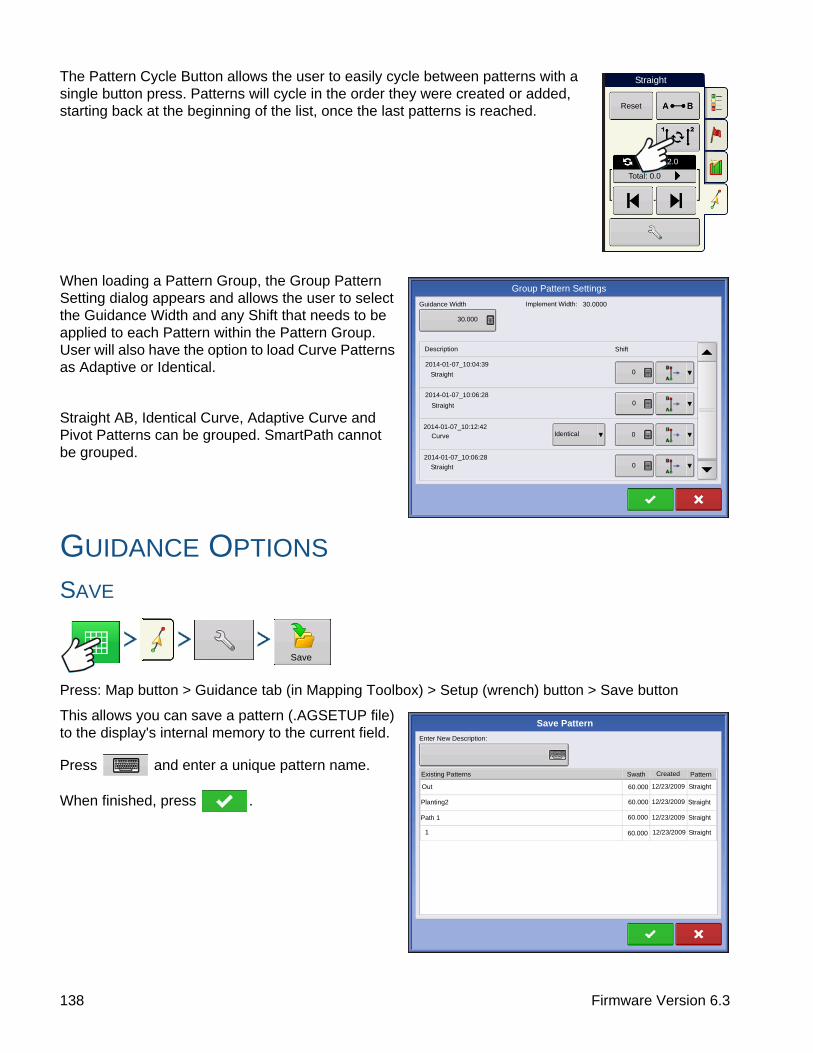
The Pattern Cycle Button allows the user to easily cycle between patterns with a single button press. Patterns will cycle in the order they were created or added, starting back at the beginning of the list, once the last patterns is reached.
When loading a Pattern Group, the Group Pattern Setting dialog appears and allows the user to select the Guidance Width and any Shift that needs to be applied to each Pattern within the Pattern Group. User will also have the option to load Curve Patterns as Adaptive or Identical.
Straight AB, Identical Curve, Adaptive Curve and Pivot Patterns can be grouped. SmartPath cannot be grouped.
GUIDANCE OPTIONS
SAVE
Press: Map button > Guidance tab (in Mapping Toolbox) > Setup (wrench) button > Save button
This allows you can save a pattern (.AGSETUP file) to the display's internal memory to the current field.
Press and enter a unique pattern name.
When finished, press .
Straight
Reset
2.0
Total: 0.0
Group Pattern Settings
Guidance Width Implement Width: 30.0000
30.000
Description Shift
2014-01-07_10:04:39
2014-01-07_10:12:42
Straight
2014-01-07_10:06:28
Curve
Straight
Identical
0
0
0
0Straight
2014-01-07_10:06:28
Save
Save Pattern
Enter New Description:
Existing Patterns Swath Created Pattern
Straight60.000
60.000
60.000
12/23/2009
12/23/2009
12/23/2009
Out
Planting2
1 60.000 12/23/2009
Straight
Straight
Straight
Path 1
138 Firmware Version 6.3
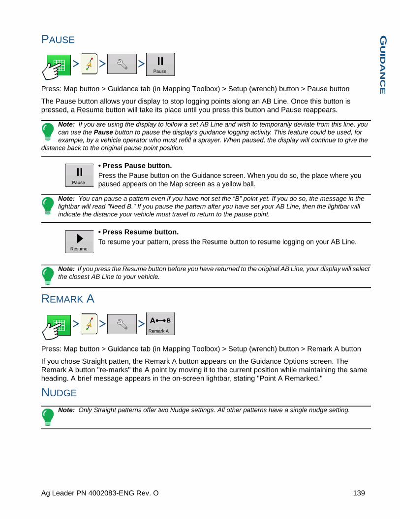
G
UID
AN
CE
PAUSE
Press: Map button > Guidance tab (in Mapping Toolbox) > Setup (wrench) button > Pause button
The Pause button allows your display to stop logging points along an AB Line. Once this button is pressed, a Resume button will take its place until you press this button and Pause reappears.
Note: If you are using the display to follow a set AB Line and wish to temporarily deviate from this line, you can use the Pause button to pause the display's guidance logging activity. This feature could be used, for example, by a vehicle operator who must refill a sprayer. When paused, the display will continue to give the
distance back to the original pause point position.
• Press Pause button.Press the Pause button on the Guidance screen. When you do so, the place where you paused appears on the Map screen as a yellow ball.
Note: You can pause a pattern even if you have not set the “B” point yet. If you do so, the message in the lightbar will read "Need B." If you pause the pattern after you have set your AB Line, then the lightbar will indicate the distance your vehicle must travel to return to the pause point.
• Press Resume button.To resume your pattern, press the Resume button to resume logging on your AB Line.
Note: If you press the Resume button before you have returned to the original AB Line, your display will select the closest AB Line to your vehicle.
REMARK A
Press: Map button > Guidance tab (in Mapping Toolbox) > Setup (wrench) button > Remark A button
If you chose Straight patten, the Remark A button appears on the Guidance Options screen. The Remark A button "re-marks" the A point by moving it to the current position while maintaining the same heading. A brief message appears in the on-screen lightbar, stating "Point A Remarked."
NUDGE
Note: Only Straight patterns offer two Nudge settings. All other patterns have a single nudge setting.
Pause
Pause
Resume
Remark A
139 Ag Leader PN 4002083-ENG Rev. O

Nudge allows you to adjust the
swaths by a specified distance.
Small Nudge (single arrow) shown on left.
Large Nudge setting (double arrow) shown on right (Straight Patterns Only).
Use Nudge toggle button to
switch between Small and Large Nudge setting.
Use Mapping Toolbox toggle button to
switch the menu between Tramline and Nudge on the Mapping Toolbox, if Tramlines are enabled.
Press: Map button > Guidance tab (in Mapping Toolbox) > Setup (wrench) button > Nudge tab
Press the Setup (wrench) button then the
Nudge tab to make adjustments to Nudge settings.
• Press to enter a distance for increment that the swaths will move with each successive press of the left or right arrows buttons on the Guidance Tab.
• To clear out the adjustment and go to the original position, press Clear Nudge.
Screen shows Small and Large increment settings for Straight path. Other Patterns will only show the small increment setting.
SHIFT
Press: Map button > Guidance tab (in Mapping Toolbox) > Setup (wrench) button > Shift tab
Reset
Nudge: 30.0 in
Total: 0.0 in
Straight
Reset
Nudge: 90.0 in
Total: 0.0 in
Straight
Nudge: 30.0 in
Total: 0.0 in
Nudge
Nudge TramlinesShift Lightbar
PauseSmall Increment:
Clear Nudge
Guidance Options
Remark A
Large Increment:
30.0 in
Total Nudge:
90.0 in
0 in
Save
Save Group
Shift
140 Firmware Version 6.3

G
UID
AN
CE
Shift moves all of the swaths by a specified distance to the left or right, (including the AB line). The swaths can be shifted by a distance or number of rows.
• Shift by Distance - enter the distance that you wish to shift the pattern. Use the Shift Left and Shift Right buttons to enter the direction and to accept change
• Shift by Rows - enter the number of rows you wish to shift the pattern. Use the Shift Left and Shift Right buttons to enter the direction and to accept change
Note: The Shift setting is not available with the SmartPath patterns.
STEERING
Press: Map button > Guidance tab (in Mapping Toolbox) > Setup (wrench) button > Steering tab
Line Acquisition — determines how aggressively the system steers onto the desired steering path. The ideal setting allows the system to take the shortest route without excessively sharp or sudden movements of the vehicle.
Steering Response — controls the oscillations of the vehicle when it is on the desired path.
Reverse Response — (ParaDyme Only) controls the oscillations of the vehicle when it is on the desired path in reverse.
Log coverage while AutoSteer is engaged checkbox
Coverage while engaged is available when an AutoSteering system (OnTrac2+, GeoSteer, ParaDyme) is connected. User can still manually control coverage logging with the on-screen coverage button. AutoSwath is unaffected by this selection.
ONTRAC TUNING
Press: Map button > Guidance tab (in Mapping Toolbox) > Setup (wrench) button > OnTrac Tuning tab
Nudge Adaptive Curve Shift Lightbar
Save
Pause
Shift Left
Guidance Options
Save Group
0
FeetShift By Inches
0Distance
Shift Right
Remark A
Steering
Nudge TramlinesShift Lightbar
Guidance Options
Line Acquisition
Steering
Steering Responce
Reverse Responce
Log coverage while Autosteer is engaged
10 10 10
Save
Pause
Save Group
Remark A
OnTrac Tuning
141 Ag Leader PN 4002083-ENG Rev. O

Motor Aggressiveness — determines how aggressively the motor engages.
Heading Aggressiveness — determines how aggressively the system reacts to achieve the correct heading.
Cross-Track Error — adjusts how aggressively the vehicle reacts to changes in cross-track error.
LIGHTBAR
Press: Map button > Guidance tab (in Mapping Toolbox) > Setup (wrench) button > Lightbar tab
• LED SpacingEnter the distance represented by each square of the lightbar (6-72 in.).
• ModeChase - center the vehicle by following the indicator lights.
Pull - center the vehicle by turning in the opposite direction of the indicator lights on the lightbar.
• External Lightbar LED Brightness
If applicable, press / to enter in a number specifying the brightness of the LED lights on the optional L160 external lightbar. The number 1 is the dimmest and 10 is the brightest. Default is 5.
TRAMLINES
(if enabled on Straight and Identical Curve Pattern types)
Press: Map button > Guidance tab (in Mapping Toolbox) > Setup (wrench) button > Tramlines tab
Tramlines only available with Straight AB and Identical Curve Pattern Types
Nudge TramlinesShift Lightbar
Guidance Options
Steering
Motor Aggressiveness 0
0
0
OnTrac Tuning
Heading Aggressiveness
Cross-Track Error
Save
Pause
Save Group
Remark A
Lightbar
Nudge TramlinesShift Lightbar
Guidance Options
Spacing External Lightbar LED Brightness
1Mode
Chase
12 in
Save
Pause
Save Group
Remark A
Tramlines
142 Firmware Version 6.3

G
UID
AN
CE
• Paths Between Tramlines - use to enter
the number of passes between tramlines.
• Paths to Start Field - use to enter the
number of passes at the begining of the field before the first tramline.
• Guide To: - use drop-down menu to choose between Paths and Tramlines.
Adjust Tramline - move the placement of the tramline by one
pass left or right.
Use the toggle button to switch menu between Tramline and
Nudge on the Mapping Toolbox.
An audible warning is sounded to alert the operator a Tramline is reached when the vehicle is ½ a swath width away.
Tramlines are also numbered under the Pass Number. This number will flash multiple times when the Tramline is reached for a visual warning.
Nudge TramlinesShift Lightbar
Guidance Options
Paths Between Tramlines
1Paths to Start Field:
Guide To:
1
Paths
Save
Pause
Save Group
Remark A
Straight
Adjust Tramline
143 Ag Leader PN 4002083-ENG Rev. O

144 Firmware Version 6.3
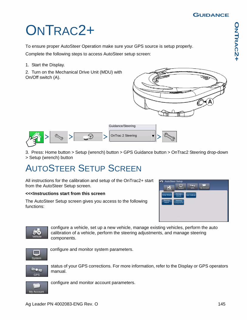
GUIDANCEO
NT
RA
C2+
GUIDANCE
ONTRAC2+To ensure proper AutoSteer Operation make sure your GPS source is setup properly.
Complete the following steps to access AutoSteer setup screen:
1. Start the Display.
2. Turn on the Mechanical Drive Unit (MDU) with On/Off switch (A).
3. Press: Home button > Setup (wrench) button > GPS Guidance button > OnTrac2 Steering drop-down > Setup (wrench) button
AUTOSTEER SETUP SCREENAll instructions for the calibration and setup of the OnTrac2+ start from the AutoSteer Setup screen.
<<<Instructions start from this screen
The AutoSteer Setup screen gives you access to the following functions:
configure a vehicle, set up a new vehicle, manage existing vehicles, perform the auto calibration of a vehicle, perform the steering adjustments, and manage steering components.
configure and monitor system parameters.
status of your GPS corrections. For more information, refer to the Display or GPS operators manual.
configure and monitor account parameters.
Guidance/Steering
OnTrac 2 Steering
My AccountGPSSystemVehicle
Setup Wizard Auto Calibrate
AutoSteer Setup
Manage Vehicle
Steering Components
Steering Adjust
Vehicle
System
GPS
My Account
145 Ag Leader PN 4002083-ENG Rev. O
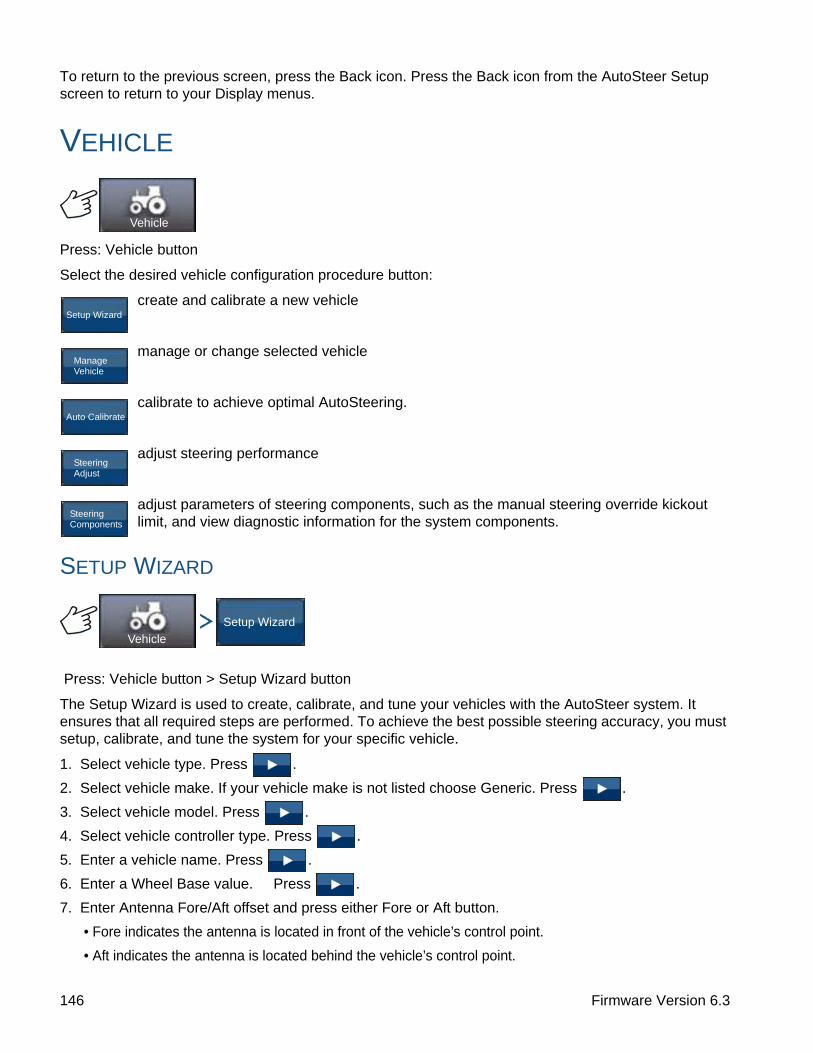
To return to the previous screen, press the Back icon. Press the Back icon from the AutoSteer Setup screen to return to your Display menus.
VEHICLE
Press: Vehicle button
Select the desired vehicle configuration procedure button:
create and calibrate a new vehicle
manage or change selected vehicle
calibrate to achieve optimal AutoSteering.
adjust steering performance
adjust parameters of steering components, such as the manual steering override kickout limit, and view diagnostic information for the system components.
SETUP WIZARD
Press: Vehicle button > Setup Wizard button
The Setup Wizard is used to create, calibrate, and tune your vehicles with the AutoSteer system. It ensures that all required steps are performed. To achieve the best possible steering accuracy, you must setup, calibrate, and tune the system for your specific vehicle.
1. Select vehicle type. Press .
2. Select vehicle make. If your vehicle make is not listed choose Generic. Press .
3. Select vehicle model. Press .
4. Select vehicle controller type. Press .
5. Enter a vehicle name. Press .
6. Enter a Wheel Base value. Press .
7. Enter Antenna Fore/Aft offset and press either Fore or Aft button.
• Fore indicates the antenna is located in front of the vehicle’s control point.
• Aft indicates the antenna is located behind the vehicle’s control point.
Vehicle
Setup Wizard
Manage Vehicle
Auto Calibrate
Steering Adjust
Steering Components
Vehicle
Setup Wizard
146 Firmware Version 6.3

GUIDANCEO
NT
RA
C2+
The Control Point of a vehicle is defined as:
• Standard Wheeled Vehicle (MFWD, Floater, Sprayer) - Rear Axle
• Track Vehicle - Center of tracks
• Articulated Tractor - Pivot point of vehicle
• Combine/Swather - Front Axle
Press .
8. Enter Antenna Lateral Offset. Select Left or Right. Press .
Note: The Antenna Lateral Offset value is tested and adjusted (if necessary) after vehicle creation and calibration is complete. Use left or right buttons to indicate if antenna is left or right of the vehicle’s center. If the antenna is perfectly centered, it does not matter which button is pressed as
long as the measurement is zero.
9. Enter Antenna Height, and then press the checkmark button.
The Wizard now takes you to the Manual Steering Override kickout limit setting procedure. When the Manual Steering Override calibration is complete, the Setup Wizard starts the Auto Calibrate procedure.
MANAGE VEHICLE
Press: Vehicle button > Manage Vehicle button
The Manage Vehicle screen enables you to:
select the active vehicle
change vehicle parameters
delete vehicle
import and export vehicle profiles
SELECT
Select Vehicle
Press: Vehicle button > Manage Vehicle button > Select Vehicle > Select button
To make a vehicle profile the Active Vehicle, select vehicle from list and press the Select button. The confirmation box will appear. Press the checkmark button and then Back icon to return to the AutoSteer Setup menu.
Vehicle
Manage Vehicle
Select
Edit
Delete
Export/ Import
Vehicle
Manage Vehicle Select
147 Ag Leader PN 4002083-ENG Rev. O

EDIT
Select Vehicle
Press: Vehicle button > Manage Vehicle button > Select Vehicle > Edit button
Select the vehicle from the list and press the Edit button. The wizard will ask for the following items:
• Wheel Base
• Antenna Fore/Aft Offset- Fore indicates the antenna is located in front of the vehicle’s control point.
- Aft indicates the antenna is located behind the vehicle’s control point.
The Control Point of a vehicle is defined as:
- Standard Wheeled Vehicle (MFWD, Floater, Sprayer) - Rear Axle
- Track Vehicle - Center of tracks
- Articulated Tractor - Pivot point of vehicle
- Combine/Swather - Front Axle
• Antenna Lateral Offset- Use left or right buttons to indicate if antenna is left or right of the vehicle’s center. If the antenna is
perfectly centered, it does not matter which button is pressed as long as the measurement is zero.
• Antenna Height
If you are satisfied with the changes, press the checkmark button. If you are not satisfied with the changes, press the X button and return to the Edit Vehicle Wizard.
DELETE
Select Vehicle
Press: Vehicle button > Manage Vehicle button > Select Vehicle > Delete button
The Delete button enables you to delete a vehicle. You can not delete the active vehicle. Select the vehicle from the list, and press the Delete button. Press the checkmark in the Delete Vehicle dialog box. Press checkmark in the confirmation box and you will return to the Manage Vehicles screen.
EXPORT/IMPORT
Select Vehicle
Press: Vehicle button > Manage Vehicle button > Select Vehicle > Export button
The Export/Import button enables you to move vehicle profiles from one AutoSteer system to another.
Note: All AutoSteer systems must be running the same version of firmware to move vehicle profiles from one system to another. For best results always upgrade all AutoSteer systems to the latest firmware version prior to importing and exporting vehicles.
Vehicle
Manage Vehicle Edit
Vehicle
Manage Vehicle
Delete
Vehicle
Manage Vehicle
Export/ Import
148 Firmware Version 6.3
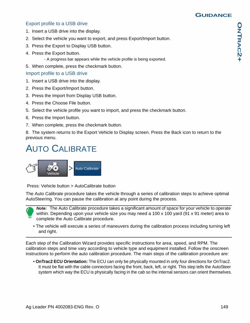
GUIDANCEO
NT
RA
C2+
Export profile to a USB drive
1. Insert a USB drive into the display.
2. Select the vehicle you want to export, and press Export/Import button.
3. Press the Export to Display USB button.
4. Press the Export button.- A progress bar appears while the vehicle profile is being exported.
5. When complete, press the checkmark button.
Import profile to a USB drive
1. Insert a USB drive into the display.
2. Press the Export/Import button.
3. Press the Import from Display USB button.
4. Press the Choose File button.
5. Select the vehicle profile you want to import, and press the checkmark button.
6. Press the Import button.
7. When complete, press the checkmark button.
8. The system returns to the Export Vehicle to Display screen. Press the Back icon to return to the previous menu.
AUTO CALIBRATE
Press: Vehicle button > AutoCalibrate button
The Auto Calibrate procedure takes the vehicle through a series of calibration steps to achieve optimal AutoSteering. You can pause the calibration at any point during the process.
Note: The Auto Calibrate procedure takes a significant amount of space for your vehicle to operate within. Depending upon your vehicle size you may need a 100 x 100 yard (91 x 91 meter) area to complete the Auto Calibrate procedure.
• The vehicle will execute a series of maneuvers during the calibration process including turning left and right.
Each step of the Calibration Wizard provides specific instructions for area, speed, and RPM. The calibration steps and time vary according to vehicle type and equipment installed. Follow the onscreen instructions to perform the auto calibration procedure. The main steps of the calibration procedure are:
• OnTrac2 ECU Orientation: The ECU can only be physically mounted in only four directions for OnTrac2. It must be flat with the cable connectors facing the front, back, left, or right. This step tells the AutoSteer system which way the ECU is physically facing in the cab so the internal sensors can orient themselves.
VehicleAuto Calibrate
149 Ag Leader PN 4002083-ENG Rev. O
• OnTrac2 ECU Tilt Zero Measurements 1 and 2: The ECU has a tilt sensor in it to help take into account side hills and bumps while the vehicle is AutoSteering. While the vehicle is sitting still on a flat location, the sensor averages its readings to get an idea of what “level” is. The driver then drives the tractor and turns it so it is facing the opposite direction at the same location and lets it average itself again. These two steps allow the system to correct any tilt differences.
• OnTrac2 Minimum Output: This step determines the minimum power needed for the MDU to turn the steering wheel. This value is critical to ensure proper AutoSteering performance.
Note: All steps of the Auto Calibrate procedure must be completed and the changes saved before any attempt is made to AutoSteer the vehicle.
• You can press Pause and Resume (or manually turn the steering wheel) at any time during the Auto Calibrate procedure if needed.
• The correct vehicle must be selected in the Manage Vehicle section prior to calibrating the vehicle. Verify that the correct vehicle has been selected.
• Your vehicle should be moving at normal operating speed before you begin the Calibration Verification process.
• The vehicle will execute a series of maneuvers during the Calibration Verification process including driving in a straight line and slight left and right turns.
• You can press Pause and Resume (or manually turn the steering wheel) at any time during the Calibration Verification procedure if needed to ensure safe vehicle operation. However, the timer for the current step is reset each time you press the Pause button.
1. Press the Auto Calibrate button.
2. Press the Right Arrow button.
3. Select the orientation that matches your installation, and then press the Next button.
4. Follow the on-screen prompts for OnTrac2 Tilt Zero Measurements 1 and 2.
5. Follow the on-screen prompts for the OnTrac2 Minimum Output screens.
6. Press the checkmark button to save the calibration data.
7. Drive the vehicle to a location where it can be driven in a straight line for a long distance. Set the speed of the vehicle within the speed range indicated, and then press the Resume button to begin the Calibration Verification process. Follow the on-screen prompts to complete the calibration.
8. When the Calibration Verification procedure is complete, press the checkmark button to return to the Vehicle screen.
9. After the vehicle has been calibrated and verified, you must confirm the accuracy of the lateral offset.
Adjust Lateral Offset
After the vehicle has been calibrated, perform the following procedure. This procedure will detect and eliminate skips and overlaps due to an incorrect lateral offset.
1. Set an AB line, engage AutoSteering, and AutoSteer for at least 50 yards (46 meters).
2. Stop your vehicle, place it in park, and turn off the AutoSteer system. Use a plumb bob to place a flag in the ground directly beneath the center of the draw bar.
3. Return to the vehicle, start the AutoSteer system, and engage AutoSteer for at least 50 yards (46 meters) on the same AB line.
4. Disengage AutoSteer, turn the vehicle around, and begin AutoSteering back down the same AB line in the opposite direction.
150 Firmware Version 6.3
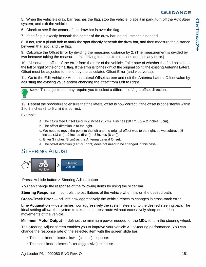
GUIDANCEO
NT
RA
C2+
5. When the vehicle's draw bar reaches the flag, stop the vehicle, place it in park, turn off the AutoSteer system, and exit the vehicle.
6. Check to see if the center of the draw bar is over the flag.
7. If the flag is exactly beneath the center of the draw bar, no adjustment is needed.
8. If not, use a plumb bob to mark the spot directly beneath the draw bar, and then measure the distance between that spot and the flag.
9. Calculate the Offset Error by dividing the measured distance by 2. (The measurement is divided by two because taking the measurements driving in opposite directions doubles any error.)
10. Observe the offset of the error from the rear of the vehicle. Take note of whether the 2nd point is to the left or right of the original flag. If the error is to the right of the original point, the existing Antenna Lateral Offset must be adjusted to the left by the calculated Offset Error (and vice versa).
11. Go to the Edit Vehicle > Antenna Lateral Offset screen and edit the Antenna Lateral Offset value by adjusting the existing value and/or changing the offset from Left to Right.
Note: This adjustment may require you to select a different left/right offset direction.
12. Repeat the procedure to ensure that the lateral offset is now correct. If the offset is consistently within 1 to 2 inches (2 to 5 cm) it is correct.
Example:
a. The calculated Offset Error is 2 inches (5 cm) [4 inches (10 cm) / 2 = 2 inches (5cm).
b. The offset direction is to the right.
c. We need to move the point to the left and the original offset was to the right, so we subtract. [5 inches (13 cm) - 2 inches (5 cm) = 3 inches (8 cm)].
d. Enter 3 inches (8 cm) as the Antenna Lateral Offset.
e. The offset direction (Left or Right) does not need to be changed in this case.
STEERING ADJUST
Press: Vehicle button > Steering Adjust button
You can change the response of the following items by using the slider bar.
Steering Response — controls the oscillations of the vehicle when it is on the desired path.
Cross-Track Error — adjusts how aggressively the vehicle reacts to changes in cross-track error.
Line Acquisition — determines how aggressively the system steers onto the desired steering path. The ideal setting allows the system to take the shortest route without excessively sharp or sudden movements of the vehicle.
Minimum Motor Output — defines the minimum power needed for the MDU to turn the steering wheel.
The Steering Adjust screen enables you to improve your vehicle AutoSteering performance. You can change the response rate of the selected item with the screen slide bar:
• The turtle icon indicates slower (smooth) response.
• The rabbit icon indicates faster (aggressive) response.
Vehicle
Steering Adjust
151 Ag Leader PN 4002083-ENG Rev. O

STEERING COMPONENTS
Press: Vehicle button > Steering Components
This screen enables you to adjust steering components. The list of components displayed varies depending on your individual installation.
OnTrac2 ECUThe OnTrac2 ECU is the box that connects the AutoSteer controller to all AutoSteer sensors and actuators. The OnTrac2 ECU screen provides indicators showing the ECU firmware version, engaged status, MDU power status, and communication status.
Manual Steering OverrideThis setting determines how much force is required to disengage AutoSteering by manually turning the steering wheel. Try the factory default limit first. If the Manual Steering Override limit is set too low, the system disengages AutoSteering under normal AutoSteering conditions. If it is set too high, the wheel requires excessive force before the system disengages.
To adjust the Manual Steering Override:
1. Press the START button and attempt to turn the steering wheel left or right with the factory default Manual Steering Override value. If the default value works satisfactorily, proceed to Step 3. If you need to set a new value, proceed to Step 2.
2. If the system does not disengage, press the minus button to lower the Manual Steering Override limit. If the system disengages too easily, press the plus button to raise the Manual Steering Override limit. Turn the steering wheel left or right with the new setting until the system disengages properly.
3. Once you are satisfied with the setting, press the Save Limit button to save the Manual Steering Override limit. The successful save dialog box appears. Press the checkmark button, and then press the Back button.
Remote Engage SwitchThe Remote Engage screen provides an indicator showing whether or not the Remote Engage Switch (if installed) is working properly. To test the Remote Engage Switch, press the remote engage switch once. The indicator light should turn green.
MDUThe MDU screen provides a diagnostic test to verify that your MDU (Mechanical Drive Unit) is operating correctly.
WARNING: Before performing this test, ensure people and objects are clear of the vehicle. When pressing the command buttons, the wheels move quickly from side to side. Press the STOP button to halt the wheels.
To test the MDU:
1. From the Steering Components screen, select MDU.
2. Read the warning carefully, and then press the Continue button.
Vehicle
Steering Components
152 Firmware Version 6.3

GUIDANCEO
NT
RA
C2+
3. Use the Steering Command buttons to send the various commands to the MDU. Observe that the steering wheel behaves according to the specified command.
Note: The command buttons control the rate at which the wheels turn left/right.
• Hard Left button — turns wheel left at 100%
• Percent Left button — turns wheels left at amount specified in slider bar
• Zero Percent button — stops wheels from turning
• Percent Right button — turns wheels right the amount specified in the slider bar
• Hard Right button — turns the wheel right at 100%
• Stop button — terminates the Steering Diagnostics procedure
• Steering Left/Right Percentage — changes turning speed (the higher percentage turning faster)
SYSTEM MENU
Press: System button
The system menu features the following functions:
monitor system parameters and performance
save, delete, or reset information in system database and log files
activate or deactivate optional sensors
password protected for use by qualified service technicians only.
upgrade system with the latest software available.
SYSTEM HEALTH
Press: System button > System Health button
The System Health screen provides diagnostic and status information for various aspects of steering system. The overview screen displays the status of the components. Select an item for which you want a detailed status.
System
System Health
Manage
Accessories
Technician
Software Upgrade
System
System Health
153 Ag Leader PN 4002083-ENG Rev. O
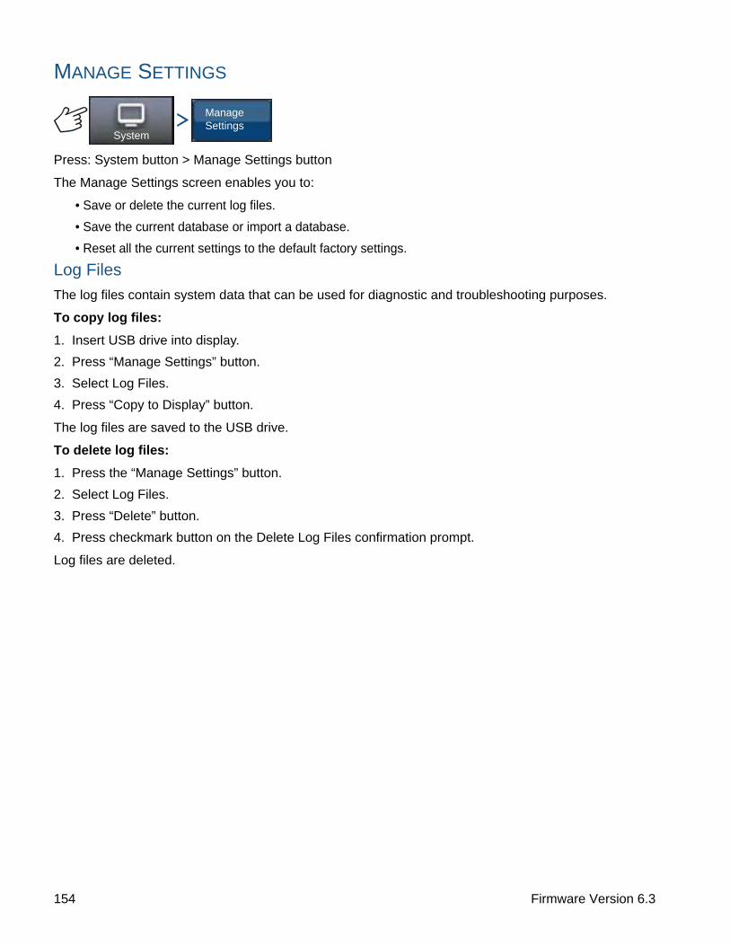
MANAGE SETTINGS
Press: System button > Manage Settings button
The Manage Settings screen enables you to:
• Save or delete the current log files.
• Save the current database or import a database.
• Reset all the current settings to the default factory settings.
Log Files
The log files contain system data that can be used for diagnostic and troubleshooting purposes.
To copy log files:
1. Insert USB drive into display.
2. Press “Manage Settings” button.
3. Select Log Files.
4. Press “Copy to Display” button.
The log files are saved to the USB drive.
To delete log files:
1. Press the “Manage Settings” button.
2. Select Log Files.
3. Press “Delete” button.
4. Press checkmark button on the Delete Log Files confirmation prompt.
Log files are deleted.
System
Manage Settings
154 Firmware Version 6.3
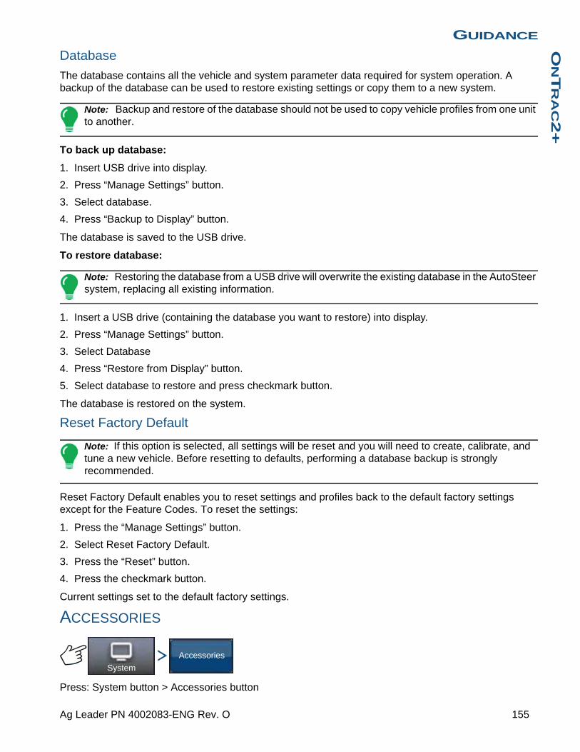
GUIDANCEO
NT
RA
C2+
Database
The database contains all the vehicle and system parameter data required for system operation. A backup of the database can be used to restore existing settings or copy them to a new system.
Note: Backup and restore of the database should not be used to copy vehicle profiles from one unit to another.
To back up database:
1. Insert USB drive into display.
2. Press “Manage Settings” button.
3. Select database.
4. Press “Backup to Display” button.
The database is saved to the USB drive.
To restore database:
Note: Restoring the database from a USB drive will overwrite the existing database in the AutoSteer system, replacing all existing information.
1. Insert a USB drive (containing the database you want to restore) into display.
2. Press “Manage Settings” button.
3. Select Database
4. Press “Restore from Display” button.
5. Select database to restore and press checkmark button.
The database is restored on the system.
Reset Factory Default
Note: If this option is selected, all settings will be reset and you will need to create, calibrate, and tune a new vehicle. Before resetting to defaults, performing a database backup is strongly recommended.
Reset Factory Default enables you to reset settings and profiles back to the default factory settings except for the Feature Codes. To reset the settings:
1. Press the “Manage Settings” button.
2. Select Reset Factory Default.
3. Press the “Reset” button.
4. Press the checkmark button.
Current settings set to the default factory settings.
ACCESSORIES
Press: System button > Accessories button
System
Accessories
155 Ag Leader PN 4002083-ENG Rev. O
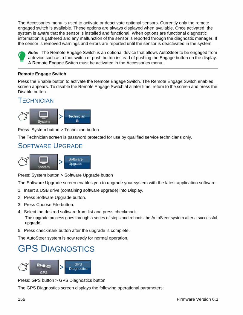
The Accessories menu is used to activate or deactivate optional sensors. Currently only the remote engaged switch is available. These options are always displayed when available. Once activated, the system is aware that the sensor is installed and functional. When options are functional diagnostic information is gathered and any malfunction of the sensor is reported through the diagnostic manager. If the sensor is removed warnings and errors are reported until the sensor is deactivated in the system.
Note: The Remote Engage Switch is an optional device that allows AutoSteer to be engaged from a device such as a foot switch or push button instead of pushing the Engage button on the display. A Remote Engage Switch must be activated in the Accessories menu.
Remote Engage Switch
Press the Enable button to activate the Remote Engage Switch. The Remote Engage Switch enabled screen appears. To disable the Remote Engage Switch at a later time, return to the screen and press the Disable button.
TECHNICIAN
Press: System button > Technician button
The Technician screen is password protected for use by qualified service technicians only.
SOFTWARE UPGRADE
Press: System button > Software Upgrade button
The Software Upgrade screen enables you to upgrade your system with the latest application software:
1. Insert a USB drive (containing software upgrade) into Display.
2. Press Software Upgrade button.
3. Press Choose File button.
4. Select the desired software from list and press checkmark.The upgrade process goes through a series of steps and reboots the AutoSteer system after a successful upgrade.
5. Press checkmark button after the upgrade is complete.
The AutoSteer system is now ready for normal operation.
GPS DIAGNOSTICS
Press: GPS button > GPS Diagnostics button
The GPS Diagnostics screen displays the following operational parameters:
System
Technician
System
Software Upgrade
GPS
GPS Diagnostics
156 Firmware Version 6.3

GUIDANCEO
NT
RA
C2+
• GPS Mode parameter — current GPS mode of the receiver.
• PDOP (Positional Dilution of Precision) — measure of the strength of the satellite configuration. When visible GPS satellites are close together in the sky, the geometry is weak and the DOP value is high; when far apart, the geometry is strong and the DOP value is low. Thus a low DOP value represents a better GPS positional accuracy.
• Heading — heading of the vehicle in degrees
• Height — vehicle’s altitude above sea level
• # of satellites — number of satellites being tracked by the receiver
• Vehicle Position — latitude and longitude of the vehicle
DETAILS
Press: My Account button > Details button
The Details button gives access to information about components installed on the system. Select the item for which you want to view details and the information about the selected item appears.
My Account
Details
157 Ag Leader PN 4002083-ENG Rev. O

158 Firmware Version 6.3

TILLAGE
TILLAGE
TILLAGE
CREATE TILLAGE CONFIGURATION
Press: Home button > Setup (wrench) button > Configuration (tractor) button > Configuration tab > Add (+) button > Tillage button
1. Select Vehicle
Use drop-down menu to choose a vehicle, or press to enter a new vehicle. Press to continue.
2. Select Implement
Select an implement from the drop-down list menu, or press to create a new implement. Press
to continue.
3. Select Speed Source
Use drop-down menu to select Primary Source, set Backup Source, and Auxiliary Channel. Press Calibrate Speed Sensor to launch the Speed Sensor Calibration Wizard.
4. Enter Configuration Name
A suggested name for the configuration appears. If desired, press to enter a different name for
your configuration. Press when complete.
Your Operating Configuration will then be viewable when you start a new Field Operation with the Field Operation Wizard.
CONFIGURATION SETUP
Press: Home button > Setup (wrench) button > Configuration (tractor) button > Configuration tab > select your specific configuration > Setup (wrench) button
Configuration Tillage
ConfigurationSelect Your Specific
Configuration
159 Ag Leader PN 4002083-ENG Rev. O

The Configuration Setup screen appears. The appearance of this screen will vary depending upon your particular operating configuration.
Depending upon your particular configuration, this process may include the following tasks:
1. Equipment SettingsAdjust Implement Switch Settings (if using an implement switch). For more information, see “Equipment Settings” on page 79.
2. Speed Input SetupFor more information, see “Speed Input Settings” on page 80.
3. Calibrate DistanceFor more information, see “Calibrate Distance” on page 81.
4. GPS OffsetsFor more information, see “Vehicle Offsets” on page 85.
5. Swath Section OffsetsFor more information, see “Swath Section Offsets” on page 86.
LOAD CONFIGURATION
Press: Select Event button.
Select a Season, Grower, Farm, and Field on the Management Selection screen.
For more information, see “Setup Event” on page 45.
RUN CONFIGURATIONOnce a configuration has been completed, the Map View button appears at the bottom of the Home screen. Press the Map View button to see the Map screen.
30 ft
Vehicle
Massey Ferguson
Massey Ferguson, Tillage
Implement: Tillage
Full Swath:
Sections: 1
Controller: None
Offsets
Configuration Setup
1
Vehicle Offsets
Speed Input
Auxiliary Input
Equipment Settings
Select Event
160 Firmware Version 6.3

TILLAGE
• (A) GPS Status
• (B) Total Field Acres
• (C) Ground Speed
• (D) Diagnostics button
• (E) Map Legend
• (F) Logging Status button
• (G) AutoSwath
• (H) Map View button
• (I) Home button
Once a configuration has been completed, the Map View button appears at the bottom of the Home screen. Press the Map View button, and the map screen appears.
Note: Pressing the Map View button will cycle between the available map screen views, and the appearance of the Map View button changes. For additional information on Map screen items, see “Run screens” on page 47.
0.11 ac 5.0 mph
No Product
Coverage
Coverage
Overlap
161 Ag Leader PN 4002083-ENG Rev. O

162 Firmware Version 6.3

PLANTINGC
RE
AT
E P
LA
NT
ING
CO
NF
IGU
RA
TIO
N
PLANTING
PLANTING
CREATE PLANTING CONFIGURATIONMost of the functionality of the display is not available until the basic setup process is completed.
You must complete these initial configuration steps for the Map screen to be active:
1. Create and Setup an Equipment Configuration
2. Product setup
3. Grower, Farm, and Field management
4. Select Event
CREATE EQUIPMENT CONFIGURATION
Press: Home button > Setup (wrench) button > Configuration (tractor) button > Configuration tab > Add (+) button > Planting button
A wizard will then guide you through the process of creating a configuration using the following steps:
1. Select Vehicle
Select an existing Vehicle from the drop-down menu, or press and create a new vehicle with the
Vehicle Setup Wizard. Press to continue.
2. Select Implement
Press to create a new implement.
3. Select Implement Type
From the top drop-down menu, select the Planter/Seeder Type setting. Press to continue.
4. Enter Make and Model
Press to enter implement make and model.
5. Select Attachment TypeChoose Rear Drawbar or Rear Lift Arms from drop-down menu.
6. Enter Distance from Hitch to Application Point
Press to enter the distance from the implement hitch to the application point (from front to back).
When finished, press to continue.
7. Select Implement OptionsUnder the Planter Monitor drop-down menu, select Seed Monitor Module or KINZE Planter Monitor Module.
Configuration Planting
163 Ag Leader PN 4002083-ENG Rev. O

• Split Rows EnabledCheck this box to enable the display to log data from the planter’s Split Row units. (For split row-enabled planters, you will need to create separate implement configurations for Split Row and non-Split Row operations).
• Planter Section Clutch ControlCheck the Planter Section Clutch Control check box if you are using Row Shutoff module.
• Down ForceCheck the Down Force check box if you are using Down Force module.
8. Rate Controller
Select an existing rate controller from the drop-down menu, or press and create a new controller
with the Controller Setup Wizard. Press to continue.
Controller Wizard:
Select Device: Seed Command
Select Device Type:
- Hydraulic Controller
- Stepper Controller
- Granular Strip Till Controller
Enter Number of drives
Enter Controller Name
9. Enter Number of Rows and Spacing.
Use / to enter the number of rows. Press and enter spacing. Press to
continue.
10. (AutoSwath Only) Number of Implement SectionsEnter the number of swath sections that can be independently turned on and off.
Note: The Clutch Module Configuration must match the actual number of row sections on the planter. Otherwise, if you try to load a Field Operation at the Field Operation Wizard, you will see a message stating that “The number of detected module outputs does not equal the number of planter sections.”
11. (AutoSwath Only) Enter Section Widths from Left to RightEnter how many rows are in each swath section from left to right screen appears. This screen shows the number of sections and number of rows in your configuration. From here you can:
- Press to continue., or
- Highlight the section number, and use to change the section row numbers; then press
to continue.
Note: The implement is divided up into equal section sizes by default. To modify the sections, press the keypad button for each section that needs to be changed.
12. Add Liquid or Granular Application
13. Enter Implement Name
Press to enter an Implement Name, Press to complete Implement Wizard.
164 Firmware Version 6.3
PLANTINGC
RE
AT
E P
LA
NT
ING
CO
NF
IGU
RA
TIO
N
You will now be returned to the Operation Configuration Wizard.
14. Select ImplementSelect Implement from drop-down menu.
15. Select Planting Method
16. Select Speed SourceUse drop-down menu to select Primary Source, set Backup Source, and configure Auxiliary Channel. Press Calibrate Speed Sensor to launch the Speed Sensor Calibration Wizard.
17. Enter Configuration Name
A suggested name for the configuration appears. If desired, Press to enter a different name for
your configuration. Press when complete.
The complete configuration should now appear on the Configuration Setup screen and is now able to be selected when starting a new Field Operation.
Note: After completing this configuration, in order for it to become active, you must adjust Seed Monitor settings in Seed Monitor Setup.
165 Ag Leader PN 4002083-ENG Rev. O

166 Firmware Version 6.3

PLANTINGA
UT
OS
WA
TH
PLANTING
AUTOSWATH
ROW SHUTOFFCreate an Implement configuration with Row Shutoff by following the procedure in “Create Planting Configuration” on page 163. By configuring your display with Row Shutoff, you can start and stop seed flow and control planter sections row-by-row, allowing AutoSwath Control to automatically turn planter row units on and off based on your planting map.
See “Map Options” on page 51 for more information on using reference maps for AutoSwath.
CONFIGURATION SETUP
Once the configuration is created and it appears on the Configuration Setup screen, AutoSwath should be configured correctly. However, if you cannot get the configuration to load on the Field Operation Wizard, or if your vehicle does not appear on the Map screen, you may wish to check if the row clutches have been correctly set up in Implement Setup. Use the following procedure to enable Seed Row Shutoff and/or configure the Clutch Module.
Press: Home button > Setup (wrench) button > Configuration (tractor) button > Configuration tab > your specific configuration > Setup (wrench) button > Row Shutoff button
The Row Shutoff Module Configuration screen appears. This screen shows the number of Row Shutoff Modules and the sections that each module controls.
ROW SHUTOFF LOOK-AHEAD NUMBERS
This table references the Turn-On Look-Ahead and Turn-Off Look-Ahead numbers for both Electric Clutch and Air Row Shutoff Modules.
Note: Using the above settings should produce good field results. However, always take the time to check for proper seed placement in the field and make system setting adjustments as needed. Do not rely solely upon the appearance of the On-Screen map. The on screen map will not show gaps and overlaps caused by
incorrect GPS Offsets or AutoSwath Look-Ahead settings.
Planter Unit Seed Meter Type On/Off Electric Clutch Air Clutch
Finger UnitsTurn On 0.9 1.1
Turn Off 0.3 0.3
VacuumTurn On 0.9 1.1
Turn Off 0.4 0.4
ConfigurationSelect Your Specific
Configuration
Row Shutoff
167 Ag Leader PN 4002083-ENG Rev. O

AUTOMATIC AUTOSWATH CONTROL
Press: Home button > Setup (wrench) button > Configuration (tractor) button > Configuration tab > select your specific configuration > Setup (wrench) button > Automatic Swath Control button
The Automatic Swath Control feature turns sections off and on automatically based upon the following conditions:
• Entering and exiting internal and outer field boundaries.
• Entering and exiting previously-applied areas within a field.
• Outside Boundary OptionSelect one of the two options to determine system behavior when a section exits a field boundary.
• Coverage OptionIn the Coverage Option area, you must choose between three options:
- The Minimize Skip option turns off the implement section after the entire section is fully inside your coverage area. This prevents the possibility of skips.
- The Minimize Overlap option turns off the implement section when that section first enters your coverage area. This prevents the possibility of overlaps.
- The User Defined option allows you to choose what percentage of the implement section is within the coverage area before that section turns off. For example, if you choose 50%, then the section will switch off when half of it is within your coverage area.
Look-Ahead Settings
AutoSwath Control settings are saved per controller per configuration. There can be different look-ahead settings saved for equipment of the same operation. The Look-Ahead Settings screen will contain every controller’s look-aheads.
On the AutoSwath Control screen, press the Look-Ahead button.
ConfigurationSelect Your Specific
Configuration
Automatic Swath Control
Automatic Swath Control
Look-Ahead Settings
100 %User Defined
Minimize Overlap
Minimize Skip
Coverage Option
Planting
Outside Boundary Option
Keep Unchanged
Turn Section Off
168 Firmware Version 6.3

PLANTINGA
UT
OS
WA
TH
• Turn-OnThis setting determines how far ahead the system looks to turn the sections back on. This setting compensates for delay in the planting control system when the implement sections are turned on.
• Turn-OffThis setting determines how far ahead the system looks to turn the sections off. This setting compensates for delay in the product control system when the sections are turned off.
Note: To use AutoSwath for planting operations, you are required to use a 5 Hz or higher GPS output rate. AutoSwath control will not allow sections to be turned on until the master and planting section switches are on. If you have less than a 5 Hz GPS output rate and you select AutoSwath, a warning appears, telling you
that AutoSwath Control is not available at less than 5 Hz.
CHECKING AUTOSWATH PERFORMANCE FOR ROW SHUTOFF
The settings given in the above AutoSwath look-ahead table shown previously have been tested with each clutch and seed meter combination to work for your planter. However, always take the time to check for proper seed placement in the field and make system setting adjustments as needed. Do not rely solely upon the appearance of the On-Screen map. The on screen map will not show gaps and overlaps caused by incorrect GPS Offsets or AutoSwath Look-Ahead settings. Verify settings with the following procedure:
1. Stop the planter within 20 feet of the planted headland.
2. Select one row unit from each planter swath section to observe.
3. Remove the down pressure from the closing wheel of each selected row unit.
4. Hold the closing wheels off the ground by attaching a chain or strap from the hopper support panel to the closing wheel arm. (This prevents the closing wheels from closing the seed trench).
Securing these closing wheels up allows you to observe the planted seed in the trench so that you can observe when the AutoSwath is turned off and on during the seed application.
5. Resume planting in your normal fashion, then stop when you are 20 feet out of the headland of the next pass.
6. Stop the planter and observe the AutoSwath shutting off and turning on to see if the results are acceptable.
• If the results are correct, then return the closing wheels to their previous operational state. Close the seed trench on the observed rows and return to planting.
• If you suspect the results are incorrect, then adjust the appropriate look-ahead setting one-tenth (.1) second per trial. When making changes to the look-ahead settings, make sure to adjust these settings only one-tenth (.1) second per trial. Larger adjustments can cause unintentional large changes in the AutoSwath’s performance. When adjusting the look-ahead numbers from the suggested settings, it is recommended that you observe multiple trials to confirm the operations’ accuracy.
• If you encounter overplanting or underplanting problems, see “Fixing Overplanting and Underplanting in AutoSwath” on page 170.
Look Ahead Settings
Turn-OnPlantingPlanting Row Shutoff Turn-Off1.1 s 0.4 s
169 Ag Leader PN 4002083-ENG Rev. O
FIXING OVERPLANTING AND UNDERPLANTING IN AUTOSWATH
AutoSwath Function — Turn Off Look Ahead
Problem — Underplanting
Recommended Action — Decrease look-ahead number
Result — The AutoSwath anticipates headlands later and turns the planter off later.
Problem — Overplanting
Recommended Action — Increase look-ahead number
Result — The AutoSwath anticipates headlands sooner and turns the planter off sooner.
AutoSwath Function — Turn On Look Ahead
Problem — Underplanting
Recommended Action — Increase look-ahead number
Result — The AutoSwath anticipates headlands sooner and turns the planter on sooner.
Problem — Overplanting
Recommended Action — Decrease look-ahead number
Result — The AutoSwath anticipates headlands later and turns the planter on later.
170 Firmware Version 6.3
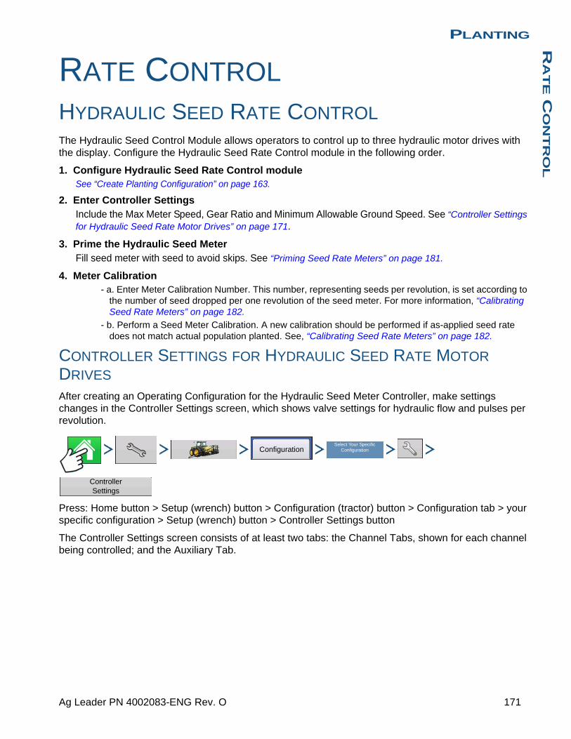
PLANTINGR
AT
E C
ON
TR
OL
PLANTING
RATE CONTROL
HYDRAULIC SEED RATE CONTROLThe Hydraulic Seed Control Module allows operators to control up to three hydraulic motor drives with the display. Configure the Hydraulic Seed Rate Control module in the following order.
1. Configure Hydraulic Seed Rate Control moduleSee “Create Planting Configuration” on page 163.
2. Enter Controller SettingsInclude the Max Meter Speed, Gear Ratio and Minimum Allowable Ground Speed. See “Controller Settings for Hydraulic Seed Rate Motor Drives” on page 171.
3. Prime the Hydraulic Seed MeterFill seed meter with seed to avoid skips. See “Priming Seed Rate Meters” on page 181.
4. Meter Calibration- a. Enter Meter Calibration Number. This number, representing seeds per revolution, is set according to
the number of seed dropped per one revolution of the seed meter. For more information, “Calibrating Seed Rate Meters” on page 182.
- b. Perform a Seed Meter Calibration. A new calibration should be performed if as-applied seed rate does not match actual population planted. See, “Calibrating Seed Rate Meters” on page 182.
CONTROLLER SETTINGS FOR HYDRAULIC SEED RATE MOTOR DRIVES
After creating an Operating Configuration for the Hydraulic Seed Meter Controller, make settings changes in the Controller Settings screen, which shows valve settings for hydraulic flow and pulses per revolution.
Press: Home button > Setup (wrench) button > Configuration (tractor) button > Configuration tab > your specific configuration > Setup (wrench) button > Controller Settings button
The Controller Settings screen consists of at least two tabs: the Channel Tabs, shown for each channel being controlled; and the Auxiliary Tab.
ConfigurationSelect Your Specific
Configuration
Controller Settings
171 Ag Leader PN 4002083-ENG Rev. O

Channel Tab settings
• Gear RatioRatio of the revolutions of the hydraulic drive as compared to one revolution of the seed meter.
• Shaft Speed CalibrationCalibration number representing the pulses that equal one revolution of the hydraulic motor.
• Maximum Meter SpeedSetting determines the maximum RPM of the seed meter.
• Allowable ErrorDetermines the percent of error that is allowed prior to the product control system making any flow rate changes.
• Control Valve SettingsThis button summons the Control Valve Settings screen. The appearance of the Control Valve Settings screen varies, depending upon whether planter’s control valves are PWM Valves or Servo Valves.
Control Valve Settings - PWM
• PWM FrequencyThe frequency at which the PWM control valve is pulsed. Settings can be found from the manufacturer of the valve.
• PWM GainDetermines how aggressively the control valve responds when making rate change adjustments. The higher the value the more aggressive the system response.
• Zero Flow OffsetRepresents the maximum duty cycle that is sent to the control valve without producing any hydraulic flow from the PWM valve. Using too high of a Zero Flow Offset value can cause the product control system to not properly control flow rates at low rates. See the PWM valve manufacturer’s information for recommended settings.
Allowable Error
Control Valve Settings
Controller Settings
Channel 1 Auxiliary
Gear Ratio
360 pls/rev
150 rpm
2 %
1.533
Shaft Speed Calibration
Maximum Meter Speed
Channel 2
Control Valve PWM
PWM Frequency
PWM Gain
Zero Flow Offset
200
130
33
Controller Valve Settings
172 Firmware Version 6.3
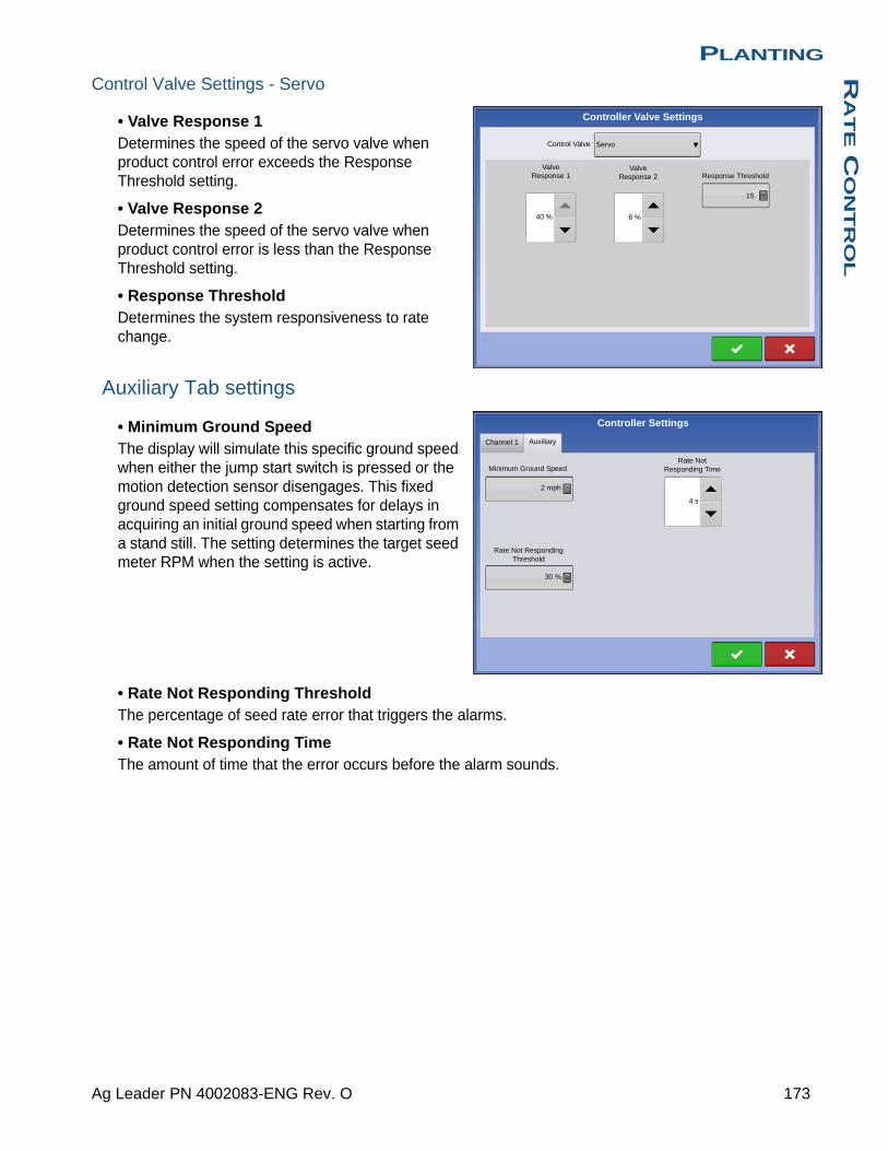
PLANTINGR
AT
E C
ON
TR
OL
Control Valve Settings - Servo
• Valve Response 1Determines the speed of the servo valve when product control error exceeds the Response Threshold setting.
• Valve Response 2Determines the speed of the servo valve when product control error is less than the Response Threshold setting.
• Response ThresholdDetermines the system responsiveness to rate change.
Auxiliary Tab settings
• Minimum Ground SpeedThe display will simulate this specific ground speed when either the jump start switch is pressed or the motion detection sensor disengages. This fixed ground speed setting compensates for delays in acquiring an initial ground speed when starting from a stand still. The setting determines the target seed meter RPM when the setting is active.
• Rate Not Responding ThresholdThe percentage of seed rate error that triggers the alarms.
• Rate Not Responding TimeThe amount of time that the error occurs before the alarm sounds.
Valve Response 1
Valve Response 2
Controller Valve Settings
Servo
40 %
Response Threshold
15
8 %
Control Valve
2 mph
Rate Not Responding Threshold
Rate Not Responding TimeMinimum Ground Speed
Channel 1 Auxiliary
30 %
4 s
Controller Settings
173 Ag Leader PN 4002083-ENG Rev. O

HYDRAULIC SEED CONTROLLER SETTINGS FOR SPECIFIC PLANTERS
Note: The settings, provided below, should be a good starting point for controller settings. However, always take the time to calibrate the seed meters, check for proper seed placement in the field, and make system setting adjustments as needed. Do not rely solely upon the appearance of the On-Screen map. The on screen
map will not show gaps and overlaps caused by incorrect GPS Offsets or AutoSwath Look-Ahead settings.
Planter brand
Con
trol
Val
ve C
onfig
urat
ion
PW
M F
requ
ency
PW
M G
ain
Zer
o F
low
Offs
et
Gea
r R
atio
Pul
ses/
Rev
.
John Deere Planters PWM 175 110 40
2.374 (chain)
2.417 (ProShaft)
360
White Planters PWM 200 90 30 5.5 360
Case IH Planters PWM 100 90 40 6.803 360
174 Firmware Version 6.3

PLANTINGR
AT
E C
ON
TR
OL
HYDRAULIC SEED METER CALIBRATION NUMBERS
Prior to calibrating the Hydraulic Seed Meter, the numbers that appear in the Meter Calibration box in the Planter Control window should be similar to the numbers that appear below. If they are not, the seed meter may be working incorrectly, or the Gear Ratio may be incorrect. Contact Technical Support for further assistance.
Note: Check the operator’s manual for more specific information on other seed disk options.
Planter brand and type Corn SoybeansCotton
Standard Rate
Sorghum
John Deere
Vacuum: Standard 30 108 64 45
Vacuum: ProMAX™ 40
Vacuum: Precision Planting eSet® 30
Vacuum: VenHuizen AccuVac Kit 40
Mechanical: Finger 12
Mechanical: Brush Meter 56
Case IH
Vacuum 48 130 80 80
Cyclo® 36 240
KINZE
EdgeVac® 39 60 54 60
Mechanical: Finger 12 60 30 60
White
30 60
Great Plains
Mechanical: Standard 12 110 120 102
Mechanical: Twin Row 6 100 135
175 Ag Leader PN 4002083-ENG Rev. O

STEPPER SEED RATE CONTROLThe Stepper Seed Control module allows Rawson ACCU-RATE Variable Rate Controller to control up to three hydraulic motor drives via the display. Configure the Stepper Seed Rate Control module in the following order.
1. Configure Stepper Seed Rate Control moduleSee “Create Planting Configuration” on page 163.
2. Enter Controller SettingsIncluded the Max Meter Speed, Gear Ratio and Minimum Allowable Ground Speed.
See “Controller Settings for Stepper Seed Rate Motor Drives” on page 176.
3. Prime the Stepper Seed MeterThis fills the seed meter with seed to avoid skips.
See “Priming Seed Rate Meters” on page 181.
4. Meter Calibration- a. Enter Meter Calibration Number. This number, representing seeds per revolution, is set according to
the number of seeds dropped per one revolution of the seed meter. See “Calibrating Seed Rate Meters” on page 182.
- b. Perform a Seed Meter Calibration. A new calibration should be performed if the as-applied seed rate does not match the actual population planted. See “Calibrating Seed Rate Meters” on page 182.
CONTROLLER SETTINGS FOR STEPPER SEED RATE MOTOR DRIVES
Stepper Controller Settings should be set before entering a meter calibration number or performing field operations.
Press: Home button > Setup (wrench) button > Configuration (tractor) button > Configuration tab > your specific configuration > Setup (wrench) button > Controller Settings button
Each channel is displayed with its own tab. Auxiliary Tab allows adjustment of the Minimum Allowable Ground Speed.
ConfigurationSelect Your Specific
Configuration
Controller Settings
176 Firmware Version 6.3
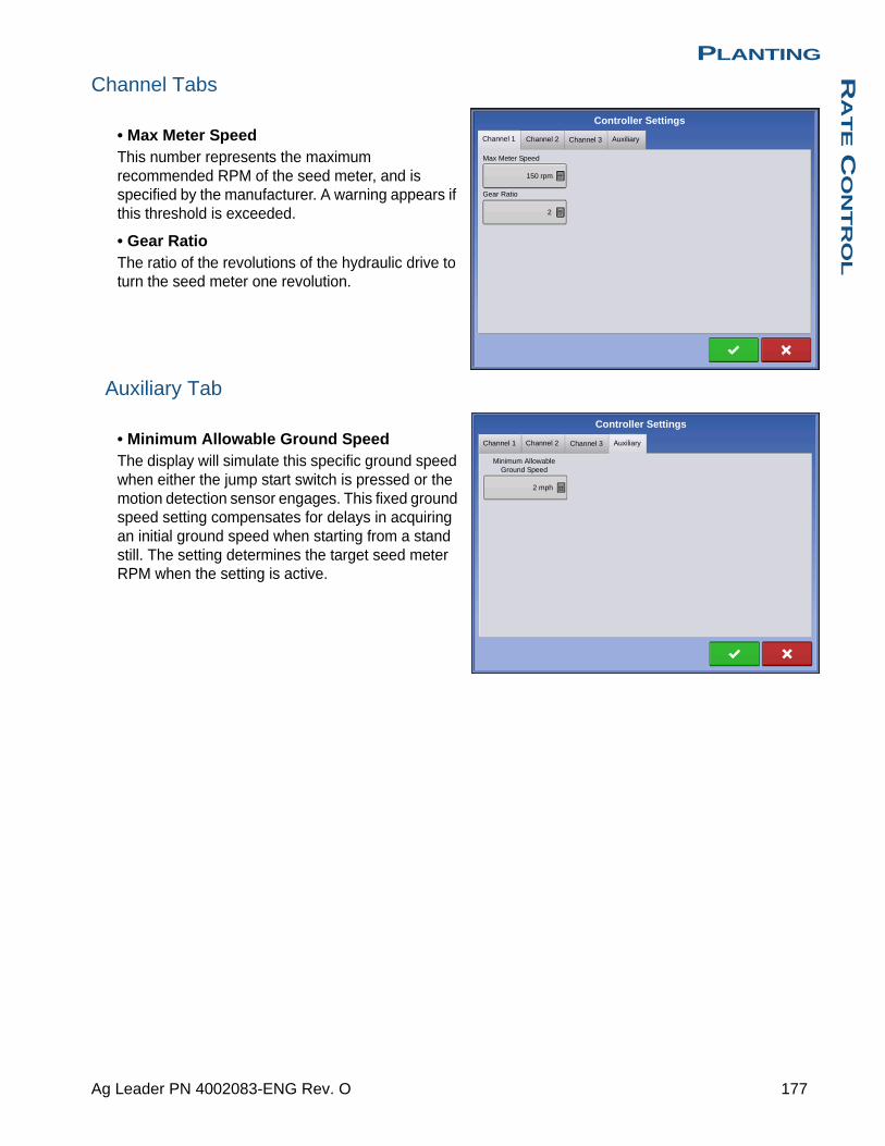
PLANTINGR
AT
E C
ON
TR
OL
Channel Tabs
• Max Meter SpeedThis number represents the maximum recommended RPM of the seed meter, and is specified by the manufacturer. A warning appears if this threshold is exceeded.
• Gear RatioThe ratio of the revolutions of the hydraulic drive to turn the seed meter one revolution.
Auxiliary Tab
• Minimum Allowable Ground SpeedThe display will simulate this specific ground speed when either the jump start switch is pressed or the motion detection sensor engages. This fixed ground speed setting compensates for delays in acquiring an initial ground speed when starting from a stand still. The setting determines the target seed meter RPM when the setting is active.
Controller Settings
Channel 1 Channel 2 Auxiliary
150 rpm
Max Meter Speed
Gear Ratio
2
Channel 3
2 mph
Controller Settings
Channel 1 Channel 2 Auxiliary
Minimum Allowable Ground Speed
Channel 3
177 Ag Leader PN 4002083-ENG Rev. O

GEAR RATIO CALCULATIONS FOR SEED RATE MOTORS
The Gear Ratio is a setting that appears on the Controller Tab for the Stepper Seed Meter Motor Drive. It is the ratio of the revolutions of the hydraulic drive as compared to one revolution of the seed meter. This setting is used to determine how fast the Stepper Seed Rate Motor should operate to achieve the proper RPM of the seed meter during planting operations.
To manually enter a Gear Ratio in the Controller Settings window, calculate the Gear Ratio based on information provided below and on the following pages. The Gear Ratio number is calculated by multiplying all the gear ratio combinations, from the Seed Rate Drive Motor to the Seed Meter.
Note: Gear Ratio number is the number of revolutions of the motor to turn the seed meter one revolution.
Gear Ratio Drawing - For Single Motor Drive
Seed Rate Drive Setting (Calculating drive gear ratio)
• (A) Seed Rate Motor (Drive) 18 Tooth Sprocket
• (B) Planter Drive Shaft Sprocket (Driven) 29 Tooth Sprocket
*Each drive combination (Driven/Drive) from Seed Rate Motor Drive to Seed Meter shaft sprocket needs to be factored for the Total Gear Ratio.
# of Teeth on the Driven Sprocket= Gear Ratio
# of Teeth on the Drive Sprocket
178 Firmware Version 6.3

PLANTINGR
AT
E C
ON
TR
OL
S(1
Gear Ratio Drawing - For Multiple Drive Combinations
Seed Rate Drive Setting (Calculating a Gear Ration for Multiple Drive Combinations)
Carry the Decimal place to the nearest 0.001 for accurate results.
Seed Ratio Calculation Example Procedure
The example outlined below assumes a single planter drive motor. Step 5 notes that this process has multiple steps for more than one Stepper Seed Motor Drives.
1. Beginning with the Seed Rate Motor, count the number of teeth on the drive sprocket. Then count the number of teeth on the driven sprocket.
2. Divide the number of teeth on the driven sprocket by the number of teeth on the drive sprocket. This is the ratio of the Seed Rate motor.
3. Repeat the process for each sprocket combination in the drive system back to the meter.
4. Take the ratio of the Seed Rate Motor and multiply it by the ratio of the other sprocket combinations.
5. Repeat this process for multiple hydraulic drives. Enter the gear ratio for each motor under the appropriate tab.
Note: Enter the number into the other channels for additional motor drives if they have the same total gear ratio.
29X
28=
812 = 2.3743
18 19 342
Driven/Drive 1 X Driven/Drive 2 = Gear Ratio
Planter Drive Sprocket X
Seed Meter Shaft = Gear Ratio
Seed Rate Motor Planter Drive Shaft
Driven/Drive 1 X Driven/Drive 2
Planter Drive Shaft Sprocket (Drive) (19 Tooth Sprocket)
Planter Drive Shaft Sprocket (Driven) (29 Tooth Sprocket)
Planter Drive Shaft Sprocket (Driven) (28 Tooth Sprocket)
DriveRatio 1
Drive Ratio 2eed Rate Motor (Drive) 8 Tooth Sprocket)
179 Ag Leader PN 4002083-ENG Rev. O

Gear Ratio Drawing Shaft Drives
Seed Rate Drive Setting.
Carry the Decimal place to the nearest 0.001 for accurate results.
If determining shaft ratios for any shaft not listed in the table above, rotate input shaft (driver) 10 times. Count how many times the output (driven) shaft turns. Divide the number of turns of the input shaft by the number of turns of the output shaft.
Table: Shaft Ratio 2
Planter Brand Driven Drive
Case IH Planters 2 2
John Deere Planters 3 2
White Planters 11 5
Note: These values are for the shaft only. Drive/Driven value between the Seed Rate Motor and Planter Drive Sprocket must still be determined.
29X
28=
812 = 2.3743
18 19 342
Driven/Drive 1 X Driven/Drive 2 = Gear Ratio
Planter Drive Sprocket X
Seed Meter Shaft = Gear Ratio
Seed Rate Motor Planter Drive Shaft
Driven/Drive 1 X Driven/Drive 2
Seed Rate Motor (Drive) (18 Tooth Sprocket)
Planter Drive Shaft Sprocket (Driven) (29 Tooth Sprocket)
Planter Drive Shaft Sprocket (Drive) (19 Tooth Sprocket)
Planter Drive Shaft Sprocket (Driven) (28 Tooth Sprocket)
Max Meter Speed
Gear Ratio
150
2.374
rpm
180 Firmware Version 6.3
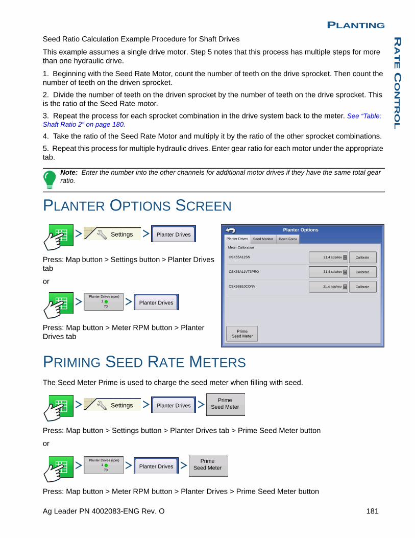
PLANTINGR
AT
E C
ON
TR
OL
Seed Ratio Calculation Example Procedure for Shaft Drives
This example assumes a single drive motor. Step 5 notes that this process has multiple steps for more than one hydraulic drive.
1. Beginning with the Seed Rate Motor, count the number of teeth on the drive sprocket. Then count the number of teeth on the driven sprocket.
2. Divide the number of teeth on the driven sprocket by the number of teeth on the drive sprocket. This is the ratio of the Seed Rate motor.
3. Repeat the process for each sprocket combination in the drive system back to the meter. See “Table: Shaft Ratio 2” on page 180.
4. Take the ratio of the Seed Rate Motor and multiply it by the ratio of the other sprocket combinations.
5. Repeat this process for multiple hydraulic drives. Enter gear ratio for each motor under the appropriate tab.
Note: Enter the number into the other channels for additional motor drives if they have the same total gear ratio.
PLANTER OPTIONS SCREEN
Press: Map button > Settings button > Planter Drives tab
or
Press: Map button > Meter RPM button > Planter Drives tab
PRIMING SEED RATE METERSThe Seed Meter Prime is used to charge the seed meter when filling with seed.
Press: Map button > Settings button > Planter Drives tab > Prime Seed Meter button
or
Press: Map button > Meter RPM button > Planter Drives > Prime Seed Meter button
Planter Drives Seed Monitor
Planter Options
31.4 sds/rev
Down Force
Meter Calibration
CSX55A12SS
CSX56A11VT3PRO
CSX56B10CONV
31.4 sds/rev
31.4 sds/rev Calibrate
Calibrate
Calibrate
Prime Seed Meter
Settings Planter Drives
Planter Drives (rpm)1
70Planter Drives
Settings Planter DrivesPrime
Seed Meter
Planter Drives (rpm)1
70Planter Drives
Prime Seed Meter
181 Ag Leader PN 4002083-ENG Rev. O
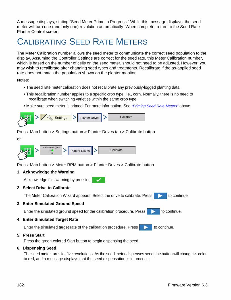
A message displays, stating “Seed Meter Prime in Progress.” While this message displays, the seed meter will turn one (and only one) revolution automatically. When complete, return to the Seed Rate Planter Control screen.
CALIBRATING SEED RATE METERSThe Meter Calibration number allows the seed meter to communicate the correct seed population to the display. Assuming the Controller Settings are correct for the seed rate, this Meter Calibration number, which is based on the number of cells on the seed meter, should not need to be adjusted. However, you may wish to recalibrate after changing seed types and treatments. Recalibrate if the as-applied seed rate does not match the population shown on the planter monitor.
Notes:
• The seed rate meter calibration does not recalibrate any previously-logged planting data.
• This recalibration number applies to a specific crop type, i.e., corn. Normally, there is no need to recalibrate when switching varieties within the same crop type.
• Make sure seed meter is primed. For more information, See “Priming Seed Rate Meters” above.
Press: Map button > Settings button > Planter Drives tab > Calibrate button
or
Press: Map button > Meter RPM button > Planter Drives > Calibrate button
1. Acknowledge the Warning
Acknowledge this warning by pressing .
2. Select Drive to Calibrate
The Meter Calibration Wizard appears. Select the drive to calibrate. Press to continue.
3. Enter Simulated Ground Speed
Enter the simulated ground speed for the calibration procedure. Press to continue.
4. Enter Simulated Target Rate
Enter the simulated target rate of the calibration procedure. Press to continue.
5. Press StartPress the green-colored Start button to begin dispensing the seed.
6. Dispensing SeedThe seed meter turns for five revolutions. As the seed meter dispenses seed, the button will change its color to red, and a message displays that the seed dispensation is in process.
Settings Planter Drives Calibrate
Planter Drives (rpm)1
70Planter Drives Calibrate
182 Firmware Version 6.3
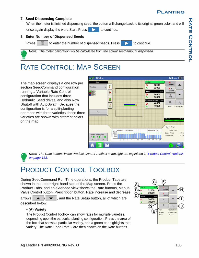
PLANTINGR
AT
E C
ON
TR
OL
7. Seed Dispensing CompleteWhen the meter is finished dispensing seed, the button will change back to its original green color, and will
once again display the word Start. Press to continue.
8. Enter Number of Dispensed Seeds
Press to enter the number of dispensed seeds. Press to continue.
Note: The meter calibration will be calculated from the actual seed amount dispensed.
RATE CONTROL: MAP SCREEN
The map screen displays a one row per section SeedCommand configuration running a Variable Rate Control configuration that includes three Hydraulic Seed drives, and also Row Shutoff with AutoSwath. Because the configuration is for a split-planting operation with three varieties, these three varieties are shown with different colors on the map.
Note: The Rate buttons in the Product Control Toolbox at top right are explained in “Product Control Toolbox” on page 183.
PRODUCT CONTROL TOOLBOX During SeedCommand Run Time operations, the Product Tabs are shown in the upper right-hand side of the Map screen. Press the Product Tabs, and an extended view shows the Rate buttons, Manual Valve Control button, Prescription button, Rate increase and decrease
arrows / , and the Rate Setup button, all of which are described below.
• (A) VarietyThe Product Control Toolbox can show rates for multiple varieties, depending upon the particular planting configuration. Press the area of the box that shows a particular variety, and a green bar highlights that variety. The Rate 1 and Rate 2 are then shown on the Rate buttons.
100%
30000
32000
38.4 ac
30000 30000
32000 32000
sds/ac
40 ft 0 in
Population: 32000 sds/ac Spacing: 6.7 in
5.0 mph
Varieties
Corn
Flow: 5280 sds/min
1
2
92B12
S46R1
sds/ac
Planter Drives (rpm)
Settings
C1966C1291
sds/ac
1 2 3
32 38 37
C1045
Down Force
Gauge Wheel: 197 lb
Down Force: 197 lb
CSX56B10CONV sds/ac
40000 40000
2 4 6 8 10 12 14 16 18 20 22 24
120 %100 %80 %60 %
30000
32000
sds/ac
sds/ac
30000 30000
30000 32000
Flow: 5280 sds/min
Applied: 501644.0 sds
Area: 19.17 ac
92B12
S46R1
183 Ag Leader PN 4002083-ENG Rev. O
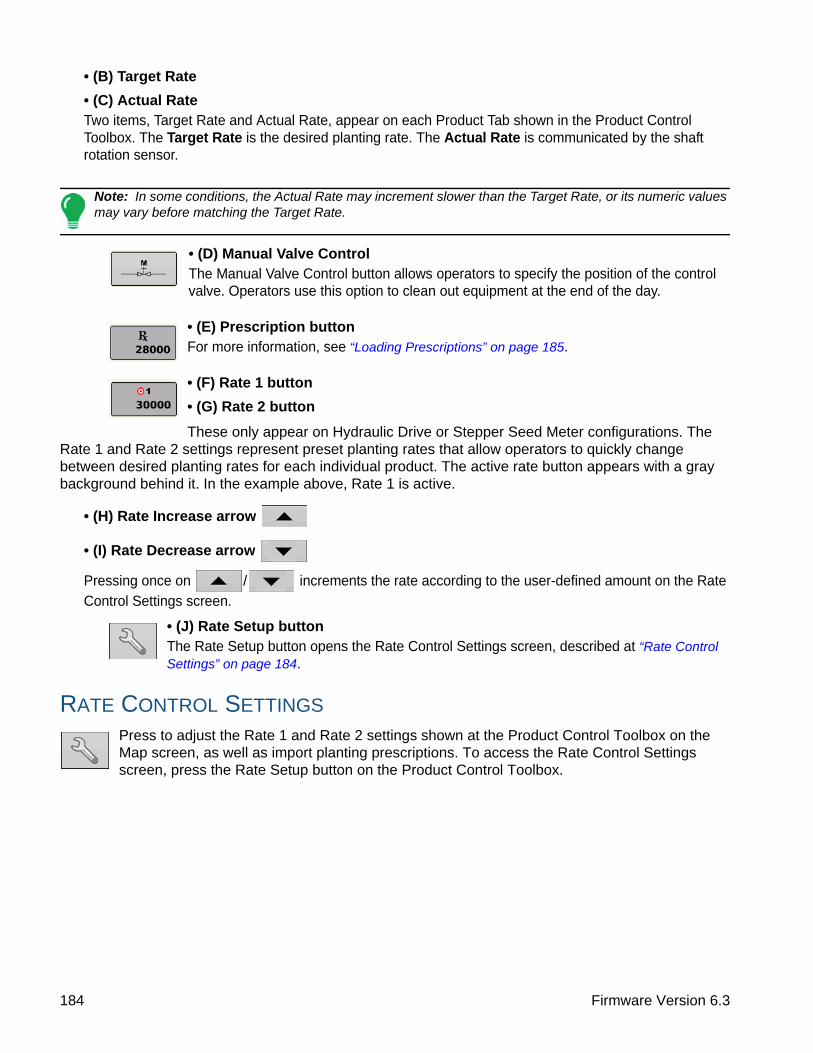
• (B) Target Rate
• (C) Actual RateTwo items, Target Rate and Actual Rate, appear on each Product Tab shown in the Product Control Toolbox. The Target Rate is the desired planting rate. The Actual Rate is communicated by the shaft rotation sensor.
Note: In some conditions, the Actual Rate may increment slower than the Target Rate, or its numeric values may vary before matching the Target Rate.
• (D) Manual Valve ControlThe Manual Valve Control button allows operators to specify the position of the control valve. Operators use this option to clean out equipment at the end of the day.
• (E) Prescription buttonFor more information, see “Loading Prescriptions” on page 185.
• (F) Rate 1 button
• (G) Rate 2 button
These only appear on Hydraulic Drive or Stepper Seed Meter configurations. The Rate 1 and Rate 2 settings represent preset planting rates that allow operators to quickly change between desired planting rates for each individual product. The active rate button appears with a gray background behind it. In the example above, Rate 1 is active.
• (H) Rate Increase arrow
• (I) Rate Decrease arrow
Pressing once on / increments the rate according to the user-defined amount on the Rate Control Settings screen.
• (J) Rate Setup buttonThe Rate Setup button opens the Rate Control Settings screen, described at “Rate Control Settings” on page 184.
RATE CONTROL SETTINGS
Press to adjust the Rate 1 and Rate 2 settings shown at the Product Control Toolbox on the Map screen, as well as import planting prescriptions. To access the Rate Control Settings screen, press the Rate Setup button on the Product Control Toolbox.
184 Firmware Version 6.3
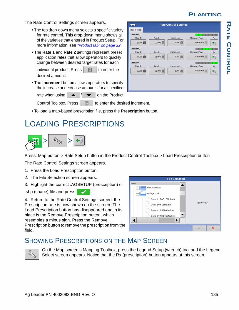
PLANTINGR
AT
E C
ON
TR
OL
The Rate Control Settings screen appears.
• The top drop-down menu selects a specific variety for rate control. This drop-down menu shows all of the varieties that entered in Product Setup. For more information, see “Product tab” on page 22.
• The Rate 1 and Rate 2 settings represent preset application rates that allow operators to quickly change between desired target rates for each
individual product. Press to enter the desired amount.
• The Increment button allows operators to specify the increase or decrease amounts for a specified
rate when using / on the Product
Control Toolbox. Press to enter the desired increment.
• To load a map-based prescription file, press the Prescription button.
LOADING PRESCRIPTIONS
Press: Map button > Rate Setup button in the Product Control Toolbox > Load Prescription button
The Rate Control Settings screen appears.
1. Press the Load Prescription button.
2. The File Selection screen appears.
3. Highlight the correct .AGSETUP (prescription) or
.shp (shape) file and press .
4. Return to the Rate Control Settings screen, the Prescription rate is now shown on the screen. The Load Prescription button has disappeared and in its place is the Remove Prescription button, which resembles a minus sign. Press the Remove Prescription button to remove the prescription from the field.
SHOWING PRESCRIPTIONS ON THE MAP SCREEN
On the Map screen’s Mapping Toolbox, press the Legend Setup (wrench) tool and the Legend Select screen appears. Notice that the Rx (prescription) button appears at this screen.
1222 (sds)
Rate 1: Rate 2: Increment: Minimum Flow
33000 32000 1000
Rate Control Settings
Rx
0 sds/min
1222 (sds)
Rate 1: Rate 2: Increment: Minimum Flow
33000 32000 1000
Rx
0 sds/min
1222 (sds)
Rate 1: Rate 2: Increment: Minimum Flow
33000 32000 1000
Rx
0 sds/min
Rate Control
irx multi product
irx single product
Demo dry DAP 175default.i
Demo dry K 0default.irx
Demo dry N 100default.irx
Demo dry NH3 0 default.irx
No Preview
Name
File Selection
185 Ag Leader PN 4002083-ENG Rev. O

1. Press the Rx button to show a legend of the prescription rate.
2. After pressing the Rx button, the prescription rate appears on the Legend. This legend is not editable.
• (A) Prescription Rate Legend
TROUBLESHOOTINGThe Troubleshooting Section consists of the following pages:
• “Fixing Overplanting and Underplanting in AutoSwath” on page 170.
• “Hydraulic Seed Control: Zero Flow Offset Variation” on page 186.
• “Stepper Seed Control Meter Alarms” on page 187.
• “Alarms on KINZE Planter Monitor” on page 219.
HYDRAULIC SEED CONTROL: ZERO FLOW OFFSET VARIATION
Zero flow offset is an operator-entered setting. Zero Flow Offset represents the maximum duty cycle that is sent to the control valve without producing any hydraulic flow from the PWM valve. Using too high of a Zero Flow Offset value can cause the product control system to not properly control low rates. Zero flow offset may vary somewhat by system and by operating conditions. On the tables on the following pages, problems and causes relating to Zero Flow Offset are listed. Use the Confirmation Techniques to determine if this is a problem; and then follow the appropriate solution.
Error Message: Drive is slow to begin turning.Possible Cause: Zero Flow Offset is set too low.
Confirmation Technique: a. Turn the Master Switch off. Enter a manual ground speed and enter a new region.
S46R1
Varieties
Rate
Rx
Clear Map LoadReferences
Legend Select
38K36K34K32K30K
Rx
Soybeans
2.74 ac 5.0 mph
S46R1 sds/ac
33000
33000
Population: 32000 sds/ac Spacing: 6.7 in
Planter Drives (rpm)
Settings
1 2 3
32 38 37
Down Force
Gauge Wheel: 197 lb
Down Force: 197 lb
2 4 6 8 10 12 14 16 18 20 22 24
120 %100 %80 %60 %80 %
186 Firmware Version 6.3

PLANTINGR
AT
E C
ON
TR
OL
b. From the Run screen, open the product application rate window, and highlight the appropriate product. Select Manual control mode.
c. Switch the Master Switch on.
d. Press the up button one time. Now press the down button one time. If the drive is not turning, the Zero Flow Offset is likely to be too low.
Solution: a. Turn the Master Switch off. Enter a manual ground speed and create a new region.
b. Increase Zero Flow Offset by 2.
c. From the Run screen, open the product application rate window, and highlight the appropriate product. Select Manual control mode.
d. Switch the Master Switch on.
e. Press the up button one time. Now press the down button one time. The drive should be turning. If not, repeat this procedure starting with Step b.
HYDRAULIC SEED CONTROL: ZERO FLOW OFFSET VARIATION
Error Message: Hydraulic drive not shutting off properly, or minimum controllable speed is greater than specified.Possible Cause: Zero Flow Offset is set too high.
Confirmation Technique: a. Turn the Master Switch off. Enter a manual ground speed and create a new region.
b. From the Run screen, open the product application rate window, and highlight the appropriate product. Select Manual control mode.
c. Switch the Master Switch on.
d. Press the up button one time. Now press the down button three times. If the drive is still turning, the zero flow offset is likely to be too high.
Solution: a. Turn the Master Switch off. Enter a manual ground speed and enter a new region.
b. Reduce Zero Flow Offset by 2.
c. From the Run screen, open the product application rate window, and highlight the appropriate product. Select Manual control mode.
d. Switch the Master Switch on.
e. Press the up button one time. Now press the down button three times. The drive should not be turning. If it is, repeat this procedure, starting with step b.
Note: Zero Flow Offset should never be less than 25. If 25 still seems as if this number is too high, there must be some other problem. Contact Technical Support for further assistance.
STEPPER SEED CONTROL METER ALARMS
Error Message: “Drive Out of Synch Error Drive #”Possible Cause: Not enough hydraulic fluid is flowing to the seed meter.
Solution: Examine the stepper seed drive’s hydraulic components for restrictions. Make sure the tractor’s hydraulic outlet is turned on. Make sure the hydraulic flow settings are correct.
Error Message: “Drive Stalled Drive #”Possible Cause: The hydraulic drive motor has stopped rotating.
Solution: Check the stepper seed motor to see if it is restricted from turning, and that the hydraulic drive is working.
187 Ag Leader PN 4002083-ENG Rev. O

Error Message: “Meter Not Moving - Drive #”Possible Cause: Either the Seed Meter Calibration failed, or the Seed Meter Prime failed
Solution: Make sure that the tractor’s hydraulic outlet is turned on.
Error Message: “Seed Drive at Maximum RPM Drive #”Possible Cause: Starting the priming routine when the hydraulic motor is not on
Solution: - Slow the planter unit’s ground speed. - Reduce the Planting Target Rate.
188 Firmware Version 6.3

PLANTINGD
OW
N F
OR
CE
PLANTING
DOWN FORCEThe gauge wheel sensors measure the weight carried by the gauge wheels. The system uses this information to adjust the down force so that the planter is firmly on the ground, to ensure correct planting depth, while trying to reduce any compaction risk.
MODES OF OPERATIONMonitor Only mode: provides the operator with information to determine if the row units are properly engaging the soil. If they are not, the operator needs to adjust the planter to correct the situation.
Control mode: as the planter travels across the field and encounters varying soil conditions (soil types, compaction zones, levels of debris) the display makes adjustments to the down force actuators on the row units, according the operator’s settings, to maintain the correct seed placement in the soil.
The system can be split between two channels to allow the down force to be adjusted separately on the planter wings and center section, where soil compaction is more likely to occur.
CREATE EQUIPMENT CONFIGURATIONCreating an Implement configuration is explained in “Create Planting Configuration” on page 163.
Press: Home button > Setup (wrench) button > Configuration (tractor) button > Configuration tab > Add (+) button > Planting button
A wizard will guide you through the process of creating a configuration using the steps shown in the planting section.
To enable Down Force, check the Down Force button on the Implement Options screen of the Wizard.
Configuration Planting
Planter Monitor
None
Split Rows Enabled
Down Force
Planter Section Clutch Control
Implement Wizard: Implement Options
189 Ag Leader PN 4002083-ENG Rev. O

At the Down Force Options screen, the operator can choose a Down Force configuration from the drop down menu:
The rows listed are the recommended rows where the sensors should be installed.
The operator can assign rows if custom installed.
Row 1 is the on the left side of the planter (when standing behind the planter facing forward).
SETUP DOWN FORCE CONFIGURATION
Press: Home button > Setup (wrench) button > Configuration (tractor) button > Configuration tab > your specific configuration > Setup (wrench) button > Down Force button
Down Force screen General tab
Down Force Mode
• Monitor Only (default)- Allows user to monitor the weight on the gauge wheels but does not adjust down pressure.
- Control Settings (Automatic Hold and Hydraulic Pressure to Down Force Conversion) are grayed out when using Monitor Only mode.
• Control- Allows user to monitor the weight on the gauge wheels and have system automatically adjust down
force.
Automatic Hold: a feature which holds down force at last know force per channel when AutoSwath turns off a section.
Down Force Configuration
2 Channel, 4 Sensor
Channel Sensor Row
1
1
1
1
2
2
2
2
1
2
3
4
1
2
3
4
2
7
18
23
11
12
13
14
Operating Configuration Wizard: Down Force Options
ConfigurationSelect Your Specific
Configuration
Down Force
Hydraulic Pressure To Down Force Conversion
Channel 2Channel 1General
Down Force Mode
Control
Control Settings
Automatic Hold
6.24 PSI/lb
Gauge Wheel Sensor
John Deere
Uplift Force
0 lb
Maximum Force
Gauge Wheel Load Alarm
448.79 lb
Minimum Load
Time Threshold
20 lb
3 s
Down Force
190 Firmware Version 6.3

PLANTINGD
OW
N F
OR
CE
Hydraulic Pressure to Down Force Conversion adjusts system to accurately display changes to hydraulic down force. This setting is row unit specific.
Force Conversions
Gauge Wheel Load Sensor is the type of gauge wheel load sensor used. This is specific to the make of your planter.
Uplift Force is usually 0 unless planter is equipped with uplift springs to provide an upward force on row units..
Maximum Force is used to limit the down force created by the actuator. The default is 425 lbs same as the factory airbag.
Gauge Wheel Load Alarm sets alarm to notify operator when system goes below Minimum Gauge Wheel Load for a set amount of time (Time Threshold).
Parallel Linkage Pressure Conversion
Deere Short Arm 4.5 psi/lb
Deere Long Arm 3.8 psi/lb
Kinze 3000 4.2 psi/lb
Kinze 4000 5.1 psi/lb
White 8000 4.8 psi/lb
Uplift Force
Parallel Linkage Uplift Force
Deere short arm 140 lbs
Deere long arm4 spring design 160 lbs
2 spring design 100 lbs
Kinze 3000 140 lbs
Kinze 4000 130 lbs
White 8000 100 lbs
191 Ag Leader PN 4002083-ENG Rev. O
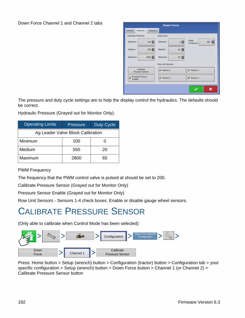
Down Force Channel 1 and Channel 2 tabs
The pressure and duty cycle settings are to help the display control the hydraulics. The defaults should be correct.
Hydraulic Pressure (Grayed out for Monitor Only).
PWM Frequency
The frequency that the PWM control valve is pulsed at should be set to 200.
Calibrate Pressure Sensor (Grayed out for Monitor Only)
Pressure Sensor Enable (Grayed out for Monitor Only)
Row Unit Sensors - Sensors 1-4 check boxes. Enable or disable gauge wheel sensors.
CALIBRATE PRESSURE SENSOR(Only able to calibrate when Control Mode has been selected)
Press: Home button > Setup (wrench) button > Configuration (tractor) button > Configuration tab > your specific configuration > Setup (wrench) button > Down Force button > Channel 1 (or Channel 2) > Calibrate Pressure Sensor button
Operating Limits Pressure Duty Cycle
Ag Leader Valve Block Calibration
Minimum 100 0
Medium 550 20
Maximum 2800 65
Down Force
Channel 1General Channel 2
Hydraulic Pressure
Minimum
Medium
Maximum
Duty Cycle
Minimum
Medium
Maximum
Row Unit Sensors
Sensor 1 Sensor 2
Sensor 3 Sensor 4
Calibrate Pressure Sensor
Pressure Sensor Enable
0
20
65
200PWM Frequency
100
550
2800
ConfigurationSelect Your Specific
Configuration
Down Force Channel 1
Calibrate Pressure Sensor
192 Firmware Version 6.3
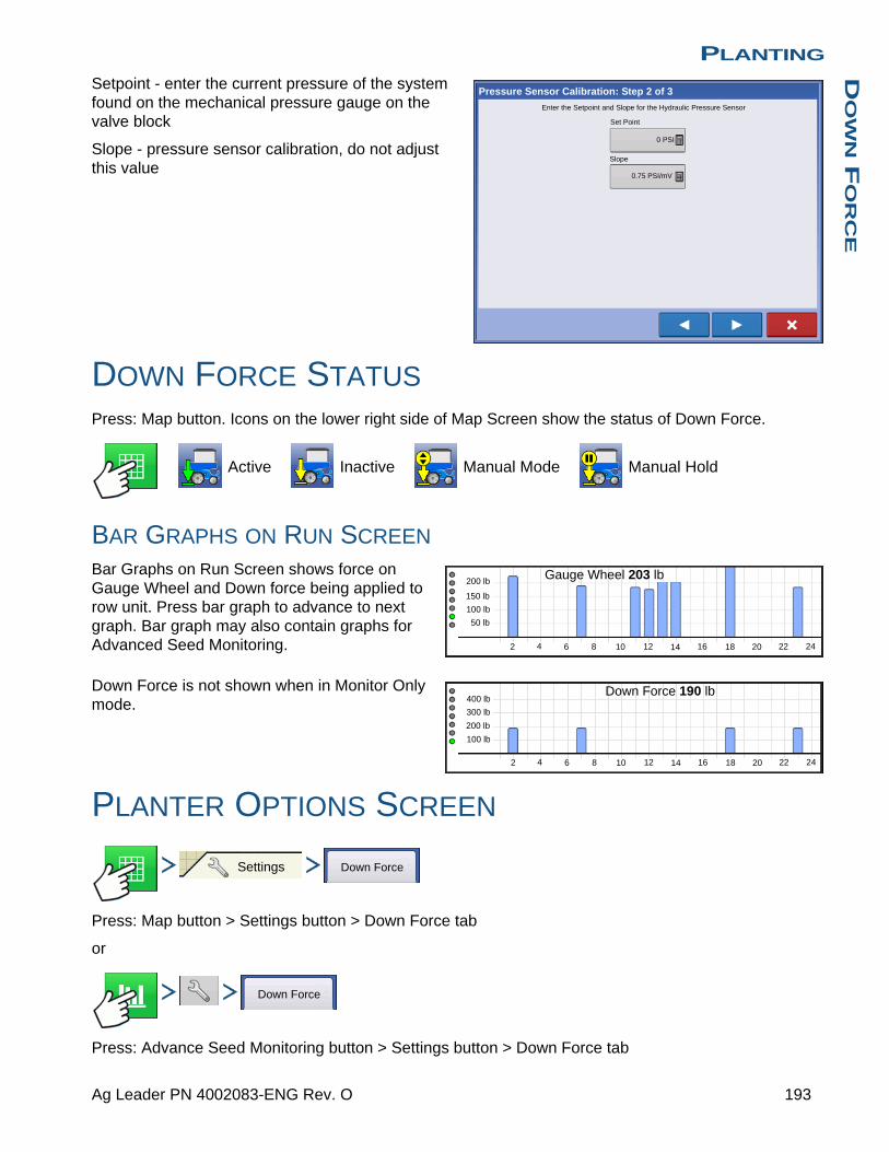
PLANTINGD
OW
N F
OR
CE
Setpoint - enter the current pressure of the system found on the mechanical pressure gauge on the valve block
Slope - pressure sensor calibration, do not adjust this value
DOWN FORCE STATUSPress: Map button. Icons on the lower right side of Map Screen show the status of Down Force.
Active Inactive Manual Mode Manual Hold
BAR GRAPHS ON RUN SCREEN
Bar Graphs on Run Screen shows force on Gauge Wheel and Down force being applied to row unit. Press bar graph to advance to next graph. Bar graph may also contain graphs for Advanced Seed Monitoring.
Down Force is not shown when in Monitor Only mode.
PLANTER OPTIONS SCREEN
Press: Map button > Settings button > Down Force tab
or
Press: Advance Seed Monitoring button > Settings button > Down Force tab
Pressure Sensor Calibration: Step 2 of 3
Set Point
0 PSI
Slope
0.75 PSI/mV
Enter the Setpoint and Slope for the Hydraulic Pressure Sensor
2 4 6 8 10 12 14 16 18 20 22 24
200 lb
150 lb
100 lb
50 lb
Gauge Wheel 203 lb
2 4 6 8 10 12 14 16 18 20 22 24
400 lb
300 lb
200 lb
100 lb
Down Force 190 lb
Settings Down Force
Down Force
193 Ag Leader PN 4002083-ENG Rev. O

Selecting Automatic Control enables
the system to control down force based on gauge wheel sensor readings.
Selecting Manual Control enables the
operator to set the downforce as they see fit.
Set offset to target gauge wheel load as calculated by the down force system.
User can select 1 of 5 available gauge wheel load settings. Each available setting is an offset to the continuously calculated target gauge wheel load. Target Gauge Wheel Load is defined as: The amount of gauge wheel load necessary to acheive proper depth 100% of the time, while minimizing compaction as much as possible (without risking loss of proper planting depth).
PLANTER PERFORMANCE SCREEN Press: Planter Performance button on the Map screen to go to the Advance Seed Monitoring screen.
Setting Offset to Target
Minimum -100 lbs
Light -50 lbs
Medium (default) 0
Heavy +50 lbs
Maximum +100 lbs
Planter Options
Planter Drives Seed Monitor
Status
Gauge Wheel
Down Force
Pressure
Active
Channel 1
Down Force
Channel 2
Active
Gauge Wheel Load
Channel 1
1 - Light
Channel 2
1 - Light
Gauge Wheel By Row
2
7
11
12
13
14
97.3 kg
86.2 kg
8.5 bar
86.2 kg
8.5 bar
102.0 kg
86.2 kg
82.9 kg
79.7 kg
93.4 kg
92.9 kg
Automatic Control
Manual Control
Automatic Control
Manual Control
Gauge Wheel Load
Channel 1
1 - Light
Channel 2
1 - Light
194 Firmware Version 6.3

PLANTINGD
OW
N F
OR
CE
Screen will show Gauge Wheel readings and Down Force across the row sections of the planter.
Down Force will not be shown when using Monitor Only
DOWN FORCE DIAGNOSTICS SCREEN
Pressing on the Device Information button, located in the upper right corner of the display, opens the Down Force Diagnostics screen. Technical support may request that you look at these screens for help in diagnosing a problem.
DOWN FORCE ALARM SCREENS
Down Force Inadequate
System hydraulic pressure is at maximum pressure
down force system does not achieve acceptable gauge wheel load
Recommendation: Planter does not weigh enough to handle the field conditions.
Gauge Wheel
Down Force
C1
Population Singulation Down Force
High26400
Low
22000
Spacing Quality -- %
Seed Spacing
Skips:
Doubles:
-- %
-- %
-- %
- %High Low Gauge Wheel:
Down Force:
--%
0.67 ac 4.5 mph
24.5 sds/ac/
200 lb
150 lb
100 lb
50 lb
400 lb
300 lb
200 lb
100 lb
8.0 in
22 lb
0 lb
26400
Row 1:
Row 1:
0 lb
0 lb
1 2 3 4 5 6 7 8 9 10 11 12 13 14 15 16 17 18 19 20 21 22 23 24
Channel Status
Sensor 1 Status
Sensor 2 Status
Sensor 3 Status
Sensor 4 Status
Hydraulic Pressure
Enabled
Enabled
Enabled
Enabled
Enabled
0.00 PSI
Channel Status
Sensor 1 Status
Sensor 2 Status
Sensor 3 Status
Sensor 4 Status
Hydraulic Pressure
Enabled
Enabled
Enabled
Enabled
Enabled
0.00 PSI
Channel 1 Channel 2
Down Force Diagnostic
Down Force
Down Force Inadequate
195 Ag Leader PN 4002083-ENG Rev. O
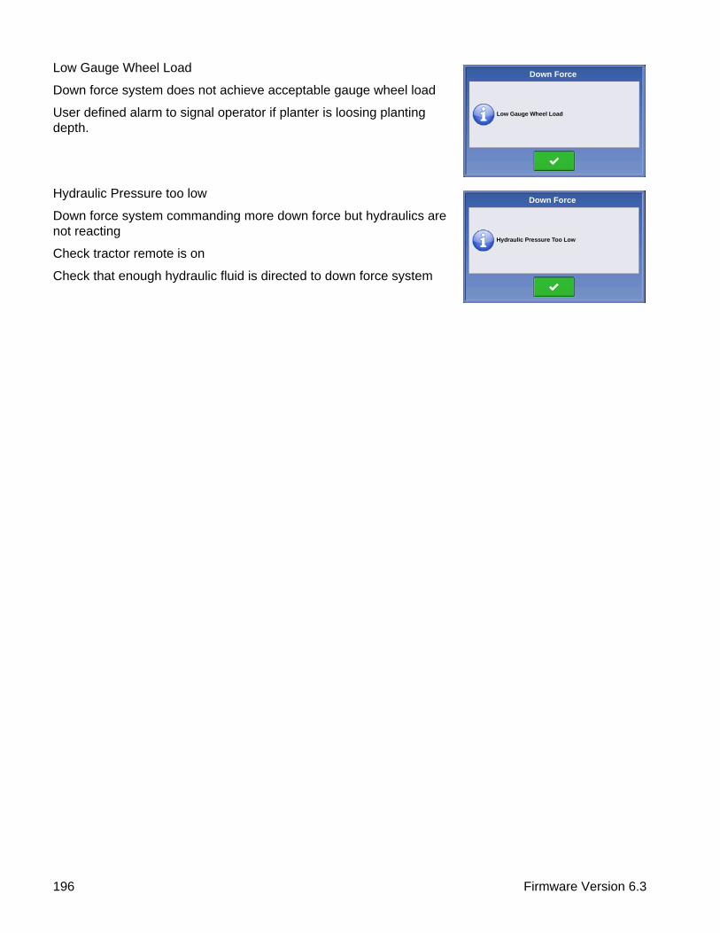
Low Gauge Wheel Load
Down force system does not achieve acceptable gauge wheel load
User defined alarm to signal operator if planter is loosing planting depth.
Hydraulic Pressure too low
Down force system commanding more down force but hydraulics are not reacting
Check tractor remote is on
Check that enough hydraulic fluid is directed to down force system
Down Force
Low Gauge Wheel Load
Down Force
Hydraulic Pressure Too Low
196 Firmware Version 6.3

PLANTINGS
EE
D T
UB
E M
ON
ITO
R M
OD
UL
E
PLANTING
SEED TUBE MONITOR MODULECONFIGURATION SETUP
Press: Home button > Setup (wrench) button > Configuration (tractor) button > Configuration tab > your specific configuration > Setup (wrench) button
Note: Use the Manage Equipment button to view a list of specific vehicles and implements.
The Configuration Setup screen appears. Screen will vary depending on the particular operating configuration. Process may include the following tasks:
1. Equipment Settings- Adjust Equipment Settings (for Rate Control).
SeedCommand configurations should adjust settings at the Equipment Configuration Settings screen. For more information, see “Equipment Settings” on page 79.
2. Speed Input SetupFor more information, see “Speed Input Settings” on page 80.
3. Calibrate DistanceFor more information, see “Calibrate Distance” on page 81.
4. AutoSwath Settings (if using AutoSwath)For more information, see “AutoSwath” on page 167.
5. GPS OffsetsAdjust GPS offsets for the Antenna Tab and the Hitch Tab. For more information, see “Vehicle Offsets” on page 85.
6. Swath Section OffsetsFor more information, see “Swath Section Offsets” on page 86.
• For information on the Auxiliary Input Settings (Switch Mapping) feature, see “Auxiliary Input” on page 82.
ConfigurationSelect Your Specific
Configuration
30 ft
GPS Offsets
Speed Input
Automatic Swath Control
Equipment Settings
Auxiliary Input
Implement Offsets
Seed Monitor
Row Shutoff
Controller Settings
Vehicle
New Holland T900New Holland T900, 12 row planter, SeedCommand
Implement: 12 row planter
Full Swath:Rows:
Sections:
12
3
Controller: SeedCommand
Serial Number:
Device:
2003810001
SeedCommand
Attachment: Rear Drawbar
1
Configuration Setup
197 Ag Leader PN 4002083-ENG Rev. O

SEED MONITOR SETUP
Press: Home button > Setup (wrench) button > Configuration (tractor) button > Configuration tab > your specific configuration > Setup (wrench) button > Seed Monitor button
• The Split Rows and Standard Rows settings show the number of rows found on the planter that the Seed Tube Monitor Module supports.
Use / to enter the total number
of rows found on the planter.
• The Speed Source shows the selected Ground Speed Source input for the Seed Tube Monitor Module. Press the Sensor to summon the Sensor Configuration window, which shows which rows are assigned to the individual pins on the Seed Tube Monitor Module.
Note: Press the Sensor to perform the AutoConfig procedure, which is necessary for a Seed Tube Monitor Module configuration to become active. Fore more information, see “AutoConfig Procedure” on page 198.
• Press the Alarms button to summon the Seed Monitor Alarms screen, which shows each row and the alarm threshold for that row. For more information, see “Seed Monitor Alarms” on page 201.
AutoConfig Procedure
The AutoConfig procedure assigns individual rows to the appropriate pins on the Seed Tube Monitor Module.
Press: Home button > Setup (wrench) button > Configuration (tractor) button > Configuration tab > your specific configuration > Setup (wrench) button > Seed Monitor button > Sensor Configuration button > AutoConfig button
ConfigurationSelect Your Specific
Configuration
Seed Monitor
Seed Monitor
Split Rows Standard Rows
0 16
Speed Source
GPS
Sensor Configuration
Alarms
Thresholds
ConfigurationSelect Your Specific
Configuration
Seed Monitor Sensor Configuration AutoConfig
198 Firmware Version 6.3

PLANTINGS
EE
D T
UB
E M
ON
ITO
R M
OD
UL
E
SEED TUBE SENSOR CONFIGURATION
Press: Home button > Setup (wrench) button > Configuration (tractor) button > Configuration tab > your specific configuration > Setup (wrench) button > Seed Monitor button > Sensor Configuration button
The Sensor Configuration screen shows which rows are assigned to the individual pins on the Seed Tube Monitor Module.
• moves the sensor to a different location, to
make configuration changes for custom planting operations.
Note: To return to the default, press the AutoConfig button.
• The Status button enables and disables a Seed Tube sensor.
Note: A row with a failed sensor can be ignored until a replacement sensor is installed.
• The AutoConfig button sends the planter settings to the Seed Tube Monitor Module.
Note: After creating a Seed Tube Monitor Module configuration, in order for it to become active, perform an AutoConfig procedure.
• The Remove button removes an individual Seed Tube sensor.
• Use the row spacing keypad to enter in the row spacing.
STMM Split-Row Configurations- If a split-row planting configuration is specified in the drop-down list shown on the Seed Monitor Setup
screen (see “Seed Monitor Setup” on page 198), then the Selection window will appear after the first time that you press the Sensor on the Seed Monitor Setup window. Choose between Standard Row or
Split Row, and press .
- Split-rows must configure the Seed Tube Monitor Module for both Standard Row configurations and Split Row Configurations. Both configurations are then saved in the display, and settings for each planting configuration are automatically applied when you specify the machine configuration at the Field Operation Configuration Wizard.
ConfigurationSelect Your Specific
Configuration
Seed Monitor Sensor Configuration
29.9 in
Sensor Configuration
1 1 Enabled
2 2 Enabled
3 3 Enabled
4 4 Enabled
5 5 Enabled
6 6 Enabled
7 7 Enabled
Row Spacing
Status
AutoConfig
Row Sensor Status
8 8 Enabled
9 9 Enabled Remove
199 Ag Leader PN 4002083-ENG Rev. O
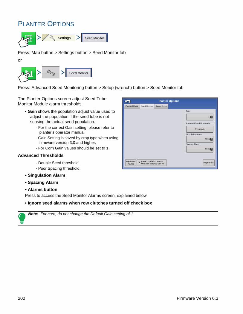
PLANTER OPTIONS
Press: Map button > Settings button > Seed Monitor tab
or
Press: Advanced Seed Monitoring button > Setup (wrench) button > Seed Monitor tab
The Planter Options screen adjust Seed Tube Monitor Module alarm thresholds.
• Gain shows the population adjust value used to adjust the population if the seed tube is not sensing the actual seed population.
- For the correct Gain setting, please refer to planter’s operator manual.
- Gain Setting is saved by crop type when using firmware version 3.0 and higher.
- For Corn Gain values should be set to 1.
Advanced Thresholds
- Double Seed threshold
- Poor Spacing threshold
• Singulation Alarm
• Spacing Alarm
• Alarms buttonPress to access the Seed Monitor Alarms screen, explained below.
• Ignore seed alarms when row clutches turned off check box
Note: For corn, do not change the Default Gain setting of 1.
Settings Seed Monitor
Seed Monitor
Planter Drives Seed Monitor
Planter Options
Singulation Alarm
Down Force
Advanced Seed Monitoring
Gain
1
Thresholds
98 %
Population Alarms
Spacing Alarm
98 %
DiagnosticsIgnore population alarms when row clutches turn off
200 Firmware Version 6.3

PLANTINGS
EE
D T
UB
E M
ON
ITO
R M
OD
UL
E
SEED MONITOR DIAGNOSTICS
Press: Map button > Settings button > Seed Monitor tab > Diagnostics button
The Seed Monitor Diagnostics screen shows row data from rows monitored by the Seed Tube Monitor Module, including the following:
• Row unit seeds per second
• Row unit seeds per acre
Note: This can also be accessed on the CAN device list under Diagnostics.
SEED MONITOR ALARMS
Press: Map button > Settings button > Seed Monitor tab > Population Alarms
Adjust Seed Tube Monitor Module alarm thresholds. This screen can be accessed in one of two ways:
- Pressing the Alarms button at the Seed Monitor Option screen.
- Pressing the Alarms button at the Seed Monitor Setup screen.
High and Low buttons assign a percentage of error that will trigger the rate alarm.
• The Disable High and Disable Low buttons deactivate the respective high or low rate alarms.
• The Select All button selects all rows to change the alarm threshold for the entire group.
Settings Seed Monitor Diagnostics
Seed Monitor Diagnostics
1 13 79040
2 13 79040
3 13 79040
4 13 79040
5 13 79040
6 13 79040
7 13 79040
8 13 79040
9 13 79040
10 13 79040
11 13 79040
12 13 79040
Seed Sensors
sds/sec sds/hasds/ha
Settings Seed MonitorPopulation
Alarms
Seed Monitor Alarms
1 70% 120%
2 70% 120%
3 70% 120%
4 70% 120%
5 70% 120%
6 70% 120%
7 70% 120%
8 70% 120%
9 70% 120%
10 70% 120%
11 70% 120%
High
Low
Disable High
Disable Low
Select All
HighLowRow
201 Ag Leader PN 4002083-ENG Rev. O

SEED MONITOR THRESHOLDS
Press: Map button > Settings button > Seed Monitor tab > Thresholds button
Adjust Seed Tube Monitor Module alarm thresholds.
SEEDCOMMAND MAP SCREEN EXAMPLES
Below is an example of a SeedCommand operating configuration. The screen shows a Seed Tube Monitor Module (STMM), with Row Shutoff and three Stepper Motor Drives.
• (A) Mapping Toolbox
• (B) Product Control Toolbox
• (C) Section IndicatorsShown at the bottom of the Product Control Toolbox.
• (D) Meter RPM buttonAppears at the bottom right hand side of the Map screen, displays the number of hydraulic or stepper seed motors and their speed, shown in Revolutions Per Minute (RPM). Pressing the Meter RPM button summons the Seed Rate Planter Control screen, to calibrate and prime the seed meters. See “Priming Seed Rate Meters” on page 181 and “Calibrating Seed Rate Meters” on page 182.
• (E) AutoSwath
The Seed Tube Monitor Module provides population monitoring for DICKEY-john® seed tube sensors used on several different brands of planters. Configure the Seed Tube Monitor Module in the following order.
Settings Seed Monitor Thresholds
5 in
3 in
Seed Monitor Thresholds
Corn
Poor Spacing Threshold
Double Seed Threshold
38.4 ac
0.67 ac
5.0 mph
29000
30000
sds/ac
30000 30000
Flow:
Applied:
Area:
7920 sds/min
19602.0 sds
1
2
Population: 32000 sds/ac Spacing: 6.7 in
Planter Drives (rpm)
Settings
1 2 3
32 38 37
Down Force
Gauge Wheel: 197 lb
Down Force: 197 lb
2 4 6 8 10 12 14 16 18 20 22 24
80 %60 %
202 Firmware Version 6.3

PLANTINGS
EE
D T
UB
E M
ON
ITO
R M
OD
UL
E
• (F) Seed Tube Monitor bar graphBars represent row units. Each bar’s row height represents that row’s population in comparison with the target rate specified on the Product Control Toolbox.
1. STMM Configuration procedure.See “Create Planting Configuration” on page 163.
2. Adjust Sensor Configuration and Alarms. Press the Seed Monitor Setup button on the Configuration Setup screen. This summons the Seed Monitor Setup window. For more information, see “Planter Options” on page 200; as well as “Seed Tube Sensor Configuration” on page 199 and “Seed Monitor Alarms” on page 201
3. Adjust Seed Monitor Options on the Equipment Tab of the Map screen. See “Planter Options” on page 200.
PLANTING MAP SCREEN - ZOOM TO EXTENT
• (A) GPS Status
• (B) Total Field Acres
• (C) On-screen Lightbar
• (D) Ground Speed
• (E) Diagnostics button
• (F) Productivity tab (Variety)
• (G) Master Switch indicator
• (H) AutoSwath
• (I) Map View button
• (J) Home button
• (K) Map Legend (Varieties)
Notes:
• Pressing the Map View button will cycle between the available map screen views, and the appearance of the Map View button changes.
• At the Zoom to Extent map view, the Map Legend shows varieties.
36000 36000
32000 3200
38.4 ac 5.0 mph
C1291
C1966
Varieties
Corn
C1291C1291 sds/ac sds/ac
Population: 32000 sds/ac Spacing: 6.7 in
Planter Drives (rpm)
Settings
37
Down Force
Gauge Wheel: 197 lb
Down Force: 197 lb
2 4 6 8 10 12 14 16 18 20 22 24
120 %100 %80 %60 %
203 Ag Leader PN 4002083-ENG Rev. O

PLANTING MAP SCREEN - ZOOM DETAIL
• (A) GPS Status
• (B) Total Field Acres
• (C) On-screen Lightbar
• (D) Ground Speed
• (E) Diagnostics button
• (F) Productivity tab (Variety)
• (G) Logging Status button
• (H) AutoSwath
• (I) Map View button
• (J) Home button
• (K) Map Legend (Coverage)
When the Map screen is shown in Zoom Detail, the Vehicle Icon appears as a gold triangle, rather than an arrow.
LEGEND SETUP
During Planting operations, the Map screen displays two types of items in the Legend: Coverage and Varieties. The Variety Legend is only accessible in the Zoom to Extent view.
Pressing the area under the seed varieties on the Map Legend Tab of the Mapping Toolbox opens the Legend Setup screen.
A list of the varieties shown on the Run screen map appears on the left-hand side of the Legend Setup screen. To change the color of one of these varieties, highlight that variety and then press a color
on the color palette at right. Press when
finished.
For SeedCommand (rate control) configuration, press Rate to show the Rate Legend in the Mapping Toolbox. The rate map displays the actual rate being applied. This legend is editable. For more information, see “Legend Settings” on page 52.
36000 36000
sds/ac
32000 3200
5.0 mph
C1291
C1966
Varieties
Corn
C1291C1291
1
38.4 ac
Population: 32000 sds/ac Spacing: 6.7 in
Planter Drives (rpm)
Settings
3
37
Down Force
Gauge Wheel: 197 lb
Down Force: 197 lb
2 4 6 8 10 12 14 16 18 20 22 24
120 %100 %
60 %80 %
Legend Setup
C1966
C1291
204 Firmware Version 6.3
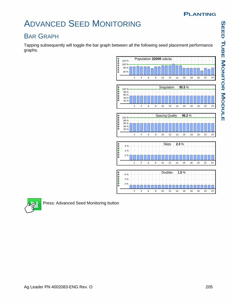
PLANTINGS
EE
D T
UB
E M
ON
ITO
R M
OD
UL
E
ADVANCED SEED MONITORING
BAR GRAPH
Tapping subsequently will toggle the bar graph between all the following seed placement performance graphs.
Press: Advanced Seed Monitoring button
2 4 6 8 10 12 14 16 18 20 22 24
120 %
100 %
80 %
60 %
Population 32000 sds/ac
2 4 6 8 10 12 14 16 18 20 22 24
100 %98 %96 %94 %
Singulation 95.5 %
92 %
2 4 6 8 10 12 14 16 18 20 22 24
100 %98 %96 %94 %92 %
Spacing Quality 96.2 %
2 4 6 8 10 12 14 16 18 20 22 24
6 %
4 %
2 %
Skips 2.3 %
2 4 6 8 10 12 14 16 18 20 22 24
6 %
4 %
2 %
Doubles 1.5 %
205 Ag Leader PN 4002083-ENG Rev. O

PLANTER PERFORMANCE SCREEN
• (A) All Rows
• (B) Hydraulic Drive
• (C) Bar Graph
• (D) Population
• (E) Spacing Quality
• (F) Singulation
• (G) Skips/Doubles
• (H) Seed Monitor Options
Advanced Seed Monitoring provides planter performance monitoring of seed meter singulation, skips/doubles and spacing quality, along with population and spacing information for all rows when planting compatible crops.
Display provides a full-screen planter performance view that includes display items and bar graphs for population, singulation, skips/doubles and spacing quality. In addition, Advanced Seed Monitoring automatically determines and displays the rows operating at the highest and lowest levels for singulation and population.
The Planter Performance screen displays planter averages for population, spacing quality, singulation, and skips/doubles. The screen also shows the averages for specific drive sections.
Bar graph can show individual row information for the averages shown on buttons (D-G).
• (A) All RowsDisplays the planter average for the four display items (D), (E), (F) and (G) at the bottom of the screen.
• (B) Hydraulic DriveDisplays the drive status, drive RPM, and target population for the hydraulic drive. There can be up to three displayed. Pressing the hydraulic drive channel will show the average of that section of the planter for the four display items at the bottom of the screen.
• (C) Bar GraphDisplays population, singulation, spacing quality, skips, and doubles, as selected by the operator.
• (D) PopulationDisplays the average population for t he planter, or sections of the planter, along with the highest and lowest population row.
• (E) Spacing QualityDisplays the average spacing quality for the planter, or selected sections of the planter, along with the highest and lowest.
- spacing quality is a measure of the percent of seeds being properly placed so that the spacing is as expected in the seed trench.
32000 sds/ac
32000
32000 sds/ac
38.4 ac 5.0 mph
All Rows
High Row:
Low Row:
1: 320
Spacing Quality:
Seed Spacing: 6.
1: 320
95
High Row:
Low Row:
1: 94.5 %
1: 94.5 %
Skips:
Doubles:
2.7 %
2.7 %
Population 94.5 %Singulation
Population
DKC53-45 59 rpm
Row 1:
206 Firmware Version 6.3

PLANTINGS
EE
D T
UB
E M
ON
ITO
R M
OD
UL
E
• (F) SingulationDisplays the average Singulation for the planter, or selected sections of the planter, along with the highest and lowest rows.
- singulation is a measure of the percent of seeds being properly metered so that one and only one seed drops from each seed cell of the seed meter.
• (G) Skips/DoublesDisplays the average skips and doubles for the planter
- skips are a measure of the percentage of seed expected to be planted that do not due to a seed not being dropped by the seed meter.
- doubles are a measure of the percentage of seed expected to be planted individually but instead two or more are dropped by the seed meter.
• (H) Seed Monitor SetupPressing this button brings up Seed Monitor Options screen.
Row Performance screen
The Row Performance screen displays information on specific rows.
Press: Bar Graph button. The Bar Graph button toggles between the Planter Performance screen and the Row Performance screen.
• (A) Row Indicator
• (B) Population
• (C) Spacing Quality
• (D) Seed Spacing
• (E) Singulation
• (F) Skips
• (G) Doubles
• (H) Singulation History/Spacing Quality History toggle
• (I) Errors
• (J) Bar Graph
• (K) Virtual Seed Trench
• (L) Play/Pause button
• (M) Zoom In
• (N) Zoom Out
Toggle through the rows using the arrow buttons or press on a specific row in the bar graph.
Previous Row button Next Row button
The Singulation History/Spacing Quality History bar graph gives a 10 second for each row.
38.4 ac 5.0 mph
Population
Spacing Quality
Seed Spacing
Singulation
Skips
Doubles
Row 1 Performance
Singulation History Errors: 0%
207 Ag Leader PN 4002083-ENG Rev. O

VIRTUAL SEED TRENCH
The virtual seed trench shows the placement of each seed of a problematic row to help determine if the problem is in the seed meter or seed tube. The yellow and red indicators show where there are seeding errors. The display does not log this information
• Double Skip Poor Spacing
• Play/Resume button
• Pause button
• Zoom In button
• Zoom Out button
208 Firmware Version 6.3

PLANTINGK
INZ
E P
LA
NT
ER
MO
NIT
OR
MO
DU
LE
PLANTING
KINZE PLANTER MONITOR MODULEThe KINZE Planter Monitor Module is a feature that displays planting data from a KINZE Population Monitor on the Map screen.
Note: Steps 1-4 must be performed by everyone who has purchased a KINZE Planter Monitor; steps 5-6 are performed by customers who have purchased those specific features.
1. KINZE Planter Monitor Module ConfigurationThis creates a configuration that is used for KINZE Planter Monitor operations.
2. Monitor Module setupIncluded front and rear unit settings, Shaft RPM sensor settings, and row spacing settings. This step allows the display to detect the physical KINZE Planter devices.
3. Sensor detection processThis allows the display to detect the proper number of muxbus sensors on the row units. For more information, see “Muxbus Sensor Detection” on page 211.
4. Set alarm thresholdsThis allows user-defined level at which the seed monitor alarms will sound. For more information, see “Alarms on KINZE Planter Monitor” on page 219.
5. Calibrate the Magnetic Pickup CoilThis step, which is performed by customers who have purchased the Magnetic Pickup Coil Speed Sensor allows the Monitor Module to receive data from this sensor, which measures the ground speed of the planter. For more information, see “KINZE Magnetic Coil Speed Sensor Calibration” on page 214.
6. EdgeVac® calibrationThis step, which is performed by customers who have purchased the EdgeVac® seed meters, allows the display to receive accurate data from the meters. For more information, see “KINZE EdgeVac Calibration” on page 215.
KINZE Planter Configuration
Press: Home button > Setup (wrench) button > Configuration (tractor) button > Configuration tab > your specific configuration > Setup (wrench) button > Seed Monitor button > Planter Configuration button
ConfigurationSelect Your Specific
Configuration
Seed Monitor Planter Configuration
209 Ag Leader PN 4002083-ENG Rev. O

• Front Units and Rear Units
Use / to adjust the number of front
and rear planting units, if necessary.
• Shaft RPM Sensors
Use / to adjust the number of Shaft
RPM Sensors, if necessary.
• Row SpacingShows the minimum row spacing of the planter.
Press to adjust the Row Spacing.
• Seed Size SensitivityChanges automatically with product type selection.
• ResetReturns settings to factory defaults, which allows operator to run Muxbus Sensor Detection again.
Ground Speed Settings
• Magnetic PickupCheck the Magnetic Pickup check box only if the planter is equipped with the Magnetic Pickup Sensor. This setting should then be left unchanged. For information on calibrating the Magnetic Coil Speed Sensor, see “KINZE Magnetic Coil Speed Sensor Calibration” on page 214
Note: Customers who do not have the magnetic pickup sensor who check this box will see a window stating “Bad Configuration: No Magnetic Pickup sensor currently found.”
• Speed SourceThe Speed Source drop-down box selects the type of speed source for the planter monitor. Choose between GPS, AUX (Auxiliary Input Module) and PMM.
Note: This speed selection only affects the PMM. The ground speed source must still be selected.
Other Sensors
Other check boxes on the Planter Configuration window include:
• Down PressureCheck this box if the planter has pneumatic down pressure.
• Oil SensorLeave this box unchecked.
• SDS SensorsLeave this box unchecked.
• Air CompressorCheck this box if the planter has an air compressor installed.
• Tank WeightCheck this box if the planter has a tank weight sensor install.
30 in
Magnetic Pickup
Shaft RPM Sensors
Planter Configuration
Front Units Rear Units
0 8
2
Row Spacing
Sensitivity
0
Ground Speed
Calibrate
PMM
Other Sensors
Down Press
Oil Sensor
SDS
Air Comp
Tank Weight
Speed Source
Reset
Planter Configuration
EdgeVac
Sensors
0
Calibrate
Tank Press
Calibrate
210 Firmware Version 6.3

PLANTINGK
INZ
E P
LA
NT
ER
MO
NIT
OR
MO
DU
LE
• EdgeVac Sensors
Use / to enter the number of EdgeVac® sensors on the planter. Calibrate EdgeVac sensors once a year. To start process, press the Calibrate button.
• Tank PressureCheck the box only if the planter is equipped with tank pressure sensor. Calibrate the sensor once a year. To start process, press Calibrate button.
EdgeVac
Use / to enter the number of EdgeVac® sensors.
Calibrate EdgeVac sensors once a year. To start process, press Calibrate button. For more information, see “KINZE EdgeVac Calibration” on page 215.
KINZE Sensor Configuration
Press: Home button > Setup (wrench) button > Configuration (tractor) button > Configuration tab > your specific configuration > Setup (wrench) button > Seed Monitor button > Sensor Configuration button
The Sensor Configuration screen is for system maintenance of the KINZE Population Monitor.
• The Install button installs a row sensor.
• Remove buttonRemoves the highlighted sensor of any type.
• Revive buttonAllows the display to reattempt communication with the highlighted sensor of any type.
• Ignore buttonTells the display to cease communications with a row sensor.
• View buttonShows the Sensor Information screen. For more information, see “Sensor Information” on page 213.
Note: After initial configuration of the KINZE Planter Monitor, complete the Sensor Muxbus Detection process. For more information, see “Muxbus Sensor Detection” on page 211.
Muxbus Sensor Detection
After initial configuration of the KINZE Planter Monitor, complete the Sensor Muxbus Detection process. This process allows the muxbus to detect each sensor on the planter. In order for the display to show the correct Planter Monitor information, complete the detection process for each muxbus sensor.
Note: Be sure that all sensors are unplugged before beginning the process. If any sensors are plugged in, the Muxbus Detection process will abort. If this occurs, unplug all sensors and retry procedure.
ConfigurationSelect Your Specific
Configuration
Seed Monitor Sensor Configuration
Rear Section
Row 1 OK
Row 2 OK
Row 3 OK
Row 4 OK
Row 5 OK
Row 6 OK
Row 7 OK
Install
Remove
Revive
Ignore
View
Item Status
Sensor Configuration
Row 8 OK
Row 9 OK
Row 10 OK
211 Ag Leader PN 4002083-ENG Rev. O

1. To start the Sensor Muxbus Detection process, make any settings changes necessary at the Planter
Configuration screen and then press . For more information on these settings, see “KINZE Sensor
Configuration” on page 211.
Note: The Muxbus detection process will only start if sensor configuration has changed.
2. Disconnect planter sensors from planter harnessMake certain all planter sensors are disconnected from the planter harness.
3. Accept the Muxbus Detection A screen appears, informing you that your configuration has changed and that it will require a muxbus
detection. Once all sensors are disconnected, press on the Configuration Changed screen. The
Muxbus Detection Process then begins.
4. Detect individual row units
Plug in each physical sensor plug into the muxbus wiring harness on the planter (from left to right). Follow the on-screen instructions.
Order of Muxbus Sensor Installation
Install the muxbus sensors in the following order:
• Rear Row Seed sensors from left to right.
• Front Row Seed sensors from left to right.- As shown from (A) to (B).
• Section Transmission sensors from left to right.
• Ground Speed Pickup Sensor.
• Auxiliary Sensors in the following order:- a. SDS Sensors.
- b. EdgeVac® Sensors.
- c. Pneumatic Down Pressure.
- d. Seed Scale Sensor, Air Compressor Sensor, and ASD Sensor.
Note: When the row unit sensor is plugged in, the display will beep once and show the status as “Calibrating.” When calibration is complete, the display will beep again and display either “OK” or “Slow”.
Row 1 OK
Row 2 OK
Row 3 OK
Row 4 OK
Row 5 OK
Row 6 OK
Row 7 OK
Item Status
Sensor Detection
Row 8 <Plug In>
Install muxbus sensors in the following order:
1. Rear Row Seed Sensors from left to right.
2. Front Row Seed Sensors from left to right.
3. Section Transmission sensors from left to right.
4. Ground Speed Pickup Sensor.
5. Auxiliary Sensors in the following order:
a. SDS Sensors
b. EdgeVac Sensors
c. Pneumatic Down Pressure
212 Firmware Version 6.3

PLANTINGK
INZ
E P
LA
NT
ER
MO
NIT
OR
MO
DU
LE
5. Resolve Any Possible ErrorsWhen the Muxbus Detection Process begins, each row unit will display “N/A” (Not Available) underneath the status. But as the Muxbus Detection process takes place, each row unit should state “Calibrating” for a time, then should indicate “OK”. After calibration, the sensor status displays either one of two different states:
• OK - The sensor is working and is communicating at 9600 baud.
• Slow - The sensor is working, but is communicating at 2400 baud.
Note: Some older KPM I, II, and III systems have slower sensors with black connectors, that communicate at a 2400 baud rate. The KPM I, II and III systems with blue connectors communicate at a 9600 baud rate. A slower baud rate does not result in decreased performance.
6. The display beeps once when the row unit sensor is plugged in, and will beep again when calibration is complete.
7. Detect CompleteWhen the Muxbus Detection process is complete, a message displays, stating “All sensors found”.
Sensor Information
Press: Home button > Setup (wrench) button > Configuration (tractor) button > Configuration tab > your specific configuration > Setup (wrench) button > Seed Monitor button > Sensor Configuration button > Highlight a Specific Row > View button
The Sensor Information screen displays hardware information for each seed tube sensor and also each seed sensor. Technical support may request that you look at this window for help in diagnosing a problem.
• IDa unique number for each sensor on the muxbus.
• Serial Numbervaries for each individual unit of seed sensor and seed tube sensor.
• Model Numbershared by each unit of the same model of seed tube sensor.
• Baud Ratethe speed of transmission between the muxbus sensor and the PMM module.
ConfigurationSelect Your Specific
Configuration
Seed Monitor Sensor Configuration Highlight Specific Row View
Sensor Information
ID: 1
Serial Number: 5678
Model Number: 1234
Baud Rate: 9600
213 Ag Leader PN 4002083-ENG Rev. O
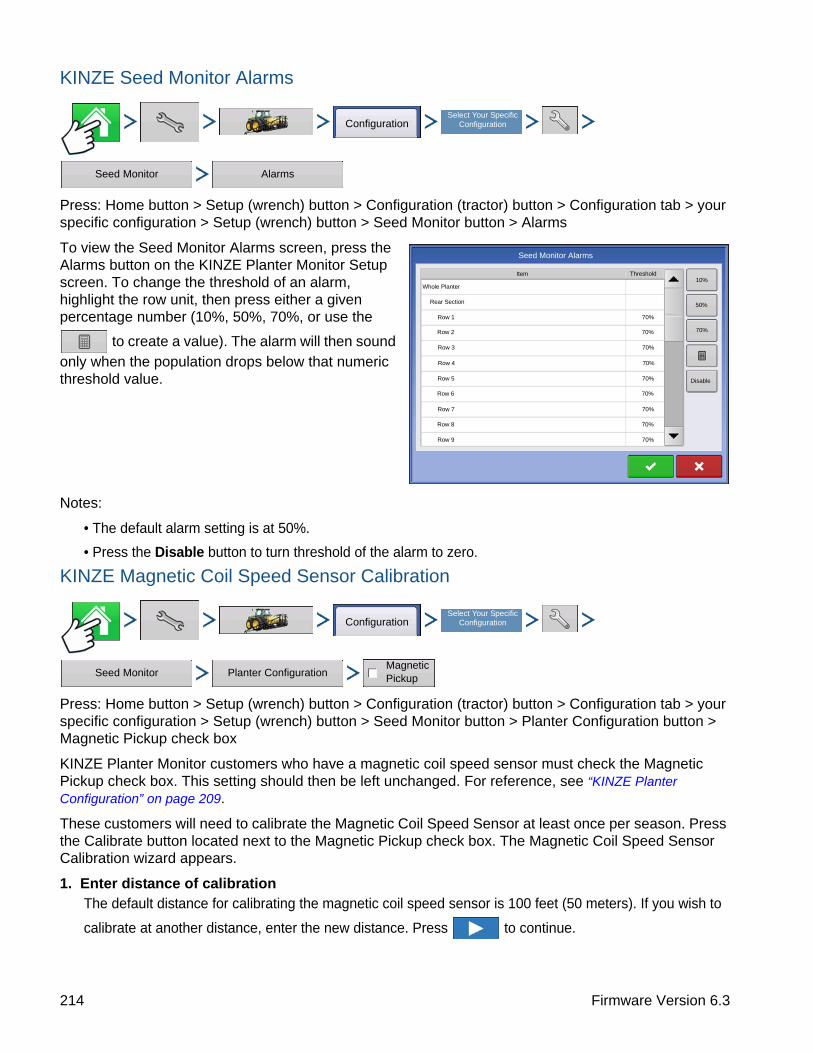
KINZE Seed Monitor Alarms
Press: Home button > Setup (wrench) button > Configuration (tractor) button > Configuration tab > your specific configuration > Setup (wrench) button > Seed Monitor button > Alarms
To view the Seed Monitor Alarms screen, press the Alarms button on the KINZE Planter Monitor Setup screen. To change the threshold of an alarm, highlight the row unit, then press either a given percentage number (10%, 50%, 70%, or use the
to create a value). The alarm will then sound only when the population drops below that numeric threshold value.
Notes:
• The default alarm setting is at 50%.
• Press the Disable button to turn threshold of the alarm to zero.
KINZE Magnetic Coil Speed Sensor Calibration
Press: Home button > Setup (wrench) button > Configuration (tractor) button > Configuration tab > your specific configuration > Setup (wrench) button > Seed Monitor button > Planter Configuration button > Magnetic Pickup check box
KINZE Planter Monitor customers who have a magnetic coil speed sensor must check the Magnetic Pickup check box. This setting should then be left unchanged. For reference, see “KINZE Planter Configuration” on page 209.
These customers will need to calibrate the Magnetic Coil Speed Sensor at least once per season. Press the Calibrate button located next to the Magnetic Pickup check box. The Magnetic Coil Speed Sensor Calibration wizard appears.
1. Enter distance of calibrationThe default distance for calibrating the magnetic coil speed sensor is 100 feet (50 meters). If you wish to
calibrate at another distance, enter the new distance. Press to continue.
ConfigurationSelect Your Specific
Configuration
Seed Monitor Alarms
Seed Monitor Alarms
10%
50%
70%
Disable
Row 1 70%
Row 2 70%
Row 3 70%
Row 4 70%
Row 5 70%
Row 6 70%
ThresholdItem
Whole Planter
Rear Section
Row 7 70%
Row 8 70%
Row 9 70%
ConfigurationSelect Your Specific
Configuration
Seed Monitor Planter ConfigurationMagnetic Pickup
214 Firmware Version 6.3

PLANTINGK
INZ
E P
LA
NT
ER
MO
NIT
OR
MO
DU
LE
2. Drive from start to end pointsPosition the vehicle at the start marker. Press the green-colored Start button and drive the vehicle for the predetermined distance.
Note: The display must be set on 0.0 before driving the calibration distance.
3. Stop at end of calibration distanceWhen the vehicle crosses the end marker of the predetermined distance, press the red-colored Stop button.
Press to continue to final step.
4. Calibration completeThe speed sensor calibration number has been calculated from the actual distance driven. Press FINISH to complete calibration and store the calculated value.
Notes:
• Calibration settings can be manually adjusted if desired by pressing Enter CAL Number and making small changes to the setting.
• To verify the calibration, repeat the previous steps.
KINZE EdgeVac Calibration
EdgeVac box
Press: Home button > Setup (wrench) button > Configuration (tractor) button > Configuration tab > your specific configuration > Setup (wrench) button > Seed Monitor button > Planter Configuration button > EdgeVac box > Calibrate button
Customers who have purchased the EdgeVac® seed meters should perform an EdgeVac Calibration once a year to make sure that it is correct.
Press the Calibrate button.
Press to enter the actual value taken from the hand-held calibration sensor at the vacuum
sensor.
Note: The appearance of this screen varies, depending upon whether you have one or two EdgeVac sensors.
KINZE PLANTER MONITOR OPTIONS
Press: Map button > Settings button > Planter Monitor tab
or
ConfigurationSelect Your Specific
Configuration
Seed Monitor Planter Configuration Calibrate
Settings Planter Monitor
215 Ag Leader PN 4002083-ENG Rev. O
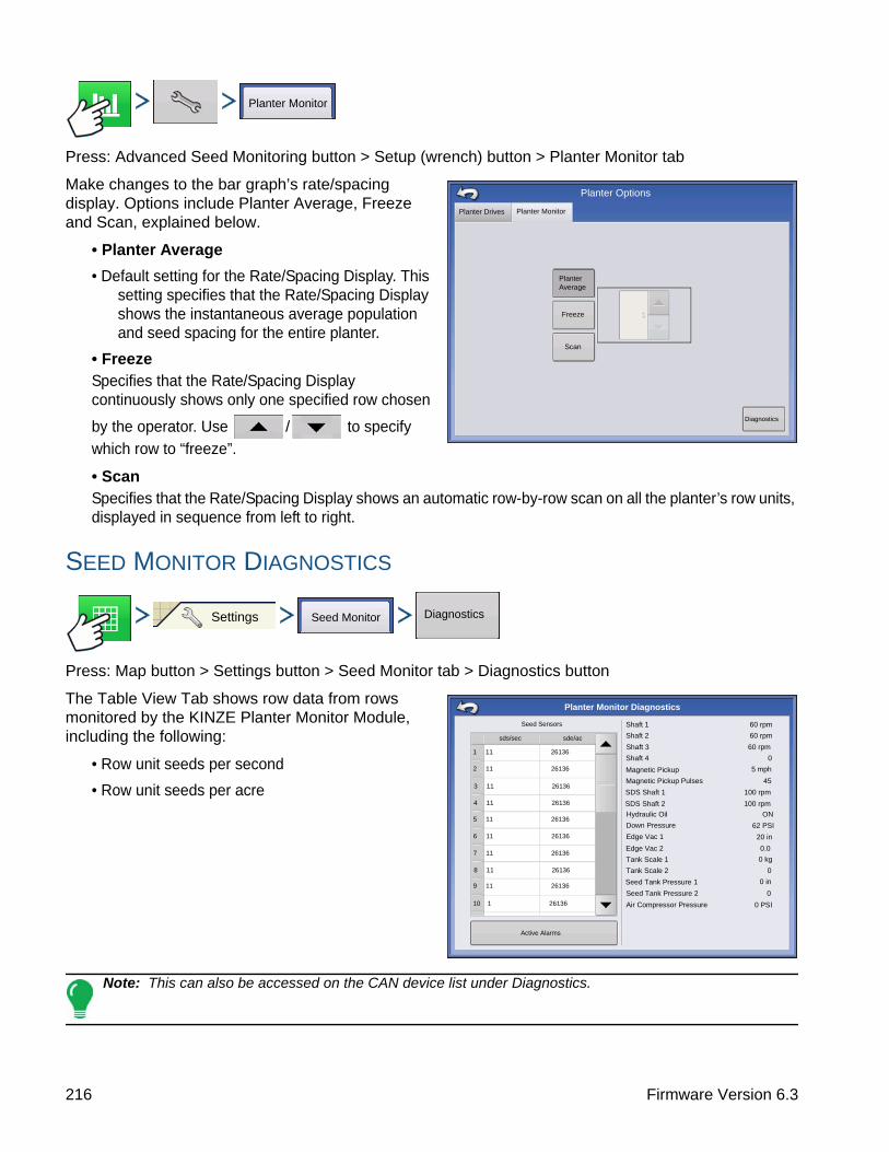
Press: Advanced Seed Monitoring button > Setup (wrench) button > Planter Monitor tab
Make changes to the bar graph’s rate/spacing display. Options include Planter Average, Freeze and Scan, explained below.
• Planter Average
• Default setting for the Rate/Spacing Display. This setting specifies that the Rate/Spacing Display shows the instantaneous average population and seed spacing for the entire planter.
• FreezeSpecifies that the Rate/Spacing Display continuously shows only one specified row chosen
by the operator. Use / to specify which row to “freeze”.
• ScanSpecifies that the Rate/Spacing Display shows an automatic row-by-row scan on all the planter’s row units, displayed in sequence from left to right.
SEED MONITOR DIAGNOSTICS
Press: Map button > Settings button > Seed Monitor tab > Diagnostics button
The Table View Tab shows row data from rows monitored by the KINZE Planter Monitor Module, including the following:
• Row unit seeds per second
• Row unit seeds per acre
Note: This can also be accessed on the CAN device list under Diagnostics.
Planter Monitor
Planter Options
Freeze
Scan
Planter Drives Planter Monitor
Diagnostics
Planter Average
Settings Seed Monitor Diagnostics
0 PSI
0 in
0 kg
20 in
62 PSI
5 mph
Seed Sensors
sds/sec sde/ac
1 11 26136
2 11 26136
4 11 26136
5 11 26136
6 11 26136
7 11 26136
8 11 26136
9 11 26136
Shaft 1 60 rpm
Shaft 2 60 rpm
Shaft 3 60 rpm
Shaft 4 0
Magnetic Pickup
Magnetic Pickup Pulses 45
SDS Shaft 1 100 rpm
SDS Shaft 2 100 rpm
Hydraulic Oil ON
Down Pressure
Edge Vac 1
Edge Vac 2 0.0
Tank Scale 1
Tank Scale 2 0
Seed Tank Pressure 1
Seed Tank Pressure 2 0
Air Compressor Pressure
3 11 26136
Active Alarms
10 1 26136
Planter Monitor Diagnostics
216 Firmware Version 6.3

PLANTINGK
INZ
E P
LA
NT
ER
MO
NIT
OR
MO
DU
LE
KINZE DISPLAY ITEMS ON EQUIPMENT TAB
The left-hand side of the Map screen’s Equipment Tab includes a number of display items that will vary depending upon the particular KINZE Planter Monitor Module configuration.
Press button shown below to advance to the next button.
Shaft Speed
The speed of the planter drive shafts, in RPM.
SDS - The speed of the planter seed delivery system (auger), in RPM.
EdgeVac Level - Measure of seed meter vacuum. This measurement, shown in inches of water, is displayed for each vacuum fan.
Pneumatic Down Pressure - Measure of down force the air bag places on the row unit.
Magnetic Pickup - Speed registered according to the magnetic pickup.
Tank Weight - The weight of seed in each tank.
Tank Area Left
The number of acres (hectares) that can be planted with the amount of seed remaining in the tanks.
Tank Pressure
The air pressure level for the Air Seed Delivery (ASD) system.
Down Force - Measure of force on gauge wheel and force being applied to row unit.
Swath: 40 ft 0 in
29000
30000
30000 30000
sds/ac 1
2
5.0 mph
1
Flow: 10560 sds/min
Applied: 9064.0 sds
Area: 0.33 ac
546R1
100%
38.4 ac
Population: 30000 sds/ac Spacing 30 in
Shaft SpeedPlanter Drives (rpm)
Settings
1 2 3
77 72 72
Outer Left
2 4 6 8 10 12 14 16 18 20 22 24 Inner Left
120 %
100 %80 %
60 %
Shaft Speed
Outer Left 60 rpm
Inner Left 60 rpm
217 Ag Leader PN 4002083-ENG Rev. O

Shown is an example of a KINZE Planter Monitor Module (PMM) with Row Shutoff and three Hydraulic Seed Control drives.
• (A) Mapping toolbox
• (B) Product Control toolbox
• (C) Meter RPM buttonAppears at the bottom left hand side of the Map screen, displays the number of hydraulic seed control motors and their speed, shown in Revolutions Per Minute (RPM). Pressing the Meter RPM button summons the Seed Rate Planter Control screen, to calibrate and prime the seed meters. For more information, see “Priming Seed Rate Meters” on page 181 and “Calibrating Seed Rate Meters” on page 182.
• (D) Master Switch Status
• (E) AutoSwath indicator
• (F) Section IndicatorsShown at the bottom of the Product Control Toolbox when the Map screen is shown in Zoom to Extent. When the Map screen is shown in the Zoom Details view or Perspective View, the section indicators are shown as a bar that appears behind the vehicle icon.
• (G) Population Monitor Bar GraphShows the number of row units as well as the instantaneous percentage planter average of seeds being distributed on each row unit.
• (H) Shaft SpeedDisplays the speed of the planter drive shafts, in RPM. Other KINZE PMM Map screen items are described at “KINZE Planter Monitor Options” on page 215 and also “KINZE Display Items on Equipment Tab” on page 217.
Planter Monitor Module screen
Press: Bar Graph button. The Planter Monitor Module screen displays information on machine performance.
Swath: 40 ft 0 in
29000
30000
30000 30000
sds/ac 1
2
5.0 mph
1
Flow: 10560 sds/min
Applied: 9064.0 sds
Area: 0.33 ac
546R1
100%
38.4 ac
Population: 30000 sds/ac Spacing 30 in
Shaft SpeedPlanter Drives (rpm)
Settings
1 2 3
77 72 72
Outer Left
2 4 6 8 10 12 14 16 18 20 22 24 Inner Left
120 %
100 %80 %
60 %
218 Firmware Version 6.3

PLANTINGK
INZ
E P
LA
NT
ER
MO
NIT
OR
MO
DU
LE
• Shaft SpeedThe speed of the planter drive shafts, in RPM.
• Tank WeightThe weight of seed in each tank of the ASD system.
• Tank Area LeftThe number of acres (hectares) that can be planted with the amount of seed remaining in the tanks of the ASD system.
• ASD Tank PressureThe air pressure level for the Air Seed Delivery (ASD) system.
• EdgeVac LevelMeasure of seed meter vacuum. This
measurement, shown in inches of water, is displayed for each vacuum fan.
• Pneumatic Down PressureMeasure of down force the air bag places on the row unit.
• Magnetic Pickup SpeedSpeed registered according to the magnetic pickup.
TROUBLESHOOTING
ALARMS ON KINZE PLANTER MONITOR
When the Active Alarms window is shown, use the scroll bar on the right hand side to locate the row
units where the alarm is occurring. Acknowledge the alarm by pressing . After dismissing the
alarm, you may continue planting, however, the alarm will continue showing in the title bar. You may also review the alarm information underneath the CAN device list shown underneath CAN Diagnostics.
The table below describes various alarms that may occur at system startup. The following pages describe errors that could occur during field operations.
Error Message: “Sensors calibrating wait for calibration”Possible Cause: PMM startup
Solution: Wait for Planter Monitor Module (PMM) to finish before beginning operation.
Error Message: “(Row #) sensor not detected”.Possible Cause: Population sensor did not begin communicating with the PMM.
Solution: Acknowledge the error by pressing OK. Check the LED on the sensor to see if it is working properly. If it has failed, then replace the sensor. Refer to the KINZE Planter Operator’s manual for further instructions.
Error Message: “Clean or replace sensor (Row #) as necessary”.Possible Cause: Population sensor dirty.
Solution: Press OK to dismiss the error. Then clean the sensor and restart the system.
34000 sds/ac
147 ac 74 ac
240 lb 117 lb 250 lb
7 in
20.0 in
5 mph
Spacing: 8 in
5.0 mph38.4 ac
Outer LeftInner LeftInner Right
60 rpm60 rpm60 rpm
C1291 59 rpm
Population: 26100 sds/ac
100 rpm100 rpm
ASDLeftRight
Weight Area Left
ASD Tank Pressure
Edge Vac LeftEdge Vac RightSDS LeftSDS RightMagnetic Pickup
High Low
20.0 in
250 lb
Gauge Wheel:
Down Force:
CSX56A11 CSZ192752 rpm 53 rpm
36000 sds/ac 38000 sds/ac
38000 34000
Population 36000 Down Force
60 %
80 %
100 %
120 %
12
34
56
78
910
1112
1314
1516
1718
1920
2123
2422
219 Ag Leader PN 4002083-ENG Rev. O

Error Message: “(Row #) mux bus data line short to mux bus ground”.Possible Cause: Population sensor’s mux bus signal wire is shorted to ground.
Solution: Press OK to dismiss the error. The display then replaces the message window with an alarm text on the header bar at the top of the Run screen. This alarm text continues until the wire is fixed or the sensor is disabled. Inspect the wire at the first opportunity.
Error Message: (Row #) mux bus data line short to mux bus power”.Possible Cause: Population sensor’s mux bus signal wire is shorted to power wire.
Solution: Press OK to dismiss the error. The display then replaces the message window with an alarm text on the header bar at the top of the Run screen. This alarm text continues until the wire is fixed or the sensor is disabled. Inspect the wire at the first opportunity.
Error Message: “(Row #) communication lost”.Possible Cause: Seed tube sensor stops communicating with the PMM.
Solution: Press OK to dismiss the error. The display then replaces the message window with an alarm text on the header bar at the top of the Run screen. This alarm text continues until the wire is fixed or the sensor is disabled. Inspect the sensor at the first opportunity.
Error Message: “(Inner or Outer; Right, or Left) Shaft Communication Lost”Possible Cause: Transmission sensor stops communicating with the PMM.
Solution: Press OK to dismiss the error. The display then replaces the message window with an alarm text on the header bar at the top of the Run screen. This alarm text continues until the wire is fixed or the sensor is disabled. Inspect the sensor at the first opportunity.
Error Message: “(Left or Right) Edge- Vac sensor communication lost”.Possible Cause: Edge-Vac sensor stops communication with the PMM.
Solution: Press OK to dismiss the error. The display then replaces the message window with an alarm text on the header bar at the top of the Run screen. This alarm text continues until the wire is fixed or the sensor is disabled. Inspect the sensor at the first opportunity.
Error Message: “(Left or Right) SDS shaft sensor communication lost”.Possible Cause: SDS shaft sensor stops communicating with the PMM.
Solution: Press OK to dismiss the error. The display then replaces the message window with an alarm text on the header bar at the top of the Run screen. This alarm text continues until the wire is fixed or the sensor is disabled. Inspect the sensor at the first opportunity.
Error Message: “Low hydraulic oil level”.Possible Cause: Hydraulic oil level drops.
Solution: Check oil level on the planter, add as necessary.
Error Message: “High hydraulic oil temperature”Possible Cause: Hydraulic oil temperature level rises
Solution: Stop planter in order to cool down oil temperature. Inspect for cause of overheating.
Error Message: “Voltage Error Alarm”.Possible Cause: Occurs if the battery voltage drops below 10 volts, or rises above 15 volts.
220 Firmware Version 6.3

PLANTINGK
INZ
E P
LA
NT
ER
MO
NIT
OR
MO
DU
LE
Solution: Check tractor’s electrical system.
Error Message: “(Row #) Seed Rate Alarm”.Possible Cause: The seed rate of one or more rows is less than the alarm threshold setting and the
corresponding transmission shaft sensor detects rotation.Solution: Press OK to dismiss the error. If the alarm state is still present, the graph will state
the rows where the errors are occurring, and the Title Bar will flash the type of alarm. Inspect row units to confirm that each has seed, and that all mechanical drive shaft parts are working properly.
Note: If desired, the alarm threshold for the row unit may be set to 0%, which will silence the seed rate alarm. However, the bar graph will continue to operate and the row will still be calculated in the planter average population. For instructions on changing the alarm threshold, see “KINZE Seed Monitor Alarms” on page 214.
Error Message: “Low Down Force Air Pressure”Possible Cause: Low pressure in the pneumatic down pressure system.
Solution: Press OK to dismiss the error. Check for air leaks and compressor failure.
Error Message: “Left (or Right) Tank Seed Level Low.Possible Cause: The Seed Scale weight has dropped below the entered threshold.
Solution: Press OK to dismiss the error. Refill the tank to clear the error completely.
Error Message: “Seed Tank Pressure Too Low.” Possible Cause: The minimum air flow for seed delivery is not present.
Solution: Press OK to dismiss the error. Check fan on the ASD system.
Error Message: Air Compressor Sensor Too Low.”Possible Cause: The minimum air compressor tank pressure is not present.
Solution: Press OK to dismiss the error. Check the air compressor.
221 Ag Leader PN 4002083-ENG Rev. O

222 Firmware Version 6.3

APPLICATIONL
IQU
ID R
AT
E C
ON
TR
OL
APPLICATION
APPLICATION
LIQUID RATE CONTROLDirectCommand allows the variable rate application of single or multiple liquid products. Follow the procedure below to create an operating configuration.
CREATE CONFIGURATION
Press: Home button > Setup (wrench) button > Configuration (tractor) button > Configuration tab > Add (+) button > Application button
1. Select Vehicle
Use drop-down menu to choose a vehicle, or press to enter a new vehicle. Press to
continue.
Note: If selecting Self-Propelled Sprayer from the drop-down menu skip steps 2 and 4.
2. Select Implement
Select an implement from the drop-down list menu, or press to create a new implement. Press
to continue.
3. Enter Implement Make and Model
Press to enter Make and Model name. Press to continue.
4. Select Implement Attachment Type
Use the drop-down list to select an implement attachment method. Press to continue.
5. Enter Hitch to Implement Axle Distance
Press to enter the hitch to implement axle distance. Press to accept.
6. Add Sprayer Functionality
Press to add sprayer functionality to the implement.
7. Select Controller
Use the drop-down menu to select a controller or press to add a controller. Press to
continue.
8. Assign Container Name
Container names default to Main Tank. Press to enter a new name if desired.
Configuration Application
Liquid Application
223 Ag Leader PN 4002083-ENG Rev. O

9. Assign Container Capacity
Press to enter the container capacity. Press to accept.
10. Enter Container Units
Use the drop-down menu to select the container units.
Once container has been configured press to continue.
11. Enter Swath Width
Press to enter swath width.
12. Enter Number of Boom Sections
Press / to enter number of boom sections.
13. Enter Boom Section Widths
Highlight specific boom section and press to enter boom width. The total width of all boom sections must equal swath width.
14. Enter Application Point Offset
Press to enter distance from hitch to application point (front to back). Press to accept
value on offset screen. Press to accept value for the application point.
Note: If setting up a Self-Propelled Applicator, enter the distance from rear axle to application point. Use drop-down menu to select distance Behind or In Front.
Note: At this point additional functionality can be added to the implement, such as direct injection.
If no additional functionality is being added, press to continue.
15. Add Additional Devices (optional)
Press to add boom control functionality.
Press to add boom sensor functionality.
• Press to enter sensing width (defaults to implement width, change only if necessary).
• Use / to enter number of sensors.
• Press Swath Offsets button to enter offsets. System can not be configured with sensors and application point on opposite sides of the hitch.
Press to continue.
Norac UC5
OptRx Crop Sensor
224 Firmware Version 6.3

APPLICATIONL
IQU
ID R
AT
E C
ON
TR
OL
16. Enter Hitch Point Offsets
Press check box if implement provides a hitch point. Press to enter distance and drop-down
menu to enter “to the left” or “to the right”. Press to enter distance Forward or Backward. Press
to continue.
17. Enter Implement Name
Press to enter a name for the implement. Press to continue.
18. Select Implement.
Press to continue.
19. Select Second Implement.
Use drop-down menu to select Implement or press to add second implement.
20. Select Speed SourceUse drop-down menu to select Primary Source, set Backup Source, and configure Auxiliary Channel. Press Calibrate Speed Sensor to launch the Speed Sensor Calibration Wizard.
21. Enter Configuration Name
A suggested name for the configuration appears. If desired, Press to enter a different name.
Press when complete.
The complete configuration should now appear under the Application heading located on the Configuration tab of the Configuration Setup screen.
The Operating Configuration is now able to be selected when starting a new Field Operation with the Field Operation Wizard. For more information, see “Setup Event” on page 45.
IMPLEMENT OFFSETS
Press: Home button > Setup (wrench) button > Configuration (tractor) button > Configuration tab > your specific configuration > Setup (wrench) button >Offsets button
ConfigurationSelect Your Specific
Configuration
Offsets
225 Ag Leader PN 4002083-ENG Rev. O
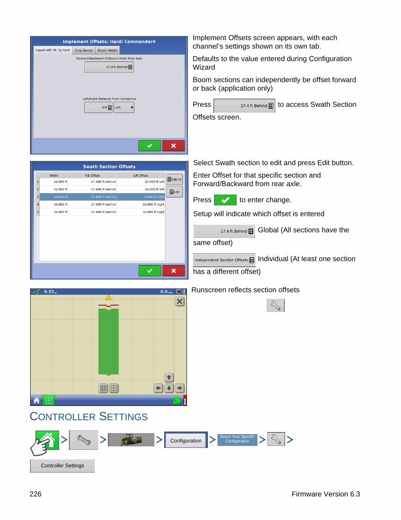
Implement Offsets screen appears, with each channel’s settings shown on its own tab.
Defaults to the value entered during Configuration Wizard
Boom sections can independently be offset forward or back (application only)
Press to access Swath Section
Offsets screen.
Select Swath section to edit and press Edit button.
Enter Offset for that specific section and Forward/Backward from rear axle.
Press to enter change.
Setup will indicate which offset is entered
Global (All sections have the
same offset)
Individual (At least one section
has a different offset)
Runscreen reflects section offsets
CONTROLLER SETTINGS
ConfigurationSelect Your Specific
Configuration
Controller Settings
226 Firmware Version 6.3
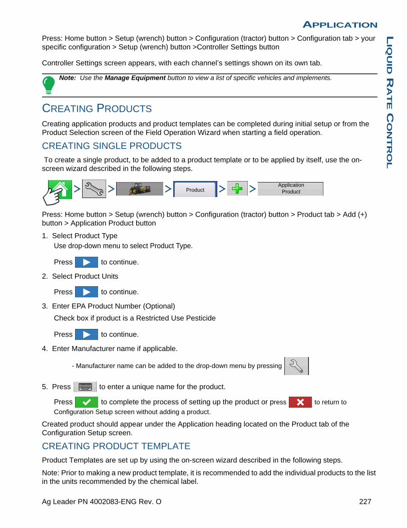
APPLICATIONL
IQU
ID R
AT
E C
ON
TR
OL
Press: Home button > Setup (wrench) button > Configuration (tractor) button > Configuration tab > your specific configuration > Setup (wrench) button >Controller Settings button
Controller Settings screen appears, with each channel’s settings shown on its own tab.
Note: Use the Manage Equipment button to view a list of specific vehicles and implements.
CREATING PRODUCTS
Creating application products and product templates can be completed during initial setup or from the Product Selection screen of the Field Operation Wizard when starting a field operation.
CREATING SINGLE PRODUCTS
To create a single product, to be added to a product template or to be applied by itself, use the on-screen wizard described in the following steps.
Press: Home button > Setup (wrench) button > Configuration (tractor) button > Product tab > Add (+) button > Application Product button
1. Select Product TypeUse drop-down menu to select Product Type.
Press to continue.
2. Select Product Units
Press to continue.
3. Enter EPA Product Number (Optional)
Check box if product is a Restricted Use Pesticide
Press to continue.
4. Enter Manufacturer name if applicable.
- Manufacturer name can be added to the drop-down menu by pressing
5. Press to enter a unique name for the product.
Press to complete the process of setting up the product or press to return to
Configuration Setup screen without adding a product.
Created product should appear under the Application heading located on the Product tab of the Configuration Setup screen.
CREATING PRODUCT TEMPLATE
Product Templates are set up by using the on-screen wizard described in the following steps.
Note: Prior to making a new product template, it is recommended to add the individual products to the list in the units recommended by the chemical label.
ProductApplication
Product
227 Ag Leader PN 4002083-ENG Rev. O

It is recommended to create product templates that contain the products applied for a crop type or time of the season.
Examples are:
• Pre-Emerge Burndown
• Post-Emerge Corn
• Post-Emerge Beans
• Insecticide
• Fungicide
In each template the products can be checked on/off for the mix when loaded at the run screen.
Note: Prior to making a new product template, it is recommended to add the individual products to the list in the units recommended by the chemical label.
It is recommended to create product templates that contain the products applied for a crop type or time of the season. Examples are:
- Pre-Emerge Burndown
- Post-Emerge Corn
- Post-Emerge Beans
- Insecticide
- Fungicide
In each template the products can be checked on/off for the mix when loaded at the run screen.
1. Press: Home button > Setup (wrench) button > Configuration (tractor) button > Product tab > Add (+) button > Mix/Blend button
2. From the Type drop-down menu select Tank Mix
From the Define By drop-down menu select:
• Total amounts - mix/blend defined by amounts added to the tank (total of each product in tank)
• Rate/acre - mix/blend defined by the amounts applied per acre (rate of each product applied/area)
Press to continue.
3. Set Base Amount or Rate by pressing to enter amount.
4. Enter a Base Amount and Units.
- Total Amounts - Tank/Bin Size
- Rate/Acre - For Rate Applied per Acre
Press to continue.
5. Select Carrier from drop-down menu.
Press to create a new carrier.
6. Press by the Add Mix/Blend Contents box to start the process of adding components to the
mix.
Product Mix / Blend
228 Firmware Version 6.3

APPLICATIONL
IQU
ID R
AT
E C
ON
TR
OL
7. Select the desired component from the drop-down menu. More than 7 products can be part of a template but 7 or fewer can be active at the same time.
A new product can be set up at this time by pressing and following the Product Setup Wizard.
Press to add selected product or press to return to Add Mix/Blend screen without adding
a product.
8. Press to add an additional component.
9. When all components have been added press .
10. Enter Manufacturer name if applicable.
- Manufacturer name can be added to the drop-down menu by pressing
11. Press to enter a unique name for the mix/blend.
Press to complete the process of setting up the mix/blend or press to return to
Configuration Setup screen without adding a mix.
The product mix/blend should appear under the Application heading located on the Product tab of the Configuration Setup screen.
Represents Product Templates
Represents Product Mixes prior to firmware version 5.4 and mixes exported from SMS
LOAD CONFIGURATION
1. Press: Select Event button.
Select a Season, Grower, Farm, and Field on the Management Selection screen. For more information, see “Setup Event” on page 45.
Select Event
229 Ag Leader PN 4002083-ENG Rev. O

2. Product Selection
Select product from the drop-down list or press
to create a new one.
3. Configure Product Mix
When using a product template, the mix contents and amounts are defined at the map screen by:
-a.activating or de-activating products
-b.changing rate or total amount of a product
-c.changing total amount of the product or overall rate of product application
These values can be changed on the Configure Product Mix screen which is available in the event setup wizard or by pressing a product line on the home screen.
A product can not be active with a rate of zero.
If a configuration is loaded with undetected modules, the Product Selection screen may show some grayed out (unavailable) options. The example to the left shows that the Direct Command module is active but Direct Injection, Crop Sensor, and Boom Control modules are grayed out and not functional.
When all product mixes have been configured press .
Product Selection
DC COM10K
DL1
Crop Sensor
Boom Control
Active
Active
Active
Select Product
Active 28% UAN
230 Firmware Version 6.3

APPLICATIONL
IQU
ID R
AT
E C
ON
TR
OL
4. Select Region and Controlling Product
Select Region from drop-down menu or use press keyboard button to name region.
Select Controlling Product for the Mix/Blend.
Press to complete the process of setting up
the dry blend or press to return to Home screen
without setting up an event.
MIX CALCULATOR
When a product template is setup using rate/area, the mix calculator can be used to show how much of each product to put in the tank when the user enters the desired amount to fill.
Press in the product information section of the home screen.
C12 0.0 lb/ac 0.0 lb 0.0 ac
0.0 lb/ac 0.0 lb 0.0 acCorn Post
231 Ag Leader PN 4002083-ENG Rev. O
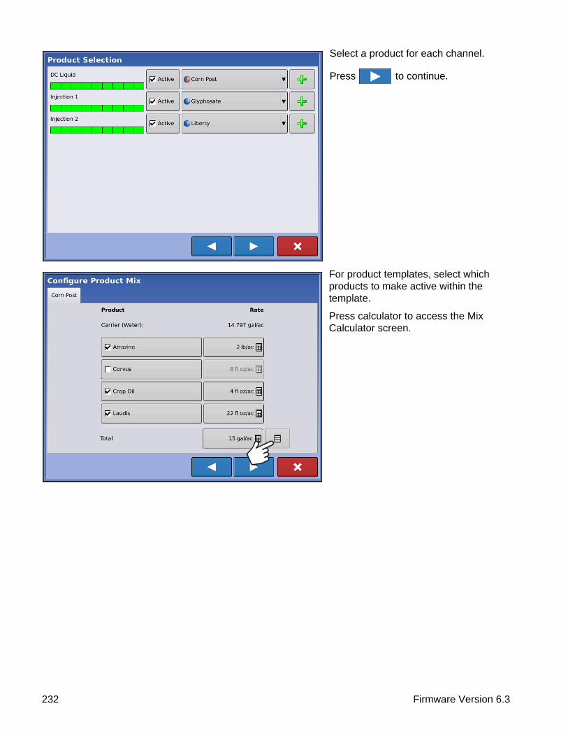
Select a product for each channel.
Press to continue.
For product templates, select which products to make active within the template.
Press calculator to access the Mix Calculator screen.
232 Firmware Version 6.3
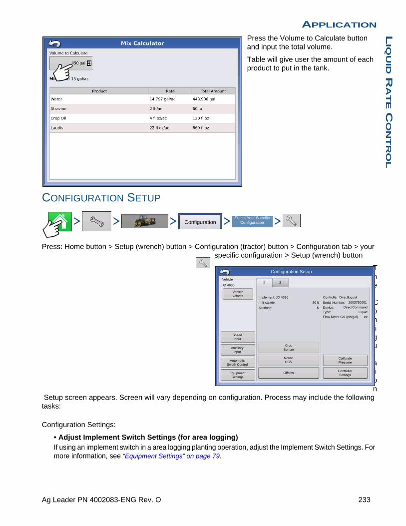
APPLICATIONL
IQU
ID R
AT
E C
ON
TR
OL
Press the Volume to Calculate button and input the total volume.
Table will give user the amount of each product to put in the tank.
CONFIGURATION SETUP
Press: Home button > Setup (wrench) button > Configuration (tractor) button > Configuration tab > your specific configuration > Setup (wrench) button
The Configuration
Setup screen appears. Screen will vary depending on configuration. Process may include the following tasks:
Configuration Settings:
• Adjust Implement Switch Settings (for area logging)If using an implement switch in a area logging planting operation, adjust the Implement Switch Settings. For more information, see “Equipment Settings” on page 79.
ConfigurationSelect Your Specific
Configuration
80 ft
Vehicle Offsets
Norac UC5
Crop Sensor
Speed Input
Auxiliary Input
Automatic Swath Control
Equipment Settings
Calibrate Pressure
Controller Settings
Offsets
Implement: JD 4630
Full Swath:
Sections: 5
Controller: DirectLiquid
Serial Number: 2003750001
Device: DirectCommand
Type: Liquid
Flow Meter Cal (pls/gal) inf
Vehicle
JD 46301 2
Configuration Setup
233 Ag Leader PN 4002083-ENG Rev. O

• Adjust Equipment Settings (for Rate Control)DirectCommand configurations should adjust settings at the Equipment Configuration Settings screen. For more information, see “Equipment Settings” on page 79.
• Speed Input SetupFor more information, see “Speed Input Settings” on page 80.
• Calibrate DistanceFor more information, see “Calibrate Distance” on page 81.
• AutoSwath settings (if using AutoSwath)For more information, see “AutoSwath” on page 84.
• GPS OffsetsAdjust GPS offsets for the Antenna Tab and the Hitch Tab. For more information, see “Vehicle Offsets” on page 85.
• Swath Section OffsetsFor more information, see “Swath Section Offsets” on page 86.
HARDI SAFE TRACK
Press: Home button > Setup (wrench) button > Configuration (tractor) button > Configuration tab > your specific configuration > Setup (wrench) button > Offsets button
When using Hardi ISOBUS, Implement Modeling can be set to Hardi SafeTrack. This allows display to accurately calculate path of sprayer.
Hardi SafeTrack Modeling is utilized by the display with SafeTrack is engaged on the machine.
LIQUID APPLICATION CONTROLLER SETTINGS
ConfigurationSelect Your Specific
Configuration
Offsets
0 ft 0 ft
20 ft
Implement Offsets: Hardi CM6000
Implement Liquid with Hardi ISOBUS
Implement Modeling
Implement Type
Hardi SafeTrack
Hitch to Axle Distance
Heading Aggressiveness
Implement Rear Hitch
Implement Provides a Rear Hitch
Front Hitch to Rear Hitch
2
Lateral Offset from Centerline
Left
ConfigurationSelect Your Specific
Configuration
Controller Settings
234 Firmware Version 6.3

APPLICATIONL
IQU
ID R
AT
E C
ON
TR
OL
Press: Home button > Setup (wrench) button > Configuration (tractor) button > Configuration tab > your specific configuration > Setup (wrench) button > Controller Settings button
The Controller Settings screen appears.
Make the following adjustments:
• Flow Meter CalibrationCalibration value representing the number of pulses that equal one-gallon of product flow through the controlling system.
• Flow Control DelaySetting that specifies a period of time from master switch on and the start of product application to the first flow control correction. This setting can be used to eliminate unwanted correction of flow control at the start of each pass. Typical setting values are 1 –2 seconds for liquid application control.
• Control Valve SettingsOpens the Control Valve Settings screen, which displays control valve settings for PWM, Servo, Calibrated Reflow and Ramsey Valve Controls. For more information, see below or for more settings see “Control Valve Settings - Servo, Calibrated Reflow and Ramsey Valve” on page 236.
• Close Flow Control Valve When Rate OffWhen this is selected, the controlling system shuts down when there is either a zero rate in the field or when entering an already-applied area. When unchecked, the controlling system remains in the last known state when the sections are shut off.
• Auxiliary Valve 1 & 2When all boom sections are off, this setting closes or opens an auxiliary valve. Choose settings for up to two auxiliary valves.
• Allowable ErrorDetermines the percent of error that is allowed prior to the product control system making any flow rate changes.
• ThreshholdThe user-defined percentage of actual rate error allowed before an alarm sounds.
• TimeoutThe number of seconds that an actual rate falls out of the error threshold before an alarm sounds.
120 pls/gal
Control Valve Settings
Flow Meter Calibration
Flow Control Delay
0 s
Rate Off
Flow Control Valve
Hole
Auxiliary Valve 1
Close
Auxiliary Valve 2
Close
Rate Error Alarm
Threshold
30 %
Timeout
5 s
Controller Settings
235 Ag Leader PN 4002083-ENG Rev. O

Control Valve Settings - PWM• PWM FrequencyThe frequency that the PWM control valve is pulsed at. Settings can be found from the manufacturer of the valve. Typical settings range from 100-125 Hz.
Note: See PWM valve manufacturer information for recommended settings.
• PWM GainDetermines how aggressively the control valve responds when making rate change adjustments. The higher the value the more aggressive the system response is.
• Zero Flow OffsetRepresents the maximum duty cycle that is sent to the control valve without producing any hydraulic flow from the PWM valve. Using too high of a Zero Flow Offset value can cause the product control system to not properly control low rates. See the PWM valve manufacturer information for recommended settings.
• PWM StandbyThis is a user-defined setting that determines the percent duty cycle the system uses when the booms are all off. The setting must be greater than the Zero Flow Offset.
Note: The current PWM Duty Cycle can be viewed at the Liquid Diagnostics screen. For more information, see “Liquid Application Diagnostics” on page 246
Control Valve Settings - Servo, Calibrated Reflow and Ramsey Valve• Valve Response 1Determines the speed of the servo valve when product control error exceeds the Response Threshold setting. The default for this setting is 100%. Decreasing the value will cause the servo valve to run slower. Valve Response 1 represents the fast speed of the servo valve.
• Valve Response 2Determines the speed of the servo valve when product control error is less than the Response Threshold setting. The default for this setting is 24%. Decreasing the value will cause the servo valve to run slower. Valve Response 2 represents the slow speed of the servo valve.
Control Valve Settings
PWM 12 voltControl Valve:
PWM Frequency
PWM Gain
Zero Flow Offset
PWM Standby 50
30
800
100Allowable
Error
2 %
3 gal/min
Control Valve Settings
Control Valve: Inline Servo
Valve Response 1
Valve Response 2
Response Threshold
100 24
Allowable Error
2 %
236 Firmware Version 6.3
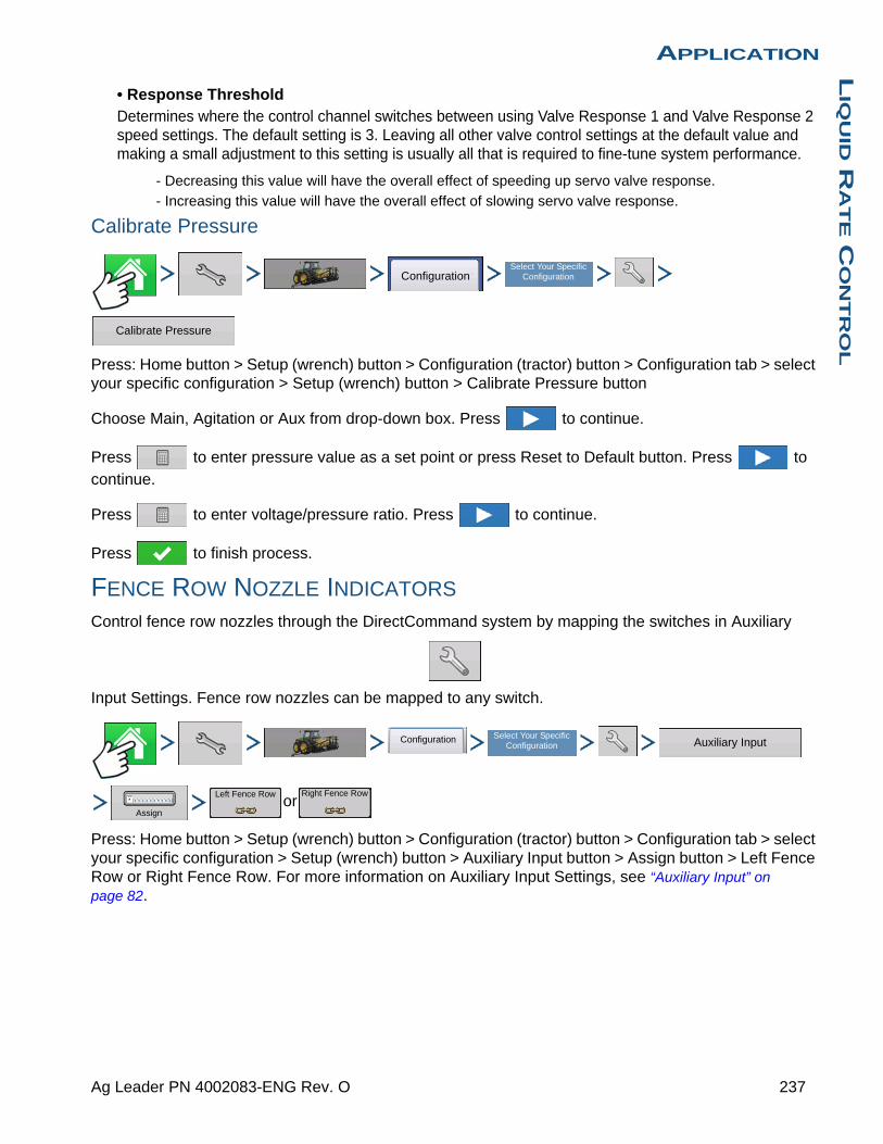
APPLICATIONL
IQU
ID R
AT
E C
ON
TR
OL
• Response ThresholdDetermines where the control channel switches between using Valve Response 1 and Valve Response 2 speed settings. The default setting is 3. Leaving all other valve control settings at the default value and making a small adjustment to this setting is usually all that is required to fine-tune system performance.
- Decreasing this value will have the overall effect of speeding up servo valve response.
- Increasing this value will have the overall effect of slowing servo valve response.
Calibrate Pressure
Press: Home button > Setup (wrench) button > Configuration (tractor) button > Configuration tab > select your specific configuration > Setup (wrench) button > Calibrate Pressure button
Choose Main, Agitation or Aux from drop-down box. Press to continue.
Press to enter pressure value as a set point or press Reset to Default button. Press to
continue.
Press to enter voltage/pressure ratio. Press to continue.
Press to finish process.
FENCE ROW NOZZLE INDICATORS
Control fence row nozzles through the DirectCommand system by mapping the switches in Auxiliary
Input Settings. Fence row nozzles can be mapped to any switch.
or
Press: Home button > Setup (wrench) button > Configuration (tractor) button > Configuration tab > select your specific configuration > Setup (wrench) button > Auxiliary Input button > Assign button > Left Fence Row or Right Fence Row. For more information on Auxiliary Input Settings, see “Auxiliary Input” on page 82.
ConfigurationSelect Your Specific
Configuration
Calibrate Pressure
Configuration Select Your Specific Configuration Auxiliary Input
Assign
Left Fence Row Right Fence Row
237 Ag Leader PN 4002083-ENG Rev. O

After specifying Fence Row Nozzle settings at the Auxiliary Input Assignment screen, the Fence Row Nozzle Indicators (A), which are shaped like triangles, appear on either side of the sections behind the vehicle icon.
Notes:
If a switch is selected as a Left or Right Fence Row Nozzle, the system sends power out of Boom Pin 11 for the left fence row, and Boom Pin 12 for the right fence row.
The boom sections next to the fence row nozzles must be turned on before the fence row nozzle can be turned on.
LOAD CONFIGURATION
Press: Select Event button.
Select a Season, Grower, Farm, and Field on the Management Selection
screen.
For more information, see “Setup Event” on page 45.
RUN CONFIGURATION
Once a configuration has been completed, the Map View button appears at the bottom of the Home screen. Press the Map View button to see the Map screen. The map below is displayed in Zoom to Detail view.
80 ft
47
43
41
Pressure (PSI)
630 gal
544.8 lb/min
150 150
lb/ac
2
1
130
150
15.0 mph38.4 ac
N
Flow:
Container:
100%
Main:
Agitation:
Auxiliary:
CoverageOverlap
Coverage
NH3
Select Event
238 Firmware Version 6.3

APPLICATIONL
IQU
ID R
AT
E C
ON
TR
OL
APPLICATION MAP SCREEN - ZOOM TO DETAIL
• (A) GPS Status
• (B) Ground Covered
• (C) Ground Speed
• (D) Diagnostics button
• (E) Product tab
• (F) Logging Status button
• (G) AutoSwath
• (H) Map View button
• (I) Home button
• (J) Display Legend
LEGEND SELECT
Press: Home button > Legend tab (of the Mapping Toolbox) > Setup (wrench) button
During Area Logging Application operations, the Map screen displays coverage in the Legend.
Use the drop-down menu at the top to select your product. Other items at this screen include:
• Press Coverage to show the area where you have already applied a product.
• If using a DirectCommand or rate logging configuration, press Rate to show the Rate Legend in the Mapping Toolbox. The rate map displays the actual rate being applied. This legend is editable. For more information, see “Legend Settings” on page 52.
• Press Clear Map to permanently remove all map data from the active field operation.
• Press Load Reference to load a map from a previous operation performed in that field to view as a background map.
80 ft 100%
41
Pressure (PSI)
630 gal
544.8 lb/min
130
150
lb/ac
150
15.0 mph19.2 ac
N
Coverage
CoverageOverlap
N
2
Flow:
Container:
Main:
Agitation:
Auxi
Load Reference
Coverage
NH3
Clear Map
Legend Select
239 Ag Leader PN 4002083-ENG Rev. O
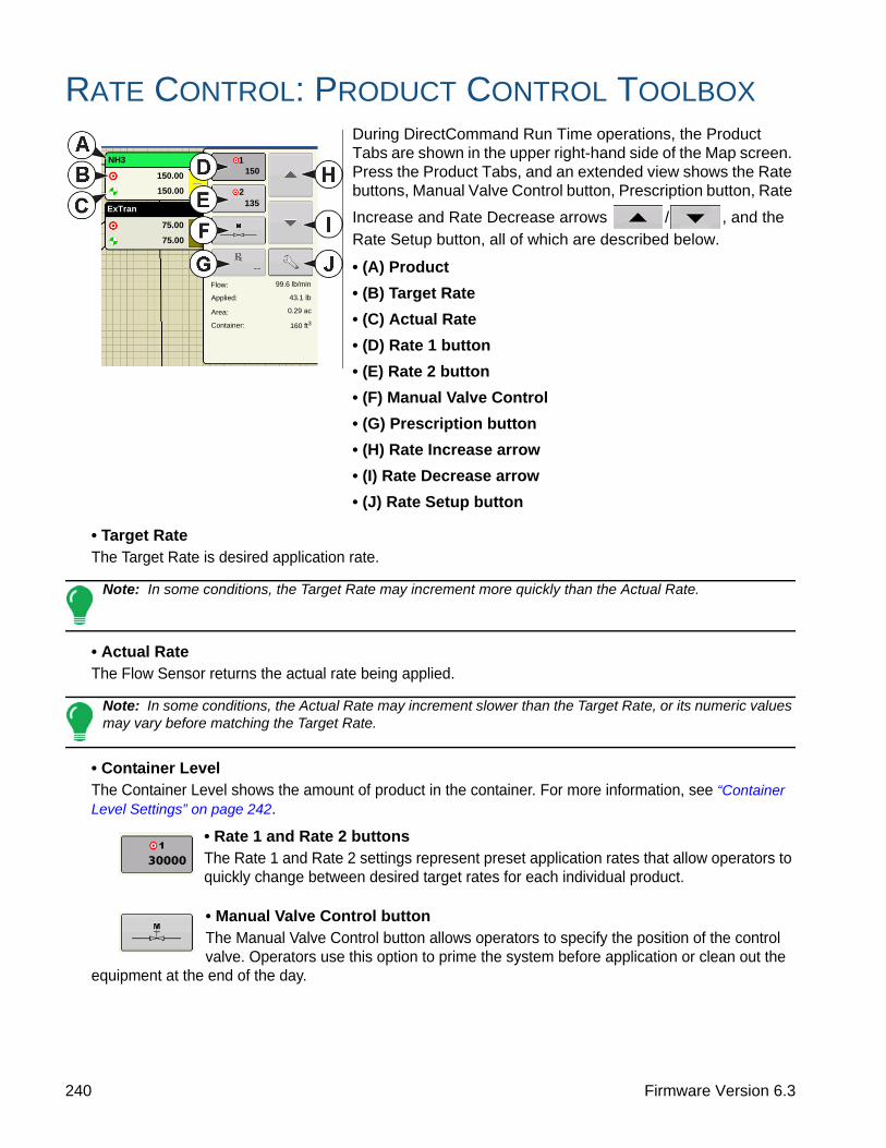
RATE CONTROL: PRODUCT CONTROL TOOLBOXDuring DirectCommand Run Time operations, the Product Tabs are shown in the upper right-hand side of the Map screen. Press the Product Tabs, and an extended view shows the Rate buttons, Manual Valve Control button, Prescription button, Rate
Increase and Rate Decrease arrows / , and the Rate Setup button, all of which are described below.
• (A) Product
• (B) Target Rate
• (C) Actual Rate
• (D) Rate 1 button
• (E) Rate 2 button
• (F) Manual Valve Control
• (G) Prescription button
• (H) Rate Increase arrow
• (I) Rate Decrease arrow
• (J) Rate Setup button
• Target RateThe Target Rate is desired application rate.
Note: In some conditions, the Target Rate may increment more quickly than the Actual Rate.
• Actual RateThe Flow Sensor returns the actual rate being applied.
Note: In some conditions, the Actual Rate may increment slower than the Target Rate, or its numeric values may vary before matching the Target Rate.
• Container LevelThe Container Level shows the amount of product in the container. For more information, see “Container Level Settings” on page 242.
• Rate 1 and Rate 2 buttonsThe Rate 1 and Rate 2 settings represent preset application rates that allow operators to quickly change between desired target rates for each individual product.
• Manual Valve Control buttonThe Manual Valve Control button allows operators to specify the position of the control valve. Operators use this option to prime the system before application or clean out the
equipment at the end of the day.
160 ft3
0.29 ac
43.1 lb
99.6 lb/minFlow:
Applied:
Area:
Container:
NH3
150.00
150.00
75.00
75.00
ExTran
150
135
1
2
240 Firmware Version 6.3
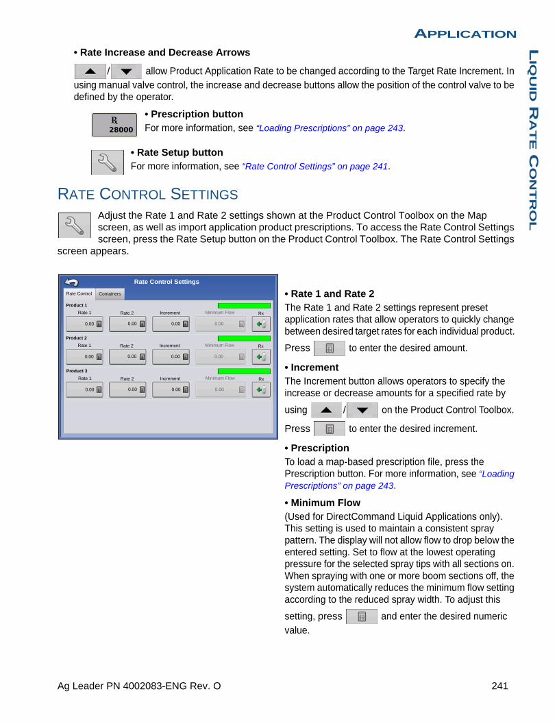
APPLICATIONL
IQU
ID R
AT
E C
ON
TR
OL
• Rate Increase and Decrease Arrows
/ allow Product Application Rate to be changed according to the Target Rate Increment. In using manual valve control, the increase and decrease buttons allow the position of the control valve to be defined by the operator.
• Prescription buttonFor more information, see “Loading Prescriptions” on page 243.
• Rate Setup buttonFor more information, see “Rate Control Settings” on page 241.
RATE CONTROL SETTINGS
Adjust the Rate 1 and Rate 2 settings shown at the Product Control Toolbox on the Map screen, as well as import application product prescriptions. To access the Rate Control Settings screen, press the Rate Setup button on the Product Control Toolbox. The Rate Control Settings
screen appears.
• Rate 1 and Rate 2The Rate 1 and Rate 2 settings represent preset application rates that allow operators to quickly change between desired target rates for each individual product.
Press to enter the desired amount.
• IncrementThe Increment button allows operators to specify the increase or decrease amounts for a specified rate by
using / on the Product Control Toolbox.
Press to enter the desired increment.
• PrescriptionTo load a map-based prescription file, press the Prescription button. For more information, see “Loading Prescriptions” on page 243.
• Minimum Flow(Used for DirectCommand Liquid Applications only). This setting is used to maintain a consistent spray pattern. The display will not allow flow to drop below the entered setting. Set to flow at the lowest operating pressure for the selected spray tips with all sections on. When spraying with one or more boom sections off, the system automatically reduces the minimum flow setting according to the reduced spray width. To adjust this
setting, press and enter the desired numeric value.
Rate Control Containers
Rate 1 Rate 2 Increment Minimum Flow
0.00 0.00 0.00 0.00
Rx
Product 1
Rate 1 Rate 2 Increment Minimum Flow
0.00 0.00 0.00 0.00
Rx
Product 2
Rate 1 Rate 2 Increment Minimum Flow
0.00 0.00 0.00 0.00
Rx
Product 3
Rate Control Settings
241 Ag Leader PN 4002083-ENG Rev. O

CONTAINER LEVEL SETTINGS
When filling or emptying container, use the Container Level portion of the Rate Control Settings screen to update the amount of product in the containers.
Container Level screen - (Partially Full)
Tank Fill
The Tank Fill button increases the container level logged in the display to the user-defined maximum volume (specified in the Container Setup Wizard).
Tank Empty
The Tank Empty button decreases the container level logged in the display to zero.
Tank Partial Fill
The Tank Partial Fill button increases the container level logged in the display to specific
amount that you specify by pressing . Pressing the Partial Fill button summons the
Adjust Container Amount screen.
Adjust Container Amount
• Add
Adds product to the container. Press to enter the amount.
• Remove
Removes product from the container. Press to enter the amount.
• SetSets the product level in the container. This button
summons the , where you can set a certain
amount. Choose an amount that is below your maximum container level.
Rate Control Containers
Full:
Current: 700
Tank 1 - Product 1
Rate Control Settings
800 80
10 %
Full:
Current: 400
Tank 2 - Product 2
400
Full:
Current: 200
Tank 3 - Product 3
200
40
10 %
20
10 %
Add product to the container
Remove product from the container
Set the product level in the container
Add
Remove
Set
Adjust Container Amount
242 Firmware Version 6.3
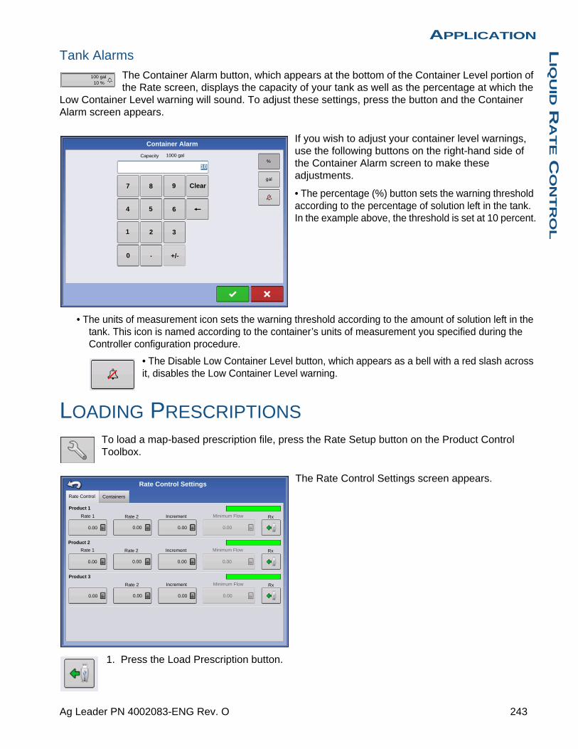
APPLICATIONL
IQU
ID R
AT
E C
ON
TR
OL
Tank Alarms
The Container Alarm button, which appears at the bottom of the Container Level portion of the Rate screen, displays the capacity of your tank as well as the percentage at which the
Low Container Level warning will sound. To adjust these settings, press the button and the Container Alarm screen appears.
If you wish to adjust your container level warnings, use the following buttons on the right-hand side of the Container Alarm screen to make these adjustments.
• The percentage (%) button sets the warning threshold according to the percentage of solution left in the tank. In the example above, the threshold is set at 10 percent.
• The units of measurement icon sets the warning threshold according to the amount of solution left in the tank. This icon is named according to the container’s units of measurement you specified during the Controller configuration procedure.
• The Disable Low Container Level button, which appears as a bell with a red slash across it, disables the Low Container Level warning.
LOADING PRESCRIPTIONSTo load a map-based prescription file, press the Rate Setup button on the Product Control Toolbox.
The Rate Control Settings screen appears.
1. Press the Load Prescription button.
100 gal10 %
1000 gal
Container Alarm
0
1 2 3
4 5 6
7 8 9 Clear
+/-.
Capacity
10%
gal
Rate Control Containers
Rate 1 Rate 2 Increment Minimum Flow
0.00 0.00 0.00 0.00
Rx
Rate 1 Rate 2 Increment Minimum Flow
0.00 0.00 0.00 0.00
Rx
Product 2
Rate 2 Increment Minimum Flow
0.00 0.00 0.00 0.00
Rx
Product 3
Rate Control Settings
Product 1
243 Ag Leader PN 4002083-ENG Rev. O

2. The File Selection screen appears.
3. Highlight the correct .AGSETUP (prescription) or
.shp (shape) file and press .
4. When you return to the Rate Control Settings screen, the prescription rate is now shown on the screen. The Load Prescription button has disappeared and in its place is the Remove Prescription button, which resembles a minus sign. Press the Remove Prescription button if you wish to remove the prescription from the field.
5. When you return to the Map screen, the prescription is now shown on the map.
SHOWING PRESCRIPTIONS ON THE MAP SCREEN
On the Map screen’s Mapping Toolbox, press the Legend Setup (wrench) tool and the Legend Select screen appears. Notice that the Rx (prescription) button appears at this screen.
1. Press the Rx button to show a legend of the prescription rate.
2. After pressing the Rx button, when you return to the Map screen, the prescription rate appears on the Prescription Rate Legend (A). This legend is not editable.
Name
Autopilot_dry.irx
demo_2_liquid.irx
demo_2_liquid_3_dry.irx
demo_3_liquid,irx
demo_3dry_1liq.irx
Field:
Product 1:
Roundup
File Selection
Demo Field
Planting
Application
Product 2:
Product 3:
Product 4:
Product 5:
SW 1/4
32% UAN
Balance Flexx
-
-
Load Reference
Glyphosate
Rate
Rx
Clear Map
Legend Select
Rx
0.67 ac
Flow:
Applied:
Area:
Container:
Pressure (PSI)
Main: 40
Agitation: 0
Auxiliary: 0
NH3 NH3
10.0 mph
281625.020.015.09.98
80 ft
544.8 lb/min
130
lb/ac
15.0 mph19.2 ac
130
130 100
8815.0 fl oz
800 gal
100%
100
Swath: 80 ft
100%
1.84 ac
244 Firmware Version 6.3

APPLICATIONL
IQU
ID R
AT
E C
ON
TR
OL
SHAPE FILE CONVERSIONWhat is commonly called a shape file is actually a collection of three different files. All three of the files are required and must be present on the USB drive for the system to use shape file groups for variable rate product application. A single "shape file" can contain recommendation rates for multiple products.
To begin, press the Rate Setup button on the Product Control Toolbox.
The Rate Control Settings screen appears.
1. Open File Selection screen.Press the Load Prescription button.
2. The File Selection screen appears. Highlight your
desired .shp file and press .
Note: Select the product and units that the shape file prescription was made for.
ExTran
Rate 1: 10.00
Rate 2: 8.00
Increment: 1.00
Prescription:
MInimum Flow:
Full: 800 gal
770 gal
80 gal
10 %
Current:
Rate Control Settings
0
Autopilot_dry.irx
demo_2_liquid.irx
demo_2_liquid_3_dry.irx
demo_3_liquid,irx
demo_3dry_1liq.irx
Field:
Product 1:
Roundup
File Selection
Demo Field
Planting
Application
Product 2:
Product 3:
Product 4:
Product 5:
3 mi
32% UAN
Balance Flexx
-
-
Name
245 Ag Leader PN 4002083-ENG Rev. O

3. Select Data From Shape FileSelect the column that contains the product recommendation rate. The list on the right side of the dialog shows sample data from the selected column.
4. Select UnitsSelect the controlling units for product application.
5. Default Rate SettingThe system assigns a default rate. Use the on-screen keypad to edit the value if desired.
CAUTION: Selection of the wrong data column or unit will result in misapplication of product.
Note: The only time the default rate is used by the system during product application is if the Rate Outside of Field selection is set to " Rx default". This setting is located in the equipment configuration settings portion of configuration setup. If the Rate Outside of Field selection is set to "Rx default", the default target rate will be
used when the vehicle exits the area covered in the prescription map.
LIQUID APPLICATION DIAGNOSTICS
To go to the Liquid Diagnostics screen, press on the Device Information button. At the Devices screen, highlight the item marked DC Liquid then press the Diagnostics button.
The Liquid Diagnostics screen includes the Active Controller Name and the Serial Number of the module. Other information provided includes the Main Pressure, Agitation Pressure, and Auxiliary Pressure. These raw sensor readings are shown in kilopascals (kPa).
Note: If you selected PWM as the Control Valve then the current PWM Duty Cycle is shown as a percentage number, in the PWM Duty Cycle (%) item on the Liquid Diagnostic screen.
• Flow Meter Signal Frequency (Hz)View the frequency generated by the flow meter during product application. Use this to make sure the flow meter is providing continuous feedback.
Select Prescription
Column
NH3
Units
gallons
Default Rate
50
Product: NH3
140
135
130
125
120
Column Preview
Controller Name
Serial Number
Main Pressure (kPa)
Agitation Pressure (kPa)
Auxiliary Pressure (kPa)
PWM Duty Cycle (%)
Flow Meter Signal Frequency (Hz)
Fow Meter Pulse Count
DirectLiquid
2003750001
738
662
655
2.55
0
0
Liquid Diagnostics
246 Firmware Version 6.3
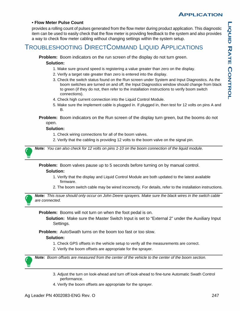
APPLICATIONL
IQU
ID R
AT
E C
ON
TR
OL
• Flow Meter Pulse Countprovides a rolling count of pulses generated from the flow meter during product application. This diagnostic item can be used to easily check that the flow meter is providing feedback to the system and also provides a way to check flow meter cabling without changing settings within the system setup.
TROUBLESHOOTING DIRECTCOMMAND LIQUID APPLICATIONS
Problem: Boom indicators on the run screen of the display do not turn green.Solution:
1. Make sure ground speed is registering a value greater than zero on the display.
2. Verify a target rate greater than zero is entered into the display.
3. Check the switch status found on the Run screen under System and Input Diagnostics. As the boom switches are turned on and off, the Input Diagnostics window should change from black to green (if they do not, then refer to the installation instructions to verify boom switch connections).
4. Check high current connection into the Liquid Control Module.
5. Make sure the implement cable is plugged in. If plugged in, then test for 12 volts on pins A and B.
Problem: Boom indicators on the Run screen of the display turn green, but the booms do not open.Solution:
1. Check wiring connections for all of the boom valves.
2. Verify that the cabling is providing 12 volts to the boom valve on the signal pin.
Note: You can also check for 12 volts on pins 1-10 on the boom connection of the liquid module.
Problem: Boom valves pause up to 5 seconds before turning on by manual control.Solution:
1. Verify that the display and Liquid Control Module are both updated to the latest available firmware.
2. The boom switch cable may be wired incorrectly. For details, refer to the installation instructions.
Note: This issue should only occur on John Deere sprayers. Make sure the black wires in the switch cable are connected.
Problem: Booms will not turn on when the foot pedal is on.Solution: Make sure the Master Switch Input is set to “External 2” under the Auxiliary Input
Settings.
Problem: AutoSwath turns on the boom too fast or too slow.Solution:
1. Check GPS offsets in the vehicle setup to verify all the measurements are correct.
2. Verify the boom offsets are appropriate for the sprayer.
Note: Boom offsets are measured from the center of the vehicle to the center of the boom section.
3. Adjust the turn on look-ahead and turn off look-ahead to fine-tune Automatic Swath Control performance.
4. Verify the boom offsets are appropriate for the sprayer.
247 Ag Leader PN 4002083-ENG Rev. O

Problem: No “As Applied” rateSolution:
1. Check cabling from the channel connection of the Liquid Control Module to the flow meter.
2. Check flow meter for product buildup and proper operation.
Problem: Rate is erraticSolution:
1. Verify that the rate display smoothing option is check marked in the setup of the configuration.
2. Check the controller settings of the active configuration. Verify that the valve setting for your particular type of control valve agree with the settings given in the Quick Reference Guide.
3. Use manual valve control to see if the rate stays constant.
Problem: Erratic behavior from the flow meter and boom valves.Solution: Verify that the display firmware and module firmware are both current.
Problem: No boom pressure at the start of the field.Solution: Before product application begins, use manual valve control to build boom
pressure. Select either Rate 1 or Rate 2 once pressure is set to desired level. Enter the pass and allow automatic control to take over once the sections are turned on.
Problem: AutoSwath checked on, but booms will not turn on.Solution:
1. Make sure the ground speed is registering a value greater than zero on the display and not in the covered area.
2. Make sure there is a target rate greater than 0.
3. Make sure the applicator is inside of the field boundary.
Problem: Booms turn off in the middle of the pass.Solution:
1. Check the display firmware and module firmware to see if they are the latest version released.
2. Make sure the ground speed does not go to 0.
3. Make sure the GPS is not losing the differential source.
Problem: Rate not responding (error flashing)Solution:
1. Make sure the flow meter calibration number matches the tag on the flow meter.
Note: For Raven flow meters, divide the calibration number by 10.
2. Make sure that the flow being applied is not greater than the pump can produce.
3. Use manual valve control to see if the control valve will open or close.
4. Check the tip manufacturer’s charts to make sure they are in the operating range of the application.
5. Check for any product buildup in the flow meter.
6. Check product filter for debris.
Problem: Booms turn on when outside of the boundary.Solution:
1. Make sure the Rate Outside of Field option is set to zero under the active configuration settings.
2. Make sure the Outside Boundary Option is set to Turn Section Off under the Automatic Swath Control options.
248 Firmware Version 6.3

APPLICATIONL
IQU
ID R
AT
E C
ON
TR
OL
3. Make sure there is not a gap between the boundary and the first pass of the headlands.
Note: For best results, run a new boundary when spraying the first pass of the headlands.
Problem: Booms turn on briefly (less than a second) in the headlandsSolution:
1. Make sure that the turn on look-ahead is greater than the turn off look-ahead.
2. Make sure GPS offsets are correct.
3. Make sure look aheads are less than three seconds each.
JOHN DEERE SPECIFIC INSTRUCTIONS
Here are some tips to remember when operating the display in conjunction with a SprayStar1 control system. Refer to the quick reference sheet and other sections of the operators manual for specific setup and operation instructions.
Master Switch InputAfter setting up a configuration in the display make sure to change the master switch input setting from standard to optional. This will tell the display to read the foot pedal for the master switch input status.
Master Switch UsageWhen manually shutting off all boom sections in the field, use the foot pedal switch. Leave the OEM master switch on the hydro handle ON during field use. Using the hydro handle switch may lead to improper field coverage, poor AutoSwath performance, and inaccurate spray records. Only use the John Deere master switch when completely shutting down the sprayer to transport or service the machine.
Target RateThe display must have a non-zero target rate entered in the display before the boom valves will open for product application. Ensure that the target rate entered into the display and SprayStar match to avoid any unwarranted alarms or warnings on the display.
Data CollectionThe display will create a coverage map of all product application while logging actual application rate from the product control system flow meter.
AutoSwath Boom Section ControlThe display will automatically control the boom section on/off status based upon previously applied area, field boundary, and internal boundaries.
SprayStar Application RateThe display will not control the rate based upon the target rate value entered into the system.
Application rate is controlled exclusively by the SprayStar display.
1. SprayStar is a trademark of Deere & Company.
249 Ag Leader PN 4002083-ENG Rev. O

SprayStar Rinse CycleWhen using the rinse cycle feature on the SprayStar, the display must have the boom sections on to allow the SprayStar to properly run the rinse routine. To ensure that boom sections are on:
1. Enter a target rate into the display.
2. Turn the foot pedal master switch on.
3. Turn all boom switches on.
4. Boom indicators on the Run screen must be blue showing that boom valves are on.
CONTROL VALVE SETTINGS
Liquid Product Control Valve Configuration Options• Inline ServoRate control is achieved through actuating a butterfly or ball valve found in the solution hose that goes to the booms. When the valve opens, the flow increases and when the valve closes, the flow decreases.
• Bypass ServoRate control is achieved through actuating a butterfly or ball valve found in the return line to the solution tank. When the valve opens, the flow decreases and when the valve closes the flow increases.
• PWM 12 voltRate control is achieved through speed changes to the solution pump. The PWM 12 Volt setting is programmed to pulse the power to an electric solenoid valve used to adjust the hydraulic flow to the solution pump.
• Pump ServoRate control is achieved through speed changes to the solution pump. The pump servo setting is programmed to control an electric motor used to actuate a hydraulic valve to adjust the hydraulic flow to the solution pump.
• PWM GroundRate control is achieved through speed changes to the solution pump. The PWM Ground setting is programmed to pulse the ground to an electric solenoid valve used to adjust the hydraulic flow to the solution pump.
• Calibrated ReflowThree-way boom valves are used to return product back to the tank in the off state. The returned flow is calibrated with adjustment at each valve. Calibration is required any time the nozzles are changed.
• Ramsey ValveA pneumatically-operated bypass valve. When air is supplied to the valve the rate increases; when air is released from the valve the rate decreases.
250 Firmware Version 6.3

APPLICATIONL
IQU
ID R
AT
E C
ON
TR
OL
SERVO CONTROL VALVE SETTINGS (BY MANUFACTURER)
Flow Control ValveControl Valve Configuration
Valve Response 1
Valve Response 2
Response Threshold
Raven Accu-Flow, 20 GPM Single Valve System (Fast Close Valve)
In-line servo 40% 10% 5
Raven Accu-Flow, 10 GPM Dual Valve System (Standard Valve)
In-line servo 100% 24% 5
Raven Accu-Flow, 30 GPM Single Valve System (Fast Close Valve
In-line servo 40% 10% 5
Raven Accu-Flow, 30 GPM Dual Valve System (Standard Valve)
In-line servo 100% 24% 5
Raven Flow Control Valve, 3/4" (Standard Valve)
In-line or Bypass Servo
100% 24% 1
Raven Flow Control Valve, 3/4" (Fast)
In-line or Bypass Servo
40% 10% 5
Raven Flow Control Valve, 1" (Standard)
In-line or Bypass Servo
100% 24% 2
Raven Flow Control Valve, 1" (Fast)
In-line or Bypass Servo
40% 10% 5
Raven Flow Control Valve, 1 1/2" (Standard)
In-line or Bypass Servo
100% 24% 3
Raven Flow Control Valve, 2" (Standard)
In-line or Bypass Servo
100% 24% 8
Raven Flow Control Valve, 2" (Fast)
In-line or Bypass Servo
40% 10% 15
Raven Flow Control Valve, 3" (Standard)
In-line or Bypass Servo
100% 24% 15
Mid-Tech, 3/4”In-line or Bypass
Servo40% 10% 5
Mid-Tech, 1”In-line or Bypass
Servo40% 10% 8
Mid-Tech, 1 1/2”In-line or Bypass
Servo40% 10% 11
Mid-Tech, 2”In-line or Bypass
Servo40% 10% 15
251 Ag Leader PN 4002083-ENG Rev. O
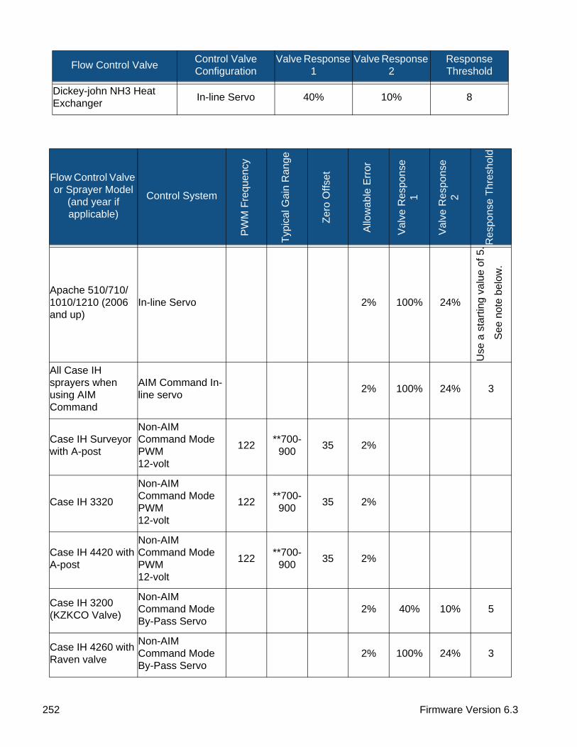
Dickey-john NH3 Heat Exchanger
In-line Servo 40% 10% 8
Flow Control Valve or Sprayer Model
(and year if applicable)
Control System
PW
M F
requ
ency
Typ
ical
Gai
n R
ange
Zer
o O
ffset
Allo
wab
le E
rror
Val
ve R
espo
nse
1
Val
ve R
espo
nse
2
Res
pons
e T
hres
hold
Apache 510/710/ 1010/1210 (2006 and up)
In-line Servo 2% 100% 24%
Use
a s
tart
ing
valu
e of
5.
See
not
e be
low
.
All Case IH sprayers when using AIM Command
AIM Command In-line servo
2% 100% 24% 3
Case IH Surveyor with A-post
Non-AIM Command Mode PWM 12-volt
122**700-900
35 2%
Case IH 3320
Non-AIM Command Mode PWM12-volt
122**700-900
35 2%
Case IH 4420 with A-post
Non-AIM Command Mode PWM12-volt
122**700-900
35 2%
Case IH 3200 (KZKCO Valve)
Non-AIM Command Mode By-Pass Servo
2% 40% 10% 5
Case IH 4260 with Raven valve
Non-AIM Command Mode By-Pass Servo
2% 100% 24% 3
Flow Control ValveControl Valve Configuration
Valve Response 1
Valve Response 2
Response Threshold
252 Firmware Version 6.3
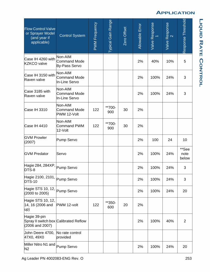
APPLICATIONL
IQU
ID R
AT
E C
ON
TR
OL
Case IH 4260 with KZKCO valve
Non-AIM Command Mode By-Pass Servo
2% 40% 10% 5
Case IH 3150 with Raven valve
Non-AIM Command Mode In-Line Servo
2% 100% 24% 3
Case 3185 with Raven valve
Non-AIM Command Mode In-Line Servo
2% 100% 24% 3
Case IH 3310Non-AIM Command Mode PWM 12-Volt
122**700-900
30 2%
Case IH 4410Non-AIM Command PWM 12-Volt
122**700-900
30 2%
GVM Prowler (2007)
Pump Servo 2% 100 24 10
GVM Predator Servo 2% 100% 24%**See note
below
Hagie 284, 284XP, DTS-8
Pump Servo 2% 100% 24% 3
Hagie 2100, 2101, DTS-10
Pump Servo 2% 100% 24% 3
Hagie STS 10, 12, (2000 to 2005)
Pump Servo 2% 100% 24% 20
Hagie STS 10, 12, 14, 16 (2006 and up)
PWM 12-volt 122**350-600
20 2%
Hagie 39-pin Spray II switch box (2006 and 2007)
Calibrated Reflow 2% 100% 40% 2
John Deere 4700, 47X0, 49X0
No rate control provided
Miller Nitro N1 and N2
Pump Servo 2% 100% 24% 20
Flow Control Valve or Sprayer Model
(and year if applicable)
Control System
PW
M F
requ
ency
Typ
ical
Gai
n R
ange
Zer
o O
ffset
Allo
wab
le E
rror
Val
ve R
espo
nse
1
Val
ve R
espo
nse
2
Res
pons
e T
hres
hold
253 Ag Leader PN 4002083-ENG Rev. O
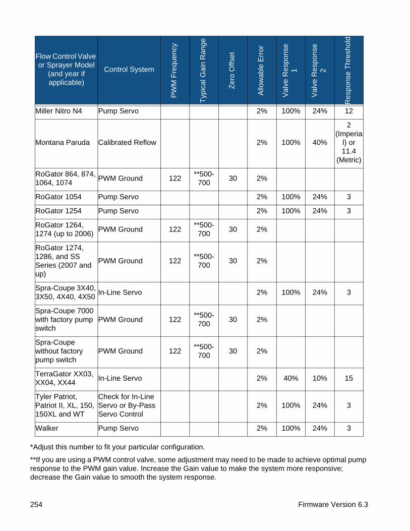
*Adjust this number to fit your particular configuration.
**If you are using a PWM control valve, some adjustment may need to be made to achieve optimal pump response to the PWM gain value. Increase the Gain value to make the system more responsive; decrease the Gain value to smooth the system response.
Miller Nitro N4 Pump Servo 2% 100% 24% 12
Montana Paruda Calibrated Reflow 2% 100% 40%
2 (Imperia
l) or 11.4
(Metric)
RoGator 864, 874, 1064, 1074
PWM Ground 122**500-700
30 2%
RoGator 1054 Pump Servo 2% 100% 24% 3
RoGator 1254 Pump Servo 2% 100% 24% 3
RoGator 1264, 1274 (up to 2006)
PWM Ground 122**500-700
30 2%
RoGator 1274, 1286, and SS Series (2007 and up)
PWM Ground 122**500-700
30 2%
Spra-Coupe 3X40, 3X50, 4X40, 4X50
In-Line Servo 2% 100% 24% 3
Spra-Coupe 7000 with factory pump switch
PWM Ground 122**500-700
30 2%
Spra-Coupe without factory pump switch
PWM Ground 122**500-700
30 2%
TerraGator XX03, XX04, XX44
In-Line Servo 2% 40% 10% 15
Tyler Patriot, Patriot II, XL, 150, 150XL and WT
Check for In-Line Servo or By-Pass Servo Control
2% 100% 24% 3
Walker Pump Servo 2% 100% 24% 3
Flow Control Valve or Sprayer Model
(and year if applicable)
Control System
PW
M F
requ
ency
Typ
ical
Gai
n R
ange
Zer
o O
ffset
Allo
wab
le E
rror
Val
ve R
espo
nse
1
Val
ve R
espo
nse
2
Res
pons
e T
hres
hold
254 Firmware Version 6.3
APPLICATIONL
IQU
ID R
AT
E C
ON
TR
OL
LIQUID SERVO SETTINGS DESCRIPTION
• Valve Response 1Default Value: 100%
Determines the speed of the servo valve when product control error exceeds the Response Threshold setting.
Decreasing the value will cause the servo valve to run slower.
• Valve Response 2Default Value: 24%
Determines the speed of the servo valve when product control error is less than the Response Threshold setting.
Decreasing the value will cause the servo valve to run slower.
• Allowable ErrorDefault Value: 2%
Determines the percent of error that is allowed prior to the product control system making any flow rate corrections.
2% - 3% is the normal dead band setting range.
- Too low of a setting value can cause the product control system to continually hunt for the target application rate.
- Too high of a setting will cause excessive product application error.
• Response ThresholdDefault Value: 3
Determines where the control system switches between using Valve Response 1 or Valve Response 2 speed setting.
Leaving all other valve control settings at the default value and making a small adjustment to this setting is usually all that is required to fine tune system performance.
- Decreasing this value will have the overall effect of speeding up servo valve response.
- Increasing this value will have the overall effect of slowing servo valve response.
LIQUID PWM CONTROL VALVE SETTINGS DESCRIPTION
• PWM FrequencyDefault Value: 100
The frequency that the PWM control valve is pulsed at. Typical settings range from 100 - 125. See PWM valve manufacturer information for recommended settings.
• GainDefault Value: 800
This setting determines how aggressively the control valve responds when making rate change adjustments. The higher the value the more aggressive the system response is.
• Zero OffsetDefault Value: 30
This setting represents the maximum duty cycle that is sent to the control valve without producing any hydraulic flow from the PWM valve. Using too high of a Zero Offset value can cause the product control system to not properly shut off. See PWM valve manufacturer information for recommended settings.
255 Ag Leader PN 4002083-ENG Rev. O
• Allowable ErrorDefault Value: 2%
2% - 3% is the normal dead band setting range.
- Too low of a setting value can cause the product control system to continually hunt for the target application rate.
- Too high of a setting will cause excessive product application error.
DICKEY-JOHN NH3 CONVERSIONS
Conversion Formulas
The following formulas can be used to convert the Dickey John flow sensor constant to a value that represents pulses/gallon of anhydrous ammonia for use by the display.
Note: The flow sensor constant is tagged on the Dickey-John flow meter. The density setting comes from a chart in the Dickey-John documentation and is not provided in this manual.
TROUBLESHOOTING SERIAL CONTROL APPLICATIONS Problem: Rate changes on the display, but not on the controlled console.
Solution: 1. Verify the current firmware is running on the display and Application Rate module.
2. Check the settings specific to your controlled console. (For more information, refer to the Quick Reference Guide).
3. Check cabling and all connections.
4. Disconnect the serial connection and determine if the controller is functioning properly without the display.
Problem: The display rate and serial-controlled rate do not match.Solution:
1. Verify the current firmware is running on the display and the Application Rate Module.
2. Check the percent rate change. (Refer to the Quick Reference Guide for more information).
Conversion Formula
Formula for flow meter calibration for Dickey John reading pounds of anhydrous
Flow sensor constant (pulses/in3) X 1728 (in3/ft3) X 5.11 (lbs of anhydrous/gal)
Solution: Density (lbs. of anhydrous/ft3)
Formula for flow meter calibration for Dickey John reading pounds of Nitrogen
Flow sensor constant (pulses/in3) X 1728 (in3/ft3) X 4.22 (lbs of N/gal)
Density (lbs. of N/ft3)
256 Firmware Version 6.3

APPLICATIONL
IQU
ID R
AT
E C
ON
TR
OL
MISCELLANEOUS
GLOSSARY OF APPLICATION SETTINGS
Configuration Settings• Rate Outside of Field Rate that will be used outside of the field boundary. Zero stops product application. Last Good uses the previous rate before exiting the boundary. Rx Default uses the default rate written in the prescription file loaded.
• Rate Display SmoothingDetermines how the feedback from the control channel’s rate sensor will be displayed on the run screen. When checked, the system will display the target rate when the application rate is within 10% of the target rate setting. When unchecked the system will display the raw feedback from the rate sensor.
• Minimum FlowThis setting is used to maintain a consistent spray pattern. The display will not allow flow to drop below the entered setting. Set to flow at the lowest operating pressure for the selected spray tips with all sections on. When spraying with one or more boom sections off, the system automatically reduces the minimum flow
setting according to the reduced spray width. To adjust this setting, Press and enter the desired numeric value.
• Controller Time DelayCompensates for any delay in the control system when changing between different product flow rates during variable rate application.
Speed Input Settings• Primary Speed SourceMain speed input source used by the display.
• Backup Speed SourceIf the primary speed source fails, the display will use the backup if one is available.
• Manual Speed If both of the speed input sources are unavailable, manual speed can be used in order for the control channel to provide application. Manual speed setting is for use during static machine testing or by the control system in the absence of primary and backup speed signals.
Automatic Swath Control Settings• Turn-On Look-AheadDetermines how far ahead the system looks to turn the swath sections back on. This setting compensates for any delay in the product control system when the sections are turned on.
• Turn-Off Look-AheadDetermines how far ahead the system looks to turn the swath sections off. This setting compensates for delay in the product control system when the boom sections are turned off.
• Outside Boundary OptionDetermines the behavior of the sections when exiting the field boundary or prescription-mapped area.
257 Ag Leader PN 4002083-ENG Rev. O

• Coverage OptionBased on the coverage option selected, this setting determines the behavior of the swath section when entering/exiting an already applied area or field boundary. Options available include: Minimize Skip, Minimize Overlap, and User Defined Percentage.
Auxiliary Input Settings• Master SwitchSwitch that performs global master control of all rate control channels.
• F1-F11Settings determine the switch(es) that will operate the controlling channel specified from the configuration setup. Single switches can be used to control multiple channels and swath sections.
Controller Settings• Flow Meter CalCalibration value representing the number of pulses that equal one-gallon of product flow through the controlling system.
• Control Valve ConfigurationSetting specifies the type of control valve being used for the rate control functions of the controlling system.
• Response ThresholdDetermines where the control channel switches between using Valve Response 1 and Valve Response 2 speed setting.
• Valve Response 1Determines the speed of the servo valve when product control error exceeds the Response Threshold setting. Valve Response 1 represents the fast speed of the servo valve.
• Valve Response 2Determines the speed of the servo valve when product control error is less than the Response Threshold setting. Valve Response 2 represents the slow speed of the servo valve.
• Allowable ErrorDetermines the percent of error that is allowed prior to the product control system making any flow rate changes.
• Flow Control DelaySetting for period of time from master switch on and the start of product application to the first flow control correction. This setting can be used to eliminate unwanted correction of flow control at the start of each pass. Typical setting values are zero for granular and 1 –2 seconds for liquid application control.
• Close Flow Control Valve When Rate OffWhen selected the controlling system will shut down when there is either a zero rate in the field or entering an already applied area. When unchecked the controlling system will stay in the last known state when the sections are shut off.
• PWM FrequencyThe frequency that the PWM control valve is pulsed at. Settings can be found from the manufacturer of the valve. Typical settings range from 100-125 Hz.
• PWM GainDetermines how aggressively the control valve responds when making rate change adjustments. The higher the value the more aggressive the system response is.
258 Firmware Version 6.3
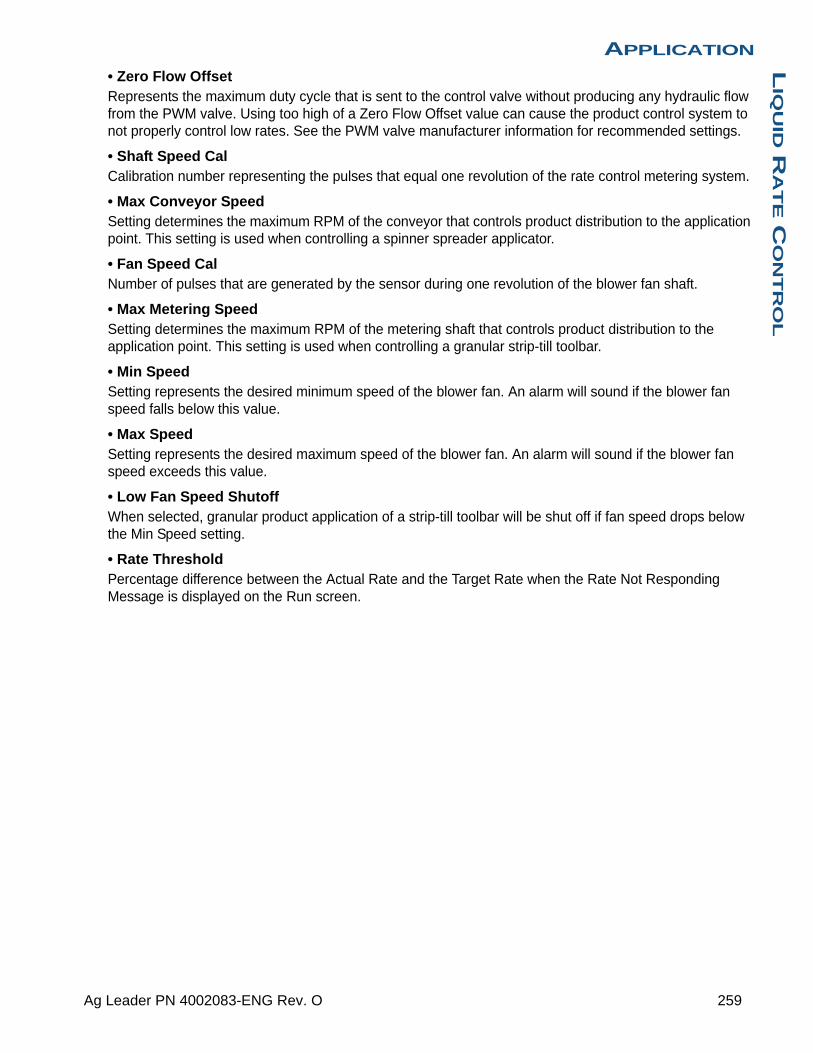
APPLICATIONL
IQU
ID R
AT
E C
ON
TR
OL
• Zero Flow OffsetRepresents the maximum duty cycle that is sent to the control valve without producing any hydraulic flow from the PWM valve. Using too high of a Zero Flow Offset value can cause the product control system to not properly control low rates. See the PWM valve manufacturer information for recommended settings.
• Shaft Speed CalCalibration number representing the pulses that equal one revolution of the rate control metering system.
• Max Conveyor SpeedSetting determines the maximum RPM of the conveyor that controls product distribution to the application point. This setting is used when controlling a spinner spreader applicator.
• Fan Speed CalNumber of pulses that are generated by the sensor during one revolution of the blower fan shaft.
• Max Metering SpeedSetting determines the maximum RPM of the metering shaft that controls product distribution to the application point. This setting is used when controlling a granular strip-till toolbar.
• Min SpeedSetting represents the desired minimum speed of the blower fan. An alarm will sound if the blower fan speed falls below this value.
• Max SpeedSetting represents the desired maximum speed of the blower fan. An alarm will sound if the blower fan speed exceeds this value.
• Low Fan Speed ShutoffWhen selected, granular product application of a strip-till toolbar will be shut off if fan speed drops below the Min Speed setting.
• Rate ThresholdPercentage difference between the Actual Rate and the Target Rate when the Rate Not Responding Message is displayed on the Run screen.
259 Ag Leader PN 4002083-ENG Rev. O

FERTILIZER DEFAULT PRODUCT SETTINGS
Material Type
Abbreviated name for
display and predefined name for
SMS
Percentage (in terms of lbs.100 lbs.)
Density
N P (P2O5) K (K2O)
Anhydrous Ammonia
Liquid under pressure
NH3 82 0 05.14 lbs./gal.
(at 60°F)
28% UAN Liquid 28% UAN 28 0 0 10.67
30% UAN Liquid 30% UAN 30 0 0 10.86 lbs./gal.
32% UAN Liquid 32% UAN 32 0 0 11.06 lbs./gal.
Ammonium polyphosphate (starter)
LiquidAmmonium
polyphosphate
10 34 0 11.73 lbs./gal.
260 Firmware Version 6.3

APPLICATIONIS
OB
US
SE
RIA
L A
PP
LIC
AT
ION
RA
TE C
ON
TR
OL
APPLICATION
ISOBUS SERIAL APPLICATION RATE CONTROL
ENABLE VIRTUAL TERMINAL AND TASK CONTROLLERTo enable the Virtual Terminal:
and
Press: Home button > Setup (wrench) button > Display button > ISOBUS Settings > Enable Virtual Terminal checkbox and Task Controller checkbox
Once a Virtual Terminal has been enabled
will appear in the task bar.
Toggle between the Virtual Terminal run screen and other display functions by pressing the VT button.
Note: The user will have to setup a configuration for the Task Controller also. See “Task Controller” on page 93 for more information on setting up Task Controller configuration.
ISOBUS Settings Enable Virtual Terminal
Enable Task Controller
Virtual Terminal
Enable Virtual Terminal
Broadcast Display Speed
(ISO GBSD)
Auxiliary Module Support
Task Controller
Enable Task Controller
Function Instance
Function Instance
Use 480 Mask Size
0
ISOBUS Settings
0
261 Ag Leader PN 4002083-ENG Rev. O

SETUP
Use drop-down menu to select the System Type
• Sprayer
• Spreader
Use drop-down menu to select Controller Make and Model
Hardi - 5500 (with JobCom)
Bogballe - Calibrator Uniq (Zurf, Uniq, ICON, 2003)
UNIA Group - BREZG
Reco/Sulky - Vision-X
KUHN - Quantron
LH Agro - LH5000
RDS Pro
262 Firmware Version 6.3

APPLICATIONIS
OB
US
SE
RIA
L A
PP
LIC
AT
ION
RA
TE C
ON
TR
OL
Use keyboard to enter the Configuration Name
Use keypad to input the number of sections
263 Ag Leader PN 4002083-ENG Rev. O
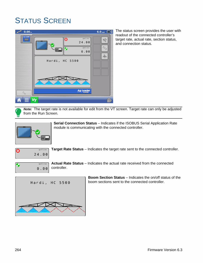
STATUS SCREENThe status screen provides the user with readout of the connected controller’s target rate, actual rate, section status, and connection status.
Note: The target rate is not available for edit from the VT screen. Target rate can only be adjusted from the Run Screen.
Serial Connection Status – Indicates if the ISOBUS Serial Application Rate module is communicating with the connected controller.
Target Rate Status – Indicates the target rate sent to the connected controller.
Actual Rate Status – Indicates the actual rate received from the connected controller.
Boom Section Status – Indicates the on/off status of the boom sections sent to the connected controller.
264 Firmware Version 6.3

APPLICATIONIS
OB
US
SE
RIA
L A
PP
LIC
AT
ION
RA
TE C
ON
TR
OL
SETTINGS SCREEN
MANAGE CONFIGURATIONS
Press Manage Configurations button to edit system configurations.
A user can add, remove, edit, or select an active configuration. The module will save up to 4 configurations.
ALARM SETTINGSPress Alarm Settings button to edit alarm thresholds.
265 Ag Leader PN 4002083-ENG Rev. O

Warning Enabled – With this setting enabled, the user will get a “Rate Not Responding” alarm when the actual rate does not fall within the threshold and timeout settings. The user will not receive an alarm if this setting is disabled.
Rate Not Responding Threshold – This setting defines the percent value the actual rate can be off from the target rate and not trigger the “Rate Not Responding Alarm” alarm.
Rate Not Responding Timeout – This setting defines the amount of time the actual rate can fall outside the Rate Not Responding Threshold without triggering the “Rate Not Responding Alarm” alarm.
DIAGNOSTICSPress Diagnostics button.
Module Diagnostics – Contains module diagnostic information to assist in troubleshooting.
Alarms – Contains any active alarms from the module.
266 Firmware Version 6.3

APPLICATIONIN
JE
CT
ION
APPLICATION
INJECTIONDirectCommand interfaces with the Raven SCS Sidekick™ for complete control over chemical injection applications. The display can support up to four Raven SCS Sidekick™ injection pumps plus a liquid carrier.
CREATE CONFIGURATION
Press: Home button > Setup (wrench) button > Configuration (tractor) button > Configuration tab > Add (+) button > Application button
A wizard will guide you through the process of selecting or creating a vehicle, implement and controllers.
Your Operating Configuration will then be viewable when you start a new Field Operation with the Field Operation Wizard. For more information see “Create Configuration” on page 223.
SETUP CONFIGURATION
Press: Home button > Setup (wrench) button > Configuration (tractor) button > Configuration tab > your specific configuration > Setup (wrench) button > 2 tab >Controller Settings button
The Controller Settings screen appears.
Pump Calibration
• Factory CalibrationThis number is found on the tag of the Digital Pump Speed Sensor. This tag number represents pulses per 10 fluid ounces. Divide the tag number by 10 and enter this number. Once entered, this number should not be changed.
• Perform CalibrationPress the Perform Calibration button to begin the calibration procedure for the Direct Injection pump. The pump will not run until this calibration has been performed. For more information, see “Calibrating an Injection Pump” on page 268.
Rate Response Warning
• Error ThresholdThe user-defined percentage of actual rate error allowed before an alarm sounds.
Configuration Application
ConfigurationSelect Your Specific
Configuration
Controller Settings
Controller Settings
Pump Calibration
Factory Calibration
11 pls/fl oz Perform Calibration
11 pls/fl oz
Rate Response Warning
Error Threshold
Error Delay 5 s
30 %
Flow Monitor Warning
25 %Error
Threshold
Enable Warning
Active Calibration
267 Ag Leader PN 4002083-ENG Rev. O

• Error DelayThe number of seconds that the actual rate falls out of the error threshold before an alarm sounds.
Flow Monitor Warning
• Error ThresholdThe percentage of perceived application error, based on the discharge flow sensor.
• Enable WarningThe Enable Warning check box allows you the option of displaying the Flow Monitor Warning.
Calibrating an Injection Pump
Calibrate the injection pump at the beginning of each season and any time repairs are made.
Press: Home button > Setup (wrench) button > Configuration (tractor) button > Configuration tab > your specific configuration > Setup (wrench) button > 2 tab >Controller Settings button
1. Enter Factory CalibrationBefore entering a Direct Injection Calibration, a Factory Calibration must be entered. If you have not already done so, enter the Factory Calibration Number by pressing the Factory Calibration button. This number is found on the tag of the Digital Pump Speed Sensor. This tag number represents pulses per 10 fluid ounces. Divide the tag number by 10 and enter this number. Once entered, this number should not be changed.
2. Press Perform CalibrationUnderneath Pump Calibration, press the Perform Calibration button.
3. Prime the Direct Injection PumpThe Pump Calibration Wizard appears. Before beginning this calibration procedure, it is recommended that you first prime the Direct Injection pump. Press the Prime button and continue along with the priming procedure as described in “Priming an Injection Pump”, beginning with Step 3 on page 269. After the priming
procedure is finished, you will return to this Pump Calibration Wizard window. Press to continue.
4. Enter the Dispense Amount
Enter the amount that you want dispensed. Press to continue.
5. Acknowledge the Warning
Prepare to catch any product dispensed in an appropriate container. Press to continue.
6. Start CalibrationPress the green-colored START button to begin the calibration procedure. The Pump Calibration Wizard automatically counts up to the amount that you specified in Step 4. The button will turn red and displays STOP while the product is being dispensed. When the procedure is finished, the button will again turn
green. Press to continue.
Note: You may press the Reset button if you wish to start the calibration procedure over.
ConfigurationSelect Your Specific
Configuration
Controller Settings
268 Firmware Version 6.3

APPLICATIONIN
JE
CT
ION
7. Enter Actual Dispense Amount
Enter in the actual amount of the product that was dispensed. Press to continue.
8. Calibration CompleteThe Pump Calibration number appears. The New Injection Pump Calibration Number now appears in the Pump Calibration screen. From this point, you may either:
• Repeat the calibration by pressing the Repeat Calibration button.
• Press to complete the calibration and exit the Pump Calibration Wizard.
9. Calibration Displayed on Controller Settings screen.The new Injection Pump Calibration Number (A) now appears in the Pump Calibration screen.
Priming an Injection Pump
If you are using a Direct Injection configuration, you must prime the Injection Pump each time you flush or refill a tank, or change products. This ensures that air is not in the product lines.
CAUTION: Failure to perform this priming procedure before beginning a Direct Injection application could result in skips at the start of field operations.
1. Press Injection Control buttonTo prime the Injection Pump, first go to the Map screen. Press the Injection button. The Injection button is located at the left-hand side of the Equipment Tab. The Injection Controls screen appears.
2. Press the Prime buttonAt the Injection Controls screen, press the Prime button.
• You may agitate the Direct Injection tank by pressing the Agitate button. Once pressed, this Agitate setting will continue even after the Priming process is finished,
until you press a second time. To determine if a product should be agitated, check the product specifications.
• In order for a Direct Injection tank to agitate the product, you must set the agitator motor switch on Run (which agitates the product continuously) or Pulse (which agitates the product intermittently).
Controller Settings
Pump Calibration
Factory Calibration
11 pls/fl oz Perform Calibration
11 pls/fl oz
Rate Response Warning
Error Threshold
Error Delay 5 s
30 %
Flow Monitor Warning
25 %Error
Threshold
Enable Warning
Active Calibration
Injection
1
Injection Controls
Injection Prime Agitate
269 Ag Leader PN 4002083-ENG Rev. O

3. Acknowledge the WarningA warning appears, stating that you must circulate the product back to the Direct Injection tank.
Acknowledge the warning by pressing .
4. Start Pump and Set Desired SpeedThe Injection Pump Prime screen appears. The countdown time remaining is shown in the black box. The bar underneath turns green when the pump is
operating. Use / to manually increase or
decrease the pump speed.
Note: The recommended priming time is three minutes (3:00), but the routine can be ended at any time by
pressing .
5. Acknowledge the Warning. A warning appears, stating that you must return chemical injection
plumbing to a field-ready state. Acknowledge the warning by pressing .
LOAD CONFIGURATION
Press: Select Event button.
Select a Season, Grower, Farm, and Field on the Management Selection
screen.
For more information, see “Setup Event” on page 45.
RUN CONFIGURATION
Once a configuration has been completed, the Map View button appears at the bottom of the Home screen. Press the Map View button to see the Map screen. The map below is displayed in Zoom to Detail view.
Injection Pump Prime
Use increase/decrease arrows to start pump and set to desired speed.
Time Remaining
Select Event
270 Firmware Version 6.3

APPLICATIONIN
JE
CT
ION
• (A) Mapping Toolbox
• (B) Product Control Toolbox
• (C) Injection Controls button
• (D) NORAC UC5 Boom Height Control Options button
• (E) Section Indicators
• (F) NORAC UC5 Engage button
• (G) AutoSwath
• (H) Master Switch Status (on)
• Injection Controls button (C)The number of direct injection controllers appear within the Injection Control button. This button displays green for each injection module when detecting flow. Press the Injection Controls button to Prime or Agitate the Injection pump.
INJECTION DIAGNOSTICS
The Injection Diagnostics screen provides raw values from sensors verifying that the pump’s output is working. To go to the Injection Diagnostics screen, press on the Device Information button. At the Devices screen, highlight the item marked AL Direct Inject then
press the Diagnostics button. The Injection Diagnostics screen appears. In addition to the Controller’s Name and Serial Number, it provides the following information:
• Digital Pump SpeedDisplays volume information, shown in Hz.
• Analog Pump SpeedDisplays varying voltage as pump speed is increased or decreased.
• Discharge Flow MonitorDisplays information showing that flow is being discharged for every piston stroke.
• Flow/Speed Sensor RatioThe ratio that the system derived for calibration.
TROUBLESHOOTING DIRECT INJECTION CONFIGURATIONS
When controlling a chemical injection pump using the Injection Module PN: 4000896, the configuration requires the use of a Liquid Module PN: 4000394. The injection control is based off of the vehicle that has been configured for the liquid DirectCommand control channel. Once configured, the Injection pump uses the same switch inputs and ground speed input that has been configured for the liquid system.
1
205 +185 - 205165 - 185145 - 165
0 - 145
Rate
Pressure (PSI)
Main:
Agitation:
37
45
Flow:
Container:
12.0 gal/min
793 gal
Mode: Crop Target Height: 12 in Sensitivity: 5
12.0 12.0 15.5 50F
Injection
1
0.49 ac 5.0 mph
15.0015.00
5.0005.000
gal/ac
lb/ac
115
210
30% UAN
N
Controller Name
Serial Number
Digital Pump Speed (Hz)
Analog Pump Speed (V)
Discharge Flow Monitor (Hz)
Flow/Speed Sensor Ratio
Di2008850060
67.07.2
9.9
0.0
Injection Diagnostics
271 Ag Leader PN 4002083-ENG Rev. O
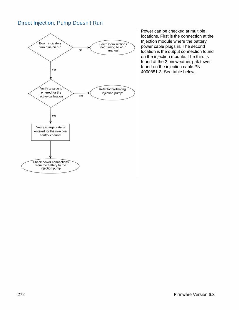
Direct Injection: Pump Doesn’t Run
Power can be checked at multiple locations. First is the connection at the Injection module where the battery power cable plugs in. The second location is the output connection found on the injection module. The third is found at the 2 pin weather-pak tower found on the injection cable PN: 4000851-3. See table below.
Check power connections from the battery to the
injection pump
Refer to “calibrating injection pump”
See “Boom sections not turning blue” in
manual
Verify a target rate is entered for the injection
control channel
Verify a value is entered for the
active calibration
No
Yes
No
Yes
Boom indicators turn blue on run
272 Firmware Version 6.3
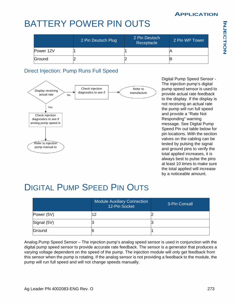
APPLICATIONIN
JE
CT
ION
BATTERY POWER PIN OUTS
Direct Injection: Pump Runs Full Speed
Digital Pump Speed Sensor - The injection pump’s digital pump speed sensor is used to provide actual rate feedback to the display. If the display is not receiving an actual rate the pump will run full speed and provide a “Rate Not Responding” warning message. See Digital Pump Speed Pin out table below for pin locations. With the section valves on the cabling can be tested by pulsing the signal and ground pins to verify the total applied increases, it is always best to pulse the pins at least 10 times to make sure the total applied will increase by a noticeable amount.
DIGITAL PUMP SPEED PIN OUTS
Analog Pump Speed Sensor – The injection pump’s analog speed sensor is used in conjunction with the digital pump speed sensor to provide accurate rate feedback. The sensor is a generator that produces a varying voltage dependent on the speed of the pump. The injection module will only get feedback from this sensor when the pump is rotating. If the analog sensor is not providing a feedback to the module, the pump will run full speed and will not change speeds manually.
2 Pin Deutsch Plug2 Pin Deutsch
Receptacle2 Pin WP Tower
Power 12V 1 1 A
Ground 2 2 B
Module Auxiliary Connection 12-Pin Socket
3-Pin Conxall
Power (5V) 12 2
Signal (5V) 3 3
Ground 6 1
Yes
No
Display receiving actual rate
Check injection diagnostics to see if
anolog pump speed is
Refer to injection pump manual to
Check injection diagnostics to see if
Refer to manufacture
273 Ag Leader PN 4002083-ENG Rev. O

ANALOG SPEED PIN OUTS
Direct Injection: Application Error
The injection module requires that a pump calibration be performed before actual application can occur. The calibration number found on the tag of the injection pump’s digital speed sensor needs to be divided by a factor of 10 before entering it as the factory calibration number. If the factory cal number is entered wrong, the pump calibration routine will not finish due to a high application error.
Notes:
• The pump calibration will fail if error is >10% from the factory calibration number.
• If the calibration fails check pump and plumbing for physical damage or excess wear.
Direct Injection: Discharge Flow Sensor Error
The discharge flow sensor is used as a system check to see if product is actually exiting the output of the pump. The sensor is a shuttle valve that allows feedback for every stroke of the pump. If Flow Monitor Warning is enabled, the display will provide a message if the discharge flow sensor falls out of its calibrated value. See table below for pin locations.
Module Auxiliary Connection 12-Pin Socket
3-Pin Conxall
Signal A>9V at max pump speed
Ground B
Verify factory calibration number is pump cal/10
Refer to injection calibration routine
No
Yes
No
Yes
Status light on run screen showing green
LED light on the injection pump flashing
Check error threshold found in the controller
Check injection diagnostics to see if
Refer to manufacturer documentation to test
274 Firmware Version 6.3

APPLICATIONIN
JE
CT
ION
DISCHARGE FLOW SENSOR PIN OUTS
Direct Injection: Inlet Restriction
The injection pump has a vacuum switch that is used to warn operators of any restriction at the inlet of the pump. The sensor is a normally closed switch that opens if a restriction is encountered in the injection system. A warning will be displayed for the operator if the vacuum switch opens due to restriction. See table below for pin locations. The operator can test the system by unplugging the sensor, which will trigger the warning. If the operator jumps pins A and C, the warning will end.
VACUUM SWITCH PIN OUTS
Controller Settings: Direct Injection Pump CalibrationPump Calibration Setting
• Factory CalibrationThe Factory Calibration Number is found on the tag of the Digital Pump Speed Sensor. This tag number represents pulses per 10 fluid ounces. Divide the tag number by 10 and enter this number. Once entered, this number should not be changed.
• Perform CalibrationPress the Perform Calibration button to begin the calibration procedure for the Direct Injection pump. The pump will not run until this calibration has been performed.
Module Auxiliary Connection 12-Pin Socket
3-Pin WP Shroud
Power (12V) 11 A
Signal 9 B
Ground 8 C
Module Auxiliary Connection 12-Pin Socket
3-Pin WP Shroud
Power (12V) 2 C
Signal 10 A
Make sure 3 way valve is in operate
Check for plugged strainer on the inlet of
Refer to injection pump manual to test vacuum
275 Ag Leader PN 4002083-ENG Rev. O
Rate Response Warning
• Error ThresholdThe user-defined percentage of actual rate error allowed before an alarm sounds.
• Error DelayThe number of seconds that an actual rate falls out of the error threshold before an alarm sounds.
Flow Monitor Warning
• Error ThresholdThe percentage of perceived application error based on the discharge flow sensor.
• Enable WarningThe Enable Warning check box allows you the option of displaying the Flow Monitor Warning.
Field NotesSetting Name and Description
• Auto Generate Application ReportWhen checked, this option will automatically generate the Smart Report each time product application is completed and the Field button is selected.
• Prompt for Field NotesWhen checked, this option will automatically launch the region summary data collection dialog each time a new region is created at the Run screen during application rate control.
• Report Map Appearance- Multi-Color Rate – Select this option to have the Smart Report display the application maps using the
rate legend as displayed on the run screen.
- Single Color Coverage – Select this option to have the Smart Report display single color product coverage maps.
Run Screen• AutoSwathUse to enable/disable automatic control of boom section on/off state based upon field boundaries, prescription files, and previously applied areas.
276 Firmware Version 6.3

APPLICATIONO
PTR
X
APPLICATION
OPTRXOptRx uses sensors, usually mounted on the sprayer’s booms, to assess reflected light to determine plant vigor. It assigns numeric values to the varying levels of vigor to create a Vegetative Index (VI). Using the VI, OptRx calculates nitrogen application rates—taking into consideration the following preferences of the grower and existing traits in the environment:
• Minimum amount of N to be applied
• Maximum amount of N to be applied
• Conditions where no N should be applied
The nitrogen rates created by OptRx can immediately be used to perform a variable rate application based on the needs of the crop.
INSTALLATION
The display supports up to 10 OptRx sensors. For swaths that are 80 feet or larger, five sensors or more should be used. For swaths less than 80 feet, a minimum of three sensors is recommended.
When installing sensor cables, you must install them in the correct order from left to right.
CAUTION: If you do not install the sensors in their proper places, then the map created by the display will not accurately reflect actual field conditions according to row sensor placement.
Checklist• Sensors should be equally spaced apart. Sensors should not be mounted on the ends of the booms.
• Each sensor should be mounted so that it is centered over the top of a crop row.
• Sensor can operate 20 - 50 in. (51 -127 cm) above the crop canopy. Sensors perform best at 30 - 36 in. (76-91 cm).
CREATE CONFIGURATION
For Liquid Application see “Create Configuration” on page 223.
For Granular Application see “Create Configuration” on page 293.
Sensors can also be set up using Serial Control or can be use for site verification.
277 Ag Leader PN 4002083-ENG Rev. O

CROP SENSOR SETUP
The Crop Sensor Setup screen is where you can adjust the rate displayed on the Map screen Equipment Tab’s VI Bar Graph. You can access the Sensor Setup screen in one of two ways:
Press: Home button > Setup (wrench) button > Configuration (tractor) button > Configuration tab > your specific configuration > Setup (wrench) button > Crop Sensor button
Note: You must have a Reference Strip loaded for the Algorithm Settings button to be active. For more information, see “Scan a Reference Strip” on page 281.
Corn Settings
Minimum Rate - lowest amount of nitrogen operator wants applied. If OptRx prescribes a lower rate system will default to the minimum rate.
Maximum Rate - highest amount of nitrogen operator wants applied. If OptRx prescribes a higher rate system will default to the maximum rate.
Rate Increment - increments of rate change. This setting will be in lbs. of N/ac (kg of N/ha).
Economic Optimal Rate - total amount of nitrogen uptake by the plant over the growing season.
N Credits - amount of nitrogen that is available to the plant in the soil from previous year’s crop and fertilizer application.
Pre-Sidedress Rate - amount of nitrogen that has been applied in the current year before sidedressing.
North American Wheat Settings
Minimum Rate - lowest amount of nitrogen operator wants applied. If OptRx prescribes a lower rate system will default to the minimum rate.
Maximum Rate - highest amount of nitrogen operator wants applied. If OptRx prescribes a higher rate system will default to the maximum rate.
Rate Increment - increments of rate change. This setting will be in lbs. of N/ac (kg of N/ha).
Economic Optimal Rate - total amount of nitrogen uptake by the plant over the growing season.
N Credits - amount of nitrogen that is available to the plant in the soil from previous year’s crop and fertilizer application.
Pre-Topdress Rate - amount of nitrogen that has been applied in the current year before topdressing.
Europe Settings
Minimum Rate - lowest amount of nitrogen operator wants applied. If OptRx prescribes a lower rate system will default to the Minimum Rate.
Maximum Rate - highest amount of Nitrogen operator wants applied. If OptRx prescribes a higher rate system will default to the Maximum Rate.
Rate Increment - increments of rate change. This setting will be in lbs. of N/ac (kg of N/ha).
ConfigurationSelect Your Specific
Configuration
Crop Sensor
Corn Settings
North American Wheat Settings
Europe Settings
278 Firmware Version 6.3
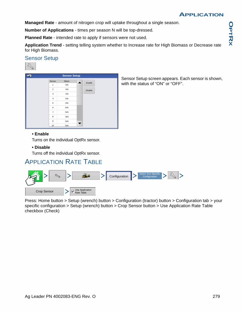
APPLICATIONO
PTR
X
Managed Rate - amount of nitrogen crop will uptake throughout a single season.
Number of Applications - times per season N will be top-dressed.
Planned Rate - intended rate to apply if sensors were not used.
Application Trend - setting telling system whether to Increase rate for High Biomass or Decrease rate for High Biomass.
Sensor Setup
Sensor Setup screen appears. Each sensor is shown, with the status of “ON” or “OFF”.
• EnableTurns on the individual OptRx sensor.
• DisableTurns off the individual OptRx sensor.
APPLICATION RATE TABLE
Press: Home button > Setup (wrench) button > Configuration (tractor) button > Configuration tab > your specific configuration > Setup (wrench) button > Crop Sensor button > Use Application Rate Table checkbox (Check)
Sensor Status
Sensor Setup
1
2
3
4
5
6
7
8
9
10
ON
ON
ON
ON
ON
N/A
Enable
Disable
N/A
N/A
N/A
N/A
ConfigurationSelect Your Specific
Configuration
Crop Sensor Use Application Rate Table
279 Ag Leader PN 4002083-ENG Rev. O
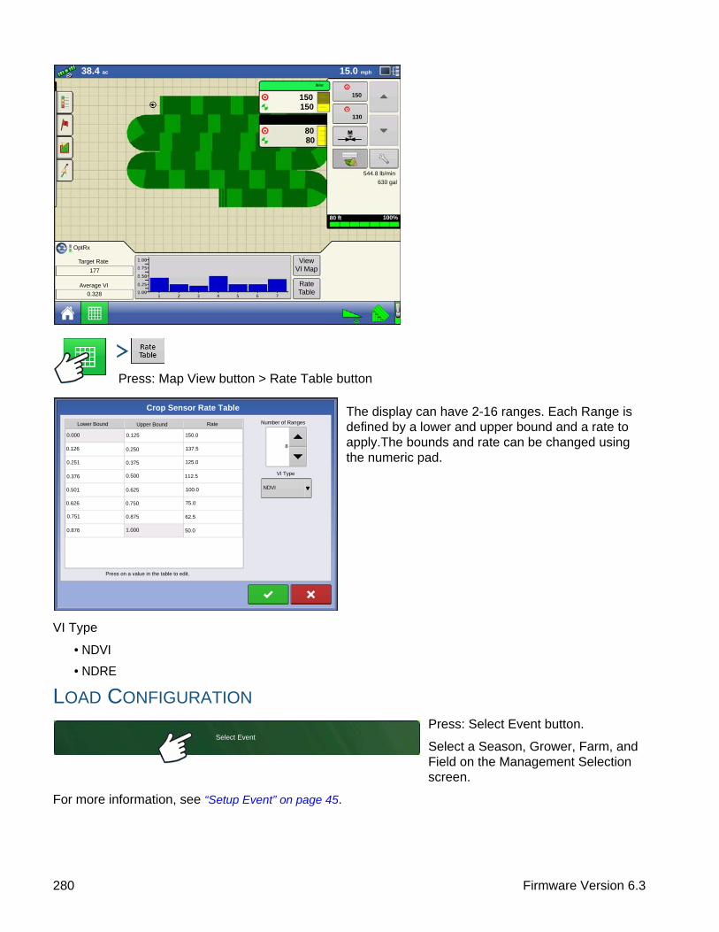
Press: Map View button > Rate Table button
The display can have 2-16 ranges. Each Range is defined by a lower and upper bound and a rate to apply.The bounds and rate can be changed using the numeric pad.
VI Type
• NDVI
• NDRE
LOAD CONFIGURATION
Press: Select Event button.
Select a Season, Grower, Farm, and Field on the Management Selection screen.
For more information, see “Setup Event” on page 45.
80 ft
630 gal
544.8 lb/min
150 150
lb/ac
130
150
15.0 mph38.4 ac
100%
View VI Map
Rate Table
OptRx
Target Rate
177
Average VI
0.328
80 80
lb/ac
Lower Bound
0.125
Crop Sensor Rate Table
Upper Bound Rate
0.000
0.126
0.251
0.376
0.501
0.626
0.751
0.876
0.250
0.375
0.500
0.625
0.750
0.875
1.000
150.0
137.5
125.0
112.5
100.0
75.0
62.5
50.0
Press on a value in the table to edit.
Number of Ranges
8
VI Type
NDVI
Select Event
280 Firmware Version 6.3

APPLICATIONO
PTR
X
RUN CONFIGURATION
Once a configuration has been completed, the Map View button appears at the bottom of the Home screen. Press the Map View button to see the Map screen.
CREATE AN OPTRX V.I. REFERENCE VALUE
Determining where to scan a Reference Strip
In order for the OptRx Crop Sensor Module to recommend an N rate, you must scan a portion of the field to create a V.I. Reference Value.
• CornScan the most vigorous portion of your field for 300 seconds (5 minutes).
• North America WheatScan the most vigorous portion of your field for 300 seconds (5 minutes).
• EuropeScan the portion of your field where the plants show an average amount of vigor and growth. Scan this area for 150 seconds (2.5 minutes).
This V.I. Reference Value is a baseline that the system uses to evaluate the rest of the field.
Scan a Reference Strip
This section describes how to scan a reference strip into the display. This reference strip determines the V.I. Reference Value. It assumes that you have already performed the following tasks:
• Chosen the appropriate part of your field to create a reference strip.
• Created an OptRx module configuration.
• Created a Field Operation Configuration. For more information, see “Management button” on page 30.
1. Press Create Button
Press the Create button, located on the bottom right-hand side of the Map screen’s Equipment Tab.
Note: If a reference strip has already been created, a warning appears, notifying you that this will unload the current reference strip. Press Yes to continue.
2. Enter Reference Strip Information
The Reference Strip Information screen appears. Press to enter the Name, Growth Stage, and
Variety. Press when finished.
3. Drive Reference StripA screen appears, stating that you should drive the applicator to the start of the reference strip. When ready,
press and drive the reference strip.
4. Recording Reference Strip
When you are driving the Reference Strip, appears in the Equipment Tab. This bar
counts the number of seconds that you record the reference strip.
Create
Start
Recording 321
281 Ag Leader PN 4002083-ENG Rev. O

Note: In order to create an accurate Reference Strip, record for at least 300 seconds (5 minutes) in Corn and North American Wheat and 150 seconds (2.5 minutes) in Europe.
5. File NamePress the Stop button when you wish to finish creating the Reference Strip. The Reference Strip Information screen appears, showing the new Reference Strip
file name. Press to accept, or press
to edit, if necessary.
6. OptRx Sensors Apply Variable RateThe OptRx sensors apply variable rate N, based on data received from the sensors. This variable rate appears in the Product Control Toolbox (A).
7. (OPTIONAL) View Reference StripIf desired, you may review this reference strip by pressing the View All button, located on the bottom right-hand side of the Map screen’s Equipment Tab. The file name of the new reference strip appears in the Reference Strip Selection screen.
Note: To delete a reference strip, highlight the file name and press Delete.
CROP SENSOR SETTINGS
Note: All units represent pounds (kilograms) of nitrogen.
205 +185 - 205165 - 185145 - 165
0 - 145
Rate
Flow:
Container:
12.0 gal/min
793 gal
OptRx
0.49 ac 5.0 mph
15.0015.00
5.0005.000
gal/ac 115
210
30% UAN
Target RateN (lb/ac)
50
Average VI0.649
Reference Strip
View All Create
VI MAP
80 ft 0 in 100%
30% UAN
N lb/ac
Reference Strip Select Dialog
DeleteCreate
Sensor Rx:Strip Name:
VI Reference Value:
Field Name:
Crop Growth Stage:
Crop Variety:
Current File Name: 2010-04-20_1516.rfs
Current Strip Name: East Field
File Name
2010-04-19_1009.rfs
2010-04-20_1516.rfs
Mon Apr 19 10:09:28 2012
Tue Apr 20 15:16:56 2012
282 Firmware Version 6.3
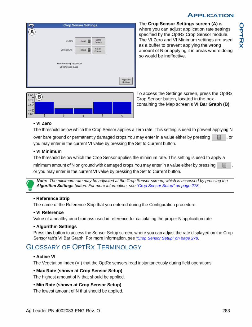
APPLICATIONO
PTR
X
The Crop Sensor Settings screen (A) is where you can adjust application rate settings specified by the OptRx Crop Sensor module. The VI Zero and VI Minimum settings are used as a buffer to prevent applying the wrong amount of N or applying it in areas where doing so would be ineffective.
To access the Settings screen, press the OptRx Crop Sensor button, located in the box containing the Map screen’s VI Bar Graph (B).
• VI ZeroThe threshold below which the Crop Sensor applies a zero rate. This setting is used to prevent applying N
over bare ground or permanently damaged crops.You may enter in a value either by pressing , or
you may enter in the current VI value by pressing the Set to Current button.
• VI MinimumThe threshold below which the Crop Sensor applies the minimum rate. This setting is used to apply a
minimum amount of N on ground with damaged crops.You may enter in a value either by pressing , or you may enter in the current VI value by pressing the Set to Current button.
Note: The minimum rate may be adjusted at the Crop Sensor screen, which is accessed by pressing the Algorithm Settings button. For more information, see “Crop Sensor Setup” on page 278.
• Reference StripThe name of the Reference Strip that you entered during the Configuration procedure.
• VI ReferenceValue of a healthy crop biomass used in reference for calculating the proper N application rate
• Algorithm SettingsPress this button to access the Sensor Setup screen, where you can adjust the rate displayed on the Crop Sensor tab’s VI Bar Graph. For more information, see “Crop Sensor Setup” on page 278.
GLOSSARY OF OPTRX TERMINOLOGY
• Active VIThe Vegetation Index (VI) that the OptRx sensors read instantaneously during field operations.
• Max Rate (shown at Crop Sensor Setup)The highest amount of N that should be applied.
• Min Rate (shown at Crop Sensor Setup)The lowest amount of N that should be applied.
VI Zero:
VI Minimum:
0.000
0.000
Reference Strip: East Field
VI Reference: 0.500
Crop Sensor Settings
Set to Current
Set to Current
Algorithm Settings
283 Ag Leader PN 4002083-ENG Rev. O

• NRefers to Nitrogen being applied.
• N AlgorithmThe OptRx Crop Sensor Module uses an N algorithm to calculate an N rate through a Sufficiency Index reading.
• Rate Increment (shown at Crop Sensor Setup)An optional increment that the display can use to round the N rate applied, if the operator desires. For example, if the operator enters the number 5 and the display is applying a rate of 27, the number will be rounded to 25.
• Reference StripThe healthiest portion of your field where you are satisfied that N is sufficient. This allows a baseline of optimum crop performance that the system can compare against other cropland.
• ReflectanceThe light reading of the plant measured by individual light spectral wavelength. The comparison of different reflectance values can be used to determine the health of the plant.
• VIVegetation Index. The recorded value from remote sensing that displays a comparison of crop vigor and biomass of the scanned plant. This value, which is taken from a reference scan of a Reference Strip, uses a ratio that indicates the health of the plant. NDVI and NDRE are examples of different vegetation indexes.
• VI Minimum (shown at Settings screen)The threshold below which the Crop Sensor applies the minimum rate. This setting is used to apply a minimum amount of N on ground with damaged or diseased crops.
• VI Reference (shown at Settings screen)The value of a healthy crop biomass used in reference for calculating the proper N application rate. The VI Reference value is determined by the creation of a Reference Strip.
• VI Zero (shown at Settings screen)The threshold below which the Crop Sensor applies a zero rate. This setting is used to prevent applying N
over bare ground or permanently damaged crops.
TROUBLESHOOTING OPTRX ERROR MESSAGES
The OptRx Crop Sensors have error messages to inform the user of complications in communication and performance. The following error messages are the most common ones. Follow the recommended troubleshooting steps to correct these errors.
Error Message: “Sensor Lost Communication”Possible Cause: The cabling between the OptRx sensor and the ACS Master Module is
disconnected.
NDVI Normalized Difference Vegetation Index =Near Infared Reflective - Red Reflective
Near Infared Reflective + Red Reflective
NDRE Normalized Difference Red Edge =Near Infared Reflective - Red Edge Reflective
Near Infared Reflective + Red Edge Reflective
284 Firmware Version 6.3

APPLICATIONO
PTR
X
Solution: Check all connections and cables for disconnections, cuts, breaks, or crimps in the line.
Error Message: “Bad Data”Possible Cause: The sensors are either too far from the crop or too close to the crop.
Solution: Adjust the height of the sensor to approximately 30 inches (76 cm.) above the crop canopy by adjusting the boom height or the height on the crop sensor bracket
Error Message: “Sensor Failure”Possible Cause: The sensors are either too far from the crop or too close to the crop.
Solution: Adjust the height of the sensor to approximately 30 inches (76 cm.) above the crop canopy by adjusting the boom height or the height on the crop sensor bracket.
Error Message: “Sensor Failure”Possible Cause: There has been a drop in voltage to the OptRx Crop Sensors.
Solution: Check voltage on the high current power cable to ensure voltage provided to the sensors is approximately 12 V.
Error Message: “Too Few Sensors for Application” Possible Cause: The OptRx configuration must have at least two working sensors to make an N
rate recommendation.1) There has been a drop in voltage to the OptRx Crop Sensors, or
2) The OptRx Crop Sensor is not detecting communication from the OptRx Crop Sensor Module
Solution: Perform the following actions, depending upon the possible cause of the error:If 1), check cabling.
If 2), check the OptRx Diagnostic screen to determine if the OptRx Crop Sensors are still communicating.
285 Ag Leader PN 4002083-ENG Rev. O

286 Firmware Version 6.3
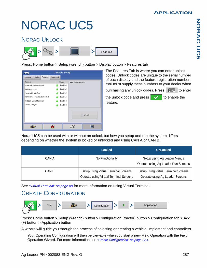
APPLICATIONN
OR
AC
UC
5
APPLICATION
NORAC UC5NORAC UNLOCK
Press: Home button > Setup (wrench) button > Display button > Features tab
The Features Tab is where you can enter unlock codes. Unlock codes are unique to the serial number of each display and the feature registration number. You must supply these numbers to your dealer when
purchasing any unlock codes. Press to enter
the unlock code and press to enable the
feature.
Norac UC5 can be used with or without an unlock but how you setup and run the system differs depending on whether the system is locked or unlocked and using CAN A or CAN B.
See “Virtual Terminal” on page 89 for more information on using Virtual Terminal.
CREATE CONFIGURATION
Press: Home button > Setup (wrench) button > Configuration (tractor) button > Configuration tab > Add (+) button > Application button
A wizard will guide you through the process of selecting or creating a vehicle, implement and controllers.
Your Operating Configuration will then be viewable when you start a new Field Operation with the Field Operation Wizard. For more information see “Create Configuration” on page 223.
Locked UnLocked
CAN A No Functionality Setup using Ag Leader Menus
Operate using Ag Leader Run Screens
CAN B Setup using Virtual Terminal Screens
Operate using Virtual Terminal Screens
Setup using Virtual Terminal Screens
Operate using Ag Leader Screens
Features
Features Advanced
Console Setup
General
Feature
Automatic Swath Control
Multiple Product
Norac UC5 Interface
Fan Frame - Feed Gate Control
Status
Enabled
Enabled
Enabled
Enabled
Feature Description:
Unlock
Enabled
Display
ISOBUS Virtual Terminal
HARDI Sprayer Enabled
Configuration Application
287 Ag Leader PN 4002083-ENG Rev. O
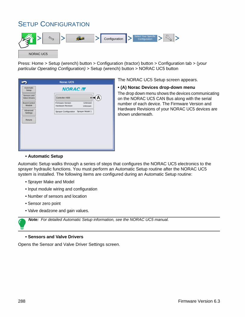
SETUP CONFIGURATION
Press: Home > Setup (wrench) button > Configuration (tractor) button > Configuration tab > (your particular Operating Configuration) > Setup (wrench) button > NORAC UC5 button
The NORAC UC5 Setup screen appears.
• (A) Norac Devices drop-down menuThe drop down menu shows the devices communicating on the NORAC UC5 CAN Bus along with the serial number of each device. The Firmware Version and Hardware Revisions of your NORAC UC5 devices are shown underneath.
• Automatic Setup
Automatic Setup walks through a series of steps that configures the NORAC UC5 electronics to the sprayer hydraulic functions. You must perform an Automatic Setup routine after the NORAC UC5 system is installed. The following items are configured during an Automatic Setup routine:
• Sprayer Make and Model
• Input module wiring and configuration
• Number of sensors and location
• Sensor zero point
• Valve deadzone and gain values.
Note: For detailed Automatic Setup information, see the NORAC UC5 manual.
• Sensors and Valve Drivers
Opens the Sensor and Valve Driver Settings screen.
ConfigurationSelect Your Specific
Configuration
NORAC UC5
Norac UC5
Automatic Setup
Sensors and Valve Drivers
Boom Control Module
Advanced Settings
Retune
Controller #300
Hardware Revision
Firmware Version
Sprayer Configuration Sprayer Model 1
Unknown
Unknown
288 Firmware Version 6.3
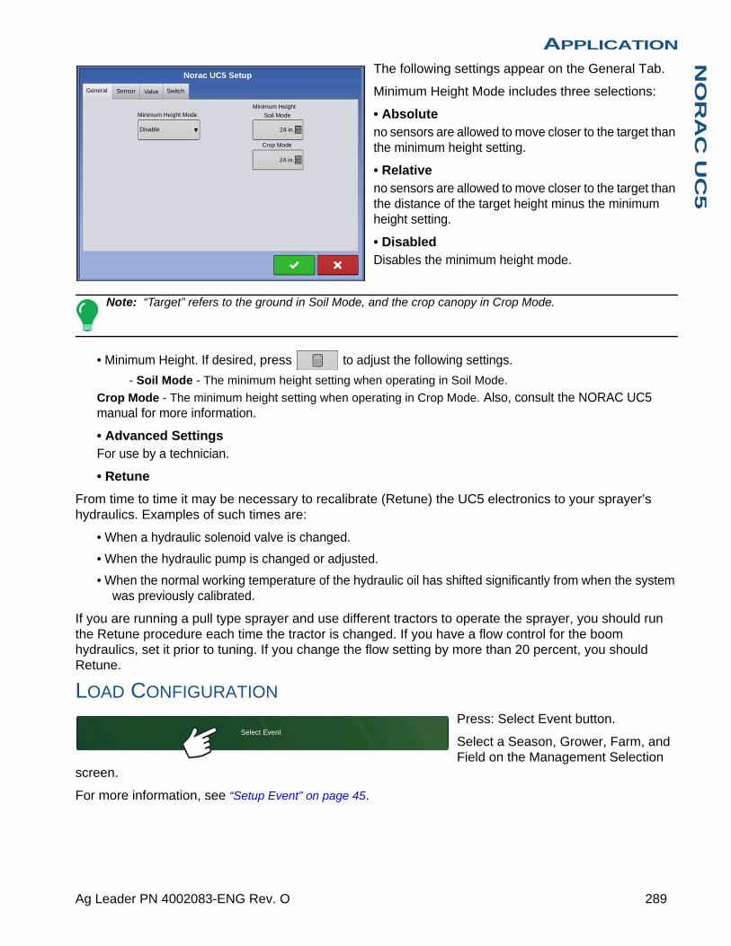
APPLICATIONN
OR
AC
UC
5
The following settings appear on the General Tab.
Minimum Height Mode includes three selections:
• Absoluteno sensors are allowed to move closer to the target than the minimum height setting.
• Relativeno sensors are allowed to move closer to the target than the distance of the target height minus the minimum height setting.
• DisabledDisables the minimum height mode.
Note: “Target” refers to the ground in Soil Mode, and the crop canopy in Crop Mode.
• Minimum Height. If desired, press to adjust the following settings.
- Soil Mode - The minimum height setting when operating in Soil Mode.
Crop Mode - The minimum height setting when operating in Crop Mode. Also, consult the NORAC UC5 manual for more information.
• Advanced SettingsFor use by a technician.
• Retune
From time to time it may be necessary to recalibrate (Retune) the UC5 electronics to your sprayer’s hydraulics. Examples of such times are:
• When a hydraulic solenoid valve is changed.
• When the hydraulic pump is changed or adjusted.
• When the normal working temperature of the hydraulic oil has shifted significantly from when the system was previously calibrated.
If you are running a pull type sprayer and use different tractors to operate the sprayer, you should run the Retune procedure each time the tractor is changed. If you have a flow control for the boom hydraulics, set it prior to tuning. If you change the flow setting by more than 20 percent, you should Retune.
LOAD CONFIGURATION
Press: Select Event button.
Select a Season, Grower, Farm, and Field on the Management Selection
screen.
For more information, see “Setup Event” on page 45.
Norac UC5 Setup
General Sensor Valve Switch
Minimum Height Mode
Disable
Minimum Height
Soil Mode
24 in.
Crop Mode
24 in.
Select Event
289 Ag Leader PN 4002083-ENG Rev. O

RUN CONFIGURATION
Once a configuration has been completed, the Map View button appears at the bottom of the Home screen. Press the Map View button to see the Map screen.
Engage button
If the NORAC UC5 Boom Height Control is included in your Operating Configuration, then the NORAC Engage button appears on the display’s Task Bar. The Engage button enables boom height control. This button is green when the NORAC UC5 system is engaged; and grey when disengaged. Press on this button to engage and disengage the NORAC UC5 Boom Height Control.
This button can be used to toggle back and forth between Automatic Mode and Manual Mode.
• When you enable Automatic Mode, this button turns green and the display beeps three times.
• When you disable Automatic Mode on any part of the boom and the display switches to Manual Mode, this button turns white and the display beeps twice. If less than the full boom remains in Manual Mode, the display will continue beeping twice every three seconds.
Boom Height Control Options Button
At the center of the Map screen’s Equipment Tab, the Boom Height Control Options button displays data on NORAC UC5 Run Time performance.
• The Boom Icon appears as blue when in Automatic Mode; and black when in Manual Mode. The right, left and center sections appear independently on this icon. Press the Boom Height Control Options button to open the Boom Height Control Options screen. For more information, see “Boom Height Control Options Screen” on page 291.
• The white arrows indicate the direction that the boom section is being commanded to move. The arrows shown around the boom appear either 1) In Automatic Mode, or 2) When the boom is in Manual Mode and the boom is moved by the operator.
• ModeIndicates whether the Boom is in Crop Mode or Soil Mode. For further explanation, see “Boom Height Control Options Screen” on page 291.
• Target HeightThe desired boom height above the ground (for Soil Mode), or the crop canopy (for Crop Mode).
• SensitivityAdjusts the boom response. Higher values make the height control more responsive.
• Distance Between Boom and TargetThe numbers that appear below the Boom Icon show the distance between the boom section and the target.
• TemperatureShows the measurement of the outside ambient air temperature.
Mode: Crop Target Height: 12 in Sensitivity: 5
15.9 8.4 8.4 50 F
290 Firmware Version 6.3
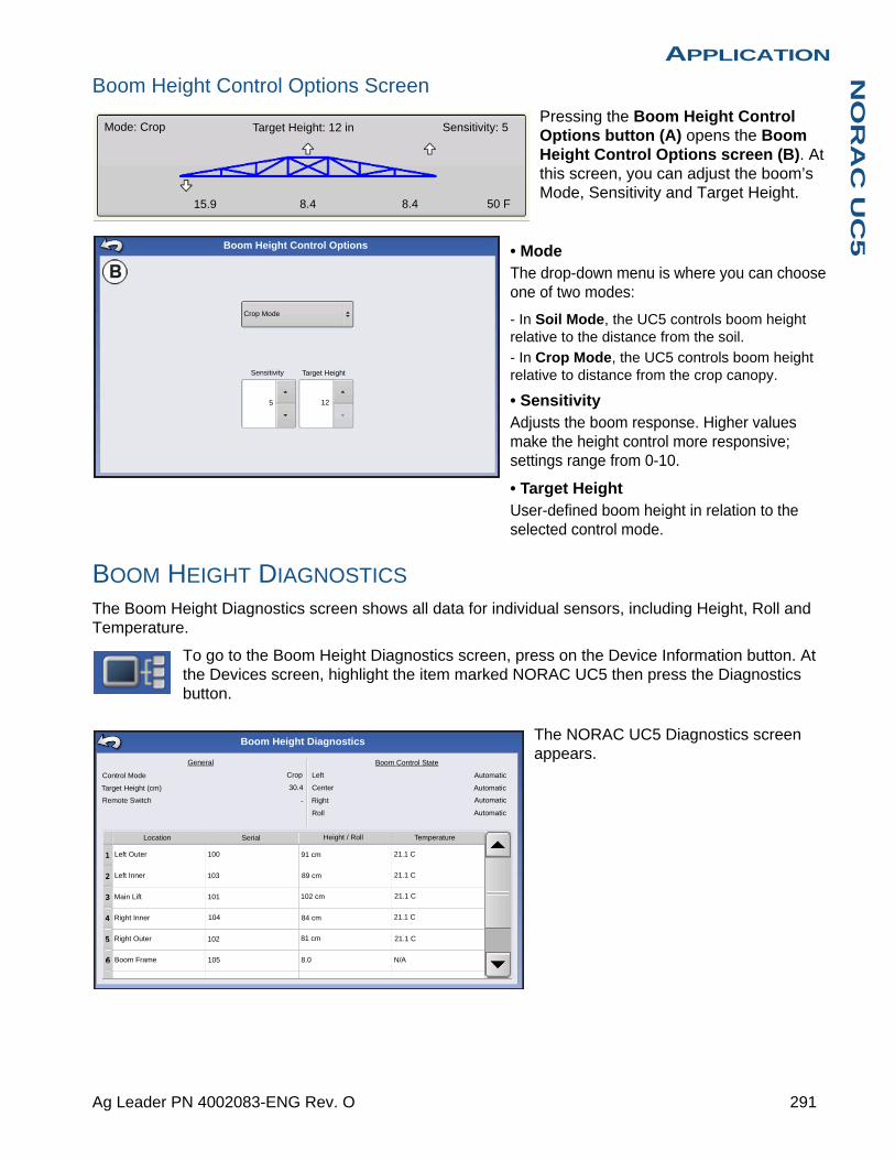
APPLICATIONN
OR
AC
UC
5
Boom Height Control Options Screen
Pressing the Boom Height Control Options button (A) opens the Boom Height Control Options screen (B). At this screen, you can adjust the boom’s Mode, Sensitivity and Target Height.
• ModeThe drop-down menu is where you can choose one of two modes:
- In Soil Mode, the UC5 controls boom height relative to the distance from the soil.
- In Crop Mode, the UC5 controls boom height relative to distance from the crop canopy.
• SensitivityAdjusts the boom response. Higher values make the height control more responsive; settings range from 0-10.
• Target HeightUser-defined boom height in relation to the selected control mode.
BOOM HEIGHT DIAGNOSTICS
The Boom Height Diagnostics screen shows all data for individual sensors, including Height, Roll and Temperature.
To go to the Boom Height Diagnostics screen, press on the Device Information button. At the Devices screen, highlight the item marked NORAC UC5 then press the Diagnostics button.
The NORAC UC5 Diagnostics screen appears.
Mode: Crop Target Height: 12 in Sensitivity: 5
15.9 8.4 8.4 50 F
Boom Height Control Options
Crop Mode
Sensitivity Target Height
5 12
Boom Height Diagnostics
General
Control Mode
Target Height (cm)
Remote Switch
Crop
30.4
1
2
3
Location Serial
100
103
101
91 cm
89 cm
102 cm
Left
Center
Right-
Roll
Automatic
Boom Control State
Height / Roll Temperature
21.1 C
84 cm
8.0
104
102
105 N/A
Automatic
Automatic
Automatic
21.1 C
21.1 C
21.1 C
21.1 C
Left Outer
Left Inner
Main Lift
Right Inner
Right Outer
Boom Frame
4
5
6
81 cm
291 Ag Leader PN 4002083-ENG Rev. O

292 Firmware Version 6.3
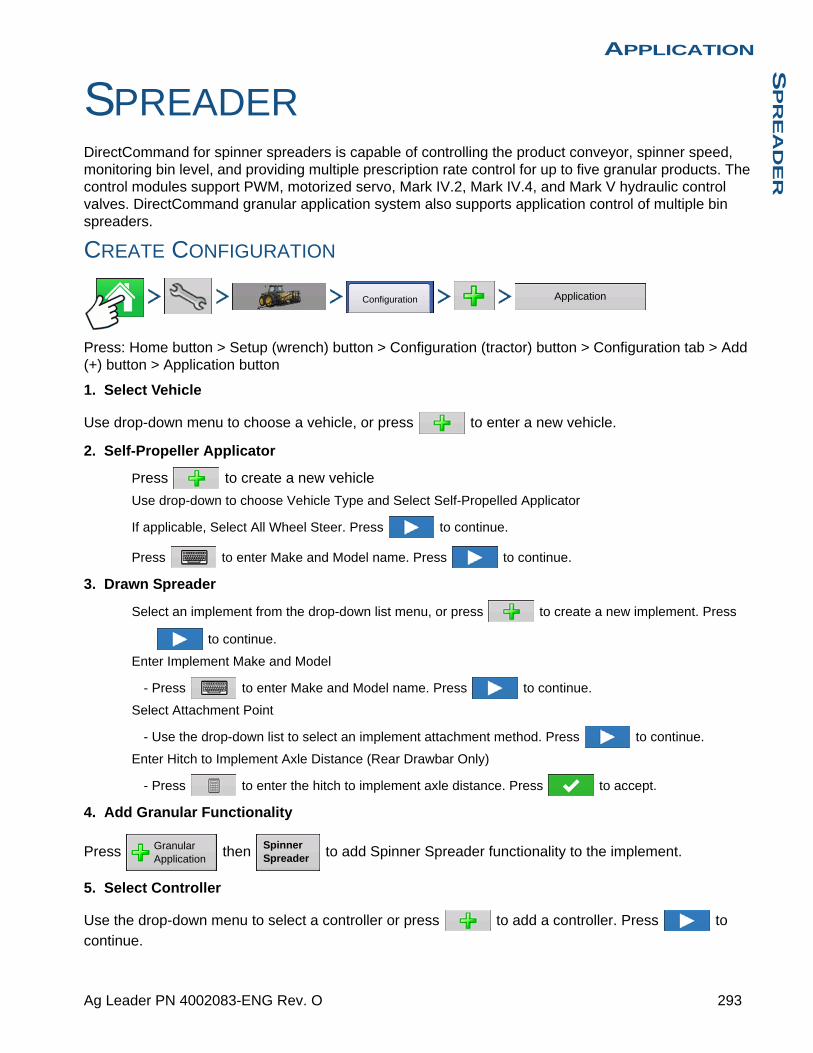
APPLICATIONS
PR
EA
DE
R
APPLICATION
SPREADERDirectCommand for spinner spreaders is capable of controlling the product conveyor, spinner speed, monitoring bin level, and providing multiple prescription rate control for up to five granular products. The control modules support PWM, motorized servo, Mark IV.2, Mark IV.4, and Mark V hydraulic control valves. DirectCommand granular application system also supports application control of multiple bin spreaders.
CREATE CONFIGURATION
Press: Home button > Setup (wrench) button > Configuration (tractor) button > Configuration tab > Add (+) button > Application button
1. Select Vehicle
Use drop-down menu to choose a vehicle, or press to enter a new vehicle.
2. Self-Propeller Applicator
Press to create a new vehicle
Use drop-down to choose Vehicle Type and Select Self-Propelled Applicator
If applicable, Select All Wheel Steer. Press to continue.
Press to enter Make and Model name. Press to continue.
3. Drawn Spreader
Select an implement from the drop-down list menu, or press to create a new implement. Press
to continue.
Enter Implement Make and Model
- Press to enter Make and Model name. Press to continue.
Select Attachment Point
- Use the drop-down list to select an implement attachment method. Press to continue.
Enter Hitch to Implement Axle Distance (Rear Drawbar Only)
- Press to enter the hitch to implement axle distance. Press to accept.
4. Add Granular Functionality
Press then to add Spinner Spreader functionality to the implement.
5. Select Controller
Use the drop-down menu to select a controller or press to add a controller. Press to
continue.
Configuration Application
Granular Application
Spinner Spreader
293 Ag Leader PN 4002083-ENG Rev. O
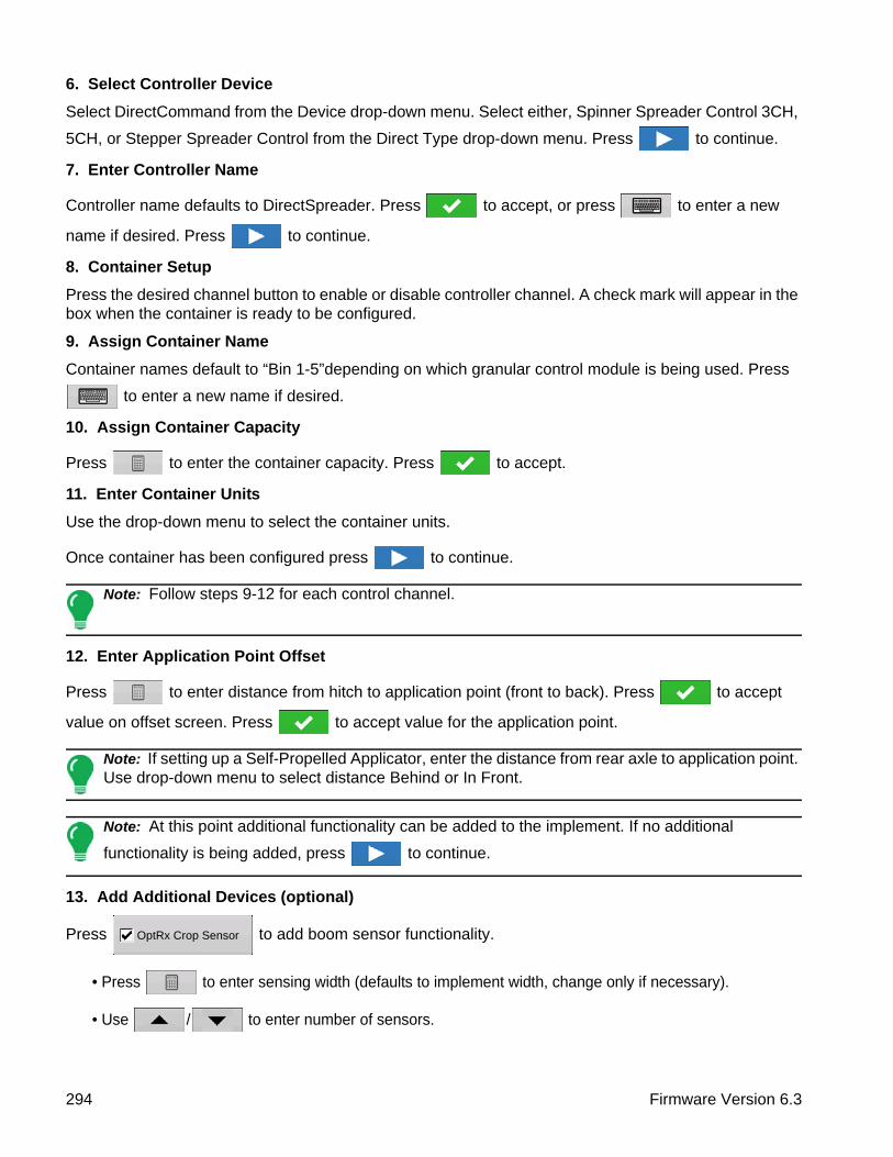
6. Select Controller Device
Select DirectCommand from the Device drop-down menu. Select either, Spinner Spreader Control 3CH,
5CH, or Stepper Spreader Control from the Direct Type drop-down menu. Press to continue.
7. Enter Controller Name
Controller name defaults to DirectSpreader. Press to accept, or press to enter a new
name if desired. Press to continue.
8. Container Setup
Press the desired channel button to enable or disable controller channel. A check mark will appear in the box when the container is ready to be configured.
9. Assign Container Name
Container names default to “Bin 1-5”depending on which granular control module is being used. Press
to enter a new name if desired.
10. Assign Container Capacity
Press to enter the container capacity. Press to accept.
11. Enter Container Units
Use the drop-down menu to select the container units.
Once container has been configured press to continue.
Note: Follow steps 9-12 for each control channel.
12. Enter Application Point Offset
Press to enter distance from hitch to application point (front to back). Press to accept
value on offset screen. Press to accept value for the application point.
Note: If setting up a Self-Propelled Applicator, enter the distance from rear axle to application point. Use drop-down menu to select distance Behind or In Front.
Note: At this point additional functionality can be added to the implement. If no additional
functionality is being added, press to continue.
13. Add Additional Devices (optional)
Press to add boom sensor functionality.
• Press to enter sensing width (defaults to implement width, change only if necessary).
• Use / to enter number of sensors.
OptRx Crop Sensor
294 Firmware Version 6.3
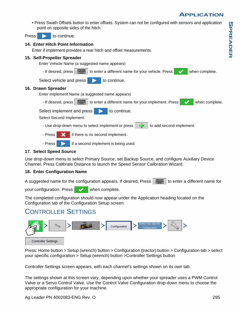
APPLICATIONS
PR
EA
DE
R
• Press Swath Offsets button to enter offsets. System can not be configured with sensors and application point on opposite sides of the hitch.
Press to continue.
14. Enter Hitch Point InformationEnter if implement provides a rear hitch and offset measurements.
15. Self-Propeller SpreaderEnter Vehicle Name (a suggested name appears)
- If desired, press to enter a different name for your vehicle. Press when complete.
Select vehicle and press to continue.
16. Drawn SpreaderEnter Implement Name (a suggested name appears)
- If desired, press to enter a different name for your implement. Press when complete.
Select implement and press to continue.
Select Second Implement.
- Use drop-down menu to select Implement or press to add second implement.
- Press if there is no second implement.
- Press if a second implement is being used.
17. Select Speed Source
Use drop-down menu to select Primary Source, set Backup Source, and configure Auxiliary Device Channel. Press Calibrate Distance to launch the Speed Sensor Calibration Wizard.
18. Enter Configuration Name
A suggested name for the configuration appears. If desired, Press to enter a different name for
your configuration. Press when complete.
The completed configuration should now appear under the Application heading located on the Configuration tab of the Configuration Setup screen.
CONTROLLER SETTINGS
Press: Home button > Setup (wrench) button > Configuration (tractor) button > Configuration tab > select your specific configuration > Setup (wrench) button >Controller Settings button
Controller Settings screen appears, with each channel’s settings shown on its own tab.
The settings shown at this screen vary, depending upon whether your spreader uses a PWM Control Valve or a Servo Control Valve. Use the Control Valve Configuration drop-down menu to choose the appropriate configuration for your machine.
ConfigurationSelect Your Specific
Configuration
Controller Settings
295 Ag Leader PN 4002083-ENG Rev. O
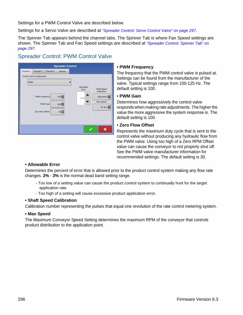
Settings for a PWM Control Valve are described below.
Settings for a Servo Valve are described at “Spreader Control: Servo Control Valve” on page 297.
The Spinner Tab appears behind the channel tabs. The Spinner Tab is where Fan Speed settings are shown. The Spinner Tab and Fan Speed settings are described at “Spreader Control: Spinner Tab” on page 297.
Spreader Control: PWM Control Valve
• PWM FrequencyThe frequency that the PWM control valve is pulsed at. Settings can be found from the manufacturer of the valve. Typical settings range from 100-125 Hz. The default setting is 100.
• PWM GainDetermines how aggressively the control valve responds when making rate adjustments. The higher the value the more aggressive the system response is. The default setting is 100.
• Zero Flow OffsetRepresents the maximum duty cycle that is sent to the control valve without producing any hydraulic flow from the PWM valve. Using too high of a Zero RPM Offset value can cause the conveyor to not properly shut off. See the PWM valve manufacturer information for recommended settings. The default setting is 30.
• Allowable Error Determines the percent of error that is allowed prior to the product control system making any flow rate changes. 2% - 3% is the normal dead band setting range.
- Too low of a setting value can cause the product control system to continually hunt for the target application rate.
- Too high of a setting will cause excessive product application error.
• Shaft Speed Calibration Calibration number representing the pulses that equal one revolution of the rate control metering system.
• Max SpeedThe Maximum Conveyor Speed Setting determines the maximum RPM of the conveyor that controls product distribution to the application point.
Spreader Control
Channel 1 Channel 2
Control Valve Configuration
PWM
Channel 3 Spinner
PWM Frequency
PWM Gain
Zero Flow Offset
Allowable Error Shaft Speed
Calibration
180 pls/rev
Max Speed
60 rpm
296 Firmware Version 6.3

APPLICATIONS
PR
EA
DE
R
Spreader Control: Servo Control Valve• Valve Response 1Determines the speed of the servo valve when product control error exceeds the Response Threshold setting. Represents the fast speed of the servo valve. Decreasing the value will cause the servo valve to run slower. The default setting is 40%.
• Valve Response 2Determines the speed of the servo valve when product control error is less than the Response Threshold setting. Represents the slow speed of the servo valve. Decreasing the value will cause the servo valve to run slower. The default setting is 8%.
• Response ThresholdDetermines where the control channel switches between using Valve Response 1 and Valve Response 2 speed setting. Leaving all other valve control settings at the default value and making a small adjustment to this setting is usually all that is required to fine-tune system performance. The default setting is 15.
- Decreasing this value will have the overall effect of speeding up servo valve response.
- Increasing this value will have the overall effect of slowing servo valve response.
• Allowable Error Determines the percent of error that is allowed prior to the product control system making any flow rate changes. 2% - 3% is the normal dead band setting range.
- Too low of a setting value can cause the product control system to continually hunt for the target application rate.
- Too high of a setting will cause excessive product application error.
• Shaft Speed CalibrationCalibration number representing the pulses that equal one revolution of the rate control metering system.
• Max SpeedThe Maximum Conveyor Speed setting determines the maximum RPM of the conveyor that controls product distribution to the application point.
Spreader Control: Spinner Tab
To view Fan Speed Calibration settings, press the Spinner Tab. Operators with Spinner Spreaders that use PWM valves will see additional active settings.
Spreader Control
Channel 1 Channel 2 Channel 3 Spinner
Control Valve Configuration
Servo
40 % 8 %
15
2 %180 pls/rev
Max Speed
60 rpm
Valve Response 1
Valve Response 2
Response Threshold
Allowable Error Shaft Speed
Calibration
297 Ag Leader PN 4002083-ENG Rev. O

• Fan Speed CalibrationThe number of pulses that are generated by the sensor during one revolution of the spinner dish. The default setting is 4.
• PWM GainDetermines how aggressively the control valve responds when making spinner speed adjustments. The higher the value the more aggressive the system response is. The default setting is 20.
• PWM FrequencyThe frequency that the PWM control valve is pulsed at. Settings can be found from the manufacturer of the valve. Typical settings range from 100-125 Hz. The default setting is 100.
• Zero RPM OffsetRepresents the maximum duty cycle that is sent to the control valve without producing any hydraulic flow from the PWM valve. Using too high of a Zero RPM Offset value can cause the spinner system to not properly shut off. The default setting is 30.
Note: See the PWM valve manufacturer information for recommended settings.
• Automatic ControlChecking this box enables closed loop spinner control.
Beginning with the 5.4 display firmware upgrade, checking the Automatic Control check box exposes a Spinner Icon in the Task Bar that allows user to turn on/off spinners from the Map Screen. Automatic Control default setting is unchecked.
CREATING PRODUCTS
Creating application products including dry fertilizer blends can be completed upon initial setup or from the Product Selection screen of the Field Operation Wizard when starting a field operation.
CREATING SINGLE PRODUCTS
To create a single product, to be added to a blend or to be applied by itself, use the on-screen wizard described in the following steps.
Press: Home button > Setup (wrench) button > Configuration (tractor) button > Product tab > Add (+) button > Application Product button
1. Select Product Type Use drop-down menu to select Product.
Spreader Control
Channel 1 Channel 2 Channel 3 Spinner
Fan Speed Calibration
PWM Gain
PWM Frequency
Zero RPM Offset
Automatic Control
4 pls/rev
20
100 Hz
30
ProductApplication
Product
298 Firmware Version 6.3

APPLICATIONS
PR
EA
DE
R
Press to continue.
2. Select Product UnitsWhen selecting the following fertilizers, use drop-down menu to select the product units:
- Ag Lime
- Pell Lime
- User Defined Lime
- User Defined N-P-K
- User Defined Micronutrient
- Other
Press to continue.
3. Enter Product Name
Default product name appears. Press to enter a new name.
Press to complete product setup or press to return to Configuration Setup screen without
making a change.
Created product should appear under the Application heading located on the Product tab of the Configuration Setup screen.
CREATING DRY FERTLIZER BLENDS
Dry fertilizer blends are set up using the on-screen wizard described in the following steps.
1. Press: Home button > Setup (wrench) button > Configuration (tractor) button > Product tab > Add (+) button > Mix/Blend button
2. From the Type drop-down menu select Dry BlendFrom the Define By drop-down menu select:
• Total amounts - to define blend by amounts going into the bin
• Rate/acre - to define blend by the amounts going on an acre
Press to continue.
3. From drop-drown menu select base units.
Press to continue.
4. Press to start the process of adding components to the blend.
Note: Any liquid herbicides set up within the system can be added to create an impregnated blend product.
5. Select the desired component from the drop-down menu. More than 7 products can be put part of a Mix/Blend but only 7 or fewer can be active at the same time.
A new product can be set up at this time by pressing and following the Product Setup Wizard.
Product Mix / Blend
299 Ag Leader PN 4002083-ENG Rev. O
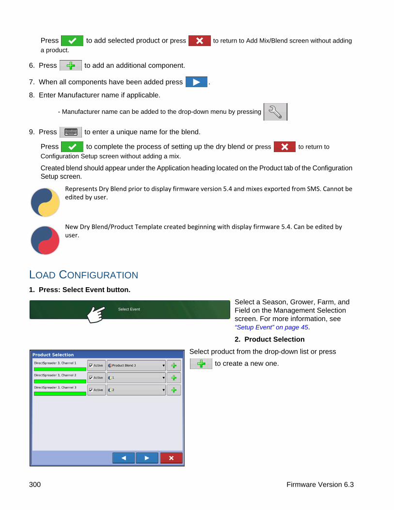
Press to add selected product or press to return to Add Mix/Blend screen without adding
a product.
6. Press to add an additional component.
7. When all components have been added press .
8. Enter Manufacturer name if applicable.
- Manufacturer name can be added to the drop-down menu by pressing
9. Press to enter a unique name for the blend.
Press to complete the process of setting up the dry blend or press to return to
Configuration Setup screen without adding a mix.
Created blend should appear under the Application heading located on the Product tab of the Configuration Setup screen.
Represents Dry Blend prior to display firmware version 5.4 and mixes exported from SMS. Cannot be edited by user.
New Dry Blend/Product Template created beginning with display firmware 5.4. Can be edited by user.
LOAD CONFIGURATION
1. Press: Select Event button.
Select a Season, Grower, Farm, and Field on the Management Selection screen. For more information, see “Setup Event” on page 45.
2. Product Selection
Select product from the drop-down list or press
to create a new one.
Select Event
300 Firmware Version 6.3

APPLICATIONS
PR
EA
DE
R
More than 7 products can be part of a Mix/Blend but 7 or fewer can be active at the same time.
Press to continue.
3. Configure Product Mix
Product Blends can be adjusted after they are created by:
-a.activating or de-activating products
-b.changing rate or total amount of a product
-c.changing total amount of the product or overall rate of product application
These values can be changed on the Configure Product Mix screen which is available in the event setup wizard or by pressing a product line on the home screen.
A product can not be active with a rate of zero.
When all product mixes have been configured press .
4. Select Region and Controlling Product
Select Region from drop-down menu or use press keyboard button to name region.
Select Controlling Product for the Mix/Blend.
Press to complete the process of setting up
the dry blend or press to return to Home screen
without setting up an event.
RUN CONFIGURATION
Once a configuration has been completed, the Map View button appears at the bottom of the Home screen. Press the Map View button to see the Map screen. The map below is displayed in Zoom to Extent view.
Below is an example of a Spinner Spreader Granular Product Control applying two products.
301 Ag Leader PN 4002083-ENG Rev. O

• (A) Mapping Toolbox
• (B) Product Control Toolbox
• (C) Conveyor Indicator
• (D) Settings button (Spreader Control)
• (E) Spinner On/Off
• (F) AutoSwath
• (G) Master Switch Status (on)
AUTOMATIC SPINNER CONTROLTo turn Automatic Control functionality On/Off in the configuration setup see “Automatic Control” on page 298.
Turn Spinners on/off by pressing the Spinner Icon located in the Task Bar. After pressing the Spinner Icon, a warning will appear alerting user the spinners will turn on and to remain clear of equipment.
Press to turn spinners on and clear warning dialog. Press to keep spinners from running and clear warning dialog.
SPINNER SPREADER, WITH TWO-BIN CONFIGURATION
• Settings button (Spreader Control)Press the Settings button to display the Spreader Control screen and settings. These settings include Spread Width, Spinner Speed (if enabled), Product Density, Feed Gate Opening, Conveyor Rate, and Fan Frame (if applicable). For more information, see section beginning at “Spreader Control screen” on page 303.
• Conveyor IndicatorThe Conveyor Indicator is shown at the bottom of the Product Control toolbox when the Map screen is shown in Zoom to Extent. When the Map screen is shown in the Zoom to Details view or Perspective View, the conveyor indicator is shown as a bar that appears behind the vehicle icon.
RUN TIME OPERATIONS
During Run Time Operations, Spinner Spreader operators can press the Settings button to open the Spreader Control screen. At this screen, you can adjust Spread Width, Spinner Speed, Product Density and other settings.
• Each of these settings described below must be set for each individual Product Channel (bin).
Rate
Flow:
Container:
290.6 lb/min
10701 lb
1.19 ac 12.0 mph
lb/acDAP
Potash lb/ac
60 ft 0 in
Fan Frame
Feed Gate
1
DAP
Settings
1 2
302 Firmware Version 6.3
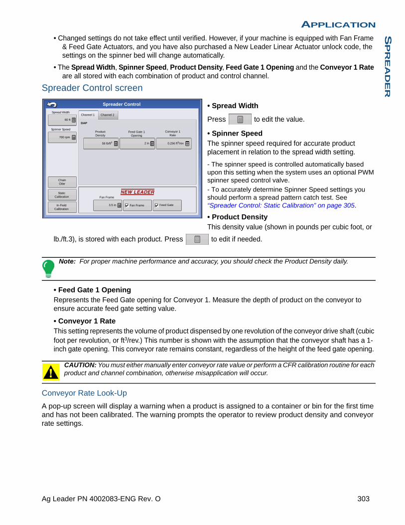
APPLICATIONS
PR
EA
DE
R
• Changed settings do not take effect until verified. However, if your machine is equipped with Fan Frame & Feed Gate Actuators, and you have also purchased a New Leader Linear Actuator unlock code, the settings on the spinner bed will change automatically.
• The Spread Width, Spinner Speed, Product Density, Feed Gate 1 Opening and the Conveyor 1 Rate are all stored with each combination of product and control channel.
Spreader Control screen
• Spread Width
Press to edit the value.
• Spinner SpeedThe spinner speed required for accurate product placement in relation to the spread width setting.
- The spinner speed is controlled automatically based upon this setting when the system uses an optional PWM spinner speed control valve.
- To accurately determine Spinner Speed settings you should perform a spread pattern catch test. See “Spreader Control: Static Calibration” on page 305.
• Product DensityThis density value (shown in pounds per cubic foot, or
lb./ft.3), is stored with each product. Press to edit if needed.
Note: For proper machine performance and accuracy, you should check the Product Density daily.
• Feed Gate 1 OpeningRepresents the Feed Gate opening for Conveyor 1. Measure the depth of product on the conveyor to ensure accurate feed gate setting value.
• Conveyor 1 RateThis setting represents the volume of product dispensed by one revolution of the conveyor drive shaft (cubic foot per revolution, or ft3/rev.) This number is shown with the assumption that the conveyor shaft has a 1-inch gate opening. This conveyor rate remains constant, regardless of the height of the feed gate opening.
CAUTION: You must either manually enter conveyor rate value or perform a CFR calibration routine for each product and channel combination, otherwise misapplication will occur.
Conveyor Rate Look-Up
A pop-up screen will display a warning when a product is assigned to a container or bin for the first time and has not been calibrated. The warning prompts the operator to review product density and conveyor rate settings.
Spreader Control
Channel 1 Channel 2Spread Width
60 ft
Spinner Speed
700 rpm
58 lb/ft3 2 in 0.256 ft3/rev
Product Density
Conveyor 1 Rate
Feed Gate 1 Opening
In-Field Calibration
Static Calibration
Chain Oiler
DAP
Fan Frame
Fan Frame Feed Gate3.5 in
303 Ag Leader PN 4002083-ENG Rev. O
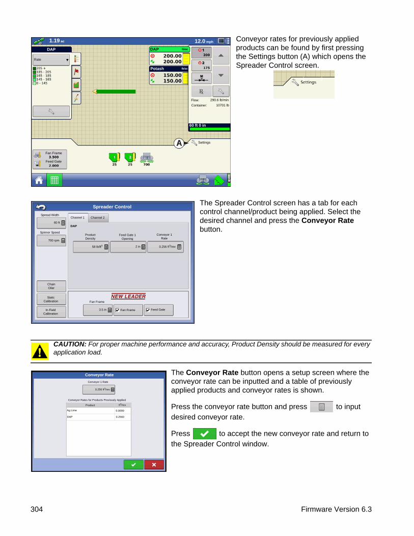
Conveyor rates for previously applied products can be found by first pressing the Settings button (A) which opens the Spreader Control screen.
The Spreader Control screen has a tab for each control channel/product being applied. Select the desired channel and press the Conveyor Rate button.
CAUTION: For proper machine performance and accuracy, Product Density should be measured for every application load.
The Conveyor Rate button opens a setup screen where the conveyor rate can be inputted and a table of previously applied products and conveyor rates is shown.
Press the conveyor rate button and press to input
desired conveyor rate.
Press to accept the new conveyor rate and return to
the Spreader Control window.
Rate
Flow:
Container:
290.6 lb/min
10701 lb
1.19 ac 12.0 mph
lb/acDAP
Potash lb/ac
60 ft 0 in
Fan Frame
Feed Gate
1
DAP
Settings
1 2
Spreader Control
Channel 1 Channel 2Spread Width
60 ft
Spinner Speed
700 rpm
58 lb/ft3 2 in 0.256 ft3/rev
Product Density
Conveyor 1 Rate
Feed Gate 1 Opening
In-Field Calibration
Static Calibration
Chain Oiler
DAP
Fan Frame
Fan Frame Feed Gate3.5 in
Conveyor Rate
Conveyor 1 Rate
0.256 ft3/rev
Conveyor Rates for Products Previously Applied
Product ft3/rev
Ag Lime
DAP
0.0000
0.2560
304 Firmware Version 6.3

APPLICATIONS
PR
EA
DE
R
Fan Frame & Feed Gate Actuator Settings
These are optional settings used by the operators using a New Leader Linear Actuator module and Fan Frame - Feed Gate Control unlock.
• Fan FrameChecking the Fan Frame check box enables the Fan Frame Actuator. Displays the distance between the
spinner bed and the spinner assembly. Press to edit this value.
• Feed GateChecking the Feed Gate check box enables the Feed Gate Actuator.
Spreader Control: Routine Operations
The Spreader Control screen has three buttons, Chain Oiler, Static Calibration and In-Field Calibration, which are described below and on the following pages.
Spreader Control: Chain Oiler
If you are using a Chain Oiler, you can automatically perform a chain oiling routine by pressing the Chain Oiler button on the Spreader Control screen and following the steps below.
Note: Perform a chain oiling routine daily.
1. Press Settings buttonTo begin, press the Settings button to open the Spreader Control screen. At the Spreader Control screen, press the Chain Oiler button.
2. Acknowledge the first warningManually disable or shut off the spinner hydraulic circuit.
3. Enter a Routine DurationEnter the routine time that it takes to turn the conveyor one revolution.
4. Press Start
Press the Start button, and when the routine is finished press .
5. Acknowledge the second warning.Return the spinner hydraulic control to a field-ready condition.
Spreader Control: Static Calibration
You must perform a conveyor discharge calibration for each granular product control channel (bin) for the equipment configuration. This process is outlined below and on the following page. The static calibration procedure is performed before applying in field conditions.
1. Press Settings buttonTo begin, press the Settings button on the Map screen. The Spreader Control screen opens.
2. Start Calibrate Conveyor routinePress the Static Calibration button to start the Static Conveyor Rate calibration routine.
1 2
1 2
305 Ag Leader PN 4002083-ENG Rev. O

3. Disable Spinner Hydraulic Circuit
The system will present a warning to disable the spinner hydraulic circuit. Press after the hydraulic circuit is disabled.
WARNING: Manually disable or shut off the spinner hydraulic circuit. If the spinner runs unexpectedly, injury could occur.
4. Select Conveyor to Calibrate
5. Enter Dispense AmountEnter the desired target amount of product to dispense (the recommended amount is 500 pounds or 250
kilograms). Press to continue.
6. Start Dispensing ProductPress the Start button to begin dispensing the product.
7. Product DispensingThe conveyor will stop when the system perceives the target amount of product has been dispensed. The Stop button can be pressed at any time to manually shut off the conveyor.
8. Product Dispensing StopsOn the screen shown after dispensing the display’s target amount, value can be reset and the process
started again for a larger sample size, if desired. Press to continue.
9. Enter Actual Dispense Amount
Enter the actual weight of the product dispensed. Press to continue.
10. Finish CalibrationA screen displays, stating Calibration Complete and underneath is shown the newly-calibrated conveyor rate.
- Press to exit the calibration without saving the value.
- Press Repeat Calibration to begin the process again.
- Press to save the value and exit the calibration routine.
11. Restart spinner hydraulic circuitRestart the spinner hydraulic circuit.
WARNING: Make sure the spinner is free of material before restarting the spinner hydraulic circuit.
12. A warning will appear when exiting the calibration wizard, instructing you to return the spinner control hydraulic circuit to a field-ready condition.
Spreader Control: In-Field Calibration
The In-Field Conveyor Calibration procedure performs an automated routine to adjust the calibration number for the selected spinner bin. This calibration is performed if there is a difference between the amount of product logged as compared to what was actually applied.
306 Firmware Version 6.3
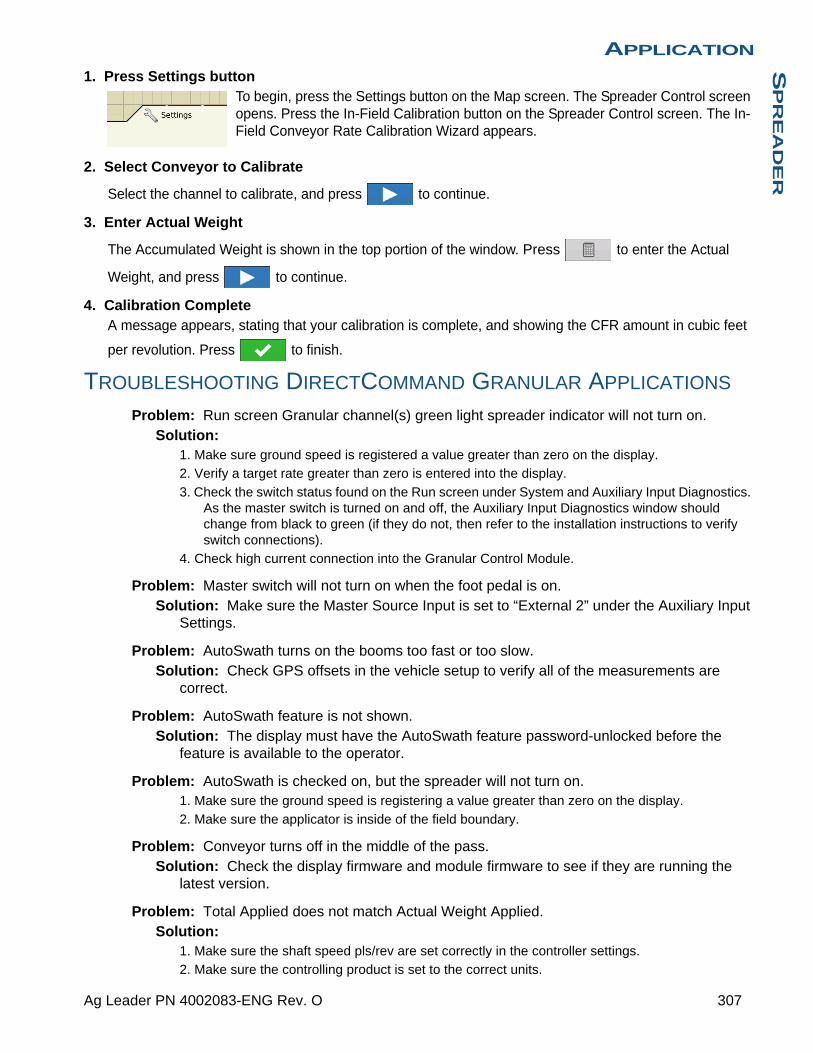
APPLICATIONS
PR
EA
DE
R
1. Press Settings buttonTo begin, press the Settings button on the Map screen. The Spreader Control screen opens. Press the In-Field Calibration button on the Spreader Control screen. The In-Field Conveyor Rate Calibration Wizard appears.
2. Select Conveyor to Calibrate
Select the channel to calibrate, and press to continue.
3. Enter Actual Weight
The Accumulated Weight is shown in the top portion of the window. Press to enter the Actual
Weight, and press to continue.
4. Calibration CompleteA message appears, stating that your calibration is complete, and showing the CFR amount in cubic feet
per revolution. Press to finish.
TROUBLESHOOTING DIRECTCOMMAND GRANULAR APPLICATIONS
Problem: Run screen Granular channel(s) green light spreader indicator will not turn on.Solution:
1. Make sure ground speed is registered a value greater than zero on the display.
2. Verify a target rate greater than zero is entered into the display.
3. Check the switch status found on the Run screen under System and Auxiliary Input Diagnostics. As the master switch is turned on and off, the Auxiliary Input Diagnostics window should change from black to green (if they do not, then refer to the installation instructions to verify switch connections).
4. Check high current connection into the Granular Control Module.
Problem: Master switch will not turn on when the foot pedal is on.Solution: Make sure the Master Source Input is set to “External 2” under the Auxiliary Input
Settings.
Problem: AutoSwath turns on the booms too fast or too slow.Solution: Check GPS offsets in the vehicle setup to verify all of the measurements are
correct.
Problem: AutoSwath feature is not shown.Solution: The display must have the AutoSwath feature password-unlocked before the
feature is available to the operator.
Problem: AutoSwath is checked on, but the spreader will not turn on.1. Make sure the ground speed is registering a value greater than zero on the display.
2. Make sure the applicator is inside of the field boundary.
Problem: Conveyor turns off in the middle of the pass.Solution: Check the display firmware and module firmware to see if they are running the
latest version.
Problem: Total Applied does not match Actual Weight Applied.Solution:
1. Make sure the shaft speed pls/rev are set correctly in the controller settings.
2. Make sure the controlling product is set to the correct units.
1 2
307 Ag Leader PN 4002083-ENG Rev. O
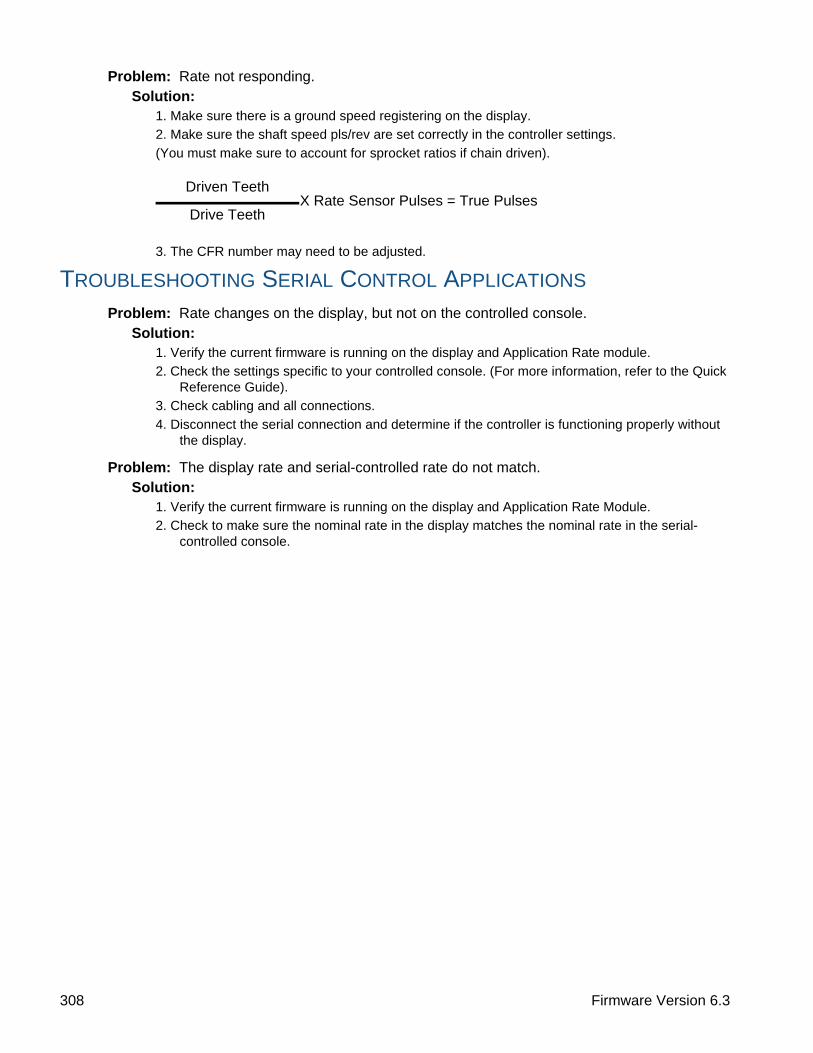
Problem: Rate not responding.Solution:
1. Make sure there is a ground speed registering on the display.
2. Make sure the shaft speed pls/rev are set correctly in the controller settings.
(You must make sure to account for sprocket ratios if chain driven).
3. The CFR number may need to be adjusted.
TROUBLESHOOTING SERIAL CONTROL APPLICATIONS
Problem: Rate changes on the display, but not on the controlled console.Solution:
1. Verify the current firmware is running on the display and Application Rate module.
2. Check the settings specific to your controlled console. (For more information, refer to the Quick Reference Guide).
3. Check cabling and all connections.
4. Disconnect the serial connection and determine if the controller is functioning properly without the display.
Problem: The display rate and serial-controlled rate do not match.Solution:
1. Verify the current firmware is running on the display and Application Rate Module.
2. Check to make sure the nominal rate in the display matches the nominal rate in the serial-controlled console.
Driven TeethX Rate Sensor Pulses = True Pulses
Drive Teeth
308 Firmware Version 6.3
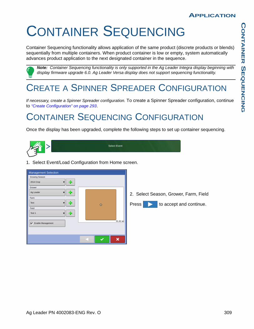
APPLICATIONC
ON
TA
INE
R S
EQ
UE
NC
ING
APPLICATION
CONTAINER SEQUENCINGContainer Sequencing functionality allows application of the same product (discrete products or blends) sequentially from multiple containers. When product container is low or empty, system automatically advances product application to the next designated container in the sequence.
Note: Container Sequencing functionality is only supported in the Ag Leader Integra display beginning with display firmware upgrade 6.0. Ag Leader Versa display does not support sequencing functionality.
CREATE A SPINNER SPREADER CONFIGURATIONIf necessary, create a Spinner Spreader configuration. To create a Spinner Spreader configuration, continue to “Create Configuration” on page 293.
CONTAINER SEQUENCING CONFIGURATIONOnce the display has been upgraded, complete the following steps to set up container sequencing.
1. Select Event/Load Configuration from Home screen.
2. Select Season, Grower, Farm, Field
Press to accept and continue.
Select Event
2014 Crop
Growing Season
Grower
Ag Leader
Farm
Test
Field
Management Selection
Enable Management
Test 1
91.62 ac
309 Ag Leader PN 4002083-ENG Rev. O

3. Press the Add Container Sequence button to add container sequencing to current configuration.
4. Press Container icon to select containers to be sequenced.
Note: System defaults container sequence to ascending order during initial setup. User can select starting container when configuration loads to the Map Screen.
5. Use Sequence Trigger drop-down menu to select container advanced trigger method.
Manual Advance Only - Sequence is manually triggered by user pressing container icon on Map screen.
Low Container Sensor - Sequence automatically advances to next container in the sequence when low container level sensor is uncovered.
Container Low - Sequence automatically advances to next container in the sequence when system reaches low container level alarm countdown set point.
Container Empty - sequence automatically advances to next container in the sequence when container level countdown reaches zero.
Press to accept and continue and return to
the product selection screen on next page.
310 Firmware Version 6.3

APPLICATIONC
ON
TA
INE
R S
EQ
UE
NC
ING
System displays sequenced containers and defaults sequence direction in ascending order.
6. Use drop-down menu to select existing products
or press to add products to active channels.
To create new products see “Creating Products” on page 298.
7. Press to continue to the Event Selection
screen.
8. From the Event Selection screen, Start a new event or select a previous event.
For more details on Events see “Events” on page 26.
9. Press to continue to the Options screen.
10. Use the drop-down menu to select controlling units for products to be applied.
11. Press to accept and continue to Map
screen.
311 Ag Leader PN 4002083-ENG Rev. O
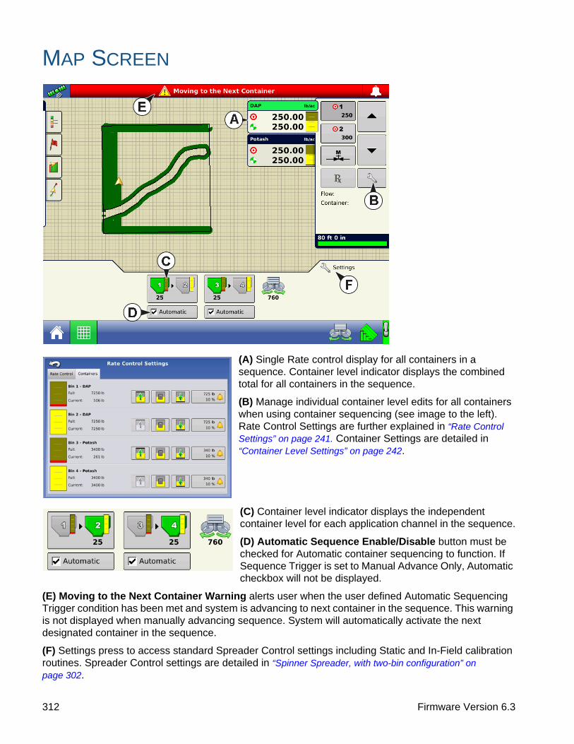
MAP SCREEN
(A) Single Rate control display for all containers in a sequence. Container level indicator displays the combined total for all containers in the sequence.
(B) Manage individual container level edits for all containers when using container sequencing (see image to the left). Rate Control Settings are further explained in “Rate Control Settings” on page 241. Container Settings are detailed in “Container Level Settings” on page 242.
(C) Container level indicator displays the independent container level for each application channel in the sequence.
(D) Automatic Sequence Enable/Disable button must be checked for Automatic container sequencing to function. If Sequence Trigger is set to Manual Advance Only, Automatic checkbox will not be displayed.
(E) Moving to the Next Container Warning alerts user when the user defined Automatic Sequencing Trigger condition has been met and system is advancing to next container in the sequence. This warning is not displayed when manually advancing sequence. System will automatically activate the next designated container in the sequence.
(F) Settings press to access standard Spreader Control settings including Static and In-Field calibration routines. Spreader Control settings are detailed in “Spinner Spreader, with two-bin configuration” on page 302.
312 Firmware Version 6.3

APPLICATIONC
ON
TA
INE
R S
EQ
UE
NC
ING
End of Automatic Container Sequence Warning alerts user the last container in the sequence has met the user defined automatic sequence trigger conditions.
Press to clear warning dialog.
Note: Control Channel will remain active and continue applying.
User must manually reset system to the beginning of the sequence.
The system disables Automatic sequencing. User is required to re-enable Automatic Sequencing for the appropriate container.
To perform calibration procedures, see “Spreader Control: Static Calibration” on page 305 and “Spreader Control: In-Field Calibration” on page 306.
313 Ag Leader PN 4002083-ENG Rev. O

314 Firmware Version 6.3

APPLICATIONS
TR
IP T
ILL
APPLICATION
STRIP TILLDirectCommand for Strip-Till applicators monitors bin level and fan speed sensors, maintains an accurate application rate and supports multiple product prescription rate control for up to three granular products. The Strip Till module supports PWM and Motorized Servo valves as well as Linear Actuator Product Control. System can be configured for Strip Till fertilizer application or Air Seeder (Planting) control. To create an Air Seeder (Planting) configuration continue to “Create Air Seeder Configuration” on page 317.
CREATE STRIP TILL FERTILIZER CONFIGURATION
Press: Home button > Setup (wrench) button > Configuration (tractor) button > Configuration tab > Add (+) button > Application button
A wizard will guide you through the process of selecting or creating a vehicle, implement and controller.
1. Select Vehicle
Use drop-down menu to choose a vehicle, or press to enter a new vehicle. Press to continue.
Note: It is recommended that Vehicle Offset Information be entered before continuing with the configuration process.
2. Select Implement
Select an implement from the drop-down list menu, or press to create a new implement. Press
to continue.
3. Select Implement Attachment Type
Use the drop-down list to select an implement attachment method. Press to continue.
4. Enter Hitch to Implement Axle Distance
Press to enter the hitch to implement axle distance. Press to accept.
5. Add Strip Till Functionality to the Implement
Press then to add Strip Till functionality to the implement.
6. Select Controller
Use the drop-down menu to select controller or press to add a controller. Press to continue.
Configuration Application
Granular Application
Strip Till
315 Ag Leader PN 4002083-ENG Rev. O

7. Select Controller Device
Select DirectCommand from the Device drop-down menu. Select Granular Strip-Till Control from the
Device Type drop-down menu. Press to continue.
8. Enter Controller Name
Controller name defaults to DirectStrip Till. Press to accept, or press to enter a new
name if desired. Press to continue. Press again to continue.
9. Container Setup (Equipment Setup Wizard: Container screen)
Press the desired channel button to enable or disable controller channel. A check mark will appear in the box when the container is ready to be configured.
10. Assign Container Name
Container name defaults to “Bin 1, 2, or 3”. Press to enter a new name if desired.
11. Assign Container Capacity
Use to enter the container capacity. Press to accept.
12. Enter Container Units
Use the drop-down menu to select the container units. Once container has been configured press
to continue.
Note: Follow steps 9-12 for each control channel.
13. Enter Full Swath Width
Full Swath width defaults to a value of 30 ft. Use to enter the full swath width of the implement.
Press to continue.
14. Enter Application Point Offset
Use to enter distance from hitch to application point (front to back). Press to accept.
Note: At this point additional functionality can be added to the implement. If no additional
functionality is being added, press to continue.
15. Add Additional Devices (Optional)
Press OptRx Crop Sensor button to add sensor functionality. Use to enter sensing width. Use
/ to enter number of sensors. Press to continue.
16. Hitch Point Configuration
Press the Implement Provides a Hitch Point button to enter Hitch Point information. Use to enter
Left or Right distance. Use drop-down menu to indicate distance to the left or right. Use to enter
Forward or Backward distance. Press to continue.
316 Firmware Version 6.3
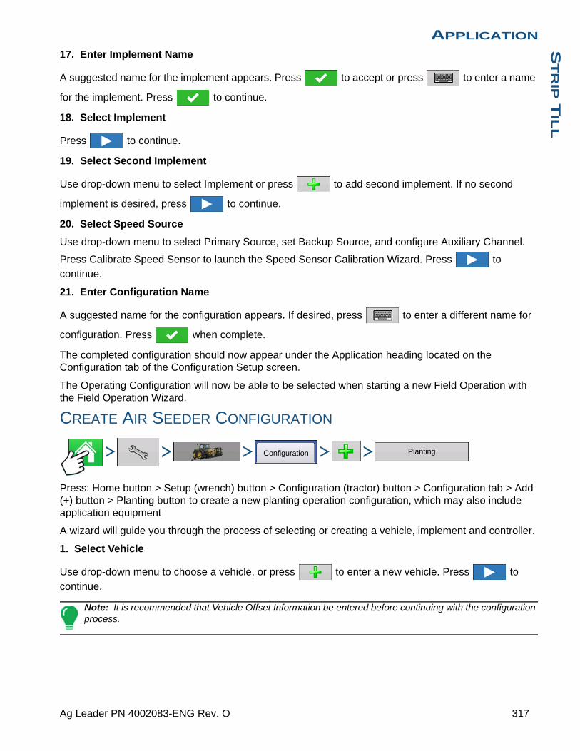
APPLICATIONS
TR
IP T
ILL
17. Enter Implement Name
A suggested name for the implement appears. Press to accept or press to enter a name
for the implement. Press to continue.
18. Select Implement
Press to continue.
19. Select Second Implement
Use drop-down menu to select Implement or press to add second implement. If no second
implement is desired, press to continue.
20. Select Speed Source
Use drop-down menu to select Primary Source, set Backup Source, and configure Auxiliary Channel.
Press Calibrate Speed Sensor to launch the Speed Sensor Calibration Wizard. Press to continue.
21. Enter Configuration Name
A suggested name for the configuration appears. If desired, press to enter a different name for
configuration. Press when complete.
The completed configuration should now appear under the Application heading located on the Configuration tab of the Configuration Setup screen.
The Operating Configuration will now be able to be selected when starting a new Field Operation with the Field Operation Wizard.
CREATE AIR SEEDER CONFIGURATION
Press: Home button > Setup (wrench) button > Configuration (tractor) button > Configuration tab > Add (+) button > Planting button to create a new planting operation configuration, which may also include application equipment
A wizard will guide you through the process of selecting or creating a vehicle, implement and controller.
1. Select Vehicle
Use drop-down menu to choose a vehicle, or press to enter a new vehicle. Press to
continue.
Note: It is recommended that Vehicle Offset Information be entered before continuing with the configuration process.
Configuration Planting
317 Ag Leader PN 4002083-ENG Rev. O

2. Select Implement
Select an implement from the drop-down list menu, or press to create a new implement. Press
to continue.
3. Select Planter/Seeder Type
Use drop-down menu and select Air Seeder from the list. Press to continue.
4. Enter Implement Information
Press and enter implement Make and Model. Press to continue.
5. Select Implement Attachment Type
Use the drop-down list to select an implement attachment method. Press to continue.
6. Enter Distance Application Point Offset
Use to enter distance from hitch to application point (Front to Back). Press to continue.
7. Select Controller
Use the drop-down menu to select controller or press to add a controller. Press to
continue.
8. Select Controller Device and Device Type
Select DirectCommand from the Device drop-down menu. Select Granular Strip-Till Control from the
Device Type drop-down menu. Press to continue.
9. Enter Controller Name
Controller name defaults to Direct Strip Till. Press to accept, or press to enter a new
name if desired. Press to continue.
10. Enter Full Swath Width
Full Swath width defaults to a value of 30 ft. Use to enter the full swath width of the implement.
Press to continue.
11. Select Application Type from the Implement Wizard:Application Channels screen.
Press the Granular Application button.
12. Select Controller
Use the drop-down menu to select same controller as above. Press to continue.
13. Container Setup (Equipment Setup Wizard: Container screen)
Press the desired channel button in order to enable or disable the controller channel. A check mark will appear in the box when the container is ready to be configured.
Note: Channel 1 is automatically assigned as a seeding channel and is intentionally unavailable for user to edit. Proceed with configuration of containers for channels 2 and 3.
318 Firmware Version 6.3

APPLICATIONS
TR
IP T
ILL
14. Assign Container Name
Container name defaults to “Bin 2, or 3”. Press to enter a new name if desired.
15. Assign Container Capacity
Use to enter the container capacity. Press to accept.
16. Enter Container Units
Use the drop-down menu to select the container units. Once container has been configured press
to continue.
Note: Follow steps 13-16 for each control channel.
17. Enter Full Swath Width
Full Swath width defaults to a value of 30 ft. Press to enter the full swath width of the implement.
Press to continue.
18. Enter Application Point Offset
Use to enter distance from hitch to application point (front to back). Press to accept.
Note: At this point additional functionality can be added to the implement. If no additional
functionality is being added, press to continue.
19. Enter Implement Name
A suggested name for the implement appears. Press to accept or press to enter a name
for the implement. Press to continue.
20. Select Implement
Press to continue.
21. Select Speed Source
Use drop-down menu to select Primary Source, set Backup Source, and configure Auxiliary Channel.
Press Calibrate Speed Sensor to launch the Speed Sensor Calibration Wizard. Press to continue.
22. Enter Configuration Name
A suggested name for the configuration appears. If desired, press to enter a different name for
configuration. Press when complete.
The complete configuration should now appear under the Planting heading located on the Configuration tab of the Configuration Setup screen.
The Operating Configuration will now be able to be selected when starting a new Field Operation with the Field Operation Wizard.
319 Ag Leader PN 4002083-ENG Rev. O

CONTROLLER SETTINGS
Press: Home button > Setup (wrench) button > Configuration (tractor) button > Configuration tab > select your specific configuration > Setup (wrench) button >Controller Settings button
Controller Settings screen appears, with each channel’s settings shown on its own tab.
Controller settings viewed at the Strip Till Control window vary depending on Control Valve Configuration type selected including PWM Control Valve, a Servo Control Valve, or a Linear Actuator configuration. Use the Control Valve Configuration drop-down menu to choose the appropriate configuration for your machine. Control valve configuration settings are described in the following section. The Auxiliary Tab allows for adjusting fan settings described at “Strip Till Control: Auxiliary Tab” on page 331.
Strip Till Control: Servo Control Valve
• Valve Response 1Determines the speed of the servo valve when product control error exceeds the Response Threshold setting. Represents the fast speed of the servo valve. Decreasing the value will cause the servo valve to run slower. The default setting is 40%.
• Valve Response 2Determines the speed of the servo valve when product control error is less than the Response Threshold setting. Represents the slow speed of the servo valve. Decreasing the value will cause the servo valve to run slower. The default setting is 8%.
• Response ThresholdDetermines where the control channel switches between using Valve Response 1 and Valve Response 2 speed setting. Leaving all other valve control settings at the default value and making a small adjustment to this setting is usually all that is required to fine tune system performance. The default setting is 15.
- Decreasing this value will have the overall effect of speeding up servo valve response.
- Increasing this value will have the overall effect of slowing servo valve response.
• Allowable Error Determines the percent of error that is allowed prior to the product control system making any flow rate changes. 2% - 3% is the normal dead band setting range.
- Too low of a setting value can cause the product control system to continually hunt for the target application rate.
- Too high of a setting will cause excessive product application error.
• Shaft Speed CalibrationCalibration number representing the pulses that equal one revolution of the rate control metering system.
ConfigurationSelect Your Specific
Configuration
Controller Settings
Channel 1 Channel 2 Channel 3 Auxiliary
Control Valve Configuration
Servo
ValveResponse 1
ValveResponse 2
ResponseThreshold
AllowableError
40 % 8 %
15
2 %
Shaft SpeedCalibration
180 pls/rev
Max MeteringSpeed
100 rpm
Strip Till Control
320 Firmware Version 6.3

APPLICATIONS
TR
IP T
ILL
• Max Metering SpeedSetting determines the maximum RPM of the metering shaft that controls product distribution to the application point. This setting is used when controlling a granular strip-till toolbar.
Strip Till Control: PWM Control Valve
• PWM FrequencyThe frequency that the PWM control valve is pulsed at. Settings can be found from the manufacturer of the valve. Typical settings range from 100-125 Hz. The default setting is 100.
• PWM GainDetermines how aggressively the control valve responds when making rate changes. The higher the value the more aggressive the system response is. The default setting is 100.
• Zero Flow OffsetRepresents the maximum duty cycle that is sent to the control valve without producing any hydraulic flow from
the PWM valve. Using too high of a Zero RPM Offset value can cause the conveyor to not properly shut off. See the PWM valve manufacturer information for recommended settings. The default setting is 30.
• Allowable ErrorDetermines the percent of error that is allowed prior to the product control system making any flow rate changes. 2% - 3% is the normal dead band setting range.
- Too low of a setting value can cause the product control system to continually hunt for the target application rate.
- Too high of a setting will cause excessive product application error.
• Shaft Speed CalibrationCalibration number representing the pulses that equal one revolution of the rate control metering system.
• Max Metering SpeedSetting determines the maximum RPM of the metering shaft that controls product distribution to the application point. This setting is used when controlling a granular strip-till toolbar.
Linear Actuator/Clutch Settings
Note: When using Linear Actuator Control, the system requires the Control Valve Configuration on all three channels to be set the same.
Strip Till Control
Channel 1 Channel 2 Channel 3 Auxiliary
Control Valve Configuration
PWM
PWM Frequency 100
PWM Gain 100
Zero Flow Offset 30
AllowableError
2 %
Shaft SpeedCalibration
180 pls/rev
Max MeteringSpeed
100 rpm
321 Ag Leader PN 4002083-ENG Rev. O

• Actuator Response 1Determines the speed of the actuator when product control error exceeds the Response Threshold setting. Represents the fast speed of the actuator. Decreasing the value will cause the actuator to run slower. The default setting is 90%.
• Actuator Response 2Determines the speed of the actuator when product control error is less than the Response Threshold setting. Represents the slow speed of the actuator. Decreasing the value will cause the actuator to run slower. The default setting is 18%.
• Response ThresholdDetermines where the control channel switches between using Actuator Response 1 and Actuator Response 2 speed settings. Leaving all other actuator control settings at the default value and making a small adjustment to this setting is usually all that is required to fine-tune system performance. The default setting is 4.
- Decreasing this value will have the overall effect of speeding up actuator response.
- Increasing this value will have the overall effect of slowing actuator response.
• Allowable ErrorDetermines the percent of error that is allowed prior to
the product control system making any flow rate changes. 2% - 3% is the normal dead band setting range.
- Too low of a setting value can cause the product control system to continually hunt for the target application rate.
- Too high of a setting will cause excessive product application error.
• Shaft Speed CalCalibration number representing the pulses that equal one revolution of the rate control metering system.
• Max Conveyor SpeedSetting determines the maximum RPM of the conveyor that controls product distribution to the application point.
• Actuator/Clutch ConfigurationSelecting one of the three available actuator/clutch settings: [Single Bin Actuator], [Multiple Bin Actuator, Main Only], [Multiple Bin Actuator, Main + Channel] from the Control Valve Configuration drop-down menu (above) determines specific behavior of the actuators/clutches on zero rate.
Strip Till Control
Channel 1 Channel 2 Channel 3 Auxiliary
Control Valve Configuration
Single Bin Actuator
AllowableError
2 %
Shaft SpeedCalibration
180 pls/rev
Max MeteringSpeed
100 rpm
ActuatorResponse 1
90 %
ActuatorResponse 2
18 %
ResponseThreshold
4
Channel 1 Channel 2 Channel 3
Control Valve Configuration
Auxiliary
Single Bin Actuator
Servo
PWM
Single Ben Actuator
Multiple Bin Actuator, Main Only
Multiple Bin Actuator, Main + Channel
Allowable Error
2 %
Shaft SpeedCalibration
180 pls/rev
Max MeteringSpeed
100 rpm
Strip Till Control
322 Firmware Version 6.3

APPLICATIONS
TR
IP T
ILL
Actuator/Clutch Logic
Determines Actuator/Clutch Behavior on Zero Rate
CREATING DRY FERTLIZER BLENDS
Dry fertilizer blends are set up using the on-screen wizard described in the following steps.
1. Press: Home button > Setup (wrench) button > Configuration (tractor) button > Product tab > Add (+) button > Mix/Blend button
2. From the Type drop-down menu select Dry BlendFrom the Define By drop-down menu select:
• Total amounts - to define blend by amounts going into the bin
• Rate/acre - to define blend by the amounts going on an acre
Press to continue.
3. From drop-drown menu select base units.
Press to continue.
4. Press to start the process of adding components to the blend.
Note: Any liquid herbicides set up within the system can be added to create an impregnated blend product.
5. Select the desired component from the drop-down menu. More than 7 products can be put part of a Mix/Blend but only 7 or fewer can be active at the same time.
A new product can be set up at this time by pressing and following the Product Setup Wizard.
Control Valve Configuration
Control Component State
Control Channel RPM Commanded to Zero Other than
by Master Switch OffMaster Switch Off
Single Bin Actuator
Main Clutch Output = Off
Channel Clutch Output = Off
Linear Actuator = Hold
Main Clutch Output = Off
Channel Clutch Output = Off
Linear Actuator = Hold
Multiple Bin Actuator,
Main Only
Main Clutch Output = On
Channel Clutch Output = Off
Linear Actuator = Close
Main Clutch Output = Off
Channel Clutch Output = Off
Linear Actuator = Hold
Multiple Bin Actuator,
Main + Channel
Main Clutch Output = On
Channel Clutch Output = Off
Linear Actuator = Hold
Main Clutch Output = Off
Channel Clutch Output = Off
Linear Actuator = Hold
Product Mix / Blend
323 Ag Leader PN 4002083-ENG Rev. O
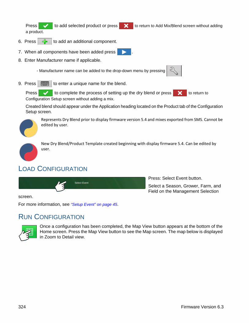
Press to add selected product or press to return to Add Mix/Blend screen without adding
a product.
6. Press to add an additional component.
7. When all components have been added press .
8. Enter Manufacturer name if applicable.
- Manufacturer name can be added to the drop-down menu by pressing
9. Press to enter a unique name for the blend.
Press to complete the process of setting up the dry blend or press to return to
Configuration Setup screen without adding a mix.
Created blend should appear under the Application heading located on the Product tab of the Configuration Setup screen.
Represents Dry Blend prior to display firmware version 5.4 and mixes exported from SMS. Cannot be edited by user.
New Dry Blend/Product Template created beginning with display firmware 5.4. Can be edited by user.
LOAD CONFIGURATION
Press: Select Event button.
Select a Season, Grower, Farm, and Field on the Management Selection
screen.
For more information, see “Setup Event” on page 45.
RUN CONFIGURATION
Once a configuration has been completed, the Map View button appears at the bottom of the Home screen. Press the Map View button to see the Map screen. The map below is displayed in Zoom to Detail view.
Select Event
324 Firmware Version 6.3
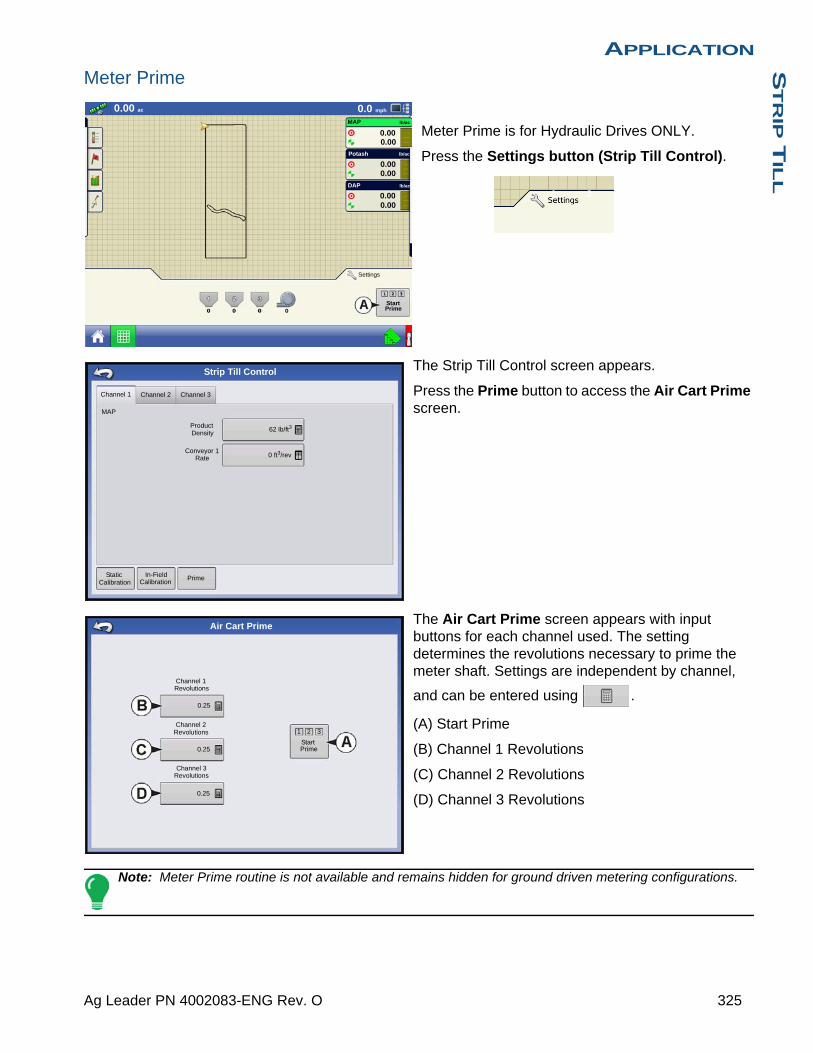
APPLICATIONS
TR
IP T
ILL
Meter Prime
Meter Prime is for Hydraulic Drives ONLY.
Press the Settings button (Strip Till Control).
The Strip Till Control screen appears.
Press the Prime button to access the Air Cart Prime screen.
The Air Cart Prime screen appears with input buttons for each channel used. The setting determines the revolutions necessary to prime the meter shaft. Settings are independent by channel,
and can be entered using .
(A) Start Prime
(B) Channel 1 Revolutions
(C) Channel 2 Revolutions
(D) Channel 3 Revolutions
Note: Meter Prime routine is not available and remains hidden for ground driven metering configurations.
0.00 ac 0.0 mph
0.000.00
0.000.00
0.000.00
MAP
Potash
DAP
lb/ac
lb/ac
lb/ac
StartPrime
Settings
1 2
Channel 1 Channel 2 Channel 3
MAP
ProductDensity
Conveyor 1Rate
62 lb/ft3
0 ft3/rev
StaticCalibration
In-FieldCalibration
Prime
Strip Till Control
Channel 1Revolutions
0.25
Channel 2Revolutions
0.25
Channel 3Revolutions
0.25
1 2 3
StartPrime
Air Cart Prime
325 Ag Leader PN 4002083-ENG Rev. O

The Start Prime button (A) begins the meter prime routine and each meter shaft will rotate the number of revolutions as defined on the Air Cart Prime Screen.
RUN TIME OPERATIONS
During Run Time Operations, Strip Till operators can press the Settings button to open the Strip Till Control screen. At this screen, you can adjust Product Density, Conveyor Rate and other settings.
• Each of these settings described below must be set for each individual Product Channel (bin).
• The Product Density, and the Conveyor 1 Rate are all stored with each combination of product and control channel.
Below is an example of a three channel Strip Till operation setup as a planting configuration.
Strip Till Control
Channel 1 Channel 2 Channel 3 Auxiliary
Control Valve Configuration
Single Bin Actuator
AllowableError
2 %
Shaft SpeedCalibration
180 pls/rev
Max MeteringSpeed
100 rpm
ActuatorResponse 1
90 %
ActuatorResponse 2
18 %
ResponseThreshold
4
0.00 ac 0.0 mph
0.000.00
0.000.00
0.000.00
MAP
Potash
DAP
lb/ac
lb/ac
lb/ac
StartPrime
Settings
1 2
326 Firmware Version 6.3
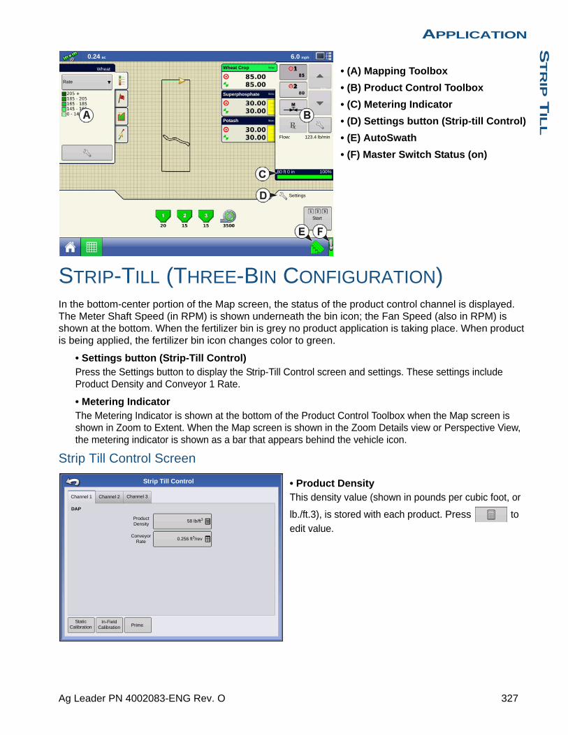
APPLICATIONS
TR
IP T
ILL
• (A) Mapping Toolbox
• (B) Product Control Toolbox
• (C) Metering Indicator
• (D) Settings button (Strip-till Control)
• (E) AutoSwath
• (F) Master Switch Status (on)
STRIP-TILL (THREE-BIN CONFIGURATION)In the bottom-center portion of the Map screen, the status of the product control channel is displayed. The Meter Shaft Speed (in RPM) is shown underneath the bin icon; the Fan Speed (also in RPM) is shown at the bottom. When the fertilizer bin is grey no product application is taking place. When product is being applied, the fertilizer bin icon changes color to green.
• Settings button (Strip-Till Control)Press the Settings button to display the Strip-Till Control screen and settings. These settings include Product Density and Conveyor 1 Rate.
• Metering IndicatorThe Metering Indicator is shown at the bottom of the Product Control Toolbox when the Map screen is shown in Zoom to Extent. When the Map screen is shown in the Zoom Details view or Perspective View, the metering indicator is shown as a bar that appears behind the vehicle icon.
Strip Till Control Screen
• Product DensityThis density value (shown in pounds per cubic foot, or
lb./ft.3), is stored with each product. Press to edit value.
0.24 ac 6.0 mph
Wheat Crop
Potash lb/ac
lb/ac
lb/acSuperphosphate
lb/ac 1
2
123.4 lb/minFlow:
80 ft 0 in 100%
Start
Rate
Wheat
Settings
Channel 1 Channel 2 Channel 3
Prime
58 lb/ft3
0.256 ft3/rev
DAP
Strip Till Control
Product Density
Conveyor Rate
Static Calibration
In-Field Calibration
327 Ag Leader PN 4002083-ENG Rev. O
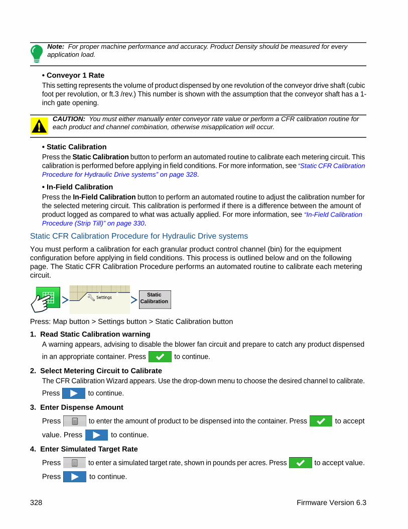
Note: For proper machine performance and accuracy. Product Density should be measured for every application load.
• Conveyor 1 RateThis setting represents the volume of product dispensed by one revolution of the conveyor drive shaft (cubic foot per revolution, or ft.3 /rev.) This number is shown with the assumption that the conveyor shaft has a 1-inch gate opening.
CAUTION: You must either manually enter conveyor rate value or perform a CFR calibration routine for each product and channel combination, otherwise misapplication will occur.
• Static CalibrationPress the Static Calibration button to perform an automated routine to calibrate each metering circuit. This calibration is performed before applying in field conditions. For more information, see “Static CFR Calibration Procedure for Hydraulic Drive systems” on page 328.
• In-Field CalibrationPress the In-Field Calibration button to perform an automated routine to adjust the calibration number for the selected metering circuit. This calibration is performed if there is a difference between the amount of product logged as compared to what was actually applied. For more information, see “In-Field Calibration Procedure (Strip Till)” on page 330.
Static CFR Calibration Procedure for Hydraulic Drive systems
You must perform a calibration for each granular product control channel (bin) for the equipment configuration before applying in field conditions. This process is outlined below and on the following page. The Static CFR Calibration Procedure performs an automated routine to calibrate each metering circuit.
Press: Map button > Settings button > Static Calibration button
1. Read Static Calibration warningA warning appears, advising to disable the blower fan circuit and prepare to catch any product dispensed
in an appropriate container. Press to continue.
2. Select Metering Circuit to CalibrateThe CFR Calibration Wizard appears. Use the drop-down menu to choose the desired channel to calibrate.
Press to continue.
3. Enter Dispense Amount
Press to enter the amount of product to be dispensed into the container. Press to accept
value. Press to continue.
4. Enter Simulated Target Rate
Press to enter a simulated target rate, shown in pounds per acres. Press to accept value.
Press to continue.
1 2 Static Calibration
328 Firmware Version 6.3

APPLICATIONS
TR
IP T
ILL
5. Start Target Rate CountdownPress the start button to begin metering product. The metering circuit will stop automatically when the system perceives the simulated target rate has been dispersed.
As the countdown is started, the button will turn red and state Stop. When the countdown is complete, press
to continue.
6. Enter Actual Dispense AmountEnter the actual dispense amount, in pounds.
Press to continue.
Note: The CFR will be calculated from the actual product amount dispensed.
7. Calibration CompleteA message appears, stating that your calibration is complete, and showing the CFR amount, in cubic feet per revolution. Either:
- Press to exit the calibration without saving the value.
- Press Repeat Calibration to begin the process again.
- Press to save the value and exit the calibration routine.
Static CFR Calibration Procedure for Ground Drive Systems
The Static CFR Calibration Procedure performs an automated routine to calibrate each metering circuit. This calibration is performed before applying in field conditions To perform the Static CFR Calibration, press the Strip Till Control button to open the Strip Till Control screen. At the Strip Till Control screen, the Static Calibration button.
Press: Map button > Settings button > Static Calibration button
1. Read Static Calibration warningA warning appears, advising to disable the blower fan circuit and prepare to catch any product dispensed
in an appropriate container. Press to continue.
2. Select Metering Circuit to CalibrateThe CFR Calibration Wizard appears. Use the drop-down menu to choose the desired channel to calibrate.
Press to continue.
CFR Calibration Wizard: Step 4 of 6
Reset lb
START
1 2 Static Calibration
329 Ag Leader PN 4002083-ENG Rev. O

3. Start Target Rate CountdownPress the Start button and turn drive shaft. The system counts revolutions of the shaft encoder.
Press Stop button in display.
Press to continue.
4. Enter Actual Dispense AmountEnter the actual dispense amount, in pounds.
Press to continue.
Note: The CFR will be calculated from the actual product amount dispensed.
5. Calibration CompleteA message appears, stating that your calibration is complete, and showing the CFR amount, in cubic feet per revolution. Either:
- Press to exit the calibration without saving the value.
- Press Repeat Calibration to begin the process again.
- Press to save the value and exit the calibration routine.
In-Field Calibration Procedure (Strip Till)
The In-Field CFR Calibration procedure performs an automated routine to adjust the calibration number for the selected metering circuit. This calibration is performed if there is a difference between the amount of product logged as compared to what was actually applied. To do an In-Field Calibration procedure, press the In-Field Calibration button on the Strip-Till Control screen, and the In-Field CFR Calibration Wizard appears.
1. Select Metering Circuit to Calibrate
Use the drop-down menu to select the channel to calibrate, and press to continue.
2. Enter Actual Weight
The Accumulated Weight is shown in the top portion of the screen. Press to enter the Actual
Weight, and press to continue.
3. Calibration CompleteA message appears, stating that your calibration is complete, and showing the CFR amount, in cubic feet
per revolution. Press to finish the calibration.
CFR Calibration Wizard: Steps 4 of 6
Revs
START
Press Start before dispensing product. Press Stop when finished dispensing.
330 Firmware Version 6.3

APPLICATIONS
TR
IP T
ILL
Strip Till Control: Auxiliary Tab
• Fan Speed CalNumber of pulses that are generated by the sensor during one revolution of the blower fan shaft.
• Min SpeedSetting represents the desired minimum speed of the blower fan. An alarm will sound if the blower fan speed falls below this value.
• Max SpeedSetting represents the desired maximum speed of the blower fan. An alarm will sound if the blower fan speed exceeds this value.
• Rate ThresholdPercentage difference between the Actual Rate and the Target Rate when the Rate Not Responding Message is displayed on the Run screen.
• Low Fan Speed ShutoffWhen selected, granular product application of a strip-till toolbar will be shut off if fan speed drops below the Min Speed setting.
TROUBLESHOOTING DIRECTCOMMAND GRANULAR APPLICATIONS
Problem: Run screen Granular channel(s) green light spreader indicator will not turn onSolution:
1. Make sure ground speed is registered a value greater than zero on the display.
2. Verify a target rate greater than zero is entered into the display.
3. Check the switch status found on the Run screen under System and Input Diagnostics. As the master switch is turned on and off, the Input Diagnostics window should change from black to green (if they do not, then refer to the installation instructions to verify switch connections).
4. Check high current connection into the Granular Control Module.
Problem: Master switch will not turn on when the foot pedal is on.Solution: Make sure the Master Switch Input is set to “External 2” under the Auxiliary Input
Settings.
Problem: AutoSwath turns on the booms too fast or too slow.Solution: Check GPS offsets in the vehicle setup to verify all of the measurements are
correct.
Problem: AutoSwath feature is not shownSolution: The display must have the AutoSwath feature password-unlocked before the
feature is available to the operator.
Problem: AutoSwath is checked on, but the spreader will not turn on.1. Make sure the ground speed is registering a value greater than zero on the display.
2. Make sure the applicator is inside of the field boundary.
Problem: Conveyor turns off in the middle of the passSolution: Check the display firmware and module firmware to see if they are running the
latest version.
Channel 1 Channel 2 Channel 3 Auxiliary
Fan
Fan Speed Cal
Min Speed
Max Speed Rate Not Responding Threshold
Rate Threshold 30 %
Low Fan Speed Shutoff
Strip Till Control
4 pls/rev
0 rpm
6000 rpm
331 Ag Leader PN 4002083-ENG Rev. O
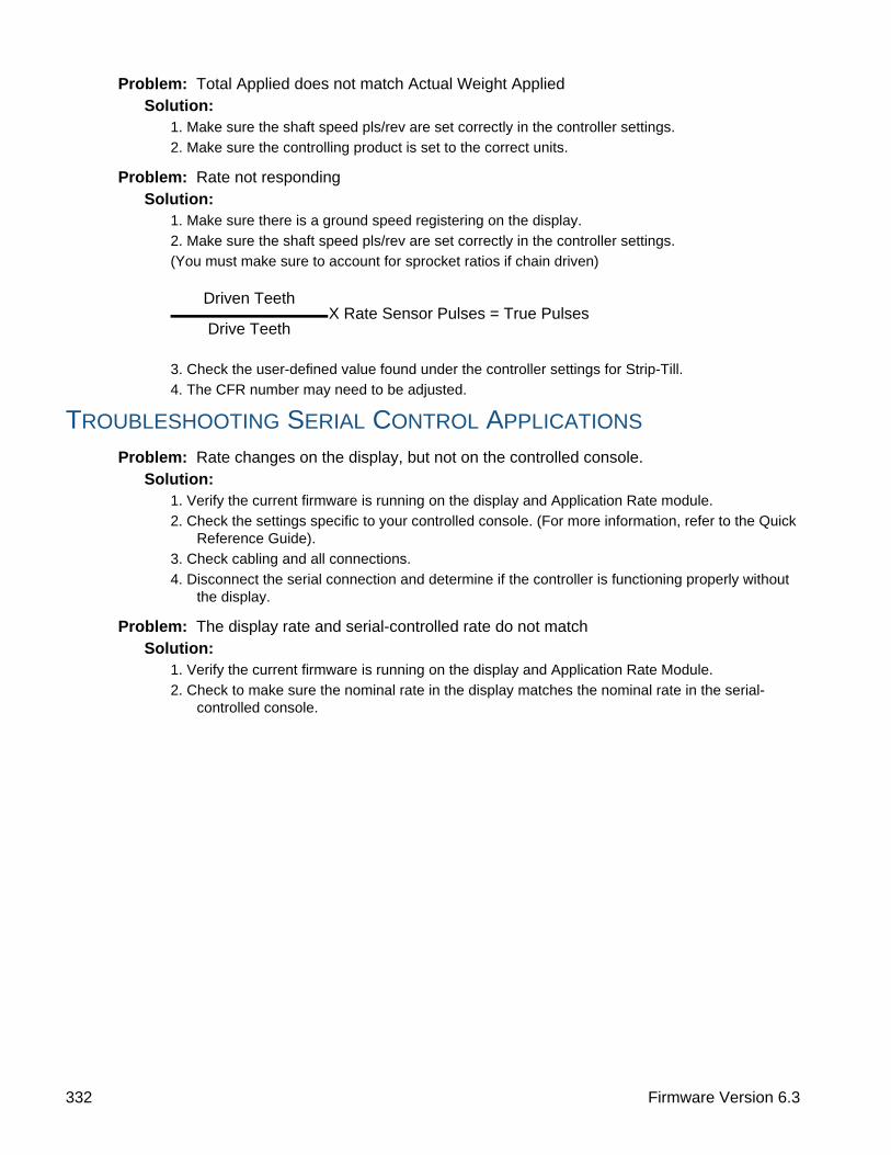
Problem: Total Applied does not match Actual Weight AppliedSolution:
1. Make sure the shaft speed pls/rev are set correctly in the controller settings.
2. Make sure the controlling product is set to the correct units.
Problem: Rate not respondingSolution:
1. Make sure there is a ground speed registering on the display.
2. Make sure the shaft speed pls/rev are set correctly in the controller settings.
(You must make sure to account for sprocket ratios if chain driven)
3. Check the user-defined value found under the controller settings for Strip-Till.
4. The CFR number may need to be adjusted.
TROUBLESHOOTING SERIAL CONTROL APPLICATIONS
Problem: Rate changes on the display, but not on the controlled console.Solution:
1. Verify the current firmware is running on the display and Application Rate module.
2. Check the settings specific to your controlled console. (For more information, refer to the Quick Reference Guide).
3. Check cabling and all connections.
4. Disconnect the serial connection and determine if the controller is functioning properly without the display.
Problem: The display rate and serial-controlled rate do not matchSolution:
1. Verify the current firmware is running on the display and Application Rate Module.
2. Check to make sure the nominal rate in the display matches the nominal rate in the serial-controlled console.
Driven TeethX Rate Sensor Pulses = True Pulses
Drive Teeth
332 Firmware Version 6.3

APPLICATIONS
TR
IP T
ILL
FERTILIZER DEFAULT PRODUCT SETTINGS
Material Type
Abbreviated name for
display and predefined name for
SMS
Percentage (in terms of lbs.100 lbs.)
Density
N P (P2O5) K (K2O)
Ammonium nitrate
DryAmmonium
nitrate34 0 0 N/A
Ammonium phosphate
DryAmmonium phosphate
10 34 0 N/A
DAP Dry DAP 18 46 0 N/A
MAP Dry MAP 11 52 0 N/A
Ammonium sulfate
DryAmmonium
sulfate21 0 0 N/A
Urea Dry Urea 46 0 0 N/A
Potash Dry Potash 0 0 60 N/A
Triple superphosph
ateDry
Triple superphosph
ate0 46 0 N/A
Ordinary superphosph
ateDry
Superphosph
ate0 20 0 N/A
Potassium nitrate
DryPotassium
nitrate13 0 44 N/A
333 Ag Leader PN 4002083-ENG Rev. O

334 Firmware Version 6.3

HARVESTH
AR
VE
ST M
ON
ITO
RIN
G/M
AP
PIN
G
HARVEST
HARVEST
HARVEST MONITORING/MAPPINGDISPLAY PREPARATION
• Create a backup of your spring information. Go to the Setup/Display menu to create a backup. Select Copy All Files to save the spring data to the USB Flash Drive.
• Make sure your display firmware and all connected modules are up to date.
• If you have purchased a new combine or new heads, create new configurations for any setup that is different from last fall. Remove all old configurations.
VEHICLE INSPECTION
• Check to make sure all cables are properly attached and in good condition.
• Remove flow sensor and inspect for damage.
• Check the elevator deflector and impact plate for wear. Verify you have the proper clearance at the top of the clean grain elevator. Clearance should be between 3/8” and 5/8” (0.95 cm to 1.59 cm).
CREATE CONFIGURATION
Press: Home button > Setup (wrench) button > Configuration (tractor) button > Configuration tab > Add (+) button > Harvest button
A wizard will guide you through the process of selecting or creating a configuration that includes Combine, Header and Crops settings.
Your Operating Configuration will then be viewable when you start a new Field Operation with the Field Operation Wizard. For more information on Field Operation Configurations, see “Setup Event” on page 45.
Note: You can also use the Manage Equipment button to create or edit specific vehicles and implements.
CONFIGURATION SETUP
Calibration Sequence
Perform Harvest Calibrations in the following order:
1. Distance (Speed Sensor) CalibrationThis calibrates the Ground Speed Sensor connected to the display. (calibrate a backup sensor even when using GPS speed as the primary speed sensor). For more information, see “Calibrate Distance” on page 81.
2. Calibrate Header SensorThis sets the height when the display stops recording area as the header is raised at the end of the pass. Stop height calibration is required for each grain type.
Configuration Harvest
335 Ag Leader PN 4002083-ENG Rev. O
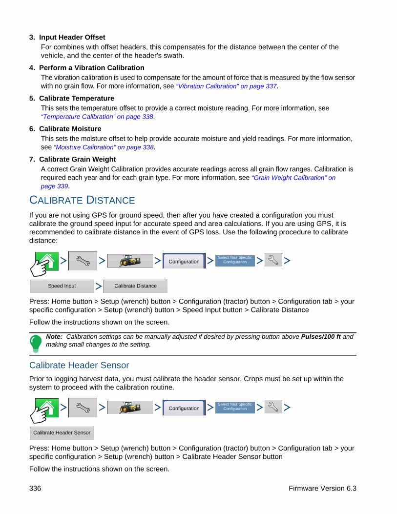
3. Input Header OffsetFor combines with offset headers, this compensates for the distance between the center of the vehicle, and the center of the header's swath.
4. Perform a Vibration CalibrationThe vibration calibration is used to compensate for the amount of force that is measured by the flow sensor with no grain flow. For more information, see “Vibration Calibration” on page 337.
5. Calibrate TemperatureThis sets the temperature offset to provide a correct moisture reading. For more information, see “Temperature Calibration” on page 338.
6. Calibrate MoistureThis sets the moisture offset to help provide accurate moisture and yield readings. For more information, see “Moisture Calibration” on page 338.
7. Calibrate Grain WeightA correct Grain Weight Calibration provides accurate readings across all grain flow ranges. Calibration is required each year and for each grain type. For more information, see “Grain Weight Calibration” on page 339.
CALIBRATE DISTANCE
If you are not using GPS for ground speed, then after you have created a configuration you must calibrate the ground speed input for accurate speed and area calculations. If you are using GPS, it is recommended to calibrate distance in the event of GPS loss. Use the following procedure to calibrate distance:
Press: Home button > Setup (wrench) button > Configuration (tractor) button > Configuration tab > your specific configuration > Setup (wrench) button > Speed Input button > Calibrate Distance
Follow the instructions shown on the screen.
Note: Calibration settings can be manually adjusted if desired by pressing button above Pulses/100 ft and making small changes to the setting.
Calibrate Header Sensor
Prior to logging harvest data, you must calibrate the header sensor. Crops must be set up within the system to proceed with the calibration routine.
Press: Home button > Setup (wrench) button > Configuration (tractor) button > Configuration tab > your specific configuration > Setup (wrench) button > Calibrate Header Sensor button
Follow the instructions shown on the screen.
ConfigurationSelect Your Specific
Configuration
Speed Input Calibrate Distance
ConfigurationSelect Your Specific
Configuration
Calibrate Header Sensor
336 Firmware Version 6.3
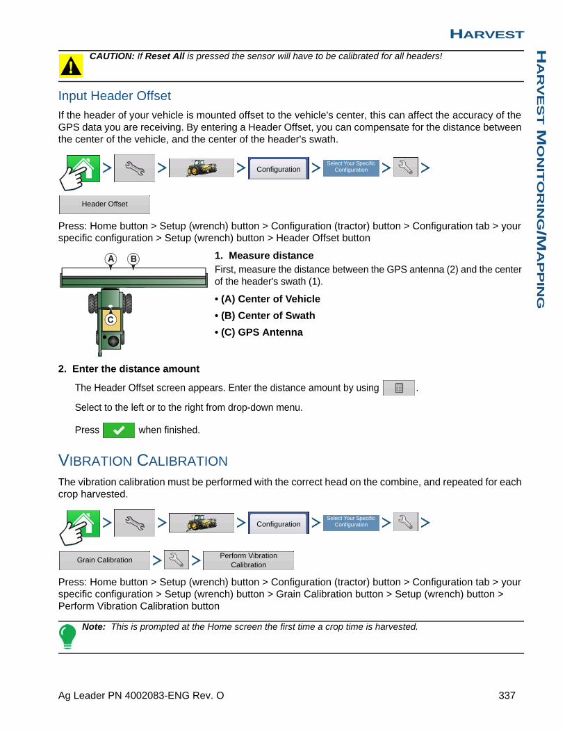
HARVESTH
AR
VE
ST M
ON
ITO
RIN
G/M
AP
PIN
G
CAUTION: If Reset All is pressed the sensor will have to be calibrated for all headers!
Input Header Offset
If the header of your vehicle is mounted offset to the vehicle's center, this can affect the accuracy of the GPS data you are receiving. By entering a Header Offset, you can compensate for the distance between the center of the vehicle, and the center of the header's swath.
Press: Home button > Setup (wrench) button > Configuration (tractor) button > Configuration tab > your specific configuration > Setup (wrench) button > Header Offset button
1. Measure distance First, measure the distance between the GPS antenna (2) and the center of the header's swath (1).
• (A) Center of Vehicle
• (B) Center of Swath
• (C) GPS Antenna
2. Enter the distance amount
The Header Offset screen appears. Enter the distance amount by using .
Select to the left or to the right from drop-down menu.
Press when finished.
VIBRATION CALIBRATION
The vibration calibration must be performed with the correct head on the combine, and repeated for each crop harvested.
Press: Home button > Setup (wrench) button > Configuration (tractor) button > Configuration tab > your specific configuration > Setup (wrench) button > Grain Calibration button > Setup (wrench) button > Perform Vibration Calibration button
Note: This is prompted at the Home screen the first time a crop time is harvested.
ConfigurationSelect Your Specific
Configuration
Header Offset
ConfigurationSelect Your Specific
Configuration
Grain CalibrationPerform Vibration
Calibration
337 Ag Leader PN 4002083-ENG Rev. O
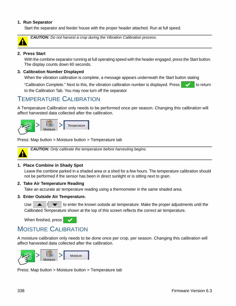
1. Run SeparatorStart the separator and feeder house with the proper header attached. Run at full speed.
CAUTION: Do not harvest a crop during the Vibration Calibration process.
2. Press Start With the combine separator running at full operating speed with the header engaged, press the Start button. The display counts down 60 seconds.
3. Calibration Number Displayed When the vibration calibration is complete, a message appears underneath the Start button stating
“Calibration Complete.” Next to this, the vibration calibration number is displayed. Press to return
to the Calibration Tab. You may now turn off the separator
TEMPERATURE CALIBRATION
A Temperature Calibration only needs to be performed once per season. Changing this calibration will affect harvested data collected after the calibration.
Press: Map button > Moisture button > Temperature tab
CAUTION: Only calibrate the temperature before harvesting begins.
1. Place Combine in Shady SpotLeave the combine parked in a shaded area or a shed for a few hours. The temperature calibration should not be performed if the sensor has been in direct sunlight or is sitting next to grain.
2. Take Air Temperature ReadingTake an accurate air temperature reading using a thermometer in the same shaded area.
3. Enter Outside Air Temperature.
Use / to enter the known outside air temperature. Make the proper adjustments until the Calibrated Temperature shown at the top of this screen reflects the correct air temperature.
When finished, press .
MOISTURE CALIBRATION
A moisture calibration only needs to be done once per crop, per season. Changing this calibration will affect harvested data collected after the calibration.
Press: Map button > Moisture button > Temperature tab
MoistureTemperature
MoistureMoisture
338 Firmware Version 6.3
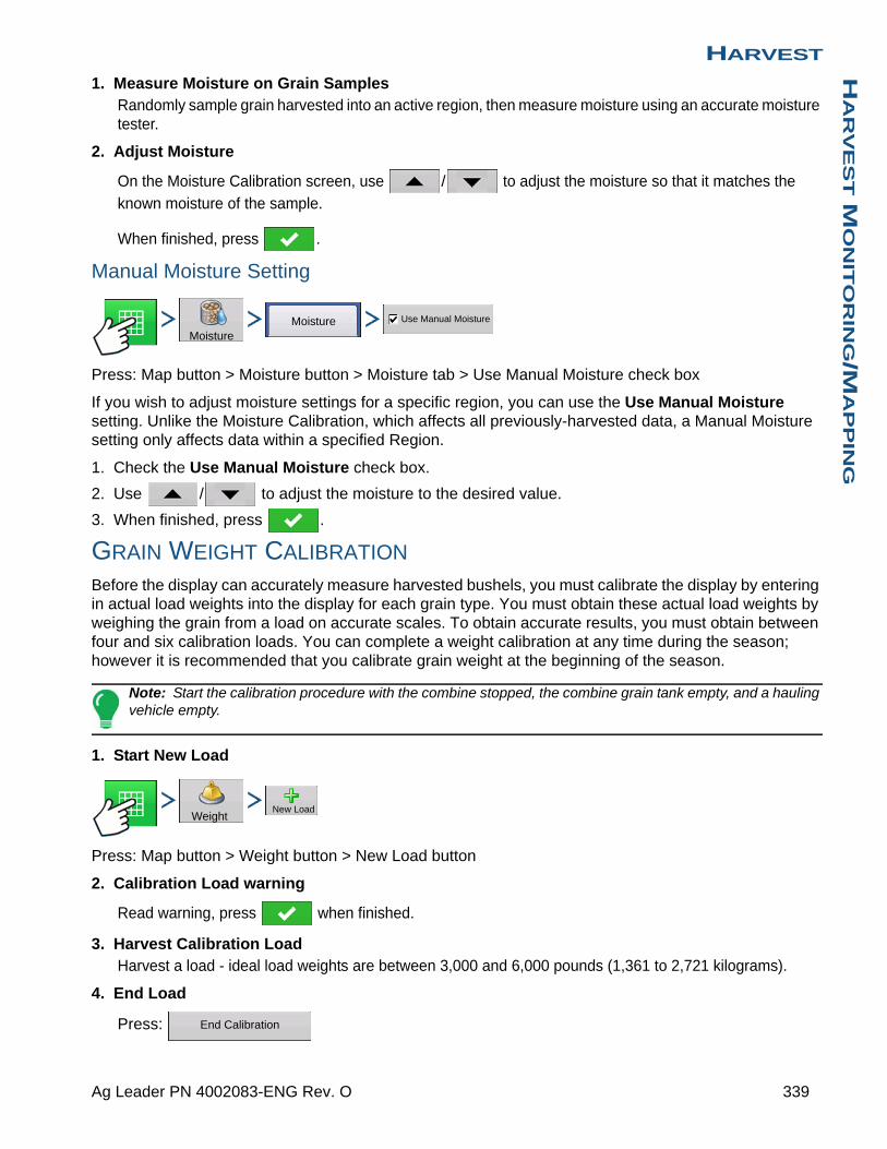
HARVESTH
AR
VE
ST M
ON
ITO
RIN
G/M
AP
PIN
G
1. Measure Moisture on Grain SamplesRandomly sample grain harvested into an active region, then measure moisture using an accurate moisture tester.
2. Adjust Moisture
On the Moisture Calibration screen, use / to adjust the moisture so that it matches the
known moisture of the sample.
When finished, press .
Manual Moisture Setting
Press: Map button > Moisture button > Moisture tab > Use Manual Moisture check box
If you wish to adjust moisture settings for a specific region, you can use the Use Manual Moisture setting. Unlike the Moisture Calibration, which affects all previously-harvested data, a Manual Moisture setting only affects data within a specified Region.
1. Check the Use Manual Moisture check box.
2. Use / to adjust the moisture to the desired value.
3. When finished, press .
GRAIN WEIGHT CALIBRATION
Before the display can accurately measure harvested bushels, you must calibrate the display by entering in actual load weights into the display for each grain type. You must obtain these actual load weights by weighing the grain from a load on accurate scales. To obtain accurate results, you must obtain between four and six calibration loads. You can complete a weight calibration at any time during the season; however it is recommended that you calibrate grain weight at the beginning of the season.
Note: Start the calibration procedure with the combine stopped, the combine grain tank empty, and a hauling vehicle empty.
1. Start New Load
Press: Map button > Weight button > New Load button
2. Calibration Load warning
Read warning, press when finished.
3. Harvest Calibration LoadHarvest a load - ideal load weights are between 3,000 and 6,000 pounds (1,361 to 2,721 kilograms).
4. End Load
Press:
MoistureMoisture Use Manual Moisture
WeightNew Load
End Calibration
339 Ag Leader PN 4002083-ENG Rev. O

5. Calibration Load warning
Read warning, press when finished.
6. Name Load
Display will give load a default name of time and date. Use to change the load name.
7. Empty Grain and Weigh LoadEmpty the grain tank completely onto a truck or wagon, and weigh it with an accurate scale. Record each individual load weight to be entered into the display. (No grain from any other combine should be unloaded into this hauling vehicle).
8. Weigh and Record Load Weight
Weigh the grain on the hauling vehicle and record the actual load weight by pressing on the Weight Calibration screen.
• If you are using a weigh wagon to weigh the grain, make sure the wagon has been calibrated properly.
• Only use one scale during this calibration process.
• Use the same vehicle for all calibration loads.
• Do not use a semi truck, as this vehicle’s capacity is too large for a calibration load.
9. Uncheck Loads With Excessive Error Percentages At the Grain Calibration screen, take note of any calibration loads that have excessive error percentages. In the example at left, a load has an error percentage of 11.7 percent.
You should be able to calibrate the display for grain weight to an average error of 1% to 3%. If the average error is more than 3%, uncheck the load with the maximum error.
Any load that is checked is automatically included in the calibration.
TURN ON/OFF AUTO CALIBRATION
Press: Map button > Weight button > Setup (wrench) button > AutoCal Weight check box
The display defaults to AutoCal Weigh checked. AutoCal Weight can be turned off by unchecking the check box.
Calibration 3, 12/12/2011
09:38 12/14/2011
09:42 12/14/2011
530
542
600
525
Load Name Weight Actual
Calibration Loads
Error
-11.7%
3.2%
Field Name
Ashton
Ashton
Time
09:36 1
09:39 1
New Load
Actual
Load Name
Weight Calibration
Average Load Error: 7.4 %
Weight
AutoCal Weight
340 Firmware Version 6.3

HARVESTH
AR
VE
ST M
ON
ITO
RIN
G/M
AP
PIN
G
AUTOSWATH SENSITIVITY SETTINGS
AutoSwath adjusts the swath width when crossing field boundaries and already-harvested areas. The display changes the swath width being harvested, even though no mechanical change takes place. AutoSwath is useful when harvesting point rows or where harvesting a full head width is not possible.
When performing a Harvest operation, the AutoSwath feature includes sensitivity levels, which compensate for varying levels of GPS accuracy.
Press: Home button > Setup (wrench) button > Configuration (tractor) button > Configuration tab > your specific configuration > Setup (wrench) button >Automatic Swath Control button
The Automatic Swath Control screen appears.
If swath adjustments are performing inaccurately, adjust the sensitivity accordingly. Sensitivity 3 is the default setting. Other settings include:
• Sensitivity 5Use with RTK or DGPS sub-meter, terrain compensated GPS.
• Sensitivity 4Use with RTK or DGPS sub-meter GPS. Terrain compensation recommended.
• Sensitivity 3Use with sub-meter accurate GPS.
• Sensitivity 2Use with 1+ meter accurate GPS.
• Sensitivity 1Swath sections are all on or all off. Use with 1+ meter accurate GPS.
LOAD CONFIGURATION
Press: Select Event button.
Select a Season, Grower, Farm, and Field on the Management Selection
screen.
For more information, see “Setup Event” on page 45.
RUN CONFIGURATION
Once a configuration has been completed, the Map View button appears at the bottom of the Home screen. Press the Map View button to see the Map screen.
ConfigurationSelect Your Specific
Configuration
Automatic Swath Control
Select Event
341 Ag Leader PN 4002083-ENG Rev. O

• (A) GPS Status
• (B) Total Field Area
• (C) Ground Speed
• (D) Diagnostics button
• (E) Map Legend (varieties)
• (F) Legend Select
• (G) Crop
• (H) Status Items
• (I) Home button
• (J) Map View button
• (K) Swath Width
• (L) AutoSwath
• (M) Logging Status button
• (N) Header Height %
• (O) Swath Width
• (P) Bushels Per Hour
• (Q) Elevator Speed
Note: Pressing the Map View button will cycle between the available Map screen views, and the appearance of the Map View button changes.
HARVEST STATUS ITEMS
• YieldDisplays the instantaneous yield while there is grain flow and the average yield when grain flow is not present.
• MoistureDisplays the instantaneous moisture when there is grain flow and the average when there is no grain flow.
• AreaShows the area harvested for the current region.
• Wet Weight Shows the actual weight that has been harvested for the region.
• Wet Bushels Shows the actual bushels that have been harvested for the current region.
• Dry Bushels Displays the actual number of bushels at the specified dry moisture percentage.
- If the actual moisture is below the set dry moisture percentage and “Expand Bushels for All Grains Below Dry %" is not checked, it will show actual bushels.
1979 lb
1.70 ac
160 bu/ac
5.0 mph1.7 ac
Yield
235 +215 - 235195 - 215175 - 1950 - 175
Grain Calibration
Weight Moisture
Rows: 12
Full Swath
Corn
C1545
Yield (Avg)
Moisture (Avg)
15.1 %Area
Wet Weight
Dry Bushels
35
Corn
0 bu/ hr
0 0 rpm
Yield
145.6 bu/ac
Moisture
16.5 %Area
12.28 ac
Wet Weight
274089 lbWet Bushels
4894 bu
Corn
342 Firmware Version 6.3
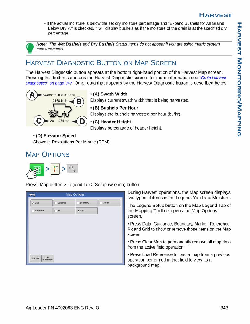
HARVESTH
AR
VE
ST M
ON
ITO
RIN
G/M
AP
PIN
G
- If the actual moisture is below the set dry moisture percentage and "Expand Bushels for All Grains Below Dry %" is checked, it will display bushels as if the moisture of the grain is at the specified dry percentage.
Note: The Wet Bushels and Dry Bushels Status Items do not appear if you are using metric system measurements.
HARVEST DIAGNOSTIC BUTTON ON MAP SCREEN
The Harvest Diagnostic button appears at the bottom right-hand portion of the Harvest Map screen. Pressing this button summons the Harvest Diagnostic screen; for more information see “Grain Harvest Diagnostics” on page 347. Other data that appears by the Harvest Diagnostic button is described below.
• (A) Swath WidthDisplays current swath width that is being harvested.
• (B) Bushels Per HourDisplays the bushels harvested per hour (bu/hr).
• (C) Header HeightDisplays percentage of header height.
• (D) Elevator SpeedShown in Revolutions Per Minute (RPM).
MAP OPTIONS
Press: Map button > Legend tab > Setup (wrench) button
During Harvest operations, the Map screen displays two types of items in the Legend: Yield and Moisture.
The Legend Setup button on the Map Legend Tab of the Mapping Toolbox opens the Map Options screen.
• Press Data, Guidance, Boundary, Marker, Reference, Rx and Grid to show or remove those items on the Map screen.
• Press Clear Map to permanently remove all map data from the active field operation
• Press Load Reference to load a map from a previous operation performed in that field to view as a background map.
2160 bu/h
Swath: 30 ft 0 in 100%
20 474 rpm
Data
Reference
Guidance
Rx
Boundary
Grid
Marker
Clear MapLoad
Reference
Map Options
343 Ag Leader PN 4002083-ENG Rev. O

MAP SCREEN: FLOW DELAY
When the Map screen is running in a Zoom Detail view, instantaneous coverage (A) is shown automatically. However, there is a time lag between when grain enters the combine through the Header and is logged by the Flow Sensor in the Clean Grain Elevator. Because of this time lag, the instantaneous coverage is shown on the Map screen as a lighter color than coverage that has been logged (B) by the display.
REGION SELECTION: OPTIONS SCREEN
Press: Home button > Region button
The Region button, located on the Home screen, opens the Options screen where you can change or edit regions, select Automatic Variety Tracking or Automatic Region Changing.
Note: The Options screen also appears when you create a Field Configuration with the Field Operation Wizard.
• For more information about Automatic Variety Tracking or Automatic Region Changing, see “Tracking Varieties and Changing Regions” on page 344.
TRACKING VARIETIES AND CHANGING REGIONS
You can use the Options screen to enable the display to track varieties that you planted earlier and are now harvesting. You can also use two types of variety tracking: Automatic Variety Tracking and Automatic Region Changing.
• Automatic Variety Tracking tracks only varieties; hence the operator must manually change to a new region.
Note: You can select the Variety Tracking option when you are creating a crop during Harvest Product Setup.
• Automatic Region Changing tracks both varieties and regions, so the display changes the region automatically.
Region:
<1>
Options
Automatic Variety Tracking
Automatic Region Changing
Import Variety Map
--NONE--
Variety Tracking
<1>
344 Firmware Version 6.3

HARVESTH
AR
VE
ST M
ON
ITO
RIN
G/M
AP
PIN
G
The illustration at left shows how the display could track two different varieties.
In this example, when the harvester reaches the end of Variety 1, and the operator maneuvers the vehicle to Variety 2, a message appears that either a new variety has been detected and the operator is notified to change regions (Automatic Variety Tracking,) or that a variety has been detected and the display is automatically changing regions. (Automatic Region Changing).
Variety Tracking menu and Automatic Variety Tracking
• Press to enter your own name for a new region.
Automatic Variety Tracking
• If you want to enable the Automatic Variety Tracking feature, select only the Automatic Variety Tracking check box. (Do not select the Automatic Region Changing check box).
Note: A variety map must be present to enable Automatic Variety Tracking.
• If no variety map is present, then you can either- manually assign a variety from the Variety Tracking List, located to the right of the Automatic Variety
Tracking check box; or
- import a variety reference map. For more information, see “Importing Variety Maps” on page 346.
Automatic Region Changing
If you wish to enable the Automatic Region Changing feature, select both the Automatic Variety Tracking check box, and the Automatic Region Changing check box.
In-Field Messages
If you have selected either the Automatic Variety Tracking or Automatic Region Changing features, you will see one of the following messages as you harvest your field.
• If you have selected Automatic Variety Tracking, a message will tell you that the display has detected a different variety, and that you should manually change the region.
Options
Automatic Variety Tracking
Automatic Region Changing
Clear Variety Map
--NONE--
Variety Tracking
<1>
345 Ag Leader PN 4002083-ENG Rev. O
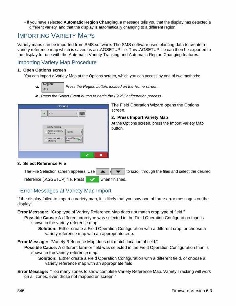
• If you have selected Automatic Region Changing, a message tells you that the display has detected a different variety, and that the display is automatically changing to a different region.
IMPORTING VARIETY MAPS
Variety maps can be imported from SMS software. The SMS software uses planting data to create a variety reference map which is saved as an .AGSETUP file. This .AGSETUP file can then be exported to the display for use with the Automatic Variety Tracking and Automatic Region Changing features.
Importing Variety Map Procedure1. Open Options screen
You can import a Variety Map at the Options screen, which you can access by one of two methods:
-a. Press the Region button, located on the Home screen.
-b. Press the Select Event button to begin the Field Configuration process.
The Field Operation Wizard opens the Options screen.
2. Press Import Variety MapAt the Options screen, press the Import Variety Map button.
3. Select Reference File
The File Selection screen appears. Use / to scroll through the files and select the desired
reference (.AGSETUP) file. Press when finished.
Error Messages at Variety Map Import
If the display failed to import a variety map, it is likely that you saw one of three error messages on the display:
Error Message: “Crop type of Variety Reference Map does not match crop type of field.”Possible Cause: A different crop type was selected in the Field Operation Configuration than is
shown in the variety reference map.Solution: Either create a Field Operation Configuration with a different crop; or choose a
variety reference map with an appropriate crop.
Error Message: “Variety Reference Map does not match location of field.”Possible Cause: A different farm or field was selected in the Field Operation Configuration than is
shown in the variety reference map.Solution: Either create a Field Operation Configuration with a different field, or choose a
variety reference map with an appropriate field.
Error Message: “Too many zones to show complete Variety Reference Map. Variety Tracking will work on all zones, even those not mapped on screen.”
Region:
<1>
Options
Automatic Variety Tracking
Automatic Region Changing
Import Variety Map
--NONE--
Variety Tracking
<1>
346 Firmware Version 6.3

HARVESTH
AR
VE
ST M
ON
ITO
RIN
G/M
AP
PIN
G
Possible Cause: The reference file selected exceeded the allowable memory limit used to load reference maps.
Solution: Continue harvest operations. All variety tracking and region information will be logged. However you will not be able to see the entire reference map on the display’s map screen.
GRAIN HARVEST DIAGNOSTICSWhen performing a Harvest operation, you can also access the Harvest Diagnostic screen by pressing the Display Information button. Technical support may request that you look at this screen for help in diagnosing a problem. When the Devices screen opens, press and
highlight the Moisture Module listing in the CAN Device list, then press the Diagnostics button. The Grain Harvest Diagnostics screen appears.
The Grain Harvest Diagnostics screen includes the following information:
• Flow RateGrain flow rate, shown in kilograms per second.
• Flow Max, Flow Min and Flow OffsetRaw flow values used for diagnostic purposes.
• Sensor ForceForce of grain flow, shown in Newtons.
• Header RawRaw value of header sensor.
• Speed PulsesShows the number of ground speed pulses from the combine.
• Moisture RawRaw value of moisture sensor.
• TemperatureAir temperature, shown in Celsius.
• Temperature RawRaw value of temperature sensor.
• Proximity SensorShows if Elevator Mount Unit sensor is covered with grain.
• Relay StatusShows on or off.
• Motor CurrentMeasure of Elevator Mount Unit (EMU) current, shown in amps.
Grain Harvest Diagnostics
Region Distance 18257 ft
Flow Rate 5.12Flow Max 216Flow Mn 172Flow Offset 350Sensor Force 9.95Header Raw 296Speed Pulse 103
Moisture Raw 3.21Temperature -3.8Temperature Raw 2.69Proximity Status ONRelay Status ONMotor Current 0.9
347 Ag Leader PN 4002083-ENG Rev. O

348 Firmware Version 6.3

HARVESTC
LA
AS Q
UA
NT
IME
TE
R
HARVEST
CLAAS QUANTIMETERThe CLAAS Quantimeter Optical Sensing System includes the option of interfacing with the display. This option is available for LEXION combines of the 670 model and above. The display communicates with a Bridge Module. This Bridge Module receives data from the combine via the CEBIS (CLAAS Electronic On-Board Information System) monitor which is then relayed to the display. The Bridge module can also interface with the ParaDyme Automated Steering system.
CREATE CONFIGURATION
Press: Home button > Setup (wrench) button > Configuration (tractor) button > Configuration tab > Add (+) button > Harvest button
1. Use drop-down menu to select make and model of Lexion.
2. Press to enter offsets. Press to continue.
3. Select Header from the drop-down menu or press to add a header. Press to continue.
4. Select Speed Sources and Calibrate Speed Sensor. Press to continue.
5. Enter Configuration Name
A suggested name for the configuration appears. If desired, press to enter a different name for
your configuration. Press when complete.
CONFIGURATION SETUP
Press: Home button > Setup (wrench) button > Configuration (tractor) button > Configuration tab > your specific configuration > Setup (wrench) button
The Configuration Setup screen appears. Screen’s appearance differs if using a CLAAS Quantimeter configuration.
Configuration Harvest
ConfigurationYour Specific Configuration
Lexion 670, 30 ft Platform
Implement: 30 ft Platform
Vehicle
Lexion 6701
Full Swath:
Rows:
30.000 feet
N/A
Controller: Lexion 670
Map Delays
GPS Offset
Grain Calibration
Equipment Settings
Speed Input
Automatic Swath Control
Header Offset
Configuration Setup
349 Ag Leader PN 4002083-ENG Rev. O

Note: Adjustment of Combine Settings and the Header Sensor Calibration is performed through the CLAAS CEBIS monitor.
• Vehicle OffsetsFor more information, see “Vehicle Offsets” on page 85.
• Speed InputThe ground speed source can be changed by pressing the Speed Input button. This opens the Speed Input screen, where you can choose a primary speed source of GPS, Wheels or Radar. For more information, see “Speed Input Settings” on page 80.
Note: If you are using a CLAAS Quantimeter, you do not choose a secondary speed source.
• Grain CalibrationFor more information, see “Calibration Information” on page 350.
• Automatic Swath ControlFor more information on AutoSwath, see “AutoSwath Sensitivity Settings” on page 341.
• Header OffsetFor more information, see “Input Header Offset” on page 337.
• Map DelaysPress to change the Map Delay settings.
CAUTION: Do not change settings from the default value of 4 without specific instruction from Technical Support!
CALIBRATION INFORMATION
Most calibration information used in a CLAAS Quantimeter configuration is calculated in the CEBIS monitor and then relayed to the display. For CLAAS Quantimeter configurations, the CEBIS monitor performs calibrations for the Header Sensor, Yield Monitor, Moisture and Temperature.
Note: The calibration created in the CLAAS Quantimeter is a linear calibration.
When a new calibration is started in the CEBIS monitor, a warning appears on the display, stating “A new grain calibration has been detected. Select an operating configuration to continue.” At the same time, the display unloads the Field Operating Configuration that was collecting data with the old
calibration. Acknowledge the New Grain Calibration warning by pressing .
LOAD CONFIGURATION
Press: Select Event button.
Select a Season, Grower, Farm, and Field on the Management Selection
screen.
For more information, see “Setup Event” on page 45.
Select Event
350 Firmware Version 6.3

HARVESTC
LA
AS Q
UA
NT
IME
TE
R
Create a new Field Operation Configuration.
After you have completed the grain weight calibration and a new calibration factor has been calculated in the CEBIS monitor, this new calibration is then sent to the display. The display then uses the new calibration to update all data collected since the time it detected the start of the new calibration. No further messages appear in the display.
Note: The New Grain Calibration warning does not appear for the first calibration performed during the season. It only appears for calibrations performed thereafter.
Note: The display does not update any previously-collected data collected prior to the time it detected the start of the new calibration.
Manual Moisture Setting
As with other calibration information, the Moisture Calibration is calculated in the CEBIS monitor and then relayed to the display. However, you can adjust moisture settings for a specific region with the displays Manual Moisture setting. The manual moisture setting will only be applied to the specified region.
Press: Home button > Setup (wrench) button > Configuration (tractor) button > Configuration tab > your specific configuration > Setup (wrench) button > Grain Calibration button
The CLAAS Calibration screen appears.
1. Check .
2. Use / to adjust the Manual
Moisture to the desired value. Press when finished.
Note: The list shown in the CLAAS Calibration screen only shows loads harvested during the current season.
ConfigurationYour Specific Configuration
Grain Calibration
Lexion Calibration
Moisture Calibrations
15.0 %
Use Manual Moisture
Use Manual Moisture
351 Ag Leader PN 4002083-ENG Rev. O

MAP SCREEN FOR CLAAS QUANTIMETER
Once an operating configuration is created for a CLAAS Quantimeter harvest configuration, and a field operation configuration is created at the Home screen, you can view map screen data.
For the most part, this map screen is similar in appearance to the map screen used in other Harvest configurations. However, the Harvest Diagnostic button, shown at the bottom right-hand side of the Equipment Tab (A), differs in appearance from that shown on other Harvest configuration map screens. This Harvest Diagnostic button does not display a picture of a combine.
The top of the Harvest Diagnostic button displays the following information:
• For configurations using a Platform Head or Pickup Head - Swath Width, shown both in units of measurement and as a percentage total.
• For configurations using a Row Head - Number of active rows.
The Harvest Diagnostic button also displays this information for all CLAAS configurations:
• Grain Flow
• Header Height - shown as a percentage
• Engine Speed - shown in revolutions per minute
• Fuel - fuel consumption of the combine
Note: Elevator Speed information is not shown for CLAAS Quantimeter configurations.
DIAGNOSTICS FOR CLAAS QUANTIMETER
Diagnostics Screen for CLAAS Quantimeter
When performing a Harvest operation, you can access the Grain Harvest Diagnostics screen by pressing the Display Information button. Technical support may request that you look at this screen for help in diagnosing a problem. When the Devices screen opens, press
and highlight the AL Bridge listing in the CAN Device list, then press the Diagnostics button. The Grain Harvest Diagnostics screen appears.
136 +116 - 13696 - 11676 - 960 - 76
Yield
Soybeans
1.06 ac 5.0 mph
Yield
Moisture
Area
Wet Weight
Dry Bushels
Soybeans
118.6
15.9
1.06
6797
111
Swath: 30 ft 0 in 100%
Flow
Header
Engine Speed
Fuel
2205 bu/h
25%
1115 rpm
3 gal/h
Full SwathMoisture
bu/ac
%
ac
lb
bu
352 Firmware Version 6.3
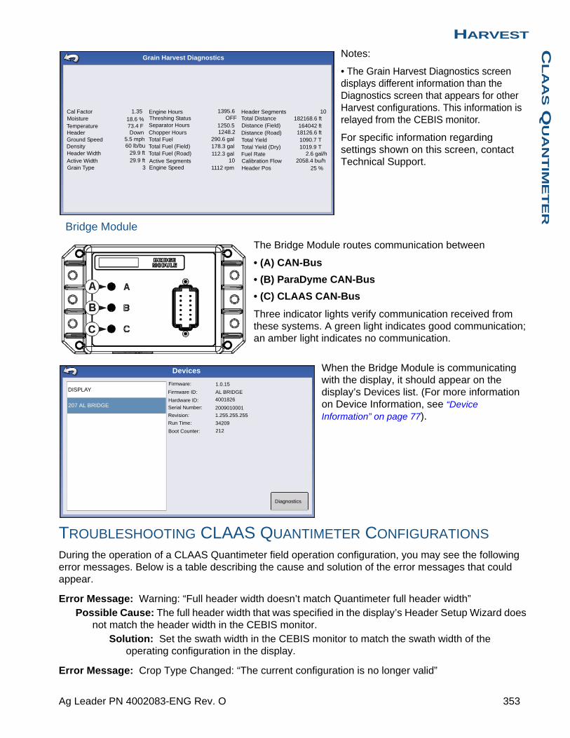
HARVESTC
LA
AS Q
UA
NT
IME
TE
R
Notes:
• The Grain Harvest Diagnostics screen displays different information than the Diagnostics screen that appears for other Harvest configurations. This information is relayed from the CEBIS monitor.
For specific information regarding settings shown on this screen, contact Technical Support.
Bridge Module
The Bridge Module routes communication between
• (A) CAN-Bus
• (B) ParaDyme CAN-Bus
• (C) CLAAS CAN-Bus
Three indicator lights verify communication received from these systems. A green light indicates good communication; an amber light indicates no communication.
When the Bridge Module is communicating with the display, it should appear on the display’s Devices list. (For more information on Device Information, see “Device Information” on page 77).
TROUBLESHOOTING CLAAS QUANTIMETER CONFIGURATIONS
During the operation of a CLAAS Quantimeter field operation configuration, you may see the following error messages. Below is a table describing the cause and solution of the error messages that could appear.
Error Message: Warning: “Full header width doesn’t match Quantimeter full header width”Possible Cause: The full header width that was specified in the display’s Header Setup Wizard does
not match the header width in the CEBIS monitor.Solution: Set the swath width in the CEBIS monitor to match the swath width of the
operating configuration in the display.
Error Message: Crop Type Changed: “The current configuration is no longer valid”
Cal FactorMoistureTemperatureHeaderGround SpeedDensityHeader WidthActive WidthGrain Type
1.3518.6 %73.4 FDown
5.5 mph60 lb/bu
29.9 ft29.9 ft
3
Engine HoursThreshing StatusSeparator HoursChopper HoursTotal FuelTotal Fuel (Field)Total Fuel (Road)Active SegmentsEngine Speed
1395.6OFF
1250.51248.2
290.6 gal178.3 gal112.3 gal
101112 rpm
Header SegmentsTotal DistanceDistance (Field)Distance (Road)Total YieldTotal Yield (Dry)Fuel RateCalibration FlowHeader Pos
10182168.6 ft
164042 ft18126.6 ft1090.7 T1019.9 T
2.6 gal/h2058.4 bu/h
25 %
Grain Harvest Diagnostics
Firmware:
Firmware ID:
Hardware ID:
Serial Number:
Revision:
Run Time:
Boot Counter:
1.0.15
AL BRIDGE
4001826
2009010001
1.255.255.255
34209
212
Devices
DISPLAY
207 AL BRIDGE
Diagnostics
353 Ag Leader PN 4002083-ENG Rev. O

Possible Cause: The display has detected that the crop type specified in the CEBIS monitor has changed to a crop type that is different than what is specified in the display’s field operation configuration.
Either:
Solution: 1. Change the crop type specified in the CEBIS monitor back to what is specified in the display. Then reload the display’s field operation configuration.
Or
Solution: 2. Create a new field operation configuration that includes the new crop type. If necessary, create a new Harvest Product in Product Setup with the Harvest Crop Wizard. For more information, see “Grain Harvest Settings” on page 23.
Error Message: Grain Calibration: “A new grain calibration has been detected. Select an operating configuration to continue.” Possible Cause: When a new calibration is started in the CEBIS monitor, the warning at left
appears on the display. At the same time, the display unloads the Field Operating Configuration that was collecting data with the old calibration.
Solution: Acknowledge the warning by pressing . At the Home screen, press the Select Event button. Use the Field Operation Wizard to create a new field operation configuration. After receiving the new calibration from the CEBIS monitor, the display will calculate that field operation configuration’s harvest data by using this new calibration that was sent from CEBIS. (Also discussed in “Calibration Information” on page 350).
Error Message: CLAAS Communication Error: “Cannot communicate with CLAAS bridge module.”Possible Cause: No communication between Bridge Module and CLAAS CAN-Bus. (Shown as
Indicator Light C on Bridge Module in “Bridge Module” on page 353).Solution: Check cabling between Module and CLAAS Can-Bus.
Error Message: CAN Node Lost: “AL Bridge Node has stopped communicating.”Possible Cause: No communication between Bridge Module and display. (Shown as Indicator Light
A on Bridge Module in “Bridge Module” on page 353).Solution: Check cabling between Bridge Module and display.
354 Firmware Version 6.3

A
PP
EN
DIX
APPENDIX
APPENDIX
SYSTEM DIAGRAMS REFERENCETo view detailed system diagrams for various machine configurations, go to the Support tab of the Ag Leader Web site, which can be referenced via the following URL:
http://www.agleader.com/customer-support/product-manuals/
Note: To view and/or print the System diagrams, you will need the Adobe Acrobat or Adobe Reader .pdf file format. The Adobe Reader software comes pre-installed on most personal computers. If Adobe Reader is not installed on your computer the program is available for download at no charge. A link to the Adobe download
site is located at the Ag Leader Web site.
CURRENT FILE FORMATS
.AGSETUPUse to transfer setup information from display to display or from SMS and display
• Replaces MSF, IBY, PAT, IRX, REF
• Allows full synchronization of the following items:
• Management Data (Growers, Farms, Fields, Seasons, Operators)
• Products and Product Mixes
• Boundaries
• Guidance Patterns
• Marker Sets and Markers
Note: Do not use the IBK to “clone” a display anymore. Use AGSETUP.
.AGDATA• Includes all the necessary data to fully archive in SMS
• Includes recorded operation data
• Equipment Used
• Products Used
• Marks Logged
• Boundaries
• Guidance Patterns
• Flexible export options
• Will be able to export by Grower
355 Ag Leader PN 4002083-ENG Rev. O

LEGACY FILE FORMATS
PRESCRIPTION MAP FILE TYPES
• .irxThe .irx file supports multiple product recommendations in a single file.
• .shp, .shx, .dbf (shape file group)What is commonly called a shape file is actually a collection of three different files. All three of the files are required and must be present on the USB drive for the system to use shape file groups for variable rate product application. A single "shape file" can contain recommendation rates for multiple products.
Note: Legacy Prescription file (.irx) is supported and enhanced. Shape file (.shp, .shx, .dbf) continues to be supported for prescription control.
BOUNDARY AND GUIDELINE FILE TYPES
• .ibyBoundary file format. Boundary files are created at the Boundary tab, found on the Mapping Toolbox of the Map screen; or imported to the system from the Import Files button at the External Storage Operations screen. The External Storage Operations screen can be accessed by pressing the External Storage Operations button on the Home screen.
• .patPattern guideline file. Pattern files are created at the Guidance tab, found on the Mapping Toolbox of the Map screen; or imported to the system from the External Storage Operations button on the Home screen. The External Storage Operations screen can be accessed by pressing the External Storage Operations button on the Home screen.
Note: Legacy boundary file (.iby) and legacy pattern file (.pat) import and export will be supported for compatibility with Insight and Edge displays
IMAGE FILE TYPES
• .png and .bmpSupported file formats for the Display Owner Image. File size is limited to a maximum of 200 pixels wide by 100 pixels tall. Import the file from the Import Image button on the Display screen’s General tab.
SYSTEM FILE TYPES
• .ibkSystem backup file. Backup files are written to the USB drive by pressing the Create Backup button on the Display Setup screen’s Advanced tab.
• .ilf System log file. Created with the Copy Data button on the External Storage Operations screen or pressing the Export Data Files button of the Display screen’s Advanced tab.
• .fw2Firmware upgrade file for the display and control modules. Install firmware updates from the USB drive by pressing the Upgrade Firmware button on the External Storage Operations screen. The External Storage Operations screen can be accessed by pressing the External Storage Operations button on the Home screen.
356 Firmware Version 6.3

A
PP
EN
DIX
• .msfThe .msf (Management Setup File) file format allows the display to import Grower and Field information from SMS software via the USB drive.
• .refVariety reference map file. SMS software uses planting data to create a variety reference map which is saved as a .ref file. This .ref file can then be exported to the display for use with the Automatic Variety Tracking and Automatic Region Changing features.
Note: Legacy Reference files (.ref) will not be supported in 3.0. SMS will be able to include variety maps in .AGSETUP for harvest variety tracking.
Note: IBK, MSF are not supported in 3.0. Use the new .IBK2 format for backups in 3.0. IBK2 will continue to be specific to a particular display model. Version 3.0 will not restore from an “IBK” from previous releases.
MODULE LED DIAGNOSTIC STATES• OffNo power
• Flashing 1 Hz greenNormal operation
• Flashing 1 Hz orangeCAN bus errors detected (error active/passive state)
• Steady orangeCAN bus off
• Steady redHardware or initialization failure
• Flashing 1 Hz redFirmware download in progress
• Flashing fast redFirmware download error
COMPANY WARRANTY STATEMENTAg Leader Technology will repair or replace at no charge any component of the display that fails during normal service, while being used in an approved application, within two years of the warranty start date. Warranty is not provided for damage resulting from abuse, neglect, accidents, vandalism, acts of nature, or any causes that are outside of the normal intended use of the display. Ag Leader Technology shall not be liable for indirect, incidental, or consequential damages to the dealer, end user, or third parties arising
from the sale, installation, or use of any Ag Leader Technology product.
UNAUTHORIZED ACCESSCertain features of the display can be locked-down by authorized personnel having password access and should be changed only by authorized personnel having password access. Unauthorized access to the locked-down features is prohibited. Attempts to access the locked-down features by unauthorized
357 Ag Leader PN 4002083-ENG Rev. O
personnel constitutes fraud. Ag Leader is not responsible for any damage or loss incurred as a result of access to the locked-down features by unauthorized personnel and you as owner of the display agree to indemnify and hold harmless Ag Leader, its, partners, subsidiaries, agents, affiliates, and/or licensor(ee)s, as applicable, for any unauthorized access to the locked-down features.
PROPRIETARY TECHNOLOGY NOTICEAg Leader Technology's display has patents on its design and operational features. Copying features of this system relating to measurement and calculation of grain flow and weight, organization of field and load data may result in patent infringement.
COPYRIGHT NOTICEAg Leader Technology has copyrighted (© 2013) the contents of this manual and the operating program for the display. No reproductions may be made without first obtaining the consent of Ag Leader Technology.
SERVICE AND SUPPORTYour display was designed with simplicity and ease of use in mind. This manual has been provided to help familiarize yourself with the display and its basic functionality. Setup wizards are implemented where appropriate within the system to further simplify configuration and use.
If you have additional questions or feel that you may be having a problem with your system, call your local Ag Leader Technology dealer or call us directly at the phone number below. If we determine you have a hardware failure, we will ship replacement hardware immediately.
Our Technical Support Department can be reached by phone at 515-232-5363 extension #1 or through email at [email protected].
358 Firmware Version 6.3

IN
DE
X
IndexAAB/smartpath toggle 133active line cycle 134adaptive curve 128
area count 135heading change 135heading threshold 135new pass 135
adaptive pattern options 135Add a User 34add configuration 21add product 22add product mix 22all area covered 135area 342area count 135automatic region changing 344, 345, 346automatic swath control 341automatic variety tracking 344, 345autoswath 341
RTK 341sensitivity 341
Bbase path 134Basic Permission 36boundary 343bushels per hour 343
Ccalibrate header sensor 336calibration load 339calibration sequence 335CAN device list
moisture module 347cancel 127, 128, 130, 131center pivot 130clean grain elevator 335, 344clear map 343clear nudge 140configuration settings 335configuration tab
add button 21console button 16copy all files 335
crop settingsexpand bushels 23
crop settings screen 23Custom Permission 37
Ddata 343delete product 22diagnostic 343diagnostics 347
flow max 347flow min 347flow offset 347flow rate 347header raw 347moisture raw 347motor current 347proximity sensor 347relay status 347sensor force 347speed pulses 347temperature 347temperature raw 347
diagnostics button 347, 352dry bushels 342
EEdgeVac 211
sensors 211edit info button 23edit legend button 23edit pattern 136edit product 22elevator mount unit sensor 347elevator speed 343EMU sensor 347expand bushels 23export pattern 136
Ffield 31flow delay 344flow max 347flow min 347flow offset 347flow rate 347flow sensor 344followed path 134Full Permission 36
359 Ag Leader PN 4002083-ENG Rev. O

Ggear ratio
example 179, 181multiple drives 179, 180single motor drive 178
gear ratio calculation 178GPS button 16grain harvest diagnostics 347grain settings screen 23grain weight calibration 339grid 343Grower 30grower 30guidance 343guidance options
adaptive curve 135guidance tab 126
cancel 127, 128, 130, 131pause 127, 128, 130, 131resume 127, 128, 130, 131
Hharvest diagnostic button 343harvest diagnostic screen 343header height 343header offset 337header raw 347header sensor
reset all 337heading change 135heading threshold 135home screen 15
Iidentical curve 129import product 22import variety map
reference file 346import variety maps 346
error messages 346instantaneous coverage 344
Llegend
moisture 343yield 343
legend referencegrid 343Rx 343
legend select 343boundary 343clear map 343data 343guidance 343load reference 343marker 343reference 343
legend setup button 343load reference 343load weight 339logged area 135
Mmanage patterns
edit pattern 136export pattern 136
management setupfield 31grower 30season 33
Managers 35map screen
flow delay 344mapping toolbox 126marker 343metric 343moisture 342, 343moisture calibration 338moisture module 347moisture raw 347motor current 347
Nnew AB pattern 127new pass 135nudge 140
Ooperating configuration 21options screen 344
import variety map 346
Ppause 127, 128, 130, 131, 139Permission Level 36pivot 130
cancel 132number of rows 132row spacing 132
360 Firmware Version 6.3

IN
DE
X
shift by distance 132shift by rows 132
planter configurationEdgeVac 211
pre-harvest preparation 335product name 22product option 22
add product 22add product mix 22import product 22
product settings screen 23product setup 22product tab 22
add 22crop settings 23delete 22edit 22edit info 23edit legend 23grain settings 23
projected path 134proximity sensor 347
Rreference 343reference file 346region button 344
options screen 344relay status 347remark A 139remove all 137remove all patterns 137remove button 137remove pattern 137reset 137reset all 337reset button 134reset pattern 137resume 127, 128, 130, 131, 139rting 346Rx 343
Ssave button 134season 33sensor force 347setup buttons 16
console 16GPS 16
setup product 22setup screen 22
product settings 23shift by distanc 132shift by distance 141shift by rows 132, 141smart tab 135smartpath 132
active line cycle 134all area covered 135base path 134followed path 134heading threshold 135logged area 135notes 134projected path 134reset button 134save button 134select previous pass 134smart tab 135
speed pulses 347status items 342
area 342dry bushels 342metric 343moisture 342wet bushels 342wet weight 342yield 342
stepper seed controlgear ratio 178
Straight Track 127swath width 343
Ttemperature 347temperature calibration 338temperature raw 347
Vvariety map 345variety tracking 344, 345
messages 345vibration calibration 337
number 338
Wweight calibration 339wet bushels 342
361 Ag Leader PN 4002083-ENG Rev. O

wet weight 342
Yyield 342, 343
362 Firmware Version 6.3