operator manual - heartland medical · the amsco sq240 surgical lighting system has been designed...
TRANSCRIPT

OPERATOR MANUAL
Amsco® SQ240TM Surgical Lighting SystemsCentra Mount/Track Mount
Amsco® SQ240 SurgiVisionTM Surgical Lighting andVideo SystemCentra Mount
(05/29/01) P-150824-909Rev. 10

i150824-909
Advisory
A WORD FROM STERIS CORPORATION
© 2000, STERIS Corporation. All rights reserved. Printed in U.S.A.
This manual contains important information on proper use and care of thissurgical lighting fixture. All operators and department heads are urged tocarefully review and become familiar with the warnings, cautions, and instruc-tions contained herein. Your new surgical lighting fixture features an advanced,state-of-the-art design, with cool, shadow-reduced light, and ease of maneu-verability. It produces light of a quality necessary for the most demanding andcomplex of surgical procedures.
A thorough preventive maintenance program is essential to safe and properoperation of your surgical light. You are encouraged to contact STERIS concern-ing our Annual Maintenance Agreement. Under terms of this agreement,preventive maintenance, adjustments, and replacement of worn parts are doneon a scheduled basis to assure lighting fixture performance at peak capabilityand to help avoid untimely or costly downtime. STERIS maintains a nationwidestaff of well-equipped, factory-trained technicians to provide this service, as wellas expert repair services. Contact your STERIS representative for details.
The Amsco® SQ240 SurgiVisionTM Surgical Lighting and Video System fromSTERIS is a high-resolution video system integrated into the lighthead of anSQ240 light. This video system, designed into the camera housing thataccepts the sterilizable handle, enables the Customer to document surgicalprocedures for a variety of reasons, including teaching and archival purposes.
A remote hand-held wireless control allows the Customer to control the keyvideo functions of the system; zoom, image-field rotation, and focus of thecamera. An optional foot control accessory (not available on Hermes-readysystems) is available to activate the video system zoom and rotation functions.
The Hermes-ready system requires the use of a Hermes control center (notsupplied by STERIS) that allows the customer to control key video functions(zoom, image-field rotation and focus) using verbal commands or a hand-heldtouch screen pendant.
The Amsco® SQ240TM Surgical Lighting System provides cool, color-cor-rected, shadow-controlled illumination of the surgical field during surgicalprocedures in the operating theatre.
The following is an important message from STERIS about theadvantages and limitations associated with the use of highintensity surgical lighting systems.Because of the variety of surgical procedures performed and the wide rangeof individual preferences of surgical staffs, it is desirable that the surgicallighting system be capable of selective control across a wide range ofillumination intensities. The Illuminating Engineering Society (IES) stressesthat in addition to providing control of intensity, surgical lighting systemsshould provide shadow control, correct color rendition, and a suitable depthof field to provide sharp, consistent lighting into deep body cavities.
The IES states that the surgical lighting system should be capable of providinga minimum of 2,500 footcandles of light directed to the center of the pattern.Although the IES does not recommend a maximum illumination intensity, itcautions that as illumination intensities increase to maximum settings, radiantheat will also increase. The IES further cautions that for most operations, infraredradiant energy in the spectral region of 800 to 1000 nm should be kept to a
Indications for Use
1234567890123456789012345678901212345678901234567890123456789012
1234567890123456789012345678901212345678901234567890123456789012
1234567890123456789012345678901212345678901234567890123456789012
1234567890123456789012345678901212345678901234567890123456789012

ii150824-909
minimum. In certain neurosurgical or intestinal procedures on delicate, thin, dryor abnormal tissue, the user of surgical lights should take care to utilize thelowest possible illumination intensity suitable for the procedure.
The Amsco SQ240 Surgical Lighting System has been designed to providemaximum illumination flexibility and at the same time minimize potentiallydamaging infrared heat in the surgical field. Illumination intensity of the SQ240Surgical Light can be adjusted through five intensity settings on the VariableIntensity Controller (VIC). Typical illumination performance can be expected torange between approximately 6,000 footcandles at position number 1 on theVIC and 12,000 footcandles at position number 5. For the protection ofsurgically exposed tissues and for the comfort and efficiency of the surgeonand assistants, radiant energy can be effectively controlled by limiting the timeof exposure at the higher intensity settings on the VIC.
NOTE: This device is in compliance with IEC 60601-1-2 (1st Edition, 1993-04),Medical Electrical Equipment – Part 1: Gneral Requirements for Safety;Electromagnetic Compatibility (EMC). There is, however, apotential for electro-magnetic or other interference between this equipment and other devices.Should you experience interference, relocate the device or minimize the useof the affected equipment while this device is operating.
ManufacturedExclusively by
STERIS Corporation Montgomery, AL
ISO 9001EN 46001ISO 13485Certified
The base language of this document isENGLISH. Any translations must be
made from the base language document.
STERIS offices worldwide:Canada 800 661 3937Germany 49 2233 6999 400Hong Kong 852 2 563 3623Italy 39 0141 590429Japan 81 78 252 1901Korea 82 2 554 1661Latin America 305 442 8202Singapore 65 841 7677Spain 34 91 658 5920United Kingdom 44 1 608 811 822
EC Authorized Representative
STERIS Ltd.The Stable Block, Cornbury ParkCharlburyOxfordshire OX7 3EHENGLAND
Manufactured by:
STERIS Corporation2720 Gunter Park EastMontgomery, AL 36109 • USATEL: 334 277 6660FAX: 334 271 5450
Class 1 EquipmentType B EquipmentOrdinary Equipment (enclosed equipment without protection of ingress of water)Equipment not suitable for use in the presence of a flammable anesthetic mixture withair or oxygen or nitrous oxide.Suitable for continuous operation.Power Rating: 110-130 VAC, 50/60 Hz, 3.5 A (Single) / 7 A (Dual)
220-250 VAC, 50/60 Hz, 2 A (Single) / 4 A (Dual)NOTE: Optional equipment may have other power requirements.

iii150824-909
TABLE OF CONTENTS
Section Title Page
1 Listing Of Warnings And Cautions .................................................. 1-1Definition of Symbols ......................................................................................................... 1-3
2 Installation Verification .................................................................. 2-1Pre-operation Checklist ..................................................................................................... 2-1
3 Operating Instructions .................................................................... 3-1Advisory ............................................................................................................................. 3-1Lighthead Positioning ........................................................................................................ 3-2Check Lamp Failure LEDs ................................................................................................. 3-2Variable Intensity Controller ............................................................................................... 3-2Light Pattern Adjustment ................................................................................................... 3-4Sterilizable Handle ............................................................................................................. 3-5Camera Installation or Removal ......................................................................................... 3-7Surgivision Camera Operation........................................................................................... 3-8Install Video Monitor .......................................................................................................... 3-9Install Video Cassette Recorder ........................................................................................ 3-9
4 Cleaning the Equipment .................................................................. 4-1Cleaning Equipment .......................................................................................................... 4-1General Cleaning/Disinfecting Procedure ......................................................................... 4-3Areas To Be Cleaned Before Each Use ............................................................................. 4-3Areas To Be Cleaned/Disinfected Once A Month .............................................................. 4-3
5 Operator Troubleshooting ............................................................... 5-1
6 Maintenance .................................................................................... 6-1Preventive Maintenance Record ........................................................................................ 6-1Inspect Lamp Change Mechanism ................................................................................... 6-3Check Vertical Suspension Tube ....................................................................................... 6-3Check Battery Backup (As Applicable) ............................................................................. 6-3Check Hub Cap (Centra Mount) ........................................................................................ 6-5Check Variable Intensity Controller .................................................................................... 6-5Check Yoke Plug Button .................................................................................................... 6-5Lamp Replacement ........................................................................................................... 6-6
7 Replacement Parts .......................................................................... 7-1

iv150824-909
2
VerticalSuspension
Tube
CarriageAssembly
CeilingMounted
Track
Track Mounted Systems Only(track mounting not available
for SurgiVision systems).
Track MountingAlternativeSuspension
Centra MountUpper
HorizontalArm(s)
VerticalSuspension
Tube
KnuckleAssembly
SuspensionArm
YokeTop Cover Lighthead
SterilizableHandle
Non-sterileHandle (4)
SerialNumber
Tag
SQ240SurgiVision
Lighthead withIntegral
SurgiVisionVideo System
Amsco SQ240 Lighting System and SQ240 SurgiVision Lighting and Video System
LampFailureLED

1-1Operator Manual Preventive Maintenance 150824-909
The following is a summary of safety precautions which must be observed when operating or servicing this lightingfixture. WARNINGS indicate the potential for danger to personnel, and CAUTIONS indicate the potential fordamage to equipment. The precautions are repeated (in whole or in part), where applicable, throughout themanual. Carefully read all precautions before proceeding to use or service this equipment.
WARNING — EXPLOSION HAZARD:
Do not use lighting fixture in the presence of flammable anesthetics.
WARNING — ELECTRIC SHOCK HAZARD:
Do not remove covers or perform service other than as described in this operator manual. Referservicing to qualified service personnel. (Maintenance Manual P-764326-998.)
Do not remove variable intensity controller covers. Refer servicing to qualified service personnel.
WARNING — RISK OF FIRE:
Replace fuses (F-1) and (F-2) as noted: 24V- FLM 20 250 V. Contact STERIS Corporation forreplacement fuses.
WARNING — PERSONAL INJURY HAZARD:
Do not use lighting fixture if red band is visible below rubber cap at top of vertical suspensiontube.
Do not attempt to replace the lamp unless power is turned off at variable intensity controller bydisengaging the circuit breaker(s) and the lighthead has cooled sufficiently.
Do not attempt to clean lighthead unless power is turned off at variable intensity controller bydisengaging the circuit breaker(s) and the lighthead has cooled sufficiently.
Do not attempt to adjust suspension system. Refer servicing to qualified service personnel.
CAUTION: POSSIBLE EQUIPMENT DAMAGE
Do not bump lightheads into walls or other equipment.
Use only recommended cleaning/disinfecting and/or anti-static agents on this light. Some degreeof staining, pitting, and/or discoloration could occur if a phenolic-, iodophor-, or glutaraldehyde-based disinfectant is used on the surfaces of this light. Also, use of alcohol or aerosol spraycleaner/disinfectants (e.g., Lysol®) containing a substantial amount of alcohol in the formula candamage the acrylic plastic lens.
Use of any disinfectant solution other than those listed below may cause discoloration ordeformation on the acrylic lens surface: Coverage Spray TB, Germicidal Cloth, Coverage SprayHBV, Coverage HBV Concentrate, T.B.Q., or Coverage Plus. Cleaning solutions other than thoselisted have NOT been tested for compatibility or effectiveness. Always follow manufacturerinstructions for concentrations and use of cleaning products.
LISTING OF WARNINGS AND CAUTIONS 1

1-2150824-909 Listing of Warnings and Cautions Operator Manual
Prevent leakage of fluids into interior of lighthead.
Do not scratch optical coating on accessible portions of optical core when cleaning; always wearrubber gloves and use only a clean, white, lint-free cloth when wiping internal surfaces.
Do not touch glass portion of lamp during re-lamping or cleaning.
Manual actuation of the lamp change mechanism may result in permanent damage to the gearmotor.
To prevent camera or camera replacement unit from falling, tighten thumb screws securely.
Do not operate circuit breaker with the intensity controller knob in any of the “ON” positions.
Do not use circuit breaker as routine operation ON/OFF switch.
Do not immerse the hand-held control in fluid.

1-3Operator Manual Preventive Maintenance 150824-909
Definition ofDefinition ofDefinition ofDefinition ofDefinition ofSymbolsSymbolsSymbolsSymbolsSymbols
Symbol Definition
ON
OFF (Standby)
ON
STANDBY
Lamp Out
Protective Earth (Ground)
Attention, consult manual for further instructions
Hot
SER. NO. Serial Number of Unit
V~ Voltage Rating of Unit, Alternating Current
A Amperage Rating of Unit
Hz Frequency of Unit
Zoom
Rotate
Manual Focus
Auto Focus
1234567890123456789012345678912345678901234567890123456789
1234567890123456789012345678912345678901234567890123456789
2-1Operator Manual Installation Verification 150824-909
WARNING - ELECTRICSHOCK HAZARD: Do notremove covers or performservice other than as de-scribed in this operatormanual. Refer servicingto qualified service per-sonnel (MaintenanceManual P-764326-998)
An Equipment Drawing showing all of the space and utility requirements wassent to the purchaser after the order for this surgical light was received. Theclearance space shown on the drawing is necessary for proper installation,operation, and maintenance of this fixture.
Installation and Uncrating Instructions were furnished with the LightingFixture.
If any of these documents are missing or misplaced, contact STERIS, givingthe serial, unit and model numbers of the equipment. Replacement copies willbe sent to you promptly.
Before operating the equipment, complete the pre-operation checklist. It isessential to the safe operation and continuing maintenance of this equipmentto ensure the installation is complete and correct. (Refer to Figures 1 through5 to locate parts.)
INSTALLATION VERIFICATION 2
Pre-operationChecklist
1234567890123456789012345678912345678901234567890123456789
1234567890123456789012345678912345678901234567890123456789

2-2150824-909 Installation Verification Operator Manual
Check Track Mounting For Seismic If Required (seeFigure 2-1)
NOTE: 4'6" track uses eight outer holes for seismic and four central holes fornon-seismic installations.
NOTE: Seismic installations require track to be mounted using the eight holemounting pattern only (see Figure 2-1). Contact STERIS if there are anyquestions regarding seismic building code regulations.
These holes required forall seismic installations
These holes required forall seismic installations
Top View
Holes used for non-seismic installations
Figure 2-1. Track Mounting Hole Patterns for 9' Track

2-3Operator Manual Installation Verification 150824-909
Check Vertical Suspension Tube (see Figure 2-2)(see Figure 2-2)(see Figure 2-2)(see Figure 2-2)(see Figure 2-2)
Inspect vertical suspension tube. A red colored band has been applied to thesurface of the tube normally hidden under the rubber boot at the top. If themounting configuration has been properly assembled, the red band will notbe visible. If the red band is visible, do not attempt to use the light fixture.Additionally, when properly assembled the vertical suspension tube shouldnot move back and forth or side to side (i.e., “wobble”). If the verticalsuspension tube does move back and forth or side to side, do not use the lightfixture because the installation is not correct. In either case, call your STERISservice representative immediately.
Check Suspension Movement
The lighthead assembly should move smoothly and easily. When positioned,the lighthead should not drift. If any binding or drifting is present in themovement of the lighthead, call your STERIS service representative to makeadjustments. Ensure that suspension system (e.g. counterbalance, verticalsuspension tube pivot) moves through all articulations smoothly withoutbinding.
Figure 2-2 Check Vertical Suspension Tube
Red Band NOT Showing(CORRECT)
Red BandShowing
(INCORRECT)
Centra Mount
WARNING - PERSONALINJURY HAZARD: Do notuse lighting fixture if redband is visible below rub-ber cap at top of verticalsuspension tube.
Red Band NOT Showing(CORRECT)
Red BandShowing
(INCORRECT)
Track Mount

2-4150824-909 Installation Verification Operator Manual
Check Operation of Fixture
Ensure that electrical power to the Variable Intensity Controller (VIC) is on.
Variable Intensity Controller: Turn the controller on by pressing the circuitbreaker(s) to the “ON” position. This control has five discrete intensitysettings. Turn the rotary knob clockwise until it points to #1 (lowest intensitysetting). The “ON” LED should illuminate to indicate power to the lighthead.Turning the knob clockwise to the #2, #3, #4, and #5 positions will increasethe light intensity. Check all five positions for operation and change inintensity. (See Figure 2-3.)
NOTE: Turn power OFF using intensity control knob when testing iscomplete. (See Figure 2-3.)
Check Lamp Failure LEDs: If the LEDs on the lighthead cover areblinking, one or both of the fixture's lamps may have to be replaced. (Referto Lamp Replacement, Section 6.)
Check Operation of SurgiVision Video Camera
Turn the video controller on by pressing the circuit breaker to the “ON”position. Press the power “ON” touch button on the touch pad to turn oncamera. (See Figure 2-4.) Verify that power LED illuminates.
Video: Ensure a clear signal is reaching the video display device(monitor) from the camera. (Check cable connection between wall controland monitor, if necessary.)
Wall Control: Verify zoom, rotation and focus functions with the wallcontrol membrane switches.
Hermes-ready Wall Control: Refer to Hermes Control Center operatingmanual to verify verbal command operation (check Hermes interface cableconnections between wall control and Hermes control center if necessary).
Wireless Hand-held Control: Verify zoom, rotation and focus functionswith the wireless control. (Check batteries in control if necessary.)
NOTE: Transmitter on wireless control must be within 15 feet (maximum)and directed within 50° of receiver on wall control.
Lamp Failure LED(One on each side of the lighthead)
VariableIntensityPositions
Power ONSymbol
Power OFFSymbol
CircuitBreaker
Fuse(s)
Figure 2-3. SQ240 and SurgiVisionVariable Intensity Controller

2-5Operator Manual Installation Verification 150824-909
MANUALFOCUS
AUTOFOCUS
ROTATE
ZOOM
POWER
FOOT CONTROLVIDEO OUT
SVHS COMPOSITE
STANDBYON
Amsco® SQ240 SurgiVisionTM
Surgical Lighting and Video System
Figure 2-4. Standard SurgiVision Wall Control, Hermes-ready Wall Control,Hand-held Wireless Control, and Optional Foot Control
Function Controls forSurgiVision Camera
Hand-heldWireless Control
InfraredReceiver
Connector Jack forFoot Control Cable
Connector Jacks forVideo Monitor
ON/OFFSwitch
Infrared Transmitter
Circuit Breaker
Amsco® SQ240 SurgiVisionTM
Surgical Lighting and Video System
ZOOM ROTATE
Optional Foot Control
Optional Foot Control: Verify zoom and rotation functions with the optionalfoot control. (Check cable connection between foot control and wall control,if necessary.)
NOTE: When testing is complete, press the power “STANDBY” touchbutton on the touch pad, then turn circuit breaker “OFF”. (See Figure 2-4.)
MANUALFOCUS
AUTOFOCUS
ROTATE
ZOOM
POWER
VIDEO OUTSVHS COMPOSITE HERMES
STANDBYON
Amsco® SQ240 SurgiVisionTM
Surgical Lighting and Video System HERMES-Ready
Function Controls forSurgiVision Camera
InfraredReceiver
Connector Jacks forVideo Monitor
ON/OFFSwitch
Circuit Breaker
Standard Wall Control
Hermes-ready Wall Control
Hermes InterfaceConnector

3-1Operator Manual Operating Instructions 150824-909
The following is an important message from STERIS about theadvantages and limitations associated with the use of highintensity surgical lighting systems.
Because of the variety of surgical procedures performed and the wide range ofindividual preferences of surgical staffs, it is desirable that the surgical lightingsystem be capable of selective control across a wide range of illuminationintensities. The Illuminating Engineering Society (IES) stresses that in additionto providing control of intensity, surgical lighting systems should provideshadow control, correct color rendition, and a suitable depth of field to providesharp, consistent lighting into deep body cavities.
The IES states that the surgical lighting system should be capable of providinga minimum of 2,500 footcandles of light directed to the center of the pattern.Although the IES does not recommend a maximum illumination intensity, itcautions that as illumination intensities increase to maximum settings, radiantheat will also increase. The IES further cautions that for most operations,infrared radiant energy in the spectral region of 800 to 1000 nm should be keptto a minimum. In certain neurosurgical or intestinal procedures on delicate,thin, dry or abnormal tissue, the user of surgical lights should take care to utilizethe lowest possible illumination intensity suitable for the procedure.
The Amsco SQ240 Surgical Lighting System has been designed to providemaximum illumination flexibility and at the same time minimize potentiallydamaging infrared heat in the surgical field. Illumination intensity of the SQ240Surgical Light can be adjusted through five intensity settings on the VariableIntensity Controller (VIC). Typical illumination performance can be expected torange between approximately 6,000 footcandles at position number 1 on theVIC and 12,000 footcandles at position number 5. For the protection ofsurgically exposed tissues and for the comfort and efficiency of the surgeonand assistants, radiant energy can be effectively controlled by limiting the timeof exposure at the higher intensity settings on the VIC.
NOTE: This device is in compliance with IEC 60601-1-2 (1st Edition, 1993-04),Medical Electrical Equipment – Part 1: Gneral Requirements for Safety;Electromagnetic Compatibility (EMC). There is, however, apotential for electro-magnetic or other interference between this equipment and other devices.Should you experience interference, relocate the device or minimize the use ofthe affected equipment while this device is operating.
OPERATING INSTRUCTIONS 33333
Advisory
1234567890123456789012345678912345678901234567890123456789
1234567890123456789012345678912345678901234567890123456789

3-2150824-909 Operating Instructions Operator Manual
A wall-mounted Variable Intensity Controller (see Section 2, Figure 2-3) allowsthe user to adjust the fixture's light intensity (brightness) by rotating a controlknob. An identifying number on the rotary knob corresponds to the samenumber on the lighthead suspension knuckle.
To operate the controller:
1. Push circuit breaker(s) to the ON position.
2. One or two rotary knobs on the face of the controller are used to adjust theintensity level of lightheads. Generally, rotating a knob clockwise increasesintensity, rotating a knob counterclockwise decreases intensity. Eachknob can be positioned to five discrete intensity levels.
Positions:
NOTE: Trying to leave knob indicator at a point between discrete positions candamage the controller.
– OFF
– Power ON, indicator LED
1, 2, 3, 4, 5 – (also note increasingly larger circle beside each number).The higher the number (or the larger the circle), the greater level ofillumination from the lighthead.
NOTE: For longer lamp life, use lowest intensity level suitable for surgicalprocedure.
3. To turn lighthead OFF, rotate knob until indicator points to the OFF symbolon the controller panel.
Lamp Failure LEDs, with accompanying symbols, are located on the front andback of lighthead cover (see illustration at left for location). These indicatorsare used to determine if the lighthead is operating on the secondary lamp.
• Check the Lamp Failure LEDs each time the surgical light is used.
• A secondary lamp inside the lighthead turns on when the primary lampfails and automatically moves into the primary position. This function takesapproximately one second.
• If the lamp failure LEDs are blinking, replace the failed lamp(s). (See LampReplacement, Section 6.) After the lamp is replaced and power is restoredto the lighthead, the LEDs stop blinking, the primary lamp lights andreturns to the primary position.
The lighthead movements shown in Figure 3-1 can be made by using eitherthe sterile handle or the four non-sterile handles positioned around the edgeof the lens retainer (see Figure 1 for position of handles). The following twoparagraphs describe the positioning characteristics of the SQ240 SurgiVisionlighthead from outside or within the sterile field. To optimize shadow control,position the lighthead as appropriate before starting the intended surgicalprocedure.
CAUTION: Do not bumplightheads into walls orother equipment.
LightheadPositioning
WARNING - EXPLOSIONHAZARD: Do not use inthe presence of flammableanesthetics.
CAUTION: Do not operatecircuit breaker with theintensity controller knobin any of the “ON” posi-tions.
CAUTION: Do not use cir-cuit breaker as routineoperation ON/OFF switch.
Variable IntensityController
Check LampFailure LEDs
Lamp Failure LED(One on each side of the lighthead)
1234567890123456789012345678912345678901234567890123456789
1234567890123456789012345678912345678901234567890123456789
1234567890123456789012345678912345678901234567890123456789
1234567890123456789012345678912345678901234567890123456789
1234567890123456789012345678912345678901234567890123456789
1234567890123456789012345678912345678901234567890123456789
3-3Operator Manual Operating Instructions 150824-909
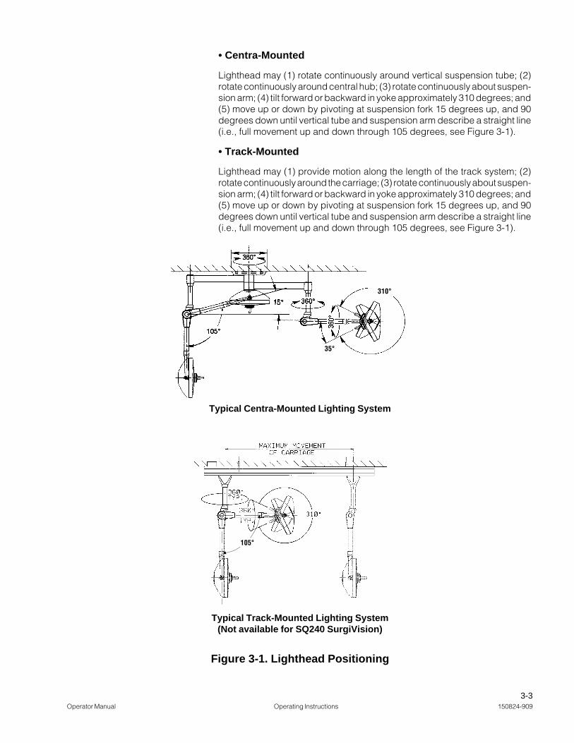
• Centra-Mounted
Lighthead may (1) rotate continuously around vertical suspension tube; (2)rotate continuously around central hub; (3) rotate continuously about suspen-sion arm; (4) tilt forward or backward in yoke approximately 310 degrees; and(5) move up or down by pivoting at suspension fork 15 degrees up, and 90degrees down until vertical tube and suspension arm describe a straight line(i.e., full movement up and down through 105 degrees, see Figure 3-1).
• Track-Mounted
Lighthead may (1) provide motion along the length of the track system; (2)rotate continuously around the carriage; (3) rotate continuously about suspen-sion arm; (4) tilt forward or backward in yoke approximately 310 degrees; and(5) move up or down by pivoting at suspension fork 15 degrees up, and 90degrees down until vertical tube and suspension arm describe a straight line(i.e., full movement up and down through 105 degrees, see Figure 3-1).
Figure 3-1. Lighthead Positioning
310°
35°
Typical Centra-Mounted Lighting System
Typical Track-Mounted Lighting System(Not available for SQ240 SurgiVision)
105°
3-4150824-909 Operating Instructions Operator Manual
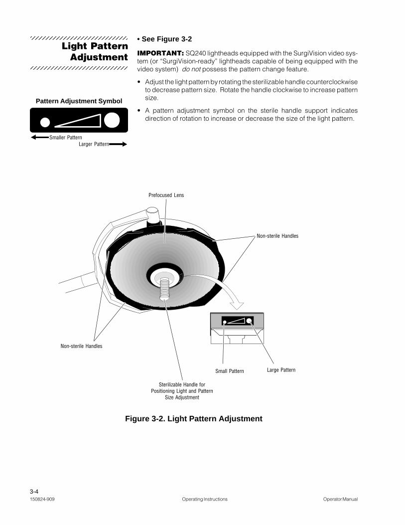
Light PatternAdjustment
• See Figure 3-2
IMPORTANT: SQ240 lightheads equipped with the SurgiVision video sys-tem (or “SurgiVision-ready” lightheads capable of being equipped with thevideo system) do not possess the pattern change feature.
• Adjust the light pattern by rotating the sterilizable handle counterclockwiseto decrease pattern size. Rotate the handle clockwise to increase patternsize.
• A pattern adjustment symbol on the sterile handle support indicatesdirection of rotation to increase or decrease the size of the light pattern.
Pattern Adjustment Symbol
Smaller PatternLarger Pattern
Figure 3-2. Light Pattern Adjustment
Sterilizable Handle forPositioning Light and Pattern
Size Adjustment
Small Pattern Large Pattern
Non-sterile Handles
Prefocused Lens
Non-sterile Handles
1234567890123456789012345678912345678901234567890123456789
1234567890123456789012345678912345678901234567890123456789

3-5Operator Manual Operating Instructions 150824-909
White NylonExtension
Sterilizable Handle
FasteningHardware(Captive)
Sterilizable HandleMounting Plate(Removable)
Replacement Handle usedwith SurgiVision Lightheads
Sterilizable Handle• Refer to Figure 3-3
The sterile handle is used to position the SQ240 lighthead and to adjust thelight pattern size.
The SurgiVision light fixture can be used without the video camera. When usedwithout the camera, an optional sterile handle fixture is attached to the cameramounting plate.
• The sterilizable handle can be removed for sterilization by unscrewing itfrom the threaded, white nylon extension.
• An optional disposable cover can be used over the sterilizable handle.(Disposable cover not supplied by STERIS.)
• The handle can be sterilized using standard hospital cycles. Alwayssterilize handle between surgical procedures.
• When reinstalling the sterilizable handle on the white, nylon extension,ensure that the handle is firmly tightened before usage.
Figure 3-3. Sterilizable Handles
White NylonExtension
Sterilizable Handle
Handle usedwith SQ240 Lightheads
Knurled-HeadMounting Screw
1234567890123456789012345678912345678901234567890123456789
1234567890123456789012345678912345678901234567890123456789
3-6150824-909 Operating Instructions Operator Manual
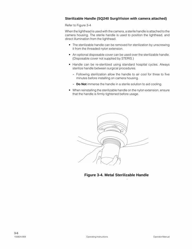
Sterilizable Handle (SQ240 SurgiVision with camera attached)
Refer to Figure 3-4
When the lighthead is used with the camera, a sterile handle is attached to thecamera housing. The sterile handle is used to position the lighthead, anddirect illumination from the lighthead.
• The sterilizable handle can be removed for sterilization by unscrewingit from the threaded nylon extension.
• An optional disposable cover can be used over the sterilizable handle.(Disposable cover not supplied by STERIS.)
• Handle can be re-sterilized using standard hospital cycles. Alwayssterilize handle between surgical procedures.
» Following sterilization allow the handle to air cool for three to fiveminutes before installing on camera housing.
» Do Not immerse the handle in a sterile solution to aid cooling.
• When reinstalling the sterilizable handle on the nylon extension, ensurethat the handle is firmly tightened before usage.
Figure 3-4. Metal Sterilizable Handle

3-7Operator Manual Operating Instructions 150824-909
• Installation
1. Rotate lighthead until lens faces the room ceiling.
2. Loosen two knurled-head thumb screws to either side of sterile handsupport, and remove sterile handle support.
3. Refer to Figures 3-5 and 3-6.
The camera is secured to the lighthead by two knurled-head thumb screws.
a. Align the camera drive gear and connector properly, and install cameraassembly to lighthead.
b. Tighten thumb screws until screw heads are snug against camerahousing. Rotate lighthead until lens and camera face room floor.
4. Position wall control circuit breaker to ON (switch should be illuminated).
5. Press the ON touch pad on the face of the wall control. (Power LED shouldbe lit.)
6. Verify that all functions of the camera operate correctly using the positioningcontrols on the wall control. Then verify functions using the wireless hand-held control (and the optional foot control, if applicable).
7. Once camera functions are verified, press the STANDBY touch pad on theface of the wall control.
8. Turn off circuit breaker when the camera is not in use.
• Removal
1. Rotate lighthead until lens faces the room ceiling.
2. Loosen two knurled-head thumb screws to either side of camera bodyand remove camera.
3. If necessary, install sterile handle support.
CAUTION: To preventcamera or replacementunit from falling, tightenthumb screws securely.
Figure 3-5. Align Camera Drive Gear andVideo Connector
Figure 3-6. Tighten Thumb ScrewsUntil Secure
Drive Gear
VideoConnector
Camera/LightheadMating Surface
Thumb Screw
Thumb Screw
CameraInstallation or
Removal
1234567890123456789012345678912345678901234567890123456789
1234567890123456789012345678912345678901234567890123456789

3-8150824-909 Operating Instructions Operator Manual
MANUALFOCUS
AUTOFOCUS
ROTATE
ZOOM
POWER
FOOT CONTROLVIDEO OUT
SVHS COMPOSITE
STANDBYON
Amsco® SQ240 SurgiVisionTM
Surgical Lighting and Video System
Connect Output toSVHS Device Here
Connect Output toComposite Device Here
General: STERIS recommends connecting a monitor approved for medicalapplications to the SQ240 SurgiVision system. The wall control provides twodifferent output signals: Composite and SVHS.
Recommended monitor for use with SQ240 SurgiVision: SONY® PVM-20M2MDU
NOTE: This SONY monitor is recommended due to its conformance withmedical safety standards, including UL 2601-1, CSA 601.1 and EN 60601-1, andis available directly from STERIS Corporation.
1. Determine the required type of output signal:
• For Composite signals, use cable P-134470-549
• For SVHS signals, use cable P-134470-550
2. Refer to the monitor's instruction manual for specific details, and connectthe appropriate cable between the wall control and the monitor.
For Hermes-ready systems, refer to the Hermes control center operatingmanual for additional monitor connections.
General: STERIS recommends connecting a Video Cassette Recorder (VCR)approved for medical applications to the SQ240 SurgiVision system. The wallcontrol provides both Composite and SVHS output signals.
Recommended VCR for use with SQ240 SurgiVision: SONY® SVO-9500MD S-VHS Videocassette Recorder.
NOTE: This SONY VCR is recommended due to its conformance with safetystandards, including UL 544, and is available directly from STERIS Corporation.
1. Determine the required type of output signal and select the appropriatecable from those provided with the VCR.
2. Refer to the VCR instruction manual for specific details, and connect theappropriate cable between the wall control and the VCR.
3. Connect monitor to VCR following instruction provided with the VCR andmonitor.
SONY® is a registered trademark of Sony Corporation of America.
Install VideoMonitor
Install VideoCassette Recorder
1234567890123456789012345678912345678901234567890123456789
1234567890123456789012345678912345678901234567890123456789
1234567890123456789012345678912345678901234567890123456789
1234567890123456789012345678912345678901234567890123456789

3-9Operator Manual Operating Instructions 150824-909
The SurgiVision camera is integrated into the sterile handle of the lighthead. Thecamera itself is provided with a metal sterilizable handle. This handle allows thecamera to be grasped and used in the same way as a standard sterile handle,both to direct light from the fixture for optimal illumination, and to position thevideo image field for the best view of the procedure.
The metal sterilizable handle must be removed from the camera and sterilizedbetween procedures. Use a general purpose hospital steam cycle to sterilizethe camera cover. Following sterilization allow the handle to air cool for threeto five minutes before installing on the camera housing. Do Not immerse thehandle in a sterile solution to aid cooling.
The SurgiVision video and control signals are turned on or off at the wall control,the wall control and the hand-held wireless control provide the same controlfunctions.
Camera functions may be controlled by three remote devices: a hand-heldwireless control, Hermes control center (verbal commands and hand-heldpendant) or an optional foot control (not available on Hermes-ready systems).
The wall control functions by transmitting signals along the main control cableto the camera located in the lighthead. The wireless control functions bytransmitting infra-red signals to the wall control. To initiate camera functionswith either control press the appropriate touch pad on the control face panel.The hand-held control's IR (infra-red) transmitter must be within approximately15 feet maximum and 50° of the wall control receiver. The control touch padsare used to control the following camera functions:
Zoom– for determining the level of detail visible in the image field. The Zoomfunction adjusts the image field continuously between two extremes:
+ (Telephoto). At extreme telephoto, the camera captures an imageshowing great detail in a small area.
NOTE: At extreme telephoto, any motion of the lighthead/camera will beexaggerated (jerky). The field of focus has little depth at this extreme,forcing the Auto Focus function (if enabled) to refocus the camera when anyobject (such as a hand) enters the image field, or if camera position isadjusted. The camera is also sensitive to light level changes at extremetelephoto.
– (Wide Angle). At extreme wide angle, the camera captures a large,image with less detail than telephoto.
NOTE: At extreme wide angle, the image field possesses a greater depthof focus and less sensitivity to light level changes.
Rotate–Use this function to change orientation of the video field. Image fieldcan be rotated in either clockwise or counter-clockwise directions.
Manual FocuManual FocuManual FocuManual FocuManual Focus–s–s–s–s–Use this function to manually set the focus for close-up shotsor other special applications. The Auto Focus function must be toggled off toenable manual focusing. Adjust the clarity of focus by pressing the + or –touchpads.
NOTE: + touch pad moves the lens slightly CLOSER to subject; – touch padmoves the lens slightly AWAY from subject.
SurgiVisionCamera Operation
» Wall Control andWireless Hand-held
Control Functions
Metal Sterilizable Handle
1234567890123456789012345678912345678901234567890123456789
1234567890123456789012345678912345678901234567890123456789

3-10150824-909 Operating Instructions Operator Manual
Figure 3-8. Optional Foot control
Control Cable Connects toKeyed Jack on Bottom of Wall
ControlActivate Foot Control
Functions by Pressing onAppropriate Side of Foot
Pedals.
MANUALFOCUS
AUTOFOCUS
ROTATE
ZOOM
POWER
FOOT CONTROLVIDEO OUT
SVHS COMPOSITE
STANDBYON
Amsco® SQ240 SurgiVisionTM
Surgical Lighting and Video System
Wall Control
Hand-Held Wireless Control
Figure 3-7. SurgiVision Controls
Control Touch Pad
Infrared Transmitter
Infrared Receiver
Video SystemON/STANDBY
SwitchesCircuit Breaker
Zoom:"+" close (tight)"-" far (wide)Rotate:
" " counterclockwise
" " clockwise Manual Focus:"+" moves lens closer to subject"-" moves lens further from subject
Control Touch Pad
Auto Focus:Automatic lensmovement controlledby camera.

3-11Operator Manual Operating Instructions 150824-909
Auto Focus–Use this function to toggle Auto Focus on or off. When Auto Focusis ON, the camera automatically focuses on the object in the image field closestto the camera lens. When Auto Focus is turned OFF, the camera maintainsfocus on the last object upon which it was focused, until Auto Focus is turnedback on.
NOTE: It may be necessary to toggle Auto Focus OFF when using the cameraat extreme telephoto (or close up), to prevent the camera from refocusing onhands and other objects introduced into the image field during the shot.
HERMES-Ready Control Center–The Hermes Control Center functions bytransmitting signals through a interface cable connected to the wall control.When used, the interface cable should be routed to avoid surgical personnelfoot traffic. The control center is intended to allow personnel within the sterilefield to operate all camera functions using verbal commands or a hand-heldpendant. Refer to the Hermes operating manual for more information.
The foot control functions by transmitting signals through a cable connectedto the wall control. When the foot control is used, the cable should be routedto avoid surgical personnel foot traffic. The foot control is intended to allowpersonnel within the sterile field to operate the zoom and rotation functions ofthe camera.
Foot control is used to control zoom and rotation functions. Press onappropriate sides of foot pedals to activate foot control functions. Functionscontrolled through the foot control unit are identical to those controlled throughthe hand-held wireless control or wall control. See Figure 3-8.
» Optional Foot Control
The following steps will aid in maximizing video imaging effectiveness.
• Energize the light at setting 3 on the variable intensity controller (VIC), andposition the lighthead approximately 42" (1067 mm) from the surgical site.
• Using the hand-held remote, or the wall control, zoom in or out (+ or -) untilthe desired image fills the viewing screen of the monitor.
NOTE: Zooming completely out causes image distortion within the illuminatedarea.
If the light pattern (white circle) does not fill the monitor’s screen (shadedsquare), the image inside the pattern will be distorted.
Reposition the camera to orient the focal point (center of the desired image)at the center of the viewing screen.
Adjust zoom and rotation as needed:
• The camera may be zoomed to the full 12x zoom and rotation orientationadjusted as needed.
• Clockwise and/or counterclockwise orientation is adjusted by using thecurved arrow(s) on the hand-held control, the wall control or the optional footcontrol.
» Guidelines forMaximizing Video Image
123456789012345678901234567890121234567891234567890123456789012345678901212345678912345678901234567890123456789012123456789123456789012345678901234567890121234567891234567890123456789012345678901212345678912345678901234567890123456789012123456789123456789012345678901234567890121234567891234567890123456789012345678901212345678912345678901234567890123456789012123456789123456789012345678901234567890121234567891234567890123456789012345678901212345678912345678901234567890123456789012123456789123456789012345678901234567890121234567891234567890123456789012345678901212345678912345678901234567890123456789012123456789123456789012345678901234567890121234567891234567890123456789012345678901212345678912345678901234567890123456789012123456789123456789012345678901234567890121234567891234567890123456789012345678901212345678912345678901234567890123456789012123456789123456789012345678901234567890121234567891234567890123456789012345678901212345678912345678901234567890123456789012123456789123456789012345678901234567890121234567891234567890123456789012345678901212345678912345678901234567890123456789012123456789123456789012345678901234567890121234567891234567890123456789012345678901212345678912345678901234567890123456789012123456789123456789012345678901234567890121234567891234567890123456789012345678901212345678912345678901234567890123456789012123456789123456789012345678901234567890121234567891234567890123456789012345678901212345678912345678901234567890123456789012123456789123456789012345678901234567890121234567891234567890123456789012345678901212345678912345678901234567890123456789012123456789123456789012345678901234567890121234567891234567890123456789012345678901212345678912345678901234567890123456789012123456789
Monitor's Screen (Image Area)
Light Pattern(Illuminated Area)

3-12150824-909 Operating Instructions Operator Manual
As instruments are introduced and removed from the surgical field, the autofocus will attempt to focus on the nearest object, causing the image to blurintermittently. To prevent his effect, once the camera has been positioned andfocused onto the surgical site, the manual focus mode may be engaged tomaintain image clarity during the procedure.
For deep cavity illumination, it may be necessary to engage the manual focusto focus beyond the nearest object (i.e., the surface area surrounding theincision) so that the desired image can be viewed clearly.
» Engage Manual Focus(Optional)

4-1Operator Manual Cleaning the Equipment 150824-909
• Pail
• Sponge
• Cloth Wipes
• Rubber Gloves
• Mild Household Detergent (e.g., Joy)
• Disinfectant cleaners such as:
» Coverage® Spray TB (1424-63)
» Germicidal Cloth (NK350, NK352)
» Coverage® Spray HB (1424-63)
» Coverage® HB Concentrate (1420-08)
» T.B.Q.® (6345-08)
» Coverage Plus® (6367-08)
All listed disinfectant cleaning products are available from STERIS for useon this equipment.
WARNING - PERSONALINJURY HAZARD: Do notattempt to clean lightheadunless power is turned offat variable intensitycontroller by disengagingthe circuit breaker(s) andthe lighthead has cooledsufficiently.
Use of any disinfectant so-lution other than thoselisted below may cause dis-coloration or deformationon the acrylic lens surface:Coverage Spray TB, Ger-micidal Cloth, CoverageSpray HB, Coverage HBConcentrate, T.B.Q., orCoverage Plus. Cleaningsolutions other than thoselisted have NOT been testedfor compatibility or effec-tiveness. Always followmanufacturer instructionsfor concentrations and useof cleaning products.
CLEANING THE EQUIPMENT 4
CleaningEquipment
1234567890123456789012345678912345678901234567890123456789
1234567890123456789012345678912345678901234567890123456789

4-2150824-909 Cleaning the Equipment Operator Manual
General Cleaning/Disinfecting
Procedure
1. Wear rubber gloves
2. Use sponge and a mild detergent and water solution. The followingcleaning/disinfecting agents are compatible with the outer surfaces of thesuspension arm, yoke, lighthead and acrylic lens when used in accordancewith label instructions: Coverage Spray TB, Germicidal Cloth, CoverageSpray HB, Coverage HB Concentrate, T.B.Q., or Coverage Plus.
3. Prepare cleaning or disinfecting solution in accordance with directions onthe container labels.
4. Using a soft cloth and the cleaning solution, thoroughly wipe the areas tobe cleaned (see Figure 4-1). Make sure to wring out excess solutionbefore wiping.
5. Rinse all surfaces with a soft cloth wipe and clear water.
6. Wipe all surfaces dry with a clean, dry cloth.
7. Ensure sterile camera cover or sterile handle is sterilized between eachprocedure using a standard hospital cycle.
Cleaning Hand-held Control
Clean the hand-held control once a day, or as needed between procedures.
1. Soak a soft cloth in a solution of water and a recommended agent. Wringthe cloth until excess moisture has been eliminated.
2. Wipe all surfaces of the hand-held control, removing any accumulateddebris or soil.
3. Using a clean, dry cloth, wipe the surfaces of the control untilcompletely dry.
WARNING - PERSONALINJURY HAZARD: Do notattempt to clean lightheadunless power is turned offat variable intensity con-troller by disengaging thecircuit breaker(s) and thelighthead has cooledsufficiently.
CAUTION: Use of any dis-infectant solution otherthan those listed belowmay cause discolorationor deformation on theacrylic lens surface: Cov-erage Spray TB, Germi-cidal Cloth, CoverageSpray HB, Coverage HBConcentrate, T.B.Q., orCoverage Plus. Cleaningsolutions other than thoselisted have NOT beentested for compatibility oreffectiveness. Alwaysfollow manufacturerinstructions for concen-trations and use ofcleaning products.
CAUTION: Do notimmerse the hand-heldcontrol in fluid.
1234567890123456789012345678912345678901234567890123456789
1234567890123456789012345678912345678901234567890123456789
4-3Operator Manual Cleaning the Equipment 150824-909
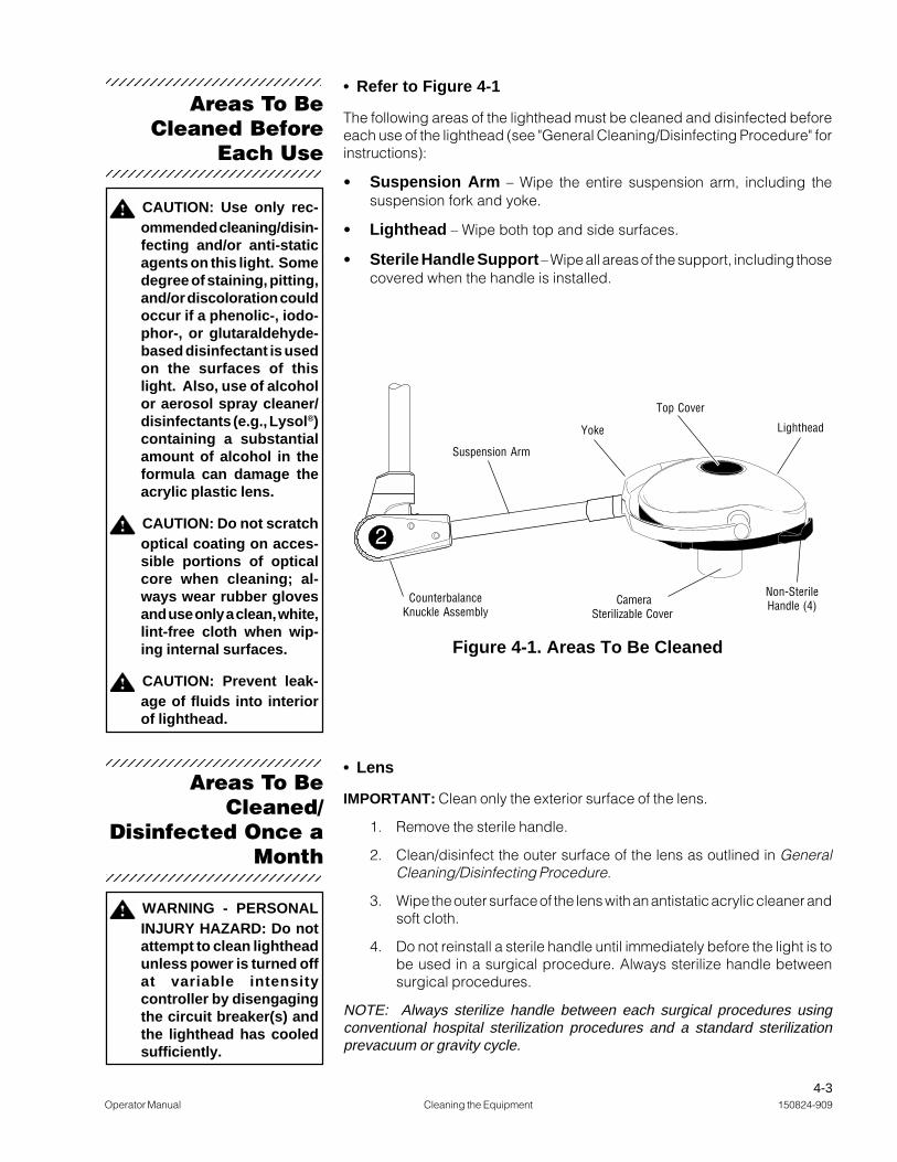
• Refer to Figure 4-1
The following areas of the lighthead must be cleaned and disinfected beforeeach use of the lighthead (see "General Cleaning/Disinfecting Procedure" forinstructions):
• Suspension Arm – Wipe the entire suspension arm, including thesuspension fork and yoke.
• Lighthead – Wipe both top and side surfaces.
• Sterile Handle Support – Wipe all areas of the support, including thosecovered when the handle is installed.
Areas To BeCleaned Before
Each Use
CAUTION: Use only rec-ommended cleaning/disin-fecting and/or anti-staticagents on this light. Somedegree of staining, pitting,and/or discoloration couldoccur if a phenolic-, iodo-phor-, or glutaraldehyde-based disinfectant is usedon the surfaces of thislight. Also, use of alcoholor aerosol spray cleaner/disinfectants (e.g., Lysol®)containing a substantialamount of alcohol in theformula can damage theacrylic plastic lens.
CAUTION: Do not scratchoptical coating on acces-sible portions of opticalcore when cleaning; al-ways wear rubber glovesand use only a clean, white,lint-free cloth when wip-ing internal surfaces.
CAUTION: Prevent leak-age of fluids into interiorof lighthead.
WARNING - PERSONALINJURY HAZARD: Do notattempt to clean lightheadunless power is turned offat variable intensitycontroller by disengagingthe circuit breaker(s) andthe lighthead has cooledsufficiently.
Areas To BeCleaned/
Disinfected Once aMonth
Lighthead
Top Cover
Figure 4-1. Areas To Be Cleaned
Non-SterileHandle (4) Camera
Sterilizable Cover
Yoke
Suspension Arm
CounterbalanceKnuckle Assembly
• Lens
IMPORTANT: Clean only the exterior surface of the lens.
1. Remove the sterile handle.
2. Clean/disinfect the outer surface of the lens as outlined in GeneralCleaning/Disinfecting Procedure.
3. Wipe the outer surface of the lens with an antistatic acrylic cleaner andsoft cloth.
4. Do not reinstall a sterile handle until immediately before the light is tobe used in a surgical procedure. Always sterilize handle betweensurgical procedures.
NOTE: Always sterilize handle between each surgical procedures usingconventional hospital sterilization procedures and a standard sterilizationprevacuum or gravity cycle.
1234567890123456789012345678912345678901234567890123456789
1234567890123456789012345678912345678901234567890123456789
1234567890123456789012345678912345678901234567890123456789
1234567890123456789012345678912345678901234567890123456789

5-1Operator Manual Operator Troubleshooting P-150824-909
WARNING - PERSONALINJURY HAZARD: Donot attempt to replacethe lamp unless poweris turned off at variableintensity controller bydisengaging the circuitbreaker(s) and the light-head has cooled suffi-ciently.
WARNING - PERSONALINJURY HAZARD: Donot attempt to cleanlighthead unless poweris turned off at variableintensity controller bydisengaging the circuitbreaker(s) and the light-head has cooled suffi-ciently.
WARNING - PERSONALINJURY HAZARD:Do not attempt to adjustsuspension system. Re-fer servicing to qualifiedservice personnel.
PROBLEM POSSIBLE CAUSE AND/OR CORRECTION
1. Lighthead driftsonce set inposition andreleased.
1. Brake adjustment incorrect — call your service representative, or — ifqualified — consult section concerning suspension arm adjustments inMaintenance Manual P-764326-998.
2. Centra Mount not level — call your service representative, or — ifqualified — consult section concerning suspension arm adjustments inMaintenance Manual P-764326-998.
3. Centra Mount Units — Track Mount not level — call your servicerepresentative, or — if qualified — consult Section concerningsuspension arm adjustments in Maintenance Manual P-764326-998.
5OPERATOR TROUBLESHOOTING
Use the following Troubleshooting Chart to identify problems and probablecauses should they occur.
If you are unable to correct the problem with this Troubleshooting Chart, or ifa problem occurs not described on the chart, please call your STERISrepresentative, who will arrange to have your equipment promptly put intoworking order by a factory-trained representative. Never permit unquali-fied persons to service the lightheads or suspension arms.
2. Light flickerswhen moved.
1. Possible contact problem at yoke commutator, horizontal/vertical armcommutator, or centra hub commutator— contact STERIS Service.
2. Track Mount Units — Possible contact problem with electrical brushes(at carriage; internal and external brushes; and at the yoke/horizontalarm assembly; commutator assembly)—contact STERIS Service.

5-2P-150824-909 Operator Troubleshooting Operator Manual
PROBLEM POSSIBLE CAUSE AND/OR CORRECTION
3. Light will not turn on.
1. Inspect lamp change mechanism to ensure secondary lamp has intactfilament, or is fully seated in socket.
2. If lamps appear operable, refer problem to qualified STERIS or STERIS-trained service technician.
4. Lamp changemechanism willnot work.
1. Bent lamp filament; lightheads knocked together while lit — check lampfilament position. Replace lamp if bent.
5. Poor light pattern.
7. Video systemdoes not respondto commandsfrom hand-heldwireless control oroptional footcontrols.
1. Hand-held Wireless control:
• Check batteries in hand-held wireless control.
• Ensure wall control receiver is not covered.
2. Foot Control:
• Check connection of foot control cable to wall control.
1. Refer problem to qualified STERIS or STERIS-trained service technician.6. Light pattern willnot change.
1. Possible malfunctions at variable intensity controller — check circuitbreakers and turn ON if tripped to OFF.
2. Check fuses — replace if failed.
IMPORTANT: If fuses fail again immediately, call your servicerepresentative. Do not attempt to use the light.
3. Both lamps in lamp change mechanism may have failed — replace iffailed. Lamp failure LEDs on lighthead will be blinking if both lamps havefailed.
8. Video systemdoes not respondto verbalcommands orhand-heldpendant.
1. Check Hermes interface cable connection from Hermes control center towall control (refer to Hermes control center operating manual).

6-1Operator Manual Maintenance 150824-909
SCHEDULE
Procedure Frequency Paragraph (if applicable**)
Inspect lamp change mechanism and lamp each inspection Inspect Lamp Change Mechanism
Change secondary lamp every year Lamp Replacement
Check for movement in vertical suspension each inspection Check Vertical Suspension Tubetube and for red band at top of verticalsuspension tube.
Ensure all three yoke plug buttons are each inspectionsecurely seated and tethered
Check light pattern and illumination levels every year
Inspect lighthead and arm wiring for every 6 monthsdeterioration
Inspect arm assembly for ease of each inspectionmovement
Ensure force required to raise and lower each inspectionarm is similar
Check suspension system for drift each inspection
Ensure Centra hub rubber cap is secure each inspection Check Hub Cap (Centra Mount)
Check variable intensity control each inspection Check Light Intensity Control
Ensure lighthead moves through entire each inspection Lighthead Positioningrange of articulation
Check battery backup option (if applicable) each inspection Check Battery Backup
Check camera controls for smooth every 6 monthsmovement and full range of motion.
• Verify proper operation of zoomcontrols
• Verify proper operation of rotationcontrols
• Verify Manual Focus and Auto Focus
(ON/OFF and function)
• Check batteries in remote control
• Check operation of optional footcontrol (if applicable)
MAINTENANCE
NOTE: This schedule is supplied for the customer’s reference only, any actualservice should be done by a qualified service technician.
These procedures should be performed at regular intervals as indicated. Thisfrequency is minimum and should be increased with increased light usage.
6
PreventiveMaintenance
Record
1234567890123456789012345678912345678901234567890123456789
1234567890123456789012345678912345678901234567890123456789

6-2150824-909 Maintenance Operator Manual
SCHEDULE
Procedure Frequency Paragraph (if applicable**)
Verify secure mechanical attachment of each inspectioncamera assembly to mounting plate.
Verify security of electrical connections each inspectionbetween the wall control and camera
Verify secure attachment of sterile handle each inspectionassemblies to lighthead, includingreplacement handle of camera mount.
Inspect camera lens, clean if necessary. each inspection
Inspect plug buttons or other components each inspectionthat may attach to the camera or arm
** When no paragraph is listed, operation should be performed by or referred to STERIS service representative (or otherqualified technician). Refer to Maintenance Manual P-764326-998.
NOTE: Any repairs or adjustments to lighthead and its suspension system should only be made by qualified STERISor STERIS trained service personnel while referring to Maintenance Manual P-764326-998.

6-3Operator Manual Maintenance 150824-909
• Refer to Figure 6-1
1. The lamp change mechanism assembly is accessed by removing thesterilizable handle, if present. Loosen the four quarter-turn, wing-headfasteners and carefully lower camera or handle mount until the lampchange mechanism is visible. The assembly pivots to the side, allowingaccess to the lamps. The active lamp is positioned higher, and toward thecenter of the assembly.
2. Inspect the lamps for damage or discoloration. Be sure the element of thelamp in the secondary position is intact. Replace if necessary.
3. Check that lamps are firmly seated in their sockets.
4. Raise the lamp change mechanism into the lighthead and secure quarter-turn, wing-head mounting fasteners. Do not re-install the sterilizablecamera cover or sterilizable handle until the fixture is to be used. (Sterilizehandle, before returning to light.)
Inspect LampChange Mechanism
WARNING - PERSONALINJURY HAZARD: Do notattempt to replace thelamp unless power isturned off at variable in-tensity controller by dis-engaging the circuitbreaker(s) and the light-head has cooled suffi-ciently.
CAUTION: Do not touchglass portion of lampduring re-lamping orcleaning.
CAUTION: Manual ac-tuation of the lampchange mechanism mayresult in permanent dam-age to the gear motor.
• Refer to Figure 6-2
1. Inspect vertical suspension tube. A red colored band has been applied tothe surface of the tube normally hidden under the rubber boot at the top ofthe tube. If the mounting configuration has been properly assembled, thered band will not be visible. If the red band is visible, do not attempt to usethe light fixture. Call your STERIS service representative immediately.
2. Attempt to push the vertical suspension tube back and forth or side to side.If the tube “wobbles,” mounting configuration has not been assembledcorrectly. Call your STERIS service representative immediately.
3. Loosen screw and pull the lower plastic cap on the vertical tube away fromthe top of the suspension fork. Inspect the four bolts at the bottom of thetube. If any bolts have become loose, tighten them and replace the cap.
Check VerticalSuspension Tube
WARNING - PERSONALINJURY HAZARD: Do notuse lighting fixture if redband is visible below rub-ber cap at top of verticalsuspension tube.
Check BatteryBackup
(as applicable)
1. Turn on light.
2. Turn off AC power to Variable Intensity Controller.
3. Check that the battery backup indicator LED's and light are still on.
4. Restore AC power and check that the indicator LED's have gone out.
WARNING - ELECTRICSHOCK HAZARD: Do notremove variable intensitycontroller covers referservicing to qualified ser-vice personnel.
1234567890123456789012345678912345678901234567890123456789
1234567890123456789012345678912345678901234567890123456789
1234567890123456789012345678912345678901234567890123456789
1234567890123456789012345678912345678901234567890123456789
1234567890123456789012345678912345678901234567890123456789
1234567890123456789012345678912345678901234567890123456789

6-4150824-909 Maintenance Operator Manual
Figure 6-2. Check Vertical Suspension Tube
Figure 6-3. Check Yoke Plug Button
Figure 6-1. Inspect Lamp Change Mechanism
SecondaryLamp
PrimaryLamp
Ensure that the vertical suspension tube cannot move back-and-forth or side-to-side.
INCORRECT(Red Band Showing)
CORRECT(No Red Band)
Yoke Plug Button
Video Camera
CORRECT(No Red Band)
6-5Operator Manual Maintenance 150824-909
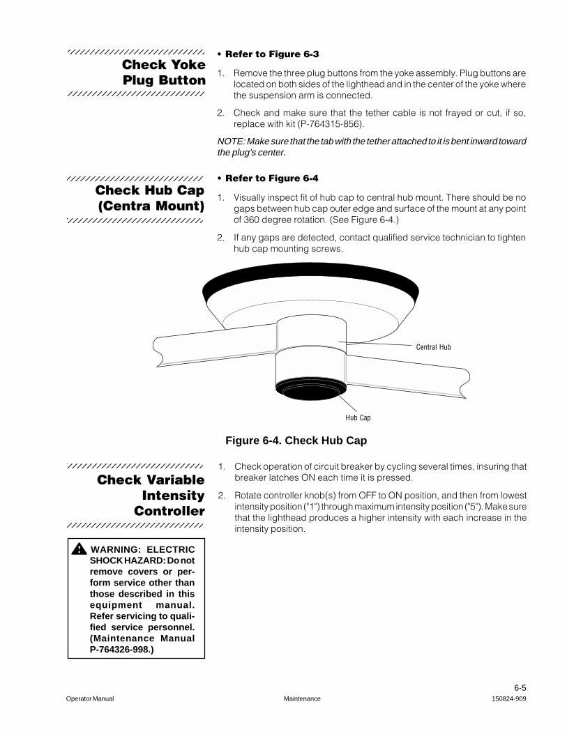
• Refer to Figure 6-4
1. Visually inspect fit of hub cap to central hub mount. There should be nogaps between hub cap outer edge and surface of the mount at any pointof 360 degree rotation. (See Figure 6-4.)
2. If any gaps are detected, contact qualified service technician to tightenhub cap mounting screws.
Figure 6-4. Check Hub Cap
Central Hub
Hub Cap
Check Hub Cap(Centra Mount)
1. Check operation of circuit breaker by cycling several times, insuring thatbreaker latches ON each time it is pressed.
2. Rotate controller knob(s) from OFF to ON position, and then from lowestintensity position ("1") through maximum intensity position ("5"). Make surethat the lighthead produces a higher intensity with each increase in theintensity position.
Check VariableIntensity
Controller
WARNING: ELECTRICSHOCK HAZARD: Do notremove covers or per-form service other thanthose described in thisequipment manual.Refer servicing to quali-fied service personnel.(Maintenance ManualP-764326-998.)
Check YokePlug Button
• Refer to Figure 6-3
1. Remove the three plug buttons from the yoke assembly. Plug buttons arelocated on both sides of the lighthead and in the center of the yoke wherethe suspension arm is connected.
2. Check and make sure that the tether cable is not frayed or cut, if so,replace with kit (P-764315-856).
NOTE: Make sure that the tab with the tether attached to it is bent inward towardthe plug's center.
1234567890123456789012345678912345678901234567890123456789
1234567890123456789012345678912345678901234567890123456789
1234567890123456789012345678912345678901234567890123456789
1234567890123456789012345678912345678901234567890123456789
1234567890123456789012345678912345678901234567890123456789
1234567890123456789012345678912345678901234567890123456789

6-6150824-909 Maintenance Operator Manual
• Refer to Figure 6-5 and 6-6
Each lighthead is equipped with two lamps. One of these lamps, called theprimary, is always positioned at a point in the optical core to provide best focusand illumination. When the primary lamp fails, a secondary lamp lightsimmediately and automatically moves to replace the primary lamp, yieldingequivalent optical performance. In this process, transmission of light to theoperating table is interrupted for less than one second.
If one lamp in the lighthead fails, the failure is indicated by a blinking LED onthe side of the outer cover. Do not allow the lighthead to operate for any lengthof time with only one functional lamp. Always replace a failed lamp at theearliest opportunity. Primary lamp returns to position after it is replaced.
IMPORTANT: The procedure for accessing the lamps is slightly different,depending on the type of lighthead. Types of lightheads can be separated intotwo categories:
• SQ240 Lightheads (or SurgiVision lightheads without camera installed), or
• SurgiVision lightheads with camera installed.
To replace a failed lamp, complete the appropriate procedure below:
Lamp Replacement
WARNING: ELECTRICSHOCK HAZARD: Donot remove covers orperform service otherthan as described in thisequipment manual. Re-fer servicing to qualifiedservice personnel.(Maintenance Manual P-764326-998.)
WARNING - PERSONALINJURY HAZARD: Donot attempt to replacethe lamp unless poweris turned off at variableintensity controller bydisengaging the circuitbreaker(s) and the light-head has cooled suffi-ciently.
CAUTION: Do not touchglass portion of lampduring e-l-amping orcleaning.
CAUTION: Manual actua-tion of the lamp changemechanism may result inpermanent damage to thegear motor.
» Lamp ReplacementProcedure for SQ240
lightheads orSurgiVision
Lightheads withoutCamera installed
1. Turn OFF power to the lighthead at the circuit breaker on the variableintensity controller.
2. Remove sterilizable handle, if present.
3. Loosen four quarter-turn fasteners.
4. Lower lamp change mechanism through circular aperture in the center ofthe lens. The assembly pivots to the side, allowing access to the lamps.Refer to Figure 6-5.
5. Normally, the failed lamp is in the lower of the two lamp sockets in thelighthead. Remove failed lamps and replace with new lamps.
• If fixture provides no light at all, and LEDs on outer cover of lightheadare blinking, both lamps may have failed.
Remove each failed lamp by grasping the socket in one hand and thelamp base in the other, then gently move the lamp base back-and-forthwhile pulling it from the socket.
NOTE: Grasp the lamp base and lamp socket firmly when installing a newlamp to prevent movement of the lamp change mechanism. Manualactuation may cause permanent damage to the gear motor.
6. Grasp the new lamp by its ceramic base (do not remove protective wrapperdo not touch glass) and press into the lower lamp holder. After replacingeither lamp, remove wrapper(s) and inspect both lamps to ensure bothhave intact filaments.
1234567890123456789012345678912345678901234567890123456789
1234567890123456789012345678912345678901234567890123456789

6-7Operator Manual Maintenance 150824-909
LoosenFasteners
Lower the LampChange Mechanism
Secondary Lamp
Primary Lamp
Lamp Socket
Figure 6-5. Lamp Replacement Procedure for SQ240 Lightheads or SurgiVisionLightheads without Camera installed

6-8150824-909 Maintenance Operator Manual
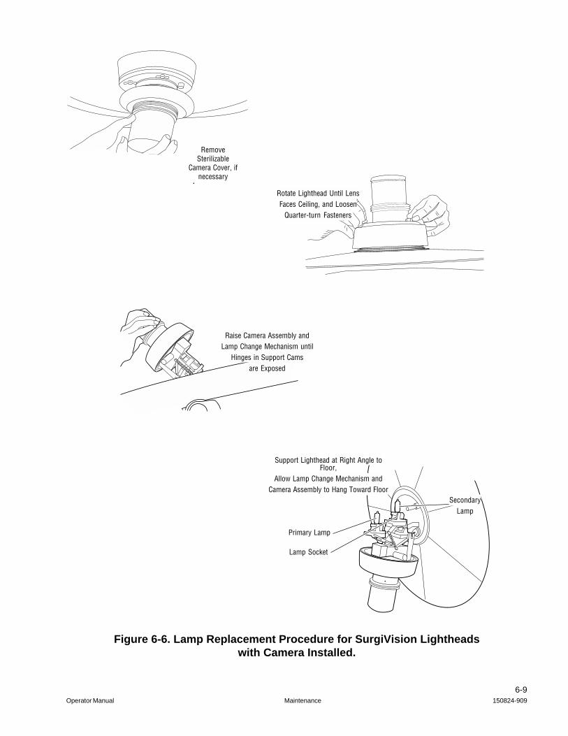
1. Turn OFF power to the lighthead at the circuit breaker on the variableintensity controller.
2. Turn off power to the camera by pressing the STANDBY button on theSurgiVision wall control, if present.
3. Remove sterilizable camera handle, if present.
4. Rotate lighthead until lens faces ceiling.
5. Loosen four quarter-turn fasteners around the base of the camera.
6. Grasp camera body and raise assembly out of lighthead until hinges insupport cams are exposed.
7. Rotate lighthead approximately 90 and gently lower lamp changemechanism and camera assembly until it rests against the face of the lens.Refer to Figure 6-6.
NOTE: Next step may required the assistance of a second person to steadythe lighthead.
8. Normally, the failed lamp is in the lower of the two lamp sockets in thelighthead. Remove failed lamps and replace with new lamps.
• If fixture provides no light at all, and LEDs on outer cover of lightheadare blinking, both lamps may have failed.
Remove failed lamps by grasping the socket in one hand and the lampbase in the other, then gently move the lamp base back-and-forth whilepulling it from the socket.
NOTE: Grasp the lamp base and lamp socket firmly when installing a newlamp to prevent movement of the lamp change mechanism. Manualactuation may cause permanent damage to the gear motor.
9. Grasp the new lamp by its ceramic base (do not remove protective wrapperdo not touch glass) and press into the lower lamp holder. After replacingeither lamp, remove wrapper(s) and inspect both lamps to ensure bothhave intact filaments.
10. Return the lamp change mechanism into the lighthead, and tighten quarter-turn fasteners. Do not re-install the sterilizable camera cover until the fixtureis to be used. (Sterilize camera cover, if necessary, before returning tolight.)
7. Raise the lamp change mechanism into the lighthead, and tighten quarter-turn fasteners. Do not re-install the sterilizable handle until the fixture is tobe used. (Sterilize handle, if necessary, before returning to light.)
8. Return power to lighthead by pressing the circuit breaker at VariableIntensity Controller to ON.
9. Verify that the Lamp Failure LEDs are not blinking. If the LEDs are stillblinking, access lamp change mechanism again and examine the filamentsof both lamps to ensure that one was not damaged during the lampreplacement procedure.
» Lamp ReplacementProcedure for
SurgiVisionLightheads with
Camera installed
CAUTION: Do not touchglass portion of lampduring re-lamping orcleaning.
CAUTION: Manual actua-tion of the lamp changemechanism may result inpermanent damage to thegear motor.
6-9Operator Manual Maintenance 150824-909
Figure 6-6. Lamp Replacement Procedure for SurgiVision Lightheadswith Camera Installed.
Support Lighthead at Right Angle toFloor,
Allow Lamp Change Mechanism andCamera Assembly to Hang Toward Floor
SecondaryLamp
Primary Lamp
Lamp Socket
Rotate Lighthead Until LensFaces Ceiling, and Loosen
Quarter-turn Fasteners
RemoveSterilizable
Camera Cover, ifnecessary
Raise Camera Assembly andLamp Change Mechanism until
Hinges in Support Camsare Exposed

6-10150824-909 Maintenance Operator Manual
11. Return power to lighthead by pressing the circuit breaker at VariableIntensity Controller to ON.
12. Verify that the Lamp Failure LEDs are not blinking. If the LEDs are stillblinking, access lamp change mechanism again and examine the filamentsof both lamps to ensure that one was not damaged during the lampreplacement procedure.

7-1Operator Manual Replacement Parts 150824-909
RecommendedDescription Part Number Spares
Fuse 20 Amp P-129362-213 5Lamp P-129362-228 3Sterilizable Handle P-93184-001 3Sterilizable Camera Cover P-134470-429 2• Quartz Lens Only P-134470-447 2• Housing Only P-056938-816 1Hermes Interface Cable P-134469-380 1
Associated Publications Part Number
Uncrating Instructions (Centra Mount) P-129362-443Installation Instructions (Centra Mount) P-150824-819Maintenance Manual P-764326-998Uncrating Instructions (SQ-Track Mount) P-150824-929Installation Instructions (SQ-Track Mount) P-150824-930
Equipment DrawingsSQ240 Centra Mounted, One 36" Arm, One Lighthead P-129378-078SQ240 Centra Mounted, Two 36" Arms, Two Lightheads P-129378-079SQ240 Centra Mounted, Three 36" Arms, Three Lightheads P-129378-080
Equipment Drawings (Wall Mounted Controls)
SQ240 Single, Surface Mounted VIC P-150824-833SQ240 Single, Recess Mounted VIC P-150824-834SQ240 Dual, Surface Mounted VIC P-150824-835SQ240 Dual, Recess Mounted VIC P-150824-836SQ240 SurgiVision Wall Control Mount P-129378-082
Parts listed in this section are those that would be necessary to do minormaintenance on the lighting fixture. Quantities listed are the minimum numberof spares that we recommend you keep on hand.
When ordering, please include the part number, description, and quantity foreach replacement part requested.
Send your order directly to your nearest STERIS Regional Office.
REPLACEMENT PARTS 7
Continued on next page

7-2150824-909 Replacement Parts Operator Manual
Associated Publications Part Number
Equipment Drawings (Centra Mounted Fixture)
SQ240 Centra Mounted, One 36" Arm, One Lighthead P-150824-837SQ240 Centra Mounted, Two 36" Arms, Two Lightheads P-150824-838SQ240 Centra Mounted, One 24" Arm & One 36" Arm,
Two Lightheads P-150824-948SQ240 Centra Mounted, Three 36" Arms, Three Lightheads P-150824-839SQ240 Centra Mounted, One 36" Arm, One Lighthead
(with provision for future lighthead addition) P-150824-840SQ240 Centra Mounted, Two 36" Arms, Two Lightheads
(with provision for future lighthead addition) P-150824-841
Equipment Drawings (Track Mounted Fixture)SQ240 4'6" Surface Mounted Track, One Lighthead P-150824-922SQ240 4'6" Recessed Mounted Track, One Lighthead P-150824-923SQ240 9' Surface Mounted Track, One Lighthead P-150824-924SQ240 9' Recessed Mounted Track, One Lighthead P-150824-925SQ240 9' Surface Mounted Track, Two Lightheads P-150824-944SQ240 9' Recessed Mounted Track, Two Lightheads P-150824-945