operator & parts manual - degelmandegelman.com/assets/manuals/143368-pro-till-33-40.pdf ·...
TRANSCRIPT

PRO-TILL 33/40& PRO-TILL 40 (Controlled Traffic)
Serial Numbers: 1728 and above
OPERATOR & PARTS MANUAL
D E G E L M A N I N D U S T R I E S L T D.B O X 8 3 0 - 2 7 2 I N D U S T R I A L D R I V E ,R E G I N A , S K , C A N A D A , S 4 P 3 B 1FA X 306.543.2140 P H 3 0 6 . 5 4 3 . 4 4 4 71 . 8 0 0 . 6 6 7 . 3 5 4 5 D E G E L M A N . C O M
143368 v1.4


3
5
3
4 2222 4
1 111
* Refer to operators manual for complete safety and operation info.
Grease Points• Front Frame / Rockshaft Pins
• Wing Frame Pins
• Cylinder Pins
• Wing Transport Roller Pins
• Hubs & Spindles
• Working points & pins
Maintenance (Check Machine Daily)
A Connect Hydraulics
WHEELSROLLERSTRANSPORTWINGSJACK
3
5
4
2
1
5
41
32
FLOAT FLOAT
(if available)
143349 v1.2
QUICK-START GUIDE*
for PRO-TILL 33/40* Refer to operators manual for complete safety and operation info.
TO BE ELIGIBLE FOR
YOU MUST REGISTER
WARRANTY
REMEMBER! You must complete ProductRegistration to be eligible for Warranty.

B Put in Field Position
3
iv)
v)
4
3
3 3
3
i)
ii)
iii)
1”
3
44
F MAX Transport Speed: 40 km/h (25 MPH)
E Lower Wheels for Headland Turns.1
C Set Cutting Depth
Typically Set to 2”
Typically Set to 2”
Front Disc Depth Adjustment Rear Disc Depth Adjustment(2 Inner Wheel Cylinders) (2 Outer Roller Frame Cylinders) 21
(Start with 12 stops per cylinder, test depth & adjust)
(IMPORTANT: Add depthstops starting from rod end)
Scraper Position Overview (Rubber Rollers)
Set Gapdistance at
1/4” to 3/8”from roller surface.
Storage Position
Maintenance Position
Engaged Position
Remove the 4 bolts to rotate intoor out of “Storage position”,then re-install.
Loosen the 4 bolts to rotate up into “Maintenance
Position” & secure.
Loosen the 4 bolts to rotate downward.
Set the scraper clearance
(1/4” to 3/8”). Properly tighten.
D Test. Check. Adjust.10-12 MPH
100m
(Ideal Operating Speed)

1. Position trailer on level ground with lots of room on the unloading side for unloading and driving unit of trailer.
2. Use appropriate forklifts to unload front “A” frame hitch, hardware container, and unloading ramps from trailer.
3. Position the four unloading ramps on unloading side of trailer at each tire location.
4. Position tractor near but to the side of the raised hitch frame on the main assembly. Connect the hoses for the two main transport cylinders (#4) and lower the hitch frame.
5. Position and support the front “A” frame hitch in front of the lower frame section. Use the 1” x 4-1/2” GR8 bolts and hardware from the shipping container to re-attach the frame sections.
Torque as required: 770 lb.ft (1050 N.m)
6. Re-route, secure and connect all hydraulic hoses and wiring onto the main frame.
7. Hook up to an appropriately sized tractor and properly secure with clevis hitch and safety chain.
DANGER: NEGATIVE TONGUE WEIGHT/ TIP OVER HAZARD • Make certain that machine is securely hitched to the
tractor at all times. An unhitched machine can tip over backwards during folding and unfolding if the tongue is not properly secured.
8. Ensure the four loading ramps are properly positioned in front of the four tires.
9. Connect hydraulics to tractor. Slightly retract the transport hydraulic cylinders, just enough to raise disc sections and rollers to clear trailer deck while unloading. Do not fully lift rear sections.
10. Clear the area of any people and equipment. Slowly and safely drive unit forward off trailer.
11. Rotate and re-secure the light brackets into the correct position.
12. If Pro-Till is equipped with Rubber Rollers, the "Scraper Assemblies" may be shipped unattached and will need to be installed onto the rear roller frames.
UNLOADING GUIDELINES - Lowboy Trailer
UNLOADING INSTRUCTIONS
4
3
5
6
7
9
8
10
8
11
12
PRO-TILL Unloading Instructions (25-November-2015)

PRO-TILL Unloading Instructions (25-November-2015)
The weight of the Pro-Till is over 30,000 lbs. Any lifting of the Pro-Till main assembly during loading or unloading must be accomplished using an overhead crane capable of safely lifting the unit at the designated secure lift locations.
1. To lift the Pro-Till main assembly, the unit must be secured at several designated lift locations. The following images will show the appropriate areas for lifting.
2. Ensure assembly is level while being lifted. Wing sections must be lifted level with center section to avoid any damage to wing cylinders.
Step 4 to 12: Refer to same steps/images on previous page(Steps 3, 7, 8, 9, & 10 do not apply to this method)
4. After lowering to ground, position a tractor near, but to the side of, the raised hitch frame on the main assembly. Connect the hoses for the two main transport cylinders (#4) and lower the hitch frame.
5. Position and support the front “A” frame hitch in front of the lower frame section. Use the 1” x 4-1/2” GR8 bolts and hardware from the shipping container to re-attach the frame sections.
Torque as required: 770 lb.ft (1050 N.m)
6. Re-route, secure and connect all hydraulic hoses and wiring onto the main frame.
11. Rotate and re-secure the light brackets into the correct position.
12. If Pro-Till is equipped with Rubber Rollers, the "Scraper Assemblies" may be shipped unattached and will need to be installed onto the rear roller frames.
UNLOADING GUIDELINES - Flatbed Truck
UNLOADING INSTRUCTIONS

IMPORTANT:
READ MANUAL
* Reference Sheet Quick-Start Guide / Unloading Instructions
OPERATORS SECTION - TABLE OF CONTENTS
IMPORTANT Safety Notice
Introduction 1Safety 2 Hook-Up 4Transport 5
Transport to Field Position 6 Field to Transport Position 7
Operation 8 Pre-Operation Checklist 8 Operation Guidelines / Suggestions 9 Setting Disc Depth 10 Scraper Settings 11
Troubleshooting 12Service & Maintenance 14
Maintenance Checklist 14 Repair - Wheel Hub 15 Repair - Hydraulic Cylinder 18
PARTS SECTION - TABLE OF CONTENTS
Pro-Till Section Overview 21 Hitch Pole & Front Frame Components 22 Wheel & Rockshaft Components 24 Center & Wing Frame Components 25 Rubber Roller Assembly Components 29 Scraper Components 30 Disc Gang Assembly & Components 31 Disc Arm Components & Disc Options 34 Hydraulic Cylinders 35 Hydraulic Routing 36 Dirt Deflector Components & Adjustments 43 Light Electrical Routing & Components 45
Warranty 47
D E G E L M A N I N D U S T R I E S L T D.B O X 8 3 0 - 2 7 2 I N D U S T R I A L D R I V E ,R E G I N A , S K , C A N A D A , S 4 P 3 B 1FA X 306.543.2140 P H 3 0 6 . 5 4 3 . 4 4 4 71 . 8 0 0 . 6 6 7 . 3 5 4 5 D E G E L M A N . C O M

DANGERIf the front hitch becomes disconnected in this position the front hitch will raise suddenly and the back of the machine will drop!
CHANGING DISCS AND SERVICINGThe best position to safely change or service the discs on the Pro-Till is when it is secured in the winged forward transport position.
DANGER - NEVER PARK, UNHOOK, or SERVICE Pro-Till with REAR WINGS RAISED
IMPORTANT SAFETY REMINDER

-1-143368 - PRO-TILL 33/40 (26-April-2018)
Front Hitch
Hyd. Jack
Center Frame
Hitch Pole Frame
Center Roller Assembly
RH WingRoller Assembly
LH Wing Roller Assembly
LH Wing Frame
LH Wheel Strut
RH Wheel Strut
RH Wing Frame
LH SIDE RH SIDE
Introduction
OPERATOR ORIENTATION - The directions left, right, front and rear, as mentioned throughout the manual, are as seen from the tractor drivers’ seat and facing in the direction of travel.
CONGRATULATIONS on your choice of a Degelman PRO-TILL to complement your farming operation. It has been designed and manufactured to meet the needs of a discerning agricultural market. Degelman PRO-TILL shreds heavy fall residue, opens up spring fields, levels ruts, destroys clods and produces an absolutely perfect seed bed. Degelman PRO-TILL is the fastest and most versatile piece of tillage equipment you will ever own. Use this manual as your first source of information about this machine.
TO THE NEW OPERATOR OR OWNER - Safe, efficient and trouble free operation of your Degelman PRO-TILL requires that you and anyone else who will be operating or maintaining it, read and understand the Safety, Operation, Maintenance and Troubleshooting information contained within this manual.
By following the operating instructions in conjunction with a good maintenance program your machine will provide many years of trouble-free service. Keep this manual handy for frequent reference and to pass on to new operators or owners. Call your Degelman Dealer if you need assistance, information, or additional copies of the manual.

-2-143368 - PRO-TILL 33/40 (26-April-2018)
CAUTION
DANGER
WARNING
The Safety Alert Symbol identifies important safety messages applied to the PRO-TILL and in this manual. When you see this symbol, be alert to the possibility of injury or death. Follow the instructions provided on the safety messages.
The Safety Alert Symbol means:
ATTENTION! BECOME ALERT!
YOUR SAFETY IS INVOLVED!
DANGER: Indicates an imminently hazardous situation that, if not avoided, WILL result in death or serious injury if proper precautions are not taken.
WARNING: Indicates a potentially hazardous situation that, if not avoided, COULD result in death or serious injury if proper precautions are not taken.
CAUTION: Indicates a potentially hazardous situation that, if not avoided, MAY result in minor or moderate injury if proper practices are not taken, or, serves as a reminder to follow appropriate safety practices.
Why is SAFETY important to YOU?
3 BIG Reasons:
•Accidents Can Disable and Kill •Accidents Are Costly •Accidents Can Be Avoided
Note the use of the Signal Words: DANGER, WARNING, and CAUTION with the safety messages. The appropriate Signal Word has been selected using the following guidelines:
SAFETY ALERT SYMBOL
SIGNAL WORDS
Safety

-3-143368 - PRO-TILL 33/40 (26-April-2018)
1. Read and understand the Operator’s Manual and all safety signs before operating, maintaining or adjusting.
2. Install and properly secure all shields and guards before operating. Use hitch pin with a mechanical locking device.
3. Have a first-aid kit available for use should the need arise and know how to use it.
4. Have a fire extinguisher available for use should the need arise and know how to use it.
5. Wear appropriate protective gear. This list includes but is not limited to:
• A hard hat• Protective shoes with slip resistant soles• Protective glasses or goggles• Heavy gloves• Wet weather gear• Hearing protection• Respirator or filter mask
6. Clear the area of people, especially small children, and remove foreign objects from the machine before starting and operating.
7. Do not allow riders.
8. Stop tractor engine, set park brake, remove ignition key and wait for all moving parts to stop before servicing, adjusting, repairing or unplugging.
9. Review safety related items with all operators annually.
YOU are responsible for the safe operation andmaintenance of your Degelman PRO-TILL.YOU must ensure that you and anyone else who is going to operate, maintain or work around the PRO-TILL be familiar with the operating and maintenance procedures and related SAFETY information contained in this manual.This manual will take you step-by-step through your working day and alerts you to all good safety practices that should be adhered to while operating this equipment.
Remember, YOU are the key to safety. Good safety practices not only protect you but also the people around you. Make these practices a working part of your safety program. Be certain that EVERYONE operating this equipment is familiar with the recommended operating and maintenance procedures and follows all the safety precautions. Most accidents can be prevented. Do not risk injury or death by ignoring good safety practices.
• PRO-TILL owners must give operating instructions to operators or employees before allowing them to operate the
PRO-TILL, and at least annually thereafter per OSHA regulation 1928.51.
• The most important safety device on this equipment is a SAFE operator. It is the operator’s responsibility to read and understand ALL Safety and Operating instructions in the manual and to follow these. All accidents can be avoided.
• A person who has not read and understood all operating and safety instructions is not qualified to operate the machine. An untrained operator exposes himself and bystanders to possible serious injury or death.
• Do not modify the equipment in any way. Unauthorized modification may impair the function and/or safety and could affect the life of the equipment.
• Think SAFETY! Work SAFELY!
Safety
SAFETY GENERAL SAFETY

-4-143368 - PRO-TILL 33/40 (26-April-2018)
The PRO-TILL should always be parked on a level, dry area that is free of debris and foreign objects. Follow this procedure to hook-up:
1. Clear the area of bystanders and remove foreign objects from the machine and working area.
2. Make sure there is enough room to back the tractor up to the trailer hitch.
3. Start the tractor and slowly back it up to the hitch point.
4. Connect the hydraulics. To connect, proceed as follows:
• Use a clean cloth or paper towel to clean the cou-plers on the ends of the hoses. Also clean the area around the couplers on the tractor. Remove the plastic plugs from the couplers and insert the male ends.
• Be sure to match the pressure and return line to one valve bank.
• Hoses have be labelled in a suggested order of priority from most used to least: (1) Wheels
(2) Rollers (3) Transport (4) Wings (5) Jack
5. Use the hydraulic jack controls to raise or lower the hitch to align with the drawbar.
IMPORTANT: Close the ball valve (if equipped) to prevent accidental operation of this circuit. Ensure ball valve handle remains in closed position.
WARNING: Tractor MUST be equipped with a clevis hitch to prevent unit from tipping upward while folding into and out of transport. A safety chain must also always be properly installed.
6. Slowly back tractor up to align the hitch.
7. Install a drawbar pin with provisions for a mechanical retainer such as a KLIK pin.
Install the retainer.
8. Install a safety chain between the tractor and the hitch.
9. Connect lights (electrical socket plug) to tractor.
10. Raise the hydraulic hitch jack.
11. When unhooking from the tractor, reverse the above procedure.
HOOK-UP / UNHOOKING
Hook-Up
Raised Position
WARNING/DANGER: Never disconnect Pro-Till from tractor if rear
sections of machine are partially raised.
Negative Hitch Weight may result, the hitch pole may suddenly raise, and the rear section would come crashing down. Only disconnect when unit is on level ground in the proper transport or field position.
WARNING/DANGER: The tractor MUST be properly equipped with a
clevis hitch and safety chain to prevent Negative Hitch Weight occurring when raising or lowering the rear sections.
If the unit is not properly attached to the tractor with a clevis hitch and safety chain, the negative hitch weight could result in the hitch pole suddenly raising and the rear section to come crashing down.

-5-143368 - PRO-TILL 33/40 (26-April-2018)
1. Read and understand ALL the information in the Operator’s Manual regarding procedures and SAFETY when operating the PRO-TILL in the field/yard or on the road.
2. Check with local authorities regarding machine transport on public roads. Obey all applicable laws and regulations.
3. Always travel at a safe speed. Use caution when making corners or meeting traffic.
4. Make sure the SMV (Slow Moving Vehicle) sign, and all the lights and reflectors that are required by the local highway and transport authorities are in place, are clean and can be seen clearly by all overtaking and oncoming traffic. Be sure to check with local highway authorities and comply with their lighting and transport requirements.
5. Keep to the right and yield the right-of-way to allow faster traffic to pass. Drive on the road shoulder, if permitted by law.
6. Always use hazard warning flashers on tractor when transporting unless prohibited by law.
7. Always use a pin with provisions for a mechanical retainer and a safety chain when attaching to a tractor or towing vehicle.
TRANSPORT SAFETY
Use the following guidelines while transporting the PRO-TILL:
1. Use a safety chain and a pin with provisions for a mechanical retainer.
2. Ensure Pro-Till is in the full transport position with the wing rollers secure and properly in place.
3. Ensure debris that may fall or become dislodged during transport is removed.
4. Be sure hazard lights are flashing and SMV decal is visible.
5. MAXIMUM RECOMMENDED TRANSPORT SPEED: MAX 40 km/h or 25 mph.
(Road Conditions, Field speeds may be lower.)
Due to weight of the machine and tire ratings, do not exceed the recommended maximum speeds or severe tire damage / excessive wear may occur.
6. If the Pro-Till is to be towed in Transport for an extended duration with speeds up to 40km/hr, the centre frame wheels (transport tires) must be checked and properly inflated: 94 PSI (648 kPa).
IMPORTANT: Under NO CIRCUMSTANCES should there ever be riders while the Pro-Till is in transport.
TRANSPORTING
RIDERS
Transport

-6-143368 - PRO-TILL 33/40 (26-April-2018)
TRANSPORT TO FIELD POSITION
B. Slightly extend the Transport Cylinders (#3) just enough to remove the weight of wings off from the wing transport carriers. Do not lift more than needed.
IMPORTANT: Do Not fully extend the transport cylinders at this point. Follow proper procedures to
prevent possible equipment damage or failure.
3
3
3
3
3 3
D. After fully opening the wings, extend the TransportCylinders (#3) to completely lower all the PRO-TILL rear
frame sections to the ground.
1”
3
A. On level ground, position the PRO-TILL so it is straight in-line behind the tractor.
FOLLOW PROCEDURE BELOW:
4 4
3
4 4
E. Place both the Transport Cylinders (#3) and the Wing Cylinders (#4) into the FLOAT position before operation.
IMPORTANT:The Transport & Wing Cylinders MUST both be in the "FLOAT" position in order for the PRO-TILL to properly contour the ground and to avoid possible cylinder or equipment damage.
C. Extend the Wing Cylinders (#4) to fully open thewings behind the machine.
Wing Transport Carrier
NEVER LIFT WINGS! Unfold using the Wing Cylinders (4),
then lower all rear sections usingthe Transport Cylinders (3).
Transport to Field Position Overview

-7-143368 - PRO-TILL 33/40 (26-April-2018)
FIELD TO TRANSPORT POSITION
3 3
B. Retract the Transport Cylinders (#3), fully raising the complete rear section (center & both wing sections).
IMPORTANT: Do Not retract the wing cylinders to raise the wings at this point. Follow proper procedures to prevent possible equipment damage or failure.
FOLLOW PROCEDURE BELOW:
E. With the wings in the proper position, retract the Transport Cylinders (#3) fully lowering the wings onto the wing transport carriers.
3
A. Fully extend the Wheel & Roller Cylinders (#1 & #2) to completely raise the disc frames.
NOTE: It is important to fully raise the disc frames up as high as possible as it puts the rollers and wheels in the correct position for low transport.
C. After raising all the rear sections together, retract the Wing Cylinders (#4) to bring both wings inward towards the frame.
4 4
D. When the wings get close to the wing transport carriers, you may need to slightly extend the Transport Cylinders (#3) so the rollers can reach the correct position.
May need to raise over hump
1”
Wing Transport Carrier
NEVER LIFT WINGS! Lift rear sections using the Transport
Cylinders (3), then fold the wings forward using the Wing Cylinders (4).
Field to Transport Position Overview

-8-143368 - PRO-TILL 33/40 (26-April-2018)
Before operating the machine and each time thereafter, the following areas should be checked off:
1. Lubricate the machine per the schedule outlined in the “Maintenance Section”.
2. Use only a tractor with adequate power to pull the PRO-TILL under ordinary operating conditions.
NOTE: It is important to pin the drawbar in the central location only.
3. Ensure that the machine is properly attached to the tractor using a clevis hitch, safety chain and a drawbar pin with provisions for a mechanical retainer. Make sure that a retainer such as a Klik pin is installed.
WARNING: Negative Hitch Weight may occur when raising or lowering the rear sections. If the unit is not properly attached to the tractor with a clevis hitch and safety chain, the negative hitch weight could result in the hitch pole to suddenly raise and the rear sections to come crashing down.
4. Before using, inflate tires to:Outer Wing Tires (FL630 ULTRA): 600/50 R22.5: 58 PSI (400 kPa)
Center/Transport Tires (382 FLOTRUCK): 600/50 R22.5: 94 PSI (648 kPa)
5. Check oil level in the tractor hydraulic reservoir. Top up as required.
6. Inspect all hydraulic lines, hoses, fittings and couplers for tightness. Tighten if there are leaks. Use a clean cloth to wipe any accumulated dirt from the couplers before connecting to the tractor’s hydraulic system.
7. Inspect the condition/wear of the discs. If needed or desired, adjust the Disc Cutting Depth as outlined in the adjustments section. If excessive disc wear is evident, replacement may be required. Refer to maintenance section.
PRE-OPERATION CHECKLIST
It is important for both personal safety and maintaining good operational condition of the machine that the pre-operational checklist be followed.
1. Read and understand the Operator’s Manual and all safety signs before using.
2. Stop tractor engine, set park brake, remove ignition key and wait for all moving parts to stop before servicing, adjusting, repairing or unplugging.
3. Keep hands, feet, hair and clothing away from all moving and/or rotating parts.
4. Do not allow riders on the PRO-TILL tractor during operation or transporting.
5. Keep all shields and guards in place when operating (if applicable).
6. Clear the area of all bystanders, especially children, before starting.
7. Do not operate machine on overly steep side hills or slopes.
8. Be careful when working around or maintaining a high-pressure hydraulic system. Ensure all components are tight and in good repair before starting.
OPERATING SAFETY
Although there are no operational restrictions on the PRO-TILL when it is new, there are some checks that should be done when using the machine for the first time, follow this procedure:
IMPORTANT: It is important to follow the Break-In procedures especially those listed in the “Before using” section below to avoid damage:
A. Before using:
1. Read Safety Info. & Operator’s Manual.
2. Complete steps in “Pre-Operation Checklist”.
3. Lubricate all grease points.
4. Check all bolt tightness.
5. Adjust Disc Cutting Depth as outlined in the “Setting Disc Depth” section.
B. After operating for 2 hours:
1. Check all hardware. Tighten as required.
2. Check all hydraulic system connections. Tighten if any are leaking.
BREAK-IN
Operation

-9-143368 - PRO-TILL 33/40 (26-April-2018)
Operation
1. Place both the Transport Cylinders (#4) and the Wing Cylinders (#3) into the FLOAT position before operation.
IMPORTANT: The Transport Cylinders and Wing Cylinders MUST both be in the FLOAT position for the PRO-TILL to contour properly and to avoid possible cylinder or equipment damage.
2. IDEAL OPERATING SPEED is 10-12 mph. Minimum operating speed is 7 mph. Maximum operating speed is 14 mph.
3. When making headland turns, the operator may wish to slightly raise the disc sections by activating the Wheel (#1) or Roller (#2) cylinders (or both). Remember to lower after coming out of the turn.
4. Each time you start a new field you may need
to adjust the cutting depth depending on the type of crop residue or soil conditions. The operator can adjust the cutting depth by raising/lowering the front or rear sets of discs by following the guidelines in the “Setting Disc Depth” section.
5. After making adjustments to the cutting depth it is recommended to bring the Pro-Till up to speed (10-12mph) to test the depth setting by driving about 100m (cutting performance changes dramatically from a slow speed to high speed). Stop, check depth and cut of field, re-adjust the height higher or lower, if needed, based on your preference. Remember: Removing a 1/4” stop lowers cutting depth 1/2” deeper, Adding a 1/4” stop raises discs up 1/2” higher.
6. Harder, packed soil may require additional passes for optimum results. It is recommended to do a second pass at an angle to the original pass.
OPERATING GUIDELINES FACTORY DISK SETUP
18" Outer DiscRH Front
20" Discs at all other locations
18" Outer DiscLH Rear
18" Outer Disc - RH Rear adjust the disc all the way to the bottom of slot
20" Disc Setup
LH WING 2-1/2" RH WING 2"Intitial Distance
settings for Wing Wheel Cylinder Adjustment Lugs.
20" Outer DiscRH Front
22" Discs at all other locations
20" Outer DiscLH Rear
22" Outer Disc - RH Rear adjust the disc all the way to the bottom of slot
22" Disc Setup
LH WING 2-1/2" RH WING 2"Intitial Distance
settings for Wing Wheel Cylinder Adjustment Lugs.
-10-143368 - PRO-TILL 33/40 (26-April-2018)
Operation
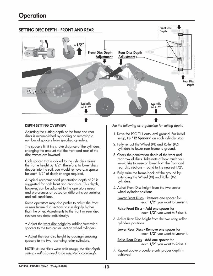
DEPTH SETTING OVERVIEW
Adjusting the cutting depth of the front and rear discs is accomplished by adding or removing a number of spacers from specified cylinders.
The spacers limit the stroke distance of the cylinders, changing the amount that the front and rear of the disc frames are lowered.
Each spacer that is added to the cylinders raises the frame height by 1/2”. Therefore, to lower discs deeper into the soil, you would remove one spacer for each 1/2” of depth change required.
A typical recommended penetration depth of 2” is suggested for both front and rear discs. This depth, however, can be adjusted to the operators needs and preferences or based on different crop varieties and soil conditions.
Some operators may also prefer to adjust the front or rear frame disc sections to run slightly higher than the other. Adjustments to the front or rear disc sections are done individually: • Adjust the front disc height by adding/removing spacers to the two center section wheel cylinders.
• Adjust the rear disc height by adding/removing spacers to the two rear wing roller cylinders.
NOTE: As the discs wear with usage, the disc depth settings will also need to be adjusted accordingly.
Use the following as a guideline for setting depth:
1. Drive the PRO-TILL onto level ground. For initial setup, try "12 Spacers" on each cylinder stop.
2. Fully retract the Wheel (#1) and Roller (#2) cylinders to lower rear frame to ground.
3. Check the penetration depth of the front and rear row of discs. Take note of how much you would like to raise or lower both the front and rear disc sections - round to the nearest 1/2”.
4. Fully raise the frame back off the ground by extending the Wheel (#1) and Roller (#2) cylinders.
5. Adjust Front Disc height from the two center wheel cylinder positions.
Lower Front Discs - Remove one spacer for each 1/2” you want to Lower it.
Raise Front Discs - Add one spacer for each 1/2” you want to Raise it.
6. Adjust Rear Disc height from the two wing roller cylinders positions.
Lower Rear Discs - Remove one spacer for each 1/2” you want to Lower it.
Raise Rear Discs - Add one spacer for each 1/2” you want to Raise it.
7. Repeat above procedure until proper depth is achieved.
SETTING DISC DEPTH - FRONT AND REAR
Typically Set to 2”
Typically Set to 2”
Front Disc Depth Adjustment
Rear Disc Depth Adjustment
Rear Disc Depth
Front Disc Depth

-11-143368 - PRO-TILL 33/40 (26-April-2018)
Hole for holding in maintenance position.
Operation
SETTING SCRAPER POSITION SCRAPER POSITION OVERVIEW
Change into Storage Position:
• Loosen & remove the 4 bolts (2 per arm). • Rotate section upward to new position.• Reinstall bolts and tighten in place.• Reverse procedure to put into working position.
Change into Maintenance Position (from engaged):
• Loosen the 4 bolts (2 per arm). • Rotate section upward until top hole is open.• Tighten bolts to secure and/or insert bolt or insert pin (user supplied) into top hole to secure in position.
Change into Engaged Position (from maintenance):• Loosen the 4 bolts (2 per arm).
• Rotate section down until scraper blades are set to proper distance from inner roller groove. (1/4" to 3/8" is the recommended distance)
• Tighten bolts to secure in position.
REVERSING SCRAPER BLADES
Double Sided Scraper BladesNote: When blades are being reversed, the complete section must be changed at the same time or adjustment will not work properly.
The scraper blades are designed to be reversible in order to provide extended wear. It is advised to reorder replacement blades soon after reversing to prevent possible downtime in the future.
Storage Position
Maintenance Position
Engaged Position
Gap Distance 1/4”-3/8”
Remove the 4 bolts to rotate
into or out of “Storage position”
then re-install.
Retighten main bolts or insert a bolt/pin here to
hold in raised position.
SCRAPER SIDE-TO-SIDE POSITIONING
Inspect that the scraper plates are as close to centered as possible in the roller groove & that no scrapers are touching the sides of the rubber roller. (Ideally there should be a 1/4" gap)
If adjustment is needed, loosen thescraper arm clamps and adjust position until there is proper clearance on all edges. You may need to slightlyadjust engagement distance if side-to-side is unsuccessful.
Loosen Clamps to Adjust Side to Side
Needs Adjustment
1/4" Gap Both Sides

-12-143368 - PRO-TILL 33/40 (26-April-2018)
Troubleshooting - Pro-Till 33/40
Not folding up for transport:- Ensure hydraulic coupler has not disengaged or try a
different tractor hydraulic port.
- Check for hose or fitting leaks.
- Tractor hydraulic system should have 2800 psi.
- Hydraulic fluid bypassing piston seals in one or both hydraulic cylinders. (Replace cylinder or re-build with new seals).
- Excessive mud built up on frame & rollers. Clear off frame raise discs all the way up & drive 12-14 mph on firm soil to clear rollers.
Restriction or blocking on right side:- Raise the deflector plate.
- Raise working depth of adjustable disc.
- Raise machine working depth.
- Reduce operating speed slightly.
- Extend right hand wheel adjustment to lift end of wing.
- Check condition & operation of disc hubs (make sure they turn freely).
- Wait for soil conditions to dry out more.
Rear discs or roller not engaging in very hard soil:- Adjust pitch so front discs are higher by adding two
depth stops or more to wheel cylinders only (It may be necessary to lower overall machine depth also).
- Momentarily take out of float & extend transport cylinders to simulate a rigid hitch (flat ground only).Re-engage float as soon as possible to avoid possible equipment damage.
Mud not clearing from rubber rollers:- Check scraper to roller distance & adjust if necessary
(scraper should be 1/4" to 3/8” from roller).
- Check scraper plate wear & adjust or replace asnecessary (replace all scrapers per row at the same time).
- Check scraper row adjustment for slippage & re-torque or replace hardware if necessary.
Roller plugged in wet conditions:- Retract transport cylinders to pass over pushed up
mound & smooth out when soil dries.
- Raise discs all the way up & drive 12-14 mph on firm soil to clear rollers.
- In certain wet soil conditions place scrapers in storage position to continue operating.
- If plugging persists wait for soil conditions to dry out even more.
Roller skidding in wet conditions:- Check scraper operation & settings.
- Raise machine working depth.
- Adjust pitch so rear discs are slightly higher & raise machine working depth.
- Momentarily take out of float & extend transport cylinders to simulate a rigid hitch (flat ground only). Re-engage float as soon as possible to avoid possible equipment damage.
- Wait for soil conditions to dry out more.
- Check condition & operation of bearings on both ends of the rollers.
Plugging disc rows in wet conditions:- Ensure roller is turning & scrapers are set properly.
- Raise machine working depth.
- Increase operating speed slightly.
- Adjust pitch so front discs are slightly higher (add one more depth stop plate to wheel cylinders).
- Fully extend wheel & roller depth cylinders & hold for 30 seconds to re-phase.
- Check condition & operation of disc hubs (make sure they turn freely).
- Wait for soil conditions to dry out more.
Leaving a ridge or a groove between rollers:- Adjust ridge wiper down slightly to remove ridge.
- Adjust ridge wiper up slightly to eliminate groove.

-13-143368 - PRO-TILL 33/40 (26-April-2018)
Troubleshooting - Pro-Till 33/40
Leaving a ridge or a groove between passes:- Adjust deflector up to reduce ridge.
- Adjust deflector down to fill groove.
- Set right rear adjustable disc lower if there is a ridge.
- Set right rear adjustable disc higher if there is a groove.
- Check that end disc size configuration matches factory suggested setup.
- Reduce implement width on guidance for slightly more overlap.
Subsoil leaving a groove every 10”:- Adjust pitch to level machine (disc rows are not set to
the same depth).
- Adjust pitch to lower rear disc row (front is prone to running deeper with floating hitch & firm soil conditions).
- Rear discs following in front disc groove (see troubleshooting for this below).
End of wing discs cutting deeper orshallower than center:- Fully extend wheel & roller depth cylinders & hold for
30 seconds to re-phase.
- Extend wheel adjustment to lift end of wing if cutting deeper.
- Retract wheel adjustment to lower end of wing if cutting shallower.
- Check for same number of depth control plates used on each side.
Hopping or leaving waves:- Change operating speed (best performance is
achieved over 10mph).
- Change field working angle (best finishing at 5 to 15 degrees off previously worked).
- Adjust working depth (deeper & run slower or shallower to run faster).
- Pre-work heavy trash or wet areas at a slower speed & at a different angle than final pass.
- Wait for soil conditions to dry out more.
Tracking to the left:- Add a depth stop to wheel cylinders to
adjust the pitch so the front disc is higher.
- Reduce implement width on guidance system for slightly more overlap.
- Adjust implement offset on guidance system to the right.
Tracking to the right:- Add a depth stop to roller cylinders to
adjust the pitch so the rear disc is higher.
- Reduce implement width on guidance system for slightly more overlap.
- Adjust implement offset on guidance system to the left.
Rear discs following in front disc cut or discs not doing a full cut:- Adjust tracking by changing implement pitch.
- Adjust entire front row in small increments either left or right to achieve full cut.
- Check disc wear & adjust gang spacing or replace discs as necessary (as discs wear move front row right).
- Check factory settings on disc row locations to verifygang clamp hardware is tight & clamps have not slipped.
- Adjust GPS to actual cutting width minus 6” overlap per side depending on working depth.
(with 20" discs) 2" Depth MAX DepthPro-Till 33 32’-6” (9.9m) 32’-8” (10m)Pro-Till 40 39’-2” (11.9m) 39’-5” (12m) Pro-Till 40 CT 40’-11” (12.4m) 41’-1” (12.5m)

-14-143368 - PRO-TILL 33/40 (26-April-2018)
1. Review the Operator’s Manual and all safety items before working with, maintaining or operating the PRO-TILL.
2. Stop the tractor engine, set park brake, remove ignition key and wait for all moving parts to stop before servicing, adjusting, repairing or unplugging.
3. Keep hands, feet, clothing and hair away from all moving and/or rotating parts.
4. Clear the area of bystanders, especially children, when carrying out any maintenance and repairs or making any adjustments.
5. Place safety stands or large blocks under the frame before removing tires or working beneath the machine.
6. Be careful when working around or maintaining a high-pressure hydraulic system. Wear proper eye and hand protection when searching for a high pressure hydraulic leak. Use a piece of wood or cardboard as a backstop when searching for a pin hole leak in a hose or a fitting.
7. Always relieve pressure before disconnecting or working on hydraulic system.
8. Never disconnect Pro-Till from tractor if rear sections of machine are partially raised. See warning below:
MAINTENANCE SAFETY
Service & Maintenance
WARNING/DANGER: Never disconnect Pro-Till from tractor if rear sections of machine are partially
raised. Negative Hitch Weight may result, the hitch pole may suddenly raise and the rear section would come crashing down. Only disconnect when unit is on level ground in the proper transport or field position.
MAINTENANCE CHECKLIST
(Note: Do NOT grease the spherical bearings)
Maintenance Check - 10 Hours
• Hydraulic fluid leaks
• Damaged hoses
• Check tire pressure:Outer Wing Tires (FL630 ULTRA): 600/50 R22.5: 58 PSI (400 kPa)
Center/Transport Tires (382 FLOTRUCK): 600/50 R22.5: 94 PSI (648 kPa)
Grease Points - 25 Hours
• Front Frame / Rockshaft Pins
• Wing Frame Pins
• Cylinder Pins
Grease Points - 50 Hours
• Wing Transport Roller Pins
• Hubs & Spindles
• Working points & pins
• Safety signs clean
Annually
• Bolt tightness
• Wheel bearings
After reviewing the Maintenance and Hydraulic Safety Information, use the Maintenance Checklist provided for regular service intervals and keep a record of all scheduled maintenance:
IMPORTANT: Safely securePro-Till in winged forward transport position when
changing or servicing discs.

-15-143368 - PRO-TILL 33/40 (26-April-2018)
Service & Maintenance
GREASING
Grease: Use an SAE multipurpose grease with extreme pressure (EP) performance. Also acceptable is an SAE multipurpose lithium.
1. Use only a hand-held grease gun for all greasing.
2. Wipe grease fitting with a clean cloth before greasing, to avoid injecting dirt.
3. Replace and repair broken fittings immediately.
4. If fittings will not take grease, remove and clean thoroughly. Also clean lubricant passageway. Replace fitting if necessary.
5. Inject grease until you see grease being expelled from the bearing or bushing areas.
SERVICE
Wheel Tightening Procedure
1. Install and hand tighten nuts/bolts.
2. Tighten to approx. 20% Torque value using the Bolt Star or CrissCross patterns shown above.
3. Tighten to Full Torque value using the Star or CrissCross pattern.
4. If applicable, install Rear Locknuts using Wheel Torque Values.
Wheel Nut/Bolt Torque Size lb.ft (N.m) 9/16 120-130 (165-175) 5/8 185-190 (250-260) 3/4 280-300 (380-405)
BOLT PATTERNS
2
1
6
5 3
4
6 BOLT PATTERN2
1
3 4
5 7
8
8 BOLT PATTERN
1
2
3 4
55 BOLT PATTERN
1
2
3
46
5
7 9
10 8
10 BOLT PATTERN
WHEEL NUT & WHEEL BOLT TORQUETORQUE
WHEEL HUB REPAIR
DISASSEMBLY
1. Remove dust cap.
2. Remove cotter pin from nut.
3. Remove nut and washer.
4. Pull hub off spindle.
5. Dislodge the inner cone bearing and dust seal.
6. Inspect cups that are press
fitted into hub for pits or corrosion and remove if necessary.
7. Inspect and replace defective parts with new ones.
ASSEMBLY
1. If cups need replacing, be careful to install them gently and evenly into hub until they are fully seated.
2. Apply a thick wall of grease inside hub. Pack grease in cones.
3. Install inner cone and dust seal as illustrated.
4. Position hub onto spindle and fill surrounding cavity with grease.
5. Assemble outer cone, washer and nut.
6. Tighten nut while rotating hub until there is a slight drag.
7. Turn nut back approximately 1/2 turn to align cotter pin hole with notches on nut.
8. Install cotter pin and bend legs sideways over nut.
9. Fill dust cap half full of grease and gently tap into position.
10. Pump grease into hub through grease fitting until lubricant can be seen from dust seal.
COMMON HUB & SPINDLE COMPONENTS
Dust Seal
Inner Cone
Inner Cup
Hub
Outer Cup
Outer Cone
Flat Washer
Slotted Nut & Cotter Pin
Dust Cap
Spindle
IMPORTANT: Be sure to block up unit securely
before removing tires.

-16-143368 - PRO-TILL 33/40 (26-April-2018)
Service & Maintenance
HYDRAULIC HOSE SPECIFICATIONS
Note: Unless otherwise stated, Hydraulic Hoses are either 3/8 or 1/2 with 3/4 JIC female swivel ends.
• Make sure that all components in the hydraulic system are kept in good condition and are clean.
• Replace any worn, cut, abraded, fl attened or crimped hoses and metal lines.
• Do not attempt any makeshift repairs to the hydraulic lines, fi ttings or hoses by using tape, clamps or cements. The hydraulic system operates under extremely high-pressure. Such repairs will fail suddenly and create a hazardous and unsafe condition.
• Wear proper hand and eye protection when searching for a high-pressure hydraulic leak. Use a piece of wood or cardboard as a backstop instead of hands to isolate and identify a leak.
• If injured by a concentrated high-pressure stream of hydraulic fl uid, seek medical attention immediately. Serious infection or toxic reaction can develop from hydraulic fl uid piercing the skin surface.
• Before applying pressure to the system, make sure all components are tight and that lines, hoses and couplings are not damaged.
HYDRAULIC SAFETY
IMPERIAL TORQUE SPECIFICATIONS(Coarse Thread - based on “Zinc Plated” values)
SAE-5 SAE-8
Size Grade 5 Grade 8 lb.ft (N.m) lb.ft (N.m) 1/4” 7 (10) 10 (14) 5/16” 15 (20) 20 (28) 3/8” 25 (35) 35 (50) 7/16” 40 (55) 60 (80) 1/2” 65 (90) 90 (120) 9/16” 90 (125) 130 (175) 5/8” 130 (175) 180 (245) 3/4” 230 (310) 320 (435) 7/8” 365 (495) 515 (700) 1” 550 (745) 770 (1050) 1-1/8” 675 (915) 1095 (1485) 1-1/4” 950 (1290) 1545 (2095) 1-3/8” 1250 (1695) 2025 (2745) 1-1/2” 1650 (2245) 2690 (3645)
METRIC TORQUE SPECIFICATIONS(Coarse Thread - based on “Zinc Plated” values)
8.8 10.9
Size Class 8.8 Class 10.9 lb.ft (N.m) lb.ft (N.m) M6 7 (10) 10 (14) M8 16 (22) 23 (31) M10 30 (42) 45 (60) M12 55 (75) 80 (108) M14 90 (120) 125 (170) M16 135 (185) 195 (265) M18 190 (255) 270 (365) M20 265 (360) 380 (515) M22 365 (495) 520 (705) M24 460 (625) 660 (895) M27 675 (915) 970 (1315) M30 915 (1240) 1310 (1780) M33 1250 (1695) 1785 (2420) M36 1600 (2175) 2290 (3110)
TORQUE SPECIFICATIONS
Checking Bolt TorqueThe tables below give correct torque values for various bolts and capscrews. Tighten all bolts to the torques specifi ed in chart unless otherwise noted. Check the tightness of bolts periodically, using these bolt torque charts as a guide. Replace hardware with the same strength (Grade/Class) bolt.
TORQUE
Note: Unless stated otherwise, hardware is typically: Hex, Plated GR5 UNC or P8.8 (metric)
HARDWARE SPECIFICATIONS
HYDRAULIC HOSE INSTALLATION TIPS
The following tips are to help you identify some possible problem areas in the installation of hydraulic hoses.
1. Ensure hoses are not twisted during installation as this may weaken the hose. Also, the pressure in a twisted hose may loosen fi ttings or connections.
2. Allow suffi cient bend radius in hoses when installing to prevent lines from collapsing and fl ow becoming restricted.
3. When installing hoses in an area of movement or fl exing, allow enough free length for motion and to ensure fi tting connections are not stressed.
4. Ensure hoses are properly clamped and secured in position after routing is complete to provide a cleaner installation and prevent possible damage or hazards.
v1.0
-17-143368 - PRO-TILL 33/40 (26-April-2018)
Service & Maintenance
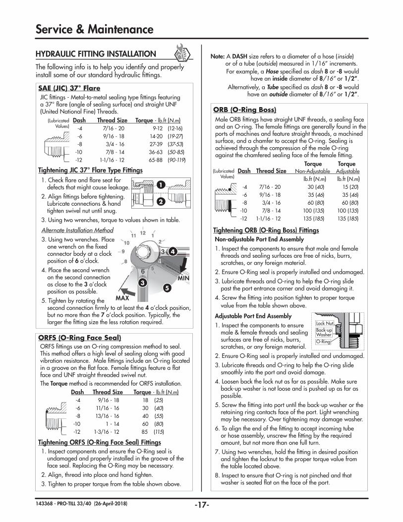
Note: A DASH size refers to a diameter of a hose (inside) or of a tube (outside) measured in 1/16” increments. For example, a Hose specifi ed as dash 8 or -8 would
have an inside diameter of 8/16” or 1/2”.Alternatively, a Tube specifi ed as dash 8 or -8 would
have an outside diameter of 8/16” or 1/2”.
The following info is to help you identify and properly install some of our standard hydraulic fi ttings.
HYDRAULIC FITTING INSTALLATION
SAE (JIC) 37° Flare JIC fi ttings - Metal-to-metal sealing type fi ttings featuring a 37° fl are (angle of sealing surface) and straight UNF (United National Fine) Threads.
Alternate Installation Method 3. Using two wrenches. Place
one wrench on the fi xed connector body at a clock position of 6 o’clock.
4. Place the second wrench on the second connection as close to the 3 o’clock position as possible.
5. Tighten by rotating the second connection fi rmly to at least the 4 o’clock position,
but no more than the 7 o’clock position. Typically, the larger the fi tting size the less rotation required.
MAX
MIN
4
53
Tightening JIC 37° Flare Type Fittings1. Check fl are and fl are seat for
defects that might cause leakage.2. Align fi ttings before tightening.
Lubricate connections & hand tighten swivel nut until snug.
3. Using two wrenches, torque to values shown in table.
1
2
Dash Thread Size Torque - lb.ft (N.m) -4 7/16 - 20 9-12 (12-16) -6 9/16 - 18 14-20 (19-27) -8 3/4 - 16 27-39 (37-53) -10 7/8 - 14 36-63 (50-85) -12 1-1/16 - 12 65-88 (90-119)
(Lubricated Values)
Male ORB fi ttings have straight UNF threads, a sealing face and an O-ring. The female fi ttings are generally found in the ports of machines and feature straight threads, a machined surface, and a chamfer to accept the O-ring. Sealing is achieved through the compression of the male O-ring against the chamfered sealing face of the female fi tting.
Non-adjustable Port End Assembly1. Inspect the components to ensure that male and female
threads and sealing surfaces are free of nicks, burrs, scratches, or any foreign material.
2. Ensure O-Ring seal is properly installed and undamaged.3. Lubricate threads and O-ring to help the O-ring slide
past the port entrance corner and avoid damaging it. 4. Screw the fi tting into position tighten to proper torque
value from the table shown above.
Adjustable Port End Assembly1. Inspect the components to ensure
male & female threads and sealing surfaces are free of nicks, burrs, scratches, or any foreign material.
2. Ensure O-Ring seal is properly installed and undamaged.3. Lubricate threads and O-ring to help the O-ring slide
smoothly into the port and avoid damage.4. Loosen back the lock nut as far as possible. Make sure
back-up washer is not loose and is pushed up as far as possible.
5. Screw the fi tting into port until the back-up washer or the retaining ring contacts face of the port. Light wrenching may be necessary. Over tightening may damage washer.
6. To align the end of the fi tting to accept incoming tube or hose assembly, unscrew the fi tting by the required amount, but not more than one full turn.
7. Using two wrenches, hold the fi tting in desired position and tighten the locknut to the proper torque value from the table located above.
8. Inspect to ensure that O-ring is not pinched and that washer is seated fl at on the face of the port.
Tightening ORB (O-Ring Boss) Fittings
ORB (O-Ring Boss)
O-Ring
Lock NutBack-upWasher
Torque Torque Dash Thread Size Non-Adjustable Adjustable lb.ft (N.m) lb.ft (N.m) -4 7/16 - 20 30 (40) 15 (20) -6 9/16 - 18 35 (46) 35 (46) -8 3/4 - 16 60 (80) 60 (80) -10 7/8 - 14 100 (135) 100 (135) -12 1-1/16 - 12 135 (185) 135 (185)
(Lubricated Values)
ORFS fi ttings use an O-ring compression method to seal. This method offers a high level of sealing along with good vibration resistance. Male fi ttings include an O-ring located in a groove on the fl at face. Female fi ttings feature a fl at face and UNF straight threaded swivel nut. The Torque method is recommended for ORFS installation.
1. Inspect components and ensure the O-Ring seal is undamaged and properly installed in the groove of the face seal. Replacing the O-Ring may be necessary.
2. Align, thread into place and hand tighten.3. Tighten to proper torque from the table shown above.
Tightening ORFS (O-Ring Face Seal) Fittings
ORFS (O-Ring Face Seal)
Dash Thread Size Torque - lb.ft (N.m) -4 9/16 - 18 18 (25) -6 11/16 - 16 30 (40) -8 13/16 - 16 40 (55) -10 1 - 14 60 (80) -12 1-3/16 - 12 85 (115)

-18-143368 - PRO-TILL 33/40 (26-April-2018)
5
HYDRAULIC CYLINDER REPAIR
c) Use a screwdriver or a fi nger to hold one end of the ring in the groove while fi tting the other end of the ring into the groove. The tips should snap in together. Ensure it is secure and fully seated before the next step.
IMPORTANT: It is important to ensure the removal ring is completely in the groove before pulling the rod out. If the ring sticks out it will get stuck between the head and tube.
Note: Excessive force will not overcome a jammed ring and could damage the cylinder.
b) Completely remove rod and head from tube.
6. a) Extend the rod to pull head out of tube. If the rod does not pull out easily, push the head back in and ensure the ring is properly in the groove. Replace ring if necessary.
7
7. Remove plastic removal ring from the cylinder tube.
6
Plastic Ring
Inner Wire Ring
5. Take the plastic removal ring from the seal kit: a) Straighten the ring and remove any kinks or
excessive curl to make installation easier and prevent it from falling out.
b) Insert the removal ring into the internal groove with the feathered
end pointing into the tube.
1. Retract the rod assembly.
2. Remove the external steel wire ring.
REPAIRING A WIRE RING CYLINDER
3. Remove any dirt that may have accumulated on the cylinder head.
4. Using the mallet and punch, push the head into the cylinder tube until the
internal tube groove is fully exposed. This will also move the internal wire ring into its removal position.
4
2
External RingInner Ring
Initial Ring Positions
4
Internal Groove
Inner RingOuter
Wire Ring(Removed)
v1.0
Set Screw
Wire Ring
Threaded Head
Types of Cylinders (Wire Ring / Threaded Head)
PREPARATION
When cylinder repair is required, clean off unit, disconnect hoses and plug ports before removing cylinder.
When removed, open the cylinder ports and drain the cylinder's hydraulic fl uid.
Examine the type of cylinder. Make sure you have the correct tools for the job.
You may require the following tools: • Proper Seal Kit• Rubber Mallet• Screwdriver • Punch• Pliers• Emery cloth• Torque Wrench
Service & Maintenance

-19-143368 - PRO-TILL 33/40 (26-April-2018)
11. b) Tighten the band clamp to ensure the wire ring is fully seated. Then, loosen the clamp approx. 1/2 a turn to allow band clamp to slide during fi nal assembly.
17b) Pull out Head for
Wire Ring Groove
a) Extend RodForward
c) Install External Wire Ring
9. a) Inspect and replace all of the seals with new components.
b) Inspect the inside of the cylinder barrel, piston, rod and other polished parts for burrs and scratches. Smooth areas as needed with an emery cloth.
c) During re-assembly of head/gland assembly, leave the outer O-Ring Dual Seal loose on the rod to re-install at a later step.
10. Replace piston and torque the locknut to required value. (Refer to chart below)
11. a) Install the supplied band clamp to compress the inner wire ring on the head/gland assembly so it will fi t into the tube.
Note: Make sure the cam of the band clamp is not overtop of the gap in the ring.
12. Lubricate the cylinder tube and piston seals.
13. Insert the piston into the tube. Tap the cylinder head into the tube until the clamp slides over and the inner wire ring is inside the tube.
16
Flush with edge
16. Tap the head the rest of the way until the end is fl ush with the tube.
IMPORTANT: The head/gland must be inserted until it is fl ush with the tube to allow the inner wire ring to snap into its seated position in the internal cylinder groove. Failure to insert the head fl ush as shown will result in the head and rod assembly coming out of the tube when pressure is applied to the cylinder.
17. Pull the rod out to expose the external wire ring groove in cylinder head, and then install the external ring.
18. Before using the cylinder, ensure that you double check your work.
14. Loosen the clamp and remove.
15. Install the O-Ring Dual seal.
13
14
15
External RingInner Ring
LOCKNUT SIZE (PISTON) TORQUE VALUE 3/8 - 24 UNF 25-30 lb.ft (35-42 N.m) 1/2 - 20 UNF 40-60 lb.ft (55-80 N.m) 5/8 - 18 UNF 95-105 lb.ft (130-140 N.m) 3/4 - 16 UNF 175-225 lb.ft (240-305 N.m) 7/8 - 14 UNF 200-275 lb.ft (270-370 N.m) 1 - 14 UNF 300-380 lb.ft (405-515 N.m)1 1/8 - 12 UNF 400-500 lb.ft (540-675 N.m)1 1/4 - 12 UNF 500-600 lb.ft (675-810 N.m)1 1/2 - 12 UNF 700-800 lb.ft (950-1085 N.m)1 3/4 - 12 UNF 800-900 lb.ft (1085-1220 N.m)
16
Inner Wire Ring is pushed back into the internal
Tube Groove
8. Remove locknut, piston and head from rod.
Wiper Seal
Wear RingWear Ring
Locknut
Piston
Head/Gland
U-Cup Rod Seal
Piston Seal (2pcs)
O-RingDual Seal
O.D. Threads = Locknut Size
Service & Maintenance
-20-143368 - PRO-TILL 33/40 (26-April-2018)
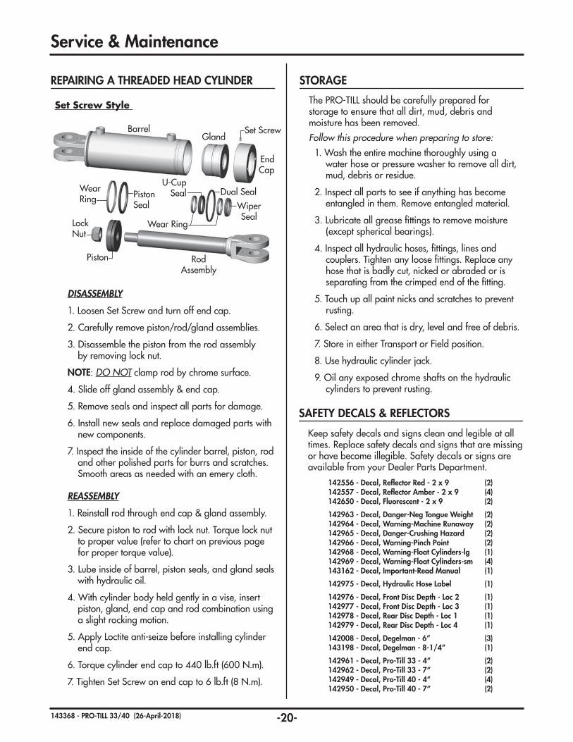
REPAIRING A THREADED HEAD CYLINDER
Barrel
RodAssembly
Lock Nut
Gland
End Cap
Set Screw
Piston Seal
Dual Seal
Wiper Seal
U-Cup SealWear
Ring
Wear Ring
Piston
DISASSEMBLY
1. Loosen Set Screw and turn off end cap.
2. Carefully remove piston/rod/gland assemblies.
3. Disassemble the piston from the rod assembly by removing lock nut.
NOTE: DO NOT clamp rod by chrome surface.
4. Slide off gland assembly & end cap.
5. Remove seals and inspect all parts for damage.
6. Install new seals and replace damaged parts with new components.
7. Inspect the inside of the cylinder barrel, piston, rod and other polished parts for burrs and scratches. Smooth areas as needed with an emery cloth.
REASSEMBLY
1. Reinstall rod through end cap & gland assembly.
2. Secure piston to rod with lock nut. Torque lock nut to proper value (refer to chart on previous page for proper torque value).
3. Lube inside of barrel, piston seals, and gland seals with hydraulic oil.
4. With cylinder body held gently in a vise, insert piston, gland, end cap and rod combination using a slight rocking motion.
5. Apply Loctite anti-seize before installing cylinder end cap.
6. Torque cylinder end cap to 440 lb.ft (600 N.m).
7. Tighten Set Screw on end cap to 6 lb.ft (8 N.m).
Set Screw Style
Service & Maintenance
Keep safety decals and signs clean and legible at all times. Replace safety decals and signs that are missing or have become illegible. Safety decals or signs are available from your Dealer Parts Department.
SAFETY DECALS & REFLECTORS
142556 - Decal, Reflector Red - 2 x 9 (2)142557 - Decal, Reflector Amber - 2 x 9 (4)142650 - Decal, Fluorescent - 2 x 9 (2)
142963 - Decal, Danger-Neg Tongue Weight (2) 142964 - Decal, Warning-Machine Runaway (2)142965 - Decal, Danger-Crushing Hazard (2)142966 - Decal, Warning-Pinch Point (2)142968 - Decal, Warning-Float Cylinders-lg (1)142969 - Decal, Warning-Float Cylinders-sm (4)143162 - Decal, Important-Read Manual (1)
142975 - Decal, Hydraulic Hose Label (1)
142976 - Decal, Front Disc Depth - Loc 2 (1)142977 - Decal, Front Disc Depth - Loc 3 (1)142978 - Decal, Rear Disc Depth - Loc 1 (1)142979 - Decal, Rear Disc Depth - Loc 4 (1)
142008 - Decal, Degelman - 6” (3)143198 - Decal, Degelman - 8-1/4” (1)
142961 - Decal, Pro-Till 33 - 4” (2)142962 - Decal, Pro-Till 33 - 7” (2)142949 - Decal, Pro-Till 40 - 4” (4)142950 - Decal, Pro-Till 40 - 7” (2)
The PRO-TILL should be carefully prepared for storage to ensure that all dirt, mud, debris and moisture has been removed.
Follow this procedure when preparing to store:1. Wash the entire machine thoroughly using a
water hose or pressure washer to remove all dirt, mud, debris or residue.
2. Inspect all parts to see if anything has become entangled in them. Remove entangled material.
3. Lubricate all grease fittings to remove moisture (except spherical bearings).
4. Inspect all hydraulic hoses, fittings, lines and couplers. Tighten any loose fittings. Replace any hose that is badly cut, nicked or abraded or is separating from the crimped end of the fitting.
5. Touch up all paint nicks and scratches to prevent rusting.
6. Select an area that is dry, level and free of debris.
7. Store in either Transport or Field position.
8. Use hydraulic cylinder jack.
9. Oil any exposed chrome shafts on the hydraulic cylinders to prevent rusting.
STORAGE

-21-143368 - PRO-TILL 33/40 (26-April-2018)
Pro-Till Overview
Front Hitch
Hyd Jack Assembly
Center Frame
Hitch Pole Frame
Hitch Pole Legs
CenterRoller Frame
Wing Roller Frame
LH Wing Disc Gangs
RH Wing Disc Gangs
CenterDisc Gangs
LH Wing Frame
LH Wheel Strut
Wheel Rockshaft
RH Wheel Strut
RH Wing Frame
Cage Roller
Cage Roller
Cage Roller
Rubber Roller
Rubber Roller
Rubber Roller
Scraper
- or -
- or -
- or -Scraper
Scraper
Wing Roller Frame
Exploded Overview of a Pro-Till 40

-22-143368 - PRO-TILL 33/40 (26-April-2018)
572870 - Hitch Pole Frame Assembly (1)
572722 - Transport Wing Carrier Assembly (2)
780278 - Hose Clamp - 2 Halves (11)
780279 - Top Plate (11)
118144 - Bolt, 5/16 x 1-1/2 (11)
x2
x2
x2
118775 - Flat washer, 3/4 F436 (16)117414 - Lock Nut, 3/4 - Unitorque (8)
117145 - Bushing (2)
118050 - Bolt, 3/4 x 3 (8) - 40’ Pro-Till
142008 - Decal, Degelman - 6” (2)
143198 - Decal, Degelman - 8-1/4” (1)
572915 - Pin, 1-15/16 x 10-1/4 (2)mounts with...
142135 - SMV Sign (1) mounts with...
118772 - Lock Washer, 3/4 GR8 (2)118635 - Flat Washer, 3/4 x 2-1/4 (2)
118040 - Bolt, 3/4 x 1-1/2 (2)
118483 - Lock Nut, 1/4 - Unitorque (2)118123 - Bolt, 1/4 x 1 (2)
Transport Cylinder 123048 (2)
Hitch Pole Legs
Jack / Hydraulic Mount Frame
Front Hitch
Front FrameTransport
Wing Carrier
Hitch Pole / Front Frame Components
Hitch Pole/Front Frame Overview
Front Frame Components
572780 - Spacer (4)(33’ Pro-Till only)
(Same on Opposite Side)
142969 - Decal, Float Cylinder (2)
1”
142557 - Decal, Reflector Amber
- 2 x 9 (2) (See electrical wire routing page for light components)(33' Location
Shown)
Transport Wing Carrier Position
Pro-Till 33’
Transport Wing Carrier Position
Pro-Till 40’
Spacers RequiredDecal Location
Decal Location
Transport Wing CarrierTransport Wing Carrier
118119 - Bolt, 3/4 x 4 (8) - 33’ Pro-Till

-23-143368 - PRO-TILL 33/40 (26-April-2018)
Hitch Pole Frame Components
118483 - Lock Nut, 1/4 - Unitorque (4)118541 - Flat Washer, 1/4 (8)117586 - Bolt, 1/4 x 1-1/2 (4)
133100 - Manual Holder (1)mounts with...
Jack/Hydraulic Mount Frame Detail
572810 - Jack Base Assembly (1)
572805 - Jack Leg Assembly (1)
572927 - Hyd Hose Retainer Handle (1)comes with...572930 - Handle Grip
572815 - Pin, 1-1/4 x 7-3/4 (1)
572816 - Pin, 1-1/4 x 5-5/8 (1)
572817 - Pin, 1-1/2 x 7-3/4 (2)
117442 - Bush, Mach - 1-1/4 (2)
117442 - Bush, Mach - 1-1/4 (2)
240286 - Bush, Mach - 1-1/2 (4)
810280 - Retaining Ring, 1-1/4 (2)
810278 - Retaining Ring, 1-1/2 (4)
810280 - Retaining Ring, 1-1/4 (2)
118537 - Flat washer,5/8 - F436 (26)
118935 - Bolt, 5/8 x 2-1/2 GR8 (13)
118447 - Lock Nut, 5/8 Unitorque (13)
Jack Cylinder - 123420 (1)
780278 - Hose Clamp - 2 Halves (4)
780279 - Top Plate (4)
118144 - Bolt, 5/16 x 1-1/2 (4)
x4
142975 - Decal, Hose Location (1)
572931 - Ball, Pull PinNOTE: Add Blue Loctite
to threads
Hitch Pole Components
142654 - Decal, Patented (1)
2-1/8”
3/4”
3/4”
2”ABCD
3/8”
142963 - Decal, Danger - Negative (2)142965 - Decal, Danger - Crushing (2)142964 - Decal, Warning - Hazard (2)142966 - Decal, Warning - Pinch (2)
ABCD
141597 - Ball Valve - 3/4 ORB (1)
143162 - Decal, Read Manual (1)
573422 - Jack / Hydraulic Mount Frame Assembly (1)
572920 - Jack / Hydraulic
Mount Frame Assembly (1)
Previous Assembly: Prior to SN:1896
Available for Purchase572635 - Adapter
Plate, Pin 2" (1)
(Previous: 123055)
Previous Assembly: Prior to SN: 1896 - 572575 - Pole Leg Assembly - RH (1)
572582 - Pole Leg Assembly - RH (1)
572583 - Pole Leg Assembly - LH (1)Previous Assembly: Prior to SN: 1896 572576 - Pole Leg Assembly - LH (1)
780278 - Hose Clamp - 2 Halves (20)
780279 - Top Plate (20)
118144 - Bolt, 5/16 x 1-1/2 (20)
x2
118911 - Lock Nut, 1 (28)
131020 - Flat washer, 1 F436 (16)
572570 - Front Hitch Plate (1)
118911 - Lock Nut, 1 (8)
118911 - Lock Nut, 1 (8)
117565 - Bolt, 1 x 4-1/2 UNC GR8 (8)
116302 - Safety Chain Assembly (1)
142962 - Decal, Pro-Till 33 - 7” (2)(142950 - Decal, Pro-Till 40 - 7”)
117565 - Bolt, 1 x 4-1/2 UNC
GR8 (28) 131020 - Flat washer, 1 F436 (56)
(Previous)
27"19"
Previous Safety Chain Mounting Components:
131020 - Flat washer, 1 F436 (1)
118911 - Lock Nut, 1 (1)
118376 - Bolt, 1 x 6 UNC GR8 (1)118615 - Flat washer, 1 x 3-1/8 (1)
117565 - Bolt, 1 x 4-1/2 UNC GR8 (1)
131020 - Flat washer, 1 F436 (2)
572614 - Spacer (1)
572578 - Optional Hitch Assembly (1)
118911 - Lock Nut, 1 (3)
117429 - Bolt, 1 x 7-1/2
UNC GR8 (3)
124041 - Bushing, CAT 5, for 2" Pin (1)
572573 - Hitch Mount
CAT 5 (1)
124043 - Ball Hitch, CAT 5 -
2-3/4" (1)
131020 - Flat washer, 1 F436 (6)
-24-143368 - PRO-TILL 33/40 (26-April-2018)
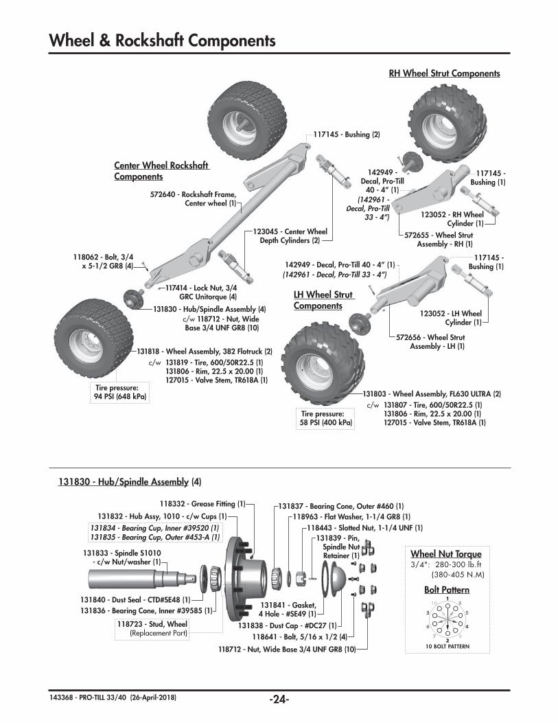
RH Wheel Strut Components
Wheel & Rockshaft Components
131830 - Hub/Spindle Assembly (4)
123052 - RH Wheel Cylinder (1)
572655 - Wheel Strut Assembly - RH (1)
117145 - Bushing (1)
142949 - Decal, Pro-Till
40 - 4” (1)(142961 -
Decal, Pro-Till 33 - 4”)
Center Wheel Rockshaft Components
117145 - Bushing (2)
123045 - Center Wheel Depth Cylinders (2)
572640 - Rockshaft Frame, Center wheel (1)
131830 - Hub/Spindle Assembly (4)
131818 - Wheel Assembly, 382 Flotruck (2)
c/w 118712 - Nut, Wide Base 3/4 UNF GR8 (10)
c/w 131819 - Tire, 600/50R22.5 (1) 131806 - Rim, 22.5 x 20.00 (1) 127015 - Valve Stem, TR618A (1)
118062 - Bolt, 3/4 x 5-1/2 GR8 (4)
117414 - Lock Nut, 3/4 GRC Unitorque (4)
118641 - Bolt, 5/16 x 1/2 (4)
118712 - Nut, Wide Base 3/4 UNF GR8 (10)
131840 - Dust Seal - CTD#SE48 (1)
131833 - Spindle S1010 - c/w Nut/washer (1)
131837 - Bearing Cone, Outer #460 (1)
131835 - Bearing Cup, Outer #453-A (1)118443 - Slotted Nut, 1-1/4 UNF (1)
118963 - Flat Washer, 1-1/4 GR8 (1)
131839 - Pin, Spindle Nut Retainer (1)
131832 - Hub Assy, 1010 - c/w Cups (1)
118332 - Grease Fitting (1)
131836 - Bearing Cone, Inner #39585 (1)
131834 - Bearing Cup, Inner #39520 (1)
131841 - Gasket, 4 Hole - #SE49 (1)
131838 - Dust Cap - #DC27 (1)
Bolt Pattern1
2
3
46
5
7 9
10 8
10 BOLT PATTERN
Wheel Nut Torque3/4": 280-300 lb.ft (380-405 N.M)
LH Wheel Strut Components
572656 - Wheel Strut Assembly - LH (1)
123052 - LH Wheel Cylinder (1)
117145 - Bushing (1)142949 - Decal, Pro-Till 40 - 4” (1)
(142961 - Decal, Pro-Till 33 - 4”)
Tire pressure: 58 PSI (400 kPa)
131803 - Wheel Assembly, FL630 ULTRA (2)c/w 131807 - Tire, 600/50R22.5 (1) 131806 - Rim, 22.5 x 20.00 (1) 127015 - Valve Stem, TR618A (1)
Tire pressure: 94 PSI (648 kPa)
118723 - Stud, Wheel (Replacement Part)

-25-143368 - PRO-TILL 33/40 (26-April-2018)
Center Frame & Center Roller Frame Components
Cast Bearing Assembly (6)
Center Frame Components
141524 - Relief Valve, 2000 PSI - 3/4 ORB (1)
131855 - Rubber Roller Assembly, LSTX 4m (1)
4m Scraper Assembly, Bolted
572450 - Cage Roller Assembly (1)
-OR-
117145 - Bushing (2)
Center Roller Cylinder 123052 (2)
Center Roller Frame
(Previous: See electrical wire routing pages for light components)
Previous: 142556 - Decal, Reflector Red - 2 x 9 (2)
118165 - Bolt, 1 x 12 - GR8 (2)
117585 - Bushing, Devol (1)
118911 - Lock Nut, 1 UNC (2)
110062 - Shim, 16 Ga. (2)110061 - Bearing Base (2)
Same Top & Bottom
Cast Bearing Assembly Components - 1"
IMPORTANT: Torque to 550 lb.ft (750 N.m)
MarkingType A Type B Marking
Marking Marking
IMPORTANT: When installing, position castings halves so matching markings are located on the same side only. Do not mis-match.
131020 - Flat Washer, 1 F436 (4)
AA
AA
A
A
A
A
AAA
AA
AA
B
B
B
B
B
780278 - HoseClamp,
2 Halves (25)
780279 - Top Plate (20)
118144 - Bolt, 5/16 x 1-1/2 (15)
118105 - Bolt, 5/16 x 2-1/2 (5)
A B
117579 - Bolt, Carriage 5/8 x 2-1/2 GR8 (8)
118447 - Lock Nut, 5/8 Unitorque (8)
572428 - Washer Endplate, 2 Hole (2)
572786 - Spacer, Bushing (2)
117171 - Bearing Unit, 4 Hole (2)117172 - Bearing Insert, 2-7/16 (1)
118186 - Bolt, 1/2 x 1-1/4 GR8 (4)
IMPORTANT:Add Blue Loctite to threads. Torque to: 80 lb.ft (108 N.m)
IMPORTANT: Setscrew MAX Torque is 30 lb.ft (41 N.m). Do not over-torque.
117145 - Bushing (8)
(See electrical wire routing page for light components)
(See electrical wire routing page for light
components)
572875 - Center Frame Assembly (1)
142008 - Decal, Degelman 6” (1)
572790 - Center Roller Frame (1)

-26-143368 - PRO-TILL 33/40 (26-April-2018)
142557Decal, Reflector
Amber - 2 x 9 (1)
118027 - Bolt, 5/8 x 2 GR8 (1)
572734 - Pin, 2 x 6-3/8 (1)
572660 - Wheel Adjusting Rod (1)
572915 - Pin, 1-15/16 x 10-1/4 (2)118772 - Lock Washer, 3/4 GR8 (2)
118040 - Bolt, 3/4 x 1-1/2 (2)
118635 - Flat washer, 3/4 x 2-1/4 (2)
572720 - Roller Bushing (1)
118447 - Lock Nut, 5/8 - Unitorque (1)
118451 - Jam Nut, 1-1/2 GR2 (2)117145 - Bushing (3)
572883 - Wing Frame Assembly - LH (shown) (1)
572882 - Wing FrameAssembly - RH (opposite) (1)
Wing Frame Components(LH Shown)
123050 -Wing Cylinder (1)
Cast Bearing Assembly (4) (Component parts & breakdown
shown on page 25) A A
780278 - HoseClamp,
2 Halves (7)
780279 - Top Plate (6)
118144 - Bolt, 5/16 x 1-1/2 (5)
118105 - Bolt, 5/16 x 2-1/2 (1)
A B
Wing Frame Components Pro-Till 33 (10m)
-OR-
Wing Roller Frame Pro-Till 33(LH Shown)
572793 - Roller Frame Assembly, LH Wing (shown) (1)
572792 - Roller Frame Assembly, RH Wing (opposite) (1)
117145 - Bushing (1)
131845 - Rubber Roller Assembly, LSTX 3m (1)
3m Scraper Assembly, Bolted
572440 - Cage Roller Assembly - 3m (1)
142969 - Decal, Float Cylinder (2)
(Same on Opposite Side)
1”
123045 - Wing Roller Depth Cylinder (1)
A
A A
B
117579 - Bolt, Carriage 5/8 x 2-1/2 GR8 (8)
118447 - Lock Nut, 5/8 Unitorque (8)
572428 - Washer Endplate, 2 Hole (2)
572786 - Spacer, Bushing (2)
117171 - Bearing Unit, 4 Hole (2)117172 - Bearing Insert, 2-7/16 (1)
118186 - Bolt, 1/2 x 1-1/4 GR8 (4)
IMPORTANT:Add Blue Loctite to threads. Torque to: 80 lb.ft (108 N.m)
IMPORTANT: Setscrew MAX Torque is 30 lb.ft (41 N.m). Do not over-torque.

-27-143368 - PRO-TILL 33/40 (26-April-2018)
Wing Frame Components Pro-Till 40 (12m)
-OR-
Wing Roller Frame Pro-Till 40(RH / LH)
(Decal Located LH on LH Wing, RH on RH Wing)
572791 - Roller Frame Assembly, Wing (1)
117145 - Bushing (1)
142949 - Decal, Pro-Till - 4” (1)
131855 - Rubber Roller Assembly, LSTX 4m (1)
4m Scraper Assembly, Bolted
572450 - Cage Roller Assembly - 4m (1)
118027 - Bolt, 5/8 x 2 GR8 (1)
572734 - Pin, 2 x 6-3/8 (1)
572660 - Wheel Adjusting Rod (1)
572720 - Roller Bushing (1)118447 - Lock Nut, 5/8
- Unitorque (1)
118451 - Jam Nut, 1-1/2 GR2 (2)
117145 - Bushing (2)
117145 - Bushing (1)
Wing Frame Components(LH Shown)
572881 - Wing Frame Assembly - LH (shown) (1)
572880 - Wing FrameAssembly - RH (opposite) (1)
142557 - Decal, Reflector Amber - 2 x 9 (1)
142969 - Decal, Float Cylinder (2)
(Same on Opposite Side)
1”
572915 - Pin, 1-15/16 x 10-1/4 (2)
118772 - Lock Washer, 3/4 GR8 (2)118040 - Bolt, 3/4 x 1-1/2 (2)
118635 - Flat washer, 3/4 x 2-1/4 (2)
117579 - Bolt, Carriage 5/8 x 2-1/2 GR8 (8)
118447 - Lock Nut, 5/8 Unitorque (8)
572428 - Washer Endplate, 2 Hole (2)
572786 - Spacer, Bushing (2)
117171 - Bearing Unit, 4 Hole (2)117172 - Bearing Insert, 2-7/16 (1)
Cast Bearing Assembly (5) (Component parts & breakdown
shown on page 25)
780278 - HoseClamp,
2 Halves (7)
780279 - Top Plate (6)
118144 - Bolt, 5/16 x 1-1/2 (5)
118105 - Bolt, 5/16 x 2-1/2 (1)
A B
A
A A
A
A
B
118186 - Bolt, 1/2 x 1-1/4 GR8 (4)
IMPORTANT:Add Blue Loctite to threads. Torque to: 80 lb.ft (108 N.m)
IMPORTANT: Setscrew MAX Torque is 30 lb.ft (41 N.m). Do not over-torque.
123045 - Wing Roller Depth Cylinder (1)
123050 -Wing Cylinder (1)

-28-143368 - PRO-TILL 33/40 (26-April-2018)
Wing Frame Components Pro-Till 40 Controlled Traffic (12.5m)
-OR-
(Decal Located LH on LH Wing, RH on RH Wing)
572967 - Roller Frame Assembly, Wing-LH (1)572968 - Roller Frame Assembly, Wing-RH (1)
117145 - Bushing (1)
142949 - Decal, Pro-Till - 4” (1)
131865 - Rubber Roller Assembly, LSTX 4.2m (1)
4.2m Scraper Assembly, Bolted
572460 - Cage Roller Assembly - 4.2m (1)
118027 - Bolt, 5/8 x 2 GR8 (1)
572734 - Pin, 2 x 6-3/8 (1)
572660 - Wheel Adjusting Rod (1)
572720 - Roller Bushing (1)118447 - Lock Nut, 5/8
- Unitorque (1)
118451 - Jam Nut, 1-1/2 GR2 (2)
117145 - Bushing (2)
117145 - Bushing (1)
Wing Frame Components(LH Shown)
572881 - Wing Frame Assembly - LH (shown) (1)
572880 - Wing FrameAssembly - RH (opposite) (1)
142557 - Decal, Reflector Amber - 2 x 9 (1)
142969 - Decal, Float Cylinder (2)
(Same on Opposite Side)
1”
572915 - Pin, 1-15/16 x 10-1/4 (2)
118772 - Lock Washer, 3/4 GR8 (2)118040 - Bolt, 3/4 x 1-1/2 (2)
118635 - Flat washer, 3/4 x 2-1/4 (2)
117579 - Bolt, Carriage 5/8 x 2-1/2 GR8 (8)
118447 - Lock Nut, 5/8 Unitorque (8)
572428 - Washer Endplate, 2 Hole (2)
572786 - Spacer, Bushing (2)
117171 - Bearing Unit, 4 Hole (2)117172 - Bearing Insert, 2-7/16 (1)
Cast Bearing Assembly (5) (Component parts & breakdown
shown on page 25)
780278 - HoseClamp,
2 Halves (7)
780279 - Top Plate (6)
118144 - Bolt, 5/16 x 1-1/2 (5)
118105 - Bolt, 5/16 x 2-1/2 (1)
A B
A
A A
A
A
B
118186 - Bolt, 1/2 x 1-1/4 GR8 (4)
IMPORTANT:Add Blue Loctite to threads. Torque to: 80 lb.ft (108 N.m)
IMPORTANT: Setscrew MAX Torque is 30 lb.ft (41 N.m). Do not over-torque.
123045 - Wing Roller Depth Cylinder (1)
123050 -Wing Cylinder (1)
Wing Roller Frame Pro-Till 40 Controlled Traffic(RH / LH)

-29-143368 - PRO-TILL 33/40 (26-April-2018)
Roller Assembly Overview
Rubber Roller Components
131712 - End Plate (2)
131716 - Axle Key (2)
131722 - Axle Lock Nut (2)
117572 - Bolt, M14 x 50 - 10.9 (12)
131725 - Washer, Roller End Plate (12)
131717 - End Axle Shaft (2)
131723 - Axle Lock Washer (2)
Roller End Rubber
Common Roller End Assembly Components
Ridge Wiper Components Knocks down the possible ridge of dirt left from buildup in between the rollers. 573385 - Ridge Wiper Kit (1)
- 2 Kits Required per machine
2nd Installed on LH end of RH Roller1st Installed on LH end of Center Roller
Initially set to highest setting as shown then adjust lower as necessary until desired results are achieved. Note: Setting too low can result in a trench or possibly cause plugging.
118221 - Bolt, CRG 5/8 x 2 (2)117581 - TopLock Nut, 5/8 Flanged (2)
118447 - Lock Nut, 5/8 Unitorque (2)117460 - Bolt, CRG 5/8 x 3 GR8 (2)
573386 - Ridge Wiper Mount (1)
573387 - Ridge Wiper (1)
131845 - Roller Assembly, LSTX 3m (1)
131855 - Roller Assembly, LSTX
4m (1)
131865 - Roller Assembly, LSTX
4.2m (1) 131846 - End Rubber Ring LSTX (2)
LSTX Roller
131848 - Middle Rubber Ring LSTX (2)
131847 - Standard Rubber Ring LSTX(3m-20, 4m-28, 4.2m-30)
131816 - Tube Assembly - 4m (1)131730 - Tube Assembly - 3m (1)
131866 - Tube Assembly - 4.2m (1)
4m
4m
3m
4m
3m
4m
4m4.2m 4.2m
ProTill 40ProTill 33
ProTill 40Controlled Traffic

-30-143368 - PRO-TILL 33/40 (26-April-2018)
Max-Life Replacement Scraper Blades requires new hardware (Locknuts)
572957 - Scraper Blade, Max-Life - 1/4
118186 - Bolt, 1/2 x 1-1/4 GR8118729 - Lock Nut, 1/2 Unitorque
Wear Edge down
Heavy Duty Replacement Scraper Blades requires new hardware (Bolts & Locknuts)Note: Replacement part only. Works best only after roller has been run and has relaxed into its permanent shape.
573320 - Scraper Blade, HD - 3/8118279 - Bolt, 1/2 x 1-1/2 GR8118729 - Lock Nut, 1/2 Unitorque
Must purchase by QTY: ProTill 33': 77 ProTill 40': 93 or ProTill 40' CT: 97
Standard - Scraper Blade Kits - c/w Bolts & Locknuts.
33' Kit: 572675 (Set of 77) 40' Kit: 572750 (Set of 93)
Scraper Blade Replacement
Options
Scraper Section Component Overview
572962 - Frame Mounting Arm (2)
572938 - Scraper Mounting Arm, Threaded (3m-23, 4m-31, 4.2m-33)
117599 - Lock Washer, 1/2 Nordlock (3m-23, 4m-31, 4.2m-33)
572891 - V-Clamp, Plate (2)
117486 - Bolt, 3/4 x 2-3/4 GR8 (4)
118186 - Bolt, 1/2 x 1-1/4 GR8 (3m-23, 4m-31, 4.2m-33)
118134 - Bolt, 1 x 3 GR8 (4)
118775 - Flat Washer, 3/4 F436 (8)
131020 - Flat Washer, 1 F436 (8)
117414 - Lock Nut, 3/4 Unitorque (4)
118729 - Lock Nut, 1/2 Unitorque (3m-23, 4m-31, 4.2m-33)
118911 - Lock Nut, 1 GRC (4)
572933 - 4m Scraper Mount Assembly (1) 572936 - 3m Scraper Mount Assembly (1)
118186 - Bolt, 1/2 x 1-1/4 GR8 (3m-23, 4m-31, 4.2m-33)
110067 - Washer, Scraper - Cast (3m-23, 4m-31, 4.2m-33)
572955 - Scraper Blade, Standard 1/4 (3m-23, 4m-31, 4.2m-33)
IMPORTANT: Add Loctite to threads & Torque to 66 lb.ft (90 N.m)
Scraper Position Overview
Gap Distance 1/4” to 3/8”
from roller surface.
Storage Position
Maintenance Position
Engaged Position
Remove the 4 bolts to rotate intoor out of “Storage position”,then re-install.
Loosen the 4 bolts to rotate up into “Maintenance
Position” & secure.
Loosen the 4 bolts to rotate. Set the Scraper-to-Roller
Gap distance between 1/4" to 3/8” then
properly tighten.
572973 - 4.2m Scraper Mount Assembly (1)
Scraper Components
Scraper Section Overview
Double Sided Blades replace previous single blade style.
Note: Complete section must be changed at the same time when blades are being reversed or
adjustment will not work properly.
572946 - Scraper Mounting Arm
(23 or 31)
118869 - Klik Pin (23 or 31)
572941 - Scraper Frame, 4m (1)
(shown)572951 - Scraper
Frame, 3m (1)
Previous: Pinned Scraper Mounting Components
572944 - Frame Mounting Arm (2)
Kits: 33': 572652 (Set of 77) 40': 572653 (Set of 93)
Installwith Wear
Surface down
Max-Life
3m Scraper Assembly, 23 Section - Bolted (1)
4.2m Scraper Assembly, 33 Section - Bolted (1)
4m Scraper Assembly, 31 Section - Bolted (1)ProTill 40
4m
4m
3m
4m
3m
4m
ProTill 33
4m4.2m 4.2mProTill 40Controlled Traffic
Previous: 572958 - Washer, Scraper Bolt Profiled

-31-143368 - PRO-TILL 33/40 (26-April-2018)
572907 - Gang Section Assembly (1)
572902 - Gang Section Assembly (1)
572906 - Gang Section Assembly (1)
572905 - Gang Section Assembly (1)
573200 - Gang Section Assembly (1)c/w 572910 - Gang Mounting Arm (1)
c/w 572909 - Gang Mounting Arm (1)
c/w 572898 - Gang Mounting Arm (1)
c/w 572897 - Gang Mounting Arm (1)
c/w 572910 - Gang Mounting Arm (1)
Back Row (RH)(11 Disks + Outer)
Back Row (LH)(10 Disks + Outer)
Front Row (RH)(10 Disks + Outer)
Front Row (LH)(11 Disks + Outer) Back Row (Middle)
(16 Disks)
Front Row (Middle)(16 Disks)
572900 - Gang Section Assembly (1)
c/w 572909 - Gang Mounting Arm (1)
572891 - V-Clamp (1)
118911 - Lock Nut, 1
GRC (2)
118134 - Bolt, 1 x 3 GR8 (2)
Gang Assembly Mounting (20)
131020 - Flat Washer, 1
F436 (4) GangMounting Arm(Included in Gang Section Assembly)
Disc Gang Components - Pro-Till 33 (10m)
572902
572900
572907
572905
572906
573200
Setting Gang Section Spacing - Overview 1. Gang section spacing starts by setting the distance from the inside RH Wing Frame to the edge of the first V-Clamp on front & rear gang sections.
(Measurements - A & B in diagram).
2. Then, the distance between the left endcap of the first gang section and the right endcap of the next gang section should be set to 1-1/2". This should be the standard distance between all gang sections.
1-1/2"STEP 2B
ASTEP 1
20" DiscsA = 9-1/4"B = 5-5/8"
-OR-
22" DiscsA = 9-3/8"B = 5-1/4"
Note: Adjustment disc arm, this location only.
Note: 20" Disc option requires a 20" outer disc at this location. The 22" Disc option, requires a 22" outer disc at this location. End Discs Are Not Included In Kits.
Note: 20" Disc option requires an 18" outer disc at these locations. The 22" Disc option, requires 20" discs. End Discs Are Not Included In Kits.
Note: 20" Disc Option requires a smaller 18"
outer disc at this location. The 22" Disc Option,
requires a 22" disc here. End Discs Are Not Included In Kits.

-32-143368 - PRO-TILL 33/40 (26-April-2018)
572902 - Gang Section Assembly (1)
572902 - Gang Section Assembly (1)
572903 - Gang Section Assembly (1)
572901 - Gang Section Assembly (1)
573210 - Gang Section Assembly (1)
c/w 572909 - Gang Mounting Arm (1)
c/w 572909 - Gang Mounting Arm (1)
c/w 572896 - Gang Mounting Arm (1)
c/w 572895 - Gang Mounting Arm (1)
c/w 572909 - Gang Mounting Arm (1)
Back Row (RH)(15 Disks + Outer)
Back Row (LH)(14 Disks + Outer)
Front Row (RH)(14 Disks + Outer)
Front Row (LH)(15 Disks + Outer) Back Row (Middle)
(16 Disks)
Front Row (Middle)(16 Disks)
572900 - Gang Section Assembly (1)
c/w 572909 - Gang Mounting Arm (1)
572902
572900
572902
572901
572903
573210
Disc Gang Components - Pro-Till 40 (12m)
572891 - V-Clamp (1)
118911 - Lock Nut, 1
GRC (2)
118134 - Bolt, 1 x 3 GR8 (2)
Gang Assembly Mounting (24)
131020 - Flat Washer, 1
F436 (4)
GangMounting Arm(Included in Gang Section Assembly)
Setting Gang Section Spacing - Overview 1. Gang section spacing starts by setting the distance from the inside RH Wing Frame to the edge of the first V-Clamp on front & rear gang sections.
(Measurements - A & B in diagram).
2. Then, the distance between the left endcap of the first gang section and the right endcap of the next gang section should be set to 1-1/2". This should be the standard distance between all gang sections.
1-1/2"STEP 2B
ASTEP 1
20" DiscsA = 8-5/8"B = 5"
-OR-
22" DiscsA = 8-5/8"B = 4-1/2"
Note: 20" Disc option requires an 18" outer disc at these locations. The 22" Disc option, requires 20" discs. End Discs Are Not Included In Kits.
Note: Adjustment disc arm, this location only.
Note: 20" Disc option requires a 20" outer disc at this location. The 22"
Disc option, requires a 22" outer disc at this location.
End Discs Are Not Included In Kits.
Note: 20" Disc Option requires a smaller 18"
outer disc at this location. The 22" Disc Option,
requires a 22" disc here. End Discs Are Not Included In Kits.

-33-143368 - PRO-TILL 33/40 (26-April-2018)
573470 - Gang Section Assembly (1)
572902 - Gang Section Assembly (1)
573473 - Gang Section Assembly (1)
573476 - Gang Section Assembly (1)
573479 - Gang Section Assembly (1)
c/w 573471 - Gang Mounting Arm (1)
c/w 572909 - Gang Mounting Arm (1)
c/w 573474 - Gang Mounting Arm (1)
c/w 573477 - Gang Mounting Arm (1)
c/w 573482 - Gang Mounting Arm (1)
Back Row (RH)(16 Disks + Outer)
Back Row (LH)(15 Disks + Outer)
Front Row (RH)(15 Disks + Outer)
Front Row (LH)(16 Disks + Outer) Back Row (Middle)
(16 Disks)
Front Row (Middle)(16 Disks)
572900 - Gang Section Assembly (1)
c/w 572909 - Gang Mounting Arm (1)
572902
572900
573470
573476
573473
573479
Disc Gang Components - Pro-Till 40 Controlled Traffic (12.5m)
572891 - V-Clamp (1)
118911 - Lock Nut, 1
GRC (2)
118134 - Bolt, 1 x 3 GR8 (2)
Gang Assembly Mounting (24)
131020 - Flat Washer, 1
F436 (4)
GangMounting Arm(Included in Gang Section Assembly)
Setting Gang Section Spacing - Overview 1. Gang section spacing starts by setting the distance from the inside RH Wing Frame to the edge of the first V-Clamp on front & rear gang sections.
(Measurements - A & B in diagram).
2. Then, the distance between the left endcap of the first gang section and the right endcap of the next gang section should be set to 1-1/2". This should be the standard distance between all gang sections.
1-1/2"STEP 2B
ASTEP 1
20" DiscsA = 8-5/8"B = 5"
-OR-
22" DiscsA = 8-5/8"B = 4-1/2"
Note: 20" Disc option requires an 18" outer disc at these locations. The 22" Disc option, requires 20" discs. End Discs Are Not Included In Kits.
Note: Adjustment disc arm, this location only.
Note: 20" Disc option requires a 20" outer disc at this location. The 22"
Disc option, requires a 22" outer disc at this location.
End Discs Are Not Included In Kits.
Note: 20" Disc Option requires a smaller 18"
outer disc at this location. The 22" Disc Option,
requires a 22" disc here. End Discs Are Not Included In Kits.
Controlled Traffic

-34-143368 - PRO-TILL 33/40 (26-April-2018)
IMPORTANT: Safely securePro-Till in winged forward transport position when
changing or servicing discs.
Disc Arm Components & Disc Options
121080 - O-Ring, Nitrile M6x88 (1)
121083 - O-Ring, Nitrile #238 (1)
121082 - O-Ring, Nitrile M5.3x87.5 (1)
131415 - Disc Hub Unit (Varied Suppliers) - Replacement O-Rings
INA - Markings GBGI - No MarkingsSKF - Markings
Disc Hub Components
118279 - Bolt, 1/2 x 1-1/2
GR8 (4)
131415 - Disc Hub Unit (1)
143556 - Disc, 20” (1)
143549 - Rubber Insert (4)
117991 - Bolt, Flange3/4 x 1-1/2 UNF GR8 (1)
118635 - Flat Washer, 3/4 x 2-1/4 (1) 118468 - Nut, 1/2
- Flange (4)
117580 - Bolt, Carriage - 5/8 x 2-1/4 GR8 (4)
117581 - Lock Nut, Top Flanged - 5/8 GRG (4)
572404 - Disc Arm Clamp Plate (1)
572401 - Disc Arm Assembly, Front Row (1)
IMPORTANT: Add Blue Loctite to threads & Torque
to 350 lb.ft (475 N.m)
Front Row - Standard Disc Assembly Components
117581 - Lock Nut, Top Flanged - 5/8 GRG (4)
131415 - Disc Hub Unit (1)
143556 - Disc, 20” (1)
143549 - Rubber Insert (4)
117991 - Bolt, Flange - 3/4 x
1-1/2 UNF GR8 (1)
118635 - Flat Washer, 3/4 x
2-1/4 (1)
118468 - Nut, 1/2 - Flange (4)
117580 - Bolt, Carriage - 5/8 x
2-1/4 GR8 (4)572404 - Disc Arm Clamp Plate (1)
572406 - Disc Arm Assembly, Back Row (1)
IMPORTANT: Add Blue Loctite
to threads and Torque to: 350 lb.ft (475 N.m)
Back Row - Standard Disc Assembly Components
573217 - Adjustment Slider Plate (1)
573215 - Adjustment Disc Arm (1)
118635 - Flat Washer, 3/4 x 2-1/4 (2)
117438 - Carriage Bolt, 3/4 x 2-1/2 GR8 (2)
117414 - Lock Nut, 3/4 GRC Unitorque (2)
RH - Back Row Adjustment Disc Arm Components
Discs/Hubs - Required Numbers Per Machine
33' Pro-Till Requires 78 Discs/Hubs40' Pro-Till Requires 94 Discs/Hubs
40' CT Pro-Till Requires 98 Discs/Hubs
StandardEconomy 20"20" 22"
Economy Discs Premium Discs 20” Straight 20” Notched 20” Straight 20” Notched 20” Double-V 22” Straight 22” Notched 22” Double-V Notched Notched 143567 143568 143556 143557 143553 143562 143563 143566
Typical Factory Settings of End Discs
20" Disc Option (3) - 18" End Discs 143550 & (1) - 20" Adjustment End Disc.
22" Disc Option (2) - 20" End Discs on LH & (2) - 22" End Discs on RH
(Note: Customers may wish to adjust the end disc sizes and locations for customer preferred performance in certain soil or field conditions.)
143550
Previous: 118175 - Bolt, 3/4 x 1-1/2 UNF GR8 (1)
118279 - Bolt, 1/2 x 1-1/2 GR8 (4)
Previous: 118175 - Bolt, 3/4 x 1-1/2 UNF GR8 (1)

-35-143368 - PRO-TILL 33/40 (26-April-2018)
123045 -Wheel RH
Front Depth Cylinder
123045 - Wheel LH
Front Depth Cylinder
123045 -Roller RH
Rear Depth Cylinder
123045 - Roller LH
Rear Depth Cylinder
123050 - Wing Cylinder
123050 -Wing Cylinder
123052 - RollerCylinders
123048 -Transport Cylinders
123420 - Jack Cylinder
123052- Wheel Cylinder
123052 - Wheel Cylinder
4
4
1
1
3
3
2
2
Cylinder Locations
Hydraulic Cylinders
Hydraulic Cylinders
Cylinder Pins - Wheel/Roller, Depth, & Wing
Require: 122670 - Pin, 1-1/2 x 2-3/4 (2)118924 - Flat Washer, .59 ID x .9 OD (2)
118796 - Bolt, Shoulder - 1/2 GR8 UNC (2)
Requires: 123562 - Pin, 1-1/2 x 3-1/4 (2)118924 - Flat Washer, .59 ID x .9 OD (2)
118796 - Bolt, Shoulder - 1/2 GR8 UNC (2)
Cylinder Pins - Transport
123691 - Flip Stop, Lower (7)
123689 - Flip Stop, Upper (8)
123688 - Bushing (2)
123698 - Bolt Plate (1)
(Previous Parts)
Transport : 123048 - Cylinder - 5-1/2 x 42 x 2-1/2 (Seal Kit: 123047)
Wheel / Roller : 123052 - Cylinder - 3-3/4 x 8 x 2 (Seal Kit: 123051) with Depth Adjust : 123045 - Cylinder - 4-1/4 x 8 x 2 (Seal Kit: 123046) Wing : 123050 - Cylinder - 4 x 28 x 2 - Threaded (Seal Kit: 123079) 123050 - Cylinder - 4 x 28 x 2 - Wire Ring (Seal Kit: 123049) Jack : 123420 - Cylinder - 4-1/2 x 8 x 2 (Seal Kit: 123214) (Previous: 123055 - Cylinder - 4 x 8 x 2 (Seal Kit: 123049)
4
1
32
Depth Stop Cylinder Decals
142976 - Decal, Front Disc Depth - Loc 2 (1)
142977 - Decal, Front Disc Depth - Loc 3 (1)
142978 - Decal, Rear Disc Depth - Loc 1 (1)
142979 - Decal, Rear Disc Depth - Loc 4 (1)
117590 - Screw, #4 x 3/8 (1)
117589 - Pin, Self-lock - 3/8 x 5 (1)
117588 - Bolt, SHCS - 3/8 x 5 GR8 (2)
118417 - Lock Nut,
3/8 (2)
118511 - Flat Washer, 3/8 (2)
573432 - Depth Stop, Lower - RH (8)
573446 - Depth Stop, Upper - RH (7)Opposite: 573445 - Depth Stop, Upper - LH
Opposite: 573431 - Depth Stop, Lower - LH
573412 - Bushing (2)
573430Bolt Plate (1)
Depth Stop Components
Depth Stop Configurations
4
2
1
3
1 342 573446 (7)573445 (7)573432
(8)573431
(8)
Note the Cylinder PinOrientation
LH RH

-36-143368 - PRO-TILL 33/40 (26-April-2018)
Hydraulic Layout - 1 - Wheels
6
7 8
8 866
6 6 6540408
408
408
168
168
168168
168
168
540
540
408408 408
408
168
168
168
168
168
168
168
168
390
Pro-Till 33 (10m)
5
23
5
24
11
540 390
141581 - Quick Coupler, 3/4 ORB (2)
141676 - Nipple, 3/4 ORB-m (2)
141684 - Coupler, Green (+) (1)
141685 Coupler,
Green (-) (1)
141515 - Nipple, 3/4 JIC-m x ORB-m (2)
390540
+
–
7
Required Hoses for Wheel Cylinders
126497 - Hose, 3/8 x 540 (1)540
126492 - Hose, 3/8 x 408 (1)408
126491 - Hose, 3/8 x 390 (1)390
126486 - Hose, 3/8 x 168 (3)168
5
6
7
8
141515 - Connector, 3/4 JIC-m x ORB (2)
1 141581 - Quick Coupler-m - 3/4 ORB (2)
Hydraulic Fittings Required
141518 - 90° Elbow, 3/4 JIC-m x 3/4 JIC-f-sw (5) (3)
141504 - Elbow, 90º 3/4 JIC m x ORB m (5) (6)
141505 - Tee, 3/4 JIC m x m x 3/4 ORB m (3) (2)
2
3
4
141676 - Nipple, 3/4 ORB-m (2)
141684 - Coupler, Green (+) (1)
141685 - Coupler, Green (-) (1)
9 126702 - Wrap, Hose/Cable - 24" (2)
992424
9 9
24
24
123045 - Cylinder, Monarch, 4-1/4 x 8 x 2 (1)
(Seal Kit: 123046)
123052 - Cylinder, Monarch 3-3/4 x 8 x 2 (1)(Seal Kit: 123051)
123052 - Cylinder, Monarch 3-3/4 x 8 x 2 (1)(Seal Kit: 123051)
12
10
14 141716 - Hydraulic Check Valve (2)
141560 - Elbow, 90º 3/4 JIC m x 9/16 ORB m (2)
141503 - Tee, 3/4 JIC-f-sw x m x m (1)
11
13
141679 - Nipple, 3/4 ORB m x 3/4 ORB m-adj (2)
126756 - Hose, 3/8 x 7-1/2 (2)
8
87
13
12
14 6
11Front Outer Left Wheel Cylinder with Lock Kit
Previous
Previous Previous
Previous
8
8
7
13 12
146
10
11Front Outer Right Wheel Cylinder with Lock Kit
Previous

-37-143368 - PRO-TILL 33/40 (26-April-2018)
6
7 8
8 87
66
6 6 6
Required Hoses for Wheel Cylinders
126498 - Hose, 3/8 x 582 (1)582
126494 - Hose, 3/8 x 480 (1)480
126491 - Hose, 3/8 x 390 (1)390
126488 - Hose, 3/8 x 192 (2)192
126486 - Hose, 3/8 x 168 (1)168
582480
480
480
192
192
168168
192
192
5
23
5
24
11
582 390
Hydraulic Layout - 1 - Wheels
582
582
480480 480
480
192
192
192
168
168
168
192
192
390
Pro-Till 40 (12m)
141581 - Quick Coupler, 3/4 ORB (2)
141676 - Nipple, 3/4 ORB-m (2)
141684 - Coupler, Green (+) (1)
141685 Coupler,
Green (-) (1)
141515 - Nipple, 3/4 JIC-m x ORB-m (2)
390588
+
–5
6
7
8
141515 - Connector, 3/4 JIC-m x ORB (2)
1 141581 - Quick Coupler-m - 3/4 ORB (2)
Hydraulic Fittings Required
141518 - 90° Elbow, 3/4 JIC-m x 3/4 JIC-f-sw (5) (3)
141504 - Elbow, 90º 3/4 JIC m x ORB m (5) (6)
141505 - Tee, 3/4 JIC m x m x 3/4 ORB m (3 (2)
2
3
4
141676 - Nipple, 3/4 ORB-m (2)
141684 - Coupler, Green (+) (1)
141685 - Coupler, Green (-) (1)
9 126702 - Wrap, Hose/Cable - 24" (2)
992424
9 9
24
24
123045 - Cylinder, Monarch, 4-1/4 x 8 x 2 (1)
(Seal Kit: 123049)
123052 - Cylinder, Monarch 3-3/4 x 8 x 2 (1)(Seal Kit: 123051)
123052 - Cylinder, Monarch 3-3/4 x 8 x 2 (1)(Seal Kit: 123051)
12
10
14 141716 - Hydraulic Check Valve (2)
141560 - Elbow, 90º 3/4 JIC m x 9/16 ORB m (2)
141503 - Tee, 3/4 JIC-f-sw x m x m (1)
11
13
141679 - Nipple, 3/4 ORB m x 3/4 ORB m-adj (2)
126756 - Hose, 3/8 x 7-1/2 (2)
8
87
13
12
14 6
11Updated Front Outer Left Wheel Cylinder
Previous
Previous Previous
Previous
8
8
7
13 12
146
10
11Updated Front Outer Right Wheel Cylinder
Previous

-38-143368 - PRO-TILL 33/40 (26-April-2018)
6
7 8
8 87
6
6
6
6
6510 390390
180
180
126
180
390
180
Hydraulic Layout - 2 - Rollers
123045 - Cylinder, Monarch, 4-1/4 x 8 x 2 (1)
(Seal Kit: 123049)
123045 - Cylinder, Monarch, 4-1/4 x 8 x 2 (1)
(Seal Kit: 123049)
123052 - Cylinder, Monarch, 3-3/4 x 8 x 2 (1)
(Seal Kit: 123051)
510
510 510
390
390
390390
180
180 126
126
180
390
390
180
Pro-Till 33 (10m)
Required Hoses for Roller Cylinders
126495 - Hose, 3/8 x 510 (1)510
126487 - Hose, 3/8 x 180 (2)180
126485 - Hose, 3/8 x 126 (1)126
126491 - Hose, 3/8 x 390 (2)390
55
123
124
390 510
141581 - Quick Coupler, 3/4 ORB (2)
141676 - Nipple, 3/4 ORB-m (2)
141682 - Coupler, Blue (+) (1)
141683 Coupler,
Blue (-) (1)
141515 - Nipple, 3/4 JIC-m x ORB-m (2)
510390
+
–5
6
7
8
141515 - Connector, 3/4 JIC-m x ORB (2)
1 141581 - Quick Coupler-m - 3/4 ORB (2)
Hydraulic Fittings Required
141518 - 90° Elbow, 3/4 JIC-m x 3/4 JIC-f-sw (4) (3)
141504 - Elbow, 90º 3/4 JIC m x ORB m (5) (6)
141505 - Tee, 3/4 JIC m x m x 3/4 ORB m (3) (2)
2
3
4
141676 - Nipple, 3/4 ORB-m (2)
141682 - Coupler, Blue (+) (1)
141683 - Coupler, Blue (-) (1)
9 126702 - Wrap, Hose/Cable - 24" (2)
992424
8
71312
146
11
Rear Left Center Roller Cylinder with Lock Kit
8
7
13
1214
6
11 10
Rear Right Center Roller Cylinder with Lock Kit
Previous Previous
Previous Previous
12
10
14 141716 - Hydraulic Check Valve (2)
141560 - Elbow, 90º 3/4 JIC m x 9/16 ORB m (2)
141503 - Tee, 3/4 JIC-f-sw x m x m (1)
11
13
141679 - Nipple, 3/4 ORB m x 3/4 ORB m-adj (2)
126756 - Hose, 3/8 x 7-1/2 (2)
Previous
9 9
24
24

-39-143368 - PRO-TILL 33/40 (26-April-2018)
6
7 8
8 87
6
6
6
6
6522 408408
180
180
126
180
390
180
55
123
124
390 522
Hydraulic Layout - 2 - Rollers
522
522 522
408
408
408408
180
180 126
126
180
390
390
180
Pro-Till 40 (12m)
141581 - Quick Coupler, 3/4 ORB (2)
141676 - Nipple, 3/4 ORB-m (2)
141682 - Coupler, Blue (+) (1)
141683 Coupler,
Blue (-) (1)
141515 - Nipple, 3/4 JIC-m x ORB-m (2)
516390
+
–5
6
7
8
141515 - Connector, 3/4 JIC-m x ORB (2)
1 141581 - Quick Coupler-m - 3/4 ORB (2)
Hydraulic Fittings Required
141518 - 90° Elbow, 3/4 JIC-m x 3/4 JIC-f-sw (4) (3)
141504 - Elbow, 90º 3/4 JIC m x ORB m (5) (6)
141505 - Tee, 3/4 JIC m x m x 3/4 ORB m (3) (2)
2
3
4
141676 - Nipple, 3/4 ORB-m (2)
141682 - Coupler, Blue (+) (1)
141683 - Coupler, Blue (-) (1)
992424
9 126702 - Wrap, Hose/Cable - 24" (2)
123045 - Cylinder, Monarch, 4-1/4 x 8 x 2 (1)
(Seal Kit: 123049)
123045 - Cylinder, Monarch, 4-1/4 x 8 x 2 (1)
(Seal Kit: 123049)
123052 - Cylinder, Monarch, 3-3/4 x 8 x 2 (1)
(Seal Kit: 123051)
8
71312
146
11
Rear Left Center Roller Cylinder with Lock Kit
8
7
13
1214
6
11 10
Rear Right Center Roller Cylinder with Lock Kit
Previous Previous
Previous Previous
Previous
Required Hoses for Roller Cylinders
126496 - Hose, 3/8 x 522 (1)522
126492 - Hose, 3/8 x 408 (1)408
126491 - Hose, 3/8 x 390 (1)390
126487 - Hose, 3/8 x 180 (2)180
126485 - Hose, 3/8 x 126 (1)126
9 9
24
24
12
10
14 141716 - Hydraulic Check Valve (2)
141560 - Elbow, 90º 3/4 JIC m x 9/16 ORB m (2)
141503 - Tee, 3/4 JIC-f-sw x m x m (1)
11
13
141679 - Nipple, 3/4 ORB m x 3/4 ORB m-adj (2)
126756 - Hose, 3/8 x 7-1/2 (2)

-40-143368 - PRO-TILL 33/40 (26-April-2018)
55
7
7
8
8
8
8
6
6
124
123
5
6
7
8
141515 - Connector, 3/4 JIC-m x ORB (2)
1 141581 - Quick Coupler-m - 3/4 ORB (2)
Hydraulic Fittings Required
141518 - 90° Elbow, 3/4 JIC-m x 3/4 JIC-f-sw (4)
141504 - Elbow, 90º 3/4 JIC m x ORB m (2)
141505 - Tee, 3/4 JIC m x m x 3/4 ORB m (2)
Required Hoses for Transport Cylinders
126490 - Hose, 3/8 x 312 (1)312
126489 - Hose, 3/8 x 264 (1)264
126488 - Hose, 3/8 x 192 (1)192
126483 - Hose, 3/8 x 110 (1)110
312
192
110
312
264
264
Hydraulic Layout - 3 - Transport
312264
192
192
110
141581 - Quick Coupler, 3/4 ORB (2)
141676 - Nipple, 3/4 ORB-m (2)
141687 - Coupler, Brown (-) (1)
141686 Coupler,
Brown (+) (1)
141515 - Nipple, 3/4 JIC-m x ORB-m (2)
264312
–
+
2
3
4
141676 - Nipple, 3/4 ORB-m (2)
141686 - Coupler, Brown (+) (1)
141687 - Coupler, Brown (-) (1)
123048 - Cylinder, Monarch, 5-1/2 x 42 x 2-1/2 (2)
(Seal Kit: 123047)

-41-143368 - PRO-TILL 33/40 (26-April-2018)
Hydraulic Layout - 4 - Wings
55
667 78 8
98
8 8 5
5
510
5
124
123
Required Hoses for Wing Cylinders
126493 - Hose, 3/8 x 436 (1)436
126492 - Hose, 3/8 x 408 (1)408
126482 - Hose, 3/8 x 100 (2)100
126481 - Hose, 3/8 x 70 (2)70
436
70 70
436
100 100
408
408
5
6
7
8
9
141515 - Connector, 3/4 JIC-m x ORB (6)
1 141581 - Quick Coupler-m - 3/4 ORB (2)
Hydraulic Fittings Required
141518 - 90° Elbow, 3/4 JIC-m x 3/4 JIC-f-sw (5)
141609 - Adaptor, 3/4 JIC - 1/16 Orifice (1)
141504 - Elbow, 90º 3/4 JIC m x ORB m (2)
141505 - Tee, 3/4 JIC m x m x 3/4 ORB m (2)
10 141524 - Relief Valve, 2000 PSI - 3/4 ORB (1)
70 70
436
100 100
408
141581 - Quick Coupler, 3/4 ORB (2)
141676 - Nipple, 3/4 ORB-m (2)
141689 - Coupler, Black (-) (1)
141688 Coupler,
Black (+) (1)
141515 - Nipple, 3/4 JIC-m x ORB-m (2)
408436
–
+
2
3
4
141676 - Nipple, 3/4 ORB-m (2)
141688 - Coupler, Black (+) (1)
141689 - Coupler, Black (-) (1)
IMPORTANT: Angle the fitting andhose downward at the angle shown (passing through pin head) to avoid
contact with frame when folded into transport position.
IMPORTANT
123050 - Cylinder, Monarch, 4 x 28 x 2 (2)(Seal Kit: 123079 for
Threaded Head Cylinders or 123049 for Wire Ring
style Cylinders)
9

-42-143368 - PRO-TILL 33/40 (26-April-2018)
Hydraulic Layout - 5 - Jack
53
2
8
54
2
5
5
96
11
Required Hoses for Jack Cylinders
126484 - Hose, 3/8 x 120 (1)120
126483 - Hose, 3/8 x 110 (1)110
1205
2
3
4
6
9
141515 - Connector, 3/4 JIC-m x ORB (4)
141676 - Nipple, 3/4 ORB-m (2)
141680 - Coupler, Grey (+) (1)
141681 - Coupler, Grey (-) (1)
1 141581 - Quick Coupler-m - 3/4 ORB (2)
Hydraulic Fittings Required
141504 - Elbow, 90º 3/4 JIC m x ORB m (1)
141695 - Elbow, 90º 3/4 JIC f-sw x ORB m (1)
123420 - Cylinder, Monarch - 4-1/2 x 8 x 2 (1)(Seal Kit: 123214)
Previous Cylinder: 123055 - 4 x 8 x 2 (Seal Kit: 123049) 7 141597 - Ball Valve - 3/4 ORB (1)
8 141609 - Adaptor, 3/4 JIC - 1/16 Orifice (1)
110
141676 - Nipple, 3/4 ORB-m (2)
141681 - Coupler, Grey (-) (1)
141680 - Coupler, Grey (+) (1)
141515 - Nipple, 3/4 JIC-m x ORB-m (2)
120110
–+
141581 - Quick Coupler, 3/4 ORB (2)
110
120
IMPORTANT: Close the ball valve to prevent accidental operation of this circuit. Ensure ball valve handle remains in closed position.
Closed Position
Ball Valve
Open
Closed
8
Previous Hoses for Jack Cylinders
126541 - Hose, 3/8 x 94 (1)94
126507 - Hose, 3/8 x 110 (1)110
11094 (Previous)

-43-143368 - PRO-TILL 33/40 (26-April-2018)
Dirt Deflector Components
572970 - Base Clamp Assembly (1)
572980 - Top Clamp Assembly (1)
118134 - Bolt, 1 x 3 GR8 (1)
118088 - Bolt, 3/4 x 9 GR8 (2)
131020 - Flat Washer, 1 F436 (2)
118775 - Flat Washer, 3/4 F436 (4)
118911 - Lock Nut, 1 GRC (1)
117414 - Lock Nut, 3/4 GRC (2)
Dirt deflector is located on outer edge of the right wing frame. Extension is required for ProTill 40 Controlled Traffic Models.
572965 - Deflector, Plate (1)
572995 - Arm, Bottom (1) 572985 - Handle, Position Pin (1)
572990Arm, Top (1)
118051 - Bolt, 3/4 x 3 GR8 (2)
118054 - Bolt, 3/4 x 3-1/2 GR8 (1)
118054 - Bolt, 3/4 x 3-1/2 GR8 (1)
118775 - Flat Washer, 3/4 F436 (4)
118775 - Flat Washer, 3/4 F436 (4)
117442 - Mach Bush, 1-1/4 - 14 Ga (8)
117442 - Mach Bush, 1-1/4 - 14 Ga (8)
572999 - Bushing, 1-1/4 OD x 1/4w (4)
119033 - Comp. Spring, 1.218 OD x 3 (1)
118843 - Roll Pin, 1/4 x 1-1/2 (1)
117414 - Lock Nut, 3/4 Unitorque (4)
131020 - Flat Washer, 1 F436 (1)
572992 - Bushing, 2-1/4 OD x 3/8w (2)
Note: Deflector Arms c/w bushing inserts installed.
Dirt Deflector Extension(Required only on Pro-Till 40 Controlled Traffic Models)
118088 - Bolt, 3/4 x 9 (2)
572838 - Plate, Inner Bolt (1)
572823 - Deflector Extension Frame (1)
118775 - Flat Washer, 3/4 F436 (8)117414 - Lock Nut, 3/4 Unitorque (4)

-44-143368 - PRO-TILL 33/40 (26-April-2018)
Dirt Deflector Adjustments
P1"S"
6"
4-1/2"
3"
1-1/2"
P2
P2
P3
P3
P4
P4
P5P5
P1Storage Position
6"4-1/2"
3"1-1/2"
DEFLECTOR HEIGHT PIN POSITIONS
Level Frame (Typical)
Nose Down Frame
Nose Up Frame
Front Frame - Nose Down
Front FrameNose Up
Level
Deflector Setting when not Operating the Frame LevelNote: If running Nose up or Nose down, adjust deflector accordingly.
IMPORTANT: You may need to adjust the deflector height according to soil penetration. Best setting is when deflector runs on the ground.
RECOMMENDED PROCEDURE TO SET DEFLECTOR HEIGHT: 1-Run the machine with discs set to the proper depth. 2-Stop the machine. 3-Adjust the 5-sided pin to the height where the deflector is running on the ground.
Dirt Deflector Adjustment Settings

-45-143368 - PRO-TILL 33/40 (26-April-2018)
Wire Harness - w/plugs (1)572782 - Pro-Till, Wire Harness
129125 - Dual Lamp, LH (1) 129126 - Dual Lamp, RH (1)
129127 -Single Amber
Lamp (2)
Light Routing & Components
Previous: Wire Harness - w/plugs
572785 - Pro-Till, Wire Harness (1)
244591 - Dual Lamp (1)
244590 - Dual Lamp (1)
Previous: Rear Light Configuration
Rear Light Configuration & Components

-46-143368 - PRO-TILL 33/40 (26-April-2018)
118483 - Lock Nut, 1/4 Unitorque (8)
117416 - Lock Nut, 7/8 GRC Unitorque (4)
118756 - Bolt, 1/4 x 1-1/4 (8)
118768 - Bolt, 7/8 x 3-1/2 (4)
118541 - Flat Washer, 1/4 SAE (16)
118774 - Flat Washer, 7/8 (8)
573280 - Light Bracket, LH (1)
573281 - Light Bracket, RH (1)
142556 - Decal, Reflector Red - 2 x 9 (2)142650 - Decal, Fluorescent - 2 x 9 (2)
129127 - Single Amber Lamp (2)
117350 - Bolt, SQ - 1/2 UNC (2)
573561 - Support Bracket, LH (1)
573562 - Support Bracket, RH (1)
118468 - Nut, Top Lock - Flanged 1/2 GRG (4)
Light Routing & Components
Rear Light Configuration & Components
Previous: Rear Light Components
118483 - Lock Nut, 1/4 - Unitorque (8)
117486 - Bolt, 3/4 x 2-3/4 (4)
117586 - Bolt, 1/4 x
1-1/2 (8)
117414 - Lock Nut, 3/4 -
Unitorque (4)118541 - Flat Washer, 1/4 SAE (8)
133009 - Hose/Cable Ties (6)
572511 - Light Bracket, RH (1)
572510 - Light Bracket, LH (1)
244590 - Dual Lamp, RH (1)
244591 - Dual Lamp, LH (1)
Previous: Light Bracket Location & Components
118756 - Bolt, 1/4 x 1-1/4 (8)
118541 - Flat Washer, 1/4 SAE (16)
118483 - Lock Nut, 1/4 Unitorque (8)
129126 - Dual Lamp, RH (2)
129125 - Dual Lamp, LH (2)
Single Amber Light Configuration & Components

-47-143368 - PRO-TILL 33/40 (26-April-2018)
2 YearLimited Warranty - Agricultural Products
Degelman Industries Ltd. (“Degelman”) warrants to the original purchaser of any new Degelman equipment, purchased from an authorized Degelman dealer, that the equipment will be free from defects in material and workmanship for a period of two (2) years from the date of delivery, for non-commercial use (including farm, institutional, government, and municipality) and (1) year from the date of delivery for commercial use. The obligation of Degelman to the purchaser under this warranty is limited to the repair or replacement of defective parts in the first year and to the provision, but not the installation of replacement parts in the second year. Degelman reserves the right to inspect any equipment or parts which are claimed to have been defective in material or workmanship.
This warranty limits its replacement or repair coverage to what is consistent with the warranty of Degelman’s suppliers of purchased components.
Replacement or repair parts installed in the equipment covered by this limited warranty are warranted for ninety (90) days from the date of delivery of such part or the expiration of the applicable new equipment warranty period, which ever occurs later. Warranted parts shall be provided at no cost to the user at an authorized Degelman dealer during regular working hours. Warranted replacement parts will either be replaced or rebuilt at Degelman’s discretion.
Disclaimer of implied warranties & consequential damages
This warranty shall not be interpreted to render Degelman Industries Ltd. liable for injury, death, property damage or damages of any kind, whether direct, consequential, or contingent to property. Without limiting the generality of the foregoing, Degelman shall not be liable for damages resulting from any cause beyond its reasonable control, including, without limitation, loss of crops, any expense or loss of labour, supplies, rental machinery or loss of use.
No other warranty of any kind whatsoever, express or implied is made with respect to this sale; and all implied warranties of merchantability and fitness for a particular purpose which exceed the obligations set forth in this written warranty are hereby disclaimed and excluded from this sale. This exclusion shall not apply in any jurisdiction where it is not permitted by law.
This limited warranty shall not apply:
1. If, in the sole opinion of Degelman, the unit has been subjected to misapplication, abuse, misuse, negligence accident or incorrect off-site machine set-up.
2. To any goods that have sustained damage or deterioration attributable to a lack of routine maintenance (eg. Check and Re-torque of fastening hardware, Hydraulic fluid purities, drive train alignments, and clutch operation)
3. If parts not made or supplied by Degelman have been used in the connection with the unit, if, in the sole judgement of Degelman such use affects its performance, safety, stability or reliability.
4. If the unit has been altered or repaired outside of an authorized Degelman dealership in a manner which, in the sole judgement of Degelman, affects its performance, safety, stability or reliability.
5. To expendable or wear items such as (eg. Harrow tines, Rock Picker and Rock Rake wear teeth and replaceable bushings and pins.) and any other items that in the company’s sole judgement are a wear item.
No employee or representative of Degelman Industries Ltd. is authorized to change this limited warranty in any way or grant any other warranty unless such change is made in writing and signed by the Degelman Service Manager.
This limited warranty is subject to any future availability of supply, which may directly affect Degelman’s ability to obtain materials or manufacture replacement parts.
Degelman reserves the right to make improvements in design or changes in specifications at any time, without incurring obligations to owners of equipment previously delivered.
This limited warranty is subject to compliance by the customer to the enclosed Retail Customer’s Responsibility Under Degelman Warranty.
Warranty

-48-143368 - PRO-TILL 33/40 (26-April-2018)
Warranty
Make certain the warranty registration card has been forwarded to: Degelman Industries Ltd. Box 830 -272 Industrial Dr. Regina, SK, Canada S4P 3B1
Always give your dealer the serial number of your Degelman product when ordering parts or requesting service or other information.
The serial number is located on the machine as shown in the diagram below. In the space provided record the model number, the serial number and the date of purchase to assist your dealer in providing you with prompt and efficient service.
SERIAL NUMBER:
MODEL NUMBER:
DATE OF PURCHASE:
WARRANTY INFORMATION
Retail Customer’s Responsibility Under Degelman Warranty.
It is the retail customer and/or Operator’s responsibility to read the Operator’s Manual, to operate, lubricate, maintain and store the equipment in accordance with all instructions and safety procedures. Failure of the operator to read the operators manual is a misuse of this equipment.
It is the retail customer and/or operators responsibility to inspect the product and to have any part(s) repaired or replaced when continued operation would cause damage or excessive wear to other parts or cause safety hazard.
It is the retail customer’s responsibility to deliver the product to the authorized Degelman dealer, from whom he purchased it, for service or replacement of defective parts, which are covered by warranty. Repairs to be submitted for warranty consideration must be made within forty-five days of failure.
It is the Retail Customer’s responsibility for any cost incurred by the dealer for hauling of the product for the purpose of performing a warranty obligation or inspection.
Serial Number Plate Location