operator routine maintenance - vekta australia
TRANSCRIPT

OPERATOR ROUTINE MAINTENANCEDaily
Clean the Print Heads (do this first thing before your shift).Replace the Dust Extractor Bags if full.Inspect theWaste and ExtendedWaste Conveyors for anyhindrance, belt damage or incorrect tracking.Blow down the SawChamber and the Feeders.Be on the look-out for anything that appears incorrect or loose.Clean the floor around themachine.
WeeklyClean and inspect the SawChamber Door.Inspect the Follower for any loose, damaged or faulty components.Inspect and clean the Feeder Sensors.Inspect and clean the Feeder Drive Rollers (steel bottom ones).Shake the dust out of the top Dust Filter Bags.Blow down the SawChamber (including the top) and the Feeders.
MonthlyGrease all bearings (Y and Z-axes, Feeders, AIT, Follower, Printer,OFK andWaste Conveyors) and ball screw nuts (Y and Z-axes).Check the AIT chain tensions (4 side transfer chains and 1 rollerconveyor chain).Clean any grime off the Follower's horizontal steel linear rail using asmall amount of WD40 on a rag. (only applicable to pre-September 2016non-Rexroth Followers – See the difference on p. 27.)
Inspect the Feeder Nylon Rollers (4 top and 12 side).Clean the Fan Filters and Electrical Cabinets.Blow down the entire machine.
Revision RM-1.2 Standard_V5_V12

This page is intentionally left blank.
ISOLATION PROCEDURES
Note: the isolation procedures below are to be followed when required by a main-tenance operation.
Electrical isolationSaw
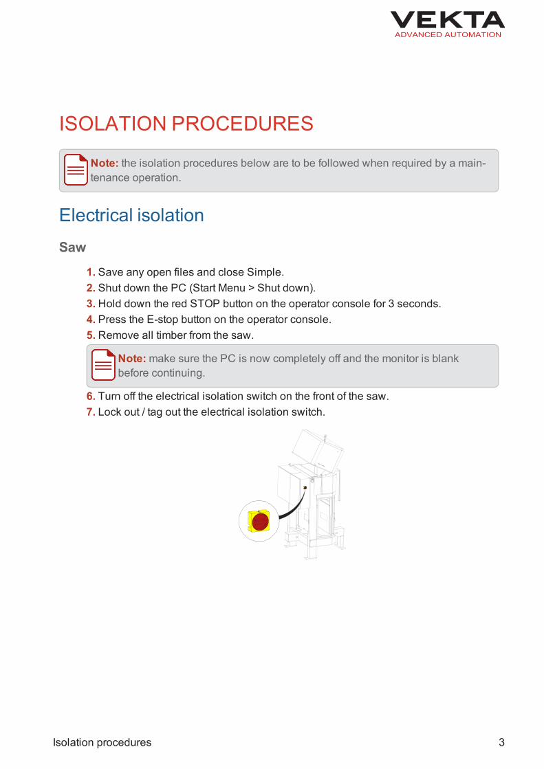
1. Save any open files and close Simple.2. Shut down the PC (Start Menu > Shut down).3. Hold down the red STOP button on the operator console for 3 seconds.4. Press the E-stop button on the operator console.5. Remove all timber from the saw.
Note:make sure the PC is now completely off and the monitor is blankbefore continuing.
6. Turn off the electrical isolation switch on the front of the saw.7. Lock out / tag out the electrical isolation switch.
Isolation procedures 3

Dust Extractor (if required)1. Press the red STOP button on the dust extractor control panel.2. Press the E-stop button on the dust extractor control panel.
3. Isolate the incoming power supply to the dust extractor.4. Lock out / tag out the incoming power supply to the dust extractor.
Pneumatic isolation1. Turn off the pneumatic isolation switch on the pneumatic unit.2. Lock out / tag out the pneumatic isolation switch.
4 Isolation procedures

DAILYClean the print heads
W H A T Y O U N E E D
Safety Equipment:l Standard Personal Protective Equipment
Other Equipment:l Damp lint free clothl Dry lint free cloth
Regular Clean1. Home the saw to ensure the printer is in the full up position.2. Fold a piece of paper towel to a small square, soak with water and squeezeslightly to stop dripping.3.Wipe each protruding print head with the wet paper towel and ensure there is anew and strong double black line on the paper towel from the print head each time.
Thorough Clean (if issue remains with particular print heads)1. Lift the printer cover.2.Make sure the status of both print modules reads "Case open" in the plate markingcontrol panel.3.Open the retention latch for all print heads, not forgetting the side print heads.4. Remove each print head one by one, and clean by dabbing and wiping firmly witha damp lint free cloth. You should get two solid lines of ink.
CAUTIONDo not shake the print heads at any point or this can permanently dam-age them.
5.Make sure no ink or grime is on the electrical contacts behind the print heads.Wipe clean with a dry lint free cloth if required.
Daily 5

6. Refit each print head and close the retention latches fully.
Note: If you have trouble closing a retention latch, re-seat the print head tomake sure it is inserted correctly.
7. Close the printer cover.
Testing1.Make sure the status indicators of all print heads are green in the plate markingcontrol panel.2. If the status indicator of any print head is red or yellow after a couple of minutes, re-clean using the above procedure.3. If a print head is still showing a red or yellow status indicator, replace it with a newone.
If the problem remains in the same slot, the issue is not the print head. CallVekta for assistance solving this issue.If the problem follows the print head, then the print head is faulty. Replace itwith a new one and test again.
6 Daily

Inspect and replace the dust extractor bags
W H A T Y O U N E E D
Tools:l Adjustable Spanner
Spare Parts:l Dust Extractor Bags - ME1192
Safety Equipment:l Standard Personal Protective Equipment
Inspection and replacement1. Press the E-stop button on the operator console.2. Isolate the dust extractor (see page 4).3. Visually inspect the dust extractor for any signs of damage.4. Shake the dust out of the top dust filter bags (if fitted).5.Operate the cleaning mechanism on the side of the dust extractor to clean the cart-ridge filters (if fitted).6. Shake the dust extractor bags to remove excess dust.7. Use an air gun to blow down the dust extractor.8. Unlatch the locking strap on any bag that is full and needs replacing.9. If bags are filling unevenly, adjust the baffles that are used to control the dust flowto each bag:
a. Use a spanner to loosen the exterior nuts that secure the baffle inside the dustextractor above the bag.b. Adjust to direct more or less dust into the bag in question.c. Re-tighten the nuts to secure the baffle in place again.
10. Install new bags using the locking strap, making sure the new bag is in good con-dition.
Testing1. Turn power back on for the dust extractor.2. Release the E-stop button on the dust extractor control panel.3. Release the E-stop button on the operator console.
Daily 7

4. Rehome the saw.5. Using the Manual Mode window, make sure the dust extractor turns on normallyand the bags are filling with air properly.
8 Daily

Inspect and track the waste and extended waste con-veyor belts
W H A T Y O U N E E D
Tools:l Combination Spanner Setl Allen Key Set
Safety Equipment:l Standard Personal Protective Equipment
CAUTIONWhen using the manual mode, make sure that everything and everyone isclear of moving parts to prevent damage or injuries.
Inspection1. Inspect each one of the waste and extended waste conveyors and make sure it isclear of any wedged offcuts or excess build-up.2. Using the Manual Mode window, run the waste conveyors forwards.3. Check the condition of the entire belt on each waste conveyor while it is running,watching for tears and frayed edges.
Note: if the belt is damaged, it should be replaced during the service.
4. Check the tracking of the belt, watching if it runs to one side of the rollers. If thetracking needs to be adjusted, follow the procedure below.
Tracking1. Press the E-stop button on the operator console.2. Extend the M8 tensioning bolts on the bearing blocks to make sure they are tightagainst the push blocks.3. Loosen the three cap head bolts slightly to allow the appropriate bearing blocks tobe adjusted.
Daily 9

4. Slightly extend or retract the tensioning bolts to adjust the roller alignment.
E X A M P L EIf the belt needs to move left, extend the right bearing and/or retract the left bear-ing (ensuring you leave the belt tensioned properly).
5. Tighten the three cap head bolts on each bearing block.6. Tighten the locknut on the tensioning bolts.7. Release the E-stop button on the operator console.8. Rehome the saw.9. Using the Manual Mode window, run the waste conveyors forwards to check thetracking.10. Repeat the tracking procedure if needed.
10 Daily

Daily clean
W H A T Y O U N E E D
Tools:l Air Gun
Safety Equipment:l Standard Personal Protective Equipmentl Eye and Hear Protection
1. Press the E-stop button on the operator console.2. Start the dust extractor manually by pressing the ON button on the dust extractorcontrol panel.3. Blow down the saw chamber, starting at the top and working your way down. Makesure you don't miss any of the following areas:
on top of the Y-axis assemblythrough the centre of the C-axison top of the C-axisaround the B-axis and saw blade
CAUTIONSHARP BLADE: Keep clear of the saw blade while working inside thesaw chamber.
4. Blow down the feeders, ensuring you remove any swarf from the following areas:on top of the side clamp cylindersaround the sides of the chambersaround the six yellow photoelectric sensors in each feederunder the feeders
Note: reach up under the side feeder guards and make sure to removeany dust or swarf that may interfere with the operation of the drive rollersor pop-up encoders.
5.Gently blow down the top of the printer.
CAUTIONDo not blow air onto the print heads.
6. Stop the dust extractor manually by pressing the OFF button on the dust extractorcontrol panel.7. Release the E-stop button on the operator console.
Daily 11

8. Rehome the saw.9. Using the Manual Mode window, start the waste conveyor forwards to remove allthe dust from the bottom of the saw chamber.
12 Daily

General inspection
W H A T Y O U N E E D
Standard Personal Protective Equipment
Inspect the saw chamber:Look for loose or damaged sensors or cables.Look for hydraulic oil around the B-axis, which may indicate a leak.
Inspect both feeders:Look for loose, misaligned or damaged photoelectric sensors.Look for damage on the drive or nylon rollers.
Inspect the Automatic Infeed Table (AIT):Look for damage to the re-ref sensors.Make sure the table sits above the side transfer chains (when in the up position).
Inspect the follower:Look for damage along the edge of the timing belt.Look for damage to the sensor array.
Inspect the side transfer chains:Look for damaged or misaligned chains.Inspect the two gap detection sensors for damage.Make sure the shaft is not damaged.
Inspect the printer:Lift the printer cover and look for loose ribbon cables on the top and side printheads.Make sure the printer encoder is secure and not damaged.
Inspect the Outfeed Kickoff Table (OFK).
Daily 13

This page is intentionally left blank.

WEEKLYClean and inspect the saw chamber door
W H A T Y O U N E E D
Safety Equipment:l Standard Personal Protective Equipment
Other Equipment:l Microfibre clothl Warm soapy water or Windex
1. Using the Manual Mode window, move the saw blade to the back of the saw cham-ber.2. Press the E-stop button on the operator console.3.Open the saw chamber door.4. Start the dust extractor manually by pressing the ON button on the dust extractorcontrol panel.5. Blow off any loose dust or swarf on and around the door.6. Stop the dust extractor manually by pressing the OFF button on the dust extractorcontrol panel.7. Clean off any remaining dust and built-up grime with the microfibre cloth and warmsoapy water. You may soak problem areas for several minutes if required.
CAUTIONl Do not use anything but a microfibre cloth or this will scratch the sur-face of the door and cause it to become cloudy.
l Do not use harsh cleaning products or strong solvents (e.g. acetone)or this will cause the door to become cloudy, brittle and more sus-ceptible to damage.
8. Perform a thorough visual inspection for any bubbles or cracks, paying close atten-tion to the bend in the door.
Note: Please contact Vekta Automation immediately if any defects are foundin the door. It will need to be replaced as soon as possible.
9. Shut the saw chamber door.10. Release the E-stop button on the operator console.
Weekly 15

Inspect the follower
W H A T Y O U N E E D
Standard Personal Protective Equipment
Inspection1. Press the E-stop button on the operator console.2. Perform the following checks:
Make sure the follower carriage is secure by hand (rock the follower side to sideand up and down).Make sure the follower has no apparent loose components (e.g. paddle, sensorbracket, etc.).Inspect the follower timing belt for any signs of damage (e.g. fraying, nicks orcuts).Inspect the follower drag chain, cables and pneumatic hoses for any damage,leaks, nicks or cuts.Inspect the follower home sensor for any signs of damage.Inspect the follower end stops for any signs of damage or bent brackets.
3. Release the E-stop button on the operator console.4. Power the machine back on by pressing the green CONTROL button on the oper-ator console.5.On the sensor array, make sure the green power LED of each sensor is on andtheir orange sensing LED turns on when moving a piece of timber in front of them.
Note: contact Vekta Automation if any of the checks do not look or feel correct.
TestingMake sure the follower rehomes correctly.Make sure the follower slows down before contacting the timber while cutting.
16 Weekly

Inspect and clean the feeder sensors
W H A T Y O U N E E D
Tools:l Allen Key Setl Security Torx Key Setl Small Flat Head Screwdriverl Small Phillips Head Screwdriverl Loctite Low Strength Threadlocker
Spare Parts:l Banner Laser Emitter - EL1023 (if needed)l Banner Receiver - EL1024 (if needed)l Metal Pinhole Mask - EL1022 (if needed)
Safety Equipment:l Standard Personal Protective Equipment
Other Equipment:l Damp cloth
Inspection and cleaning1. Remove both feeder transparent covers.2. Perform the following checks:
Inspect the feeder sensors for any initial signs of damage or misalignment.Make sure the green power LED on each emitter and receiver is on.Check the strength and alignment of the laser beams on the receiver side by pla-cing a thin strip of timber in front of each emitter. The beam should be clearly vis-ible and roughly in the centre of the receiver.Make sure the orange sensing LED on each receiver turns on when the beam isinterrupted.Make sure there is a metal pinhole mask fitted to the first emitter on the infeedfeeder (farthest from the saw chamber) and to the middle emitter on the outfeedfeeder.
3. If any of the checks are not met, press the E-stop button on the operator con-sole and perform the following tasks accordingly:
Replace any damaged or faulty emitters and receivers with spare ones. Apply asmall amount of Loctite on the mounting bolts.
Weekly 17

If the beam is dull, clean the face of the emitter with a damp cloth. Remove any fit-ted mask if necessary and refit after cleaning. If this does not help, replace theemitter with a spare one.If the beam is off centre, adjust the alignment of the emitter.If any metal pinhole mask is missing, install a spare one.
4. Refit both feeder transparent covers.
Testing1. Release the E-stop button on the operator console.2. Feed a long length of timber into the saw by hand and make sure the "eye" feederindicators in the monitoring panel turn grey when the beam is interrupted.
18 Weekly

Inspect and clean the feeder drive rollers
W H A T Y O U N E E D
Tools:l Security Torx Key Setl Flat Head Screwdriverl Air Gun
Safety Equipment:l Standard Personal Protective Equipmentl Safety Gloves
Other Equipment:l Wire brush
Inspection and cleaning
CAUTIONPINCH POINT: Wear safety gloves and rotate the rollers very slowly.
1. Isolate the saw electrically (see page 3).2. Remove both feeder transparent covers.3. Inspect the drive rollers for any signs of damage and make sure they run freely.
Note: contact Vekta Automation if any roller needs to be replaced.
4.With a wire brush, remove any timber shavings and build-up caught in the driveroller knurls.
Note: where the wire brush is not sufficient, a flat head screwdriver can beused.
5. Carefully rotate the drive rollers and continue cleaning until all timber shavings andbuild-up are removed.6. Blow down the feeders around each drive roller.7. Refit both feeder transparent covers.
Weekly 19

Testing
CAUTIONWhen using the manual mode, make sure that everything and everyone isclear of moving parts to prevent damage or injuries.
1. Turn on the electrical isolation switch on the front of the saw.2. Release the E-stop button on the operator console.3. Rehome the saw.4.Open Simple.5. Using the Manual Mode window, operate the drive rollers in both directions.
20 Weekly

Weekly clean
W H A T Y O U N E E D
Tools:l Air Gun
Safety Equipment:l Standard Personal Protective Equipmentl Eye and Hear Protection
Other Equipment:l Step Ladder
1. Using the Manual Mode window, move the Y-axis to the middle position and the Z-axis to the lowest position.2. Press the E-stop button on the operator console.3.Open up the dome.
Note: remove any blocks of wood that may have been thrown up.
4. Start the dust extractor manually by pressing the ON button on the dust extractorcontrol panel.5. Blow down the saw chamber, starting at the top and working your way down. Makesure you don't miss any of the following areas:
on top of the Z-axis assembly and cable traybehind the Y-axis assembly and on top of the cable chain
Note: Pay particular attention to dust accumulating on top of the lowersection of the cable chain. This needs to be cleaned thoroughly.
on top of the Y-axis assemblythrough the centre of the C-axison top of the C-axisaround the B-axis and saw blade
CAUTIONSHARP BLADE: Keep clear of the saw blade while working inside thesaw chamber.
Weekly 21

6. Blow down the feeders, ensuring you remove any swarf from the following areas:on top of the side clamp cylindersaround the sides of the chambersaround the six yellow photoelectric sensors in each feederunder the feeders
Note: reach up under the side feeder guards and make sure to removeany dust or swarf that may interfere with the operation of the drive rollersor pop-up encoders.
7.Gently blow down the top of the printer.
CAUTIONDo not blow air onto the print heads.
8. Stop the dust extractor manually by pressing the OFF button on the dust extractorcontrol panel.9. Close the dome.10. Release the E-stop button on the operator console.11. Rehome the saw.12. Using the Manual Mode window, start the waste conveyor forwards to remove allthe dust from the bottom of the saw chamber.
22 Weekly

MONTHLYGreasing
W H A T Y O U N E E D
Tools:l Allen Key Setl Security Torx Key Setl Flat Head Screwdriverl Grease Gun - ME1122l EPL 2 Lithium Grease - ME1123
Safety Equipment:l Standard Personal Protective Equipment
Other Equipment:l Step Ladderl Rags
Note: A multipurpose high pressure lithium-based grease is required for all linearbearings and ball screw nuts (Castrol Spheerol EPL 2 recommended). The samecan be used for the other bearings but any lithium-based grease will be sufficient.
Grease the Y and Z-axes
CAUTIONWhen using the manual mode, ensure the following:l The appropriate speed slider is set to a very slow speed.l Everything and everyone is clear of moving parts to prevent damage orinjuries.
1. Using the Manual Mode window, move the Y-axis to the middle position and the Z-axis to the lowest position.2.Open up the dome.3. Remove the front and rear frame covers, along with the front and rear end covers ofthe Y-axis assembly.
Monthly 23

4. Using the Manual Mode window, slightly raise the Z-axis, then move the Y-axisacross its range of motion to remove the seven bolts that hold the centre brush coverof the Y-axis assembly, and remove the centre brush cover.5. Using the Manual Mode window, move the Y-axis to the forwardmost position.6. Apply 2-3 pumps of grease to each of the six grease nipples located on top of thesaw and the four grease nipples on the Y-axis linear bearings.
7. Using the Manual Mode window, move the Y and Z-axes to the middle position.8. Apply 2-3 pumps of grease again to the same grease nipples.9. Using the Manual Mode window, move the Y-axis to the rearmost position and theZ-axis to the highest position.10. Apply 2-3 pumps of grease again to the same grease nipples.11.Move the Y and Z-axes several times across their entire range of motion.12. Using the Manual Mode window, move the Y-axis across its range of motion torefit the centre brush cover on the Y-axis assembly and tighten the seven bolts thathold it in place.13. Refit the front and rear frame covers, along with the front and rear end covers ofthe Y-axis assembly.14. Using the Manual Mode window, move the Y-axis to the middle position and theZ-axis to the lowest position.15. Close the dome.
24 Monthly
Grease the feeders1. Press the E-stop button on the operator console.2. Remove the side feeder guards on both sides of each feeder.3. Apply 2-3 pumps of grease to the eight grease nipples on the drive roller bearings.
Note: you may need to get under each feeder to reach the four drive rollerbearings closest to the saw chamber.
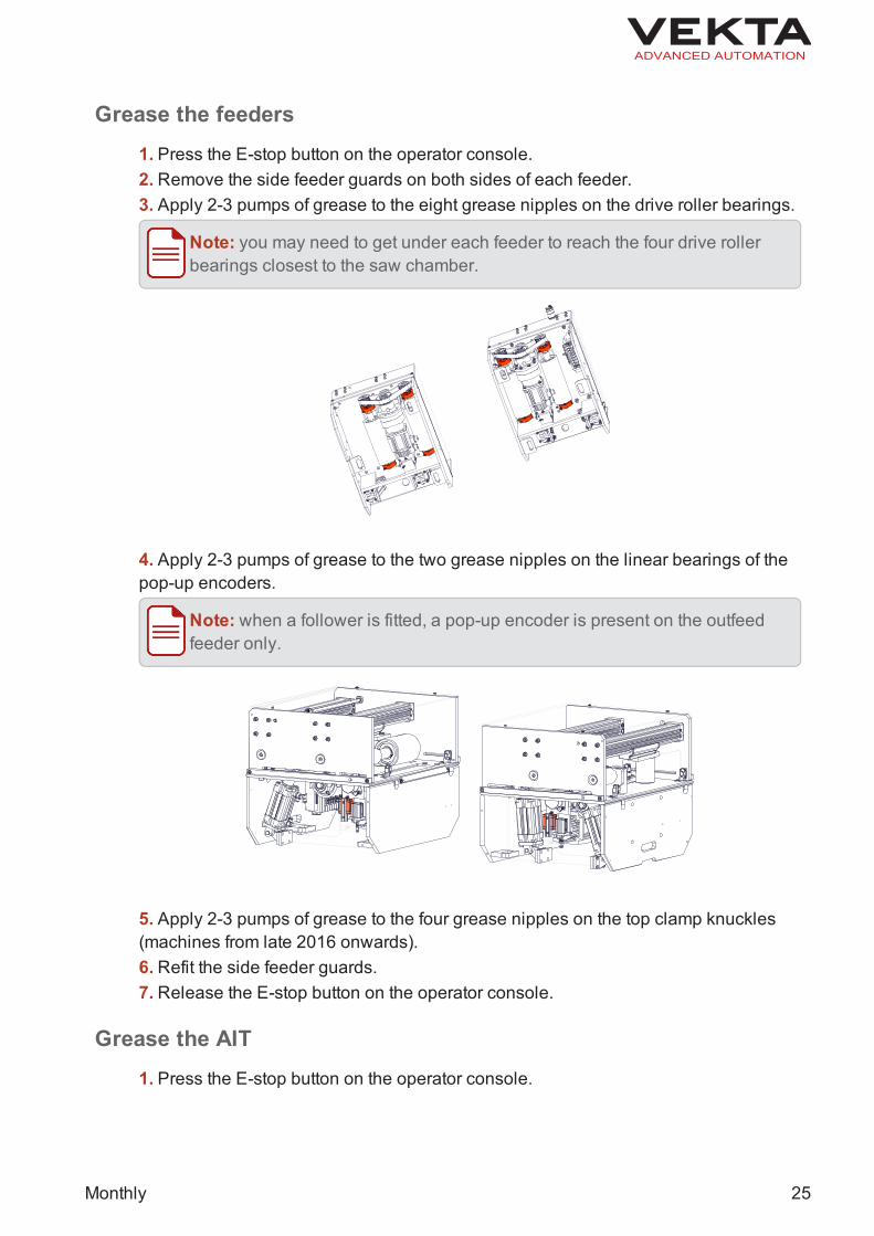
4. Apply 2-3 pumps of grease to the two grease nipples on the linear bearings of thepop-up encoders.
Note: when a follower is fitted, a pop-up encoder is present on the outfeedfeeder only.
5. Apply 2-3 pumps of grease to the four grease nipples on the top clamp knuckles(machines from late 2016 onwards).6. Refit the side feeder guards.7. Release the E-stop button on the operator console.
Grease the AIT1. Press the E-stop button on the operator console.
Monthly 25

2. Apply 2-3 pumps of grease to the three grease nipples on the roller bearings of theside transfer legs.
3. Apply 2-3 pumps of grease to the eight grease nipples on the linear bushings atthe rear of the AIT.
4. Release the E-stop button on the operator console.
Grease the follower1. Rehome the saw if not already in the home position (follower farthest from the sawchamber).2.Old follower (manufactured prior to September 2016): Apply 1 pump of grease tothe two grease nipples on the carriage linear bearings.2. New follower (manufactured from September 2016): Apply 1 pump of grease to thegrease nipple on the shuttle plate.
26 Monthly

3. Start a rehoming cycle then press the red STOP button on the operator consolewhen the follower is half-way up the rail.4. Apply 1 pump of grease again to the same grease nipple(s).5. Perform 3 rehoming cycles to distribute the grease along the follower rail.6. Apply 2-3 pumps of grease to the two grease nipples on the paddle linear bear-ings.
7.Wipe off any excess grease.
Grease the P3 printer1. Press the E-stop button on the operator console.2. Lift the printer cover.3. Apply 2-3 pumps of grease to the two grease nipples on the carriage linear bear-ings.
Monthly 27

4. Close the printer cover.5. Release the E-stop button on the operator console.
Grease the OFK1. Press the E-stop button on the operator console.2. Apply 2-3 pumps of grease to the six grease nipples on the conveyor roller bear-ings.
Note: you may need to lift the printer cover to reach the two conveyor rollerbearings closest to the saw chamber.
3. Release the E-stop button on the operator console.
Grease the waste and extended waste conveyors1. Press the E-stop button on the operator console.2. Apply 2-3 pumps of grease to the four grease nipples on the roller bearings of thewaste conveyor under the saw chamber.
28 Monthly

3. Apply 2-3 pumps of grease to the grease nipples (four per conveyor) on the rollerbearings of the extended waste conveyor(s).4. Release the E-stop button on the operator console.
Testing1.Make sure all axes rehome correctly.2. Start a cutting sequence with normal sticks of timber from an optimised job file andmake sure everything runs smoothly.
Monthly 29

Check the AIT chain tensions
W H A T Y O U N E E D
Tools:l 24-mm Combination Spanner
Safety Equipment:l Standard Personal Protective Equipmentl Safety Gloves
Check and correct the chain tension on the side transfer legs1. Press the E-stop button on the operator console.2. In the centre of each side transfer legs, lift up the chain to test the tension.
Note: there should not be more than 75 mm of deflection in the chain.
3. Inspect the chain for signs of wear and for any rubbish or bits of timber that maycause the side transfer to pinch.4. If a side transfer chain is loose, do the following:
a. Loosen the locknut on both tensioning bolts at the end of the side transfer leg(roller conveyor side).b. Evenly tighten both tensioning bolts to tension the chain.c. Check the chain tension after each small adjustment.d. Tighten the locknut on both tensioning bolts.
Check the chain tension on the infeed roller conveyor1. Press the E-stop button on the operator console.
30 Monthly

2. Rotate one conveyor roller back and forth to feel for any excessive backlash.
Note: there should not be more than 1 or 2 mm of backlash.
3. Inspect the chain for signs of wear and for any rubbish or bits of timber that maycause the roller conveyor to pinch.4. If the roller conveyor chain is loose, do the following:
a. Loosen the AIT motor mounting bolts.b. Adjust the chain tension by lowering or raising the AIT motor slightly.c. Check the chain tension after each small adjustment.d. Tighten the AIT motor mounting bolts.
Note: you may need to contact a Vekta Automation for assistance in ten-sioning the chain.
Testing
CAUTIONWhen using material handling in the manual mode, make sure that everythingand everyone is clear of moving parts to prevent damage or injuries.
1. Release the E-stop button on the operator console.2. Rehome the saw.3.Open Simple.
4. In the Material Handling window, click to operate the side transferlegs and check for any misalignment.
5. Click under AIT Infeed Control to operate the infeed roller conveyorand check for any misalignment.
Monthly 31

Inspect the feeder nylon rollers
W H A T Y O U N E E D
Tools:l Security Torx Key Set
Safety Equipment:l Standard Personal Protective Equipment
Note: there are four side fence rollers, two side clamp rollers and two top clamprollers in each feeder, which makes a total of 16 nylon rollers.
Inspection1. Using the Manual Mode window, move the saw blade to the back of the saw cham-ber.2. Isolate the saw electrically (see page 3).3. Remove both feeder transparent covers.4. Inspect the nylon rollers for any signs of damage, wear or flat spots.5.Gently move the 12 side rollers up and down, and the four top rollers sideways tomake sure they have a small amount of play.6.Make sure they run freely and there is no sign of sticking.
Note: If any roller or roller bearing needs to be replaced, contact Vekta Auto-mation.
7. Refit both feeder transparent covers.
Testing
CAUTIONWhen using the manual mode, make sure that everything and everyone isclear of moving parts to prevent damage or injuries.
1. Turn on the electrical isolation switch on the front of the saw.2. Release the E-stop button on the operator console.3. Rehome the saw.4.Open Simple.
32 Monthly

5. Using the Manual Mode window, feed in a stick of timber and make sure it feedscorrectly.
Monthly 33

Clean the fan filters and electrical cabinets
W H A T Y O U N E E D
Tools:l Large Flat Head Screwdriverl Air Gun
Safety Equipment:l Standard Personal Protective Equipment
Other Equipment:l Electrical cabinet door key
1. Isolate the saw and the dust extractor electrically (see page 3).2. Blow air towards the ground for several seconds to make sure there is no moistureleft in the air gun.3. Using a flat head screwdriver, remove the front covers off all fan vents to accessthe fan vent filters.4. Blow all dust out of the filters and vents.5. Refit all vent covers.
Note:make sure the filter is flat in the vent covers.
6.Open each electrical cabinet and inspect for any build-up of dust.7. If there is excessive dust, gently blow dry air in and around the cabinet from top tobottom.
CAUTIONDo not blow air directly onto exposed electrical components.
8.Gently blow the dust off the electrical fans.9.Once all dust has been removed, close and lock each electrical cabinet.
34 Monthly

Monthly clean
W H A T Y O U N E E D
Tools:l Security Torx Key Setl Allen Key Setl Air Gun
Safety Equipment:l Standard Personal Protective Equipmentl Eye and Hear Protection
Other Equipment:l Step Ladder
1. Using the Manual Mode window, move the Y-axis to the middle position and the Z-axis to the lowest position.2. Isolate the saw electrically (see page 3).3.Open up the dome.4. Remove the side feeder guards.5. Remove the front and rear end covers of the Y-axis assembly.6. Start the dust extractor manually by pressing the ON button on the dust extractorcontrol panel.7. Blow down the saw chamber, starting at the top and working your way down. Makesure you don't miss any of the following areas:
on top of the Z-axis assembly and cable traybehind the Y-axis assembly and on top of the cable chain
Note: Pay particular attention to dust accumulating on top of the lowersection of the cable chain. This needs to be cleaned thoroughly.
on top of the Y-axis assemblythrough the centre of the C-axison top of the C-axisaround the B-axis and saw blade
CAUTIONSHARP BLADE: Keep clear of the saw blade while working inside thesaw chamber.
Monthly 35

8. Blow all dust and swarf out of the Y-axis assembly from front to rear.
Note:make sure to remove any dust or swarf that may interfere with the oper-ation of the linear bearings or ball screw nut.
9. Blow down the feeders, ensuring you remove any swarf from the following areas:on top of the side clamp cylindersaround the sides of the chambersaround the six yellow photoelectric sensors in each feederunder the feeders
Note:make sure to remove any dust or swarf that may interfere with theoperation of the drive rollers or pop-up encoders.
10.Gently blow down the top of the printer.
CAUTIONDo not blow air onto the print heads.
11. Stop the dust extractor manually by pressing the OFF button on the dust extractorcontrol panel.12. Refit the front and rear end covers of the Y-axis assembly.13. Refit the side feeder guards.14. Close the dome.15. Turn on the electrical isolation switch on the front of the saw.16. Release the E-stop button on the operator console.17. Rehome the saw.18.Open Simple.19. Using the Manual Mode window, start the waste conveyor forwards to remove allthe dust from the bottom of the saw chamber.
36 Monthly

This page is intentionally left blank.

Copyright © 2020 Vekta Automation Pty Ltd.All rights reserved.
Information in this document is subject to change without notice. No part of this publicationmay be reproduced, stored in a retrieval system, or transmitted in any form or any meanselectronic or mechanical, including photocopying and recording for any purpose other thanthe purchaser's personal use without the written permission of Vekta Automation Pty Ltd.
Vekta Automation Pty Ltd85 Beringarra AvenueMalaga WA 6090+61 8 6117 0660