operator’s manual - thermoking.com · temperature control and trane, a provider of energy effi...
TRANSCRIPT

Operator’s Manual
Operator’s Manual
Ingersoll Rand’s Climate Solutions sector delivers energy-effi cient HVACR solutions for customers globally. Its world class brands include Thermo King, the leader in transport temperature control and Trane, a provider of energy effi cient heating, ventilating and air conditioning systems, building and contracting services, parts support and advanced controls for commercial buildings and homes.
Ingersoll Rand’s Climate Solutions sector delivers energy-effi cient HVACR solutions for customers globally. Its world class brands include Thermo King, the leader in transport temperature control and Trane, a provider of energy effi cient heating, ventilating and air conditioning systems, building and contracting services, parts support and advanced controls for commercial buildings and homes.
©2013 Ingersoll-Rand Company Printed in U.S.A.
©2013 Ingersoll-Rand Company Printed in U.S.A.
TriPac EVOLUTIONDiesel Particulate Filter
(DPF)
TK 56295-19-OP (Rev. 2, 03/16)
TriPac EVOLUTIONDiesel Particulate Filter
(DPF)
TK 56295-19-OP (Rev. 2, 03/16)


Copyright© 2013 Thermo King Corp., Minneapolis, MN, USAPrinted in USA
TriPac™ EVOLUTIONwith
Diesel Particulate Filter (DPF)TK 56295-19-OP (Rev. 2, 03/16

2
DisclaimerThis manual is published for informational purposes only. Thermo King Corporation makes no representations orwarranties, express or implied, with respect to the information, recommendations and descriptions contained in this manualand such information, recommendations and descriptions should not be regarded as all-inclusive or covering allcontingencies. In the event you have any questions or require further information, please contact your local Thermo Kingdealer.
The procedures described herein should only be undertaken by suitably qualified personnel. Failure to implement theseprocedures correctly may cause damage to the Thermo King unit or other property or personal injury.
Thermo King Corporation and its affiliates shall have no liability in contract or tort (including negligence and/or strictliability) or otherwise, to any person or entity for any personal injury, property damage or any other direct, indirect, specialor consequential damage or liability whatsoever, arising out of or resulting from any actions by any person that are contraryto this manual or any of the information, recommendations or descriptions contained herein or the failure of any person toimplement the procedures described herein correctly or to follow caution and safety decals located on the Thermo Kingunit.

3
Table of ContentsIntroduction . . . . . . . . . . . . . . . . . . . . . . . . . . . . . . . . . 6
Safety Precautions . . . . . . . . . . . . . . . . . . . . . . . . . . . 7General Practices . . . . . . . . . . . . . . . . . . . . . . . . . . . . . 7
Burn Hazard . . . . . . . . . . . . . . . . . . . . . . . . . . . . . . 8Fire Hazard . . . . . . . . . . . . . . . . . . . . . . . . . . . . . . . 8Hazardous Material . . . . . . . . . . . . . . . . . . . . . . . . 8
TriPac Unit Description . . . . . . . . . . . . . . . . . . . . . . . 9Standard Features . . . . . . . . . . . . . . . . . . . . . . . . . . . 10System Components . . . . . . . . . . . . . . . . . . . . . . . . . . 10
Auxiliary Power Unit (APU) . . . . . . . . . . . . . . . . . . 10Condenser . . . . . . . . . . . . . . . . . . . . . . . . . . . . . . 11Evaporator . . . . . . . . . . . . . . . . . . . . . . . . . . . . . . 11Heater . . . . . . . . . . . . . . . . . . . . . . . . . . . . . . . . . . 12HMI Controller . . . . . . . . . . . . . . . . . . . . . . . . . . . 12Engine On/Off Switch . . . . . . . . . . . . . . . . . . . . . . 13Control Box and Fuses . . . . . . . . . . . . . . . . . . . . . 13Standby Truck Integration with Dash-Mounted Selector Switch (Option) . . . . . . . . . . . . . . . . . . . . 14
DPF Description . . . . . . . . . . . . . . . . . . . . . . . . . . . . .15DPF System Components . . . . . . . . . . . . . . . . . . . . . .16DPF Canister . . . . . . . . . . . . . . . . . . . . . . . . . . . . . . . .16DPF Exhaust Monitor . . . . . . . . . . . . . . . . . . . . . . . . . .17Regeneration Switch . . . . . . . . . . . . . . . . . . . . . . . . . .18Control Module Assembly . . . . . . . . . . . . . . . . . . . . . .18Valve Box . . . . . . . . . . . . . . . . . . . . . . . . . . . . . . . . . . .19Protection Devices . . . . . . . . . . . . . . . . . . . . . . . . . . . .19
Battery Voltage Monitoring . . . . . . . . . . . . . . . . . .19On-Board Diagnostic System . . . . . . . . . . . . . . . .19Fuses . . . . . . . . . . . . . . . . . . . . . . . . . . . . . . . . . . .20Relays . . . . . . . . . . . . . . . . . . . . . . . . . . . . . . . . . .20
Manual Pretrip Inspection . . . . . . . . . . . . . . . . . . . . .21
TriPac Operating Instructions . . . . . . . . . . . . . . . . .22HMI Control Panel Display . . . . . . . . . . . . . . . . . . . . . .22
On/Off Button . . . . . . . . . . . . . . . . . . . . . . . . . . . .23Mode Selector . . . . . . . . . . . . . . . . . . . . . . . . . . . .23Temperature Selector . . . . . . . . . . . . . . . . . . . . . .24

Table of Contents
4
Fan Speed Selector . . . . . . . . . . . . . . . . . . . . . . . 25System Condition . . . . . . . . . . . . . . . . . . . . . . . . . 25Standby Indicator . . . . . . . . . . . . . . . . . . . . . . . . . 25Alarm Icon . . . . . . . . . . . . . . . . . . . . . . . . . . . . . . . 26Alarm Group Indicator . . . . . . . . . . . . . . . . . . . . . . 26Clearing Alarms . . . . . . . . . . . . . . . . . . . . . . . . . . 26
Operating Modes . . . . . . . . . . . . . . . . . . . . . . . . . . . . . 26Cool Mode . . . . . . . . . . . . . . . . . . . . . . . . . . . . . . . 26Heat Mode . . . . . . . . . . . . . . . . . . . . . . . . . . . . . . 27Fan Mode . . . . . . . . . . . . . . . . . . . . . . . . . . . . . . . 27Standby Mode (Option) . . . . . . . . . . . . . . . . . . . . . 28Standby Truck Integration (Option) . . . . . . . . . . . . 28Standby Truck Integration - with Dash-Mounted Selector Switch (Option) . . . . . . . . . . . . . . . . . . . . 29
Monitor Mode . . . . . . . . . . . . . . . . . . . . . . . . . . . . . . . . 29Activate . . . . . . . . . . . . . . . . . . . . . . . . . . . . . . . . . 29Deactivate . . . . . . . . . . . . . . . . . . . . . . . . . . . . . . . 29Operation . . . . . . . . . . . . . . . . . . . . . . . . . . . . . . . 29
Engine Load Management . . . . . . . . . . . . . . . . . . . . . 30Engine On/Off Switch . . . . . . . . . . . . . . . . . . . . . . . . . 30
DPF Regeneration Switch . . . . . . . . . . . . . . . . . . . 31Alarm Codes . . . . . . . . . . . . . . . . . . . . . . . . . . . . . . . . 32
Alarm Notification . . . . . . . . . . . . . . . . . . . . . . . . . 32To Clear Alarm Codes . . . . . . . . . . . . . . . . . . . . . 33
DPF Operating Instructions . . . . . . . . . . . . . . . . . . . 34Introduction . . . . . . . . . . . . . . . . . . . . . . . . . . . . . . . . . 34When to Regenerate . . . . . . . . . . . . . . . . . . . . . . . . . 34Initiating a DPF Regeneration . . . . . . . . . . . . . . . . . . 35
Regeneration Switch . . . . . . . . . . . . . . . . . . . . . . 35To cancel a regeneration . . . . . . . . . . . . . . . . . . . 36
Indicator Light System . . . . . . . . . . . . . . . . . . . . . . . . 37No Indicator Light . . . . . . . . . . . . . . . . . . . . . . . . . 38Steady Amber Indicator Light . . . . . . . . . . . . . . . . 38Flashing Amber Indicator Light . . . . . . . . . . . . . . 38Flashing Red Indicator Light . . . . . . . . . . . . . . . . 39
DPF Indicator Light Quick Reference Chart . . . . . . . . 40
DPF Fault Codes . . . . . . . . . . . . . . . . . . . . . . . . . . . . 41DPF Fault Code Chart . . . . . . . . . . . . . . . . . . . . . . . . 42Clearing DPF Fault Codes . . . . . . . . . . . . . . . . . . . . . 44
Specifications . . . . . . . . . . . . . . . . . . . . . . . . . . . . . . 45Engine . . . . . . . . . . . . . . . . . . . . . . . . . . . . . . . . . . . . 45TriPac Electrical Control System . . . . . . . . . . . . . . . . 46TriPac Fuses . . . . . . . . . . . . . . . . . . . . . . . . . . . . . . . 47DPF Electrical Control System . . . . . . . . . . . . . . . . . . 48Air Conditioning System . . . . . . . . . . . . . . . . . . . . . . . 49Truck Sleeper Compartment Heater . . . . . . . . . . . . . 49

Table of Contents
5
Maintenance Inspection Schedule . . . . . . . . . . . . . 50Engine Operation . . . . . . . . . . . . . . . . . . . . . . . . . . . . 50
Diesel Fuel . . . . . . . . . . . . . . . . . . . . . . . . . . . . . . 50Engine Oil . . . . . . . . . . . . . . . . . . . . . . . . . . . . . . . 50Injectors . . . . . . . . . . . . . . . . . . . . . . . . . . . . . . . . 51DPF Canister . . . . . . . . . . . . . . . . . . . . . . . . . . . . 51
Air Conditioning System . . . . . . . . . . . . . . . . . . . . . . . 51Truck Sleeper Compartment Heater . . . . . . . . . . . . . . 51Engine Maintenance Schedule . . . . . . . . . . . . . . . . . . 52Engine Oil Change Intervals . . . . . . . . . . . . . . . . . . . . 54TriPac Electrical . . . . . . . . . . . . . . . . . . . . . . . . . . . . . 55TriPac Structural . . . . . . . . . . . . . . . . . . . . . . . . . . . . . 56DPF Structural . . . . . . . . . . . . . . . . . . . . . . . . . . . . . . 56Air Conditioning System . . . . . . . . . . . . . . . . . . . . . . . 57Heater . . . . . . . . . . . . . . . . . . . . . . . . . . . . . . . . . . . . . 58
Diesel Emission Warranty . . . . . . . . . . . . . . . . . . . . 59
Serial Number Locations . . . . . . . . . . . . . . . . . . . . . 62
Emergency Cold Line . . . . . . . . . . . . . . . . . . . . . . . . 63
Recover Refrigerant . . . . . . . . . . . . . . . . . . . . . . . . . 64
CALIFORNIA Proposition 65 Warning . . . . . . . . . . . 65

6
IntroductionTaking the time to read this manual will help in understanding how to properly operate, service and maintain your Thermo King Diesel Particulate Filter (DPF) system.
Performing pre-trip checks and enroute inspections on a regular basis will minimize on-the-road operating problems. A regular maintenance program will also help to keep your DPF system in top operating condition. When factory recommended procedures are followed, you will find that you have purchased the most efficient and dependable diesel particulate filter system available. All service requirements, major and minor, should be handled by a Thermo King dealer for four very important reasons:
• They are equipped with the factory recommended tools to perform all service functions
• They have factory trained and certified technicians
• They have genuine Thermo King replacement parts
• The warranty on your new DPF system is valid only when the repair and replacement of component parts is performed by an authorized Thermo King dealer.
When the DPF system and it’s components are installed onto a Thermo King TriPac APU diesel engine, the emission control level will conform to the California Air Resource Board (CARB) Airborne Toxic Control Measure (ATCM), and is warranted for a period of 3-years or 1600- hours, which ever comes first, as it applies to Auxiliary Power Units (APU). See “Diesel Emission Warranty” on page 59 for complete details.
IMPORTANT: This manual is published for informational purposes only and the information furnished herein should not be considered as all-inclusive or meant to cover all contingencies. If more information is required, consult your Thermo King Service Directory for the location and telephone number of the local dealer.

7
Safety PrecautionsThermo King recommends that servicing be done only by an authorized Thermo King dealer. However, there are several general safety precautions that you should become familiar regarding the Thermo King Diesel Particulate Filter (DPF).
The warning symbol appears next to a point that is particularly important:
General Practices
DANGER: Addresses a circumstance that, if encountered, will lead to death or serious injury.
WARNING: Addresses a circumstance that, if encountered, might lead to death or serious injury.
CAUTION: Addresses a circumstance that, if encountered, may cause damage to equipment or minor injury.
DANGER: Always turn the TriPac unit off while refueling the truck. Fuel vapors could ignite if they come in contact with TriPac electrical or heater components.
WARNING: Turn the TriPac unit On/Off switch to the Off position before inspecting any part of the APU or the Diesel Particulate Filter (DPF) components.
WARNING: Disconnect the positive power cable from the truck’s battery to the Diesel Particulate Filter (DPF) before servicing any of it’s components.

Safety Precautions
8
Burn Hazard
Fire Hazard
Hazardous Material
WARNING: The Diesel Particulate Filter (DPF) canister, exhaust system components and exhaust discharge at the tail pipe can get extremely hot and could cause serious burns to the skin.
WARNING: The Diesel Particulate Filter (DPF) canister, exhaust system components and exhaust discharge at the tail pipe can get extremely hot and could ignite a fire if placed in close proximity with combustibles such as dry grass, paper or leaves.
WARNING: The Diesel Particulate Filter (DPF) accumulates ash that may be considered hazardous material and must be disposed of in accordance with all applicable Federal, State, and local laws.

9
TriPac Unit DescriptionThe Thermo King TriPac EVOLUTION APU (Auxiliary Power Unit) provides auxiliary heating, cooling temperature management that allows drivers to reduce unnecessary truck engine idling, conserve diesel fuel and save money. TriPac EVOLUTION provides truck engine preheating, battery charging and truck cab sleeper compartment climate control.
By using TriPac, drivers can reduce fuel cost, rest comfortably during stops and comply with local, state and federal anti-idle laws. Reducing unnecessary truck engine idling also reduces engine wear and extends engine maintenance intervals. TriPac’s own diesel engine uses an automatic start/stop feature for additional fuel efficiency.
TriPac’s two-cylinder diesel engine is EPA Tier 4 approved. An automotive type air conditioning compressor is used for sleeper compartment cooling. A fuel-fired air heater provides sleeper compartment heat in cold conditions. Voltage sensing automatically charges the truck batteries from TriPac’s 12-volt alternator. Noise dampening construction assures quiet operation. Truck engine preheating provides easier cold-climate starts by exchanging coolant between TriPac and
the truck engine. An optional inverter provides 120-volt power to operate on-board appliances. An optional Arctic package aids truck engine startups in cold weather by sensing low coolant temperature. The TriPac is started automatically to heat the coolant as required.
For units equipped with a Diesel Particulate Filter (DPF), See “DPF Description” on page 15.
TriPac EVOLUTION APU

TriPac Unit Description
10
Standard Features• Human Machine Interface (HMI) Controller
• Truck cab sleeper compartment cooling and heating for driver comfort in all climates
• Truck engine preheating for easy starts in cold climates
• Truck battery charging with automatic low voltage sensing
• 9.0 hp 2 cylinder diesel engine - EPA Tier 4• Thermo King TK 15 compressor for air conditioning
• Diesel fuel-fired sleeper compartment air heater
• 65 amp alternator standard
• Noise-dampening construction for quiet operation
• Automatic start/stop operation for maximum fuel efficiency
System Components• Auxiliary Power Unit (APU)• Condenser
• Evaporator
• Heater
• HMI Controller
• Engine On/Off Switch
• Control Box and Fuses
Auxiliary Power Unit (APU)The TriPac EVOLUTION APU is mounted onto the side of the tractor’s frame rails and contains the diesel engine, air conditioning compressor, alternator and engine On/Off switch.
TriPac EVOLUTION APU

TriPac Unit Description
11
Condenser The TriPac air conditioning condenser is typically mounted on the outside rear wall of the truck cab.
TriPac Condenser
EvaporatorThe TriPac air conditioning evaporator is typically installed under the bunk in the truck cab sleeper compartment. Air ducts from the evaporator carry conditioned air to the sleeper compartment. The evaporator has a air filter that can easily removed for cleaning.
TriPac Evaporator and Air Ducts

TriPac Unit Description
12
HeaterThe TriPac heater is typically installed in the cargo compartment or under the truck cab sleeper compartment. It draws fuel from the truck’s diesel fuel tank and is powered by the truck’s batteries.
Heater
HMI Controller
The TriPac HMI controller is installed in the truck cab, typically on a wall in the sleeper compartment. It is easily accessible to the driver and controls the heating, cooling and fan operation of the TriPac. If necessary, system operating parameters can be programmed by your Thermo King dealer.
HMI Controller
DANGER: Always turn the TriPac HMI Controller OFF while refueling the truck. Fuel vapors could ignite if they come in contact with TriPac electrical or heater components.

TriPac Unit Description
13
Engine On/Off SwitchThe APU Engine On/Off Switch is located inside the TriPac APU housing on the lower right side of the frame. This switch is used to disable the engine when performing service and maintenance on the TriPac system. The switch is normally in the ON position to allow the TriPac system to operate.
Engine On/Off Switch
Control Box and FusesThe control box is typically located in the bunk area. The control box contains the circuit board and operates on 12 Volt DC supplied by the truck batteries.
The electrical system is protected by a number of fuses. Most of the fuses are located inside the control box. Other fuses are located in fuse holders in wire harnesses. See “TriPac Fuses” on page 47.
Control Box
ARA2105

TriPac Unit Description
14
Standby Truck Integration with Dash-Mounted Selector Switch (Option)This optional switch allows the operator to disable the TriPac system without accessing the HMI Control Panel in the sleeper.
Dash-Mounted Standby Switch

15
DPF DescriptionThe Thermo King Diesel Particulate Filter (DPF) is designed to reduce the particulate matter output from the TriPac APU’s diesel engine. When the TriPac’s APU is operating, the DPF control system monitors the APU’s diesel engine exhaust. The DPF canister captures the particulate matter from the APU’s engine exhaust and the control system alerts the driver when to initiate the regeneration process to clean the particulate matter (soot) from the filter. The driver initiates the regeneration by activating the dash-mounted regeneration switch. After approximately 1 to 2 hours, the regeneration process is complete, the indicator lights go out and the APU is ready to operate again. This process will be repeated after the APU has been operated again for a period of time. The DPF system replaces the standard APU muffler and exhaust system and includes a Solid State Control Module, Valve Box, Exhaust Monitor and a dash-mounted Regeneration Switch.
IMPORTANT: The DPF system operates using electrical voltage supplied by the truck’s alternator system. Due to the large current draw required by the DPF, the regeneration process should only be initiated during daytime hours while the truck is expected to be operating at highway speeds (above 1150 rpm) for a minimum of one hour. Do not operate the DPF while the truck is stopped, idling or moving slowly in traffic. If this condition occurs, the regeneration process may automatically be cancelled.
NOTE: The TriPac APU will be disabled when the DPF is in the regeneration mode or if the DPF regeneration switch is in the OFF position.

DPF Description
16
DPF System Components• Stainless Steel DPF canister and exhaust components
• DPF Exhaust Monitor
• DPF Regeneration Switch
• Solid State Control Module Assembly with On-board Diagnostic System.
• Corrosion resistant Valve Box.
DPF CanisterThe DPF canister is typically mounted to the rear of the APU in place of the standard exhaust and muffler system. The exhaust particulate matter that is captured and retained in the DPF canister is burned off during the regeneration process.
DPF canister mounted onto the rear of a TriPac APU

DPF Description
17
DPF Exhaust MonitorThe DPF Exhaust Monitor is typically mounted in the bunk area of the tractor. Two indicator lights are displayed on the monitor to alert the driver when to initiate a regeneration, when a regeneration is in process, or when a fault has been detected by the on-board diagnostic system. These lights not only help the driver determine when to initiate the regeneration, but also identify any problems that may have been detected by the on-board diagnostic system. The red DPF Fault and amber DPF Status indicator lights are displayed on the Exhaust Monitor, while only the amber DPF Status indicator light is displayed on the Regeneration Switch.
When no indicator light is displayed, the DPF system has not detected any need to initiate a regeneration and the TriPac APU can be operated as usual.
Red DPF Fault Indicator Light
Amber DPF Status Indicator Light

DPF Description
18
Regeneration SwitchThe DPF Regeneration Switch is typically mounted in the truck’s instrument panel. The switch allows the driver to initiate a regeneration or to cancel the regeneration if necessary. The switch has an amber indicator light which illuminates when a regeneration is required.
NOTE: The TriPac APU will be disabled when the DPF is in the regeneration mode or if the DPF regeneration switch is in the OFF position.
Amber Indicator Light Location on Switch
Control Module AssemblyThe Control Module Assembly is typically mounted on top or near the existing TriPac control box and is connected to the TriPac’s control system. The control module monitors the APU’s exhaust and operates the DPF system components. The control module also includes an on-board diagnostic system used for diagnostic and maintenance purposes.
1. TriPac Control Box 2. Control Module Assembly
Control Module Assembly
1
2

DPF Description
19
Valve BoxThe Valve Box is mounted on the exterior of the truck and contains an electrical contactor, air solenoid and blower motor. These components are used to operate the DPF system.
Valve Box shown mounted on exterior of truck
Protection Devices
Battery Voltage Monitoring The DPF control system monitors the truck’s battery voltage and stops the regeneration process if the voltage raises or drops below a safe operating level.
On-Board Diagnostic System The DPF controller includes an on-board diagnostic system that monitors the TriPac’s APU diesel engine exhaust and the operation of the DPF regeneration process. If a problem is detected while in the regeneration mode, the on-board diagnostic system will display the WARNING or SHUTDOWN fault code(s) for diagnostic purposes. Additionally, if a SHUTDOWN code is detected, the system will shutdown and disable both the DPF and the TriPac system from operating.

DPF Description
20
Fuses Three fuses are used to protect the DPF components:
Main Fuse: A 150 amp fuse protects the DPF canister from shorts. The fuse is located on the positive battery cable, near the truck’s battery.
Ignition Switch Fuse: A 1 amp fuse protects the ignition wire input from shorts. The fuse is located in-line and typically is connected to the truck’s ''SWITCHED POWER'' side of the ignition system.
Control Module Fuse: A 10 amp fuse protects the control module from shorts. The fuse is located inside the valve box.
RelaysFour relays are used to operate the components of the DPF system. The relays are located on the Control Module Assembly panel inside the truck.
Control Module Assembly and Relays
21
Manual Pretrip InspectionComplete TriPac pretrip inspections are an important part of a preventative maintenance program designed to minimize operating problems and breakdowns. Perform this pretrip inspection before every trip.
NOTE: Pretrip inspections are not intended to take the place of regular maintenance inspections.
Before Starting the TriPac Unit:TriPac Engine: Check engine oil and coolant levels.
TriPac Belts: Make sure the TriPac APU belts are in good condition and adjusted to the proper tension.
TriPac and DPF Electrical: Check the electrical connections to make sure they are securely fastened. Wires and terminals should be free of corrosion, cracks, and moisture.
TriPac and DPF Structural: Visually inspect both the unit and DPF for leaks, loose or broken parts, and other damage.
TriPac Coils: Make sure the condenser, evaporator and pre-cooler coils are clean and free of debris.
TriPac Heater: Check exhaust pipe and intake tube to be sure they are secured properly and the inlet and outlets are not obstructed.
General: Listen for unusual noises and vibrations.

22
TriPac Operating InstructionsThe HMI (Human Machine Interface) is typically mounted in the bunk area of the truck cab. The operator can select the desired function of the system. It has three selector knobs and system condition display. The HMI contains the Cab Temperature Sensor. It communicates with the Controller using the Controller Area Network (CAN).
HMI Controller
HMI Control Panel DisplayThe operator can select these functions from the HMI:
• System On/Off
• Mode (Cool, Fan, Heat)
• Cab Temperature (Cooler/Blue-Warmer/Red)
• Fan Speed (Off, Low, Medium, High)
When any change of settings is made there is a two second delay before the controller will recognize the new setting. This prevents momentary or accidental mode changes.
The HMI indicator LEDs will dim after 90 seconds if no selections are made. Bump the On/Off button to activate bright display for an additional 90 seconds.

TriPac Operating Instructions
23
On/Off Button The On/Off Button is behind the left knob on the HMI. It provides several functions depending on how long the button is pressed.
Press Button for ON or OFF
Turn system On: If the system is off, press the Mode Selector knob for a minimum of 1 second to turn the system on. The mode icon will flash for 10 seconds while the controller completes a boot process. Once the system has been turned on the system mode, temperature or fan speed may then be selected. If no selection is made the system will be in Monitor Mode. See Monitor Mode later in this section.
NOTE: Pressing the Mode Selector knob for less than 1 second will not turn the TriPac system on.
Turn system Off: If system is on, press the Mode Selector knob for a minimum of 2 seconds to turn the system off.
Display System Status: If system is on but display has dimmed, press the Mode Selector knob for less than 1 second to restore display to full brightness. The display will automatically dim again in about 90 seconds. Pressing the Mode Selector knob for less than 1 second is referred to as a “Bump”.
Mode SelectorMode selection is accomplished by rotating the left Mode Selector knob. It selects between three operating modes. A mode icon will flash then light indicating the selection. There will be a two second delay before the new mode is activated to prevent momentary or accidental mode changes. When the system is first turned on at the HMI there will be a 10 second delay before the selected mode is activated.
• Cool Mode
• Fan Only Mode
• Heat Mode

TriPac Operating Instructions
24
NOTE: When the system is turned on for the first time after replacing or disconnecting the main controller from power the mode icon will flash for approximately 60 seconds. This is initial boot of the micro processor.
Temperature Selector Temperature selection is accomplished by rotating the center Temperature Selector knob. It adjusts the desired cab temperature cooler (blue) or warmer (red). Adjust to operator comfort. The default represented range is approximately 65 - 80 F (20 - 27 C) in Cool Mode and 50 - 80 F (10 - 27 C) in Heat Mode.
Center Knob Adjusts Temperature
1. Cool Mode 2. Fan Only Mode 3. Heat Mode
Mode Selection
1
2 3

TriPac Operating Instructions
25
Fan Speed Selector Evaporator fan speed selections are Off, Low, Medium and High. Rotating the Fan Speed Selector knob clockwise will increase fan speed, counterclockwise will decrease fan speed. As fan speed increases/decreases, groups of four LEDs will progressively turn on/off. The fan will continue to run at the chosen speed. When Air Conditioning mode is selected and Fan Speed is selected OFF, the fan speed will default to LOW. When Fan Only or Heat mode are selected Fan Speed will default to OFF.
System Condition Display Several LED indicators are on the left side of the HMI. These provide additional System Condition information.
Standby Indicator STBY is illuminated when the system is in Standby or Monitor mode.
1. FAN Selector 2. LEDs
Right Knob Adjusts Fan Speed
12
1. ENG Icon 2. Alarm Icon 3. ALT Icon
4. STBY Icon 5. ACS Icon
System Condition Display Icons
1
2
4
3
5

TriPac Operating Instructions
26
Alarm Icon If the system has an active alarm the Alarm Icon will illuminate. It will be Red for shutdown alarms and Yellow for Check alarms.
Alarm Group Indicator System shutdown alarms have been organized into three general groups to help diagnosis. When a shutdown alarm is generated the red Alarm Icon and the corresponding Alarm Group name will illuminate.
• [ENG] are APU engine related alarms.
• [ALT] are alternator or charging system alarms.
• [ACS] are air conditioning system related alarms.
Clearing Alarms Alarm codes can be cleared by turning the controller off and back on again. If the condition that caused the alarm still exists, the alarm will return. Refer to the TriPac EVOLUTION
Diagnostic Manual TK 55739 for more information about alarm codes. Contact the nearest Thermo King dealer if alarms continue to appear.
Operating Modes
Cool Mode When Cool Mode is selected at the Mode Selector knob, the HMI Control Panel uses the Cab Temperature Sensor to measure sleeper compartment temperature. If it is above the temperature selected by the Setpoint Selector knob, the APU engine will begin a start sequence (if not already running). The evaporator fan is defaulted ON and will run in low or the speed selected by the Fan Speed Selector knob. The compressor clutch will engage 60 seconds after a successful engine start. The system will cool the sleeper compartment until it falls to the selected setpoint temperature. The compressor clutch will disengage but the APU engine will continue to run for several minutes based on the Engine Delay Timer setting (default 8 minutes). The evaporator fan will continue to run at the

TriPac Operating Instructions
27
selected speed. If sleeper compartment temperature rises above setpoint by more than the Dead Band setting (default 3 F) during this time the compressor clutch will re-engage.
During normal air conditioning operation the compressor clutch may cycle on and off with no alarm. The evaporator fan will continue to run. The system is monitoring the Evaporator Coil Temperature sensor to prevent frost buildup on the evaporator coil. If coil temperature falls below 32 F the compressor clutch is de-energized. When coil temperature rises above 45 F the compressor clutch is energized.
The APU engine will shut down when the sleeper compartment temperature remains near setpoint and the truck batteries are charged. The evaporator fan will continue to run. If sleeper compartment temperature rises above setpoint by more than the Dead Band setting (default 3 F) the APU engine will restart and compressor clutch will re-engage. Battery voltage sensing and engine coolant temperature sensing are enabled for the APU. Refer to Monitor Mode.
Heat Mode The air heater is a separate module that heats the sleeper compartment to the setpoint selected with the Temperature Selector knob. Sleeper compartment temperature is sensed inside the air heater, it does not use the Cab Temperature Sensor on the HMI. All heater function is controlled by a separate module inside the heater. The TriPac evaporator fan is defaulted to OFF when Heat Mode is selected. It can be turned on to provide additional air circulation. Battery voltage sensing and engine coolant temperature sensing are enabled for the APU. Refer to Monitor Mode.
Fan Mode The TriPac evaporator fan can be turned on with the Fan Speed Selector knob to provide additional air circulation in the sleeper compartment and truck cab. Three fan speeds can be selected (Low, Medium, High). LEDs around the Fan Speed Selector will indicate the selected speed. Battery voltage sensing and engine coolant temperature sensing are enabled for the APU. Refer to Monitor Mode.

TriPac Operating Instructions
28
Standby Mode (Option) The optional TriPac Standby Mode allows the system to be controlled by an external switch input. This is typically the truck ignition using the optional Standby Truck Integration. The feature is used to disable the TriPac APU when the truck engine is running. When the truck ignition switch is in the run position, a voltage signal is sent to the controller. The TriPac system will enter Standby Mode. The following occurs when the TriPac system is in Standby Mode:
• The STBY indicator on the HMI will illuminate.
• Air conditioning, fan or heat operation will terminate.
• The APU engine will stop.
• The TriPac controller remains on but will not respond to any operation requests, such as low battery voltage or low coolant temperature.
Standby Truck Integration (Option) An optional wire harness connects the truck ignition switch to an input connection on the TriPac interface board. The board monitors voltage on this circuit.
• Truck ignition switch is in the Off or Acc position. If the TriPac system is turned on the unit operates normally.
• Truck ignition switch is in the Start or On position. The TriPac unit is forced to Standby mode. The HMI Controller STBY indicator will illuminate.

TriPac Operating Instructions
29
Standby Truck Integration - with Dash-Mounted Selector Switch (Option) An optional wire harness connects the truck ignition switch and dash mounted selector switch to an input connection on the TriPac interface board. The board monitors voltage on this circuit. Dash-mounted selector switch is in the NORMAL position:
• If the TriPac system is turned on the unit operates normally. The system will respond to the truck ignition as with the Standby Truck Integration option.
Dash-mounted selector switch is in the STANDBY position:
• The TriPac system will enter Standby Mode. This allows the operator to disable the TriPac system without accessing the HMI Control Panel in the sleeper.
Dash-Mounted Standby Switch
Monitor Mode
Activate By default Monitor Mode is active when the TriPac system is turned on at the HMI Control Panel but a mode has not been selected by the operator. Monitor Mode is also activated when the truck ignition has been turned on (Standby) then turned off. The STBY indicator on the HMI will illuminate.
Deactivate Monitor Mode will be deactivated and system will begin HVAC operation if the operator presses the On/Off button at the HMI, moves the Mode selector or moves the Fan Speed selector. The selected HVAC mode will activate. The STBY indicator on the HMI will turn off. System will continue to monitor battery voltage and engine coolant temperature.
Operation While Monitor Mode is active the APU will continue to start and stop as necessary to maintain battery voltage and engine coolant temperature (if the Arctic Option is installed). While in Monitor Mode the system will not react to changes in cab temperature. TriPac Cool, Heat and Fan modes will remain off.

TriPac Operating Instructions
30
Battery voltage sensing is enabled. When battery voltage falls to the level set by Battery Voltage Restart Value (default 12.2 Vdc) the APU engine will start so it can charge batteries. It will continue to run until the Charge Current Shutoff Value setting has been reached (default 12 amps).
If the Arctic Option is installed and enabled, truck engine coolant temperature sensing will occur. If engine coolant temperature at WT2 falls below 35 F the APU engine will start to warm the truck engine. It will continue to run until returning coolant temperature rises to 55 F.
Monitor Mode may be disabled. If disabled the system will return to the mode it was in when the truck ignition was turned on.
NOTE: This is not the recommended setting. Refer to the TriPac EVOLUTION Diagnostic Manual TK 55739 Section 3, Software Settings, Switch to Monitor for more information.
Engine Load Management To maintain Tier 4 engine emission levels, engine load may be reduced under some conditions.
Engine On/Off Switch
The Engine On/Off Switch is located inside the TriPac APU housing on the lower right side of the frame. This switch must be in the On position for the TriPac engine to operate.
Engine On/Off Switch
WARNING: The unit may start automatically without warning if the Engine On/Off Switch is in the On position.
WARNING: Immediately stand clear when the preheat buzzer sounds. This indicates that the engine is preheating and will start shortly. If the engine is hot, preheat time will only be a few seconds.

TriPac Operating Instructions
31
The APU Engine On/Off Switch functions as a service switch. It allows maintenance personnel to disable the APU engine. This assures the engine will not crank even if the HMI On/Off button is pressed on.
When the Engine On/Off switch is placed in the Off position:
• If the TriPac system is OFF and the TriPac HMI On/Off button is pressed, no alarm will generate. The engine will not start.
• If the TriPac system is ON but the APU engine is not running, no alarm will generate. The engine will not start.
• If the TriPac engine is running, the engine will stop and a shutdown alarm (code 35) will generate in the [ENG] group. The engine will not restart.
DPF Regeneration SwitchThe DPF Regeneration Switch has three positions:
• 1 (top position) - DPF Regeneration ON
• 2 (center position) - TriPac and DPF ON
• 3 (bottom position) - DPF OFF
To operate the TriPac, place the Regeneration Switch in the center (ON) position.
NOTE: The TriPac APU will be disabled when the DPF is in the regeneration mode or if the DPF regeneration switch is in the OFF position.
Regeneration Switch
1
2
3

TriPac Operating Instructions
32
Alarm Codes
Alarm Notification The TriPac control system continually monitors operation and can generate several alarm codes. If the unit has an alarm condition the operator will be notified by an illuminated Alarm Icon on the HMI Control Panel. The icon can be Yellow or Red.
1. ENG Icon 2. Alarm Icon
3. ALT Icon 4. ACS Icon
System Condition Display Alarm Icons
12
3
4

TriPac Operating Instructions
33
Yellow = Check Alarm: This indicates one or more of the system Check Alarms are active. This level of alarm serves as notice to take corrective action at the earliest convenience before a problem becomes severe. The system will continue to operate but some features and functions may be inhibited or disabled.
Red = Shutdown Alarm: This indicates one of the system Shutdown Alarms is active. This level of alarm serves as notice that a potentially severe system problem exists. Immediate corrective action should be taken. The system will not be operating. Along with the Red Alarm Icon, one of the shutdown alarm group names (ENG, ALT, ACS) will illuminate. This indicates the alarm falls into one of the three categories, helping to focus diagnosis and repair.
ENG: Alarms in this group are engine related.
ALT: Alarms in this group are alternator, battery or system voltage related.
ACS: Alarms in this group are air conditioning system related.
To Clear Alarm CodesIf the alarm icon is Red, first note the alarm group that is illuminated on the HMI display (ENG, ALT, ACS). Use the HMI Control Panel System On/Off button to turn the TriPac unit off. Resolve the condition that caused the alarm. Use the HMI Control Panel System On/Off button to turn the TriPac unit on. Any active alarms will be cleared.
NOTE: If the alarm condition still exists the alarm will return.
Active alarms and those recently cleared by the operator can be read and cleared by a Thermo King service technician.

34
DPF Operating Instructions
IntroductionThe Thermo King diesel particulate filter (DPF) is designed to capture diesel particulate matter or soot emitted from the exhaust of the TriPac’s APU diesel engine. The particulate matter retained in the DPF is then cleaned by the regeneration process.
The DPF system features include:
• On-board Diagnostic System that interfaces with the TriPac controls to operate and monitor the DPF system to assure peak operating efficiency.
• Exhaust Monitor to alert the driver of the operating status or if a fault has been detected with the DPF system.
• DPF Regeneration Switch to allow the driver to manually initiate the regeneration cleaning process of the DPF system while driving.
When to RegenerateThe DPF control system determines when a regeneration is needed by displaying steady amber indicator lights on the Exhaust Monitor and the Regeneration Switch. These amber lights will illuminate a steady glow to alert the driver when it is time to initiate a regeneration.
The amber light must be illuminated to initiate a regeneration. Pressing the regeneration switch when no amber light is illuminated has no effect and will not start a regeneration.
When the amber DPF Status light is illuminated, the APU can still be operated for approximately 10-15 hours, however a regeneration should be initiated at the drivers earliest convenience.
After approximately 10-15 hours of operating the APU with the steady amber lights illuminated, the APU will shut down, set a fault code and will not operate again until a regeneration is performed.

DPF Operating Instructions
35
Initiating a DPF RegenerationThe DPF system operates using electrical voltage supplied by the truck’s alternator system. Due to the large current draw required by the DPF, the regeneration process should only be initiated during daytime hours while the truck is expected to be operating at highway speeds (above 1150 rpm) for a minimum of one hour. Do not operate the DPF while the truck is stopped, idling or moving slowly in traffic. If this occurs, the regeneration process may automatically be canceled. The TriPac APU will be disabled when the DPF is in the regeneration mode or if the DPF regeneration switch is in the OFF position.NOTE: The dash mounted DPF Regeneration Switch switch must be in the ON (center position) for the TriPac and the DPF systems to operate.
Regeneration SwitchThe Regeneration Switch has three positions:
• 1 (top position) - DPF Regeneration ON
• 2 (center position) - TriPac and DPF ON
• 3 (bottom position) - DPF OFF
Regeneration Switch
1. Turn the TriPac system on at HMI control panel.
2. Select an operating mode (Cool, Fan, Heat) and verify STBY indicator is not on. The APU engine may start.
3. Start the truck (the APU engine will stop) and drive to the highway.
1
2
3

DPF Operating Instructions
36
4. Push and hold the top (REGEN) of the DPF Regeneration rocker switch for 5 seconds.
5. The solid amber light will begin flashing on the Regeneration Switch and the Exhaust Monitor indicating the system is in the regeneration mode.
6. After approximately 1 to 2 hours, the flashing amber lights will go out indicating the regeneration process is complete.
To cancel a regeneration To cancel the regeneration process:
• Press the bottom (OFF) of the Regeneration switch.
• The flashing amber DPF STATUS light will go out, the regeneration process will stop and the HMI will display [Eng] code.
• The regeneration process should be initiated again at the drivers earliest convenience.
NOTE: The TriPac APU will be disabled when the DPF is in the regeneration mode or if the DPF regeneration switch is in the OFF position.

DPF Operating Instructions
37
Indicator Light SystemDPF Fault (RED) and DPF Status (AMBER) indicator lights are used to display the status of the DPF system. These lights not only help the driver determine when to initiate the regeneration, but also identify any problems that may have been detected by the on-board diagnostic system. The DPF Fault and DPF Status lights are both displayed on the Exhaust Monitor, while only a single amber light is displayed on the Regeneration Switch.
• Steady DPF Status - indicates a DPF regeneration is needed.
• Flashing DPF Status - indicates a regeneration is in process
• Flashing DPF Fault - indicates that a system fault has been detected by the on-board diagnostic system. Additionally, the fault code will be retained for diagnostic and maintenance purposes. See “DPF Fault Codes” on page 41.
DPF Fault indicator light on Exhaust Monitor
DPF Status indicator light on Exhaust Monitor

DPF Operating Instructions
38
Indicator Light on Regeneration Switch
No Indicator LightWhen no indicator light is displayed, the DPF system has not detected any need to initiate a regeneration and the TriPac APU can be operated as usual.
Steady Amber Indicator Light A steady DPF Status (amber) indicator light illuminated on the Exhaust Monitor and the Regeneration Switch indicates the regeneration needs to be initiated by the driver. When a regeneration is initiated, the process will take one to two hours and then the amber lights will shut off.
The DPF control system determines when a regeneration is needed by displaying a steady amber DPF Status indicator light. The amber light must be illuminated to initiate a regeneration. Pressing the regeneration switch when no amber light is illuminated has no effect and will not start a regeneration
Flashing Amber Indicator LightA flashing DPF Status (amber) indicator light illuminated on the Exhaust Monitor and the Regeneration Switch indicates a regeneration is in progress.

DPF Operating Instructions
39
Flashing Red Indicator LightA flashing red DPF Fault indicator light illuminated on the exhaust monitor indicates an abnormal condition has been detected and a fault code, either WARNING or SHUTDOWN, has been detected by the on-board diagnostic system. This red indicator light is only found on the Exhaust Monitor.
• If a WARNING code is detected, the TriPac system will continue to operate.
• If a SHUTDOWN code is detected, the entire TriPac system will be disabled and the System Fault Indicator light on the HMI will glow red.
The fault code can easily be checked to determine what actions need to be taken. See “DPF Fault Codes” on page 41.
In some cases, clearing the fault code and restarting the TriPac APU is all that’s needed. See “Clearing DPF Fault Codes” on page 44.

DPF Operating Instructions
40
DPF Indicator Light Quick Reference Chart
INDICATOR LIGHT STATUS
STATUS and ACTION REQUIRED
NO LIGHT Status - TriPac is ready to operate. DPF regeneration is not required.
Action - None
STEADY DPF STATUS (AMBER)
Status -Regeneration Required
Action - Initiate Regeneration - Push and hold the top of the TriPac DPF REGEN switch for 5 seconds (until the amber light starts flashing).
A regeneration should only be initiated when the truck is operating during the daytime hours at highway speeds (above 1150 rpm) for one to two hours depending on requirement. See “Initiating a DPF Regeneration” on page 35.
FLASHING DPF STATUS (AMBER)
Status - Regeneration In Process
Action - Continue driving at highway speed until light goes out.
FLASHING DPF FAULT (RED)
Status - Indicates a system fault has been detected by the on-board diagnostic system
Action - See “DPF Fault Code Chart” on page 42.

41
DPF Fault CodesA fault code is generated when the DPF on-board diagnostic system detects an abnormal condition. These codes direct an operator or service technician to the source of a problem.
The on-board diagnostic system also uses the red DPF FAULT indicator light to produce the fault code/codes by a utilizing a series of flashes for diagnostic and maintenance purposes.
For example: one flash, short pause, followed by three flashes, long pause in rapid succession would be fault Code 13.
Two types of fault codes are used: Warning and Shutdown. Refer to the Fault Code Chart on the next page for more details.
IMPORTANT: Multiple fault codes may exist. Always count the flashes several times to verify all fault codes present.
WARNING CODE - When the diagnostic system detects an abnormal operating condition resulting in a warning code, it will allow the TriPac to continue to operate. However, the TriPac unit should be checked by a service technician as soon as possible.
SHUTDOWN CODE - Additionally, the System Fault Indicator light on the HMI controller will illuminate and [Eng] will be displayed. When the diagnostic system detects an abnormal operating condition resulting in a shutdown code, it will immediately shut off and disable the complete TriPac system. When a shutdown code appears, the TriPac unit should be checked by a service technician immediately.

DPF Fault Codes
42
DPF Fault Code ChartCode Number Code
TypeCode Description
11 Shutdown Air Control Relay Input
12 Shutdown Air Control Relay Closed
13 Warning Air Control Relay Open
21 Warning Heater Contactor Input
22 Shutdown Heater Contactor Closed
23 Warning Heater Contactor Open
31 Warning Excessive High Ambient Air Temperature
32 Warning Excessive Low Ambient Air Temperature
33 Warning High Ambient Air Temperature Range
34 Warning Low Ambient Air Temperature Range
41 Warning Excessive High Back Pressure
42 Warning Excessive Low Back Pressure
43 Shutdown High Back Pressure
44 Warning Excessive Low Back Pressure

DPF Fault Codes
43
45 Warning Out of Range Low Back Pressure
46 Warning Low Zero Back Pressure
47 Warning Low Back Pressure
51 Warning Consecutive Rapid Filter Loading
52 Shutdown Maximum Time Reached Since Last Regeneration
53 Warning Maximum Low Voltage Aborted Regeneration
54 Warning Maximum Regenerations Reached with Pressure Fault
61 Warning 7A7X/SBY Relay Input
62 Warning 8 Circuit Input
71 Warning High 5V Supply Voltage
72 Warning Low 5V Supply Voltage
73 Warning High System Voltage
74 Warning Low System Voltage
DPF Fault Code Chart (Continued)Code Number Code
TypeCode Description

DPF Fault Codes
44
Clearing DPF Fault Codes To clear fault codes:
1. Record the Fault Code(s).
2. Turn the truck’s ignition off.
3. Push and hold the top (REGEN) of the DPF Regeneration rocker switch for only 2 seconds.
4. If APU shuts down due to [Eng] code, turn off the HMI main power to clear the code.
5. Turn the HMI back on and restart the APU.
6. If the APU fails to start, or the alarm code returns, contact the nearest Thermo King Dealer for assistance.

45
Specifications
EngineEngine Model TK 270F (Tier 4)
Fuel Type
Caution: Use fuel suitable for the climate you operate in (see your truck engine manufacturer’s recommendations). Blending used engine oil with diesel fuel is not permitted in the TriPac system. It will plug the filters and will not allow the air heater to run properly. Thermo King reserves the right to void all warranty on the unit.
No. 2 Diesel fuel under normal conditions
No. 1 Diesel fuel is acceptable cold weather fuel
Oil Capacity: Crankcase & Oil Filter 6.5 quarts (6.2 liters) maximum.

Specifications
46
Oil Type
IMPORTANT: The port on top of the engine should not be used to add engine oil. Always add oil through the lower port on the timing gear cover to prevent engine lock-up and/or serious internal damage. Approximately 1.5 quarts (1.4 liters) is required to move the oil level from the lower line (5.1 quarts [4.8 liters]) to the upper line (6.5 quarts [6.2 liters]) on the dipstick.
API Type CJ-4 or better multi-grade oilAPI Synthetic Type CJ-4 or better multi-grade oil is required for units equipped with the optional DPF (Diesel Particulate Filter)
Oil Viscosity 5 to 104 F (-15 to 40 C): SAE 15W-40-4 to 86 F (-20 to 30 C): SAE 10W-30
Coolant System Capacity (TriPac engine only) 0.6 quarts (0.6 liters) 2.75 quarts (2.6 liters) with Closed Loop Cooling
Engine Thermostat 160 F (71 C)
Engine (Continued)
TriPac Electrical Control System
TriPac Control System Voltage 12 Vdc (powered from tractor’s batteries)
Fuses See “TriPac Fuses” on page 47.
Power Inverter 1100 to 1800 Watts (Option) 12 Vdc to 120 Vac (1100 to 1800 Watts depending on model)

Specifications
47
TriPac FusesFuse Amp
RatingComponent Protected Fuse Amp
RatingComponent Protected
F1 30 Starter F14 5 Heater On
F2 2 HMI Controller F15 2 Real Time Clock
F3 30 Glowplugs F16 50 System Power
F4 2 HMI Controller F17 2 Ground
F5 5 Standby Switch (Option) F18 3 Voltage Sense
F6 5 Logic Power (main controller) F19 1 Truck Ignition Input
F7 40 Fuel Solenoid F24 150 Main DPF Power (option)
F8 7.5 Engine Switch F25 10 SECM Power
F9 5 Engine Start Signal F26 1 Truck Ignition Input to SECM
F10 15 Pre-cooler Fan F28 5 Heater Power Sense
F11 20 Condenser Fan F29 200 Main Power Cable
F12 20 Evaporator Fan F30 3 Alternator Sense
F13 7.5 Compressor Clutch F90 20 Cab Heater

Specifications
48
DPF Electrical Control SystemDPF System Voltage 12.5 Vdc
Alternator (Vehicle) 160 Amp minimum required fuse
Fuses 150 Amp Main Fuse 1 Amp Ignition Switch Fuse 10 Amp Control Module
Relays Four 12 Vdc relays are located on the DPF Controller Assembly.
Blower Motor 12 Vdc
Air Solenoid 12 Vdc
Contactor 12 Vdc
Control Module 400 ma

Specifications
49
Air Conditioning SystemThe TriPac air conditioning system must be serviced by a authorized Thermo King Dealer.
Truck Sleeper Compartment HeaterThe TriPac heater system must be serviced by a authorized Thermo King Dealer.

50
Maintenance Inspection Schedule
Thermo King recommends all maintenance and service procedures be performed by an authorized Thermo King dealer.
Thermo King reserves the right to deny warranty coverage on claims due to lack of maintenance or neglect. Claims in question must be supported by maintenance records.
Engine Operation The TriPac APU’s engine equipped with the diesel particulate filter (DPF) must be maintained according to the engine manufacturer’s recommendations for air cleaner change interval, oil change interval, and other service related items. See “Engine Maintenance Schedule” on page 52 and “Engine Oil Change Intervals” on page 54.
Diesel Fuel • Use Ultra Low Sulfur Diesel (ULSD) fuel which has 15
ppm sulfur content or lower.
• No additional fuel additives are required for proper operation of this filter.
• Do not mix lube oil with the fuel in any concentration. The lube oil in the fuel will result in premature clogging of the DPF.
Engine Oil • Engine oil consumption rate should be less than 1.1 quarts
(1.0 liters) per 200 hours, or 1/4 quart (1/4 liters) per 50 hours. If the engine oil consumption rate is higher, service the engine as needed to reduce the oil consumption rate. A high oil consumption rate can cause premature clogging of the DPF.
• Use only CJ-4 or better oil.

Maintenance Inspection Schedule
51
Injectors Injectors must be serviced at time of the DPF installation if they have not been serviced within the past 3000 engine hours. In addition, injectors must be serviced at 3000 engine hour maintenance intervals to maintain proper combustion and proper operation of the DPF. See “Engine Maintenance Schedule” on page 52.
DPF Canister If the DPF canister is ever suspected to be in need of cleaning, contact the nearest authorized Thermo King dealer.
Air Conditioning SystemThe TriPac air conditioning system must be serviced by a authorized Thermo King Dealer.
Truck Sleeper Compartment HeaterThe TriPac heater system must be serviced by a authorized Thermo King Dealer.

Maintenance Inspection Schedule
52
Engine Maintenance SchedulePre-Trip 500 Hrs Annual
2,000 Hrs Check condition of or service the following:
• • • Check engine oil level.
• • • Check engine coolant level on units with optional closed loop cooling system.
• • • Inspect belts for condition and proper tension.
• • • Listen for unusual noises, vibrations, etc.
• • Check air cleaner hose for damage.
• • Inspect air cleaner. Change as needed or annually.
• • Inspect fuel pre-filter screen. Clean as required or annually.
• Change fuel filter. Thermo King brand filter is required.
• Drain water from fuel tank and check vent.
• • Check and adjust engine speed.
• • Check condition of engine mounts.
• Maintain year-round anti-freeze protection at –30° F (-34° C). Change coolant every two years, or with truck coolant.For units equipped with optional closed loop cooling system and ELC (red) engine coolant, change ELC coolant every 5 years or 12,000 hours.

Maintenance Inspection Schedule
53
— Adjust engine valves every 1000 hours.*
— Test fuel injection nozzles at least every 3,000 hours.*
— Replace fuel return lines between fuel injection nozzles every 10,000 hours or sooner, as required.
* Based on EPA 40 CFR Part 89.
Engine Maintenance Schedule (Continued)Pre-Trip 500 Hrs Annual
2,000 Hrs Check condition of or service the following:

Maintenance Inspection Schedule
54
Engine Oil Change Intervals(Change oil and filters hot)
Pre-Trip 500 Hrs Annual 2,000 Hrs Check condition of or service the following:
•2,000 Hour Interval - Oil change interval is every 2,000 hours of operation only when using a Thermo King brand oil filter and CJ-4 or better oil. Units with optional DPF require CJ-4 or better oil.
•500 Hour Interval - Oil change interval is every 500 hours of operation when using any other brand oil filter and CI-4 or better oil. Units with optional DPF require CJ-4 or better oil.
IMPORTANT: The port on top of the engine should not be used to add engine oil. Always add oil through the lower port on the timing gear cover to prevent engine lock-up and/or serious internal damage. Approximately 1.5 quarts (1.4 liters) is required to move the oil level from the lower line (5.1 quarts [4.8 liters]) to the upper line (6.5 quarts [6.2 liters]) on the dipstick.

Maintenance Inspection Schedule
55
TriPac ElectricalPre-Trip 500 Hrs Annual
2,000 Hrs Check condition of or service the following:
• • Check operation of protection shutdown devices.
• • Check alternator voltage.
• Check alternator bearings. See Note 1.
• • Inspect electrical connections at battery posts to assure they are clean and tight.
• • Inspect electrical connections at 150 amp fuse to assure they are clean and tight.
• Inspect electrical connections to contactor to assure they are clean and tight.
• • Inspect all wire harnesses for rubbing or damage.
• • Inspect Temperature Sensor mounting clamp and position of sensor.
• • Check electric condenser, evaporator and pre-cooler fan operation.
Note 1 - With belt removed spin alternator by hand. Listen for noise and ensure that bearings roll freely.

Maintenance Inspection Schedule
56
TriPac StructuralPre-Trip 500 Hrs Annual
2,000 Hrs Check condition of or service the following:
• • • Visually inspect unit for fluid leaks (coolant, oil, refrigerant).
• • • Visually inspect unit for damaged, loose or broken parts.
• Check APU mounting bolts and brackets for cracks. damage and poor aligment.Verify tightness and torque to 100 ft/lbs (135.6 N•m) for the claw mount, or 200 ft/lbs (271.2 N•m) for the direct frame mount.
DPF StructuralPre-Trip 500 Hrs Annual
2,000 Hrs Check condition of or service the following:
• • • Visually inspect DPF canister and exhaust system components for leaks, damaged, loose or broken parts.
• • Torque DPF mounting straps to 110 in-lb (12 N•m)
• • Drain air inlet hose condensation trap.
• • • Inspect air inlet and air outlet hoses for kinks or damage.

Maintenance Inspection Schedule
57
• • Check valve box cover is tightly secured.
• • • Check valve box for cracks, air leaks, damage or loose mounting bolts.
DPF Structural (Continued)Pre-Trip 500 Hrs Annual
2,000 Hrs Check condition of or service the following:
Air Conditioning SystemPre-Trip 500 Hrs Annual
2,000 Hrs Check condition of or service the following:
• • Check refrigerant level.
• • Check refrigerant lines for rubbing or damage.
• • Inspect, clean and (if necessary) replace evaporator air filter. It may be necessary to check or replace it more often if conditions require.
• • Inspect evaporator drain valves (kazoos) to ensure that they are in place, in good condition and are sealing.
• Steam clean condenser and APU pre-cooler coil. Do not bend coil fins.

Maintenance Inspection Schedule
58
• Blow out evaporator coil and evaporator water drains with air. Do not bend coil fins.
Air Conditioning System (Continued)Pre-Trip 500 Hrs Annual
2,000 Hrs Check condition of or service the following:
HeaterMonthly Annually Check condition of or service the following:
• • Start and run for at least 20 minutes each month.
• • Inspect combustion air intake tube and exhaust pipe for restrictions or blockage.
• • Inspect ducting, air intake screen, and air outlet for restrictions or blockage.
• Remove glow pin and inspect for carbon build up. Clean.
• Remove glow pin screen and inspect for carbon build up. Replace.
• Change fuel pump screen.

59
Diesel Emission WarrantyYour (Customer) Warranty Rights and Obligations: Thermo King warrants the diesel emission control system, in the application for which it is sold or leased, to be free from defects in materials, workmanship and operation of the diesel emission control system, which defects cause the diesel emission control system to fail to conform to the emission control performance level for which it was verified, or to the requirements of California Code of Regulations, Title 13, Sections 2700-2706, and 2710, for a period of 3-years or 1,600-hours from date of installation, provided said diesel emission control system, unit engine or APU has not been subjected to abuse, neglect, or improper maintenance as specified in the owner’s manuals. Where a warrantable condition exists, this warranty also covers the engine from damage caused by the diesel emission control system, subject to the same exclusions for abuse, neglect, or improper maintenance.Consult the owner’s manual for other warranty information. The diesel emission control system may include a core part (particulate filter) as well as hoses, connectors, a back pressure monitor, and other emissions related assemblies.
Where a warrantable condition exists, Thermo King will repair or replace the diesel emission control system at no cost to owner, including the cost of diagnosis, parts, and labor.
Warranty Coverage: For the TK270VFM engine used in a Thermo King APU application, the warranty period for damage caused by the after treatment system will be 3-years or 1,600-hours, whichever comes first. If any emission-related part of the diesel emission control system is defective in materials, workmanship, or operation of the diesel emission control system thus causing the diesel emission control system to fail to conform to the emission control performance level to which it was verified or to the requirements in the California Code of Regulations, Title 13, Sections 2700-2706, and 2710, within the warranty period, as defined above, Thermo King will repair or replace the diesel emission control system, including parts and labor.

Diesel Emission Warranty
60
In addition, Thermo King will replace or repair the engine components to the condition prior to the failure, including parts and labor, for damage to the engine proximately caused by the verified diesel emission control strategy. This also includes those relevant diagnostic expenses in the case in which a warranty claim is valid. Thermo King may, at its option, instead pay the market value of the engine prior to the time the failure occurs.
Additional Warranty Coverage In addition to the coverage as stated above, Thermo King will provide a minimum of 6 months full coverage for installations conducted by non-certified installers or 12 months of full coverage when an installation is completed by a certified installer. This applies both to DPF’s installed on existing TriPac units and for DPF’s ordered with new TriPac units.
Owner’s Warranty Responsibility: Each APU owner is responsible for performing the required maintenance described in the owner’s manuals. Thermo King recommends that owner retain all maintenance records and receipts for maintenance expenses for the APU and diesel emission control system. If such receipts are not kept or if owner fails to perform all scheduled maintenance, Thermo King may have grounds to deny warranty coverage. Owner is responsible for presenting the APU and diesel emission control system to a Thermo King dealership as soon as a problem is detected. The warranty repair or replacement should be completed in a reasonable amount of time, not to exceed 30-days. If a replacement is needed, this may be extended to 90 days should a replacement not be available, but must be performed as soon as a replacement becomes available.
For questions regarding warranty rights and responsibilities, contact Thermo King Cold Line by phone at 888-887-2202 or on the web at http://www.thermoking.com or the California Air Resources Board at 9528 Telstar Avenue, El Monte, California 91731, or 800-363-7664 or electronic mail: [email protected].

Diesel Emission Warranty
61
The following is to be furnished to the owner: Your Warranty Rights and Obligations
(Enter Installer’s Name Here) must warrant that the installation of a diesel emission control system is free from defects in workmanship or materials which cause the diesel emission control system to fail to conform to the emission control performance level it was verified to or to the requirements in the California Code of Regulations, Title 13, Sections 2700 to 2706. The warranty period and the extent of the warranty coverage provided by (Enter Installer’s Name Here) must be the same as the warranty provided by the product manufacturer, and the same exclusions must apply.
Owner’s Warranty Responsibility
As the APU owner, you are responsible for presenting your APU to (Enter Installer’s Name Here) as soon as a problem with the installation is detected. If you have questions regarding your warranty rights and responsibilities, you should contact (Enter Installer’s Name and Phone Number Here) or the California Air Resources Board at 9528 Telstar Avenue, El Monte, California 91731, or 800-363-7664 or electronic mail: [email protected].

62
Serial Number LocationsAPU: Unit nameplate is located on the front right edge of APU frame near the Engine On/Off Switch. Open the service access door to view nameplate.
Engine: Nameplate is located on the top of the engine inside the APU.
Compressor: Nameplate is located on the compressor body. The compressor is located inside the APU.
Heater: Nameplate is located on the side of the heater. The heater is typically installed in the cargo compartment or under the truck cab sleeper compartment.
DPF Canister: Serial plate is located on the DPF canister.

63
Emergency Cold LineIf you can’t get your rig rolling, and you have tried the Thermo King North American Service Directory (available from any Thermo King dealer) to reach a dealer without success, then call the Toll Free Emergency Cold Line Number (888) 887-2202.
The answering service at the factory will assist you in reaching a dealer to get the help you need. The Cold Line is answered 24 hours a day by personnel who will do their best to get you quick service at an authorized Thermo King Dealer.

64
Recover RefrigerantAt Thermo King, we recognize the need to preserve the environment and limit the potential harm to the ozone layer that can result from allowing refrigerant to escape into the atmosphere.
We strictly adhere to a policy that promotes the recovery and limits the loss of refrigerant into the atmosphere.
In addition, service personnel must be aware of Federal regulations concerning the use of refrigerants and the certification of technicians. For additional information on regulations and technician certification programs, contact your local THERMO KING dealer.
65
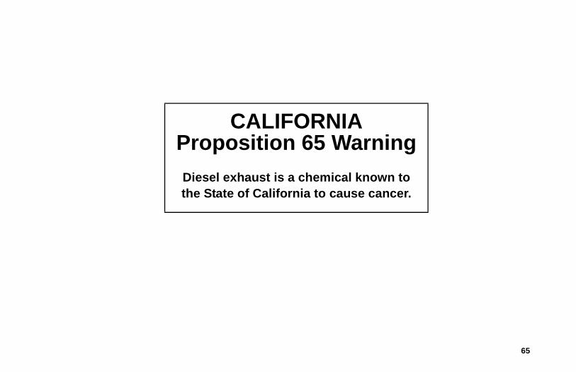
CALIFORNIAProposition 65 WarningDiesel exhaust is a chemical known to the State of California to cause cancer.


Operator’s Manual
Operator’s Manual
Ingersoll Rand’s Climate Solutions sector delivers energy-effi cient HVACR solutions for customers globally. Its world class brands include Thermo King, the leader in transport temperature control and Trane, a provider of energy effi cient heating, ventilating and air conditioning systems, building and contracting services, parts support and advanced controls for commercial buildings and homes.
Ingersoll Rand’s Climate Solutions sector delivers energy-effi cient HVACR solutions for customers globally. Its world class brands include Thermo King, the leader in transport temperature control and Trane, a provider of energy effi cient heating, ventilating and air conditioning systems, building and contracting services, parts support and advanced controls for commercial buildings and homes.
©2013 Ingersoll-Rand Company Printed in U.S.A.
©2013 Ingersoll-Rand Company Printed in U.S.A.
TriPac EVOLUTIONDiesel Particulate Filter
(DPF)
TK 56295-19-OP (Rev. 2, 03/16)
TriPac EVOLUTIONDiesel Particulate Filter
(DPF)
TK 56295-19-OP (Rev. 2, 03/16)