operator’s instruction manual lnx 1000, 1250 & … operator's manu… · operator’s...
TRANSCRIPT

Part Number 44000996 Rev B Page 1 of 22
OPERATOR’S INSTRUCTION MANUAL LNX 1000, 1250 & 1500 Electric Powered Hoists
TO EMPLOYER AND/OR RENTAL AGENCY
It is imperative that this manual be given to the operator of Sky Climber equipment and that they read, fully understand, and follow all instructions
contained herein.
Page 2 of 22
WARNING
Any use of this equipment, other than in strict accordance with these instructions, shall be at the Operator’s risk and may result in serious injury to themselves or others.
TableofContentsHOIST SPECIFICATIONS & CHARACTERISTICS .......................................................................... 4
HOIST OVERVIEW ........................................................................................................................... 5
ELECTRICAL HOISTS ..................................................................................................................... 6
HOIST OPERATION ......................................................................................................................... 6
EMERGENCY OPERATION – POWER FAILURE ......................................................................... 7
EMERGENCY ASCENT – EMERGENCY HANDWHEEL ........................................................... 7
EMERGENCY DESCENT – CONTROLLED DESCENT LEVER ................................................ 9
SUSPENDED ACCESS INSTALLATION ......................................................................................... 9
GUIDELINES ................................................................................................................................. 9
TOP SIDE RIGGING ..................................................................................................................... 9
SECONDARY BRAKE ................................................................................................................ 10
TYPICAL TOP SIDE RIGGING SYSTEMS ................................................................................. 11
FALL ARREST EQUIPMENT ...................................................................................................... 13
PLATFORMS .............................................................................................................................. 13
WELDING .................................................................................................................................... 14
STEEL ROPE REQUIREMENTS ................................................................................................ 14
RIGGING AND REEVING ........................................................................................................... 15
HOIST INSTALLATION & TESTING .............................................................................................. 15
TROUBLESHOOTING .................................................................................................................... 17
MAINTENANCE .............................................................................................................................. 18
SAFETY .......................................................................................................................................... 18
SAFETY DECALS & INSTRUCTIONS ........................................................................................... 19
INSPECTION FREQUENCY & MAINTENANCE ............................................................................ 20
CHECKLISTS ................................................................................................................................. 21
REMEMBER SAFETY IS THE RESPONSIBILITY OF BOTH THE OWNER AND THE OPERATOR.

Page 3 of 22
OPERATOR’S INSTRUCTION MANUAL LNX 1000, 1250 & 1500 Hoists
Welcome to the ever-growing group of Sky Climber Hoist Operators. This manual will guide you through the features and the operation of your Sky Climber Hoist and Secondary Over-Speed Brake.
Sky Climber Hoists and Secondary Over-Speed Brakes are an integral part of a total Suspended Platform System made up of Rigging, Wire Rope, a Power Supply, the Platform, Fall Arrest/Safety Equipment and Accessories. Understanding the complete system, as well as the Hoist operation, will help you in the safe use of a Suspended Platform.
This information is a guide only, and is not a complete list of safety rules, installation or operation instructions.
Sky Climber Hoists, Secondary Over-Speed Brakes and Accessories are designed and manufactured to the highest standards in the industry. It is impossible, however, for Sky Climber, LLC to know, evaluate, and advise in every conceivable way our products are used or serviced and of all possible hazardous consequences.
Therefore, all Operators must satisfy themselves that the procedure they use will not jeopardize their safety, the safety of others, or cause product or component damage.
Sky Climber, LLC reserves the right to continually improve its products. Every effort has been made to make this manual as accurate as possible at the time of publication; however, there may be product changes that are not detailed in this manual.
Sky Climber LLC 1800 Pittsburgh Drive Delaware, Ohio 43015
Telephone – 740-203-3900 Toll Free – 800-255-4629 Facsimile – 740-203-3901
Page 4 of 22
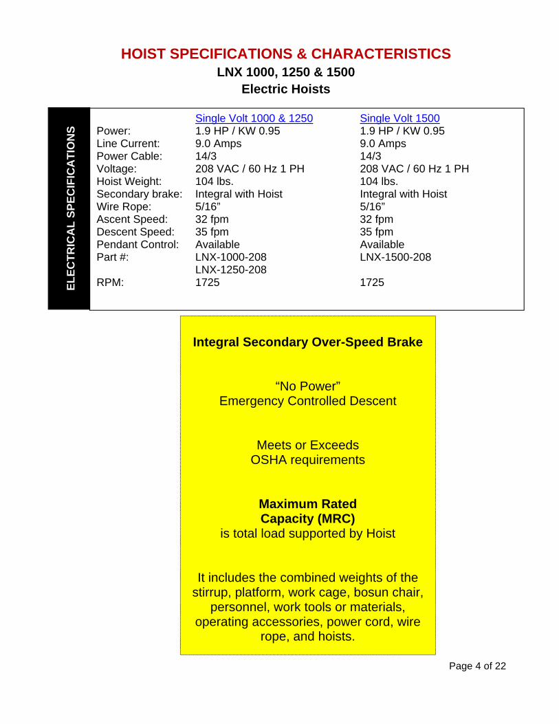
HOIST SPECIFICATIONS & CHARACTERISTICS LNX 1000, 1250 & 1500
Electric Hoists
Integral Secondary Over-Speed Brake
“No Power” Emergency Controlled Descent
Meets or Exceeds OSHA requirements
Maximum Rated Capacity (MRC)
is total load supported by Hoist
It includes the combined weights of the stirrup, platform, work cage, bosun chair,
personnel, work tools or materials, operating accessories, power cord, wire
rope, and hoists.
Single Volt 1000 & 1250 Single Volt 1500 Power: 1.9 HP / KW 0.95 1.9 HP / KW 0.95 Line Current: 9.0 Amps 9.0 Amps Power Cable: 14/3 14/3 Voltage: 208 VAC / 60 Hz 1 PH 208 VAC / 60 Hz 1 PH Hoist Weight: 104 lbs. 104 lbs. Secondary brake: Integral with Hoist Integral with Hoist Wire Rope: 5/16” 5/16” Ascent Speed: 32 fpm 32 fpm Descent Speed: 35 fpm 35 fpm Pendant Control: Available Available Part #: LNX-1000-208 LNX-1500-208 LNX-1250-208 RPM: 1725 1725
EL
EC
TR
ICA
L S
PE
CIF
ICA
TIO
NS
Page 5 of 22
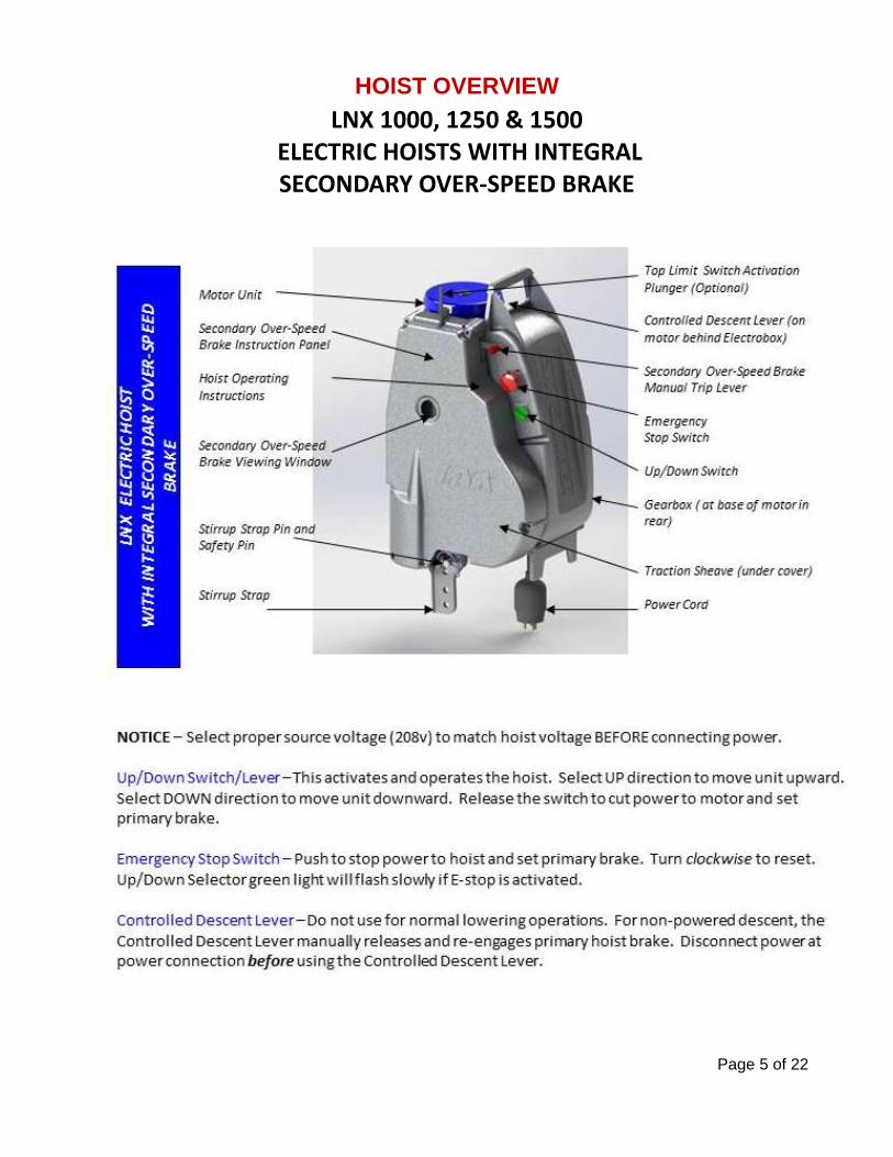
HOIST OVERVIEW
LNX 1000, 1250 & 1500 ELECTRIC HOISTS WITH INTEGRAL SECONDARY OVER‐SPEED BRAKE
Page 6 of 22
ELECTRICAL HOISTS
Secure cord to Platform so cord weight is on Platform and NOT on connection. At end of work shift, disconnect power cord from the main outlet. Protect power cords from rain and water at all times. Ground connector of building receptacle must be grounded.
For 208 Volt applications, use one cord in combination with a yoke to the Hoists. Use a yoke off Platform line with two lengths of 10-3 SOW electric cord. Normally a 250 ft. 600 Volt 10-3 SOW electric cord is used. Use a booster transformer when low voltage is encountered.
Note: If hoist is equipped with low voltage indicator, the main control switch green light will flash rapidly if voltage drops below 193v. If this rapid flashing occurs and remains in this state, install a booster transformer at the source to increase voltage to the hoists.
Electrical Pendant Part # 41021752 – (length).
HOIST OPERATION
The LNX electric hoist is activated by movement of the directional switch/lever.
Hoist is activated by turning directional switch/lever in desired direction of travel -results in engagement of motor and release of brake
Directional switch/lever is spring loaded & returns to OFF when released - results in engagement of brake and disengagement of motor
The hoist is equipped with an Emergency Stop or E-stop Button.
Pressing the RED Emergency Stop Button immediately interrupts power to the hoist motor and engages the brake (causing the hoist to immediately stop)
Turn the red Emergency Stop Button clockwise to reset switch and restore power to hoist
CAUTION: Always allow hoists to come to a full stop before changing
direction of travel. Rapidly changing position of directional switch may result in damage to the electrical components of the hoist.
!
WARNING Do not use an electric hoist in an explosive environment. !

Page 7 of 22
EMERGENCY OPERATION – POWER FAILURE
In the event of loss of power, the hoist may be raised by using the Emergency Hand wheel. The hoist may be lowered using the Controlled Descent Brake Release Lever.
EMERGENCY ASCENT – EMERGENCY HANDWHEEL
If power fails and you desire to raise suspended equipment:
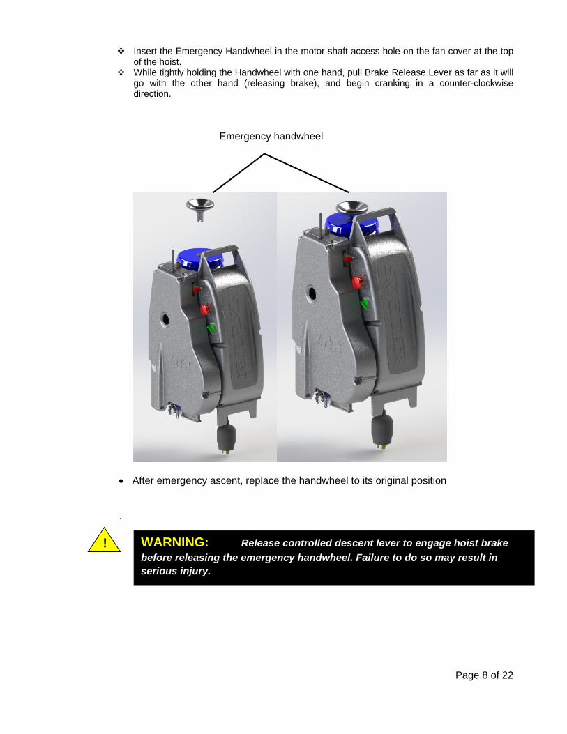
Disconnect the power supply connector plug. Remove the Emergency Handwheel from its position underneath the hoist by unscrewing it
(see figure).
Emergency handwheel
Controlled descent lever
WARNING: Always disconnect power at the power supply connector
plg before using the emergency handwheel or controlled descent lever. Failure to do so may result in serious injury or death.
!
Page 8 of 22
Insert the Emergency Handwheel in the motor shaft access hole on the fan cover at the top of the hoist.
While tightly holding the Handwheel with one hand, pull Brake Release Lever as far as it will go with the other hand (releasing brake), and begin cranking in a counter-clockwise direction.
After emergency ascent, replace the handwheel to its original position .
WARNING: Release controlled descent lever to engage hoist brake
before releasing the emergency handwheel. Failure to do so may result in serious injury.
!
Emergency handwheel

Page 9 of 22
EMERGENCY DESCENT – CONTROLLED DESCENT LEVER
The controlled descent lever is used to lower the hoist in the event of a power interruption. If power fails and you desire to lower the hoist and its load:
Disconnect power supply connector plug from the hoist. Release hoist brake by gently pulling the Controlled Descent Lever toward the fan end of the
motor as far as it will go (see figure).
SUSPENDED ACCESS INSTALLATION GUIDELINES Safety is of the utmost importance when installing and using Suspended Platform equipment. This section covers general guidelines. Follow your Manufacturer’s Instructions for proper equipment assembly. Follow all applicable Federal, State, and Local rules and regulations.
Test your system before going aloft. Continue to check to be sure your system remains safe throughout the entire use on the job. Make certain there are no obstructions to the vertical platform travel.
TOP SIDE RIGGING
All rigging including cornice hooks, parapet clamps, and outrigger beams must be tied back to a structural member with wire rope that is equal or greater in ultimate strength than suspension line.
Tie back must be tied tight to a substantial point that supports at least 4 times the rated Hoist load. Tie back to vent pipes is not acceptable. Tie backs must be straight back and each to a separate anchor point.
Use parapet clamps and cornice hooks only on steel reinforced concrete structures. Do not use parapet clamps on non-reinforced brick, concrete block, or stone because these may fail.
Consult a professional engineer or the building owner to verify parapet construction and strength. Use 3/4 inch plywood under roof rigging to spread load on roof. If parapet is used for support, use
hardwood for load spread. Rolling Roof Rig chocks, jacks or similar devices must be securely in place to prevent any lateral
movement.
WARNING Rigging is the responsibility of the user. Do not attempt to rig a job
unless !
WARNING: Before descending, be sure that the Emergency Handwheel is
removed from hoist. Failure to do so may result in serious injury or death.
CAUTION: Partial release of hoist brake may result in over-heating and
premature brake wear .
!

Page 10 of 22
SECONDARY BRAKE
Failure to do so is in violation of OSHA, and may result in serious injury or death.
The Secondary Over-Speed Brake senses the speed of the wire rope traveling through it. If there is sudden acceleration due to a falling condition, or if the factory pre-set trip speed is exceeded, the brake’s jaws clamp onto the wire rope, arrest any descent, and support the descending load. The wire rope releases only after the Secondary Over-Speed Brake’s load is relieved.
Manual Trip Lever – Pull the red handle downward to lock the jaws onto the wire rope.
Reset – Use the Hoist Directional Switch UP to move Hoist in an upward direction. This will automatically reset the jaws of the Secondary Over-Speed Brake.
WARNING A Secondary Over-Speed Brake safety device must be used at all times with each Sky Climber Hoist. For LNX units, the secondary brake is integral to the hoist. !
Page 11 of 22
TYPICAL TOP SIDE RIGGING SYSTEMS
Counterweighted and Non-Counterweighted
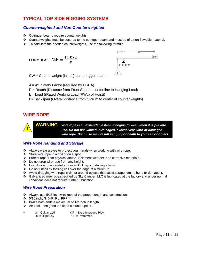
Outrigger beams require counterweights. Counterweights must be secured to the outrigger beam and must be of a non-flowable material. To calculate the needed counterweights, use the following formula:
FORMULA:
CW = Counterweight (in lbs.) per outrigger beam 4 = 4:1 Safety Factor (required by OSHA) R = Reach (Distance from Front Support center line to Hanging Load) L = Load ((Rated Working Load (RWL) of Hoist)) B= Backspan (Overall distance from fulcrum to center of counterweights)
WIRE ROPE
Wire Rope Handling and Storage
Always wear gloves to protect your hands when working with wire rope. Store wire rope in a coil or on a spool. Protect rope from physical abuse, inclement weather, and corrosive materials. Do not drop wire rope from any height. Uncoil wire rope carefully to avoid kinking or inducing a twist. Do not uncoil by tossing coil over the edge of a structure. Avoid dragging wire rope in dirt or around objects that could scrape, crush, bend or damage it. Galvanized wire rope specified by Sky Climber, LLC is lubricated at the factory and under normal
conditions does not require further lubrication.
Wire Rope Preparation
Always use 5/16 inch wire rope of the proper length and construction. 5/16 inch, G, XIP, RL, PRF ** Braze both ends a maximum of 1/2 inch in length. Air cool, then grind the tip to a blunted point.
** G = Galvanized XIP = Extra Improved Plow RL = Right Lay PRF = Preformed
! WARNING Wire rope is an expendable item. It begins to wear when it is put into
use. Do not use kinked, bird-caged, excessively worn or damaged wire rope. Such use may result in injury or death to yourself or others.
Page 12 of 22
Wire Rope Rigging
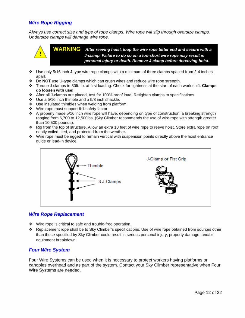
Always use correct size and type of rope clamps. Wire rope will slip through oversize clamps. Undersize clamps will damage wire rope.
Use only 5/16 inch J-type wire rope clamps with a minimum of three clamps spaced from 2-4 inches apart.
Do NOT use U-type clamps which can crush wires and reduce wire rope strength. Torque J-clamps to 30ft.-lb. at first loading. Check for tightness at the start of each work shift. Clamps
do loosen with use! After all J-clamps are placed, test for 100% proof load. Retighten clamps to specifications. Use a 5/16 inch thimble and a 5/8 inch shackle. Use insulated thimbles when welding from platform. Wire rope must support 6:1 safety factor. A properly made 5/16 inch wire rope will have, depending on type of construction, a breaking strength
ranging from 6,700 to 12,500lbs. (Sky Climber recommends the use of wire rope with strength greater than 10,500 pounds).
Rig from the top of structure. Allow an extra 10 feet of wire rope to reeve hoist. Store extra rope on roof neatly coiled, tied, and protected from the weather.
Wire rope must be rigged to remain vertical with suspension points directly above the hoist entrance guide or lead-in device.
Wire Rope Replacement
Wire rope is critical to safe and trouble-free operation. Replacement rope shall be to Sky Climber’s specifications. Use of wire rope obtained from sources other
than those specified by Sky Climber could result in serious personal injury, property damage, and/or equipment breakdown.
Four Wire System
Four Wire Systems can be used when it is necessary to protect workers having platforms or canopies overhead and as part of the system. Contact your Sky Climber representative when Four Wire Systems are needed.
! WARNING After reeving hoist, loop the wire rope bitter end and secure with a
J-clamp. Failure to do so on a too-short wire rope may result in personal injury or death. Remove J-clamp before dereeving hoist.

Page 13 of 22
FALL ARREST EQUIPMENT OSHA requires an independent life line for each person going aloft. A safety harness must be worn by each worker and be attached by a lanyard and rope grab to an independent life line while a worker is on the platform. Life Lines
Only one person may be attached to a life line. The life line must be:
Sized for and compatible with the rope grab (e.g., 5/8 inch line for a 5/8 inch rope grab). Certified minimum breaking strength of 5,000 lbs. Seized or whipped at the ends. Tied off to a separate attachment point different from the wire rope attachment point capable of
supporting 5,000 lbs. Do not allow life line to come in contact with rough or sharp edges. Life line must extend to the ground or the next lower safe surface.
Rope Grab
Inspect all parts of the rope grab prior to each use. Perform a documented rope grab inspection at least twice a year.
The rope grab should always be mounted on the life line as far above the operator as possible.
Body Harness
Harnesses must comply with the latest edition of ANSI A10.14.
Position a body harness D-ring in the center of the back rib cage. Follow the safety equipment manufacturer’s instructions.
Lanyards
Lanyards must meet or exceed OSHA standards.
Lanyards must be 4 feet long (or less with double snap locks). Minimum tensile strength is 5,000 lbs.
PLATFORMS Follow the platform load specification. Check stirrup bolts daily for soundness and tightness. Use toeboards, handrails and mid-rails on all open sides. Acids can destroy aluminum platforms. Replace platform immediately if exposed to acids or corrosive
materials. Operate platform in level position only. Work from deck of platform only. Do not stand on guardrails, toeboards, platform/work cage supported
objects or lean out from ends of the platform. Do not use ladders etc. to get at higher elevations. Do not bridge from one platform to another, nor to any structure or other equipment. Do not horizontally transfer a work platform while it is suspended in the air. Perform all transfer
operations ONLY with the platform resting on a safe surface. Bosun chairs should carry only the operator. Do not hang loads from the seat or attach any device or
support to seat or seat back.

Page 14 of 22
WELDING
Use the following precautions when welding to prevent the possibility of electric shock to personnel and/or the possibility of welding current passing through the wire rope. Attach each wire rope to its suspension point with a suitable insulated thimble. Insulate extra rope stored
on the roof to prevent grounding, or terminate the suspension rope at the insulated thimble. Cover the supporting wire rope with insulating material above and below the Sky Climber® Hoist.
Use a length of split rubber tube taped in place around the cable as follows: Extend above the top of the hoist for 4 to 5 feet (more if required by local codes). Extend below the Sky Climber® Hoist, far enough to insulate the tail line from the
platform. Guide and/or retain the portion of the tail line below the platform so that it does not become grounded.
Cover each Sky Climber Hoist, Sky Lock Brake, and Wire Winder with protective covers made from insulating material.
Connect a grounding conductor from the platform to the work piece. The size of this conductor must be equal to or greater than the size of the stinger lead.
STEEL ROPE REQUIREMENTS
Recommended Wire Rope – LNX 1000, 1250 & 1500
Sky Climber has found the 5/16”, (8.0 mm) 5-strand wire rope to be the most effective for trouble-free operation. Please use only that rope which is recommended by the manufacturer.
Product
5/16” (8.0 mm) 5 x 26 WS, PFC, G, XIP, RRL, performed, break strength of 11,585 lbs.
Compliance
Use only the specified wire rope in the LNX1000, 1250 &1500 Hoist. If further information is needed, please contact Sky Climber at 770/939-7705 or 800/255-4629. All wire rope used must conform to Federal Specifications RR-W-410P Type 1, General Purpose, Class 2. The supplier should provide a Certification of Breaking Strength proving a minimum strength. This rope is resistant to abrasion and crushing with medium fatigue resistance.
WS Warrington Seal PFC Polypropylene Fiber Core G Galvanized XIP Extra Improved Plow RRL Regular Right Lay Steel
NOTE: This must be a secondary conductor and must not be in series with the primary conductor between the welder and the work piece.
Page 15 of 22
Tipping and Braising
Braze a wire rope tip by applying braze to approximately 1/2 inch of tip (do not exceed 3/4 inch) and let it glow to all of the individual wires. Let the rope AIR COOL. Air cooling is very important. Then grind the tip to a taper, but not a point. Tip should resemble a pencil with the lead broken off.
How to Check for Proper Wrapping
Cut 50 to 100 feet from your new spool of specified wire rope. Braze both ends and run it through a hoist 10 times (no load needed). Check if the strands are separating above or below the hoist. If they DO appear to be opening, then the strands are improperly wrapped and will result in hoist jamming. Return the spool to your supplier.
RIGGING AND REEVING At the job site, rig from the top down. Lower wire rope until you have about 10 feet of rope on the ground (hoist is not yet reeved). Complete the tie point with 3 fist grips (or J-clamps), thimble and shackle (torque fist grips to manufacturer’s recommendations). Store the extra wire rope in a coil on the roof.
HOIST INSTALLATION & TESTING
Suspended Platform Assembly
Follow manufacturer’s instructions. If used, install an electric yoke on the platform (wrapped around center guardrails) to provide power to
each hoist. Secure source power line(s) to Suspended Platform by strain relief(s) or other load-bearing device. Plug
the power line into yoke (if used). Allow sufficient power line length to permit free platform travel without undue strain to the power line and
platform.
Hoist Installation
Place hoist next to Suspended Platform Stirrup. Connect Power. Thread wire rope through hoist. Keep hands clear of pinch point where wire rope enters hoist.
Feed brazed and pointed end of wire rope into hoist entrance guide until rope stops. To start self-reeving, move Directional Switch to UP direction. Wire rope must be free to travel without interference. Exit guide must be clear. Wire rope must run freely away from the hoist. Guide hoist as it climbs up to the stirrup level.
NOTE: Adjust wire rope length as you change elevations. Reeve the hoist, form a 360° loop in the tail end and retain with a fist grip. Before dereeving the hoist, remove the fist grip.

Page 16 of 22
Attach hoist to Suspended Platform Stirrup. Release hoist stirrup strap by removing safety pin, removing latch pin and allowing strap to
rotate into a vertical position. Replace latch pin and safety pin. Insert hoist stirrup strap into platform stirrup recess. Use either Grade 5 nuts/bolts or shoulder bolts and nuts provided by manufacturer. Tighten nuts securely. Make sure wire rope exits outward, away from platform’s work area.
Secure Wire Rope End. Limit wire rope bitter end to a few feet. Store excess wire rope at top on suspension end.
Test Hoist Load. Place load equal to weight of workers, tools and materials on one end of the platform. Have co-
worker check rigging for slippage/malfunction during the test. Inspect all rigging/platform connections. Tighten or adjust as needed. Select Hoist Directional Switch UP direction to raise the platform 6 inches off surface. Pull the red lever to actuate the integral Secondary Over-Speed Brake. Select Hoist Directional Switch DOWN direction. System should not descend.
Select Hoist Directional Switch in the UP direction and raise the platform one inch to relieve reset the secondary over-speed brake..
Repeat procedure twice. Repeat the same hoist load test procedure at the other end of the platform. If hoist or secondary over-speed brake fails test, return failed unit to Factory Authorized Service
Center.
Test Emergency Stop Button. Select Hoist Directional Switch in the UP direction to raise platform 6 inches. While ascending,
press the Emergency Stop Button. Power should stop to hoist and primary brake should engage. Turn Emergency Stop Button Switch clockwise to reset. Repeat test. If Emergency Stop fails, return hoist to Factory Authorized Service Center.
Test Controlled Descent System.
Partial Hoist Brake Release may result in overheating and premature wear. Raise suspended equipment 2 feet off the ground. Use the Controlled Descent Lever to manually release the primary hoist brake. For non-powered descent, pull the Controlled Lowering Lever as far as it will go toward the end
of the motor. The hoist should lower at about 35 feet per minute.
Do NOT use any equipment that has failed testing!
! WARNING Serious injury or property damage may result from falling
objects during hoist load test. Be alert and prepared to quickly move from the likely impact zone.
Page 17 of 22
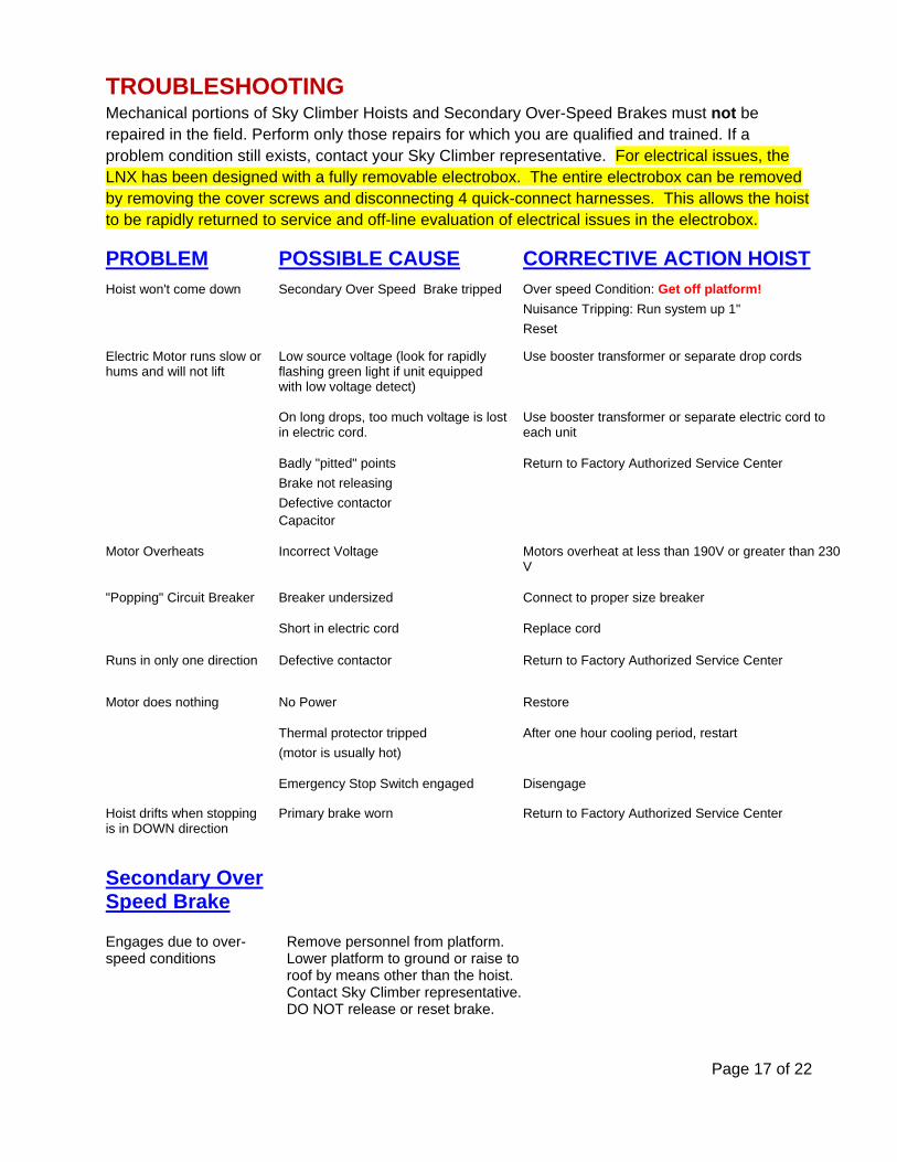
TROUBLESHOOTING Mechanical portions of Sky Climber Hoists and Secondary Over-Speed Brakes must not be repaired in the field. Perform only those repairs for which you are qualified and trained. If a problem condition still exists, contact your Sky Climber representative. For electrical issues, the LNX has been designed with a fully removable electrobox. The entire electrobox can be removed by removing the cover screws and disconnecting 4 quick-connect harnesses. This allows the hoist to be rapidly returned to service and off-line evaluation of electrical issues in the electrobox.
PROBLEM POSSIBLE CAUSE CORRECTIVE ACTION HOISTHoist won't come down Secondary Over Speed Brake tripped Over speed Condition: Get off platform!
Nuisance Tripping: Run system up 1"
Reset
Electric Motor runs slow or hums and will not lift
Low source voltage (look for rapidly flashing green light if unit equipped with low voltage detect)
Use booster transformer or separate drop cords
On long drops, too much voltage is lost in electric cord.
Use booster transformer or separate electric cord to each unit
Badly "pitted" points Return to Factory Authorized Service Center
Brake not releasing
Defective contactor Capacitor
Motor Overheats Incorrect Voltage Motors overheat at less than 190V or greater than 230 V
"Popping" Circuit Breaker Breaker undersized Connect to proper size breaker
Short in electric cord Replace cord
Runs in only one direction Defective contactor Return to Factory Authorized Service Center
Motor does nothing No Power Restore
Thermal protector tripped After one hour cooling period, restart
(motor is usually hot)
Emergency Stop Switch engaged Disengage
Hoist drifts when stopping is in DOWN direction
Primary brake worn Return to Factory Authorized Service Center
Secondary Over Speed Brake
Engages due to over-speed conditions
Remove personnel from platform. Lower platform to ground or raise to roof by means other than the hoist. Contact Sky Climber representative. DO NOT release or reset brake.

Page 18 of 22
MAINTENANCE Return Sky Climber Hoists as indicated to Factory Authorized Service Center for maintenance. Sky Climber Hoists are lubricated for normal usage and life. If an oil leak is seen, return hoist to
Factory Authorized Service Center. Keep rope housing drain holes at bottom of hoist open.
FLUSHING: Keep Hoist and Secondary Over Speed Brake free of contaminants. Perform the following steps when using equipment in a contaminated environment using gunite, hydroblasting, or sand-blasting:
Lower equipment to ground. De-reeve the hoist. Disconnect power. Hold hose at wire rope entrance, flush Sky Lock with fresh water. Repeat flushing on the Hoist while running hoist in the UP and DOWN direction until no further
contaminants exit from drain holes. Reeve the hoist and continue operations.
SAFETY
Accidents will be prevented if you follow the instructions in this manual. Once the equipment leaves Sky Climber’s control, the Operator is responsible for the safe use, operation, and maintenance.
Safety Prevents Accidents
Know and understand the operation of this equipment. All Federal, State, and local codes and regulations that apply to this equipment and its safe use must be
followed. Do not alter any Sky Climber Hoists, Secondary Over Speed Brake or Accessories. Use only Sky
Climber original parts in your Sky Climber equipment. Thoroughly inspect all equipment before use. Do not use any equipment that has any apparent
difficulty. Wear hard hats at all times when servicing, erecting, disassembling, or using equipment. Secure suspended platform to building face/structure while at workstation. Disconnect platform from
building face (other than platforms using continuous engagement) before it is moved. Provide protection for workers from falling objects both above and below the equipment. Keep all persons from beneath suspended equipment. Never work alone on a suspended platform, and ensure help is available in an emergency. Do not overload the equipment or exceed the maximum rated capacity as noted in this manual. Do not wear loose clothing while operating this equipment.
SAFETY IS IMPORTANT. Use Common Sense … Do NOT Take Chances!
Page 19 of 22
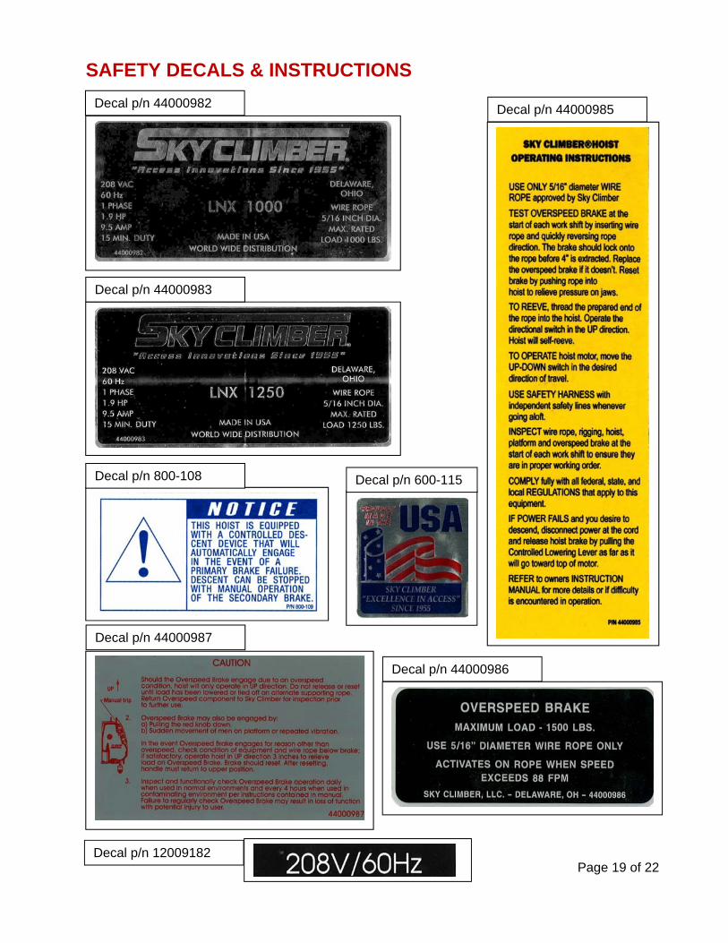
SAFETY DECALS & INSTRUCTIONS
Decal p/n 44000982 Decal p/n 44000985
Decal p/n 44000983
Decal p/n 800-108 Decal p/n 600-115
Decal p/n 44000987
Decal p/n 44000986
Decal p/n 12009182

Page 20 of 22
INSPECTION FREQUENCY & MAINTENANCE
Field Inspection
Inspection must be performed by a designated qualified person or operator.
Inspection Frequency
Inspect ALL equipment as follows:
When the system is reeved. At the start of each work shift. At least every 4 hours in abrasive, caustic, or adhesive conditions. At least every 2 hours in freezing conditions.
Factory Inspection, Maintenance, and Testing
Return Sky Climber Hoists and Secondary Over-Speed Brakes to a Factory Authorized Service Center for inspection, maintenance, and testing as follows:
Every 12 months in non-contaminated and non-freezing environments. Every 6 months in contaminated or freezing environments. After every job for gunite, hydroblasting, or sandblasting.
! WARNING Failure to comply with Periodic Inspection and Factory
Authorized Service Maintenance may result in a malfunction and/or in serious personal injury, property damage, or death.

Page 21 of 22
CHECKLISTS CHECK DAILY or before the start of each shift:
Cornice Hook Substantial structure for hook and tieback point Tieback at proper angle Check fist grip torque (5/16” – 30 ft. lbs.; 3/8” – 45 ft. lbs.) Bearing block in place Warning and rating labels in place and legible Capacity equal to or greater than hoist rated working load Spacing of hooks equal to hoist spacing
Parapet Clamp Substantial structure for clamp and tieback Wall surfaces parallel (vertical) Tieback at proper angle Check fist grip torque (5/16” – 30 ft. lbs.; 3/8” – 45 ft. lbs.) Warning and rating labels in place and legible Capacity equal to or greater than hoist rated working load Spacing of clamps equal to hoist spacing
Rolling Roof Rigs Tieback at proper angle to substantial structure Check fist grip torque (5/16” – 30 ft. lbs.; 3/8” – 45 ft. lbs.) Load on jacks – not casters All hardware in place and properly torque Warning and Rating labels in place and legible Counterweights – correct amount, properly attached Beam reach limit not exceeded for hoist rating Spacing of beams equal to hoist spacing
Tank Top Tieback to substantial structure Check fist grip torque (5/16” – 30 ft. lbs.; 3/8” – 45 ft. lbs.) Make sure roller is seated properly Warning and Rating labels in place and legible Make sure roller rating is equal to or greater than hoist capacity
Ring Girder Roller Tieback to substantial structure Check fist grip torque (5/16” – 30 ft. lbs.; 3/8” – 45 ft. lbs.) Make sure roller is seated properly Warning and Rating labels in place and legible Make sure roller rating is equal to or greater than hoist capacity
Rigging Slings Make sure sling is attached to a substantial structure (4:1 Safety Factor) Check fist grip torque (5/16” – 30 ft. lbs.; 3/8” – 45 ft. lbs.) Make sure rope is protected at chafing points Make sure rope is protected at break points

Page 22 of 22
CHECKLISTS (Continued)
CHECK DAILY or before the start of each shift:
Permanent Davits – Daily Check Make sure davit has been inspected and tested prior to use Make sure davit is installed per manufacturer’s instructions Make sure capacity is equal to or greater than hoist capacity Check fist grip torque (if used)
Counterweights – Daily Check Must be designed for use as counterweight Make sure they are securely attached to beam Make sure they are made from a non-flammable material Make sure they are labeled individually. Sky Climber counterweights are 50 lbs.
Ascertain that:
Instructions are kept with the unit at all times. Additional copies are available – contact Sky Climber.
All Warning and Rating labels are in place, legible, and have been read.
Hoist Drain Holes on the bottom are open. Fasteners checked.
Suspended Platform Hoist is connected to proper power source.
Minimum of 3 J-Clamps are used and are tight. (4 J-Clamps are required for round thimbles).
Cornice Hook, Parapet Clamps or Outriggers, and similar rigging are secured and tied back. Chokers or
similar devices are securely in place. Tie backs are tight and straight back.
Counterweights are non-flowable type, secure, and correct amount.
Roof rigging load is spread using 3/4 inch plywood. Hardwood used for Load Spreader with Parapet.
Wire rope inspected and is not kinked, bird-caged, or otherwise damaged.
The wire rope bitter end is looped and secured with a J-Clamp.
Secondary Over-Speed Brake, Hoist Load, Controlled Descent, and Emergency Stop tests performed
and acceptable.
!
WARNING Do NOT use Sky Climber Hoists, Secondary Over-Speed
Brakes, or any equipment that is damaged or worn beyond normal tolerances.