operator’s manual - dickey-john · operator’s manual ... com1 pin assignment details ... 2....
TRANSCRIPT
OPERATOR’S MANUAL
Safety Notices ..................................................................................................... 1
Introduction ......................................................................................................... 3Sample Testing ................................................................................................................. 3Printer Connection (Optional) ........................................................................................... 4Computer Interface .......................................................................................................... 4Features ............................................................................................................................ 4GAC® 2100 G/GI Specifications ...................................................................................... 5
Installation and Setup ......................................................................................... 7Unit Positioning ................................................................................................................ 7Disengaging Shipping Brace ............................................................................................ 8Connecting AC Power ....................................................................................................... 9Removing Drawer Bottom (Optional) ............................................................................... 9Using Language Modes .................................................................................................. 10Changing Access Codes ................................................................................................ 10Using the Communication Ports .................................................................................... 10
Start-Up & Familiarization ................................................................................ 11Startup Procedure ........................................................................................................... 11Display Screen ............................................................................................................... 12Adjusting Screen Contrast .............................................................................................. 12Defining Keyboard Key Functions .................................................................................. 12Menu Screens ................................................................................................................. 15Alarm ............................................................................................................................... 15
Measuring Moisture .......................................................................................... 17Preparing to Test Moisture ............................................................................................. 17Measuring Moisture (Basic Method) .............................................................................. 18Using Grain Sample ID Numbers ................................................................................... 20Entering Numbers & Alpha Characters .......................................................................... 20Using ID Options ............................................................................................................ 21Viewing the Next Page ................................................................................................... 22
Grain Selection .................................................................................................. 23Using Select Grain Menu ............................................................................................... 23Calibrating Procedures .................................................................................................. 24Viewing Calibration Data (1 Key) ................................................................................... 24Entering/Changing Calibration Values (2 Key) .............................................................. 26Printing Calibration Grain List (3 Key) ............................................................................ 28Obtaining Basic Calibration Data (4 Key) ...................................................................... 28
Establishing Parameters ................................................................................. 31Clearing the Cycle Counter (1 Key) ............................................................................... 31Choosing ID Options (2 Key) ......................................................................................... 32Configuring Output Options (3 Key) ............................................................................... 33Changing the Access Code (4 Key) ............................................................................... 36Changing Date, Time and Date Format (5 Key) ............................................................. 37Changing the Labels (6 Key) ......................................................................................... 39Setting Communications Port Parameters (7 Key) ........................................................ 40Using the Service Menu (8 Key) .................................................................................... 47
GAC2100 G/GI Grain Analysis Computer11001-1381-200605
I
OPERATOR’S MANUAL
Testing Unit Performance ................................................................................ 49Nonactive Keys ............................................................................................................... 49Viewing COM1 Port (2 Key) ........................................................................................... 50Viewing Com2 Transmit Port (3 Key) ............................................................................ 50Viewing Display Characters (5 Key) .............................................................................. 51Viewing Diagnostic Mode (6 Key) .................................................................................. 52Using Test Network Mode (7 Key) .................................................................................. 54Viewing/Printing Parameters (8 key) .............................................................................. 56
Operator Maintenance ..................................................................................... 59Cell Cleaning - Daily ...................................................................................................... 59Fuse Replacement ........................................................................................................ 59
Error Codes ....................................................................................................... 61
Appendix A - Communication Ports ............................................................... 65COM1 Port Options ........................................................................................................ 65COM1 Pin Assignment Details ...................................................................................... 65COM2 Port Options ........................................................................................................ 67COM2 Pin Assignment Details ....................................................................................... 67
GAC2100 G/GI Grain Analysis Computer11001-1381-200605
II

OPERATOR’S MANUAL
Safety Notices ..................................................................................................... 1
Introduction ......................................................................................................... 3Sample Testing ................................................................................................................. 3Printer Connection (Optional) ........................................................................................... 4Computer Interface .......................................................................................................... 4Features ............................................................................................................................ 4GAC® 2100 G/GI Specifications ...................................................................................... 5
Installation and Setup ......................................................................................... 7Unit Positioning ................................................................................................................ 7Disengaging Shipping Brace ............................................................................................ 8Connecting AC Power ....................................................................................................... 9Removing Drawer Bottom (Optional) ............................................................................... 9Using Language Modes .................................................................................................. 10Changing Access Codes ................................................................................................ 10Using the Communication Ports .................................................................................... 10
Start-Up & Familiarization ................................................................................ 11Startup Procedure ........................................................................................................... 11Display Screen ............................................................................................................... 12Adjusting Screen Contrast .............................................................................................. 12Defining Keyboard Key Functions .................................................................................. 12Menu Screens ................................................................................................................. 15Alarm ............................................................................................................................... 15
Measuring Moisture .......................................................................................... 17Preparing to Test Moisture ............................................................................................. 17Measuring Moisture (Basic Method) .............................................................................. 18Using Grain Sample ID Numbers ................................................................................... 20Entering Numbers & Alpha Characters .......................................................................... 20Using ID Options ............................................................................................................ 21Viewing the Next Page ................................................................................................... 22
Grain Selection .................................................................................................. 23Using Select Grain Menu ............................................................................................... 23Calibrating Procedures .................................................................................................. 24Viewing Calibration Data (1 Key) ................................................................................... 24Entering/Changing Calibration Values (2 Key) .............................................................. 26Printing Calibration Grain List (3 Key) ............................................................................ 28Obtaining Basic Calibration Data (4 Key) ...................................................................... 28
Establishing Parameters ................................................................................. 31Clearing the Cycle Counter (1 Key) ............................................................................... 31Choosing ID Options (2 Key) ......................................................................................... 32Configuring Output Options (3 Key) ............................................................................... 33Changing the Access Code (4 Key) ............................................................................... 36Changing Date, Time and Date Format (5 Key) ............................................................. 37Changing the Labels (6 Key) ......................................................................................... 39Setting Communications Port Parameters (7 Key) ........................................................ 40Using the Service Menu (8 Key) .................................................................................... 47
GAC2100 G/GI Grain Analysis Computer11001-1381-200605
I

OPERATOR’S MANUAL
Testing Unit Performance ................................................................................ 49Nonactive Keys ............................................................................................................... 49Viewing COM1 Port (2 Key) ........................................................................................... 50Viewing Com2 Transmit Port (3 Key) ............................................................................ 50Viewing Display Characters (5 Key) .............................................................................. 51Viewing Diagnostic Mode (6 Key) .................................................................................. 52Using Test Network Mode (7 Key) .................................................................................. 54Viewing/Printing Parameters (8 key) .............................................................................. 56
Operator Maintenance ..................................................................................... 59Cell Cleaning - Daily ...................................................................................................... 59Fuse Replacement ........................................................................................................ 59
Error Codes ....................................................................................................... 61
Appendix A - Communication Ports ............................................................... 65COM1 Port Options ........................................................................................................ 65COM1 Pin Assignment Details ...................................................................................... 65COM2 Port Options ........................................................................................................ 67COM2 Pin Assignment Details ....................................................................................... 67
GAC2100 G/GI Grain Analysis Computer11001-1381-200605
II

OPERATOR’S MANUAL
SAFETY NOTICES
Safety notices are one of the primary ways to call attention to potential hazards.
This Safety Alert Symbol identifies important safety messages in this manual. When you see this symbol, carefully read the message that follows. Be alert to the possibility of personal injury or death.
Use of the word WARNING indicates a potentially hazardous situation which, if not avoided, could result in death or serious injury.
Use of the word CAUTION with the Safety Alert Symbol indicates a potentially hazardous situation which, if not avoided, may result in minor or moderate injury.
Use of the word CAUTION without the safety alert symbol indicates a potentially hazardous situation which, if not avoided, may result in equipment damage.
GAC® 2100 G/GI Grain Analysis Computer11001-1381-200605
SAFETY NOTICES / 1

OPERATOR’S MANUAL
GAC2100 G/GI Grain Analysis Computer11001-1381-200605
2 / SAFETY NOTICES
OPERATOR’S MANUAL
INTRODUCTION
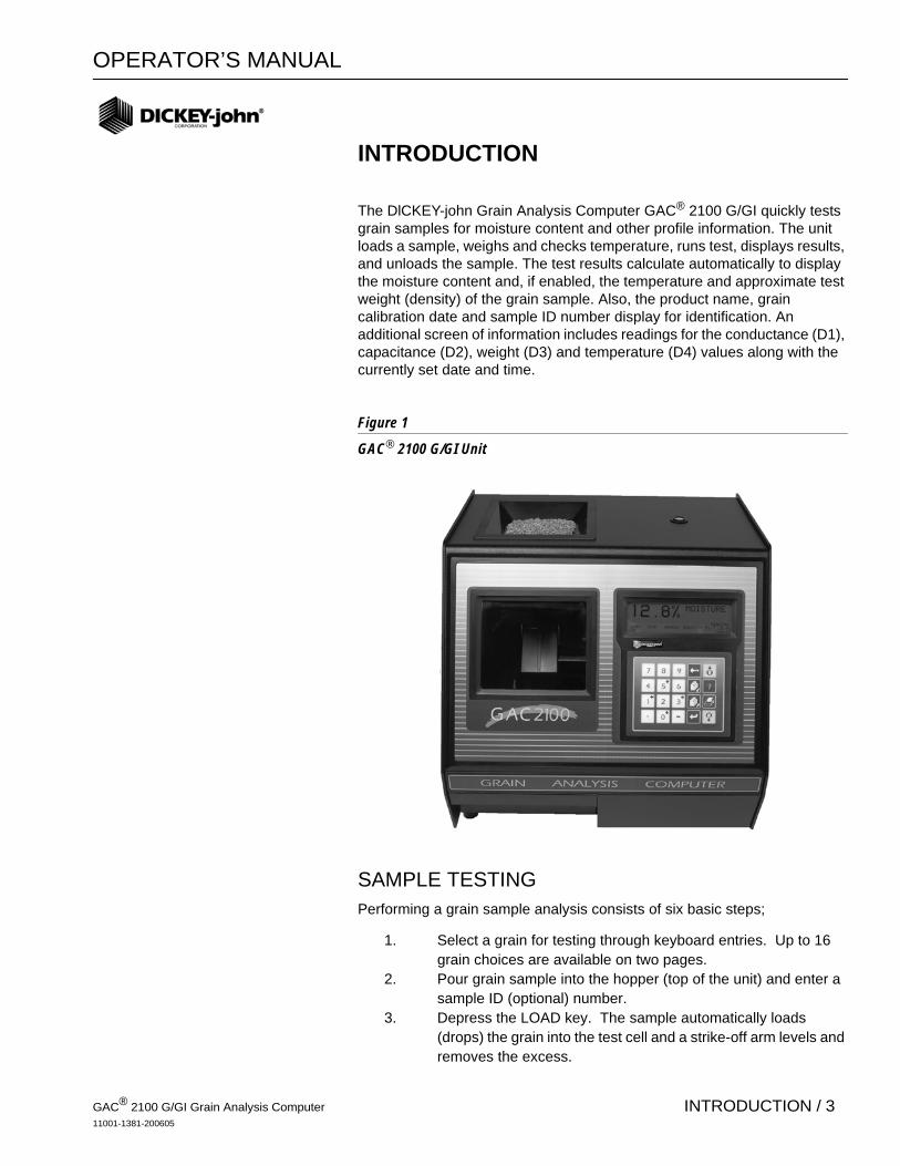
The DlCKEY-john Grain Analysis Computer GAC® 2100 G/GI quickly tests grain samples for moisture content and other profile information. The unit loads a sample, weighs and checks temperature, runs test, displays results, and unloads the sample. The test results calculate automatically to display the moisture content and, if enabled, the temperature and approximate test weight (density) of the grain sample. Also, the product name, grain calibration date and sample ID number display for identification. An additional screen of information includes readings for the conductance (D1), capacitance (D2), weight (D3) and temperature (D4) values along with the currently set date and time.
Figure 1
GAC® 2100 G/GI Unit
SAMPLE TESTINGPerforming a grain sample analysis consists of six basic steps;
1. Select a grain for testing through keyboard entries. Up to 16 grain choices are available on two pages.
2. Pour grain sample into the hopper (top of the unit) and enter a sample ID (optional) number.
3. Depress the LOAD key. The sample automatically loads (drops) the grain into the test cell and a strike-off arm levels and removes the excess.
GAC® 2100 G/GI Grain Analysis Computer11001-1381-200605
INTRODUCTION / 3

OPERATOR’S MANUAL
4. Wait briefly for the test results to process. The moisture reading and grain temperature display.
5. Print out a hard copy of the test results. With an optional printer connected, the date and time with sample identification number and all test information prints out. By depressing the PRINT key, additional copies can be printed.
6. Press the Unload key to empty the test cell contents. The test cell rotates 180° (inverts) to dump the grain into a sample drawer or into a larger container below the counter top. After the cell returns to the upright position, the unit is ready for the next test sample.
PRINTER CONNECTION (OPTIONAL)An optional printer connects to the GAC® 2100 G/GI to print out test data results. The printout may include the facility name and address, current date and time, sample ID number, product name, grain calibration date, percent moisture, grain temperature, unit serial number and the D1 through D4 values. The data can automatically print at the end of each measurement cycle or be manually initiated by pressing the Print key.
COMPUTER INTERFACE The GAC® 2100 G/GI can output to a personal computer (PC) using the COM1 or COM2 ports. When using the COM2 port, a null cable or null adaptor must be used. A null adaptor is available from DICKEY-john.
FEATURESFeatures of the GAC® 2100 G/GI include:
• Memory for up to 16 different grain calibrations. • Keyboard entry for updating grain calibrations as revisions become
necessary.• Alpha/numeric sample identification numbers with automatic
sequential numbering for record keeping purposes. • Automatic ranging by switching to predetermined calibrations when
moisture is above or below normal limits. • Two serial output ports available for printer and/or external computer. • Self-check mode to assure proper continual operation. • Error messages display when out-of-limits moisture, grain weight or
grain temperature occur.• Help screens to assist operator’s questions.
Print key
Unload key
GAC2100 G/GI Grain Analysis Computer11001-1381-200605
4 / INTRODUCTION

OPERATOR’S MANUAL
Figure 2
GAC® 2100 G/GI Dimensions
GAC® 2100 G/GI SPECIFICATIONS • Supply Voltage and Frequency Limits: 85 Vac to 264 Vac 48-440 Hz
at 1 Amp Max. • Operating Temperature Range: 5° C (41° F) to 45° C (113° F). If the
unit temperature range is exceeded, an ERROR message displays. • Grain Temperature Range: 0° C (32° F) to 50° C (122° F). If the grain
temperature range is exceeded, an ERROR message displays. • Unit Temperature and Grain Temperature Difference Limit: The
maximum allowable temperature differential between empty cell and grain under test is 20° C (36° F). If exceeded, an ERROR message displays.
• Classes/Types of Grain or Seed: Refer to the latest Calibration Bulletin.
• Weight: 11.8 kg (26 lbs) – Shipping Weight: 15.0 kg (33 lbs)
GAC2100 G/GI Grain Analysis Computer11001-1381-200605
INTRODUCTION / 5

OPERATOR’S MANUAL
GAC2100 G/GI Grain Analysis Computer11001-1381-200605
6 / INTRODUCTION

OPERATOR’S MANUAL
INSTALLATION AND SETUP
Before shipping, the GAC® 2100 G/GI is inspected and tested for mechanical and electrical defects. After unpacking, visually inspect for damage occurring during transit. Save all packing materials until inspection is complete. If damage is found, file a claim with the carrier immediately. and notify your DICKEY-john sales representative.
UNIT POSITIONING Choose a clean environment for the GAC® 2100 G/GI that is protected from rapid changes in ambient temperature. Avoid a hazardous (classified) location as defined in Article 500 of the NFPA Handbook of the National Electrical Code.
Use the self-contained level on the panel top to position the GAC® 2100 G/GI on a flat level or nearly level surface (See Figure 2). Adjust the four rubber foot pads to level and stabilize the unit (See Figure 3). When moving the unit to a different location, re-leveling may be necessary. After adjustment is complete, all four leveling foot pads should be set to the lowest level possible with one pad fully seated against the bottom panel. This assures minimum height above the counter top.
Figure 3Leveling Unit with Rubber Foot Pads
To adjust a foot pad height, use a flat wrench to unlock the upper nut from the bottom panel of the selected foot pad. Then, adjust the height as required.
After adjusting, use a Phillips screwdriver in the center of the footpad to hold the screw from turning and tighten the upper nut against the bottom panel of the unit. Ensure the lower nut remains tight against the footpad.
Rubber Foot Pads
Use a Phillips screwdriver in center of pad to change height and to hold the screw from turning while tightening nuts.
2. After adjustment, retighten nut up against bottom panel.
1. Use wrench to loosen the upper nut and then adjust height.
3. Ensure bottom nut is locked down against rubber foot pad.
GAC® 2100 G/GI Grain Analysis Computer11001-1381-200605
INSTALLATION AND SETUP / 7
OPERATOR’S MANUAL
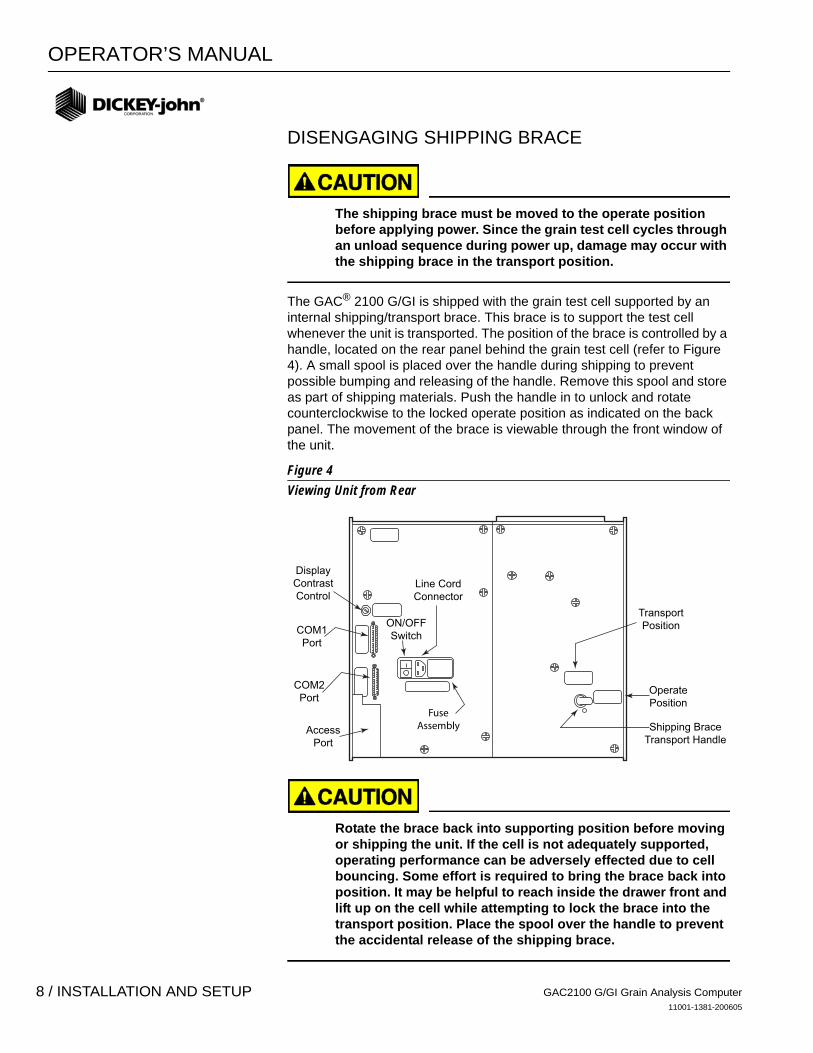
DISENGAGING SHIPPING BRACE
The shipping brace must be moved to the operate position before applying power. Since the grain test cell cycles through an unload sequence during power up, damage may occur with the shipping brace in the transport position.
The GAC® 2100 G/GI is shipped with the grain test cell supported by an internal shipping/transport brace. This brace is to support the test cell whenever the unit is transported. The position of the brace is controlled by a handle, located on the rear panel behind the grain test cell (refer to Figure 4). A small spool is placed over the handle during shipping to prevent possible bumping and releasing of the handle. Remove this spool and store as part of shipping materials. Push the handle in to unlock and rotate counterclockwise to the locked operate position as indicated on the back panel. The movement of the brace is viewable through the front window of the unit.
Figure 4Viewing Unit from Rear
Rotate the brace back into supporting position before moving or shipping the unit. If the cell is not adequately supported, operating performance can be adversely effected due to cell bouncing. Some effort is required to bring the brace back into position. It may be helpful to reach inside the drawer front and lift up on the cell while attempting to lock the brace into the transport position. Place the spool over the handle to prevent the accidental release of the shipping brace.
DisplayContrastControl
AccessPort
OperatePosition
Shipping BraceTransport Handle
TransportPositionON/OFF
Switch
Line CordConnector
FuseAssembly
COM1Port
COM2Port
GAC2100 G/GI Grain Analysis Computer11001-1381-200605
8 / INSTALLATION AND SETUP
OPERATOR’S MANUAL
CONNECTING AC POWER Verify that the ON/OFF (I/O) switch is in the OFF (O) position and that the shipping brace is in the OPERATE position. Plug the line cord into the connector on the rear panel next to the ON/OFF switch. Plug the male end into an appropriate 3-wire (grounded) outlet.
The grounding pin on the line cord connects directly to the GAC® 2100 G/GI frame. When using an adapter, make sure the grounding wire is connected properly to a good earth ground to prevent a shock hazard.
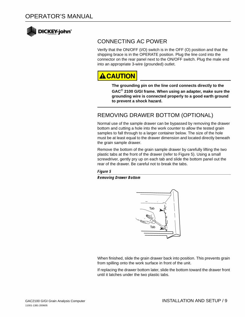
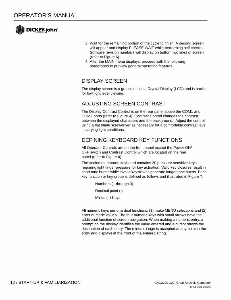
REMOVING DRAWER BOTTOM (OPTIONAL) Normal use of the sample drawer can be bypassed by removing the drawer bottom and cutting a hole into the work counter to allow the tested grain samples to fall through to a larger container below. The size of the hole must be at least equal to the drawer dimension and located directly beneath the grain sample drawer.
Remove the bottom of the grain sample drawer by carefully lifting the two plastic tabs at the front of the drawer (refer to Figure 5). Using a small screwdriver, gently pry up on each tab and slide the bottom panel out the rear of the drawer. Be careful not to break the tabs.
Figure 5Removing Drawer Bottom
When finished, slide the grain drawer back into position. This prevents grain from spilling onto the work surface in front of the unit.
If replacing the drawer bottom later, slide the bottom toward the drawer front until it latches under the two plastic tabs.
Tab
Tab
GAC2100 G/GI Grain Analysis Computer11001-1381-200605
INSTALLATION AND SETUP / 9

OPERATOR’S MANUAL
CHANGING ACCESS CODES An access code is necessary to use certain screens. Whenever the code is required, a screen appears stating ENTER ACCESS CODE. The factory preset access code is set to “0”. To change the access code for security reasons, refer to CHANGING THE ACCESS CODE in the SETTING UP PARAMETERS section.
USING THE COMMUNICATION PORTS Two communication ports are located on the rear of the unit transfer data. These are: (a) Printer Output Port (COM1) and (b) Computer Output Port (COM2). Each must be properly configured to communicate with external devices. Port configuration is described in ESTABLISHING PARAMETERS.
GAC2100 G/GI Grain Analysis Computer11001-1381-200605
10 / INSTALLATION AND SETUP
OPERATOR’S MANUAL
START-UP & FAMILIARIZATION
This section defines the keyboard layout, display messages, and other operator controls.
START-UP PROCEDURE The unit performs a series of self checks every time the unit is powered on to determine the status of the (1) load/strike-off mechanism, (2) unload function, (3) empty test cell weight, and (4) conductance/capacitance measurement circuitry. The self-checks begin when the hopper doors open, the strike-off arm swings across the cell and back again, and the cell dumps. When the cycle ends (about 15 seconds), the MAIN menu displays.
Before starting the procedure below, ensure the ON/OFF (I/O) switch is in the OFF (O) position and that the shipping brace is in the OPERATE position. These are both located on the rear of the unit (refer to Figure 4).
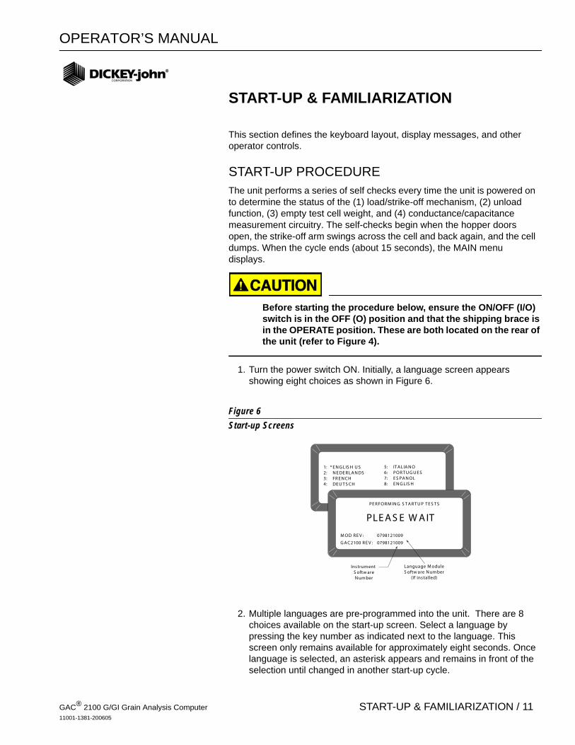
1. Turn the power switch ON. Initially, a language screen appears showing eight choices as shown in Figure 6.
Figure 6Start-up Screens
2. Multiple languages are pre-programmed into the unit. There are 8 choices available on the start-up screen. Select a language by pressing the key number as indicated next to the language. This screen only remains available for approximately eight seconds. Once language is selected, an asterisk appears and remains in front of the selection until changed in another start-up cycle.
1: * E N G LIS H U S2: N E DE R LA N DS3: FR E N CH4: DE U T S CH
5: IT A LIA N O6: POR T U G U E S7: E S PA N OL8: E N G LIS H
PLE A S E W A IT
PE R FOR M IN G S T A R T U P T E S T S
G A C2100 R E V : 0798121009
M OD R E V : 0798121009
Language M oduleS oftw are N um ber
(If installed)
Instrum entS oftw areN um ber
GAC® 2100 G/GI Grain Analysis Computer11001-1381-200605
START-UP & FAMILIARIZATION / 11
OPERATOR’S MANUAL
3. Wait for the remaining portion of the cycle to finish. A second screen will appear and display PLEASE WAIT while performing self checks. Software revision numbers will display on bottom two lines of screen (refer to Figure 6).
4. After the MAIN menu displays, proceed with the followingparagraphs to preview general operating features.
DISPLAY SCREEN The display screen is a graphics Liquid Crystal Display (LCD) and is backlit for low light level viewing.
ADJUSTING SCREEN CONTRAST The Display Contrast Control is on the rear panel above the COM1 and COM2 ports (refer to Figure 4). Contrast Control changes the contrast between the displayed characters and the background. Adjust the control using a flat blade screwdriver as necessary for a comfortable contrast level in varying light conditions.
DEFINING KEYBOARD KEY FUNCTIONS All Operator Controls are on the front panel except the Power ON/OFF switch and Contrast Control which are located on the rear panel (refer to Figure 4). The sealed membrane keyboard contains 20 pressure sensitive keys requiring light finger pressure for key actuation. Valid key closures result in short tone bursts while invalid keystrokes generate longer tone bursts. Each key function or key group is defined as follows and illustrated in Figure 7.
Numbers (1 through 0)
Decimal point (.)
Minus (–) Keys
All numeric keys perform dual functions: (1) make MENU selections and (2) enter numeric values. The four numeric keys with small arrows have the additional function of screen navigation. When making a numeric entry, a prompt on the display identifies the value entered and a cursor shows the destination of each entry. The minus (-) sign is accepted at any point in the entry and displays at the front of the entered string.
GAC2100 G/GI Grain Analysis Computer11001-1381-200605
12 / START-UP & FAMILIARIZATION

OPERATOR’S MANUAL
Figure 7Keyboard Layout
Each entry immediately displays as the cursor moves to the right in preparation for the next entry. Only the first entry of the decimal point is acknowledged.
The Backspace key moves the cursor to the left to delete the last keystroke or to clear an entire entry field.
The Next Page key advances to the next page when the <more> prompt appears in the lower right corner of the display as shown in Figure 8. The NEXT PAGE key sequences the display forward to additional pages of information.
Figure 8Additional Pages Screen
7
1
8 94 5 6
2 30. –
NEXTPAGE Key
ENTERKey
UNLOADKey
PRINTKey
HELPKey
LOADKey
PREVIOUSPAGE Key
BACKSPACEKey
NOTE: Keys 0, 1, 3, and 5 also functions as arrow keys to navigate through certain screens.
DIAGNOSTIC MODE PAGE 1
1: Vnull 5: SCD12: Vtemp 6: SCD23: Cwgt 7: Temp4: Ce/f 8:
SELECT TEST NUMBER <more>
DIAGNOSTIC MODE PAGE 2
5 KHz (D1) 2 MHz (D2)1: Vc 5: Vc2: Vc - Vn 6: Vc - Vn3: Vsc 7: Vsc4: Vsc - Vn 8: Vsc - Vn
SELECT TEST NUMBER
IndicatesAdditional Page
Backspace key
Next Page key
GAC2100 G/GI Grain Analysis Computer11001-1381-200605
START-UP & FAMILIARIZATION / 13
OPERATOR’S MANUAL
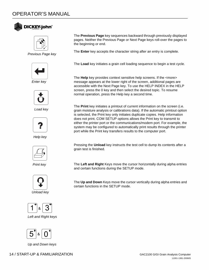
The Previous Page key sequences backward through previously displayed pages. Neither the Previous Page or Next Page keys roll-over the pages to the beginning or end.
The Enter key accepts the character string after an entry is complete.
The Load key initiates a grain cell loading sequence to begin a test cycle.
The Help key provides context sensitive help screens. If the <more> message appears at the lower right of the screen, additional pages are accessible with the Next Page key. To use the HELP INDEX in the HELP screen, press the 0 key and then select the desired topic. To resume normal operation, press the Help key a second time.
The Print key initiates a printout of current information on the screen (i.e. grain moisture analysis or calibrations data). If the automatic printout option is selected, the Print key only initiates duplicate copies. Help information does not print. COM SETUP options allows the Print key to transmit to either the printer port or the communications/modem port. For example, the system may be configured to automatically print results through the printer port while the Print key transfers results to the computer port.
Pressing the Unload key instructs the test cell to dump its contents after a grain test is finished.
The Left and Right Keys move the cursor horizontally during alpha entries and certain functions during the SETUP mode.
The Up and Down Keys move the cursor vertically during alpha entries and certain functions in the SETUP mode.
1 3&
5 0&
Previous Page key
Load key
Enter key
Help key
Print key
Unload key
Left and Right keys
Up and Down keys
GAC2100 G/GI Grain Analysis Computer11001-1381-200605
14 / START-UP & FAMILIARIZATION
OPERATOR’S MANUAL
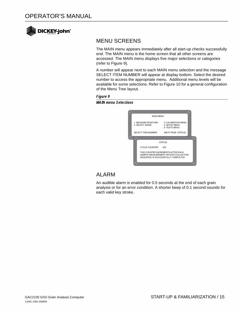
MENU SCREENS The MAIN menu appears immediately after all start-up checks successfully end. The MAIN menu is the home screen that all other screens are accessed. The MAIN menu displays five major selections or categories (refer to Figure 9).
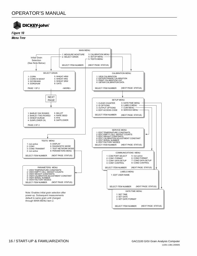
A number will appear next to each MAIN menu selection and the message SELECT ITEM NUMBER will appear at display bottom. Select the desired number to access the appropriate menu. Additional menu levels will be available for some selections. Refer to Figure 10 for a general configuration of the Menu Tree layout.
Figure 9MAIN menu Selections
ALARM An audible alarm is enabled for 0.5 seconds at the end of each grain analysis or for an error condition. A shorter beep of 0.1 second sounds for each valid key stroke.
MAIN MENU
1: MEASURE MOISTURE 3: CALIBRATION MENU2: SELECT GRAIN 4: SETUP MENU 5: TESTS MENU
SELECT ITEM NUMBER (NEXT PAGE: STATUS)
STATUS
CYCLE COUNTER: 435
THIS COUNTER INCREMENTS AFTER EACHSAMPLE MEASUREMENT OR DATA COLLECTIONSEQUENCE IS SUCCESSFULLY COMPLETED
GAC2100 G/GI Grain Analysis Computer11001-1381-200605
START-UP & FAMILIARIZATION / 15
OPERATOR’S MANUAL
Figure 10Menu Tree
MAIN MENU
1: MEASURE MOISTURE2: SELECT GRAIN
SELECT ITEM NUMBER (NEXT PAGE: STATUS)
3: CALIBRATION MENU4: SETUP MENU5: TESTS MENU
SELECT GRAIN
1: CORN2: CORN HI MOIST3: SOYBEANS4: SORGHUM
5: WHEAT HRW4: WHEAT HRS5: WHEAT SRW8: OATS
SETUP MENU
1: CLEAR COUNTER2: ID OPTIONS3: OUTPUT OPTIONS4: EDIT ACCESS CODE
SELECT ITEM NUMBER
5: DATE/TIME MENU6: LABELS MENU7: COM MENU8: SERVICE MENU
COMMUNICATIONS MENU
1: COM PORT SELECT2: COM1 FORMAT3: COM1 DATA SETUP4: COM1 CONTROL
SELECT ITEM NUMBER (NEXT PAGE: STATUS)
5: non-active6: COM2 FORMAT7: COM2 DATA SETUP8: COM2 CONTROL
TESTS MENU
1: non-active2: COM13: COM2 TRANSMIT4: non-active
SELECT ITEM NUMBER (NEXT PAGE: STATUS)
5: DISPLAY6: DIAGNOSTIC MODE7: TEST NETWORK MODE8: PARAMETERS MENU
LABELS MENU
1: EDIT USER NAME
SELECT ITEM NUMBER (NEXT PAGE: STATUS)
DATE/TIME MENU
1: SET TIME2: SET DATE3: SET DATE FORMAT
SELECT ITEM NUMBER (NEXT PAGE: STATUS)
SERVICE MENU1: EDIT TEMPERATURE CONSTANTS2: EDIT EMPTY CELL WEIGHT COUNTS3: EDIT WEIGHT CONSTANTS4: EDIT CALIBRATION ADJUSTMENT CONSTANT5: EDIT SERIAL NUMBER6: EDIT FACTORY MODES
SELECT ITEM NUMBER (NEXT PAGE: STATUS)
PARAMETERS MENU1: VIEW TEMPERATURE CONSTANTS2: VIEW EMPTY CELL WEIGHT COUNTS3: VIEW WEIGHT CONSTANTS4: VIEW CALIBRATION ADJUSTMENT CONSTANT5: VIEW SERIAL NUMBER6: VIEW FACTORY MODES
SELECT ITEM NUMBER (NEXT PAGE: STATUS)
CALIBRATION MENU
1: VIEW CALIBRATION2: ENTER/CHANGE CALIBRATION3: PRINT CALIBRATION LIST4: OBTAIN CALIBRATION DATA
SELECT ITEM NUMBER (NEXT PAGE: STATUS)
(NEXT PAGE: STATUS)
Initial GrainSelection
(See Note Below)
Note: Enables initial grain selection afterpower-up. Subsequent measurements default to same grain until changed through MAIN MENU item 2.
1: BARLEY SIX ROWED2: BARLEY TWO ROWED3: WHEAT DURUM4: SUNFLOWER OIL
5: MILLET4: RAPE SEED5: RYE8: SAFFLOWER
PAGE 1 OF 2 <MORE>
PAGE 2 OF 2
NEXTPAGE
GAC2100 G/GI Grain Analysis Computer11001-1381-200605
16 / START-UP & FAMILIARIZATION
OPERATOR’S MANUAL
MEASURING MOISTURE
The MAIN menu appears immediately after all start-up checks have successfully concluded (refer to START-UP & FAMILIARIZATION). The MAIN menu displays five major selections or categories. This section describes the MEASURE MOISTURE procedure.
PREPARING TO TEST MOISTURE To measure moisture:
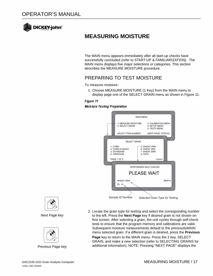
1. Choose MEASURE MOISTURE (1 Key) from the MAIN menu to display page one of the SELECT GRAIN menu as shown in Figure 11.
Figure 11Moisture Testing Preparation
2. Locate the grain type for testing and select the corresponding number to the left. Press the Next Page key if desired grain is not shown on first screen. After selecting a grain, the unit cycles through self-check tests to ensure that the program memory and calibrations are valid. Subsequent moisture measurements default to the previouslyMAIN menu selected grain. If a different grain is desired, press the Previous Page key to return to the MAIN menu. Press the 2 key, SELECT GRAIN, and make a new selection (refer to SELECTING GRAINS for additional information). NOTE: Pressing "NEXT PAGE" displays the
MAIN MENU
1: MEASURE MOISTURE 3: CALIBRATION MENU2: SELECT GRAIN 4: SETUP MENU 5: TESTS MENU
SELECT ITEM NUMBER (NEXT PAGE: STATUS)
SELECT GRAIN
1: CORN 5: WHEAT HRW2: CORN HI MOIST 6: WHEAT HRS3: SOYBEANS 7: WHEAT SRW4: SORGHUM 8: OATS
PAGE 1 OF 2 <more>
PLEASE WAIT
PERFORMING SELF-CHECKS
WHEAT HRW
ID: 14
960918
Sample ID Number Selected Grain Type for Testing
Next Page key
Previous Page key
GAC2100 G/GI Grain Analysis Computer11001-1381-200605
MEASURING MOISTURE / 17

OPERATOR’S MANUAL
second set of eight grains that can be tested with the factory calibration setup.
3. Enter a sample ID number. This number identifies the sample tested on the paper printout. If the ENTER REQUIRED FOR ID is turned on (refer to CHOOSING ID OPTIONS in the ESTABLISHING PARAMETERS section), the ENTER SAMPLE ID screen displays and an ID number is required (refer to Figure 12). Other ID numbering options skip this screen. For now, enter any number and press the ENTER key (i.e. Press 1). Further explanation on using ID numbers are described later in this section.
Figure 12Screen Sequence Using Enter Required for ID
MEASURING MOISTURE (BASIC METHOD) After all selected grain calibration self-checks are finished (approximately 10 seconds), the message FILL SAMPLE HOPPER, ENTER ID NO. THEN…PRESS LOAD TO BEGIN will display (refer to Figure 13). To measure moisture:
1. Pour grain into the sample hopper. Fill the hopper until the grain is at least 1.25 cm (1/2 inch) above the separation line between the hopper top and hopper compartment (heap grain slightly). The exact volume is unimportant except enough grain must be present to overfill the cell (approx .5 liter or 2 cups). Excess grain spills over the cell top and falls into the grain drawer below.
2. If an ID number has not already been entered, enter a number or skip to step 3.
3. Press the Load key on the keyboard to start the test cycle. After pressing the Load key, the hopper doors open to drop the grain into the test cell. The cell fills and the striker arm swings across the top of the test cell to wipe away excess grain.
ENTER SAMPLE ID
WHEAT HRW
ID:
960918
PRESS LOAD TO BEGINWHEAT HRW
ID:AD38
960918
FILL SAMPLE HOPPER AND
Load key
Enter key
GAC2100 G/GI Grain Analysis Computer11001-1381-200605
18 / MEASURING MOISTURE
OPERATOR’S MANUAL
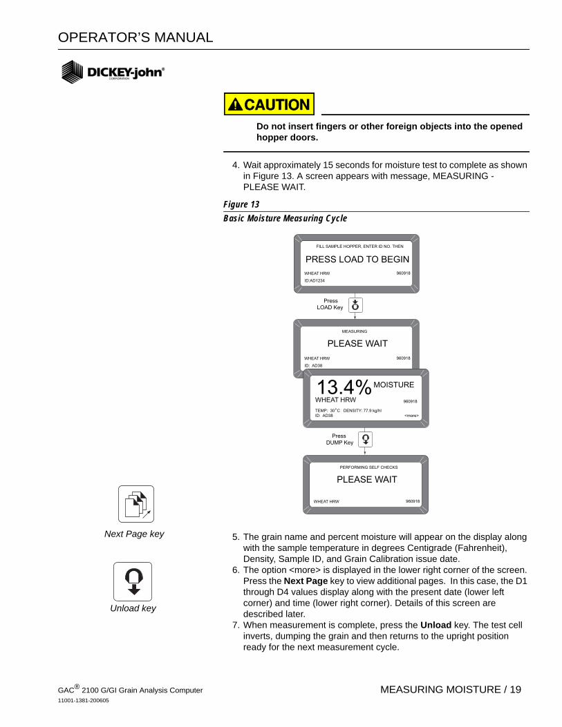
Do not insert fingers or other foreign objects into the opened hopper doors.
4. Wait approximately 15 seconds for moisture test to complete as shown in Figure 13. A screen appears with message, MEASURING - PLEASE WAIT.
Figure 13Basic Moisture Measuring Cycle
5. The grain name and percent moisture will appear on the display along with the sample temperature in degrees Centigrade (Fahrenheit), Density, Sample ID, and Grain Calibration issue date.
6. The option <more> is displayed in the lower right corner of the screen. Press the Next Page key to view additional pages. In this case, the D1 through D4 values display along with the present date (lower left corner) and time (lower right corner). Details of this screen are described later.
7. When measurement is complete, press the Unload key. The test cell inverts, dumping the grain and then returns to the upright position ready for the next measurement cycle.
PLEASE WAIT
MEASURING
WHEAT HRW 960918
ID: AD38
PRESS LOAD TO BEGIN
FILL SAMPLE HOPPER, ENTER ID NO. THEN
WHEAT HRW
ID:AD1234
960918
MOISTURE13.4%WHEAT HRW
TEMP: 30 C DENSITY: 77.9 kg/hl ID: AD38 <more>
960918
PressLOAD Key
PLEASE WAIT
PERFORMING SELF CHECKS
WHEAT HRW 960918
PressDUMP Key
Next Page key
Unload key
GAC® 2100 G/GI Grain Analysis Computer11001-1381-200605
MEASURING MOISTURE / 19

OPERATOR’S MANUAL
8. Start a new moisture measurement for the same grain type. The GAC® 2100 G/GI remembers the grain type until changed or power is turned off. The SELECT GRAIN menu does not appear again until selected.
USING GRAIN SAMPLE ID NUMBERS Grain samples can be identified with three optional ID numbers:
1. Automatic number sequencing (i.e. 1, 2, 3…)2. Manual entry (numbers can be manually entered or skipped)3. ENTER REQUIRED FOR ID (produces an extra screen, ENTER
SAMPLE ID) which prompts a required entry before proceeding (See Figure 12). The ID field can be either numeric or alphanumeric. If numeric only, the digits 0-9, the decimal point and the minus sign are entered with those keys on the keyboard. Other characters are entered from an alpha screen.
ENTERING NUMBERS & ALPHA CHARACTERS Entering alpha characters (letters) into certain screens, such as an ENTER SAMPLE ID number, is accomplished through a special alpha screen. Press the NEXT PAGE key to access the alpha screen from the ENTER SAMPLE ID screen. The Next Page key only functions if an alpha entry is possible.
To view and/or use the alpha screen: 1. Prepare for a moisture test. When the PRESS LOAD TO BEGIN
message appears, observe the ID field in the lower left corner below the grain type. A small cursor is blinking requesting either a number or letter. Numbers are entered directly from the key pad and completed by pressing the Enter key .
2. To enter letters, press the Next Page key to access the alpha screen. The alpha screen shows the alphabet and special characters. In the lower left corner, the word TEXT is displayed. (refer to Figure 14).
Next Page key
Enter key
Backspace key
GAC2100 G/GI Grain Analysis Computer11001-1381-200605
20 / MEASURING MOISTURE

OPERATOR’S MANUAL
Figure 14Alpha Screen
3. Move the vertical pointer (center of screen) to the first letter. The small vertical pointer identifies the selected character. The pointer is moved about the screen using the four arrow keys (left/right and up/down).
4. After selecting a letter, press the Enter key. The letter appears next to the word TEXT on the lower corner. Repeat the process until the phrase is complete. If an error is made, press the Backspace key and re-enter the corrected character.
5. After completing the text string, press Previous Page key. The text string now becomes part of the ID field on the PRESS LOAD TO BEGIN screen. Additional numbers may be inserted after the text string. Deleting is accomplished by entering the alpha screen again and using the Backspace key to delete letters.
USING ID OPTIONS ID numbers are typically used to identify grain samples. The numbers can be a simple number (i.e. 1, 2, 3, etc.), a combination of letters and numbers (i.e. operator’s initials plus sample number) or perhaps the customer’s name (i.e. BROWN). The ID field may contain up to 16 alpha numeric characters.
The ID option is selected through the SETUP MENU, ID OPTIONS (refer to SETTING UP PARAMETERS). ID numbers are added to each tested sample using one of three methods:
1. Inserted manually - Any ID field, including none at all, can be assigned to grain samples before each test. This flexibility allows users to develop individualized numbering schemes.
2. Automatic Sequencing - Numbers can be sequentially assigned automatically to each moisture test. For example, 1, 2, 3, etc. or specific letters (i.e. initials) can be placed in front of the numbers (i.e. JW12). Only the numbers at the end of the field change automatically.
3. Entry required for ID - An ID field is required before each moisture test can proceed. This method ensures each sample is properly identified usually for printer output. A screen appears before a moisture test begins asking the user to ENTER SAMPLE ID. Alpha characters can be used if desired.
ABCDEFGHIJKLMNOPQRSTUVQXYZ _ #$%&'( ) *,-.+
ÇOZÄCÉLLSÖÜTLANZECAAES ADDËNIITUOßONSRUU
Y§R
TEXT: -
“ “´ ´
´
´ ´´ ´ ´ ´ ´ ´
ˆ ˆ
ˆ
ˆ ˆ ˆ ˆˆ ˆ ˆ
ˆ ˆˆ °~
Previous Page key
Enter key
Backspace key
GAC2100 G/GI Grain Analysis Computer11001-1381-200605
MEASURING MOISTURE / 21
OPERATOR’S MANUAL
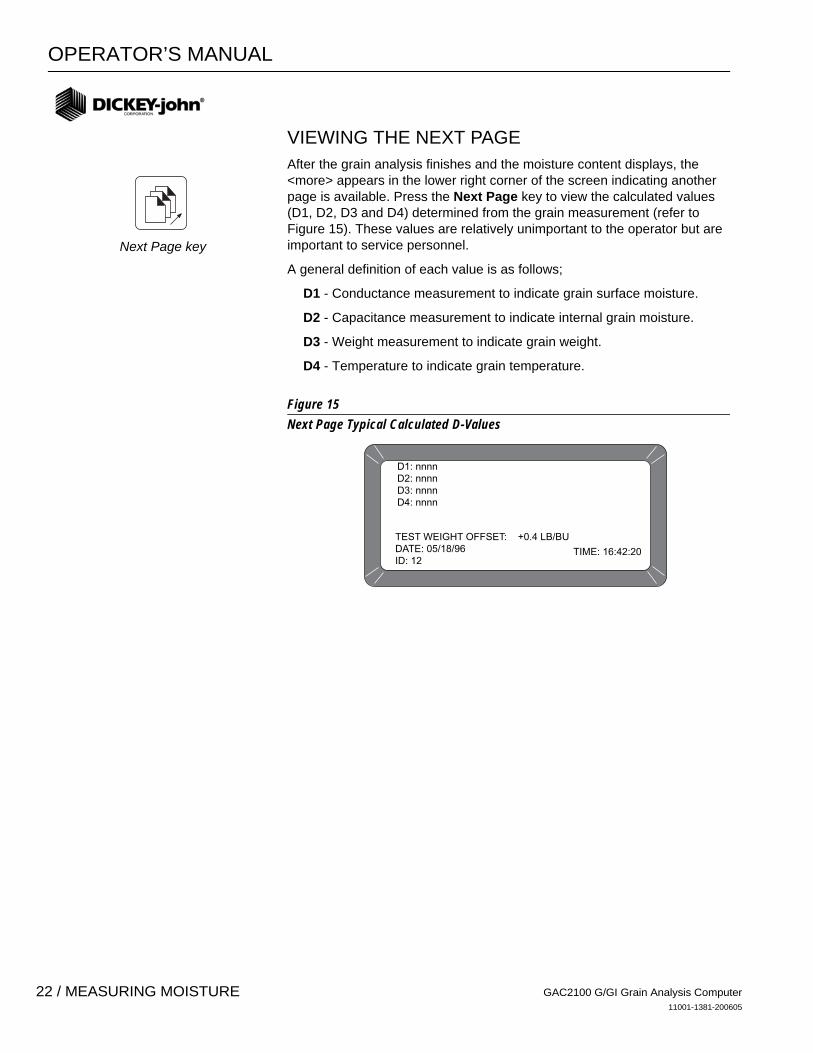
VIEWING THE NEXT PAGE After the grain analysis finishes and the moisture content displays, the <more> appears in the lower right corner of the screen indicating another page is available. Press the Next Page key to view the calculated values (D1, D2, D3 and D4) determined from the grain measurement (refer to Figure 15). These values are relatively unimportant to the operator but are important to service personnel.
A general definition of each value is as follows;
D1 - Conductance measurement to indicate grain surface moisture.
D2 - Capacitance measurement to indicate internal grain moisture.
D3 - Weight measurement to indicate grain weight.
D4 - Temperature to indicate grain temperature.
Figure 15Next Page Typical Calculated D-Values
D1: nnnnD2: nnnnD3: nnnnD4: nnnn
TEST WEIGHT OFFSET: +0.4 LB/BUDATE: 05/18/96ID: 12
TIME: 16:42:20
Next Page key
GAC2100 G/GI Grain Analysis Computer11001-1381-200605
22 / MEASURING MOISTURE
OPERATOR’S MANUAL
GRAIN SELECTION
The second item on the MAIN menu is the SELECT GRAIN menu used to select specific grain types for testing. The SELECT GRAIN menu automatically appears for the first moisture test each time power is applied or can be selected anytime a different grain type is to be tested. After the first test, the SELECT GRAIN menu must be selected manually.
USING SELECT GRAIN MENU The GAC® 2100 G/GI stores up to 16 different grain calibrations. To select a grain for testing:
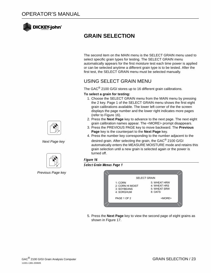
1. Choose the SELECT GRAIN menu from the MAIN menu by pressing the 2 key. Page 1 of the SELECT GRAIN menu shows the first eight grain calibrations available. The lower left corner of the the screen displays the page number and the lower right indicates more pages (refer to Figure 16).
2. Press the Next Page key to advance to the next page. The next eight grain calibration names appear. The <MORE> prompt disappears.
3. Press the PREVIOUS PAGE key to move backward. The Previous Page key is the counterpart to the Next Page key.
4. Press the number key corresponding to the number adjacent to the desired grain. After selecting the grain, the GAC® 2100 G/GI automatically enters the MEASURE MOISTURE mode and retains this grain selection until a new grain is selected again or the power is turned off.
Figure 16Select Grain Menus Page 1
5. Press the Next Page key to view the second page of eight grains as shown in Figure 17.
SELECT GRAIN
1: CORN2: CORN HI MOIST3: SOYBEANS4: SORGHUM
5: WHEAT HRW4: WHEAT HRS5: WHEAT SRW8: OATS
PAGE 1 OF 2 <MORE>
Next Page key
Previous Page key
GAC® 2100 G/GI Grain Analysis Computer11001-1381-200605
GRAIN SELECTION / 23
OPERATOR’S MANUAL
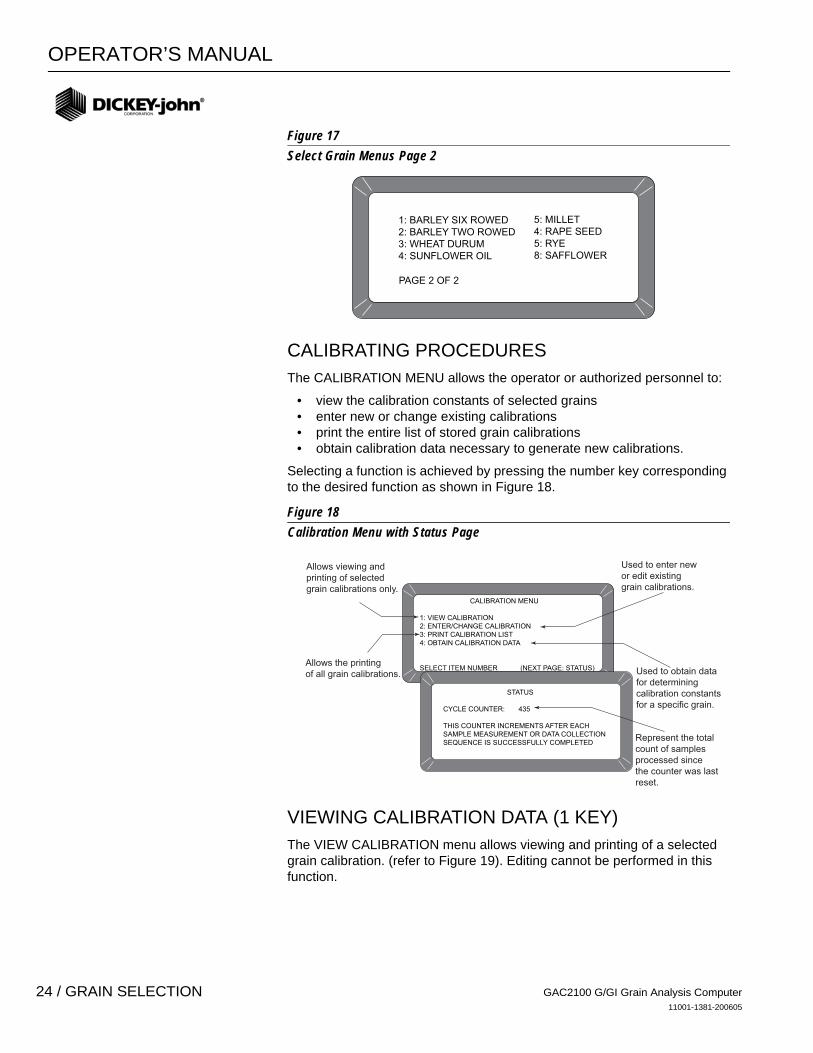
Figure 17Select Grain Menus Page 2
CALIBRATING PROCEDURES The CALIBRATION MENU allows the operator or authorized personnel to:
• view the calibration constants of selected grains • enter new or change existing calibrations• print the entire list of stored grain calibrations • obtain calibration data necessary to generate new calibrations.
Selecting a function is achieved by pressing the number key corresponding to the desired function as shown in Figure 18.
Figure 18Calibration Menu with Status Page
VIEWING CALIBRATION DATA (1 KEY) The VIEW CALIBRATION menu allows viewing and printing of a selected grain calibration. (refer to Figure 19). Editing cannot be performed in this function.
1: BARLEY SIX ROWED2: BARLEY TWO ROWED3: WHEAT DURUM4: SUNFLOWER OIL
5: MILLET4: RAPE SEED5: RYE8: SAFFLOWER
PAGE 2 OF 2
CALIBRATION MENU
1: VIEW CALIBRATION2: ENTER/CHANGE CALIBRATION3: PRINT CALIBRATION LIST4: OBTAIN CALIBRATION DATA
SELECT ITEM NUMBER (NEXT PAGE: STATUS)
STATUS
CYCLE COUNTER: 435
THIS COUNTER INCREMENTS AFTER EACHSAMPLE MEASUREMENT OR DATA COLLECTIONSEQUENCE IS SUCCESSFULLY COMPLETED
Allows viewing andprinting of selectedgrain calibrations only.
Used to enter newor edit existinggrain calibrations.
Allows the printingof all grain calibrations. Used to obtain data
for determining calibration constants for a specific grain.
Represent the total count of samples processed since the counter was last reset.
GAC2100 G/GI Grain Analysis Computer11001-1381-200605
24 / GRAIN SELECTION
OPERATOR’S MANUAL
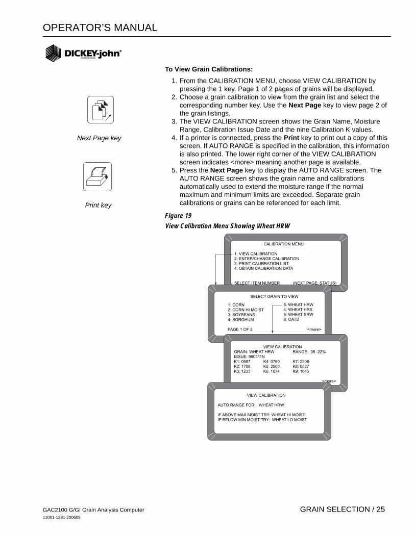
To View Grain Calibrations: 1. From the CALIBRATION MENU, choose VIEW CALIBRATION by
pressing the 1 key. Page 1 of 2 pages of grains will be displayed.2. Choose a grain calibration to view from the grain list and select the
corresponding number key. Use the Next Page key to view page 2 of the grain listings.
3. The VIEW CALIBRATION screen shows the Grain Name, Moisture Range, Calibration Issue Date and the nine Calibration K values.
4. If a printer is connected, press the Print key to print out a copy of this screen. If AUTO RANGE is specified in the calibration, this information is also printed. The lower right corner of the VIEW CALIBRATION screen indicates <more> meaning another page is available.
5. Press the Next Page key to display the AUTO RANGE screen. The AUTO RANGE screen shows the grain name and calibrations automatically used to extend the moisture range if the normal maximum and minimum limits are exceeded. Separate grain calibrations or grains can be referenced for each limit.
Figure 19View Calibration Menu Showing Wheat HRW
CALIBRATION MENU
1: VIEW CALIBRATION2: ENTER/CHANGE CALIBRATION3: PRINT CALIBRATION LIST4: OBTAIN CALIBRATION DATA
SELECT ITEM NUMBER (NEXT PAGE: STATUS)
SELECT GRAIN TO VIEW
VIEW CALIBRATIONGRAIN: WHEAT HRW RANGE: 08 -22%ISSUE: 990311NK1: 0587 K4: 0760 K7: 2208K2: 1708 K5: 2500 K8: 0527K3: 1233 K6: 1074 K9: 1045
<more>
VIEW CALIBRATION AUTO RANGE FOR: WHEAT HRW
IF ABOVE MAX MOIST TRY: WHEAT HI MOISTIF BELOW MIN MOIST TRY: WHEAT LO MOIST
1: CORN2: CORN HI MOIST3: SOYBEANS4: SORGHUM
5: WHEAT HRW4: WHEAT HRS5: WHEAT SRW8: OATS
PAGE 1 OF 2 <more>
Next Page key
Print key
GAC2100 G/GI Grain Analysis Computer11001-1381-200605
GRAIN SELECTION / 25

OPERATOR’S MANUAL
ENTERING/CHANGING CALIBRATION VALUES (2 KEY) To Enter/Change Calibration Values:
1. From the Calibration menu, press the 2 key to access the Enter/Change Calibration scrren.
2. Select the grain to be altered or locate any empty position to enter a new calibration. Select the appropriate key corresponding to the listing. A screen will appear displaying TO PROCEED, UNSEAL ACCESS PORT ON REAR PANEL AND PRESS WHITE PUSHBUTTON. Refer to Figure 20 for additional information.
IMPORTANT: Do not perform this action unless you are authorized
Figure 20Changing Calibrations
CALIBRATION MENU
1: VIEW CALIBRATION2: ENTER/CHANGE CALIBRATION3: PRINT CALIBRATION LIST4: OBTAIN CALIBRATION DATA
SELECT ITEM NUMBER (NEXT PAGE: STATUS)
SELECT GRAIN TO ENTER/CHANGE
ENTER/CHANGE CALIBRATION AUTO RANGE FOR: WHEAT HRW
IF ABOVE MAX MOIST TRY: WHEAT HI MOISTIF BELOW MIN MOIST TRY: WHEAT LO MOIST
TO PROCEED
UNSEAL ACCESS PORT ON REAR PANEL AND DEPRESS WHITE PUSHBUTTON
ENTER/CHANGE CALIBRATION
ENTER/CHANGE CALIBRATIONGRAIN: WHEAT HRW RANGE: 08 -22%
Press to EDIT <more>
ISSUE: 990311N
K1: 0587 K4: 0760 K7: 2208
K2: 1708 K5: 2500 K8: 0527
K3: 1233 K6: 1074 K9: 1045
1: CORN2: CORN HI MOIST3: SOYBEANS4: SORGHUM
5: WHEAT HRW4: WHEAT HRS5: WHEAT SRW8: OATS
PAGE 1 OF 2 <more>
GAC2100 G/GI Grain Analysis Computer11001-1381-200605
26 / GRAIN SELECTION
OPERATOR’S MANUAL
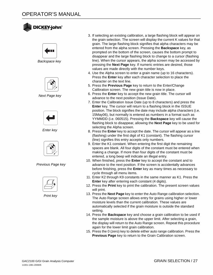
3. If selecting an existing calibration, a large flashing block will appear on the grain selection. The screen will display the current K values for that grain. The large flashing block signifies that alpha characters may be entered from the alpha screen. Pressing the Backspace key, as prompted on the bottom of the screen, causes the bottom prompt to disappear and the large flashing block to change to a cursor (flashing line). When the cursor appears, the alpha screen may be accessed by pressing the Next Page key. If numeric entries are desired, those values are made directly with the number keys.
4. Use the Alpha screen to enter a grain name (up to 16 characters). Press the Enter key after each character selection to place the character on the text line.
5. Press the Previous Page key to return to the Enter/Change Calibration screen. The new grain title is now in place.
6. Press the Enter key to accept the new grain title. The cursor will advance to the next position (Issue Date).
7. Enter the Calibration Issue Date (up to 8 characters) and press the Enter key. The cursor will return to a flashing block in the ISSUE position. The block signifies the date may include alpha characters (i.e. 15May06), but normally is entered as numbers in a format such as YYMMDD (i.e. 060515). Pressing the Backspace key will cause the flashing block to disappear, allowing the Next Page key to be used for selecting the Alpha screen.
8. Press the Enter key to accept the date. The cursor will appear as a line (flashing) under the first digit of K1 (constant). The flashing cursor (line) signifies this entry accepts only numbers.
9. Enter the K1 constant. When entering the first digit the remaining spaces are blank. All four digits of the constant must be entered when making a change. If more than four digits of the constant must be entered, a long beep will indicate an illegal entry.
10. When finished, press the Enter key to accept the constant and to advance to the next position. If the screen is accidentally advances before finishing, press the Enter key as many times as necessary to cycle through all menu items.
11. Enter K2 through K9 constants in the same manner as K1. Press the Enter key after entering each constant (4 digits).
12. Press the Print key to print the calibration. The present screen values will print.
13. Press the Next Page key to enter the Auto Range calibration selection. The Auto Range screen allows entry for grains using higher or lower moisture levels than the current calibration. These values are automatically selected if the grain moisture is outside the standard setting.
14. Press the Backspace key and choose a grain calibration to be used if the sample moisture is above the upper limit. After selecting a grain, the display will return to the Auto Range screen. Repeat this procedure again for the lower limit grain calibration.
15. Press the 0 (zero) key to delete either auto range calibration. Press the Previous Page key to return to the Grain Calibration screen.
Backspace key
Next Page key
Enter key
Previous Page key
Print key
GAC2100 G/GI Grain Analysis Computer11001-1381-200605
GRAIN SELECTION / 27
OPERATOR’S MANUAL
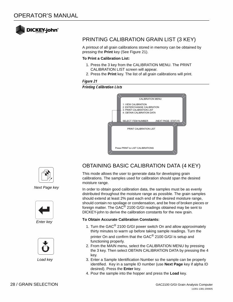
PRINTING CALIBRATION GRAIN LIST (3 KEY) A printout of all grain calibrations stored in memory can be obtained by pressing the Print key (See Figure 21).
To Print a Calibration List: 1. Press the 3 key from the CALIBRATION MENU. The PRINT
CALIBRATION LIST screen will appear. 2. Press the Print key. The list of all grain calibrations will print.
Figure 21Printing Calibration Lists
OBTAINING BASIC CALIBRATION DATA (4 KEY) This mode allows the user to generate data for developing grain calibrations. The samples used for calibration should span the desired moisture range.
In order to obtain good calibration data, the samples must be as evenly distributed throughout the moisture range as possible. The grain samples should extend at least 2% past each end of the desired moisture range, should contain no spoilage or condensation, and be free of broken pieces or foreign matter. The GAC® 2100 G/GI readings obtained may be sent to DlCKEY-john to derive the calibration constants for the new grain.
To Obtain Accurate Calibration Constants:
1. Turn the GAC® 2100 G/GI power switch On and allow approximately thirty minutes to warm up before taking sample readings. Turn the printer On and confirm that the GAC® 2100 G/GI is setup and functioning properly.
2. From the MAIN menu, select the CALIBRATION MENU by pressing the 3 key. Then select OBTAIN CALIBRATION DATA by pressing the 4 key.
3. Enter a Sample Identification Number so the sample can be properly identified. Key in a sample ID number (use Next Page key if alpha ID desired). Press the Enter key.
4. Pour the sample into the hopper and press the Load key.
CALIBRATION MENU
1: VIEW CALIBRATION2: ENTER/CHANGE CALIBRATION3: PRINT CALIBRATION LIST4: OBTAIN CALIBRATION DATA
SELECT ITEM NUMBER (NEXT PAGE: STATUS)
PRINT CALIBRATION LIST
Press PRINT to LIST CALIBRATIONS
Next Page key
Enter key
Load key
GAC2100 G/GI Grain Analysis Computer11001-1381-200605
28 / GRAIN SELECTION
OPERATOR’S MANUAL
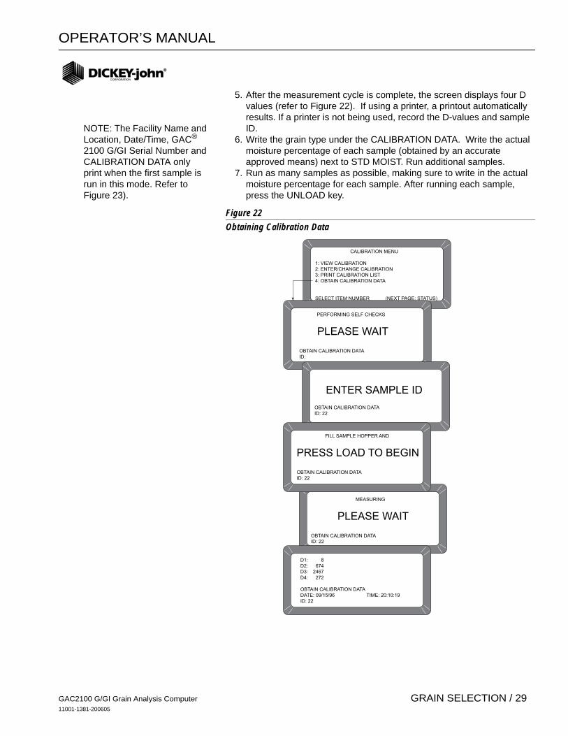
5. After the measurement cycle is complete, the screen displays four D values (refer to Figure 22). If using a printer, a printout automatically results. If a printer is not being used, record the D-values and sample ID.
6. Write the grain type under the CALIBRATION DATA. Write the actual moisture percentage of each sample (obtained by an accurate approved means) next to STD MOIST. Run additional samples.
7. Run as many samples as possible, making sure to write in the actual moisture percentage for each sample. After running each sample, press the UNLOAD key.
Figure 22Obtaining Calibration Data
CALIBRATION MENU
1: VIEW CALIBRATION2: ENTER/CHANGE CALIBRATION3: PRINT CALIBRATION LIST4: OBTAIN CALIBRATION DATA
SELECT ITEM NUMBER (NEXT PAGE: STATUS)
PERFORMING SELF CHECKS
PLEASE WAIT
OBTAIN CALIBRATION DATAID:
ENTER SAMPLE ID
OBTAIN CALIBRATION DATAID: 22
FILL SAMPLE HOPPER AND
PRESS LOAD TO BEGIN
OBTAIN CALIBRATION DATAID: 22
MEASURING
PLEASE WAIT
OBTAIN CALIBRATION DATAID: 22
D1: 8D2: 674D3: 2467D4: 272
OBTAIN CALIBRATION DATADATE: 09/15/96 TIME: 20:10:19ID: 22
NOTE: The Facility Name and Location, Date/Time, GAC®
2100 G/GI Serial Number and CALIBRATION DATA only print when the first sample is run in this mode. Refer to Figure 23).
GAC2100 G/GI Grain Analysis Computer11001-1381-200605
GRAIN SELECTION / 29

OPERATOR’S MANUAL
Figure 23Calibration Data Printout
DICKEY-JOHN10653
04/21/98 06:42:33
S/N: 1640-10653
CALIBRATION DATA
==================
ID: 1
STD. MOIST:
D1: 0D2: 14D3: 2D4: 179
==================
GAC2100 G/GI Grain Analysis Computer11001-1381-200605
30 / GRAIN SELECTION
OPERATOR’S MANUAL
ESTABLISHING PARAMETERS
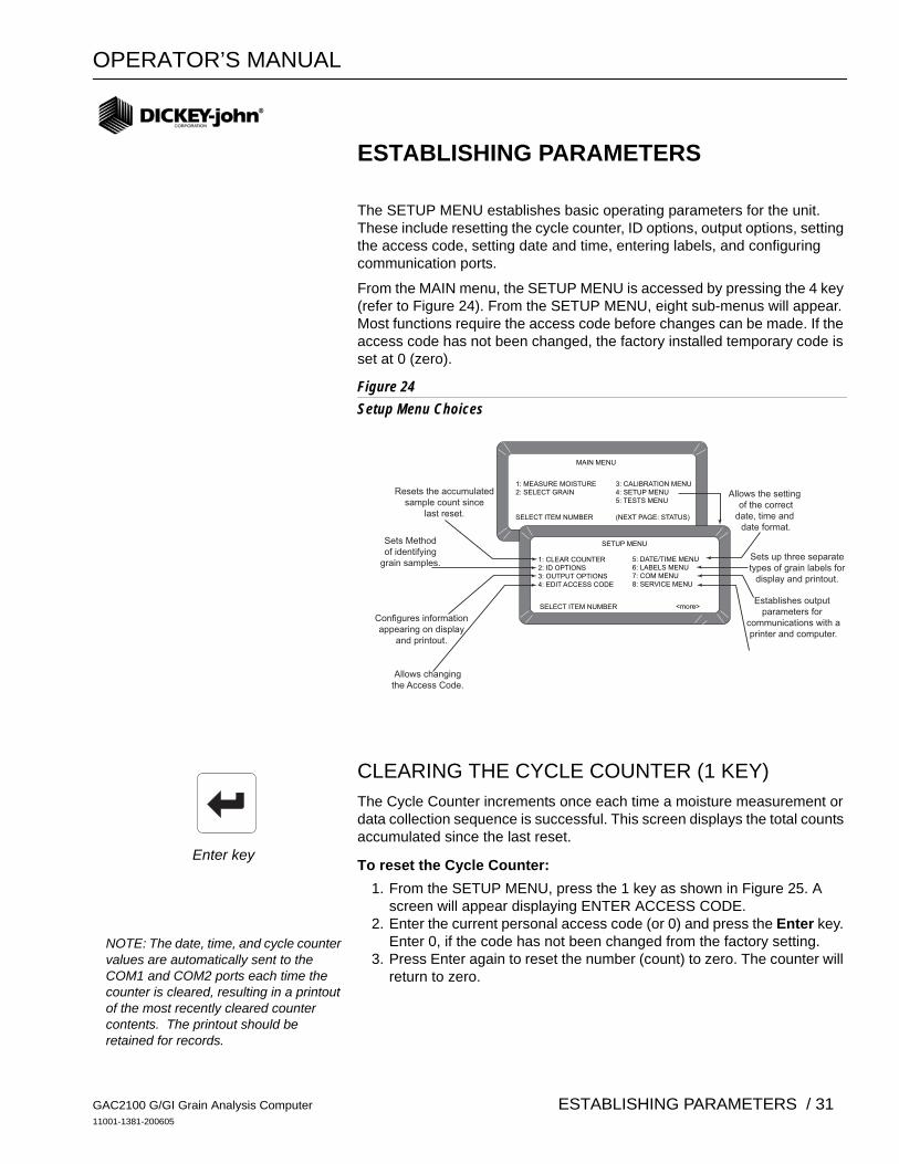
The SETUP MENU establishes basic operating parameters for the unit. These include resetting the cycle counter, ID options, output options, setting the access code, setting date and time, entering labels, and configuring communication ports.
From the MAIN menu, the SETUP MENU is accessed by pressing the 4 key (refer to Figure 24). From the SETUP MENU, eight sub-menus will appear. Most functions require the access code before changes can be made. If the access code has not been changed, the factory installed temporary code is set at 0 (zero).
Figure 24Setup Menu Choices
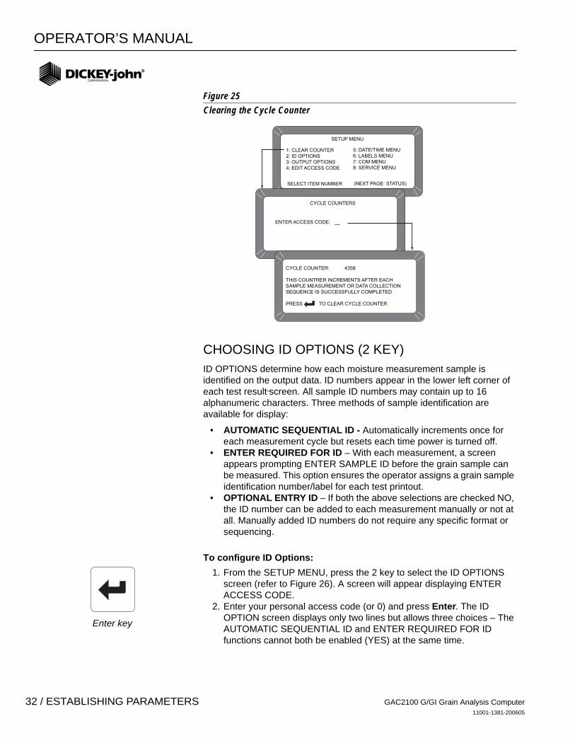
CLEARING THE CYCLE COUNTER (1 KEY) The Cycle Counter increments once each time a moisture measurement or data collection sequence is successful. This screen displays the total counts accumulated since the last reset.
To reset the Cycle Counter: 1. From the SETUP MENU, press the 1 key as shown in Figure 25. A
screen will appear displaying ENTER ACCESS CODE.2. Enter the current personal access code (or 0) and press the Enter key.
Enter 0, if the code has not been changed from the factory setting.3. Press Enter again to reset the number (count) to zero. The counter will
return to zero.
MAIN MENU
1: MEASURE MOISTURE 3: CALIBRATION MENU2: SELECT GRAIN 4: SETUP MENU 5: TESTS MENU
SELECT ITEM NUMBER (NEXT PAGE: STATUS)
SETUP MENU
1: CLEAR COUNTER2: ID OPTIONS3: OUTPUT OPTIONS4: EDIT ACCESS CODE
SELECT ITEM NUMBER <more>
5: DATE/TIME MENU6: LABELS MENU7: COM MENU8: SERVICE MENU
Resets the accumulatedsample count since
last reset.
Sets Methodof identifying
grain samples.
Configures informationappearing on display
and printout.
Allows changingthe Access Code.
Allows the setting of the correct
date, time and date format.
Sets up three separatetypes of grain labels for
display and printout.
Establishes output parameters for
communications with aprinter and computer.
Enter key
NOTE: The date, time, and cycle counter values are automatically sent to the COM1 and COM2 ports each time the counter is cleared, resulting in a printout of the most recently cleared counter contents. The printout should be retained for records.
GAC2100 G/GI Grain Analysis Computer11001-1381-200605
ESTABLISHING PARAMETERS / 31
OPERATOR’S MANUAL
Figure 25 Clearing the Cycle Counter
CHOOSING ID OPTIONS (2 KEY) ID OPTIONS determine how each moisture measurement sample is identified on the output data. ID numbers appear in the lower left corner of each test result screen. All sample ID numbers may contain up to 16 alphanumeric characters. Three methods of sample identification are available for display:
• AUTOMATIC SEQUENTIAL ID - Automatically increments once for each measurement cycle but resets each time power is turned off.
• ENTER REQUIRED FOR ID – With each measurement, a screen appears prompting ENTER SAMPLE ID before the grain sample can be measured. This option ensures the operator assigns a grain sample identification number/label for each test printout.
• OPTIONAL ENTRY ID – If both the above selections are checked NO, the ID number can be added to each measurement manually or not at all. Manually added ID numbers do not require any specific format or sequencing.
To configure ID Options: 1. From the SETUP MENU, press the 2 key to select the ID OPTIONS
screen (refer to Figure 26). A screen will appear displaying ENTER ACCESS CODE.
2. Enter your personal access code (or 0) and press Enter. The ID OPTION screen displays only two lines but allows three choices – The AUTOMATIC SEQUENTIAL ID and ENTER REQUIRED FOR ID functions cannot both be enabled (YES) at the same time.
SETUP MENU
1: CLEAR COUNTER2: ID OPTIONS3: OUTPUT OPTIONS4: EDIT ACCESS CODE
SELECT ITEM NUMBER (NEXT PAGE: STATUS)
5: DATE/TIME MENU6: LABELS MENU7: COM MENU8: SERVICE MENU
CYCLE COUNTERS
ENTER ACCESS CODE: __
CYCLE COUNTER: 4358
THIS COUNTRER INCREMENTS AFTER EACHSAMPLE MEASUREMENT OR DATA COLLECTIONSEQUENCE IS SUCCESSFULLY COMPLETED
PRESS TO CLEAR CYCLE COUNTER
Enter key
GAC2100 G/GI Grain Analysis Computer11001-1381-200605
32 / ESTABLISHING PARAMETERS
OPERATOR’S MANUAL
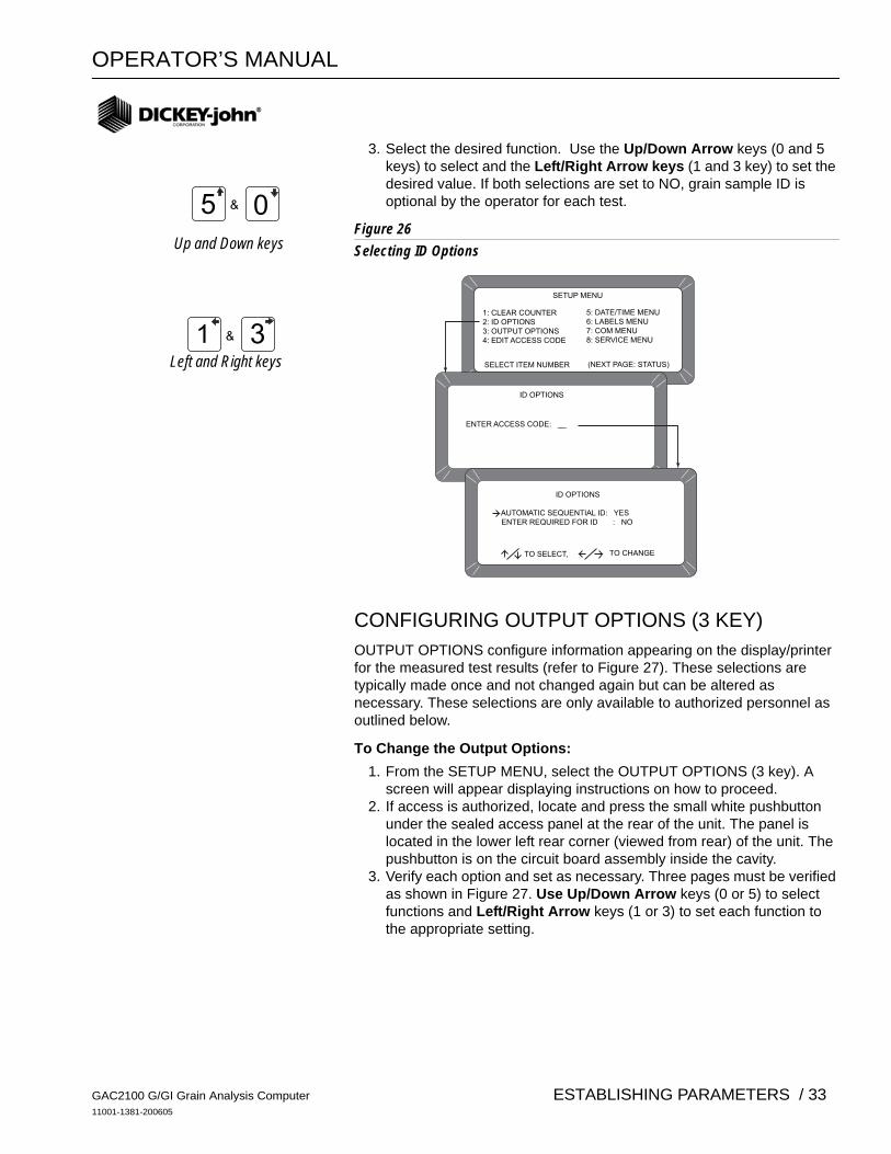
3. Select the desired function. Use the Up/Down Arrow keys (0 and 5 keys) to select and the Left/Right Arrow keys (1 and 3 key) to set the desired value. If both selections are set to NO, grain sample ID is optional by the operator for each test.
Figure 26Selecting ID Options
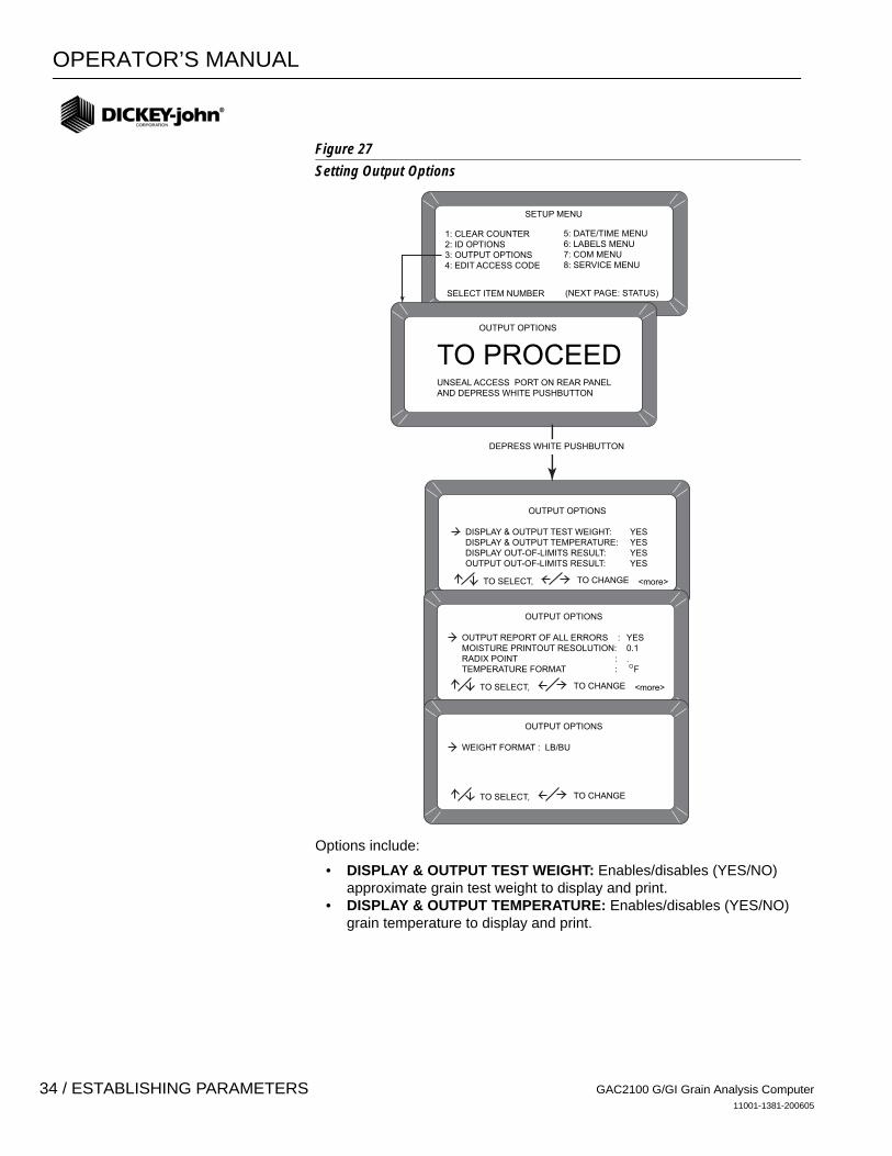
CONFIGURING OUTPUT OPTIONS (3 KEY) OUTPUT OPTIONS configure information appearing on the display/printer for the measured test results (refer to Figure 27). These selections are typically made once and not changed again but can be altered as necessary. These selections are only available to authorized personnel as outlined below.
To Change the Output Options: 1. From the SETUP MENU, select the OUTPUT OPTIONS (3 key). A
screen will appear displaying instructions on how to proceed. 2. If access is authorized, locate and press the small white pushbutton
under the sealed access panel at the rear of the unit. The panel is located in the lower left rear corner (viewed from rear) of the unit. The pushbutton is on the circuit board assembly inside the cavity.
3. Verify each option and set as necessary. Three pages must be verified as shown in Figure 27. Use Up/Down Arrow keys (0 or 5) to select functions and Left/Right Arrow keys (1 or 3) to set each function to the appropriate setting.
5 0&
1 3&
SETUP MENU
1: CLEAR COUNTER2: ID OPTIONS3: OUTPUT OPTIONS4: EDIT ACCESS CODE
SELECT ITEM NUMBER (NEXT PAGE: STATUS)
5: DATE/TIME MENU6: LABELS MENU7: COM MENU8: SERVICE MENU
ID OPTIONS
ENTER ACCESS CODE: __
ID OPTIONS
AUTOMATIC SEQUENTIAL ID: YES ENTER REQUIRED FOR ID : NO
TO SELECT, TO CHANGE
Up and Down keys
Left and Right keys
GAC2100 G/GI Grain Analysis Computer11001-1381-200605
ESTABLISHING PARAMETERS / 33
OPERATOR’S MANUAL
Figure 27Setting Output Options
Options include:
• DISPLAY & OUTPUT TEST WEIGHT: Enables/disables (YES/NO) approximate grain test weight to display and print.
• DISPLAY & OUTPUT TEMPERATURE: Enables/disables (YES/NO) grain temperature to display and print.
OUTPUT OPTIONS
DISPLAY & OUTPUT TEST WEIGHT: YES DISPLAY & OUTPUT TEMPERATURE: YES DISPLAY OUT-OF-LIMITS RESULT: YES OUTPUT OUT-OF-LIMITS RESULT: YES
SETUP MENU
1: CLEAR COUNTER2: ID OPTIONS3: OUTPUT OPTIONS4: EDIT ACCESS CODE
SELECT ITEM NUMBER (NEXT PAGE: STATUS)
5: DATE/TIME MENU6: LABELS MENU7: COM MENU8: SERVICE MENU
OUTPUT OPTIONS
TO PROCEEDUNSEAL ACCESS PORT ON REAR PANELAND DEPRESS WHITE PUSHBUTTON
TO SELECT, TO CHANGE <more>
OUTPUT OPTIONS
OUTPUT REPORT OF ALL ERRORS : YES MOISTURE PRINTOUT RESOLUTION: 0.1 RADIX POINT : . TEMPERATURE FORMAT : F
TO SELECT, TO CHANGE <more>
OUTPUT OPTIONS
WEIGHT FORMAT : LB/BU
TO SELECT, TO CHANGE
DEPRESS WHITE PUSHBUTTON
GAC2100 G/GI Grain Analysis Computer11001-1381-200605
34 / ESTABLISHING PARAMETERS
OPERATOR’S MANUAL
• DISPLAY OUT-OF-LIMITS RESULT: Error messages flash on the display each time tested grain parameters exceed the normal range of that particular grain. If enabled, three standard parameters are displayed – moisture, grain temperature and approximate grain test weight. Each measured parameter value appears next to its respective legend on the display. The display out-of-limit options selected below establish whether or not the enabled values appear on the display. Eight separate settings are available for suppressing the enabled grain parameters.
1. YES - Enabled readings display for all out-of-limit conditions. 2. NO - Enabled readings do not display for any out-of-limit condition.3. M - Enabled readings display if moisture is out-of- limits but do not
display if either weight and/or temperature is out-of-limits. 4. W - Enabled readings display if weight is out-of-limits but do not
display if either moisture and/or temperature is out-of-limits.5. T - Enabled readings display if temperature is out-of-limits but do not
display if either weight and/or moisture is out-of-limits.6. MW- Enabled readings display if moisture and/or weight is out-of-limits
but do not display if temperature is out of limits. 7. MT - Enabled readings display if moisture and/or temperature is
out-of-limits but do not display if weight is out-of-limits. 8. WT - Enabled readings display if weight and/or temperature is
out-of-limits but do not display if moisture is out-of-limits.
• OUTPUT OUT-OF-LIMITS RESULT: If enabled, three standard parameters are printed – moisture, grain temperature and approximate grain test weight. Each measured parameter value appears next to its respective legend on the printout. The output out-of-limit options selected establish whether or not the enabled values print. These choices are identical to the display out-of-limits conditions above and are selected in a similar fashion.
• OUTPUT REPORT OF ALL ERRORS: Enables all internal checked errors to print.
• MOISTURE PRINTOUT RESOLUTION: Selects the resolution to either one tenth (0.1) percent or one hundredth (0.01) percent for moisture printout.
• RADIX POINT: Selects a decimal point ( . ) or comma ( , ) to display and printout.
• TEMPERATURE FORMAT: Selects either degrees C (°C) or degrees F (°F) to display and print out for temperature.
• WEIGHT FORMAT: Selects either pounds per bushel (lb/bu) or kilograms per hectoliter (kg/hl) to display and printout.
GAC2100 G/GI Grain Analysis Computer11001-1381-200605
ESTABLISHING PARAMETERS / 35
OPERATOR’S MANUAL
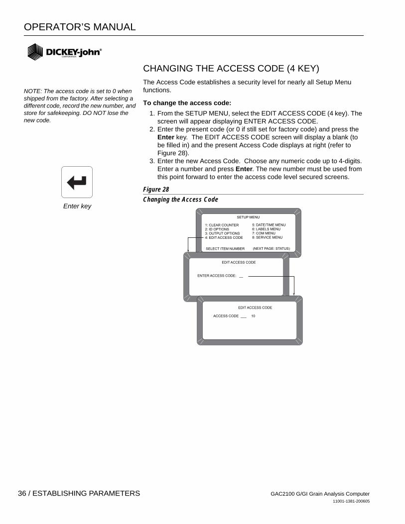
CHANGING THE ACCESS CODE (4 KEY) The Access Code establishes a security level for nearly all Setup Menu functions.
To change the access code: 1. From the SETUP MENU, select the EDIT ACCESS CODE (4 key). The
screen will appear displaying ENTER ACCESS CODE. 2. Enter the present code (or 0 if still set for factory code) and press the
Enter key. The EDIT ACCESS CODE screen will display a blank (to be filled in) and the present Access Code displays at right (refer to Figure 28).
3. Enter the new Access Code. Choose any numeric code up to 4-digits. Enter a number and press Enter. The new number must be used from this point forward to enter the access code level secured screens.
Figure 28 Changing the Access Code
SETUP MENU
1: CLEAR COUNTER2: ID OPTIONS3: OUTPUT OPTIONS4: EDIT ACCESS CODE
SELECT ITEM NUMBER (NEXT PAGE: STATUS)
5: DATE/TIME MENU6: LABELS MENU7: COM MENU8: SERVICE MENU
EDIT ACCESS CODE
ENTER ACCESS CODE: __
EDIT ACCESS CODE
ACCESS CODE ___ 10
NOTE: The access code is set to 0 when shipped from the factory. After selecting a different code, record the new number, and store for safekeeping. DO NOT lose the new code.
Enter key
GAC2100 G/GI Grain Analysis Computer11001-1381-200605
36 / ESTABLISHING PARAMETERS
OPERATOR’S MANUAL
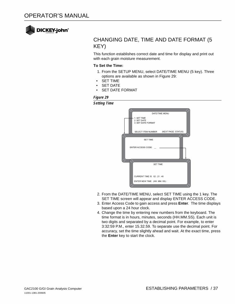
CHANGING DATE, TIME AND DATE FORMAT (5 KEY)This function establishes correct date and time for display and print out with each grain moisture measurement.
To Set the Time: 1. From the SETUP MENU, select DATE/TIME MENU (5 key). Three
options are available as shown in Figure 29:• SET TIME• SET DATE• SET DATE FORMAT
Figure 29Setting Time
2. From the DATE/TIME MENU, select SET TIME using the 1 key. The SET TIME screen will appear and display ENTER ACCESS CODE.
3. Enter Access Code to gain access and press Enter. The time displays based upon a 24 hour clock.
4. Change the time by entering new numbers from the keyboard. The time format is in hours, minutes, seconds (HH.MM.SS). Each unit is two digits and separated by a decimal point. For example, to enter 3:32:59 P.M., enter 15.32.59. To separate use the decimal point. For accuracy, set the time slightly ahead and wait. At the exact time, press the Enter key to start the clock.
DATE/TIME MENU
1: SET TIME2: SET DATE3: SET DATE FORMAT
SELECT ITEM NUMBER (NEXT PAGE: STATUS)
SET TIME
ENTER ACCESS CODE: __
SET TIME
CURRENT TIME IS 02 : 21 : 40
ENTER NEW TIME (HH. MM. SS) :
GAC2100 G/GI Grain Analysis Computer11001-1381-200605
ESTABLISHING PARAMETERS / 37
OPERATOR’S MANUAL
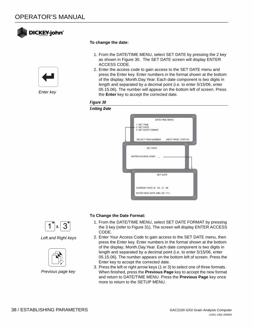
To change the date:
1. From the DATE/TIME MENU, select SET DATE by pressing the 2 key as shown in Figure 30. The SET DATE screen will display ENTER ACCESS CODE.
2. Enter the access code to gain access to the SET DATE menu and press the Enter key. Enter numbers in the format shown at the bottom of the display; Month.Day.Year. Each date component is two digits in length and separated by a decimal point (i.e. to enter 5/15/06, enter 05.15.06). The number will appear on the bottom left of screen. Press the Enter key to accept the corrected date.
Figure 30
Setting Date
To Change the Date Format: 1. From the DATE/TIME MENU, select SET DATE FORMAT by pressing
the 3 key (refer to Figure 31). The screen will display ENTER ACCESS CODE.
2. Enter Your Access Code to gain access to the SET DATE menu, then press the Enter key. Enter numbers in the format shown at the bottom of the display; Month.Day.Year. Each date component is two digits in length and separated by a decimal point (i.e. to enter 5/15/06, enter 05.15.06). The number appears on the bottom left of screen. Press the Enter key to accept the corrected date.
3. Press the left or right arrow keys (1 or 3) to select one of three formats. When finished, press the Previous Page key to accept the new format and return to DATE/TIME MENU. Press the Previous Page key once more to return to the SETUP MENU.
DATE/TIME MENU
1: SET TIME2: SET DATE3: SET DATE FORMAT
SELECT ITEM NUMBER (NEXT PAGE: STATUS)
SET DATE
ENTER ACCESS CODE: __
SET DATE
CURRENT DATE IS 09 : 21 : 96
ENTER NEW DATE (MM. DD. YY) :
1 3&
Enter key
Left and Right keys
Previous page key
GAC2100 G/GI Grain Analysis Computer11001-1381-200605
38 / ESTABLISHING PARAMETERS
OPERATOR’S MANUAL
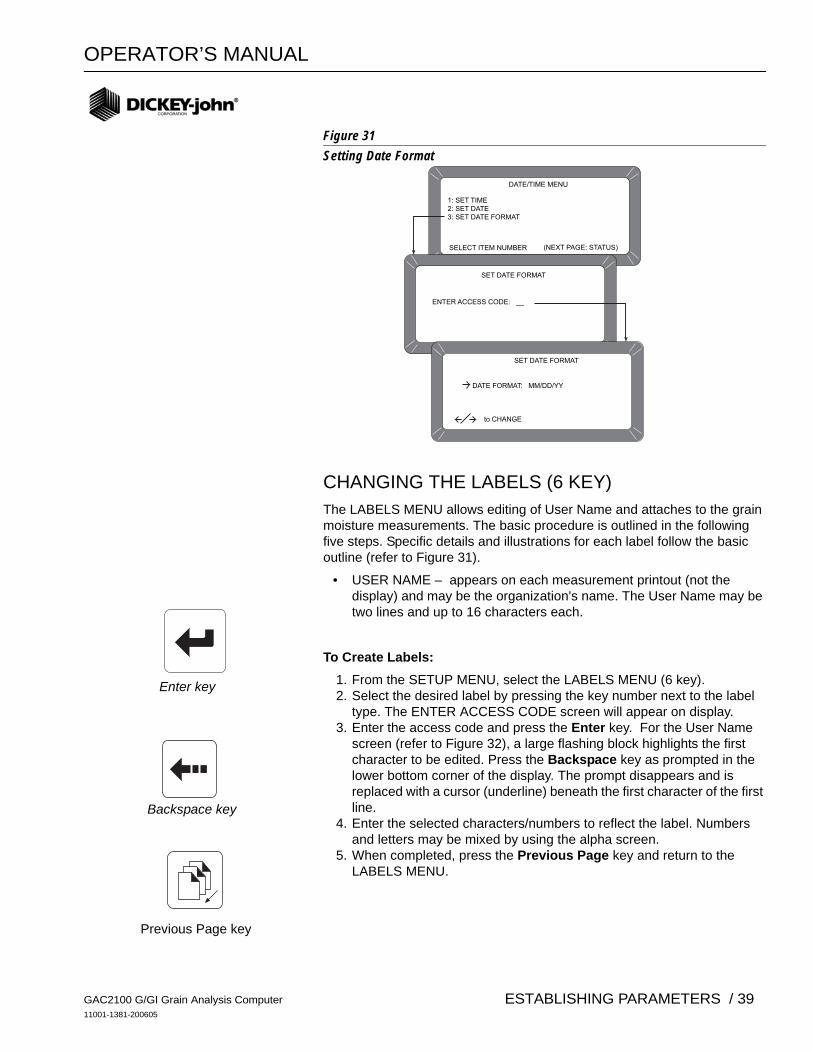
Figure 31Setting Date Format
CHANGING THE LABELS (6 KEY) The LABELS MENU allows editing of User Name and attaches to the grain moisture measurements. The basic procedure is outlined in the following five steps. Specific details and illustrations for each label follow the basic outline (refer to Figure 31).
• USER NAME – appears on each measurement printout (not the display) and may be the organization's name. The User Name may be two lines and up to 16 characters each.
To Create Labels: 1. From the SETUP MENU, select the LABELS MENU (6 key). 2. Select the desired label by pressing the key number next to the label
type. The ENTER ACCESS CODE screen will appear on display. 3. Enter the access code and press the Enter key. For the User Name
screen (refer to Figure 32), a large flashing block highlights the first character to be edited. Press the Backspace key as prompted in the lower bottom corner of the display. The prompt disappears and is replaced with a cursor (underline) beneath the first character of the first line.
4. Enter the selected characters/numbers to reflect the label. Numbers and letters may be mixed by using the alpha screen.
5. When completed, press the Previous Page key and return to the LABELS MENU.
DATE/TIME MENU
1: SET TIME2: SET DATE3: SET DATE FORMAT
SELECT ITEM NUMBER (NEXT PAGE: STATUS)
SET DATE FORMAT
ENTER ACCESS CODE: __
SET DATE FORMAT
DATE FORMAT: MM/DD/YY
to CHANGE
Enter key
Backspace key
Previous Page key
GAC2100 G/GI Grain Analysis Computer11001-1381-200605
ESTABLISHING PARAMETERS / 39
OPERATOR’S MANUAL
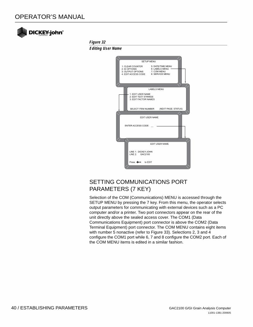
Figure 32Editing User Name
SETTING COMMUNICATIONS PORT PARAMETERS (7 KEY) Selection of the COM (Communications) MENU is accessed through the SETUP MENU by pressing the 7 key. From this menu, the operator selects output parameters for communicating with external devices such as a PC computer and/or a printer. Two port connectors appear on the rear of the unit directly above the sealed access cover. The COM1 (Data Communications Equipment) port connector is above the COM2 (Data Terminal Equipment) port connector. The COM MENU contains eight items with number 5 nonactive (refer to Figure 33). Selections 2, 3 and 4 configure the COM1 port while 6, 7 and 8 configure the COM2 port. Each of the COM MENU items is edited in a similar fashion.
LABELS MENU
1: EDIT USER NAME2: EDIT TEXT STRINGS3: EDIT FACTOR NAMES
SELECT ITEM NUMBER (NEXT PAGE: STATUS)
EDIT USER NAME
ENTER ACCESS CODE: __
EDIT USER NAME
LINE 1: DICKEY-JOHNLINE 2: GAC2100
Press to EDIT
SETUP MENU
1: CLEAR COUNTER2: ID OPTIONS3: OUTPUT OPTIONS4: EDIT ACCESS CODE
5: DATE/TIME MENU6: LABELS MENU7: COM MENU8: SERVICE MENU
GAC2100 G/GI Grain Analysis Computer11001-1381-200605
40 / ESTABLISHING PARAMETERS

OPERATOR’S MANUAL
Figure 33Accessing the COM Menu
To Configure the Communications Ports
(Basic entry procedure – Follow-up to specific subject for finishing details):
1. From the MAIN menu, press the 4 key (SETUP MENU) followed by the 7 key (COM MENU). The COMMUNICATIONS MENU will appear with seven active choices and one nonactive selection.
2. Choose the desired function by pressing the key number next to the choice. The ENTER ACCESS CODE screen will appear.
3. Enter the access code and press the Enter key. The selected COM screen will appear for editing.
4. Proceed with the necessary editing. The selections are: – COM PORT SELECT – COM1 or COM2 FORMAT – COM1 or COM2 SERIAL DATA SETUP – COM1 or COM2 CONTROL LEAD SETUP
To Configure COM PORT SELECT press the 1 key from the COMMUNICATIONS MENU.
1. After completing Steps 1 through 4 from the basic entry procedure, edit the configuration. Four items appear on the menu for editing and configuring output information of both ports (COM1 and COM2). Each item can be set to NONE, COM1, COM2 or COM1/COM2 (both ports) using the Left/Right Arrow keys to cycle through the choices. The pointer in front of each item can be moved with the Up/Down Arrow keys.
SELECT ITEM NUMBER (NEXT PAGE: STATUS)
SETUP MENU
1: CLEAR COUNTER2: ID OPTIONS3: OUTPUT OPTIONS4: EDIT ACCESS CODE
5: DATE/TIME MENU6: LABELS MENU7: COM MENU8: SERVICE MENU
COMMUNICATIONS MENU
1: COM PORT SELECT2: COM1 FORMAT3: COM1 DATA SETUP4: COM1 CONTROL
5: non-active6: COM2 FORMAT7: COM2 DATA SETUP8: COM2 CONTROL
SELECT ITEM NUMBER (NEXT PAGE: STATUS)
1 3&
5 0&
Enter key
Left & Right keys
Up & Down keys
GAC2100 G/GI Grain Analysis Computer11001-1381-200605
ESTABLISHING PARAMETERS / 41

OPERATOR’S MANUAL
Figure 34
Accessing COM PORT SELECT
The four outputs are defined as follows (refer to Figure 34):
– AUTOMATIC RESULTS OUTPUT - the configured port produces an output to automatically printout the moisture results.
– MANUAL RESULTS OUTPUT - produces a printout for the configured port of the results by pressing the Print key. Repeatedly pressing the PRINT key results in duplicate copies.
– ERROR REPORT OUTPUT - the configured port produces a printout of errors occurring during internal self checks. Out-of-limit errors of measured results do not print.
– SETUP AND TEST OUTPUT - the configured port produces a printout of Setup and Test data by pressing the Print key.
2. Once editing is complete, press the Previous Page key to return to the COMMUNICATIONS MENU and for the next selection.
To Configure COM1 or COM2 FORMAT press 2 or 6 key from the COMMUNICATIONS MENU):
1. After completing Steps 1 through 4 from the Basic Entry Procedure above, edit the configuration. Both the COM1 FORMAT and COM2 FORMAT selections are similar and are described together. The COM FORMAT SELECTION Menu displays two lines each containing several choices as shown in Figure 35.
SELECT ITEM NUMBER (NEXT PAGE: STATUS)
ENTER ACCESS CODE: __
COMMUNICATIONS PORT SELECTION
AUTOMATIC RESULTS OUTPUT : COM1MANUAL RESULTS OUTPUT : COM1ERROR REPORT OUTPUT : COM1SETUP AND TEST OUTPUT : COM1
TO SELECT,
SETUP MENU
1: CLEAR COUNTER2: ID OPTIONS3: OUTPUT OPTIONS4: EDIT ACCESS CODE
5: DATE/TIME MENU6: LABELS MENU7: COM MENU8: SERVICE MENU
COMMUNICATIONS MENU
COMMUNICATIONS PORT SELECTION
1: COM PORT SELECT2: COM1 FORMAT3: COM1 DATA SETUP4: COM1 CONTROL
5: non-active6: COM2 FORMAT7: COM2 DATA SETUP8: COM2 CONTROL
TO CHANGE
SELECT ITEM NUMBER (NEXT PAGE: STATUS)
Print key
Previous Page key
GAC2100 G/GI Grain Analysis Computer11001-1381-200605
42 / ESTABLISHING PARAMETERS
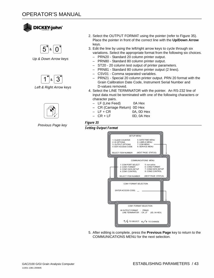
OPERATOR’S MANUAL
2. Select the OUTPUT FORMAT using the pointer (refer to Figure 35). Place the pointer in front of the correct line with the Up/Down Arrow keys.
3. Edit the line by using the left/right arrow keys to cycle through six variations. Select the appropriate format from the following six choices.– PRN20 - Standard 20 column printer output. – PRN80 - Standard 80 column printer output. – ST20 - 20 column test output of printer parameters. – PRN81 - Standard 80 column printer output (2 lines). – CSV01 - Comma separated variables. – PRN21 - Special 20 column printer output. PRN 20 format with the
Grain Calibration Date Code, Instrument Serial Number and D-values removed.
4. Select the LINE TERMINATOR with the pointer. An RS-232 line of input data must be terminated with one of the following characters or character pairs. – LF (Line Feed) 0A Hex – CR (Carriage Return) 0D Hex – LF + CR 0A, 0D Hex – CR + LF 0D, 0A Hex
Figure 35Setting Output Format
5. After editing is complete, press the Previous Page key to return to the COMMUNICATIONS MENU for the next selection.
5 0&
1 3&
SELECT ITEM NUMBER (NEXT PAGE: STATUS)
ENTER ACCESS CODE: __
COM1 FORMAT SELECTION
OUTPUT FORMAT : PRN20LINE TERMINATOR : CR, LF (0D, 0A HEX)
TO SELECT,
SETUP MENU
1: CLEAR COUNTER2: ID OPTIONS3: OUTPUT OPTIONS4: EDIT ACCESS CODE
5: DATE/TIME MENU6: LABELS MENU7: COM MENU8: SERVICE MENU
COMMUNICATIONS MENU
COM1 FORMAT SELECTION
1: COM PORT SELECT2: COM1 FORMAT3: COM1 DATA SETUP4: COM1 CONTROL
5: non-active6: COM2 FORMAT7: COM2 DATA SETUP8: COM2 CONTROL
TO CHANGE
SELECT ITEM NUMBER (NEXT PAGE: STATUS)
Up & Down Arrow keys
Left & Right Arrow keys
Previous Page key
GAC2100 G/GI Grain Analysis Computer11001-1381-200605
ESTABLISHING PARAMETERS / 43
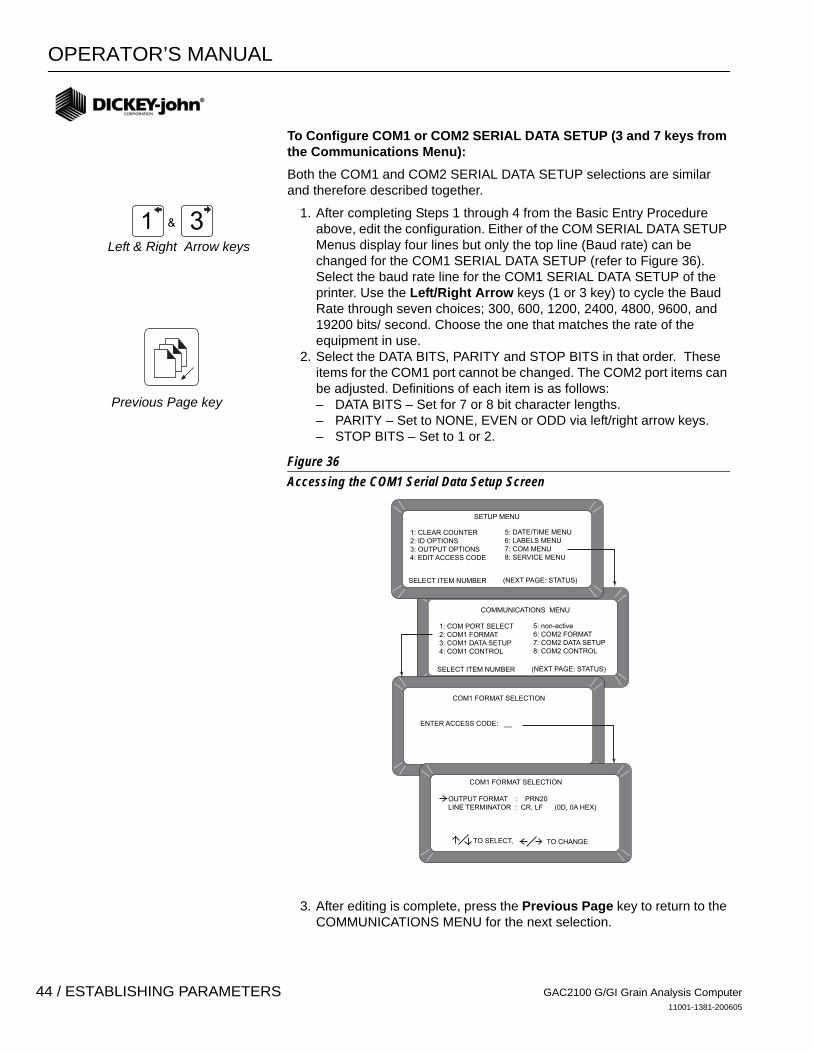
OPERATOR’S MANUAL
To Configure COM1 or COM2 SERIAL DATA SETUP (3 and 7 keys from the Communications Menu):
Both the COM1 and COM2 SERIAL DATA SETUP selections are similar and therefore described together.
1. After completing Steps 1 through 4 from the Basic Entry Procedure above, edit the configuration. Either of the COM SERIAL DATA SETUP Menus display four lines but only the top line (Baud rate) can be changed for the COM1 SERIAL DATA SETUP (refer to Figure 36). Select the baud rate line for the COM1 SERIAL DATA SETUP of the printer. Use the Left/Right Arrow keys (1 or 3 key) to cycle the Baud Rate through seven choices; 300, 600, 1200, 2400, 4800, 9600, and 19200 bits/ second. Choose the one that matches the rate of the equipment in use.
2. Select the DATA BITS, PARITY and STOP BITS in that order. These items for the COM1 port cannot be changed. The COM2 port items can be adjusted. Definitions of each item is as follows: – DATA BITS – Set for 7 or 8 bit character lengths. – PARITY – Set to NONE, EVEN or ODD via left/right arrow keys. – STOP BITS – Set to 1 or 2.
Figure 36Accessing the COM1 Serial Data Setup Screen
3. After editing is complete, press the Previous Page key to return to the COMMUNICATIONS MENU for the next selection.
1 3&
SELECT ITEM NUMBER (NEXT PAGE: STATUS)
ENTER ACCESS CODE: __
COM1 FORMAT SELECTION
OUTPUT FORMAT : PRN20LINE TERMINATOR : CR, LF (0D, 0A HEX)
TO SELECT,
SETUP MENU
1: CLEAR COUNTER2: ID OPTIONS3: OUTPUT OPTIONS4: EDIT ACCESS CODE
5: DATE/TIME MENU6: LABELS MENU7: COM MENU8: SERVICE MENU
COMMUNICATIONS MENU
COM1 FORMAT SELECTION
1: COM PORT SELECT2: COM1 FORMAT3: COM1 DATA SETUP4: COM1 CONTROL
5: non-active6: COM2 FORMAT7: COM2 DATA SETUP8: COM2 CONTROL
TO CHANGE
SELECT ITEM NUMBER (NEXT PAGE: STATUS)
Previous Page key
Left & Right Arrow keys
GAC2100 G/GI Grain Analysis Computer11001-1381-200605
44 / ESTABLISHING PARAMETERS
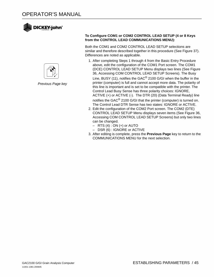
OPERATOR’S MANUAL
To Configure COM1 or COM2 CONTROL LEAD SETUP (4 or 8 Keys from the CONTROL LEAD COMMUNICATIONS MENU):
Both the COM1 and COM2 CONTROL LEAD SETUP selections are similar and therefore described together in this procedure (See Figure 37). Differences are noted as applicable.
1. After completing Steps 1 through 4 from the Basic Entry Procedure above, edit the configuration of the COM1 Port screen. The COM1 (DCE) CONTROL LEAD SETUP Menu displays two lines (See Figure 36, Accessing COM CONTROL LEAD SETUP Screens). The Busy Line, BUSY (11), notifies the GAC® 2100 G/GI when the buffer in the printer (computer) is full and cannot accept more data. The polarity of this line is important and is set to be compatible with the printer. The Control Lead Busy Sense has three polarity choices: IGNORE, ACTIVE (+) or ACTIVE (-). The DTR (20) (Data Terminal Ready) line notifies the GAC® 2100 G/GI that the printer (computer) is turned on. The Control Lead DTR Sense has two states: IGNORE or ACTIVE.
2. Edit the configuration of the COM2 Port screen. The COM2 (DTE) CONTROL LEAD SETUP Menu displays seven items (See Figure 36, Accessing COM CONTROL LEAD SETUP Screens) but only two lines can be changed. – RTS (4) : ON (+) or AUTO – DSR (6) : IGNORE or ACTIVE
3. After editing is complete, press the Previous Page key to return to the COMMUNICATIONS MENU for the next selection.
Previous Page key
GAC2100 G/GI Grain Analysis Computer11001-1381-200605
ESTABLISHING PARAMETERS / 45

OPERATOR’S MANUAL
Figure 37Accessing COM Control Lead Setup Screens
Figure 38Common Acronym Definitions
SELECT ITEM NUMBER (NEXT PAGE: STATUS)
ENTER ACCESS CODE: __
COM1 (DCE) CONTROL LEAD SETUP
BUSY (11) : IGNOREDTR (20) : ACTIVE
TO SELECT,
SETUP MENU
1: CLEAR COUNTER2: ID OPTIONS3: OUTPUT OPTIONS4: EDIT ACCESS CODE
5: DATE/TIME MENU6: LABELS MENU7: COM MENU8: SERVICE MENU
COMMUNICATIONS MENU
COM1 (DCE) CONTROL LEAD SETUP
1: COM PORT SELECT2: COM1 FORMAT3: COM1 DATA SETUP4: COM1 CONTROL
5: non-active6: COM2 FORMAT7: COM2 DATA SETUP8: COM2 CONTROL
TO CHANGE
SELECT ITEM NUMBER (NEXT PAGE: STATUS)
COM2 (DTE) CONTROL LEAD SETUP
MODE) : TRANSMIT ONLY
RTS (4) : ON (+) RLSD (8) : IGNORE
CTS (5) : ACTIVE DTR (20) : ON (+)
DSR (6) : IGNORE RI (22) : IGNORE
TO SELECT, TO CHANGE
OR
COM1PORTSCREEN
COM2
PORT
SCREEN
BUSY – Line busy DTR – Data Terminal ReadyCTS – Clear To Send RI – Ring IndicatorDCE – Data Communications RLSD – Receive Line Signal Equipment DetectDSR – Data Set Ready RTS – Request To SendDTE – Data Terminal RxD – Receive Data Equipment TxD – Transmit Data
GAC2100 G/GI Grain Analysis Computer11001-1381-200605
46 / ESTABLISHING PARAMETERS

OPERATOR’S MANUAL
Nonactive (5 Key from COMMUNICATIONS MENU)
The nonactive selection (refer to Figure 33) has no function and only emitsa long beep when pressed. No other action results.
USING THE SERVICE MENU (8 KEY) The SERVICE MENU contains individual unit calibration constants and is accessed by DICKEY-john trained and equipped service personnel.
GAC2100 G/GI Grain Analysis Computer11001-1381-200605
ESTABLISHING PARAMETERS / 47

OPERATOR’S MANUAL
GAC2100 G/GI Grain Analysis Computer11001-1381-200605
48 / ESTABLISHING PARAMETERS

OPERATOR’S MANUAL
TESTING UNIT PERFORMANCE
The TESTS MENU displays diagnostic tests and status information for operating values. The information is useful to technicians for overall performance evaluations and isolating problems. During normal operation, these are not generally referenced. However, problem identification can be assisted by reviewing certain values occasionally and observing changes. Most values cannot be edited but the contents can be printed for records. Also, while viewing the Factory Modes, earlier encountered errors stored in memory can be printed.
To access the TESTS MENU, press the 5 Key from the MAIN menu. The TESTS MENU appears showing eight choices as shown in Figure 39.
NONACTIVE KEYS The 1 and 4 key selections are nonactive and have no function assigned. Pressing either key will only result in a audible beep. (Refer to Figure 39).
Figure 39Entering the Tests Menu
MAIN MENU
1: MEASURE MOISTURE 3: CALIBRATION MENU2: SELECT GRAIN 4: SETUP MENU 5: TESTS MENU
SELECT ITEM NUMBER (NEXT PAGE: STATUS)
TESTS MENU
1: non-active2: COM13: COM2 TRANSMIT4: non-active
SELECT ITEM NUMBER (NEXT PAGE: STATUS)
5: DISPLAY6: DIAGNOSTIC MODE7: TEST NETWORK MODE8: PARAMETERS MENU
Performsno function
Performsno function
Displays allavailable characters
Showsconfigurationof COM1 Port
Showsconfiguration
of COM2 TRANSMIT Port
Accesses unittest information
Used fortroubleshooting
Allows viewingof system parameters
GAC2100 G/GI Grain Analysis Computer11001-1381-200605
TESTING UNIT PERFORMANCE / 49
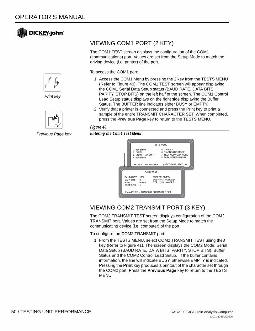
OPERATOR’S MANUAL
VIEWING COM1 PORT (2 KEY)The COM1 TEST screen displays the configuration of the COM1 (communications) port. Values are set from the Setup Mode to match the driving device (i.e. printer) of the port.
To access the COM1 port:
1. Access the COM1 Menu by pressing the 2 key from the TESTS MENU (Refer to Figure 40). The COM1 TEST screen will appear displaying the COM1 Serial Data Setup status (BAUD RATE, DATA BITS, PARITY, STOP BITS) on the left half of the screen. The COM1 Control Lead Setup status displays on the right side displaying the Buffer Status. The BUFFER line indicates either BUSY or EMPTY.
2. Verify that a printer is connected and press the Print key to print a sample of the entire TRANSMIT CHARACTER SET. When completed, press the Previous Page key to return to the TESTS MENU.
Figure 40Entering the Com1 Test Menu
VIEWING COM2 TRANSMIT PORT (3 KEY) The COM2 TRANSMIT TEST screen displays configuration of the COM2 TRANSMIT port. Values are set from the Setup Mode to match the communicating device (i.e. computer) of the port.
To configure the COM2 TRANSMIT port. 1. From the TESTS MENU, select COM2 TRANSMIT TEST using the3
key (Refer to Figure 41). The screen displays the COM2 Mode, Serial Data Setup (BAUD RATE, DATA BITS, PARITY, STOP BITS), Buffer Status and the COM2 Control Lead Setup. If the buffer contains information, the line will indicate BUSY, otherwise EMPTY is indicated. Pressing the Print key produces a printout of the character set through the COM2 port. Press the Previous Page key to return to the TESTS MENU.
TESTS MENU
1: non-active2: COM13: COM2 TRANSMIT4: non-active
SELECT ITEM NUMBER (NEXT PAGE: STATUS)
5: DISPLAY6: DIAGNOSTIC MODE7: TEST NETWORK MODE8: PARAMETERS MENU
COM1 TEST
BAUD RATE : 1200DATA BITS : 8PARTY : NONESTOP BITS : 1
Press PRINT to TRANSMIT CHARACTER SET
BUFFER: EMPTYBUSY (11): ACTIVE (+)DTR (20): IGNORE
Previous Page key
Print key
GAC2100 G/GI Grain Analysis Computer11001-1381-200605
50 / TESTING UNIT PERFORMANCE
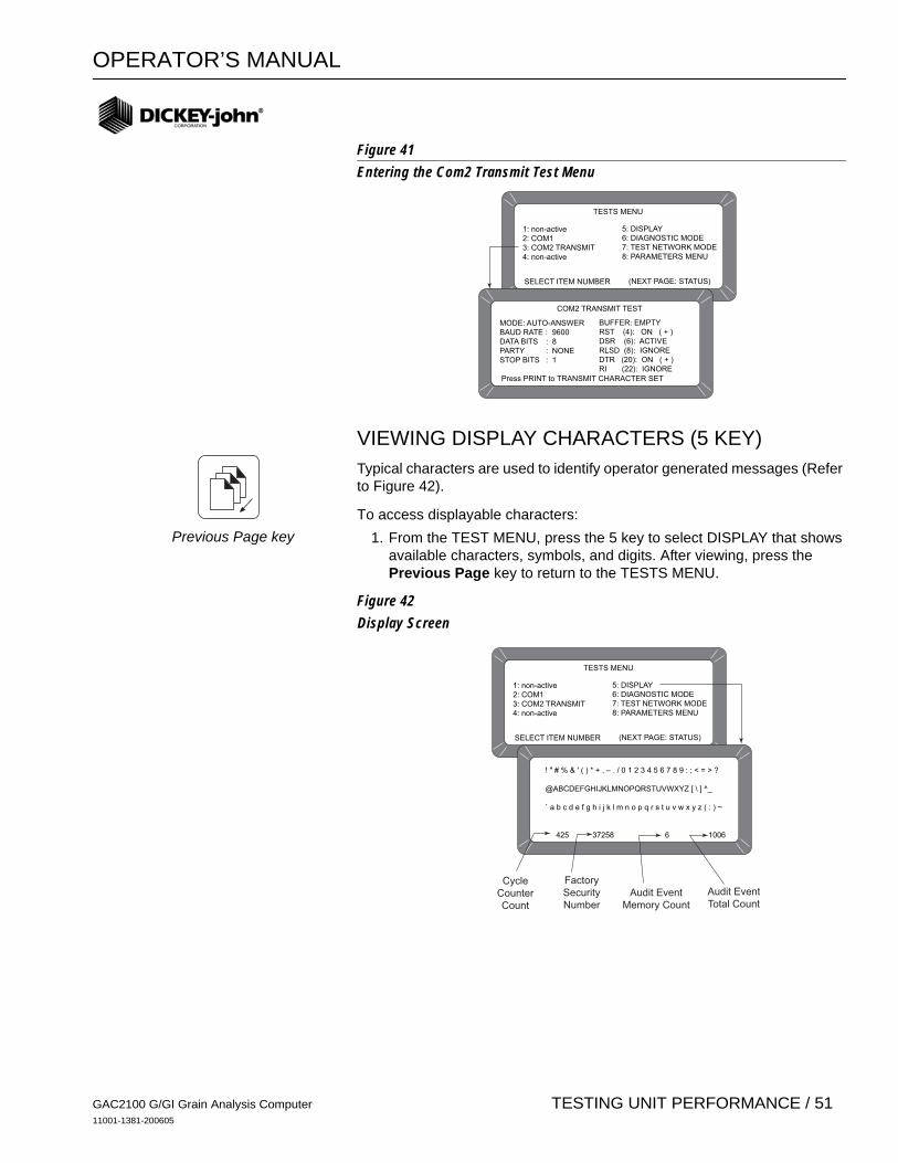
OPERATOR’S MANUAL
Figure 41Entering the Com2 Transmit Test Menu
VIEWING DISPLAY CHARACTERS (5 KEY) Typical characters are used to identify operator generated messages (Refer to Figure 42).
To access displayable characters: 1. From the TEST MENU, press the 5 key to select DISPLAY that shows
available characters, symbols, and digits. After viewing, press the Previous Page key to return to the TESTS MENU.
Figure 42Display Screen
TESTS MENU
1: non-active2: COM13: COM2 TRANSMIT4: non-active
SELECT ITEM NUMBER (NEXT PAGE: STATUS)
5: DISPLAY6: DIAGNOSTIC MODE7: TEST NETWORK MODE8: PARAMETERS MENU
COM2 TRANSMIT TEST
MODE: AUTO-ANSWERBAUD RATE : 9600DATA BITS : 8PARTY : NONESTOP BITS : 1
Press PRINT to TRANSMIT CHARACTER SET
BUFFER: EMPTYRST (4): ON ( + ) DSR (6): ACTIVERLSD (8): IGNOREDTR (20): ON ( + )RI (22): IGNORE
TESTS MENU
1: non-active2: COM13: COM2 TRANSMIT4: non-active
SELECT ITEM NUMBER (NEXT PAGE: STATUS)
5: DISPLAY6: DIAGNOSTIC MODE7: TEST NETWORK MODE8: PARAMETERS MENU
! " # % & ' ( ) * + , – . / 0 1 2 3 4 5 6 7 8 9 : ; < = > ?
@ABCDEFGHIJKLMNOPQRSTUVWXYZ [ \ ] ^_
` a b c d e f g h i j k l m n o p q r s t u v w x y z ( : ) ~
425 37258 6 1006
CycleCounterCount
FactorySecurityNumber
Audit EventMemory Count
Audit EventTotal Count
Previous Page key
GAC2100 G/GI Grain Analysis Computer11001-1381-200605
TESTING UNIT PERFORMANCE / 51

OPERATOR’S MANUAL
VIEWING DIAGNOSTIC MODE (6 KEY) The Diagnostic Mode accesses unit operating values. Most of these readout values relate to the test cell circuitry.
To access Diagnostic details:
1. Press the 6 key to enter the DIAGNOSTIC MODE (Page 1). Two pages of information are available as shown in Figure 43.
2. Press the number key next to each selection, one key at a time. Each value calculates and appears next to the line title. If the printer is connected, a printout of each result is automatically printed (Refer to Figure 44 for page 1 printout and Figure 45 for page 2 printout).
The meaning of each line is as follows:
– 1: Vnull - null voltage from cell board. – 2: Vtemp - temperature diode voltage from cell board. – 3: Cwgt - counts from weight oscillator. – 4: Ce/f - ratio of empty cell weight oscillator counts to full cell weight
oscillator counts. When 4 key is pressed, item 3 blanks to recalculate. A message states PLEASE WAIT followed by PLACE WEIGHT ON CELL THEN PRESS ENTER. A test weight is placed on top of the test cell and then the Enter key is pressed. After a short wait, the results display.
– 5: SCD1 - D1 (conductivity) self-check - 379 ±20. When either the 5 or 6 key is pressed, these two items calculate.
– 6: SCD2 - D2 (capacitance) self-check- 2500 ±20. – 7: Temp - Computed cell temperature in degrees C.
Figure 43Diagnostic Mode Screens
3. Press the Next Page key to view Page 2 of the DIAGNOSTIC MODE. The display screen is divided into two columns; 5 kHz and 2 MHz (See Figure 43).
TESTS MENU
1: non-active2: COM13: COM2 TRANSMIT4: non-active
SELECT ITEM NUMBER (NEXT PAGE: STATUS)
5: DISPLAY
6: DIAGNOSTIC MODE
7: TEST NETWORK MODE
8: PARAMETERS MENU
DIAGNOSTIC MODE PAGE 1
1: Vnull 5: SCD12: Vtemp 6: SCD23: Cwgt 7: Temp4: Ce/f 8:
SELECT TEST NUMBER <more>
DIAGNOSTIC MODE PAGE 25 KHz (D1) 2 MHz (D2)
1: Vc 5: Vc2: Vc - Vn 6: Vc - Vn3: Vsc 7: Vsc4: Vsc - Vn 8: Vsc - Vn
SELECT TEST NUMBER
Enter key
Next Page key
GAC2100 G/GI Grain Analysis Computer11001-1381-200605
52 / TESTING UNIT PERFORMANCE

OPERATOR’S MANUAL
5 kHz (D1) – Left half of screen
1: Vc - Voltage of 5 kHz oscillator. 2: Vc-Vn - Voltage of 5 kHz oscillator minus null voltage. 3: Vsc- Voltage of 5 kHz oscillator with on-board testnetwork engaged.4: Vsc - Vn - Voltage of 5 kHz oscillator with the on-board test network engaged minus null voltage.
2 MHz (D2) – Right half of screen 5: Vc - Voltage of 2 MHz oscillator. 6: Vc - Vn - Voltage of 2 MHz oscillator minus null voltage. 7: Vsc - Voltage of 2 MHz oscillator with on-board testnetwork engaged.8: Vsc - Vn - Voltage of 2 MHz oscillator with on-board test network engaged minus null voltage.
When finished, press the Previous Page key two times to return to the TESTS MENU.
Figure 44Diagnostic Mode Page 1 Printout
Figure 45Diagnostic Mode Page 2 Printout
VNULL: 0,0496VTEMP: 1,1838CWGT: 38908CE/F: 1,05377S/N: 0261-2360SCD1: 378SCD2: 2499NEC: 0,04941KEC: 1,50218KSC: 1,22889MEC: 1,40597MSC: 0,43373
TEMP: 18,26
5 KHZ VC: 1,50245 KHZ VC-VN: 1,45285 KHZ VSC: 1,22915 KHZ VSC-VN: 1,17952 MHZ VC: 1,49432 MHZ VC-VN: 1,44462 MHZ VSC: 0,44162 MHZ VSC-VN: 0,3920
Previous Page key
GAC2100 G/GI Grain Analysis Computer11001-1381-200605
TESTING UNIT PERFORMANCE / 53

OPERATOR’S MANUAL
USING TEST NETWORK MODE (7 KEY)
This mode is used by trained authorized personnel in troubleshooting. The screens and printout are shown for reference only.
To Access the TEST NETWORK MODE:
1. Press the 7 key - TEST NETWORK MODE (See Figure 46). The message PLEASE WAIT will appear followed by the PRESS LOAD TO BEGIN.
2. Press the Load key to start the measuring cycle. When the test completes, the results display and automatically print if a printer is connected (See Figure 47). Load key
GAC2100 G/GI Grain Analysis Computer11001-1381-200605
54 / TESTING UNIT PERFORMANCE
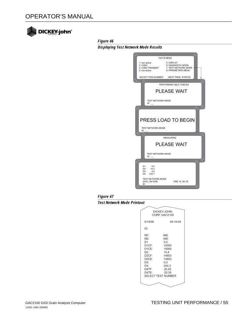
OPERATOR’S MANUAL
Figure 46Displaying Test Network Mode Results
Figure 47Test Network Mode Printout
TESTS MENU
1: non-active2: COM13: COM2 TRANSMIT4: non-active
SELECT ITEM NUMBER (NEXT PAGE: STATUS)
5: DISPLAY6: DIAGNOSTIC MODE7: TEST NETWORK MODE8: PARAMETERS MENU
PERFORMING SELF CHECKS
PLEASE WAIT
TEST NETWORK MODEID: __
PRESS LOAD TO BEGIN
TEST NETWORK MODEID: __
MEASURING
PLEASE WAIT
TEST NETWORK MODEID: __
D1: 0.0D2: 14.3D3: 0.0D4: 222.7
TEST NETWORK MODEDATE: 09/15/96 TIME 15: 38: 53ID:
DICKEY-JOHN,CORP. GAC2100
5/18/96 09:18:59
ID:
NF: 490NE: 490D1 0,0D1CF: 15000D1CE: 15000D2: 14,4D2CF: 14853D2CE: 14853D3: 0,0D4: 204,3D4TF: 20,43D4TE: 20,39SELECT TEST NUMBER
GAC2100 G/GI Grain Analysis Computer11001-1381-200605
TESTING UNIT PERFORMANCE / 55

OPERATOR’S MANUAL
VIEWING/PRINTING PARAMETERS (8 KEY)The PARAMETERS MENU (8 key) operates similar to the SERVICE MENU, located in the SETUP MENU. The major difference is the inability to edit values on these screens. However, the VIEW FACTORY MODE screen is useful in viewing the number of currently stored errors in memory. To view the PARAMETERS MENU:
1. Select the PARAMETERS MENU by pressing the 8 key from the TESTS MENU (See Figure 48). This menu allows the operator to view the unit parameters.
2. To print the values, select any menu and press the Print key. A printout of all the screens results (See Figure 49). Item 6 also prints all stored errors.
3. When finished viewing any screen, press the Previous Page key to return to the TESTS MENU.
Print key
Previous Page key
GAC2100 G/GI Grain Analysis Computer11001-1381-200605
56 / TESTING UNIT PERFORMANCE
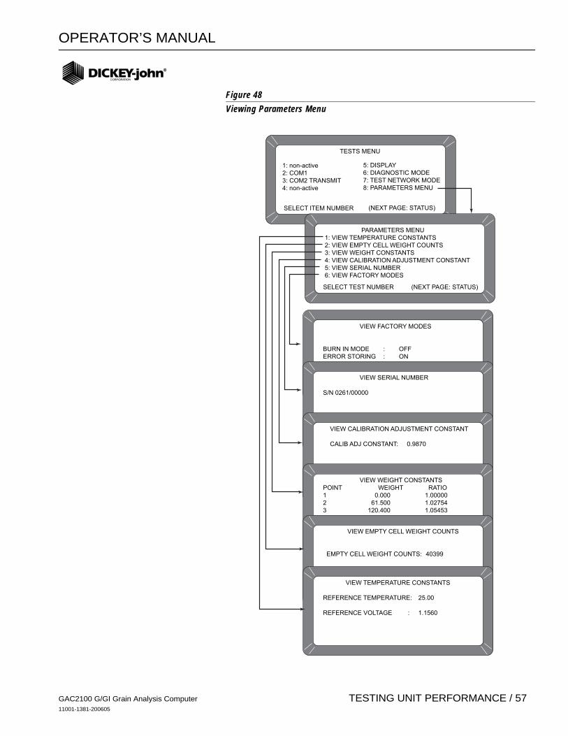
OPERATOR’S MANUAL
Figure 48Viewing Parameters Menu
TESTS MENU
1: non-active2: COM13: COM2 TRANSMIT4: non-active
SELECT ITEM NUMBER (NEXT PAGE: STATUS)
5: DISPLAY6: DIAGNOSTIC MODE7: TEST NETWORK MODE8: PARAMETERS MENU
PARAMETERS MENU1: VIEW TEMPERATURE CONSTANTS2: VIEW EMPTY CELL WEIGHT COUNTS3: VIEW WEIGHT CONSTANTS4: VIEW CALIBRATION ADJUSTMENT CONSTANT5: VIEW SERIAL NUMBER6: VIEW FACTORY MODES
SELECT TEST NUMBER (NEXT PAGE: STATUS)
VIEW FACTORY MODES
BURN IN MODE : OFFERROR STORING : ON
!! ERRORS HAVE BEEN STORED !! VIEW SERIAL NUMBER
S/N 0261/00000
VIEW CALIBRATION ADJUSTMENT CONSTANT
CALIB ADJ CONSTANT: 0.9870
VIEW WEIGHT CONSTANTSPOINT WEIGHT RATIO1 0.000 1.000002 61.500 1.027543 120.400 1.054534 181.800 1.083405 240.600 1.111796 300.300 1.14108 VIEW EMPTY CELL WEIGHT COUNTS
EMPTY CELL WEIGHT COUNTS: 40399
VIEW TEMPERATURE CONSTANTS
REFERENCE TEMPERATURE: 25.00
REFERENCE VOLTAGE : 1.1560
GAC2100 G/GI Grain Analysis Computer11001-1381-200605
TESTING UNIT PERFORMANCE / 57
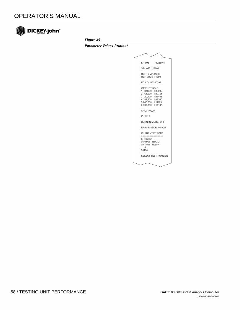
OPERATOR’S MANUAL
Figure 49Parameter Values Printout
5/18/96 09:59:46
S/N: 0261-23601
REF TEMP: 25,00REF VOLT: 1,1560
EC COUNT: 40399
WEIGHT TABLE:1 0,0000 1,000002 61,500 1,027543 120,400 1,054534 181,800 1,083405 240,600 1,111796 300,300 1,14108
CAC: 1,0000
IC: 1122
BURN IN MODE: OFF
ERROR STORING: ON
CURRENT ERRORS================ERROR 205/04/96 18:42:205/17/96 16:50:4 550134
SELECT TEST NUMBER
GAC2100 G/GI Grain Analysis Computer11001-1381-200605
58 / TESTING UNIT PERFORMANCE

OPERATOR’S MANUAL
OPERATOR MAINTENANCE
CELL CLEANING – DAILY 1. From the MAIN menu press the 5-key to display the TESTS menu.
Press the 6-key to display the DIAGNOSTICS menu. 2. At the DIAGNOSTICS menu, press the Load key. The hopper doors
open and remain open until Unload is pressed. 3. Use the brush supplied in the accessory kit to clean the inside of the
grain cell. 4. Slide the GAC® 2100 G/GI to the front of the worktable and remove the
grain drawer. Rach up inside and very carefully clean the strike - off arm spring.
Before performing Step 5, ensure that all fingers or other foreign objects are not in the cell area.
5. Press the Unload key. The cell will rotate 180 degrees to dump the residue from the cell cleaning procedure. The hopper doors close. Pressing the Previous Page key twice returns the display to the MAIN menu.
FUSE REPLACEMENT 1. Disconnect the line cord from the rear of the unit. Using a small blade
screwdriver or similar tool, remove the cover and fuse block assembly. 2. Replace the blown fuse with a 1 Amp Slo-Blo fuse (Fuse Size = 5mm
(0.197") dia. x 20 mm (0.787") long. 3. Reinstall fuse block assembly and cover.
Figure 50
Load key
Unload key
Previous Page key
GAC2100 G/GI Grain Analysis Computer11001-1381-200605
OPERATOR MAINTENANCE / 59

OPERATOR’S MANUAL
GAC2100 G/GI Grain Analysis Computer11001-1381-200605
60 / OPERATOR MAINTENANCE
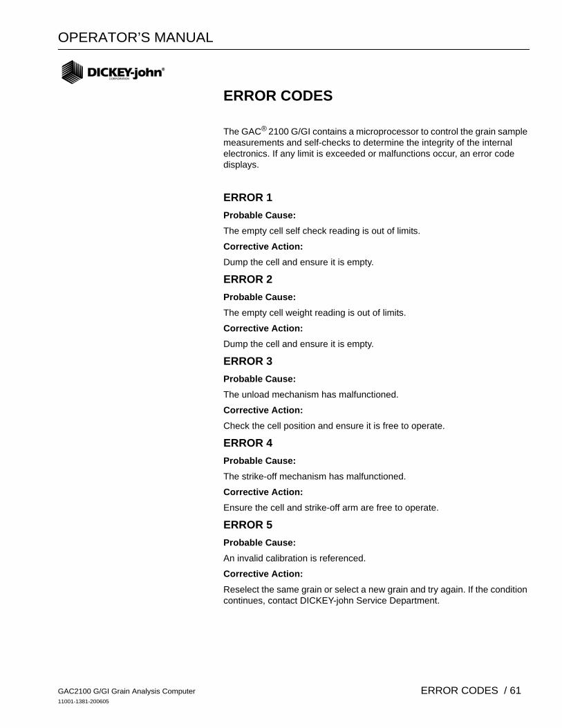
OPERATOR’S MANUAL
ERROR CODES
The GAC® 2100 G/GI contains a microprocessor to control the grain sample measurements and self-checks to determine the integrity of the internal electronics. If any limit is exceeded or malfunctions occur, an error code displays.
ERROR 1Probable Cause:The empty cell self check reading is out of limits.
Corrective Action:Dump the cell and ensure it is empty.
ERROR 2Probable Cause:The empty cell weight reading is out of limits.
Corrective Action:Dump the cell and ensure it is empty.
ERROR 3Probable Cause:The unload mechanism has malfunctioned.
Corrective Action:Check the cell position and ensure it is free to operate.
ERROR 4Probable Cause:The strike-off mechanism has malfunctioned.
Corrective Action:Ensure the cell and strike-off arm are free to operate.
ERROR 5Probable Cause:An invalid calibration is referenced.
Corrective Action:Reselect the same grain or select a new grain and try again. If the condition continues, contact DICKEY-john Service Department.
GAC2100 G/GI Grain Analysis Computer11001-1381-200605
ERROR CODES / 61
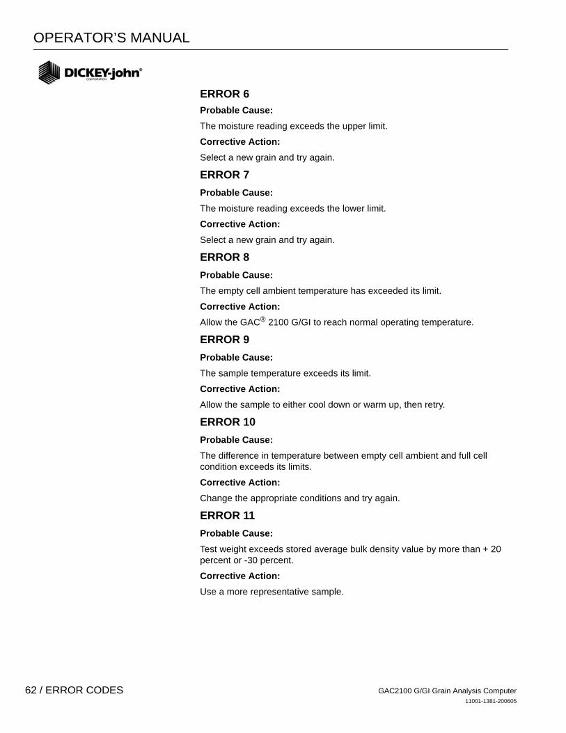
OPERATOR’S MANUAL
ERROR 6
Probable Cause:The moisture reading exceeds the upper limit.
Corrective Action:Select a new grain and try again.
ERROR 7Probable Cause:The moisture reading exceeds the lower limit.
Corrective Action:Select a new grain and try again.
ERROR 8Probable Cause:The empty cell ambient temperature has exceeded its limit.
Corrective Action:Allow the GAC® 2100 G/GI to reach normal operating temperature.
ERROR 9Probable Cause:The sample temperature exceeds its limit.
Corrective Action:Allow the sample to either cool down or warm up, then retry.
ERROR 10Probable Cause:The difference in temperature between empty cell ambient and full cell condition exceeds its limits.
Corrective Action:Change the appropriate conditions and try again.
ERROR 11Probable Cause:Test weight exceeds stored average bulk density value by more than + 20 percent or -30 percent.
Corrective Action:Use a more representative sample.
GAC2100 G/GI Grain Analysis Computer11001-1381-200605
62 / ERROR CODES

OPERATOR’S MANUAL
ERROR 12Probable Cause:A system memory error occurs.
Corrective Action:Turn the power off for at least five seconds and then back on again. If the condition continues, contact DICKEY-john Service Department.
ERROR 13Probable Cause:An on-board RAM memory error has occurred.
Corrective Action:Turn the power off for at least five seconds and then back on again. If the condition continues contact the supervisor.
ERROR 14 - NOT USED
ERROR 15
Probable Cause:The real time clock battery is faulty.
Corrective Action:Contact DICKEY-john Service Department.
GAC2100 G/GI Grain Analysis Computer11001-1381-200605
ERROR CODES / 63

OPERATOR’S MANUAL
GAC2100 G/GI Grain Analysis Computer11001-1381-200605
64 / ERROR CODES
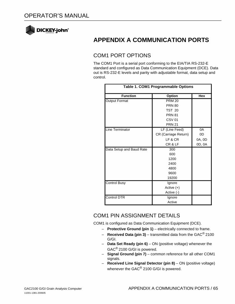
OPERATOR’S MANUAL
APPENDIX A COMMUNICATION PORTS
COM1 PORT OPTIONSThe COM1 Port is a serial port conforming to the EIA/TIA RS-232-E standard and configured as Data Communication Equipment (DCE). Data out is RS-232-E levels and parity with adjustable format, data setup and control.
COM1 PIN ASSIGNMENT DETAILS COM1 is configured as Data Communication Equipment (DCE).
– Protective Ground (pin 1) – electrically connected to frame.– Received Data (pin 3) – transmitted data from the GAC® 2100
G/GI.– Data Set Ready (pin 6) – ON (positive voltage) whenever the
GAC® 2100 G/GI is powered.– Signal Ground (pin 7) – common reference for all other COM1
signals.– Received Line Signal Detector (pin 8) – ON (positive voltage)
whenever the GAC® 2100 G/GI is powered.
Function Option HexPRM 20PRN 80TST 20PRN 81CSV 01PRN 21
LF (Line Feed) 0ACR (Carriage Return) 0D
LF & CR 0A, 0DCR & LF 0D, 0A
300600
1200240048009600
19200Ignore
Active (+)Active (-)
IgnoreActive
Control DTR
Data Setup and Baud Rate
Control Busy
Table 1. COM1 Programmable Options
Output Format
Line Terminator
GAC2100 G/GI Grain Analysis Computer11001-1381-200605
APPENDIX A COMMUNICATION PORTS / 65

OPERATOR’S MANUAL
– Busy (pin 11) – gates the transmission of data from the GAC® 2100 G/GI. The COM1 CONTROL LEAD SETUP can be configured ACTIVE (+), ACTIVE (–) or IGNORE. When the line is inactive, up to 2048 characters are buffered. If not connected, configure this line as IGNORE.
– Data Terminal Ready (pin 20) – indicates the connected device is not available. The COM1 CONTROL LEAD SETUP screen configures this line as ACTIVE or IGNORE. If configured ACTIVE, an OFF condition (negative or zero voltage) inhibits the transmission of data from the GAC® 2100 G/GI. Results display but not buffered for output on COM1. If not connected, this line should be configured as IGNORE.
Pin Number Designation Signal Name Direction1 AA Protective Ground NA3 BB (RxD) Received Data To Device6 CC (DSR) Data Set Ready To Device7 AB Signal Ground NA
8 CF (RLSD)Received Line Signal
Detector To Device11 Busy To GAC210020 CD (DTR) Data Terminal Ready To GAC2100
Table 2. COM1 Connector Pins Identification
GAC2100 G/GI Grain Analysis Computer11001-1381-200605
66 / APPENDIX A COMMUNICATION
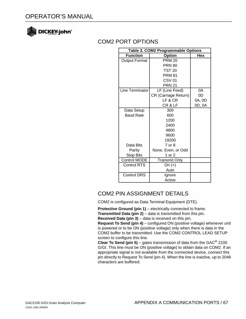
OPERATOR’S MANUAL
COM2 PORT OPTIONS
COM2 PIN ASSIGNMENT DETAILS COM2 is configured as Data Terminal Equipment (DTE).
Protective Ground (pin 1) – electrically connected to frame.Transmitted Data (pin 2) – data is transmitted from this pin.Received Data (pin 3) – data is received on this pin.Request To Send (pin 4) – configured ON (positive voltage) whenever unit is powered or to be ON (positive voltage) only when there is data in the COM2 buffer to be transmitted. Use the COM2 CONTROL LEAD SETUP screen to configure this line.Clear To Send (pin 5) – gates transmission of data from the GAC® 2100 G/GI. This line must be ON (positive voltage) to obtain data on COM2. If an appropriate signal is not available from the connected device, connect this pin directly to Request To Send (pin 4). When the line is inactive, up to 2048 characters are buffered.
Function Option HexOutput Format PRM 20
PRN 80TST 20PRM 81CSV 01PRN 21
Line Terminator LF (Line Feed) 0ACR (Carriage Return) 0D
LF & CR 0A, 0DCR & LF 0D, 0A
Data Setup 300Baud Rate 600
120024004800960019200
Data Bits 7 or 8Parity None, Even, or Odd
Stop Bits 1 or 2Control MODE Transmit OnlyControl RTS On (+)
AutoControl DRS Ignore
Active
Table 3. COM2 Programmable Options
GAC2100 G/GI Grain Analysis Computer11001-1381-200605
APPENDIX A COMMUNICATION PORTS / 67

OPERATOR’S MANUAL
Data Set Ready (pin 6) – notifies the GAC® 2100 G/GI that the connected device is not available. The COM2 CONTROL LEAD SETUP screen configures this line as active or ignored. If configured as active, an OFF condition (negative or zero voltage) inhibits the transmission of data from the GAC® 2100 G/GI. Results display but not buffered for output on COM2. If not connected, this line should be configured as ignored.Signal Ground (pin 7) – common ground reference for all other COM2 signals.Received Line Signal Detector (pin 8) – currently not used.Data Terminal Ready (pin 20) – ON (positive voltage) whenever the GAC® 2100 G/GI is powered.Ring Indicator (pin 22) – currently not used.
Pin Number Designation Signal Name Direction1 AA Protective Ground NA2 BA (TxD) Transmitted Data To Device3 BB (RxD) Received Data To GAC21004 CA (RTS) Request to Send To Device5 CB (CTS) Clear to Send To GAC21006 CC (DSR) Data Set Ready To GAC21007 AB Signal Ground NA
8 CF (RLSD)Received Line Signal Detector To GAC2100
20 CD (DTR) Data Terminal Ready To Device22 CE (R1) Ring Indicator To GAC2100
Table 4. COM1 Connector Pins Identification
GAC2100 G/GI Grain Analysis Computer11001-1381-200605
68 / APPENDIX A COMMUNICATION

For DICKEY-john Service Department,call 1-800-637-3302 in either the U.S.A. or Canada
Headquarters:5200 Dickey-john Road, Auburn, IL 62615TEL: 217-438-3371, FAX: 217-438-6012, WEB: www.dickey-john.comEurope:DICKEY-john Europe S.A., 165, boulevard de Valmy, 92706 - Columbes - FranceTEL: 33 (0) 1 41 19 21 80, FAX: 33 (0) 1 47 86 00 07
Dealers have the responsibility of calling to the attention of their customers the following warranty prior to acceptance of an order from their customer for any DICKEY-john product.
DICKEY-john® WARRANTYDICKEY-john warrants to the original purchaser for use that, if any part of the product
proves to be defective in material or workmanship within one year from date of originalinstallation, and is returned to DICKEY-john within 30 days after such defect is discovered,DICKEY-john will (at our option) either replace or repair said part. This warranty does notapply to damage resulting from misuse, neglect, accident, or improper installation ormaintenance. Said part will not be considered defective if it substantially fulfills theperformance expectations. THE FOREGOING WARRANTY IS EXCLUSIVE AND INLIEU OF ALL OTHER WARRANTIES OF MERCHANTABILITY, FITNESS FORPURPOSE, AND OF ANY OTHER TYPE, WHETHER EXPRESS OR IMPLIED.DICKEY-john neither assumes nor authorizes anyone to assume for it any other obligation orliability in connection with said part and will not be liable for consequential damages.Purchaser accepts these terms and warranty limitations unless the product is returned withinfifteen days for full refund of purchase price.
Copyright 2006 DICKEY-john CorporationSpecifications subject to change without notice