operators manual - rfi · directional watt meter operators manual. ... self-discharge cells brings...
TRANSCRIPT

3030
Directional Watt Meter
Operators Manual

Edition Notice !
This publication applies to:
COMM-connect A/S type 3030 Directional Watt Meter
Hardware release “1“
Software release 02.00.07
Copyright©2013-14
All rights reserved to:
COMM-connect A/S,
Sigerslevostervej 11,
DK-3600 Frederikssund, Denmark.
2
Table of Contents
General Safety 4
General Information 4
Description 4
Operation modes 4
Battery and Charging 5
Warranty 5
Options 6
Connections 6
Operating 7
Front Panel 7
Power On/Off 8
Menu Button 8
Arrow Buttons 8
Normal Mode 9
RMS Mode 9
Peak Mode 10
P-Hold (Peak Hold) Mode 10
Contrast 10
Power OFF time 10
Auto/Fixed Frequency 10
RTL (Return Loss) setting 11
Backlight 11
Sensitivity 11
Making Measurements 12
Accessories 13
Specifications 14
Conversion Tables 15
Abbreviations 15
3

General Safety:
The 3030 Directional Watt Meter should only be used for its intended pur-pose and never be connected to cables carrying hazardous voltages.
When handling NiMh batteries great care should be observed preventing polarity reversal and short circuit as the batteries may explode or catch fire.
General Information.
Description:
The 3030 Directional Watt Meter is a versatile transmitter power analyzer
covering all major communication bands from 30MHz to 500MHz*. The
3030 Directional Watt Meter will measurement forward and reflected power
in the range from 1 Watt up to 100 Watts. The 3030 has a low resolution
frequency counter to show the operating frequency and for calibration table
look up. The 3030 Directional Watt Meter will calculate VSWR. The detec-
tion system will capture short transmitter pulses (20mS) and show frequency
in MHz. For longer transmitter periods the counter will show the frequency in
kHz. The 3030 Directional Watt Meter has peak and hold function to capture
power and frequency. Simple Menu navigation to change instrument set-
tings. The 3030 Directional Watt Meter instrument is small, handy and light
weight battery operated with more than 4 hours of continuous operation on
the internal rechargeable NiMh low self-discharge cells. The usage of low
self-discharge cells brings several advantages, as the unit will retain its
charge for more than a year, and will sustain over 1000 charge cycles
Operation modes:
The 3030 Directional Watt Meter is as default operated like a conventional
thru line watt meter with the addition of SWR calculation and frequency
counting.
4

Battery and Charging:
The 3030 Directional Watt Meter is powered by 3 NiMh Low Self-discharge
AAA cells giving the instrument >4 hours of continuous operation when fully
charged.
The charging is done by USB from a PC or from a supplied charger via the
supplied USB cable. Charging current is approximately 250mA and full
charge is reached after 9 Hours of charging. The Charge indicator is always
lit when connected to your PC or the charger. The charging is a constant
current charge and can be left connect without damage to the battery cells. If
for any reason the batteries are replaced please replace with the same type
& rating.
In the event that the instrument has run out of battery, when arriving at a
customer site, please charge the unit for approx. 5 mins and leave the
charger connected, before commencing measurement.
The instrument can be use stand alone with alkaline AAA cells but NEVER
connect to USB or charger with alkaline cells!!
Warranty:
The 3030 Directional Watt Meter has a 1 year total warranty covering parts and labor as long as the instrument has been used according to the instruc-tions in this manual, and has not been subject to any abuse. Warranty will cover the return shipment after repair.
5
Charge Indicator

Options :
Accessory Kit, this kit contains a Soft carrying bag, adaptors from the “N”
female on the instrument into “BNC” female, “TNC” Female, Mini “UHF”,
“FME” male and a 5Volt USB regulated Cigarette Lighter Charger.
Peli case Kit, with a strong box for holding adaptors, charger, a 5Volt USB
regulated Cigarette Lighter Charger, cables and manual etc. The adaptor
set is a high quality 4 set of adaptors from N female to connectors of your
choice. See page 13.
Connections:
Two female “N” type connectors for the connection to the Transmitter on the INPUT side and to the antenna cable or other Load on the LOAD side of the instrument.
USB B PC Charger only (No PC connection)
6

Test Connectors
Graphic Display
Icon Line
Keys
Charge indicator
Battery USB PC Signal No Signal
Icons
7
The Front Panel
Power ON/OFF
Backlight On/Off

Power On/Off
Pressing the ON/OFF button firmly will switch on the instrument.
A welcome screen will appear like this:
The instrument will run for the duration of the auto power off period or until
ON/OFF is pressed firmly again.
Menu:
This button will display Menu :
Arrow buttons:
Use the arrow up and down buttons to select the menu line:
Compilation date
Product name
Software Version
Serial number
8

Menus continued:
Press Menu again to change setting!
Use Arrow buttons to change setting! And press ENTER to confirm change
and press ENTER again to return to measurement screen.
Measurement Modes:
In Normal mode the instrument will display Power and SWR when threshold
level is exceeded. The signal Icon will be lit. When the transmit signal disap-
pear so will the Power and SWR.
In RMS Mode the instrument will display Power and SWR When threshold
level is exceeded. The signal Icon will be lit. When the transmit signal disap-
pear the Power and SWR and Frequency will hold the reading and the hold
counter will run showing time from last signal was present. The No Signal
Icon is lit.
9
Menus continued:
The PEAK mode will find the maximum power level and decay the reading
slowly.
The P-Hold(Peak Hold) mode will find the maximum power level and hold
the reading.
The CONTRAST function can be used to adjust the LCD contrast.
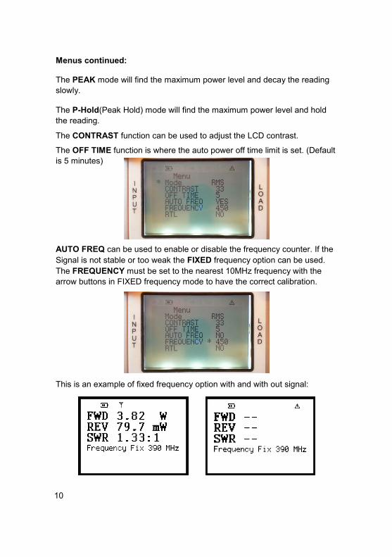
The OFF TIME function is where the auto power off time limit is set. (Default
is 5 minutes)
AUTO FREQ can be used to enable or disable the frequency counter. If the
Signal is not stable or too weak the FIXED frequency option can be used.
The FREQUENCY must be set to the nearest 10MHz frequency with the
arrow buttons in FIXED frequency mode to have the correct calibration.
This is an example of fixed frequency option with and with out signal:
10

Menus continued.
RTL:
Switches between displaying SWR and Return Loss as the 3rd measurement line.
Backlight:
The Backlight can be toggled on and off by the UP Arrow (see page 7)
All the menu setting can be combined in any configuration.
♦ ♦ ♦ ♦ ♦ ♦ ♦
Sensitivity of The 3030 Directional Watt Meter:
There are two conditions that must be met in order for the instrument to give a
reliable measurement. The counter must be stable enough to measure in MHz
resolution for the calibration table lookup to work. The next condition to be met is
the Forward Power level must be large enough to give a reliable SWR calculation.
In the figure below is a typical sensitivity plotted during automatic calibration of the
instrument.
11

Making Measurements General Setup: The 3030 Directional Watt Meter is a directional coupler in line Watt meter. The 3030 Directional Watt Meter is to be inserted between a Transmitter (Input) and an Antenna (Load) and will measure the transmitted power, the reflected power and calculate the Standing Wave Ratio. To make a calibrated measurement the frequency of the transmitter is counted and displayed on screen.
Connecting Transmitter and Antenna:
Observe the outmost care when connecting antennas via cables , as these
cables can be connected to transmitters and /or power sources! Make sure
the transmitter is turned off! Make sure you have chosen the antenna you
intend to test!!
Connection to high power transmitters 150+Watts and/or other sources can
destroy the instrument or cause hazardous electrical conditions.
When connecting to the “N” female connectors on the instrument make sure
you are using either “N” male antenna cable connectors or an appropriate
adaptor.
Please observe that the use of adapters and cable connections of poor
quality may influence the SWR and give higher readings than the actual
antenna SWR. Once the antenna an transmitter has been connected to the
instrument you switch on The 3030 Directional Watt Meter on and select
your choice in the menu. By observing the screen you can see transmitted
power, reflected power, the calculated SWR and the measured frequency.
Antennas are usually designed to have a SWR below a given value within
the band for which it is designed. As an example a TETRA 390MHz antenna
could have the following specifications: Range 380 - 400 MHz at SWR less
than 2.0:1 typical 1.5:1.
General hints
Always refer to antenna and transmitter manufacturers specification! Anten-
nas may have more than one resonance frequency! If the SWR value is
high or fluctuating the Antenna Cable may be broken or shorted!
Keep connectors clean and tight!
12

Optional accessories Kit: Automobile cigarette lighter regulated 5Volt USB charger. With lighter jack and USB plug. Coaxial adapters to fit “N” at the Test ports: 2 pcs. N male / FME male 2 pcs. N male / BNC female 2 pcs. N male / TNC female 2 pcs. N male / miniUHF female Soft canvas case ( order code: 3030_ACC ) : Hard Rugged and Watertight strong box ( order code: 3030_FULL ) :
13

Specifications:
Model Type: 3030, Directional Watt Meter
Application: Measurement of Power and SWR in a
50 Ω transmission line
Power Frequency range 30 – 500 MHz
Option: 30 - 1000 MHz
Counter Frequency range 30 to 1000 MHz, depending on option
Counter accuracy ±100 ppm (±50 kHz @ 500 MHz)
Measurement range Power 1 W to 100 W
Measurement range VSWR 1.0:1 < SWR < 9.9:1
Measurement Dynamic range > 24 dB (VSWR 1.15:1) @ 500 mW Forward and
above
Impedance Nom. 50 Ω
Directivity > 30 dB (30 - 500 MHz)
Mainline VSWR < 1.06:1 (30 - 500 MHz)
Tolerance on SWR reading 30-500 MHz ± 5% @ 1 W level
Operating temperature range +10° C-> + 40° C
Storage temperature range -30° C -> + 50° C
Connectors “N”-female RF Input and Load
USB B type for charge only.
Power supply 3 NiMH type AAA 1.2V 1 Ah rechargeable batteries
or 5 VDC from USB
Auto Power off For battery economy, 3030 automatically
turns off after user defined time. (5 minutes)
Capacity Fully charged: More than 4 hours continuously.
Colour Silver/blue
Width 92 mm
Depth 40 mm
Height 113 mm
Weight 400 gram (incl. Batteries)
EMC Complies with directive 89/336EEC as amended by
92/31EEC and 93/68/EEC
Standards Emissions: EN 61000-6-4: 2001
Immunity: EN 61000-6-2: 2005
14

Conversion table: Return Loss Reflection VSWR In dB Coefficient, r 1 0.891 17.4 2 0.794 8.72 3 0.707 5.85 4 0.631 4.42 5 0.562 3.57 6 0.501 3.01 7 0.447 2.61 8 0.398 2.32 9 0.355 2.10 10 0.316 1.92 12 0.251 1.67 14 0.199 1.50 16 0.158 1.38 18 0.126 1.29 20 0.100 1.22 25 0.056 1.12 30 0.032 1.07 35 0.018 1.04 40 0.010 1.02
Abbreviations SWR, VSWR (Voltage) Standing Wave Ratio RF Radio Frequency MHz Mega Hertz GaAs Gallium Arsenide MMIC Monolithic Microwave Integrated Circuit SMPS Switched Mode Power Supply GSM Global System for Mobile dBm deciBell referenced to 1 milli Watt dBd deciBell referenced to half wave dipole ppm parts per million LCD Liquid Crystal Display AC Alternating Current DC Direct Current NiMH Nickel Metal Hydride
15

The 3030 Directional Watt Meter
Operators Manual Version 1f