operator's manual lm601 landmark permanent blind
TRANSCRIPT

GAS/OILRATIO
50:1
Get parts online at www.HuntRiversEdge.com
Operator's Manual
LM601 Landmark™
Permanent Blind
P/N: 26742REV2: 02/06/18
© 2018 RETIAll Rights Reserved
Assembly Time 2-4 Hours
Check for parts online at www.HuntRiversEdge.com or call 800-450-EDGE (3343) M-F 8-52
Operator's Manual
Landmark™ Permanent Blind
CONTENTSIntroduction/Warnings ..................................................................................................................................................................................................................2
Frame Assembly Instructions ............................................................................................................................................................................................... 3-15
Skin Assembly Instructions .................................................................................................................................................................................................16-21
Ground Stake Instructions ........................................................................................................................................................................................................ 22
Warranty .......................................................................................................................................................................................................................................... 23
Parts Breakdown .....................................................................................................................................................................................................................24-25
Notes Pages ..............................................................................................................................................................................................................................26-27
INTRODUCTIONLandmark™ Permanent Blinds are engineered with you the hunter in mind. We appreciate your purchase of one of our world class products. Follow these few simple instructions and your blind will provide you many years of trouble-free pleasure. Instructions should be kept in a safe place and reviewed at least annually. If for any reason you have a problem with your product, DO NOT return to the retailer, contact the RETI customer service department at 800-450-3343 for assistance.
WARNING
Read, Understand and Follow all assembly, inspection and use instructions provided before each use. Failure to follow warnings and instructions could result in serious injury or death.
This product is for hunting purposes only! It is not to be used as a camping tent or for any other function.
Never allow children to play in this product without adult supervision. To do so could cause serious injury or death.
Never allow the material to cover your face. This material can cause suffocation and death if it is placed over face.
WARNING
Only use approved RETI parts. Failure to do so may result in serious injury or death!
WARNING
KEEP ALL FLAME AND HEAT SOURCES AWAY FROM THIS TENT FABRIC. This tent meets the flammability requirements of CPAI-84. The fabric may burn if left in continuous contact with any flame source. The application of any foreign substance to the tent fabric may render the flame-resistant properties ineffective.

Check for parts online at www.HuntRiversEdge.com or call 800-450-EDGE (3343) M-F 8-5 3
Operator's Manual
Landmark™ Permanent Blind
1. Open box, remove contents and organize all parts together according to their labels (four A1 parts together, four HUB1 parts together, etc.). This step greatly helps the ease of assembly.
2. Locate the four HUB1 corners, four of the six A1 poles and four of the six B1 poles and lay them out according to FIGURE 1.
3. Slide each A1 pole into the corresponding B1 pole so that the snap button secures both pieces together. Do this with the four sets of A1 and B1 poles. SEE FIGURE 1.
4. Slide the four assembled A1 and B1 poles into the four HUB1 corners so that the snap buttons secure the pieces together. You should now have the bottom tier frame of the blind assembled. SEE FIGURE 1.
FIGURE 1
FRAME ASSEMBLY INSTRUCTIONSTools needed – two 10mm wrenches
IMPORTANT ASSEMBLY TIP: Do not tighten any nut and bolt combinations completely until all parts are assembled together! Finger tighten plus one turn of a wrench only! This will temporarily hold the lock nut on the bolt while helping alignment of all parts! After all parts are assembled together, all nut & bolt combinations must be completely tightened.

Check for parts online at www.HuntRiversEdge.com or call 800-450-EDGE (3343) M-F 8-54
Operator's Manual
Landmark™ Permanent Blind
5. Slide the four C1 poles into the HUB1 corners so that the snap buttons secure pieces together. SEE FIGURE 2.
6. Attach the four HUB2 corners to C1 poles so that the snap buttons secure pieces together. PAY ATTENTION TO ORIENTATION OF THE HUB2 CORNERS! SEE FIGURE 2.
FIGURE 2

Check for parts online at www.HuntRiversEdge.com or call 800-450-EDGE (3343) M-F 8-5 5
Operator's Manual
Landmark™ Permanent Blind
7. Slide each of the three D2 poles into an E2 pole so that the snap button secures both pieces together. SEE FIGURE 3.
8. Slide the three assembled D2 and E2 poles into the HUB2 corners. These do not attach with snap buttons and will be secured together with hardware in a later step. SEE FIGURE 3.
FIGURE 3
Check for parts online at www.HuntRiversEdge.com or call 800-450-EDGE (3343) M-F 8-56
Operator's Manual
Landmark™ Permanent Blind
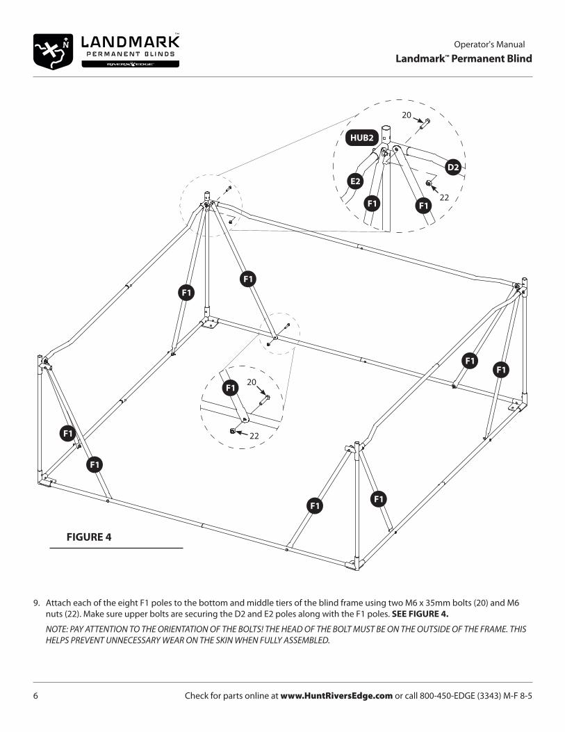
9. Attach each of the eight F1 poles to the bottom and middle tiers of the blind frame using two M6 x 35mm bolts (20) and M6 nuts (22). Make sure upper bolts are securing the D2 and E2 poles along with the F1 poles. SEE FIGURE 4.
NOTE: PAY ATTENTION TO THE ORIENTATION OF THE BOLTS! THE HEAD OF THE BOLT MUST BE ON THE OUTSIDE OF THE FRAME. THIS HELPS PREVENT UNNECESSARY WEAR ON THE SKIN WHEN FULLY ASSEMBLED.
FIGURE 4
20
22
20
22

Check for parts online at www.HuntRiversEdge.com or call 800-450-EDGE (3343) M-F 8-5 7
Operator's Manual
Landmark™ Permanent Blind
10. Slide two G1 poles into HUB2 corners on the door side of the blind so that the snap buttons secure pieces together. It is critical that the G1 poles are oriented such that snap buttons are facing each other and each through hole is located closer to the HUB3 corners than the HUB2 corners. SEE FIGURE 5.
11. Attach two HUB3 corners to the two G1 poles so that the snap buttons secure pieces together. PAY ATTENTION TO THE ORIENTATION OF HUB3! SEE FIGURE 5.
FIGURE 5
Through HoleCloser to HUB3
than HUB2
Through HoleCloser to HUB3
than HUB2

Check for parts online at www.HuntRiversEdge.com or call 800-450-EDGE (3343) M-F 8-58
Operator's Manual
Landmark™ Permanent Blind
12. Slide remaining two G1 poles into the other HUB2 corners so that snap button secures pieces together. It is critical that the G1 poles are oriented such that snap buttons are facing each other and each through hole is located closer to the HUB3 corners than the HUB2 corners. SEE FIGURE 6.
13. Attach remaining two HUB3 corners to the two G1 poles so that snap buttons secure pieces together. PAY ATTENTION TO THE ORIENTATION OF HUB3! SEE FIGURE 6.
FIGURE 6
Through HoleCloser to HUB3
than HUB2
Through HoleCloser to HUB3
than HUB2
Check for parts online at www.HuntRiversEdge.com or call 800-450-EDGE (3343) M-F 8-5 9
Operator's Manual
Landmark™ Permanent Blind
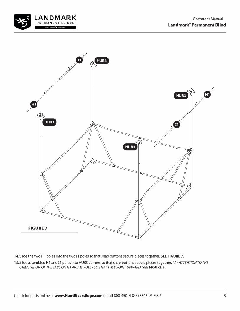
14. Slide the two H1 poles into the two I1 poles so that snap buttons secure pieces together. SEE FIGURE 7.
15. Slide assembled H1 and I1 poles into HUB3 corners so that snap buttons secure pieces together. PAY ATTENTION TO THE ORIENTATION OF THE TABS ON H1 AND I1 POLES SO THAT THEY POINT UPWARD. SEE FIGURE 7.
FIGURE 7

Check for parts online at www.HuntRiversEdge.com or call 800-450-EDGE (3343) M-F 8-510
Operator's Manual
Landmark™ Permanent Blind
16. Slide remaining two A1 poles into remaining two B1 poles so that snap buttons secure pieces together. SEE FIGURE 8.
17. Slide assembled A1 and B1 poles into HUB3 corner so that snap buttons secure pieces together. You should now have the top tier frame of the blind assembled. SEE FIGURE 8.
FIGURE 8
Check for parts online at www.HuntRiversEdge.com or call 800-450-EDGE (3343) M-F 8-5 11
Operator's Manual
Landmark™ Permanent Blind
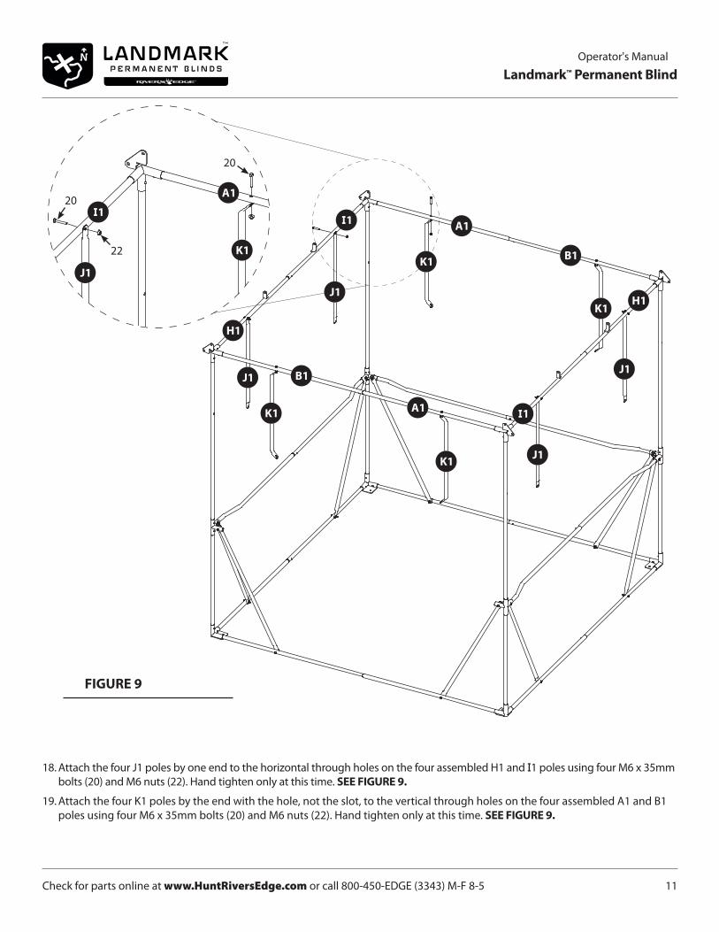
18. Attach the four J1 poles by one end to the horizontal through holes on the four assembled H1 and I1 poles using four M6 x 35mm bolts (20) and M6 nuts (22). Hand tighten only at this time. SEE FIGURE 9.
19. Attach the four K1 poles by the end with the hole, not the slot, to the vertical through holes on the four assembled A1 and B1 poles using four M6 x 35mm bolts (20) and M6 nuts (22). Hand tighten only at this time. SEE FIGURE 9.
FIGURE 9
20
22
20
Check for parts online at www.HuntRiversEdge.com or call 800-450-EDGE (3343) M-F 8-512
Operator's Manual
Landmark™ Permanent Blind
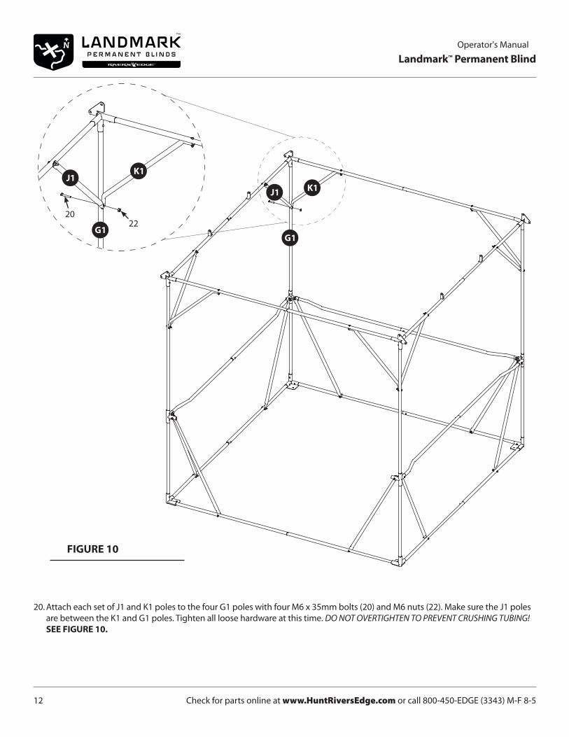
20. Attach each set of J1 and K1 poles to the four G1 poles with four M6 x 35mm bolts (20) and M6 nuts (22). Make sure the J1 poles are between the K1 and G1 poles. Tighten all loose hardware at this time. DO NOT OVERTIGHTEN TO PREVENT CRUSHING TUBING! SEE FIGURE 10.
FIGURE 10
2022

Check for parts online at www.HuntRiversEdge.com or call 800-450-EDGE (3343) M-F 8-5 13
Operator's Manual
Landmark™ Permanent Blind
21. Slide the four L1 poles into the four M1 poles and set aside. SEE FIGURE 11.
22. Slide the three N1 poles into the three O1 poles so that snap buttons secure pieces together and set aside.
23. Attached assembled L1 and M1 poles to one assembled N1 and O1 pole using the four M6 x 50mm bolts (19) and M6 nuts (22). SEE FIGURE 11.
NOTE: PAY ATTENTION TO THE ORIENTATION OF THE BOLTS! THE HEAD OF THE BOLT MUST BE ON THE TOP OF THE FRAME. THIS HELPS PREVENT UNNECESSARY WEAR ON THE SKIN WHEN FULLY ASSEMBLED.
FIGURE 11
19
22
Check for parts online at www.HuntRiversEdge.com or call 800-450-EDGE (3343) M-F 8-514
Operator's Manual
Landmark™ Permanent Blind
FIGURE 12
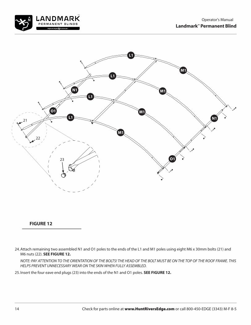
24. Attach remaining two assembled N1 and O1 poles to the ends of the L1 and M1 poles using eight M6 x 30mm bolts (21) and M6 nuts (22). SEE FIGURE 12.
NOTE: PAY ATTENTION TO THE ORIENTATION OF THE BOLTS! THE HEAD OF THE BOLT MUST BE ON THE TOP OF THE ROOF FRAME. THIS HELPS PREVENT UNNECESSARY WEAR ON THE SKIN WHEN FULLY ASSEMBLED.
25. Insert the four eave end plugs (23) into the ends of the N1 and O1 poles. SEE FIGURE 12.
21
22
23
Check for parts online at www.HuntRiversEdge.com or call 800-450-EDGE (3343) M-F 8-5 15
Operator's Manual
Landmark™ Permanent Blind
FIGURE 13
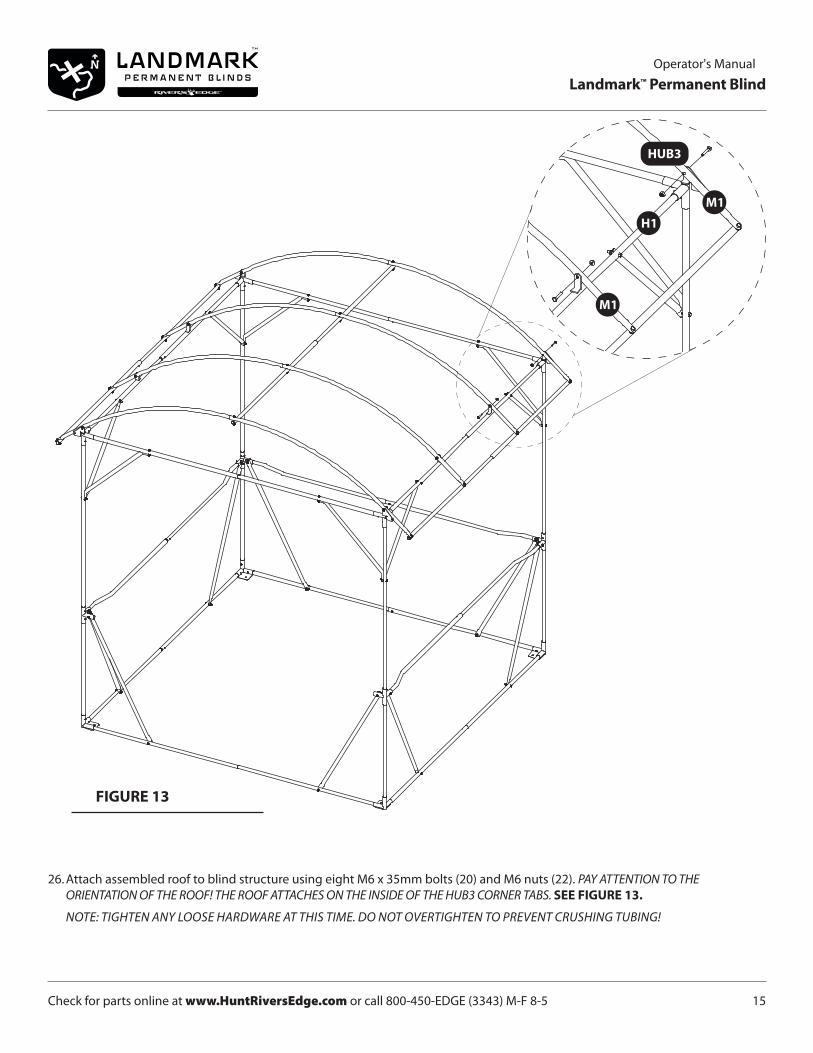
26. Attach assembled roof to blind structure using eight M6 x 35mm bolts (20) and M6 nuts (22). PAY ATTENTION TO THE ORIENTATION OF THE ROOF! THE ROOF ATTACHES ON THE INSIDE OF THE HUB3 CORNER TABS. SEE FIGURE 13.
NOTE: TIGHTEN ANY LOOSE HARDWARE AT THIS TIME. DO NOT OVERTIGHTEN TO PREVENT CRUSHING TUBING!
Check for parts online at www.HuntRiversEdge.com or call 800-450-EDGE (3343) M-F 8-516
Operator's Manual
Landmark™ Permanent Blind
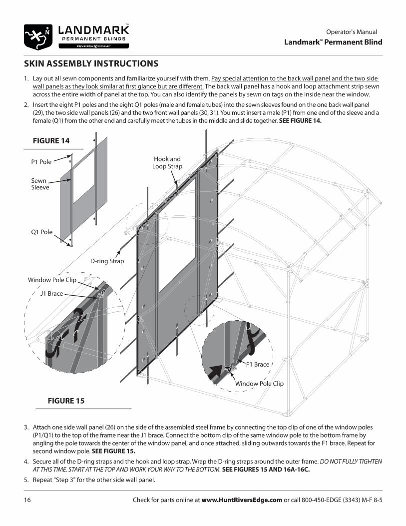
3. Attach one side wall panel (26) on the side of the assembled steel frame by connecting the top clip of one of the window poles (P1/Q1) to the top of the frame near the J1 brace. Connect the bottom clip of the same window pole to the bottom frame by angling the pole towards the center of the window panel, and once attached, sliding outwards towards the F1 brace. Repeat for second window pole. SEE FIGURE 15.
4. Secure all of the D-ring straps and the hook and loop strap. Wrap the D-ring straps around the outer frame. DO NOT FULLY TIGHTEN AT THIS TIME. START AT THE TOP AND WORK YOUR WAY TO THE BOTTOM. SEE FIGURES 15 AND 16A-16C.
5. Repeat "Step 3" for the other side wall panel.
SKIN ASSEMBLY INSTRUCTIONS1. Lay out all sewn components and familiarize yourself with them. Pay special attention to the back wall panel and the two side
wall panels as they look similar at first glance but are different. The back wall panel has a hook and loop attachment strip sewn across the entire width of panel at the top. You can also identify the panels by sewn on tags on the inside near the window.
2. Insert the eight P1 poles and the eight Q1 poles (male and female tubes) into the sewn sleeves found on the one back wall panel (29), the two side wall panels (26) and the two front wall panels (30, 31). You must insert a male (P1) from one end of the sleeve and a female (Q1) from the other end and carefully meet the tubes in the middle and slide together. SEE FIGURE 14.
FIGURE 15
D-ring Strap
Hook and Loop Strap
Window Pole Clip
J1 Brace
F1 Brace
Window Pole Clip
FIGURE 14
P1 Pole
Q1 Pole
Sewn Sleeve
Check for parts online at www.HuntRiversEdge.com or call 800-450-EDGE (3343) M-F 8-5 17
Operator's Manual
Landmark™ Permanent Blind
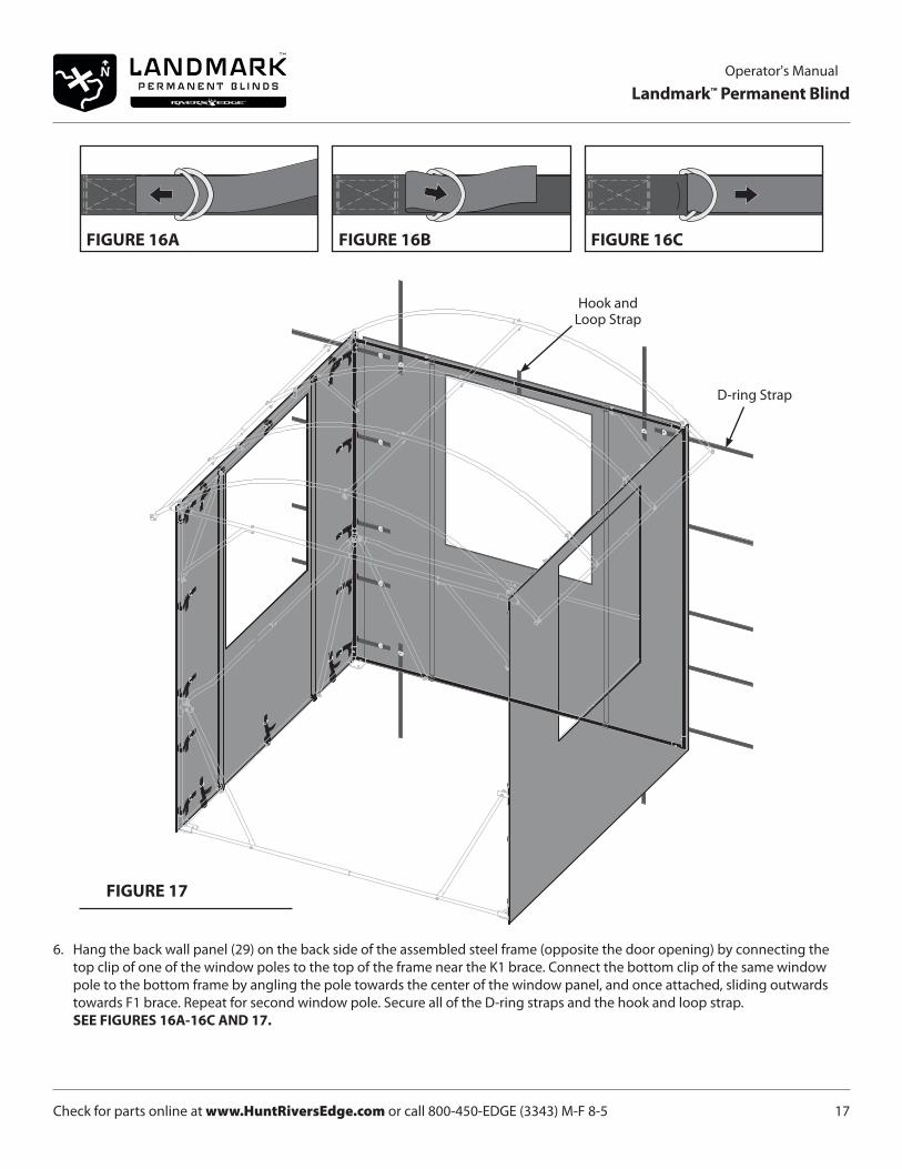
6. Hang the back wall panel (29) on the back side of the assembled steel frame (opposite the door opening) by connecting the top clip of one of the window poles to the top of the frame near the K1 brace. Connect the bottom clip of the same window pole to the bottom frame by angling the pole towards the center of the window panel, and once attached, sliding outwards towards F1 brace. Repeat for second window pole. Secure all of the D-ring straps and the hook and loop strap. SEE FIGURES 16A-16C AND 17.
FIGURE 16A FIGURE 16B FIGURE 16C
FIGURE 17
D-ring Strap
Hook and Loop Strap
Check for parts online at www.HuntRiversEdge.com or call 800-450-EDGE (3343) M-F 8-518
Operator's Manual
Landmark™ Permanent Blind
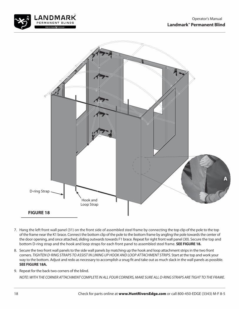
7. Hang the left front wall panel (31) on the front side of assembled steel frame by connecting the top clip of the pole to the top of the frame near the K1 brace. Connect the bottom clip of the pole to the bottom frame by angling the pole towards the center of the door opening, and once attached, sliding outwards towards F1 brace. Repeat for right front wall panel (30). Secure the top and bottom D-ring strap and the hook and loop straps for each front panel to assembled steel frame. SEE FIGURE 18.
8. Secure the two front wall panels to the side wall panels by matching up the hook and loop attachment strips in the two front corners. TIGHTEN D-RING STRAPS TO ASSIST IN LINING UP HOOK AND LOOP ATTACHMENT STRIPS. Start at the top and work your way to the bottom. Adjust and redo as necessary to accomplish a snug fit and take out as much slack in the wall panels as possible. SEE FIGURE 18A.
9. Repeat for the back two corners of the blind.
NOTE: WITH THE CORNER ATTACHMENT COMPLETE IN ALL FOUR CORNERS, MAKE SURE ALL D-RING STRAPS ARE TIGHT TO THE FRAME.
FIGURE 18
D-ring Strap
Hook and Loop Strap
A

Check for parts online at www.HuntRiversEdge.com or call 800-450-EDGE (3343) M-F 8-5 19
Operator's Manual
Landmark™ Permanent Blind
FIGURE 19
10. Drape the roof panel (25) over the assembled roof frame. Secure the hook and loop attachment strips on the front and the back of roof panel to the strips on the front and back wall panels. SEE FIGURE 19A.
NOTE: ADJUST AND REDO AS NECESSARY TO TAKE OUT AS MUCH SLACK IN THE FABRIC AS POSSIBLE.
11. Wrap the edge corner flaps of the roof panel around the eave corners of the frame assembly and secure with hook and loop attachment squares. SEE FIGURE 19B-C.
12. Pull the roof panel tight by wrapping D-ring straps around eave frame. Feed the long strap through both D-rings and back through to tighten. Refer back to FIGURES 16A-16C for strap routing.
A
B C

Check for parts online at www.HuntRiversEdge.com or call 800-450-EDGE (3343) M-F 8-520
Operator's Manual
Landmark™ Permanent Blind
FIGURE 20
13. Locate the three horizontal window panels with shooting rail sleeves (27) and the three S1 poles. Insert an S1 pole into the shooting rail sleeve on each window panel. SEE PARTS BREAKDOWN (Page 25).
14. Locate the other three horizontal window panels (28) and the six vertical window panels (35). NOTE: SET ASIDE THE TWO DOOR PANELS (34) FOR NOW. THEY ARE LONGER THAN THE HORIZONTAL WINDOW PANELS.
15. Attach a horizontal window panel with shooting rail (27) to one of the window openings by connecting the clips to the lower half of the window poles. MAKE SURE THE SHOOTING RAIL IS ON THE TOP. Attach a horizontal window panel (28) to the top half of the same window poles. SEE FIGURE 20.
NOTE: THE TETHER BUCKLE SHOULD BE LOCATED IN THE LOWER LEFT OF THE BOTTOM HORIZONTAL WINDOW PANEL WITH SHOOTING RAIL AND THE UPPER LEFT OF THE TOP HORIZONTAL WINDOW PANEL.
16. On the same window opening, attach two vertical window panels (35) by connecting the clips to the right and left sides of the top frame pole and mid frame pole. SEE FIGURE 21.
NOTE: THE TETHER BUCKLE SHOULD BE LOCATED ON THE TOP OF BOTH VERTICAL WINDOW PANELS.
17. Repeat Step 15-16 for the other two windows.
18. Attach the two door panels (34) by connecting the clips to the vertical poles of the two front wall panels. NOTE: THE TETHER BUCKLE SHOULD BE LOCATED IN THE LOWER RIGHT OF THE BOTTOM DOOR PANEL AND IN THE UPPER LEFT OF
THE UPPER DOOR PANEL. NOTE: SLIDE CLIPS OF LOWER DOOR PANEL DOWN AND SLIDE CLIPS OF UPPER DOOR PANEL UP TO CREATE DOOR OPENING.
WHEN IN USE, SLIDE TO WANTED GAP FOR USE AS FOURTH WINDOW.
FIGURE 21
Tether Buckle
Shooting Rail
Tether Buckle
ClipWindow Pole
Top Frame Pole
Clip
Tether Buckle
Mid Frame Pole
Check for parts online at www.HuntRiversEdge.com or call 800-450-EDGE (3343) M-F 8-5 21
Operator's Manual
Landmark™ Permanent Blind
FIGURE 22
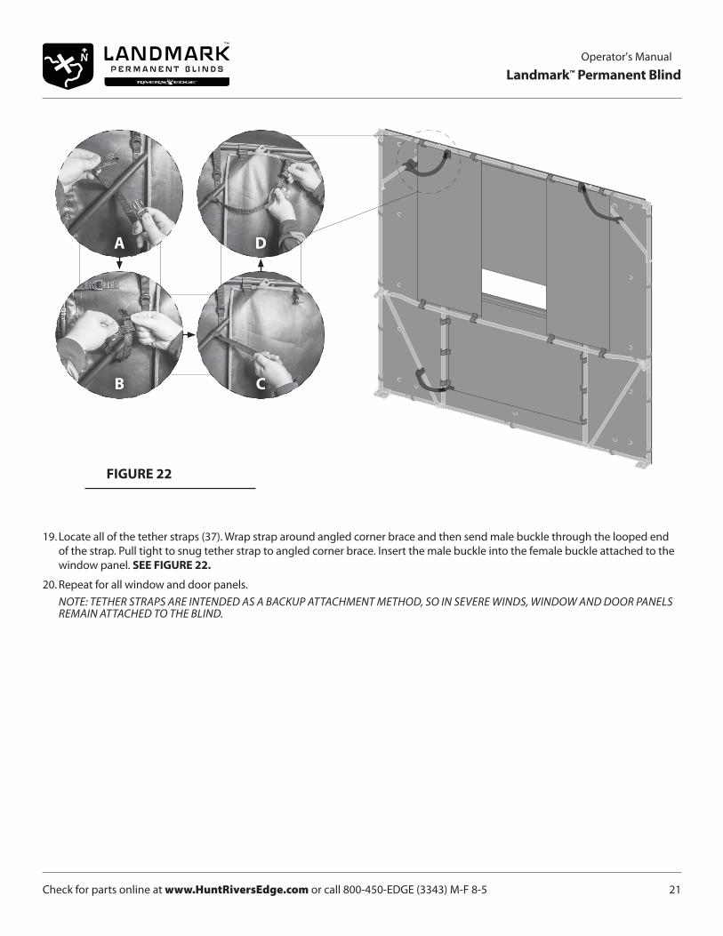
19. Locate all of the tether straps (37). Wrap strap around angled corner brace and then send male buckle through the looped end of the strap. Pull tight to snug tether strap to angled corner brace. Insert the male buckle into the female buckle attached to the window panel. SEE FIGURE 22.
20. Repeat for all window and door panels. NOTE: TETHER STRAPS ARE INTENDED AS A BACKUP ATTACHMENT METHOD, SO IN SEVERE WINDS, WINDOW AND DOOR PANELS
REMAIN ATTACHED TO THE BLIND.
A
B
D
C

Check for parts online at www.HuntRiversEdge.com or call 800-450-EDGE (3343) M-F 8-522
Operator's Manual
Landmark™ Permanent Blind
Corkscrew Stake
Sewn Strap
GROUND STAKE INSTRUCTIONS1. On the inside of the blind, screw corkscrew stake into ground near corner. SEE FIGURE 23.
2. Take loop end of a sewn strap and slide onto corkscrew stake. SEE FIGURE 23.
3. Wrap opposite end of sewn strap around closest D2 or E2 horizontal frame pole and feed end down through both D-rings.
4. Send end of sewn strap up and over the bottom D-ring and up and through the top D-ring.
5 Pull end of sewn strap tight to engage frame to ground stake.
6. Repeat steps for remaining three corkscrew stakes in the other three corners of the blind.
FIGURE 23

Check for parts online at www.HuntRiversEdge.com or call 800-450-EDGE (3343) M-F 8-5 23
Operator's Manual
Landmark™ Permanent Blind
ONE YEAR LIMITED WARRANTYRETI., warrants this product under a one-year limited warranty to be free from defects in materials or workmanship or both for a period not exceeding twelve consecutive months from the date of original purchase by the first retail consumer or commercial end user. “Consumer use” means personal recreational use by a retail consumer. “Commercial use” or “commercial application” means all other uses, including use for commercial, income producing or rental purposes. Once a product has experienced commercial use, it shall thereafter be considered as a commercial use product for purposes of this warranty. This warranty does not cover cracked windows, tent tears, or bent poles due to use in exteme weather conditions (i.e. hurricane force winds) or uses other than those listed in the owner’s manual. Damage that occurs to a unit due to improper anchoring is not covered under manufacturer warranty. This warranty applies to the original owner that provides a proof of purchase of the unit. The warranty is not transferable. The warranty period begins on the date of purchase by the first retail consumer or commercial end user, and continues for the twelve month consecutive period thereafter. Any unit used in a commercial application is covered for a period of 90 days after purchase. For the warranty to be valid, the product must be registered online at huntriversedge.com, within 30 days of purchase. RETI shall not be obligated to ship any repair or replacement product to any location outside of the United States of America or Canada.
This warranty applies only to products which have not been subjected to negligent use, misuse, uses other than those indicated in the product’s owner’s manual, alteration, accident, use of unauthorized parts, failure to perform periodic maintenance as specified in product’s owner’s manual, or normal wear and tear. There is no other expressed warranty. Implied warranties, including those of merchantability and fitness for a particular purpose, are limited to one year from purchase, or to the extent permitted by law. All other implied warranties are excluded. Liability for incidental or consequential damages are excluded to the extent exclusion is permitted by law. RETI does not assume, and does not authorize any other person to assume for us, any liability in connection with the sale of our products. To obtain warranty service, you must have prior approval by calling our Customer Service Department at 1-800-450-3343. RETI will at no charge, repair or replace, at their discretion, any defective part which satisfies all conditions stated above. RETI retains the right to change models, specifications and price without notice. RETI shall not be obligated to ship any repair or replacement product to any location outside of the United States of America or Canada.
If you choose to elevate this product to use above ground (on a tower type structure), only use RETI original designed structures to do so. *Using man-made structures or structures not manufactured by RETI will void your warranty and waive any and all claims for liability against the manufacturer RETI. If you choose to elevate this product on a RETI brand tower structure, the warranty listed in the tower structure manual will apply to this product in addition to the warranty statement in this owner's manual.
* Please see page 2 of this manual for additional related information and warnings.

Check for parts online at www.HuntRiversEdge.com or call 800-450-EDGE (3343) M-F 8-524
Operator's Manual
Landmark™ Permanent Blind
KEY # PART # DESCRIPTION QTY.
1 22864 BASE HUB "HUB1" 4
2 22930 HORIZONTAL SUPPORT FEMALE "B1" 6
3 22932 HORIZONTAL SUPPORT MALE "A1" 6
4 22934 LOWER VERTICAL SUPPORT "C1" 4
5 22868 MIDDLE HUB "HUB2" 4
6 26680 HORIZONTAL SUPPORT MALE BENT "D2" 3
7 26681 HORIZONTAL SUPPORT FEMALE BENT "E2" 3
8 22869 LOWER CROSS BRACE "F1" 8
9 22933 UPPER VERTICAL SUPPORT "G1" 4
10 22873 ROOF HUB "HUB3" 4
11 22876 ROOF MOUNT MALE "H1" 2
12 22878 ROOF MOUNT FEMALE "I1" 2
KEY # PART # DESCRIPTION QTY.
13 22879 UPPER CROSS BRACE "J1" 4
14 22880 CORNER CROSS BRACE "K1" 4
15 22881 ROOF TUBE MALE "L1" 4
16 22882 ROOF TUBE FEMALE "M1" 4
17 22935 ROOF SUPPORT MALE "N1" 3
18 22884 ROOF SUPPORT FEMALE "O1" 3
19 22334 M6 X 50MM BOLT 4
20 22947 M6 X 35MM BOLT 36
21 22588 M6 X 30MM BOLT 8
22 22946 M6 NUT 48
23 27168 ROUND END PLUG 19MM TUBING 4
PARTS BREAKDOWN
2
1413
20
720
3
161719
183101215
22
21
11
9
658
4
1
2
23
23

Check for parts online at www.HuntRiversEdge.com or call 800-450-EDGE (3343) M-F 8-5 25
Operator's Manual
Landmark™ Permanent Blind
KEY # PART # DESCRIPTION QTY.
24 23876 WINDOW RAIL TUBE "S1" 3
25 22891 SEWN ROOF PANEL 1
26 24932 SEWN SIDE PANEL 2
27 26696 SEWN LOWER HORIZ WINDOW PANEL 3
28 26695 SEWN UPPER HORIZ WINDOW PANEL 3
29 24933 SEWN BACK PANEL 1
30 25475 SEWN RIGHT FRONT PANEL 1
KEY # PART # DESCRIPTION QTY.
31 25474 SEWN LEFT FRONT PANEL 1
32 22887 DOOR TUBE FEMALE "Q1" 8
33 22889 DOOR TUBE MALE "P1" 8
34 26721 SEWN DOOR PANEL 2
35 26698 SEWN VERTICAL WINDOW PANEL 6
ITEMS NOT SHOWN
36 25163 TIE DOWN CORKSCREW STAKES KIT 1
37 26931 TETHER STRAP/BUCKLE MALE 14
PARTS BREAKDOWN
28
24
27
35
35 33
26
32
34
34
25
31
30
26
29

Check for parts online at www.HuntRiversEdge.com or call 800-450-EDGE (3343) M-F 8-526
Operator's Manual
Landmark™ Permanent Blind
NOTES
Check for parts online at www.HuntRiversEdge.com or call 800-450-EDGE (3343) M-F 8-5 27
Operator's Manual
Landmark™ Permanent Blind
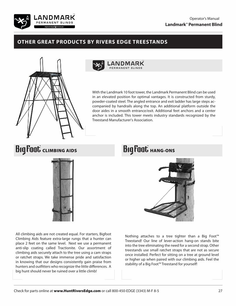
With the Landmark 10 foot tower, the Landmark Permanent Blind can be used in an elevated position for optimal vantages. It is constructed from sturdy, powder-coated steel. The angled entrance and exit ladder has large steps ac-companied by handrails along the top. An additional platform outside the door aides in a smooth entrance/exit. Additional feet anchors and a center anchor is included. This tower meets industry standards recognized by the Treestand Manufacturer's Association.
All climbing aids are not created equal. For starters, Bigfoot Climbing Aids feature extra-large rungs that a hunter can place 2 feet on the same level. Next we use a permanent anti-slip coating called Tractionite. Our assortment of climbing aids securely attach to the tree using a cam straps or ratchet straps. We take immense pride and satisfaction in knowing that our designs consistently gain praise from hunters and outfitters who recognize the little differences. A big hunt should never be ruined over a little climb!
CLIMBING AIDS
OTHER GREAT PRODUCTS BY RIVERS EDGE TREESTANDS
Nothing attaches to a tree tighter than a Big Foot™ Treestand! Our line of lever-action hang-on stands bite into the tree eliminating the need for a second strap. Other treestands use small ratchet straps that are not as secure once installed. Perfect for sitting on a tree at ground level or higher up when paired with our climbing aids. Feel the stability of a Big Foot™ Treestand for yourself!
HANG-ONS

*All weights, specifications and features are approximate and are subject to change without notice. Due to continuous product improvements, product images may not be exact. Warning labels in some product images may have been removed for photography purposes only. Props shown in photos not included. Some assembly may be required.
Rivers Edge® Treestands, Inc.
1160 Eighth Avenue, PO Box 755
Cumberland, WI 54829
Phone: 800-450-EDGE (3343)
Fax: 715-822-2124
www.HuntRiversEdge.com
WE ARE HUNTERS