operators manual m7
TRANSCRIPT

7/26/2019 Operators Manual M7
http://slidepdf.com/reader/full/operators-manual-m7 1/88
Original instructions
4/13
Operator's ManualOMM7SBENG.413
HYDRAULIC BREAKER
M 7
7/26/2019 Operators Manual M7
http://slidepdf.com/reader/full/operators-manual-m7 2/88
2
1. OPERATION. . . . . . . . . . . . . . . . . . . . . . . . . . . . . . . . . . . . . . . . . . . . . . . . . . . . . . . . . . . . . . . . . 31.1. Introduction. . . . . . . . . . . . . . . . . . . . . . . . . . . . . . . . . . . . . . . . . . . . . . . . . . . . . . . . . . . 41.2. Safety and environmental instructions . . . . . . . . . . . . . . . . . . . . . . . . . . . . . . . . . . . . . . . 81.3. Safety section . . . . . . . . . . . . . . . . . . . . . . . . . . . . . . . . . . . . . . . . . . . . . . . . . . . . . . . . . 24
1.4. Safety during operation . . . . . . . . . . . . . . . . . . . . . . . . . . . . . . . . . . . . . . . . . . . . . . . . . 351.5. Transportation, storage and setting up. . . . . . . . . . . . . . . . . . . . . . . . . . . . . . . . . . . . . . 411.6. Hammer installation and removal . . . . . . . . . . . . . . . . . . . . . . . . . . . . . . . . . . . . . . . . . 431.7. Operation . . . . . . . . . . . . . . . . . . . . . . . . . . . . . . . . . . . . . . . . . . . . . . . . . . . . . . . . . . . 45
2. LUBRICATION . . . . . . . . . . . . . . . . . . . . . . . . . . . . . . . . . . . . . . . . . . . . . . . . . . . . . . . . . . . . . . 552.1. Greasing the hammer. . . . . . . . . . . . . . . . . . . . . . . . . . . . . . . . . . . . . . . . . . . . . . . . . . . 562.2. Hydraulic oil . . . . . . . . . . . . . . . . . . . . . . . . . . . . . . . . . . . . . . . . . . . . . . . . . . . . . . . . . 58
3. MAINTENANCE . . . . . . . . . . . . . . . . . . . . . . . . . . . . . . . . . . . . . . . . . . . . . . . . . . . . . . . . . . . . . 593.1. Maintenance by the operator . . . . . . . . . . . . . . . . . . . . . . . . . . . . . . . . . . . . . . . . . . . . . 603.2. Releasing pressure from the hammer . . . . . . . . . . . . . . . . . . . . . . . . . . . . . . . . . . . . . . . 62
3.3. Recharging the accumulators . . . . . . . . . . . . . . . . . . . . . . . . . . . . . . . . . . . . . . . . . . . . . 633.4. Removal of tool . . . . . . . . . . . . . . . . . . . . . . . . . . . . . . . . . . . . . . . . . . . . . . . . . . . . . . . 683.5. Removal and installation of lower tool bushing . . . . . . . . . . . . . . . . . . . . . . . . . . . . . . . 723.6. Troubleshooting. . . . . . . . . . . . . . . . . . . . . . . . . . . . . . . . . . . . . . . . . . . . . . . . . . . . . . . 75
4. SPECIFICATIONS . . . . . . . . . . . . . . . . . . . . . . . . . . . . . . . . . . . . . . . . . . . . . . . . . . . . . . . . . . . . 794.1. Hammer specifications. . . . . . . . . . . . . . . . . . . . . . . . . . . . . . . . . . . . . . . . . . . . . . . . . . 804.2. Tool specifications . . . . . . . . . . . . . . . . . . . . . . . . . . . . . . . . . . . . . . . . . . . . . . . . . . . . . 844.3. CE mark and EC Declaration of Conformity . . . . . . . . . . . . . . . . . . . . . . . . . . . . . . . . . 85
7/26/2019 Operators Manual M7
http://slidepdf.com/reader/full/operators-manual-m7 3/88
3
OperationM7
1. Operation
7/26/2019 Operators Manual M7
http://slidepdf.com/reader/full/operators-manual-m7 4/88
Operation M7
4
1.1. INTRODUCTION
Information for use is this manual, the safety labels on the machinery, the carrier manual andother information for proper and safe use of this machinery.
Instructions are an essential and integral part of the product and they must always be availablefor users.
This manual must be stored in the operator's compartment in the literature holder or seat back literature storage area for easy user access at any time.
Keep all information for use clean and in good condition. If necessary, ask for a translation of information for use.
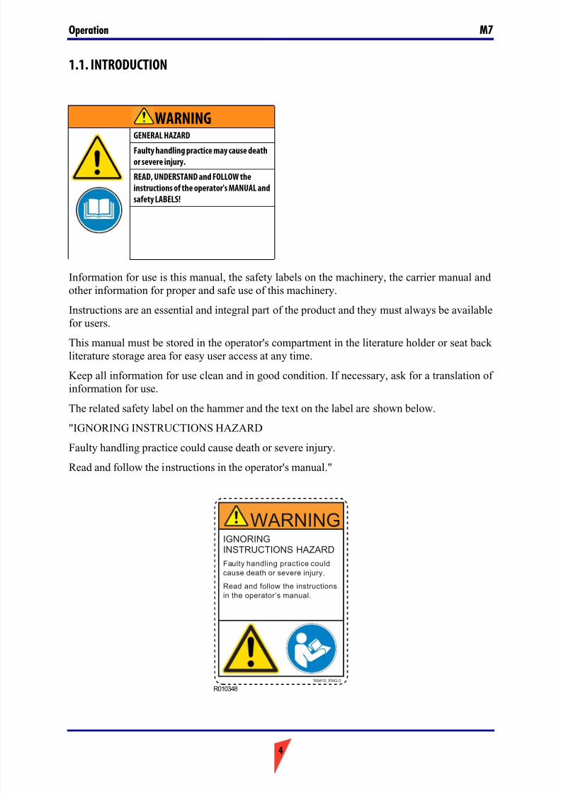
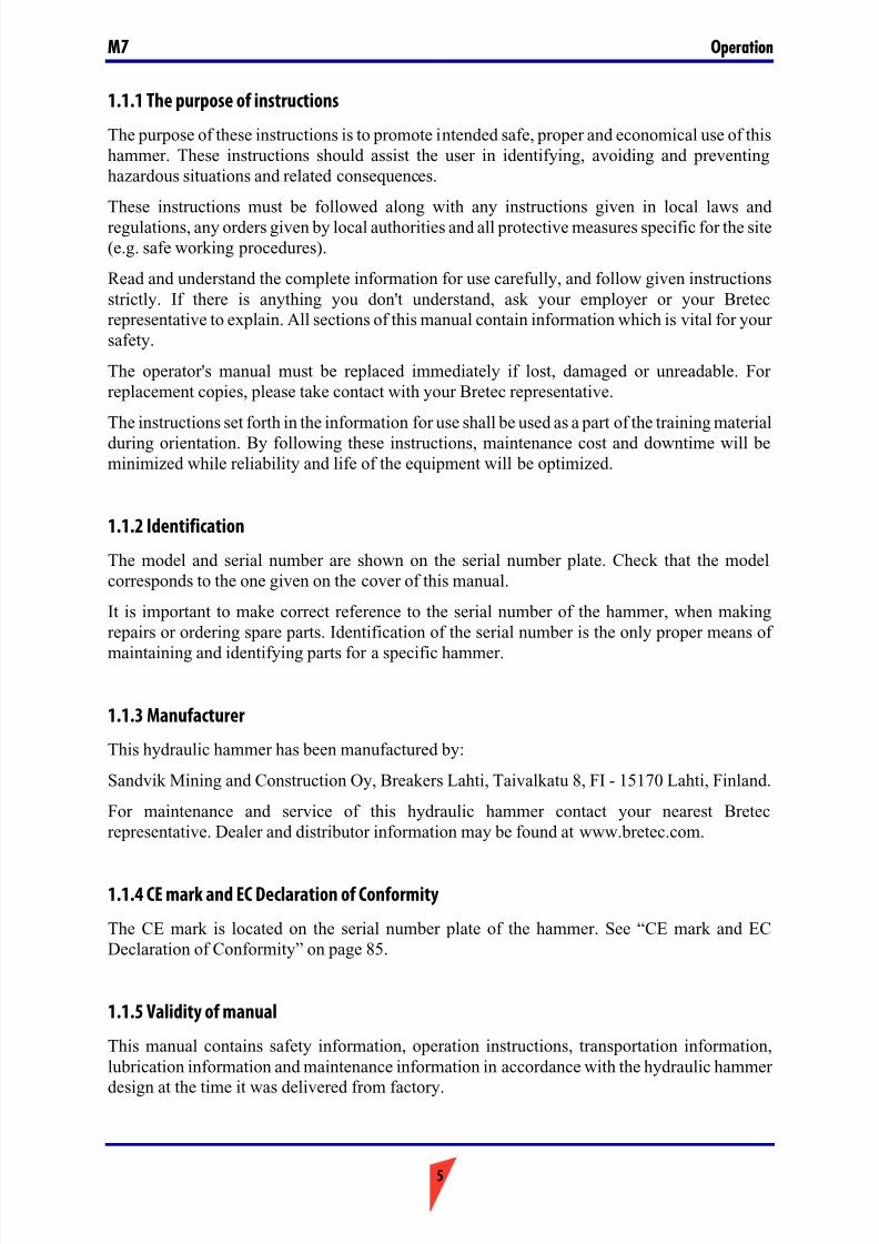
The related safety label on the hammer and the text on the label are shown below.
"IGNORING INSTRUCTIONS HAZARD
Faulty handling practice could cause death or severe injury.
Read and follow the instructions in the operator's manual."
WARNING
GENERAL HAZARDFaulty handling practice may cause death
or severe injury.
READ, UNDERSTAND and FOLLOW the
instructions of the operator's MANUAL and
safety LABELS!
R010348
IGNORINGINSTRUCTIONS HAZARD
Faulty handling practice could
cause death or severe injury.
Read and follow the instructions
in the operator’s manual.
WARNING
169410_ENG-3
7/26/2019 Operators Manual M7
http://slidepdf.com/reader/full/operators-manual-m7 5/88
5
OperationM7
1.1.1 The purpose of instructions
The purpose of these instructions is to promote intended safe, proper and economical use of thishammer. These instructions should assist the user in identifying, avoiding and preventinghazardous situations and related consequences.
These instructions must be followed along with any instructions given in local laws andregulations, any orders given by local authorities and all protective measures specific for the site(e.g. safe working procedures).
Read and understand the complete information for use carefully, and follow given instructionsstrictly. If there is anything you don't understand, ask your employer or your Bretecrepresentative to explain. All sections of this manual contain information which is vital for your safety.
The operator's manual must be replaced immediately if lost, damaged or unreadable. For replacement copies, please take contact with your Bretec representative.
The instructions set forth in the information for use shall be used as a part of the training materialduring orientation. By following these instructions, maintenance cost and downtime will beminimized while reliability and life of the equipment will be optimized.
1.1.2 Identification
The model and serial number are shown on the serial number plate. Check that the modelcorresponds to the one given on the cover of this manual.
It is important to make correct reference to the serial number of the hammer, when makingrepairs or ordering spare parts. Identification of the serial number is the only proper means of
maintaining and identifying parts for a specific hammer.
1.1.3 Manufacturer
This hydraulic hammer has been manufactured by:
Sandvik Mining and Construction Oy, Breakers Lahti, Taivalkatu 8, FI - 15170 Lahti, Finland.
For maintenance and service of this hydraulic hammer contact your nearest Bretecrepresentative. Dealer and distributor information may be found at www.bretec.com.
1.1.4 CE mark and EC Declaration of Conformity
The CE mark is located on the serial number plate of the hammer. See “CE mark and ECDeclaration of Conformity” on page 85.
1.1.5 Validity of manual
This manual contains safety information, operation instructions, transportation information,lubrication information and maintenance information in accordance with the hydraulic hammer
design at the time it was delivered from factory.
7/26/2019 Operators Manual M7
http://slidepdf.com/reader/full/operators-manual-m7 6/88
Operation M7
6
This manual, and especially its safety information as well as the EC declaration of conformityand statement of compliance, are valid only, if no unauthorized changes to the product are made.
Some illustrations in this publication show details that can be different from your hammer.Guards and covers may have been removed for illustrative purposes.
Continuing improvement and advancement of product design may have caused changes to your
hammer, which are not included in this publication.
Whenever a question arises regarding your hammer, or this manual, please consult your dealer for the latest available information.
1.1.6 Copyright notice
This publication is copyright of Sandvik Mining and Construction Oy, Breakers Lahti, Finland.
© Sandvik Mining and Construction Oy , Breakers Lahti, Finland 2013.
It must not be copied, reproduced, or otherwise made available in full or in part to any third partywithout our prior written consent.
All Rights Reserved.
1.1.7 Definitions
Hammer - the product described in this manual.
Tool - the wear part which is in direct contact with the rock.
Carrier - the base machine, onto which the hammer is mounted, and which supplies theoperating power and controls, with which the hammer is operated.
This Manual - this one complete book, which contains vital information for transportation,handling and storage as well as installation, operation and maintenance of the hammer.
Safety Label - label applied on the hammer advising on protective measures for the most severerisks.
Information for Use - the information in this manual, the safety labels on hammer and other information on e.g. the delivery package. This provides protective measures and advice on
proper methods for transportation, installation, operation and maintenance of the hammer.
Intended Use - use of this hammer in accordance with the instructions provided in informationfor use.
Prohibited Use - any use of this hammer, which is not intended use. Especially the use whichis specifically prohibited in information for use.
Reasonably Foreseeable Misuse - use of the hammer in a way not intended, but which mayresult from readily predictable human behaviour.
User - any person handling the hammer, whether it be transportation, installation, operation,scheduled maintenance, scrapping or other.
Harm - physical injury or damage to health. This is always in relationship to people, not to
equipment or property.

7/26/2019 Operators Manual M7
http://slidepdf.com/reader/full/operators-manual-m7 7/88
7
OperationM7
Hazard - potential source of harm.
Risk - the combination of the probability of occurrence of harm and the severity of that harm.
Protective Measure - the measure intended to achieve risk reduction. The protective measuresare implemented by the designer where possible, and by the user, where design measures arenot sufficient for safe operation.
Protective measures for the user are given in the information for use.
User Obligations - protective measures, which must be taken by the user based on theinformation for use.
Hazard Zone - any space around the hammer or the carrier, in which a person can be exposedto a hazard.
Bystander - any person in hazard zone, who is not handling the hammer.
Real Time Hazard Analysis (RTHA) - review of site before starting to work, in order toidentify potential hazards that could impact users, bystanders or environment.
7/26/2019 Operators Manual M7
http://slidepdf.com/reader/full/operators-manual-m7 8/88
Operation M7
8
1.2. SAFETY AND ENVIRONMENTAL INSTRUCTIONS
Safety is the result of attitude. Proper attitude includes:
- Realize the hazards related to what you do, whether it be operation or maintenance. Don'tever take hazards lightly.
- Follow all local laws and regulations. Leave special work to the specialist.
Special conditions, such as e.g. radioactive, asbestos, chemical, poisonous or biologicalhazard environment require unconditional use of hazard specific methods and protectivemeasures.
- Read, understand and follow the instructions of this manual! Read, understand and followthe instructions of carrier manual! If this language version is not proper, ask for a translationof this manual.
- Communicate! Tell other people what you are about to do, so that they do not place you or themselves at risk. Installation or other maintenance related work must never be done alone.
Always keep people informed of what you are doing when and where. Keep mobile phonealways at hand. Advise site manager, when you leave site.
Agree with your colleagues on site on the use of hand signals. Do not assume anyknowledge of signals.
- Wear approved PPE (approved safety boots, approved safety gloves, approved safetyglasses, approved ear protection, approved hard hat). If your PPE is not functioning
properly, get new PPE equipment. Only operate equipment when in fit condition. Bewareof sharp edges of parts.
- Common sense is the most important part of safety in standard hammer applications.
1.2.1 Safety labels
This section includes explanations of safety symbols and labels used on the hammer and ininformation for use.
1.2.1.1 Signal words
The following signal words and symbols are used to identify safety messages in these
instructions:The signal word "DANGER" in white font on red background together with a safety alertsymbol indicates a hazardous situation which, if not avoided, will result in death or seriousinjury.
D010097
7/26/2019 Operators Manual M7
http://slidepdf.com/reader/full/operators-manual-m7 9/88
9
OperationM7
The signal word "WARNING" in black font on orange background together with a safety alertsymbol indicates a hazardous situation which, if not avoided, could result in death or seriousinjury.
The signal word "NOTICE" indicates a situation which, if not avoided, could result in damageto property or environment. A "NOTICE" situation will not involve a specific hazard to people.
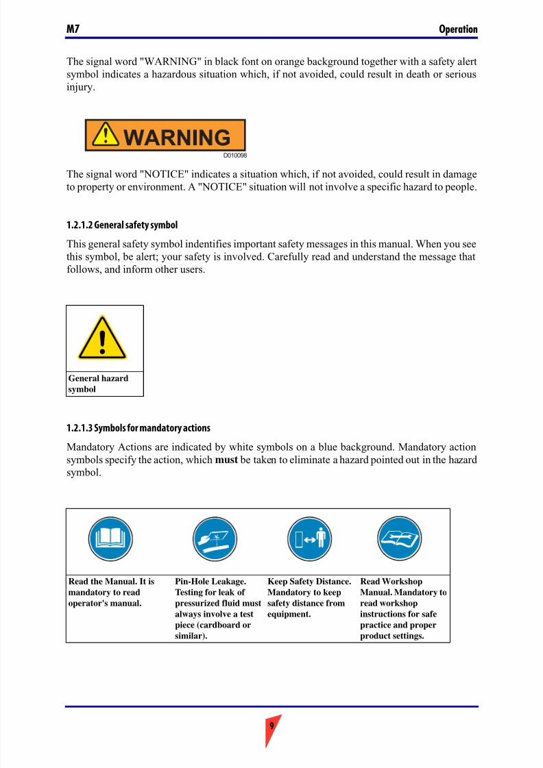
1.2.1.2 General safety symbol
This general safety symbol indentifies important safety messages in this manual. When you seethis symbol, be alert; your safety is involved. Carefully read and understand the message that
follows, and inform other users.
1.2.1.3 Symbols for mandatory actions
Mandatory Actions are indicated by white symbols on a blue background. Mandatory actionsymbols specify the action, which must be taken to eliminate a hazard pointed out in the hazardsymbol.
General hazard
symbol
Read the Manual. It is
mandatory to read
operator's manual.
Pin-Hole Leakage.
Testing for leak of
pressurized fluid must
always involve a test
piece (cardboard or
similar).
Keep Safety Distance.
Mandatory to keep
safety distance from
equipment.
Read Workshop
Manual. Mandatory to
read workshop
instructions for safe
practice and proper
product settings.
D010098
7/26/2019 Operators Manual M7
http://slidepdf.com/reader/full/operators-manual-m7 10/88
Operation M7
10
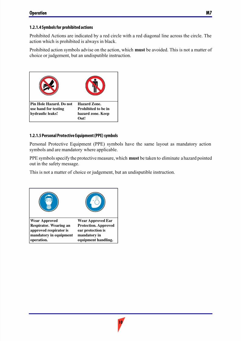
1.2.1.4 Symbols for prohibited actions
Prohibited Actions are indicated by a red circle with a red diagonal line across the circle. Theaction which is prohibited is always in black.
Prohibited action symbols advise on the action, which must be avoided. This is not a matter of choice or judgement, but an undisputible instruction.
1.2.1.5 Personal Protective Equipment (PPE) symbols
Personal Protective Equipment (PPE) symbols have the same layout as mandatory actionsymbols and are mandatory where applicable.
PPE symbols specify the protective measure, which must be taken to eliminate a hazard pointedout in the safety message.
This is not a matter of choice or judgement, but an undisputible instruction.
Pin Hole Hazard. Do not
use hand for testing
hydraulic leaks!
Hazard Zone.
Prohibited to be in
hazard zone. Keep
Out!
Wear Approved
Respirator. Wearing an
approved respirator is
mandatory in equipment
operation.
Wear Approved Ear
Protection. Approved
ear protection is
mandatory in
equipment handling.
7/26/2019 Operators Manual M7
http://slidepdf.com/reader/full/operators-manual-m7 11/88
11
OperationM7
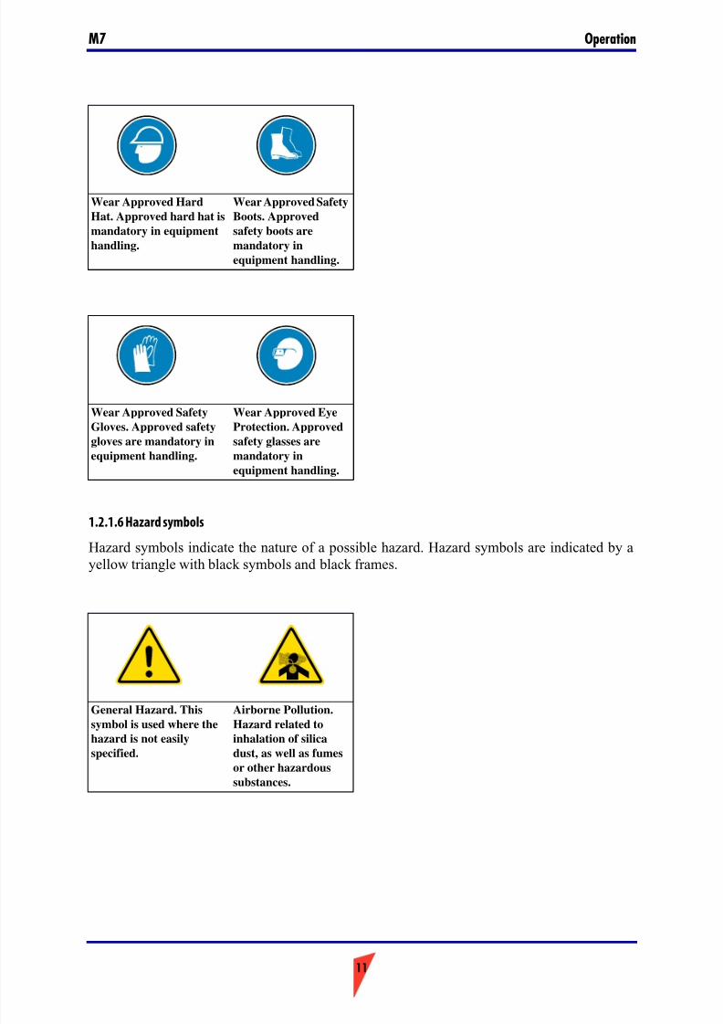
1.2.1.6 Hazard symbols
Hazard symbols indicate the nature of a possible hazard. Hazard symbols are indicated by ayellow triangle with black symbols and black frames.
Wear Approved Hard
Hat. Approved hard hat is
mandatory in equipment
handling.
Wear Approved Safety
Boots. Approved
safety boots are
mandatory in
equipment handling.
Wear Approved Safety
Gloves. Approved safety
gloves are mandatory in
equipment handling.
Wear Approved Eye
Protection. Approved
safety glasses are
mandatory in
equipment handling.
General Hazard. This
symbol is used where the
hazard is not easily
specified.
Airborne Pollution.
Hazard related to
inhalation of silica
dust, as well as fumes
or other hazardous
substances.
7/26/2019 Operators Manual M7
http://slidepdf.com/reader/full/operators-manual-m7 12/88
Operation M7
12
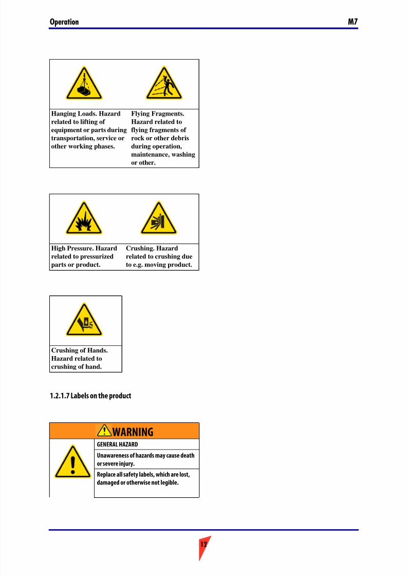
1.2.1.7 Labels on the product
Hanging Loads. Hazard
related to lifting of
equipment or parts during
transportation, service or
other working phases.
Flying Fragments.
Hazard related to
flying fragments of
rock or other debris
during operation,
maintenance, washing
or other.
High Pressure. Hazard
related to pressurized
parts or product.
Crushing. Hazard
related to crushing due
to e.g. moving product.
Crushing of Hands.
Hazard related to
crushing of hand.
WARNINGGENERAL HAZARD
Unawareness of hazards may cause death
or severe injury.
Replace all safety labels, which are lost,
damaged or otherwise not legible.
7/26/2019 Operators Manual M7
http://slidepdf.com/reader/full/operators-manual-m7 13/88
13
OperationM7
Safety labels communicate the following four things:
- The severity level of the risk (i.e. signal word "DANGER" or "WARNING").
- The nature of the hazard (i.e. the type of hazard: high pressure, dust, etc.).
- The consequence of interaction with the hazard.
- How to avoid the hazard.
You must ALWAYS follow the instructions of the safety messages and symbols of the productsafety labels and the instructions set forth in the manuals to avoid death or severe injury!
Keep the safety labels clean and visible at all times. Check the condition of safety labels daily.Safety labels and instructions which have disappeared, been damaged, painted over, come looseor do not meet the legibility requirements for safe viewing distance, must be replaced beforeoperating the product.
If a safety label is attached to a part that is replaced, install a new safety label on the replacement part. If this manual is available in your language, then the safety labels should be available in
the same language.
There are several specific safety labels on this hammer. Please become familiarized with allsafety labels. The location of the safety labels is shown in the illustration below.
When you clean the safety labels, use a cloth, water and soap. Do not use solvent, gasoline or other harsh chemicals to clean the safety labels.
Solvents, gasoline or harsh chemicals could loosen the adhesive that secures the safety labels.Loose adhesive will allow the safety label to fall.

7/26/2019 Operators Manual M7
http://slidepdf.com/reader/full/operators-manual-m7 14/88
Operation M7
14
BA010017
S a n d v i k 16 8 9 0 7
IGNORINGINSTRUCTIONS HAZARD
Faulty handling practice could
cause death or severe injury.
Read and follow the instruct ions
in the operator’s manual.
WARNING
DUST HAZARD
Breathing dust will c ause death
or severe injury.
Always wear appro ved
respirator.
DANGER
FLYING OBJECTS HAZARD
Fragments fly up to 40 m (130 ft)
and could cause death or severe
injury.
Stop operation when a
person enters hazard zone.Wear approved personal
protective equipment.
WARNING
NOISE HAZARD
Continuous exposure to noise
above 80 dB(A) could cause
hearing impairment.
Wear approved hearing
protectors.
WARNING
HIGH PRESSURE HAZARDImproper handling of pressurizedaccumulator will cause death orsevere injury.
Read workshop manual beforedisassembly.
Release pressure before disassembly.
Recharge with nitrogen (N2) only.
DANGER
Hydraulic Hammer
Model:
Serial Number:
Hammer weight:
Min. working weight:
Operating pressure:
Oil flow:
Manufactured:
Versio n:
kg
kg
bar
l/min
Manufacturer:
Address:
SandvikMining andConstruction Oy
Taivalkatu 8, 15170 Lahti,Finland
7/26/2019 Operators Manual M7
http://slidepdf.com/reader/full/operators-manual-m7 15/88
15
OperationM7
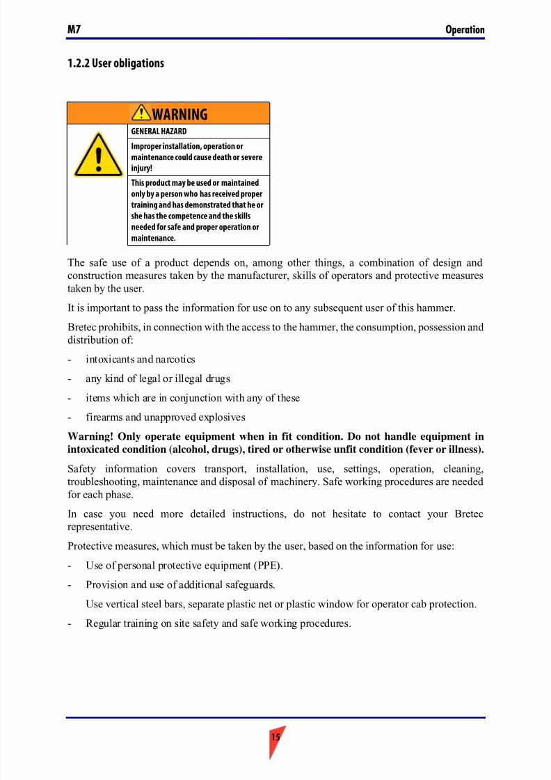
1.2.2 User obligations
The safe use of a product depends on, among other things, a combination of design and
construction measures taken by the manufacturer, skills of operators and protective measurestaken by the user.
It is important to pass the information for use on to any subsequent user of this hammer.
Bretec prohibits, in connection with the access to the hammer, the consumption, possession anddistribution of:
- intoxicants and narcotics
- any kind of legal or illegal drugs
- items which are in conjunction with any of these
- firearms and unapproved explosives
Warning! Only operate equipment when in fit condition. Do not handle equipment in
intoxicated condition (alcohol, drugs), tired or otherwise unfit condition (fever or illness).
Safety information covers transport, installation, use, settings, operation, cleaning,troubleshooting, maintenance and disposal of machinery. Safe working procedures are neededfor each phase.
In case you need more detailed instructions, do not hesitate to contact your Bretecrepresentative.
Protective measures, which must be taken by the user, based on the information for use:- Use of personal protective equipment (PPE).
- Provision and use of additional safeguards.
Use vertical steel bars, separate plastic net or plastic window for operator cab protection.
- Regular training on site safety and safe working procedures.
WARNINGGENERAL HAZARD
Improper installation, operation or
maintenance could cause death or severe
injury!
This product may be used or maintained
only by a person who has received proper
training and has demonstrated that he or
she has the competence and the skills
needed for safe and proper operation or
maintenance.
7/26/2019 Operators Manual M7
http://slidepdf.com/reader/full/operators-manual-m7 16/88
Operation M7
16
Other particular issues which should be known to the user are:
- Site organization and supervision.
- Workplace safety, including safe working procedures.
- Permit-to-work systems.
All near-miss incidents and accidents must be reported to Bretec without delay, where a Bretechammer has been involved.
The following safety guidelines apply for each person working with the hammer or in thevicinity of the hammer:
- Every single person is responsible for the own safety and for the safety of her or hiscolleagues.
- In case of violation of any safety guidelines or regulations, every single person isresponsible to warn the others and the responsible supervisor.
1.2.2.1 Managing work-related hazards
All mechanical equipment can be hazardous if handled without due care or correct maintenance.Most accidents involving equipment handling are caused by failure to observe basic safety rulesor precautions.
Because it is impossible to anticipate every possible circumstance that might involve a potentialhazard, the warnings in this manual and on the equipment are not all inclusive.
Safety is not just a matter of responding to the warnings. All the time you are working with your attachment you must pay attention to the hazards there might be and how to avoid them.
The user must always perform a local risk assessment before starting a task. This assessment,also known as a Real Time Hazard Analysis, ensures that the user stops and thinks about what
she or he is going to do before starting to work:- Perform Real Time Hazard Analysis on site at least daily before starting up. Determine
escape route for emergency situation.
- Identify potential hazards that could impact you, your colleague, the environment, your product and/or work method while you are performing the task.
- Assess the risks and implement the actions needed to eliminate or reduce the risk.
- Make sure that the equipment will not be made unsafe or damaged by the method of operation or maintenance you choose.
WARNING! Authorized spare parts are listed on a spare parts list. Use of non-authorized spare parts may
cause an uncontrolled risk to user health and is thus prohibited.
7/26/2019 Operators Manual M7
http://slidepdf.com/reader/full/operators-manual-m7 17/88
17
OperationM7
Review site before using the hammer. Heavy load of equipment or vibration of hammer work may cause structures (walls, roofing, bridges, floors) to collapse. Keep yourself and bystandersout of hazard zone.
Only competent persons may carry out operation and other tasks. The employer must:
- Provide training and orientation.
- Validate training methods.
- Verify competence and skills.- Monitor and evaluate user performance regularly.
WARNING! This hammer is for professional use only. Especially in equipment rentalapplications the renting company must make sure, that the user has demonstrated the necessaryskills and knowledge for safe and proper operation and maintenance of both carrier andhammer.
Workshop service
1.2.2.2 National safety regulationsIt is the responsibility of the user to follow national safety regulations at all time. Special careshould be given to dust, noise and vibration related regulation.
Ignorance is no excuse for not following national law. Familiarize yourself with the nationalsafety legislation.
1.2.2.3 Site specific safety regulations
Site specific regulations must not contradict national safety regulations. Site specific regulationsshould address issues like transportation of product or equipment, access to site, personal
protective equipment (PPE), working hours, etc.
Site specific regulations should also cover the case of an incident occuring: what to do, who tocontact and other questions.
Site specific regulations must be followed at all time in the same way as national safetyregulations.
WARNING! This hammer may be operated or maintained only by a person who has received proper training
and has demonstrated that he or she has the skills needed for safe and proper operation or maintenance.
7/26/2019 Operators Manual M7
http://slidepdf.com/reader/full/operators-manual-m7 18/88
Operation M7
18
1.2.2.4 Periodic safety inspections
It is important to thoroughly inspect the product before use. The product is inspected to makesure it is safe to operate. Look for defects and damage before any operation so that problemscan be reported and fixed.
The operator is responsible to:
- Check the hammer in accordance with the requirements of the operator's manual before,during and after use and operation.
- Safety features, such as labels, safeguards and others should be checked frequently andrepaired immediately, if damaged.
Respiratory silica dust is a hazard, which requires special attention. Regularly clean your working environment properly to minimize the dust level in the air.
1.2.2.5 Periodic maintenance
Periodic maintenance is an essential procedure to ensure and maintain safety and performanceof the hammer. Follow given instructions for maintenance and inspection of the hammer.
Regular inspections are especially important where hydraulic hoses are concerned.
NOTICE! Poor quality of hydraulic oil, lack of lubrication or too wide clearance between
tool and tool bushing may destroy internal parts of the hammer.
1.2.2.6 Personal Protective Equipment (PPE)
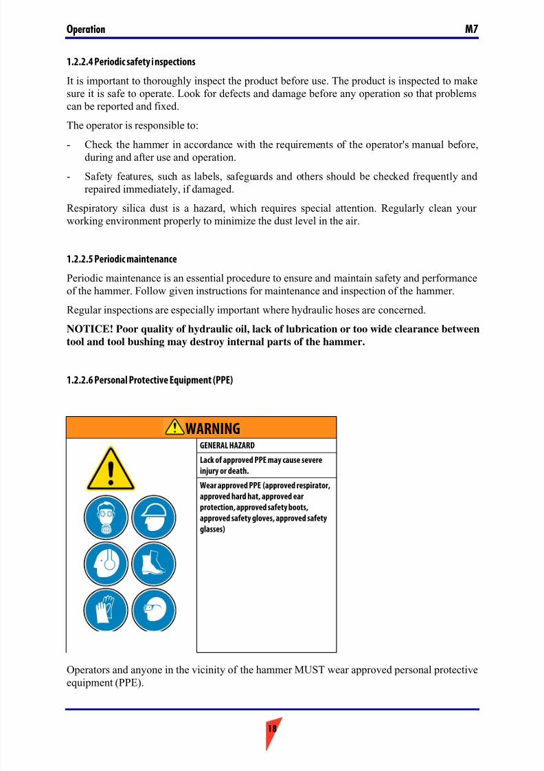
Operators and anyone in the vicinity of the hammer MUST wear approved personal protectiveequipment (PPE).
WARNINGGENERAL HAZARD
Lack of approved PPE may cause severe
injury or death.
Wear approved PPE (approved respirator,
approved hard hat, approved ear
protection, approved safety boots,
approved safety gloves, approved safety
glasses)
7/26/2019 Operators Manual M7
http://slidepdf.com/reader/full/operators-manual-m7 19/88
19
OperationM7
Proper PPE includes (but is not restricted to):
- Approved ear protection
- Approved respirative protection
- Approved eye protection
- Approved safety boots
- Approved hard hat
- Approved protective gloves
- Approved high visibility vest
Do not wear loose clothing or jewelry that can snag on controls or on other parts of theequipment. Confine long hair.
Special conditions may require the use of additional PPE as specified in safe working procedures.
1.2.3 Intended use
Intended use of machinery
This hydraulic hammer is to be used as an attachment on a carrier in demolition, trenching,quarrying or mining applications.
Designed environmental conditions
This hammer is designed to operate in standard environmental conditions with the following
restrictions:- The ambient temperature for use of hammer is -20 °C ... +80 °C.
- WARNING! Use of hammer in explosive atmosphere (gasoline fumes, coal dust, etc.)
is strictly prohibited. The tool in contact with the material to be broken will create sparks,which could ignite an explosive atmosphere.
- NOTICE! Use of hammer under water is strictly prohibited.
Properties of the materials to be processed
This hammer reduces the fragment size of concrete, rock, hard or frozen ground, asphalt,
metallurgical slag or similar material and has been designed exclusively for this application.WARNING! Special conditions with e.g. radioactive, asbestos, chemical, poison or
biological hazards require unconditional use of hazard specific methods and protective
measures.
Under such special conditions, methods and precautions must be reviewed in co-operation withthe local and national authorities. Operation may only commence when approval has beengranted.
Prohibited use of machinery
Any use of this hammer not permitted as intended use, outside the designed environmental
conditions or on unsuitable materials to be processed, is prohibited.
7/26/2019 Operators Manual M7
http://slidepdf.com/reader/full/operators-manual-m7 20/88
Operation M7
20
Use of this hammer is specifically prohibited if:
- Operator has not read and understood this manual.
- Operator has not read and understood operator's manual for the carrier.
- A safety feature of the equipment is defeated for whatever reason.
- Operator has not performed Real Time Hazard Analysis (RTHA) of the site and is not awareof escape route for emergency situation.
- Operator is without proper and approved personal protective equipment.
- People are in hazard zone of hammer.
- Hammer is outside the technical limits as described in the technical specification. Thisapplies especially to carrier weight, hydraulic oil pressure and oil flow.
WARNING! Hammer or lifting eye on hammer must not be used to lift external loads.
WARNING! Hammer must not be used in intoxicated condition (alcohol, drugs), when
tired or when otherwise in unfit condition (fever or illness).
Foreseeable misuse
Foreseeable misuse may be due to carelessness or to pressure to keep product running at anytime.
Reasonably foreseeable misuse is extremely likely to cause considerable damage to people or property. Examples of such behavior are:
- Operating equipment outside limits of use: Do not use equipment on carrier withinsufficient lifting capacity! Do not operate equipment under water! Do not operateequipment outside other limits of use.
- Always perform site and equipment inspection before operation (RTHA).
- Non-professional operation: Do not operate equipment without proper training. Do notoperate, if you are not in fit condition.
- Operating broken equipment: NOTICE! Stop immediately, when you observe failure on
structures or hydraulic leak!
Foreseeable misuse is not an acceptable excuse to cause considerable damage to
equipment, environment or people.
Liability
Bretec will not accept any liability for injury to personnel or damage to equipment caused byunauthorized use, negligence of user obligations or unauthoized modification of this hammer.
1.2.4 Modifications and corrections to the product
All modifications and corrections not authorized in the maintenance manuals or which mayaffect the maintenance, operation, safety, and availability of the product need to be approved inwriting by the manufacturer before implementation. Approval requires a careful risk assessment, taking into consideration the known risks and any new risks that the modifications
may cause.
7/26/2019 Operators Manual M7
http://slidepdf.com/reader/full/operators-manual-m7 21/88
21
OperationM7
Changes and modifications without proper risk assessment, elimination or reduction of risk andwithout appropriate safety measures may lead to death, serious personal injuries or damage to
property.
Unauthorized modifications may add additional weight to the equipment. This may affectstability during lifting and stability of host machine. Unauthorized modifications may disable
safety features and must not be applied.If modifications and corrections that affect the maintenance, operation, safety, and usability of the product are made without the written permission of the manufacturer, the manufacturer isnot responsible for any incidents resulting in death, injury, or property damage brought about
by such modifications and corrections.
Should you consider a modification or correction necessary, please ask your local dealer tocontact the manufacturing and design team of the equipment.
If a modification or correction as described above has been implemented without themanufacturing factory's permission, its effect on warranty liability will be considered case-by-
case. Thus, a warranty application may be rejected altogether.
1.2.5 Hazard zone
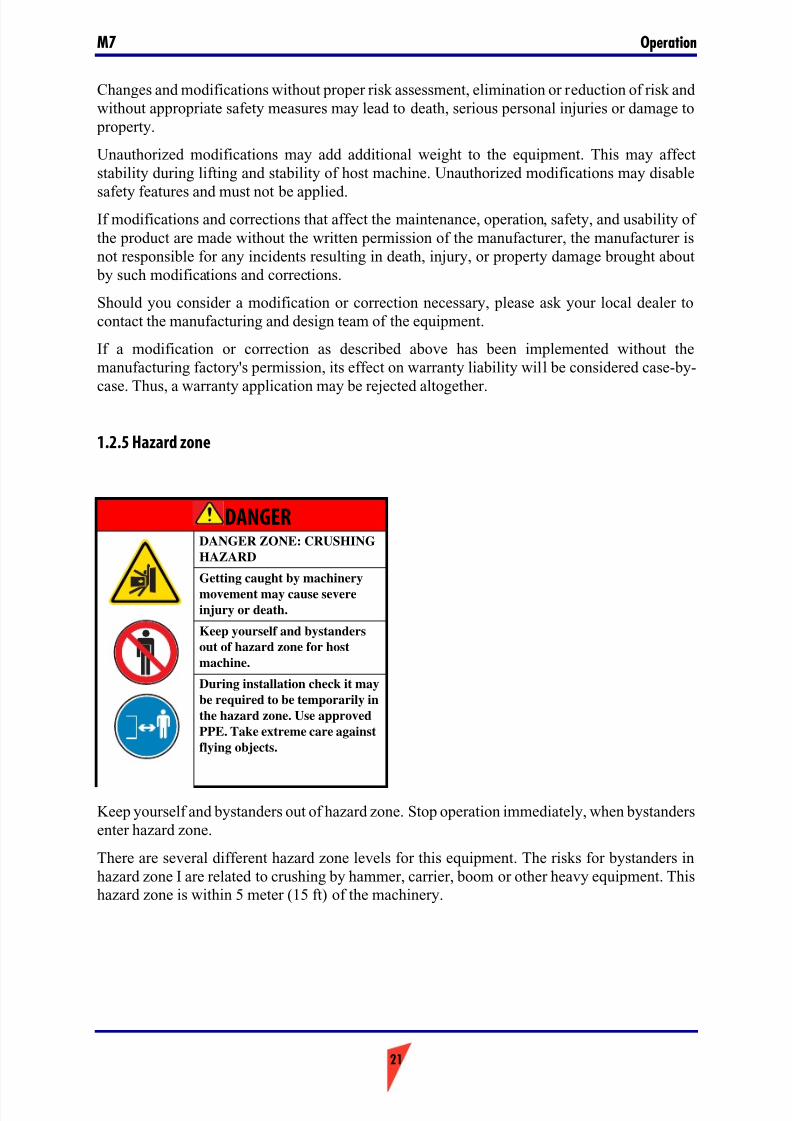
Keep yourself and bystanders out of hazard zone. Stop operation immediately, when bystandersenter hazard zone.
There are several different hazard zone levels for this equipment. The risks for bystanders inhazard zone I are related to crushing by hammer, carrier, boom or other heavy equipment. Thishazard zone is within 5 meter (15 ft) of the machinery.
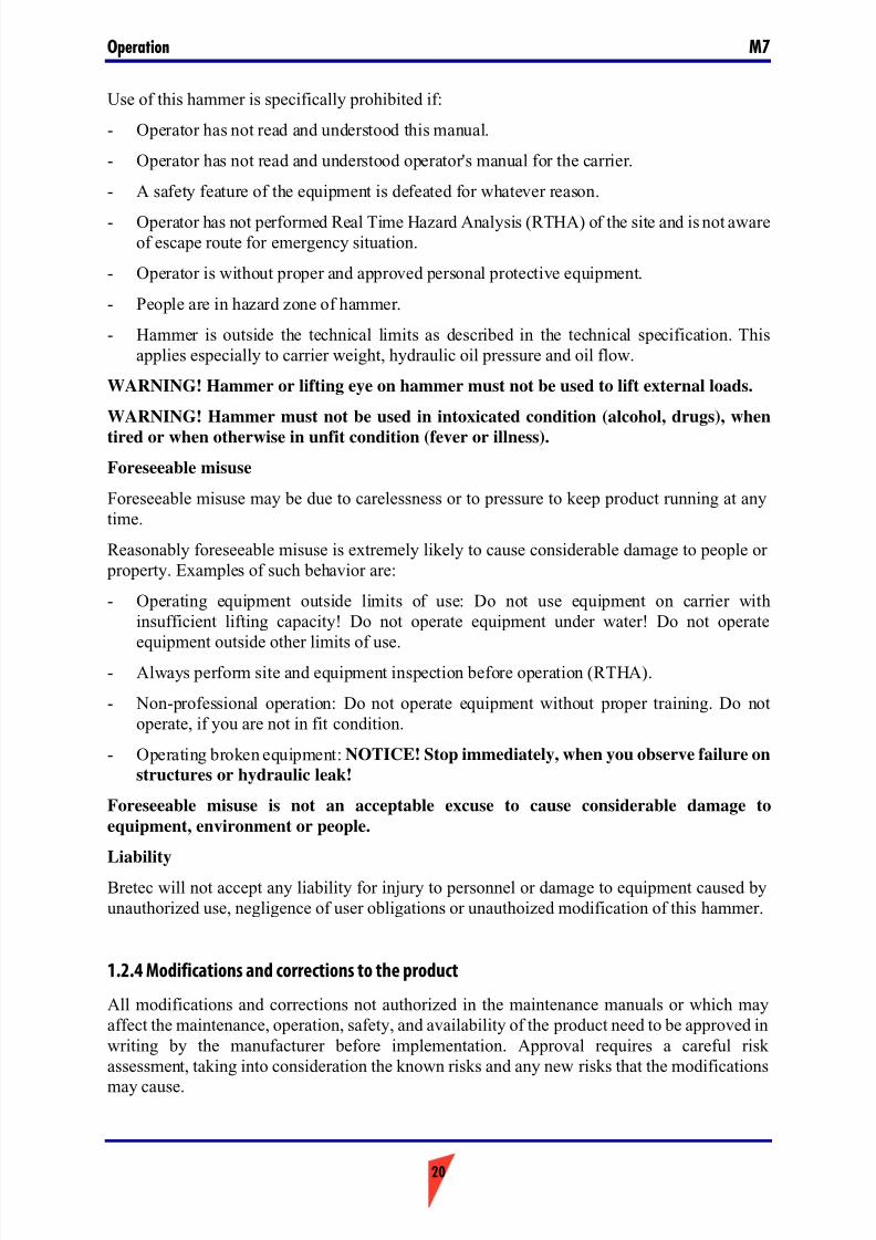
DANGERDANGER ZONE: CRUSHING
HAZARD
Getting caught by machinery
movement may cause severe
injury or death.
Keep yourself and bystanders
out of hazard zone for host
machine.
During installation check it may
be required to be temporarily in
the hazard zone. Use approved
PPE. Take extreme care against
flying objects.
7/26/2019 Operators Manual M7
http://slidepdf.com/reader/full/operators-manual-m7 22/88
Operation M7
22
Nobody is allowed in hazard zone I during hammer operation. WARNING! It is user
obligation to stop hammer operation immediately, when bystanders come into hazard
zone I.
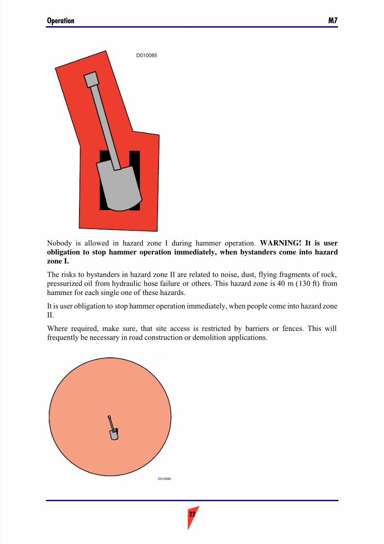
The risks to bystanders in hazard zone II are related to noise, dust, flying fragments of rock,
pressurized oil from hydraulic hose failure or others. This hazard zone is 40 m (130 ft) fromhammer for each single one of these hazards.
It is user obligation to stop hammer operation immediately, when people come into hazard zoneII.
Where required, make sure, that site access is restricted by barriers or fences. This willfrequently be necessary in road construction or demolition applications.
D010085
D010086

7/26/2019 Operators Manual M7
http://slidepdf.com/reader/full/operators-manual-m7 23/88
23
OperationM7
Hazard zone III is related to the stability of the carrier. It is user obligation, to ensure, that thestability of carrier is proper in all working directions, especially when the boom is sideways tothe undercarriage.
7/26/2019 Operators Manual M7
http://slidepdf.com/reader/full/operators-manual-m7 24/88
Operation M7
24
1.3. SAFETY SECTION
This safety section explains the work related risks and gives instructions for proper protectivemeasures against hazards, which may occur on any site.
Read and understand the protective measures listed in this safety section before using the
hammer.
1.3.1 Lifting
Check hammer weight from serial label on hammer. Check weight of mounting bracket and toolas well. Check weight of quick hitch mounting bracket especially with pin mount hammer.
Make sure, that carrier, lifting and transport equipment has proper capacity to carry the weightof equipment.
Faulty lifting procedures or faulty lifting equipment may cause injury or death. Use proper andapproved lifting accessories for lifting of parts heavier than 20 kg. Do not attempt to lift or moveheavy parts manually.
Apply lifting accessories properly and securely. Make sure, that lifting eye is properly fastenedinto fixture. Where required, remove dirt from threaded lifting eye holes and lifting eye thread.Do not use self-made, repaired or damaged lifting accessories.
Make sure, that the lifting eye is proper and approved for complete hammer weight, especially
where mounting bracket is applied. Lifting eyes are not to be side loaded during a liftingoperation. Use shim plates under lifting eye or rotating lifting eyes to avoid unfavorable loaddirection on lifting eye.
Do not use lifting eye on impact unit for lifting of complete hammer.
Do not use the hammer or the hammer's tool for lifting of objects. In most cases the safe liftingcapacity of the excavator is extensively utilized with the weight of hammer, bracket and tool.
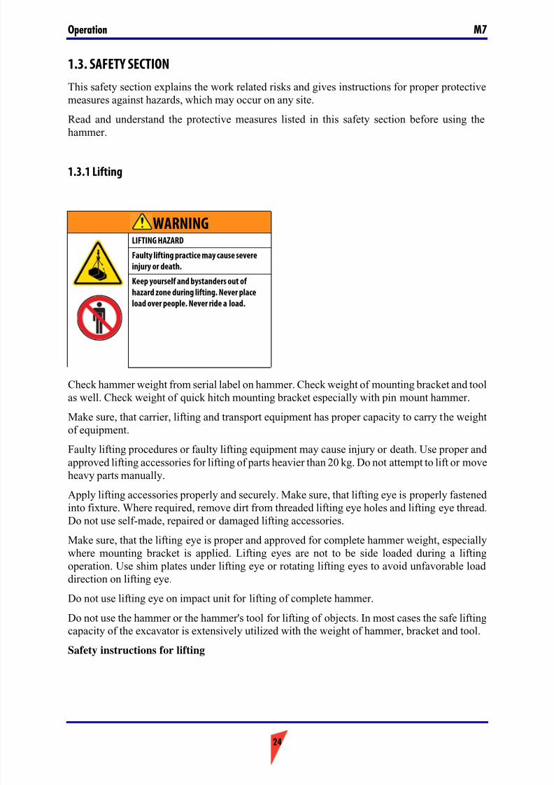
Safety instructions for lifting
WARNINGLIFTING HAZARD
Faulty lifting practice may cause severe
injury or death.
Keep yourself and bystanders out of
hazard zone during lifting. Never place
load over people. Never ride a load.
7/26/2019 Operators Manual M7
http://slidepdf.com/reader/full/operators-manual-m7 25/88
25
OperationM7
Below are some common safety instructions concerning lifting operations. In addition to this,the national standards for machines and lifting-tackles must always be strictly observed. Pleasenote that the list below is not all inclusive. You must always ensure, that the procedure youchoose is safe for yourself and bystanders.
- Do not lift load over people. No one shall be under the hoisted load.
- Do not lift people and never ride the hoisted load.
- Avoid side pull of the load. Make sure you take up the slack slowly. Start and stop carefully.
- Lift load a few centimeters and verify it before proceeding. Make sure the load is well balanced. Check for any loose items.
- Never leave the suspended load unattended. Maintain load control at all times.
- Never lift the load over the rated capacity.
- Inspect all lifting equipment before use. Do not use twisted or damaged lifting equipment.Protect lifting equipment from sharp corners.
- Obey all local safety instructions.
1.3.2 Packing, transportation and storage
Stay clear from hot surfaces. Wear approved PPE.
Use proper and approved lifting accessories for lifting of parts heavier than 20 kg. Do notattempt to lift or move heavy parts manually. Do not attempt to turn or move heavy partsmanually. A sudden change of balance may result in unexpected movement of equipment.
Check hammer weight from serial label on hammer. Check weight of mounting bracket and toolas well. Check weight of quick hitch mounting bracket especially with pin mount hammer.
Make sure, that carrier, lifting and transport equipment has proper capacity to carry the weightof equipment.
During transport, secure other parts, such as hoses, tools, tool box, etc. properly, so that thesecannot move uncontrolled.
Secure equipment properly during transportation and storage. Follow proper transportation practice. Short term storage in horizontal position only.
Store equipment horizontally on level ground, which is able to support the load. Store and
transport equipment on pallet with proper load capacity. Do not stack equipment or pallets withequipment on top of each other.
7/26/2019 Operators Manual M7
http://slidepdf.com/reader/full/operators-manual-m7 26/88
Operation M7
26
1.3.3 Pressurized gas in accumulator
Before e.g. air freight, as well as before any workshop service of hammer, the accumulator must be depressurized.
Use only nitrogen (N2) for recharging accumulators. The use of other gas may causeaccumulators to explode. Failure to comply could result in serious injury or death.
The accumulator charging device does not have any pressure relief valve. Shut gas bottle valvewhen the gauge shows correct charging pressure.
Do not disassemble hammer before releasing gas pressure from accumulators and oil pressurefrom hammer. Failure to comply could result in serious injury or death.
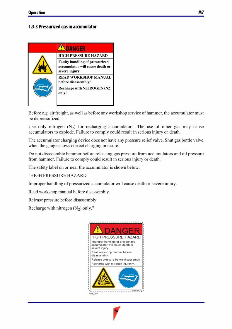
The safety label on or near the accumulator is shown below.
"HIGH PRESSURE HAZARD
Improper handling of pressurized accumulator will cause death or severe injury.
Read workshop manual before disassembly.
Release pressure before disassembly.
Recharge with nitrogen (N2) only."
DANGER
HIGH PRESSURE HAZARDFaulty handling of pressurized
accumulator will cause death or
severe injury.
READ WORKSHOP MANUAL
before disassembly!
Recharge with NITROGEN (N2)
only!
R010357
169400_ENG-9
HIGH PRESSURE HAZARDImproper handling of pressurizedaccumulator will cause death orsevere injury.
Read worksh op manual beforedisassembly.
Release pressure before disassembly.
Recharge with nitrogen (N2) only.
DANGER
7/26/2019 Operators Manual M7
http://slidepdf.com/reader/full/operators-manual-m7 27/88
27
OperationM7
1.3.4 Crushing prevention and cutting prevention
Never mount or dismount the hammer to or from the carrier with the hammer in vertical positionand supported by tool in ground only. The 'breaking' action of the tool will make even relativelyhard ground extremely unstable.
Make sure that the host machine is able to properly support the load of the equipment in alldirections and in all working situations. Stability is an issue especially in long reachapplications.
Support the hammer properly when you perform work beneath the hammer. Do not depend onthe hydraulic cylinders in order to support the hammer. A hammer can fall if a control lever ismoved or if a hydraulic line breaks. Also, a hammer can fall if a hydraulic cylinder drifts.
Whenever there are hammer control linkages, the clearance in the linkage area will change withmovement of the hammer.
Stay clear of all rotating parts and all moving parts. Unless you are instructed otherwise, never attempt adjustments while the machine is moving or while the engine is running.
During storage and transportation make sure, that the load is secured in a proper way. Use proper pallets and make sure the ground is able to support the load.
1.3.5 Removal from package and installation
Clean ice, snow, water, oil or grease spill from floor to prevent slipping, tripping or falling. Useapproved safety boots. Dispose properly (recycle) of spill oil and grease. Make sure, thatlighting conditions are good enough to allow for safe working.
Use proper and approved lifting accessories for lifting of parts heavier than 20 kg. Do notattempt to lift or move heavy parts manually. Do not attempt to turn or move heavy partsmanually. A sudden change of balance may result in unexpected movement of equipment.
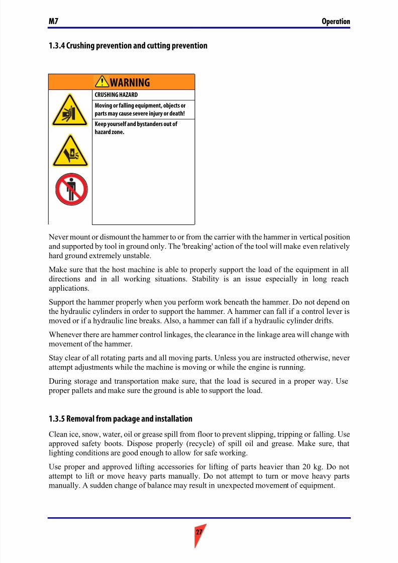
WARNINGCRUSHING HAZARD
Moving or falling equipment, objects or
parts may cause severe injury or death!
Keep yourself and bystanders out of
hazard zone.
7/26/2019 Operators Manual M7
http://slidepdf.com/reader/full/operators-manual-m7 28/88
Operation M7
28
Visually check, that all parts and bolts of the hammer are in place. Check hammer weight fromserial label on hammer. Check weight of mounting bracket and tool as well.
Sudden movement of parts, which were stuck, but become loose may cause crushing of body parts. Beware of sharp edges of parts. Beware of noise from pneumatic or other tools. Wear approved PPE.
Make sure, that carrier, lifting and transport equipment has proper capacity to carry the weightof equipment.
Secure equipment properly during transportation. Follow proper transportation practice. Secureequipment properly during installation. Always keep hammer in horizontal position, whilemounting to carrier!
Agree with your colleagues on site on the use of hand signals. Do not assume any knowledgeof signals.
Place host machine on stable, level ground before starting any installation, service or maintenance on equipment. Do not climb on equipment. Equipment is always hazard zone. Use
proper working platform for safe access. Where working platforms are used, make sure to placethis on level and stable ground.
During installation check it may be required to be temporarily in the hazard zone of the
hammer. Use approved PPE. Take extreme care against flying objects.
Flying fragments are extreme hazard, while driving in tool retaining or other pins. Use
approved eye protection. Use proper tools. Use approved PPE.
Check tool retaining pins on a regular basis. Check tightness of bracket bolts on a regular basis.
Place boom in proper position to allow for ergonomic way of connecting hoses. Check hoseends for proper connection on a regular basis. Use only suitable bolts with proper capacity for mounting of hammer.
Always check hammer function and installation outdoors. Stop engine, when use is notrequired. Make sure, that proper ventilation of exhaust gases is available, when engine isrunning.
Check mounting pin locking mechanism from host machine to pin mount hammer or bracket ona regular basis.
1.3.6 Before use and new users
Secure equipment properly during transportation. Follow proper transportation practice. Makesure, that carrier, lifting and transport equipment has proper capacity to carry the weight of equipment.
Place host machine on stable, level ground before starting any installation, service or maintenance on equipment. Do not climb on equipment. Equipment is always hazard zone. Use
proper working platform for safe access. Where working platforms are used, make sure to placethis on level and stable ground.
Keep yourself and bystanders out of hazard zone for carrier.
7/26/2019 Operators Manual M7
http://slidepdf.com/reader/full/operators-manual-m7 29/88
29
OperationM7
Heavy vibration! Do not touch vibrating hammer or pulsating hoses. Shock hazard makes itextremely difficult to take off hands. Use plastic spiral over hoses to protect against pinholeleak. Use cardboard to check on pinhole leak. Wear proper PPE.
Visually check, that all parts and bolts of the hammer are in place. Check tool retaining pins ona regular basis. Check tightness of bracket bolts on a regular basis.
Flying fragments are extreme hazard, while driving in tool retaining or other pins. Useapproved eye protection. Use proper tools. Use approved PPE.
Place boom in proper position to allow for ergonomic way of connecting hoses. Check hoseends for proper connection on a regular basis. Use only suitable bolts with proper capacity for mounting of hammer.
Always check hammer function and installation outdoors. Stop engine, when use is notrequired. Make sure, that proper ventilation of exhaust gases is available, when engine isrunning.
Check mounting pin locking mechanism from host machine to pin mount hammer or bracket on
a regular basis.
Clear all obstacles that are in the path of the machine. Beware of hazards such as wires, ditches,etc.
Check the stability of the level where you are working. Dropping down a level with excavator will cause severe injury or death.
Know the width of your equipment in order to maintain proper clearance when you operate theequipment near fences or near boundary obstacles.
Be aware of high voltage power lines and power cables that are buried. If the machine comes incontact with these hazards, serious injury or death may occur from electrocution.
Be aware of water and sewage pipelines that are buried.
1.3.7 Operation
Make sure, that lighting conditions are good enough to allow for safe working. Move carefullyon site to avoid tripping, slipping or falling. Use approved safety boots.
Secure equipment properly during transportation. Follow proper transportation practice. Storeand transport equipment on pallet with proper load capacity. Make sure, that carrier, lifting and
transport equipment has proper capacity to carry the weight of equipment. Hammer or liftingeye on hammer must not be used to lift external loads.
Place carrier on stable, level ground before starting any installation, service or maintenance onequipment. Do not climb on equipment. Equipment is always hazard zone. Use proper working
platform for safe access. Where working platform is used, make sure to place this on level andstable ground.
Perform Real Time Hazard Analysis on site at least daily before starting up. Determine escaperoute for emergency situation. Agree with your colleagues on site on the use of hand signals. Donot assume any knowledge of signals.
Always keep people informed of what you are doing when and where. Keep mobile phonealways at hand. Advise site manager, when you leave site.
7/26/2019 Operators Manual M7
http://slidepdf.com/reader/full/operators-manual-m7 30/88
Operation M7
30
Keep yourself and bystanders out of hazard zone for host machine.
With tractor backhoe loader, do not ever drive while boom and hammer are outside wheel widthsideways. Driving with hammer in this 'transport' position may cause severe damage to
pedestrians or passing cars.
Use of hammer in explosive atmosphere (gasoline fumes, coal dust, etc.) is strictly prohibited.
Heavy vibration! Do not touch vibrating hammer or pulsating hoses. Shock hazard makes itextremely difficult to take off hands. Use plastic spiral over hoses to protect against pinholeleak. Use cardboard to check on pinhole leak. Stay clear from hot surfaces. Wear proper PPE.
Extended exposure to whole body vibration may damage your health. Install suitable seating incab. It is strongly recommended to use hammer only on carriers equipped with ROPS/FOPS.
Do not attempt to recharge accumulator. Accumulator is leak proof. Professional service only.Charge accumulator with Nitrogen only!
Visually check, that all parts and bolts of the hammer are in place. Check tool retaining pins on
a regular basis. Check tightness of bracket bolts on a regular basis.Flying fragments are extreme hazard, while driving in tool retaining or other pins. Use
approved eye protection. Use proper tools. Use approved PPE.
Stop engine, when use is not required. Make sure, that proper ventilation of exhaust gases isavailable, when engine is running.
Check mounting pin locking mechanism from host machine to pin mount hammer or bracket ona regular basis.
Respiratory Silica Dust will cause severe injury or death. Always wear approved
respirator.
Use vertical steel bars, separate plastic net or plastic window for operator cab protection. Useair conditioned cab in high temperature applications (metallurgical or similar) as well as at highambient temperature. In high reach or similar bad ergonomy applications, rest tense muscles atregular intervals.
This hammer is for professional use only. Special conditions, such as e.g. radioactive, asbestos,chemical, poisonous or biological hazard environment require unconditional use of hazardspecific methods and protective measures.
1.3.8 Trapped pressure in hydraulic system
Unreleased trapped pressure can cause sudden machine movement or attachment movement.Use caution if you disconnect hydraulic lines or fittings. High pressure oil that is released cancause a hose to whip. High pressure oil that is released can cause oil to spray. Oil may be hotafter prolonged operation.
If you use a lubrication system, make sure to relieve all pressure before any lines, fittings or related items are disconnected.
Before disconnecting or connecting hydraulic hoses, stop carrier engine and operate controls torelease pressure trapped in the hoses.
7/26/2019 Operators Manual M7
http://slidepdf.com/reader/full/operators-manual-m7 31/88
31
OperationM7
Pressure can be trapped in the hydraulic circuit long after the engine has been stopped. The pressure can cause hydraulic fluid or items such as pipe plugs to escape rapidly if the pressureis not relieved correctly.
Wait at least 10 minutes to ensure that pressure has been relieved from the system beforedisconnecting any hoses, pipes or other components. Failure to comply could result in serious
injury or death.
1.3.9 Hot substances
Hot oil and hot components can cause personal injury. Do not allow hot oil to contact the skin.Also, do not allow hot components to contact the skin.
Relieve all pressure in the air system, in the hydraulic system, or in the lubrication system beforeany lines, fittings or related items are disconnected.
Metal parts, such as valves or body parts may have the same temperature as the hydraulic oil.
The working end of the tool may get extremely hot during operation. Make sure the tool has hadtime to cool down before starting to handle it.
1.3.10 Containing fluid spillage
Care must be taken in order to ensure that fluids are contained during performance of inspection,maintenance, testing, adjusting and repair of the equipment. Prepare to collect the fluid withsuitable containers before opening any compartment or disassembling any componentcontaining fluids.
Use tools and equipment, which are suitable for containing and collecting fluids.Improperly disposing of waste can threaten the environment. Always use leakproof containerswhen you drain fluids. Do not pour waste onto the ground, down a drain, or into any source of water.
Obey all local regulations for the disposal of liquids.
1.3.11 Cleaning and service
Replace all safety labels, which are damaged, lost or otherwise not legible.
Clean ice, snow, water, oil or grease spill from floor to prevent slipping, tripping or falling. Useapproved safety boots. Dispose properly (recycle) of spill oil and grease.
Do not climb on equipment. Equipment is always hazard zone. Use proper working platform for safe access.
Heavy vibration! Do not touch vibrating hammer or pulsating hoses. Shock hazard makes itextremely difficult to take off hands. Use plastic spiral over hoses to protect against pinholeleak. Use cardboard to check on pinhole leak. Stay clear from hot surfaces. Wear proper PPE.
Wait for hydraulic oil inside hammer to cool down, before disassembly or service. Oil insidehammer may be extremely hot. Do not handle hydraulic hoses (connect/disconnect) while oil ishot. Use approved PPE.
7/26/2019 Operators Manual M7
http://slidepdf.com/reader/full/operators-manual-m7 32/88
Operation M7
32
Flying fragments are extreme hazard, while driving in tool retaining or other pins. Use
approved eye protection. Use proper tools. Use approved PPE.
Plug pressure and return line before washing the hammer, to prevent water and dirt fromentering into the hammer.
Pressurized air and/or water can cause debris and/or hot water to be blown out. This could result
in personal injury.
When pressurized air and/or pressure water is used for cleaning, wear protective clothing, protective shoes, and eye protection. Eye protection includes safety glasses or a protective faceshield.
The maximum air pressure for cleaning purposes must be below 205 kPa (30 psi). Themaximum water pressure for cleaning purposes must be below 275 kPa (40 psi).
1.3.12 Field repair
Place carrier on stable, level ground before starting any installation, service or maintenance onequipment. Release internal pressure from hammer and accumulator before service,disassembly or scrapping. Charge accumulator with Nitrogen only! Use approved PPE.
Do not attempt to turn or move heavy parts manually. A sudden change of balance may resultin unexpected movement of equipment.
While changing tool, make sure not to leave fingers, hands or other between tool and ground or equipment. Stay clear from hot surfaces. Wear approved PPE.
Secure equipment properly during field service. Always keep hammer in horizontal position!Beware of unexpected boom movement. Do not climb on equipment. Equipment is always
hazard zone. Use proper working platform for safe access.
Flying fragments are extreme hazard, while driving in tool retaining or other pins. Use
approved eye protection. Use proper tools. Use approved PPE.
Attach a "Do Not Operate" warning tag or a similar warning tag to the start switch or to thecontrols before you service the equipment or before you repair the equipment.
Unless you are instructed otherwise, never attempt adjustments while the machine is moving or while the engine is running. Stay clear of all rotating parts and all moving parts.
Before welding on the hammer while it is mounted on the carrier, disconnect the carrier
alternator and battery. Note that welding on hammer tools will render them useless.Use all cleaning solutions with care. Never put maintenance fluids into glass containers. Drainall liquids into a suitable container.
1.3.13 Dismounting
Make sure, that carrier, lifting and transport equipment have proper capacity to carry the weightof equipment.
7/26/2019 Operators Manual M7
http://slidepdf.com/reader/full/operators-manual-m7 33/88
33
OperationM7
Keep yourself and bystanders out of hazard zone during lifting. Never place load over people. Never ride a load. Do not use self-made, repaired or damaged lifting accessories. Apply liftingaccessories properly and securely. Secure equipment properly during transportation. Follow
proper transportation practice.
While changing tool, make sure not to leave fingers, hands or other between tool and ground or
equipment.Oil inside hammer may be extremely hot. Do not handle hydraulic hoses (connect/disconnect)while oil is hot. Stay clear from hot surfaces. Use approved PPE.
Secure equipment properly during field service. Always keep hammer in horizontal position!Beware of unexpected boom movement. Do not climb on equipment. Equipment is alwayshazard zone. Use proper working platform for safe access.
1.3.14 Workshop service
Workshop service must be performed at a trained and Bretec approved workshop. Non- professional service will be a severe risk for the staff performing the service. Non-professionalservice may be a risk for the operator as well, while most certainly causing damage toequipment, which may become extremely expensive.
1.3.15 Scrapping
While removing tool, make sure not to leave fingers, hands or other between tool and ground or equipment.
Release internal pressure from hammer and accumulator before service, disassembly or scrapping. Drain hydraulic hammer of fluids before scrapping. Use approved PPE.
Plastic (wear plates, foam rubber, etc.) and rubber (seals, vibration dampening elements, plugs) parts should be deposited at dump. Do not burn.
Obey all local regulations for the disposal of liquids.
Improperly disposal of waste can threaten the environment. Always use leakproof containerswhen you drain fluids. Do not pour waste onto the ground, down a drain, or into any source of water.
All metal parts of the hammer may be recycled as standard scrap recycling.
All plastic parts (seals, buffers, plugs) of the hammer should be deposited on a standard wastedeposit. Plastic parts must not be burned.
1.3.16 Flammable liquids
All fuels, most lubricants, and some coolant mixtures are flammable.
Flammable fluids that, are leaking or spilled onto hot surfaces or onto electrical components cancause a fire. Fire may cause personal injury and property damage.
Remove all flammable materials such as fuel, oil, and debris from the hammer. Do not allowany flammable materials to accumulate on the hammer.
7/26/2019 Operators Manual M7
http://slidepdf.com/reader/full/operators-manual-m7 34/88
Operation M7
34
Store fuels and lubricants in properly marked containers away from unauthorized persons. Storeoily rags and any flammable materials in protective containers. Do not smoke in areas that areused for storing flammable materials.
Do not operate the hammer near any flame.
Do not weld on lines or on tanks that contain flammable fluids. Do not flame cut lines or tanks
that contain flammable fluid. Clean any such lines or tanks thoroughly with a nonflammablesolvent prior to welding or flame cutting.
7/26/2019 Operators Manual M7
http://slidepdf.com/reader/full/operators-manual-m7 35/88
35
OperationM7
1.4. SAFETY DURING OPERATION
1.4.1 Proper operating practice
Only operate the hammer while you are in the seat of the host machine. The seat belt must be
fastened while you operate the host machine. Only operate the controls while the engine isrunning. Protective glasses must be worn while you operate the host machine and while youoperate the hammer.
While you operate the hammer slowly in an open area, check for proper operation of all controlsand all protective devices. Before you move the host machine with the hammer, ensure that noone will be endangered.
Carry the hammer low to the ground. Do not go close to the edge of a cliff, an excavation, or anoverhang.
Maintain control of the host machine while you operate the hammer. Operating the equipment
beyond its design limits can cause damage to people or equipment.
Know the maximum operating dimensions of your excavator when the hammer is installed.
Ensure that there is adequate clearance between the tool and any stationary objects when youare maneuvering the machine.
Know the appropriate work site hand signals and the personnel that are authorized to give thehand signals. Confirm your understanding of the signs with the other person before starting.Accept hand signals from one person only.
Do not allow unauthorized personnel on the equipment.
During operation, the tip of the tool may get extremely hot. Do not operate the hammer near flammable liquids.
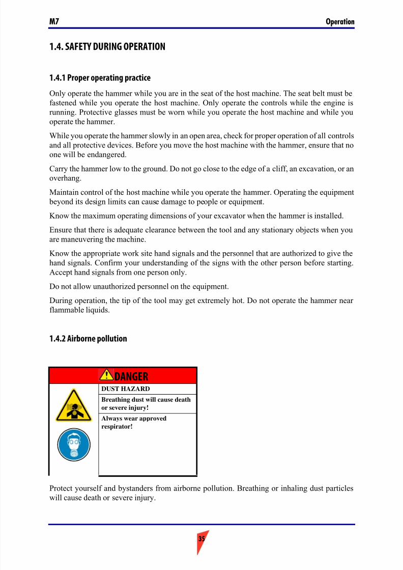
1.4.2 Airborne pollution
Protect yourself and bystanders from airborne pollution. Breathing or inhaling dust particles
will cause death or severe injury.
DANGERDUST HAZARD
Breathing dust will cause deathor severe injury!
Always wear approved
respirator!
7/26/2019 Operators Manual M7
http://slidepdf.com/reader/full/operators-manual-m7 36/88
Operation M7
36
Always work with a respirator approved by the respirator manufacturer for the job you aredoing. It is essential that the respirator that you use protects you from the tiny dust particleswhich cause silicosis and which may cause other serious lung diseases.
You should not use the equipment until you are sure your respirator is working properly. Thismeans the respirator must be checked to make sure that it is clean, that its filter has been
changed, and to otherwise make sure the respirator will protect you in the way it is meant to.Make sure the dust suppression system in your equipment is working properly. If the dustsuppression system is not working properly, stop working immediately.
Always make sure dust has been cleaned off your boots and clothes when you leave your shift.
The smallest particles of dust are the most harmful. They may be so fine that you can not seethem.
Remember, you must protect yourself from the danger of breathing or inhaling dust. Failure tocomply will result in serious injury or death.
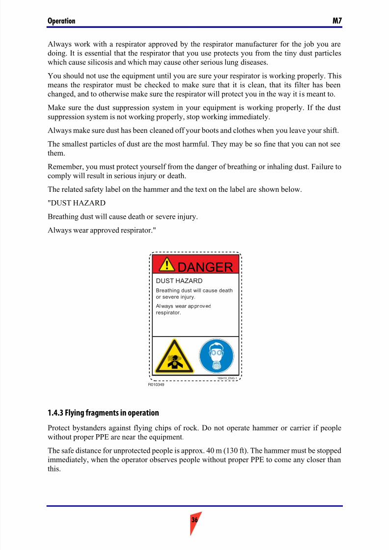
The related safety label on the hammer and the text on the label are shown below."DUST HAZARD
Breathing dust will cause death or severe injury.
Always wear approved respirator."
1.4.3 Flying fragments in operation
Protect bystanders against flying chips of rock. Do not operate hammer or carrier if peoplewithout proper PPE are near the equipment.
The safe distance for unprotected people is approx. 40 m (130 ft). The hammer must be stoppedimmediately, when the operator observes people without proper PPE to come any closer thanthis.
R010349
DUST HAZARD
Breathing dust will cause deathor severe injury.
Always wear approved
respirator.
DANGER
169410_ENG-1
7/26/2019 Operators Manual M7
http://slidepdf.com/reader/full/operators-manual-m7 37/88
37
OperationM7
Where there is need to work at closer distance to unprotected people or structures, safety barriers with the ability to stop flying fragments must be erected.
Safety barriers must also be erected, where unprotected bystanders may be crossing through thehazard zone (= reasonably foreseeable misuse).
Protect yourself against flying chips of rock. Flying objects or debris can cause serious injury
or death. To prevent injury to your eyes or to your ears, wear eye protection or hearing protection when you operate the machine.
The European standard EN 474-1 on safety of earth-moving machinery requires that adequateoperator's protection, such as bullet proof glass, mesh guard or an equivalent protection is usedon excavators equipped with a hammer.
Always make sure the machine is equipped with a flying object guard.
When measuring hammer operating pressure, you are working in the hammer's danger area.Stay clear of moving equipment. Use proper PPE. Failure to comply could result in seriousinjury or death.
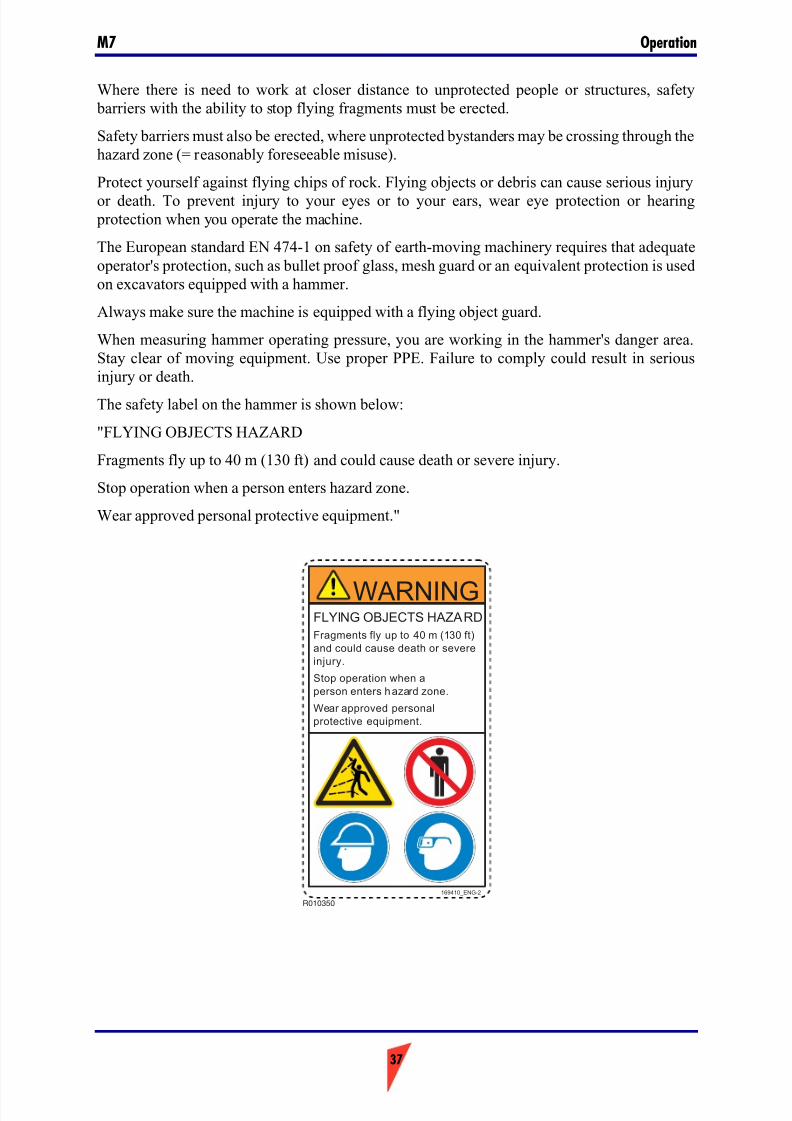
The safety label on the hammer is shown below:
"FLYING OBJECTS HAZARD
Fragments fly up to 40 m (130 ft) and could cause death or severe injury.
Stop operation when a person enters hazard zone.
Wear approved personal protective equipment."
R010350
FLYING OBJECTS HAZARD
Fragments fly up to 40 m (130 ft)
and could cause death or severe
injury.
Stop operation when a
person enters hazard zone.
Wear approved personal
protective equipment.
WARNING
169410_ENG-2
7/26/2019 Operators Manual M7
http://slidepdf.com/reader/full/operators-manual-m7 38/88
Operation M7
38
1.4.4 Noise
A hammer in operation creates a high noise level. Always wear ear protection to prevent personal injury.
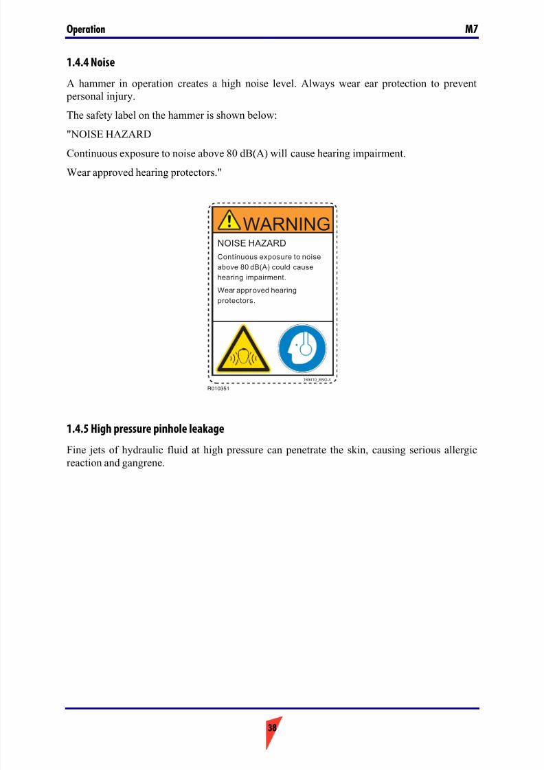
The safety label on the hammer is shown below:
"NOISE HAZARDContinuous exposure to noise above 80 dB(A) will cause hearing impairment.
Wear approved hearing protectors."
1.4.5 High pressure pinhole leakage
Fine jets of hydraulic fluid at high pressure can penetrate the skin, causing serious allergicreaction and gangrene.
R010351
NOISE HAZARD
Continuous exposure to noise
above 80 dB(A) could causehearing impairment.
Wear approved hearing
protectors.
WARNING
169410_ENG-4
7/26/2019 Operators Manual M7
http://slidepdf.com/reader/full/operators-manual-m7 39/88
39
OperationM7
Always hold a piece of cardboard close to suspected leaks and then inspect the cardboard for signs of hydraulic fluid leak. If fluid is injected into your skin, you must get treatmentimmediately. Seek treatment from a doctor, who is familiar with this type of injury.
During hammer operation, keep people away from the hydraulic hoses.
Hydraulic fluid at system pressure may cause injury. Before disconnecting or connectinghydraulic hoses, stop the carrier engine and operate the controls to release pressure trapped inthe hoses.
Make sure to let the hydraulic fluid cool down to ambient temperature, before disconnecting thehoses.
Always use leakproof containers when you drain fluids. Do not pour waste onto the ground,down a drain, or into any source of water.
Improper disposal of waste can threaten the environment. Potentially harmful fluids should bedisposed of according to local regulations.
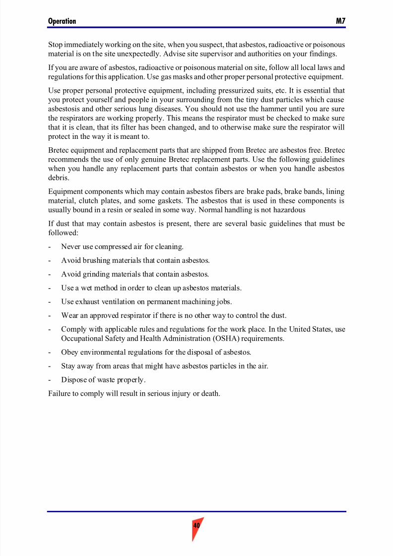
1.4.6 Asbestos, radioactive or poisonous applications
Protect yourself and bystanders from asbestos, radioactive or poisonous airborne pollution.
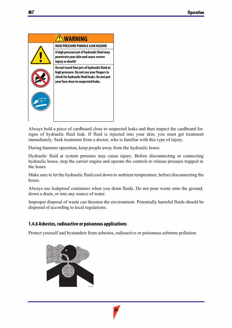
WARNINGHIGH PRESSURE PINHOLE LEAK HAZARD
A high pressure jet of hydraulic fluid may
penetrate your skin and cause severeinjury or death!
Do not touch fine jets of hydraulic fluid at
high pressure. Do not use your fingers to
check for hydraulic fluid leaks. Do not put
your face close to suspected leaks.
D010100
7/26/2019 Operators Manual M7
http://slidepdf.com/reader/full/operators-manual-m7 40/88
Operation M7
40
Stop immediately working on the site, when you suspect, that asbestos, radioactive or poisonousmaterial is on the site unexpectedly. Advise site supervisor and authorities on your findings.
If you are aware of asbestos, radioactive or poisonous material on site, follow all local laws andregulations for this application. Use gas masks and other proper personal protective equipment.
Use proper personal protective equipment, including pressurized suits, etc. It is essential that
you protect yourself and people in your surrounding from the tiny dust particles which causeasbestosis and other serious lung diseases. You should not use the hammer until you are surethe respirators are working properly. This means the respirator must be checked to make surethat it is clean, that its filter has been changed, and to otherwise make sure the respirator will
protect in the way it is meant to.
Bretec equipment and replacement parts that are shipped from Bretec are asbestos free. Bretecrecommends the use of only genuine Bretec replacement parts. Use the following guidelineswhen you handle any replacement parts that contain asbestos or when you handle asbestosdebris.
Equipment components which may contain asbestos fibers are brake pads, brake bands, liningmaterial, clutch plates, and some gaskets. The asbestos that is used in these components isusually bound in a resin or sealed in some way. Normal handling is not hazardous
If dust that may contain asbestos is present, there are several basic guidelines that must befollowed:
- Never use compressed air for cleaning.
- Avoid brushing materials that contain asbestos.
- Avoid grinding materials that contain asbestos.
- Use a wet method in order to clean up asbestos materials.
- Use exhaust ventilation on permanent machining jobs.
- Wear an approved respirator if there is no other way to control the dust.
- Comply with applicable rules and regulations for the work place. In the United States, useOccupational Safety and Health Administration (OSHA) requirements.
- Obey environmental regulations for the disposal of asbestos.
- Stay away from areas that might have asbestos particles in the air.
- Dispose of waste properly.
Failure to comply will result in serious injury or death.
7/26/2019 Operators Manual M7
http://slidepdf.com/reader/full/operators-manual-m7 41/88
41
OperationM7
1.5. TRANSPORTATION, STORAGE AND SETTING UP
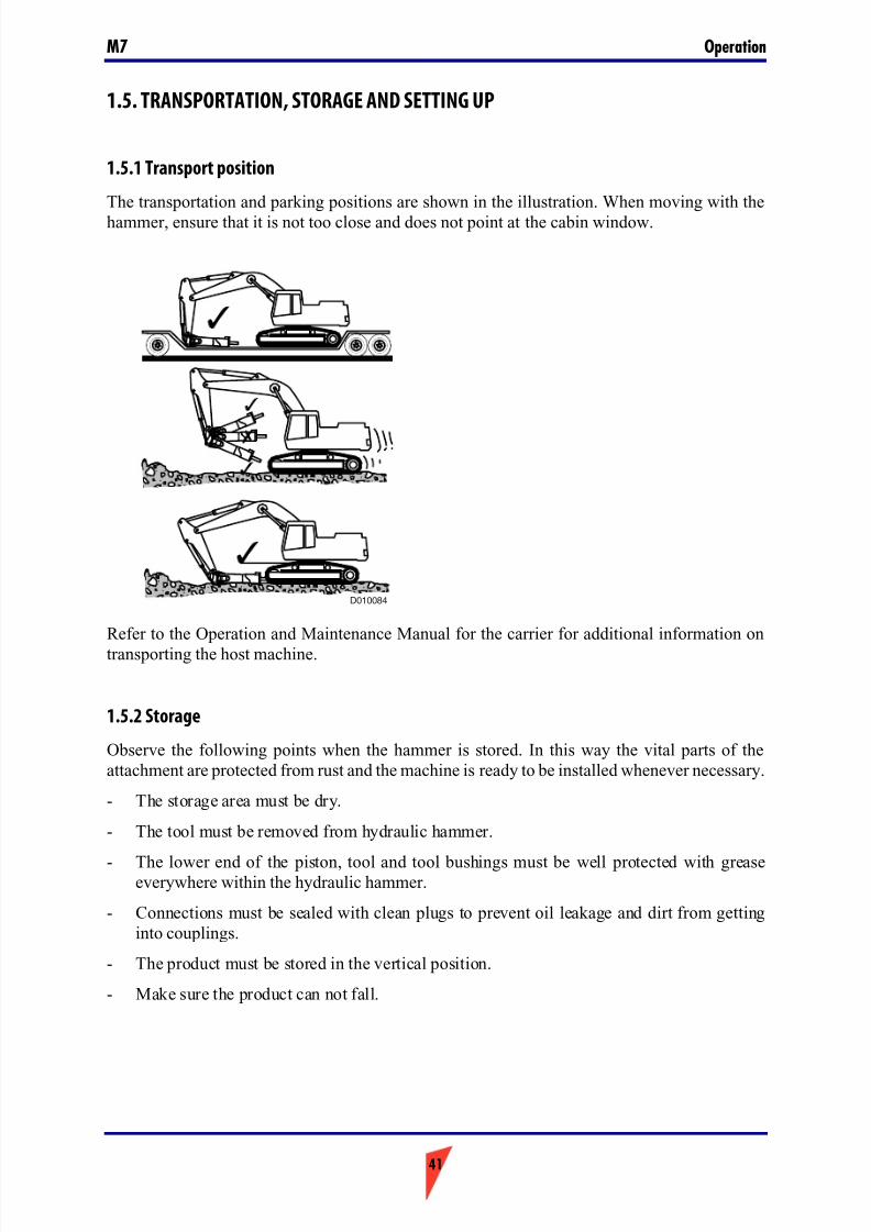
1.5.1 Transport position
The transportation and parking positions are shown in the illustration. When moving with the
hammer, ensure that it is not too close and does not point at the cabin window.
Refer to the Operation and Maintenance Manual for the carrier for additional information on
transporting the host machine.
1.5.2 Storage
Observe the following points when the hammer is stored. In this way the vital parts of theattachment are protected from rust and the machine is ready to be installed whenever necessary.
- The storage area must be dry.
- The tool must be removed from hydraulic hammer.
- The lower end of the piston, tool and tool bushings must be well protected with greaseeverywhere within the hydraulic hammer.
- Connections must be sealed with clean plugs to prevent oil leakage and dirt from gettinginto couplings.
- The product must be stored in the vertical position.
- Make sure the product can not fall.
D010084

7/26/2019 Operators Manual M7
http://slidepdf.com/reader/full/operators-manual-m7 42/88
Operation M7
42
1.5.3 Setting up
Verify that the hammer is compatible with the carrier. Consult your Bretec dealer for moreinformation.
Verify, that all parts, which you have specified are delivered.
Verify that the mounting bracket (standard or quick hitch) is the correct mounting bracket for the carrier and the hammer.
If the carrier is equipped with a quick hitch mounting bracket, consult the operating manual for the quick hitch bracket before you attempt to mount the hammer.
- A heavy structure of the bracket may increase the weight of the attachment more than thelifting capacity of the host machine allows.
- A light structure of the bracket may not be able to support the hammer properly.
- Faulty bracket geometry may lead to contact and expensive damage the boom cylinders.
Mount or dismount the hammer to or from the boom only while the hammer is in horizontal position. If the hammer is in a standing position, it may fall over due to insufficient support fromground or due to sudden movement of the boom.
Tighten the bracket bolts to the proper torque value.
When measuring hammer operating pressure, you are in the hammer's danger area. Stay clear of moving equipment. Use proper PPE. Failure to comply could result in serious injury or death.
7/26/2019 Operators Manual M7
http://slidepdf.com/reader/full/operators-manual-m7 43/88
43
OperationM7
1.6. HAMMER INSTALLATION AND REMOVAL
1.6.1 Preparing for installation
Before you install the hammer, you must have verification of the setup of the hydraulic system
for the carrier, or you must perform the following steps:
- You must verify the setting of the relief valve for the auxiliary system. If the pressure is notcorrect, you must adjust the relief valve to the proper pressure setting.
- You must verify the back pressure of the return flow of the hydraulic system. Refer to the"Specifications" section for the proper specifications for your machine. For moreinformation, consult your Bretec dealer.
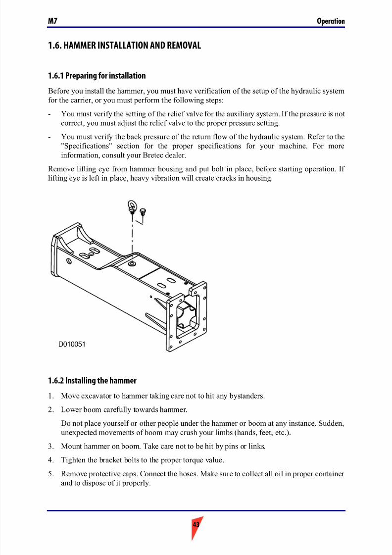
Remove lifting eye from hammer housing and put bolt in place, before starting operation. If lifting eye is left in place, heavy vibration will create cracks in housing.
1.6.2 Installing the hammer
1. Move excavator to hammer taking care not to hit any bystanders.
2. Lower boom carefully towards hammer.
Do not place yourself or other people under the hammer or boom at any instance. Sudden,unexpected movements of boom may crush your limbs (hands, feet, etc.).
3. Mount hammer on boom. Take care not to be hit by pins or links.
4. Tighten the bracket bolts to the proper torque value.
5. Remove protective caps. Connect the hoses. Make sure to collect all oil in proper container
and to dispose of it properly.
D010051

7/26/2019 Operators Manual M7
http://slidepdf.com/reader/full/operators-manual-m7 44/88
Operation M7
44
6. Open the pressure line and tank line valves on boom.
7. Check that oil flow, operating pressure and return line pressure are within specification.
1.6.3 Removing the hammer
1. Move excavator and hammer to solid, clean ground.
2. Lower boom and hammer to ground, placing the hammer on solid and level wooden blocks.
Do not place yourself or other people under the hammer or boom at any instance. Sudden,unexpected movements of boom may crush your limbs (hands, feet, etc.).
3. Stop engine. Turn off the main switch. Move the controls, to release trapped pressure.
4. Close the pressure line and tank line valves on boom, to prevent oil from leaking to theground.
5. Disconnect the hoses. Make sure to collect all oil in proper container and to dispose of it properly.
Plug hoses and pipeline ends immediately, in order to prevent dust entering the system.
6. Remove mounting bracket or mounting pins. Take care not to be hit by released pins or links.
7. When hammer is stored for more than a week, clean it and cover it with protective plastic.
IN OUT
BA010013
D010045

7/26/2019 Operators Manual M7
http://slidepdf.com/reader/full/operators-manual-m7 45/88
45
OperationM7
1.7. OPERATION
1.7.1 Underwater use
The hammer must not be used under water.
If seals get damaged in underwater use, oil may escape into the environment, such as rivers,lakes or groundwater reservoirs. Only minor amounts of hydraulic oil are required to completelydamage drinking water for a very long time!
The hammer may be damaged by strong pressure waves, if the space between piston and tool isfilled with water.
If seals get damaged in underwater use, water will enter the hydraulic circuit of the excavator.This will result in expensive damage to equipment.
1.7.2 Idle strokesConstant idle strokes have a deteriorating effect on the hammer and side plates. These will thenwear out quicker.
Vibration caused by constant idle strokes will damage the excavator structures and causeadditional fatigue to the operator.
1.7.3 Penetrative breaking
In penetrative breaking, a moil tool or a chisel tool is forced inside the material. Penetrative
breaking is more effective in the following materials: soft material, layered material, plasticmaterial, and low abrasive material. Hammers with a higher rate of impact (BPM) are ideal for
penetrative breaking.
1.7.4 Operating techniques
Only use the hydraulic hammer to break rocks, concrete, and other hard objects. Before you starthydraulic hammer operation, place the carrier on a level, stable surface. If the carrier must be
placed on a slope or on a rough surface, be careful during operation.
Never operate the hydraulic hammer when you cannot see the hydraulic hammer. Always position the carrier so you can always see the hydraulic hammer and the area of work.
D010081
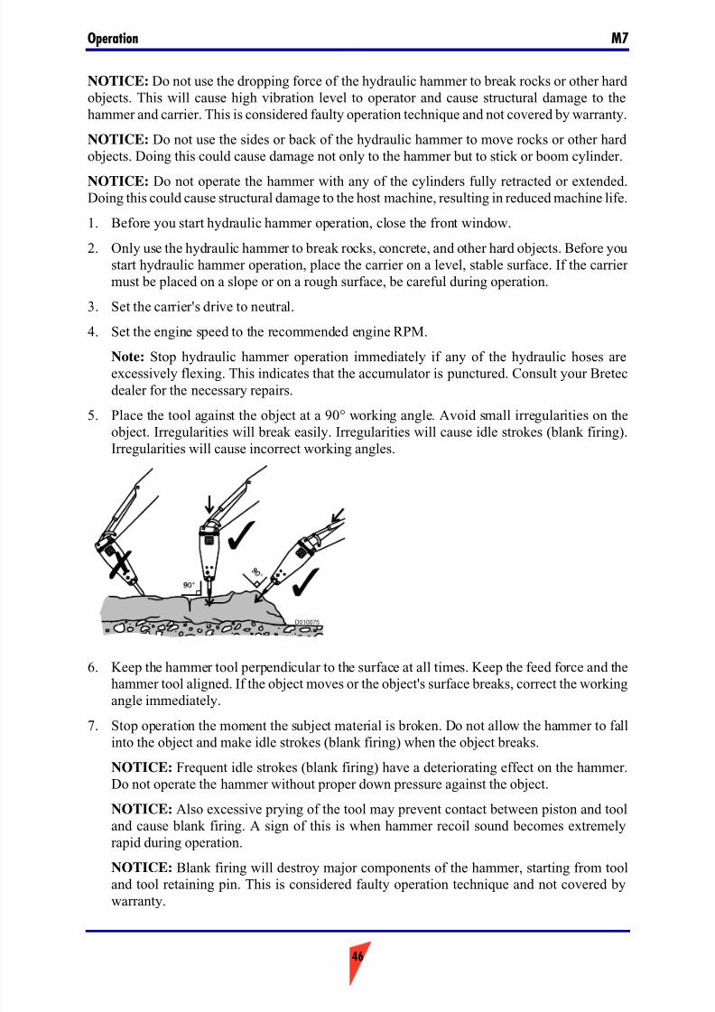
7/26/2019 Operators Manual M7
http://slidepdf.com/reader/full/operators-manual-m7 46/88
Operation M7
46
NOTICE: Do not use the dropping force of the hydraulic hammer to break rocks or other hardobjects. This will cause high vibration level to operator and cause structural damage to thehammer and carrier. This is considered faulty operation technique and not covered by warranty.
NOTICE: Do not use the sides or back of the hydraulic hammer to move rocks or other hardobjects. Doing this could cause damage not only to the hammer but to stick or boom cylinder.
NOTICE: Do not operate the hammer with any of the cylinders fully retracted or extended.Doing this could cause structural damage to the host machine, resulting in reduced machine life.
1. Before you start hydraulic hammer operation, close the front window.
2. Only use the hydraulic hammer to break rocks, concrete, and other hard objects. Before youstart hydraulic hammer operation, place the carrier on a level, stable surface. If the carrier must be placed on a slope or on a rough surface, be careful during operation.
3. Set the carrier's drive to neutral.
4. Set the engine speed to the recommended engine RPM.
Note: Stop hydraulic hammer operation immediately if any of the hydraulic hoses areexcessively flexing. This indicates that the accumulator is punctured. Consult your Bretecdealer for the necessary repairs.
5. Place the tool against the object at a 90° working angle. Avoid small irregularities on theobject. Irregularities will break easily. Irregularities will cause idle strokes (blank firing).Irregularities will cause incorrect working angles.
6. Keep the hammer tool perpendicular to the surface at all times. Keep the feed force and thehammer tool aligned. If the object moves or the object's surface breaks, correct the workingangle immediately.
7. Stop operation the moment the subject material is broken. Do not allow the hammer to fallinto the object and make idle strokes (blank firing) when the object breaks.
NOTICE: Frequent idle strokes (blank firing) have a deteriorating effect on the hammer.Do not operate the hammer without proper down pressure against the object.
NOTICE: Also excessive prying of the tool may prevent contact between piston and tooland cause blank firing. A sign of this is when hammer recoil sound becomes extremelyrapid during operation.
NOTICE: Blank firing will destroy major components of the hammer, starting from tool
and tool retaining pin. This is considered faulty operation technique and not covered bywarranty.
D010075
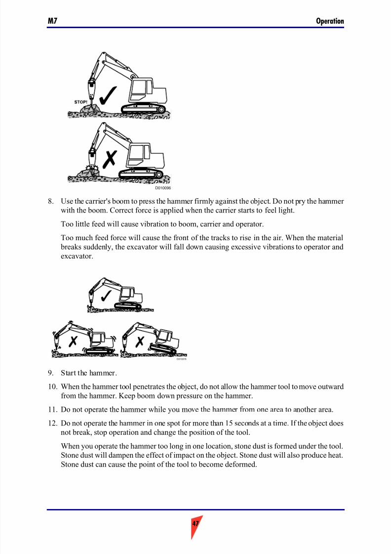
7/26/2019 Operators Manual M7
http://slidepdf.com/reader/full/operators-manual-m7 47/88
47
OperationM7
8. Use the carrier's boom to press the hammer firmly against the object. Do not pry the hammer with the boom. Correct force is applied when the carrier starts to feel light.
Too little feed will cause vibration to boom, carrier and operator.
Too much feed force will cause the front of the tracks to rise in the air. When the material breaks suddenly, the excavator will fall down causing excessive vibrations to operator andexcavator.
9. Start the hammer.
10. When the hammer tool penetrates the object, do not allow the hammer tool to move outwardfrom the hammer. Keep boom down pressure on the hammer.
11. Do not operate the hammer while you move the hammer from one area to another area.
12. Do not operate the hammer in one spot for more than 15 seconds at a time. If the object doesnot break, stop operation and change the position of the tool.
When you operate the hammer too long in one location, stone dust is formed under the tool.Stone dust will dampen the effect of impact on the object. Stone dust will also produce heat.Stone dust can cause the point of the tool to become deformed.
D010096
D010076
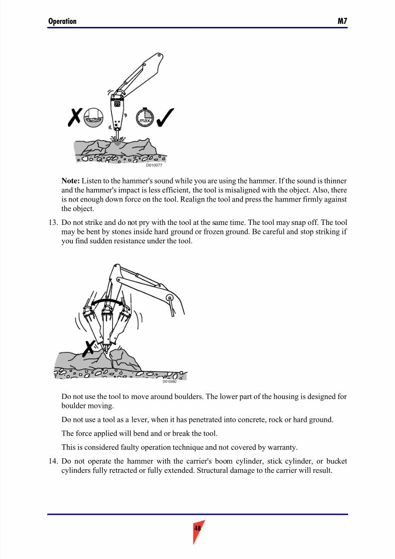
7/26/2019 Operators Manual M7
http://slidepdf.com/reader/full/operators-manual-m7 48/88
Operation M7
48
Note: Listen to the hammer's sound while you are using the hammer. If the sound is thinner and the hammer's impact is less efficient, the tool is misaligned with the object. Also, thereis not enough down force on the tool. Realign the tool and press the hammer firmly againstthe object.
13. Do not strike and do not pry with the tool at the same time. The tool may snap off. The toolmay be bent by stones inside hard ground or frozen ground. Be careful and stop striking if you find sudden resistance under the tool.
Do not use the tool to move around boulders. The lower part of the housing is designed for boulder moving.
Do not use a tool as a lever, when it has penetrated into concrete, rock or hard ground.
The force applied will bend and or break the tool.
This is considered faulty operation technique and not covered by warranty.
14. Do not operate the hammer with the carrier's boom cylinder, stick cylinder, or bucketcylinders fully retracted or fully extended. Structural damage to the carrier will result.
D010077
D010082
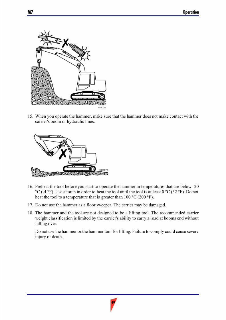
7/26/2019 Operators Manual M7
http://slidepdf.com/reader/full/operators-manual-m7 49/88
49
OperationM7
15. When you operate the hammer, make sure that the hammer does not make contact with thecarrier's boom or hydraulic lines.
16. Preheat the tool before you start to operate the hammer in temperatures that are below -20°C (-4 °F). Use a torch in order to heat the tool until the tool is at least 0 °C (32 °F). Do notheat the tool to a temperature that is greater than 100 °C (200 °F).
17. Do not use the hammer as a floor sweeper. The carrier may be damaged.
18. The hammer and the tool are not designed to be a lifting tool. The recommended carrier weight classification is limited by the carrier's ability to carry a load at booms end without
falling over.Do not use the hammer or the hammer tool for lifting. Failure to comply could cause severeinjury or death.
D010079
D010078
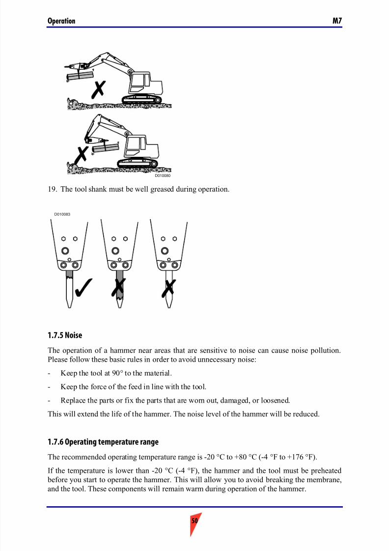
7/26/2019 Operators Manual M7
http://slidepdf.com/reader/full/operators-manual-m7 50/88
Operation M7
50
19. The tool shank must be well greased during operation.
1.7.5 Noise
The operation of a hammer near areas that are sensitive to noise can cause noise pollution.Please follow these basic rules in order to avoid unnecessary noise:
- Keep the tool at 90° to the material.
- Keep the force of the feed in line with the tool.- Replace the parts or fix the parts that are worn out, damaged, or loosened.
This will extend the life of the hammer. The noise level of the hammer will be reduced.
1.7.6 Operating temperature range
The recommended operating temperature range is -20 °C to +80 °C (-4 °F to +176 °F).
If the temperature is lower than -20 °C (-4 °F), the hammer and the tool must be preheated
before you start to operate the hammer. This will allow you to avoid breaking the membrane,and the tool. These components will remain warm during operation of the hammer.
D010080
D010083
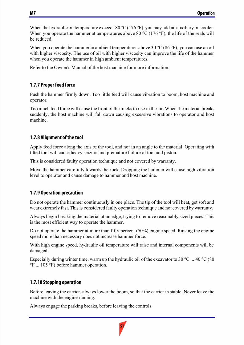
7/26/2019 Operators Manual M7
http://slidepdf.com/reader/full/operators-manual-m7 51/88
51
OperationM7
When the hydraulic oil temperature exceeds 80 °C (176 °F), you may add an auxiliary oil cooler.When you operate the hammer at temperatures above 80 °C (176 °F), the life of the seals will
be reduced.
When you operate the hammer in ambient temperatures above 30 °C (86 °F), you can use an oilwith higher viscosity. The use of oil with higher viscosity can improve the life of the hammer
when you operate the hammer in high ambient temperatures.Refer to the Owner's Manual of the host machine for more information.
1.7.7 Proper feed force
Push the hammer firmly down. Too little feed will cause vibration to boom, host machine andoperator.
Too much feed force will cause the front of the tracks to rise in the air. When the material breakssuddenly, the host machine will fall down causing excessive vibrations to operator and host
machine.
1.7.8 Alignment of the tool
Apply feed force along the axis of the tool, and not in an angle to the material. Operating withtilted tool will cause heavy seizure and premature failure of tool and piston.
This is considered faulty operation technique and not covered by warranty.
Move the hammer carefully towards the rock. Dropping the hammer will cause high vibrationlevel to operator and cause damage to hammer and host machine.
1.7.9 Operation precaution
Do not operate the hammer continuously in one place. The tip of the tool will heat, get soft andwear extremely fast. This is considered faulty operation technique and not covered by warranty.
Always begin breaking the material at an edge, trying to remove reasonably sized pieces. Thisis the most efficient way to operate the hammer.
Do not operate the hammer at more than fifty percent (50%) engine speed. Raising the enginespeed more than necessary does not increase hammer force.
With high engine speed, hydraulic oil temperature will raise and internal components will bedamaged.
Especially during winter time, warm up the hydraulic oil of the excavator to 30 °C ... 40 °C (80°F ... 105 °F) before hammer operation.
1.7.10 Stopping operation
Before leaving the carrier, always lower the boom, so that the carrier is stable. Never leave themachine with the engine running.
Always engage the parking breaks, before leaving the controls.
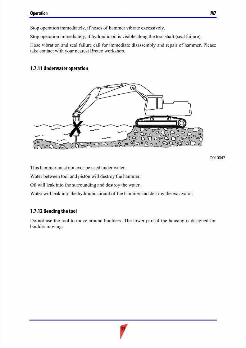
7/26/2019 Operators Manual M7
http://slidepdf.com/reader/full/operators-manual-m7 52/88
Operation M7
52
Stop operation immediately, if hoses of hammer vibrate excessively.
Stop operation immediately, if hydraulic oil is visible along the tool shaft (seal failure).
Hose vibration and seal failure call for immediate disassembly and repair of hammer. Pleasetake contact with your nearest Bretec workshop.
1.7.11 Underwater operation
This hammer must not ever be used under water.
Water between tool and piston will destroy the hammer.
Oil will leak into the surrounding and destroy the water.
Water will leak into the hydraulic circuit of the hammer and destroy the excavator.
1.7.12 Bending the tool
Do not use the tool to move around boulders. The lower part of the housing is designed for boulder moving.
D010047
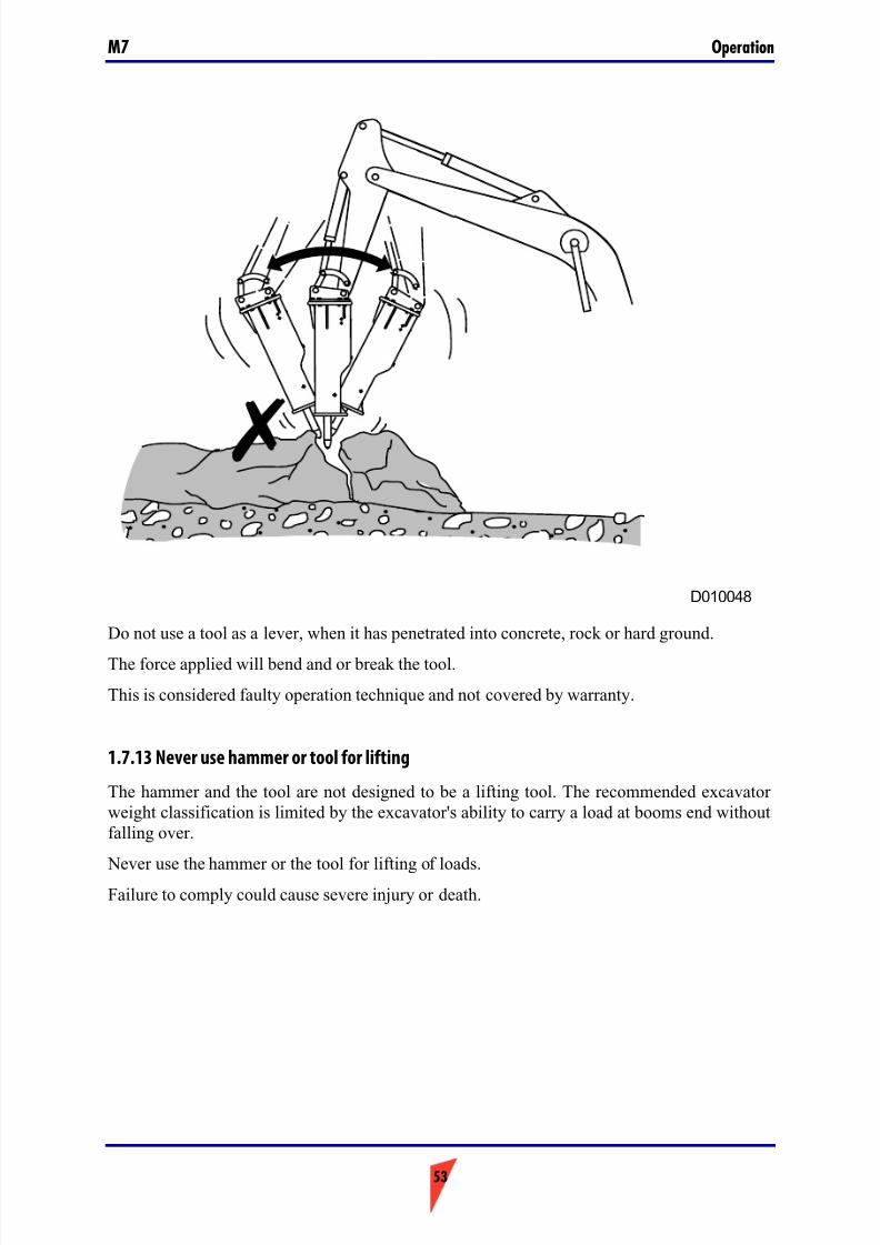
7/26/2019 Operators Manual M7
http://slidepdf.com/reader/full/operators-manual-m7 53/88
53
OperationM7
Do not use a tool as a lever, when it has penetrated into concrete, rock or hard ground.
The force applied will bend and or break the tool.
This is considered faulty operation technique and not covered by warranty.
1.7.13 Never use hammer or tool for lifting
The hammer and the tool are not designed to be a lifting tool. The recommended excavator weight classification is limited by the excavator's ability to carry a load at booms end withoutfalling over.
Never use the hammer or the tool for lifting of loads.Failure to comply could cause severe injury or death.
D010048
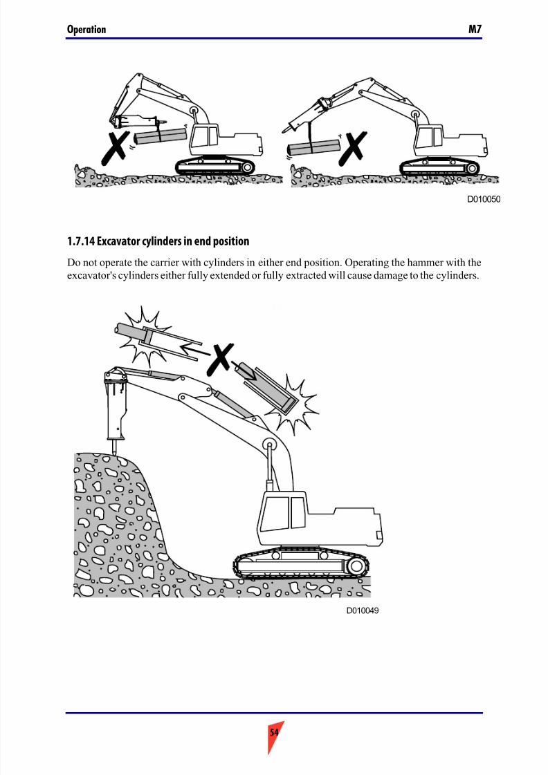
7/26/2019 Operators Manual M7
http://slidepdf.com/reader/full/operators-manual-m7 54/88
Operation M7
54
1.7.14 Excavator cylinders in end position
Do not operate the carrier with cylinders in either end position. Operating the hammer with the
excavator's cylinders either fully extended or fully extracted will cause damage to the cylinders.
D010050
D010049
7/26/2019 Operators Manual M7
http://slidepdf.com/reader/full/operators-manual-m7 55/88
55
LubricationM7
2. Lubrication
7/26/2019 Operators Manual M7
http://slidepdf.com/reader/full/operators-manual-m7 56/88
Lubrication M7
56
2.1. GREASING THE HAMMER
While the hammer is mounted on the carrier, apply down pressure on the tool.
Failure to apply down pressure may allow the grease to enter between tool and piston.Subsequent impact of piston on the grease will generate extremely high pressure and destroy
internal parts of hammer.Pump grease into grease fittings, as indicated on hammer, to apply a proper amount of greaseinside tool bushings.
1. With the hammer mounted on the carrier, apply down pressure to the tool in vertical position.
2. Fill the cavity with proper grease. An NLGI NO. 2 grease must be used for proper lubrication properties.
3. Grease at least every three hours of use. In dry applications, such as demolition of concrete,apply grease more frequently. The tool shaft inside the bushing must never be dry.
4. When installing a new tool, liberally coat the upper 1/3 of the tool with grease beforeinserting.
5. Failure to comply will cause seizure and excessive wear of tool and tool bushing. Excessivewear of tool bush misaligns tool and piston and will cause severe damage to interior partsof the hammer.

7/26/2019 Operators Manual M7
http://slidepdf.com/reader/full/operators-manual-m7 57/88
57
LubricationM7
2.1.1 Recommended greases
■ RAMMER TOOL GREASE, part no. 902045
■ FUCHS Meisselpaste
■ KENDALL Tough TAC
■ KLÜBER Crafloscon C-SG 0 Ultra
■ LE 3751/3752 Almagard varipurpose lubricant
■ SHELL Kuggfett
■ SHELL Albida HLS 2
■ WYNNS GS80
Wear gloves when handling the grease containers. If you get grease onto your skin, wash
it away with water.
R020112
7/26/2019 Operators Manual M7
http://slidepdf.com/reader/full/operators-manual-m7 58/88
Lubrication M7
58
2.2. HYDRAULIC OIL
It is essential, that the viscosity of the oil at operating temperature is within specifications. Theoil viscosity is a guarantee for proper lubrication properties between piston and cylinder. Poor viscosity will cause piston and cylinder to seize and in due time a total failure of hammer internal parts.
Refer to the Operation and Maintenance Manual of the host machine.
Bear in mind that:
- Hydraulic oil degrades quickly in hammer applications and should be replaced morefrequently than in digging applications.
- The operating temperature of the hydraulic oil will vary considerable in summer and inwinter.
- Excavator and hammer plastic parts, such as seals, have a limit to the temperature in whichthey perform properly.
Do not use the oil outside temperature range given in specifications.
If temperature has a tendency to raise to a higher level, reduce heat buildup. Firstly this may be achieved with installing larger diameter pressure and return lines on excavator.
If this is not sufficient, install additional cooler.
Warranty will not apply, where seals are miscoloured due to overheating.
- Contaminated oil is as dangerous as low viscosity oil. Contaminated oil will also damagethe hydraulic pump of the excavator.
Consult your excavator manufacturer on proper filter change intervals and oil changeintervals. Follow the instructions and procedures given.
For special hydraulic fluids, as a rule of thumb any fluid suitable for an excavator will besuitable for your Bretec hammer. You are still advised to consult with your Bretec dealer for achange of hydraulic fluid.
The hammers are test run at factory in standard hydraulic oil and will have small quantities of oil inside.
Consult your excavator manufacturer for proper quality requirements (contamination,oxidation, moisture) of the hydraulic fluids, whether it be special fluids or hydraulic oil.
7/26/2019 Operators Manual M7
http://slidepdf.com/reader/full/operators-manual-m7 59/88
59
MaintenanceM7
3. Maintenance
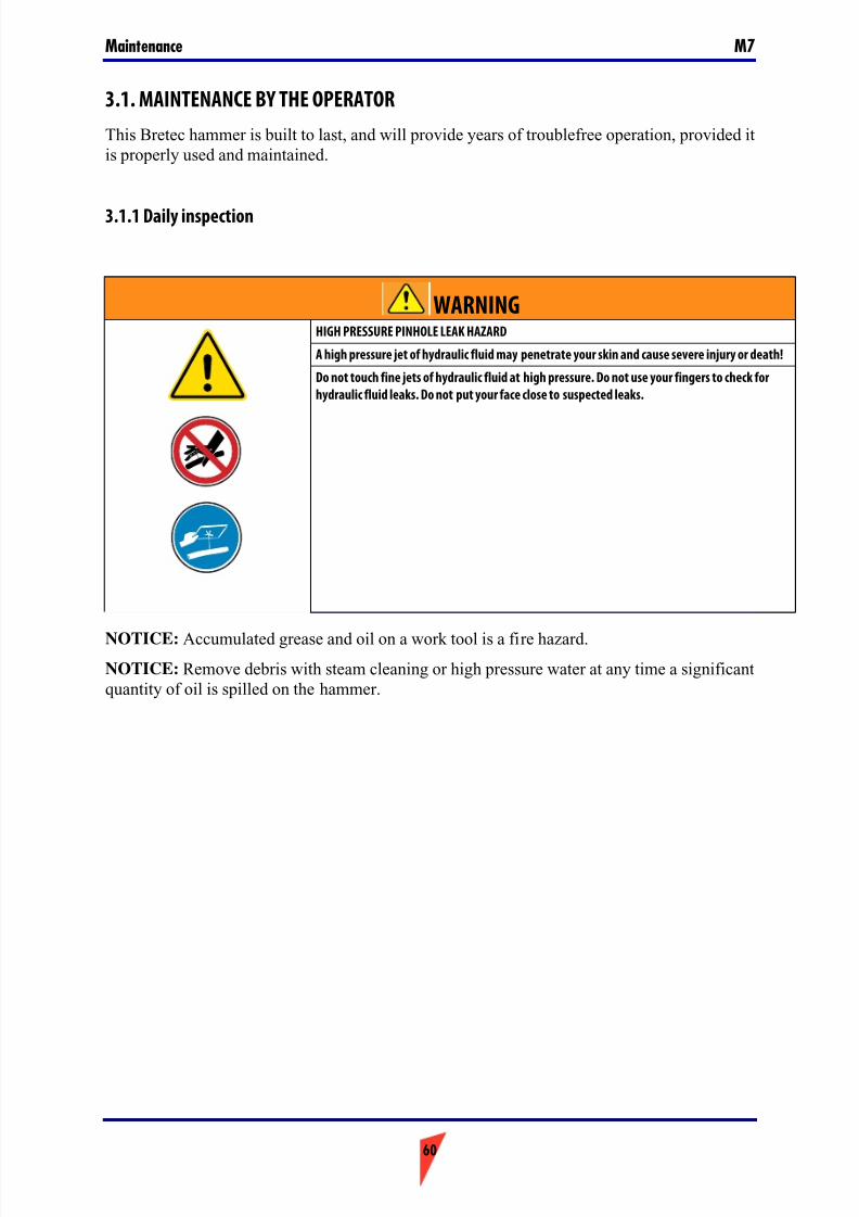
7/26/2019 Operators Manual M7
http://slidepdf.com/reader/full/operators-manual-m7 60/88
Maintenance M7
60
3.1. MAINTENANCE BY THE OPERATOR
This Bretec hammer is built to last, and will provide years of troublefree operation, provided itis properly used and maintained.
3.1.1 Daily inspection
NOTICE: Accumulated grease and oil on a work tool is a fire hazard.NOTICE: Remove debris with steam cleaning or high pressure water at any time a significantquantity of oil is spilled on the hammer.
WARNINGHIGH PRESSURE PINHOLE LEAK HAZARD
A high pressure jet of hydraulic fluid may penetrate your skin and cause severe injury or death!
Do not touch fine jets of hydraulic fluid at high pressure. Do not use your fingers to check for
hydraulic fluid leaks. Do not put your face close to suspected leaks.
7/26/2019 Operators Manual M7
http://slidepdf.com/reader/full/operators-manual-m7 61/88
61
MaintenanceM7
Before starting the hammer, be sure to inspect the hammer referring to the below list:
- Loose, damaged or missing bolts, nuts and fastners must be tightened to proper torque or replaced.
Inspect bracket mounting bolts, tie rods and accumulator bolts.
- Loose hose and pipe fittings must be tightened.Inspect for visible damage to hoses and leakages on hoses and pipes. Check also thehydraulic flanges for proper torque.
Inspect the pipes for the hammer and the oil hoses. If lubrication device is used, check thisas well.
- Hammer oil leaks.
Inspect the connections of the back head and the cylinder. Inspect clearance between fronthead and the tool.
If leakage occurs at hydraulic hose connections, tighten fittings or replace.Other leakages require workshop service. Do not operate the hammer, as this will causeexpensive damage to internal parts (piston, cylinder).
- Inspect the tool and bushing for abnormal wear and cracks.
Replace tool when it is worn out.
Inspect the lower tool bushing for wear, and replace if required.
- Grease the tool each day at startup and 10 pumps every 3 hours using the head grease pump.
- Inspect the hydraulic oil level, and the degree of contamination.
Too little oil may cause a oil heating problem. Contaminated oil will destroy the pump of the excavator. Follow instructions of the excavator manufacturer.
- Inspect the hammer body and housing for missing rubber plugs. Replace, where missing.
- Check the overall condition of the hammer and the hydraulic system.
Perform all repairs before the hammer is put into service.
Check safety signs and labels. Replace the safety signs and the labels when the safety signsand the labels are damaged. Replace the safety signs and the labels when you cannot readthe safety signs and the labels. Replace the safety signs and labels when the safety signs and
labels are missing.
7/26/2019 Operators Manual M7
http://slidepdf.com/reader/full/operators-manual-m7 62/88
Maintenance M7
62
3.2. RELEASING PRESSURE FROM THE HAMMER
1. Stop the carrier engine.2. Operate boom and hammer controls to release any pressure trapped inside hoses.
3. Wait 10 minutes for oil pressure to drop inside hammer.
4. Close hammer inlet and outlet lines. If quick couplers are used, disconnection automaticallycloses hammer lines. If hammer line includes ball valves, please make sure that they areclosed.
Warning! The hydraulic pressure
inside the hammer must always be
released before making anyadjustments or repairs when the
hammer is connected to the carrier.
There may also be pressurized oil
trapped inside the hammer even if
the hammer is disconnected from the
carrier. Release the hydraulic
pressure according to the following
instructions before opening any
plugs or valve covers.
Warning! This procedure does not
release the pressure from thepressure accumulators! Read the
instructions dealing with the
accumulator before disassembling
the hammer.
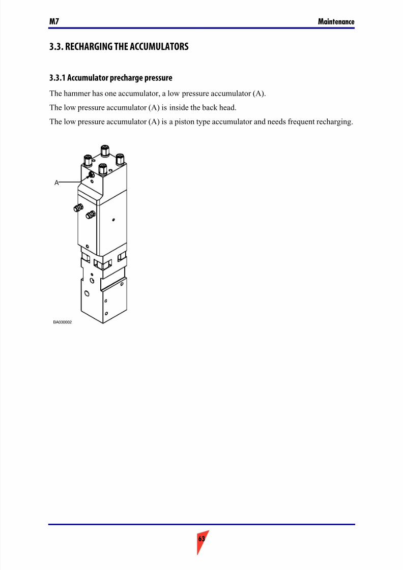
7/26/2019 Operators Manual M7
http://slidepdf.com/reader/full/operators-manual-m7 63/88
63
MaintenanceM7
3.3. RECHARGING THE ACCUMULATORS
3.3.1 Accumulator precharge pressure
The hammer has one accumulator, a low pressure accumulator (A).
The low pressure accumulator (A) is inside the back head.
The low pressure accumulator (A) is a piston type accumulator and needs frequent recharging.
BA030002
A
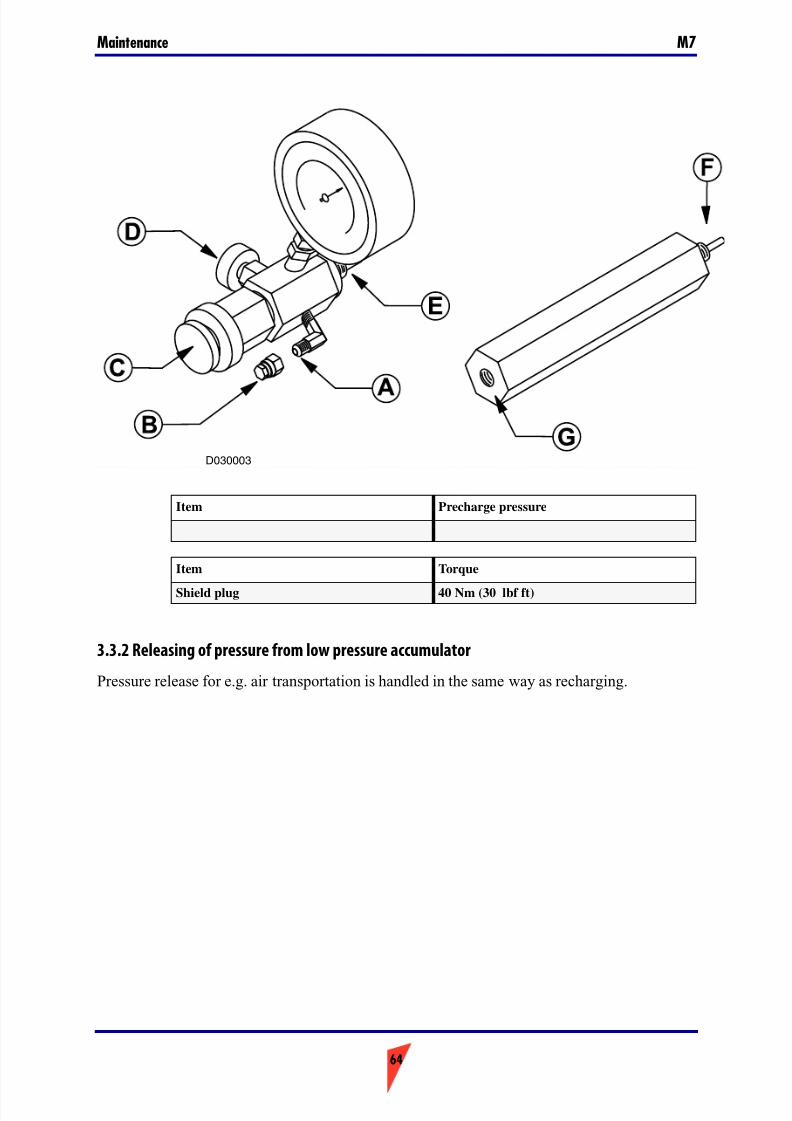
7/26/2019 Operators Manual M7
http://slidepdf.com/reader/full/operators-manual-m7 64/88
Maintenance M7
64
3.3.2 Releasing of pressure from low pressure accumulator
Pressure release for e.g. air transportation is handled in the same way as recharging.
Item Precharge pressure
Item Torque
Shield plug 40 Nm (30 lbf ft)
D030003
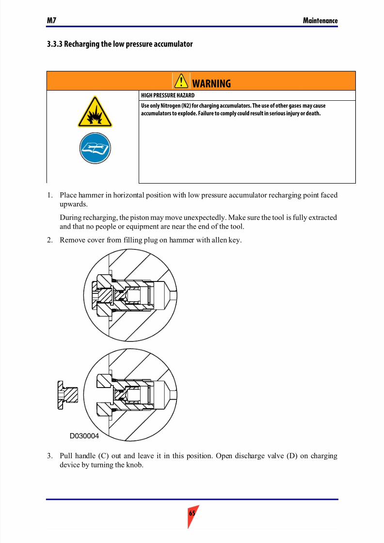
7/26/2019 Operators Manual M7
http://slidepdf.com/reader/full/operators-manual-m7 65/88
65
MaintenanceM7
3.3.3 Recharging the low pressure accumulator
1. Place hammer in horizontal position with low pressure accumulator recharging point facedupwards.
During recharging, the piston may move unexpectedly. Make sure the tool is fully extractedand that no people or equipment are near the end of the tool.
2. Remove cover from filling plug on hammer with allen key.
3. Pull handle (C) out and leave it in this position. Open discharge valve (D) on chargingdevice by turning the knob.
WARNINGHIGH PRESSURE HAZARD
Use only Nitrogen (N2) for charging accumulators. The use of other gases may cause
accumulators to explode. Failure to comply could result in serious injury or death.
D030004
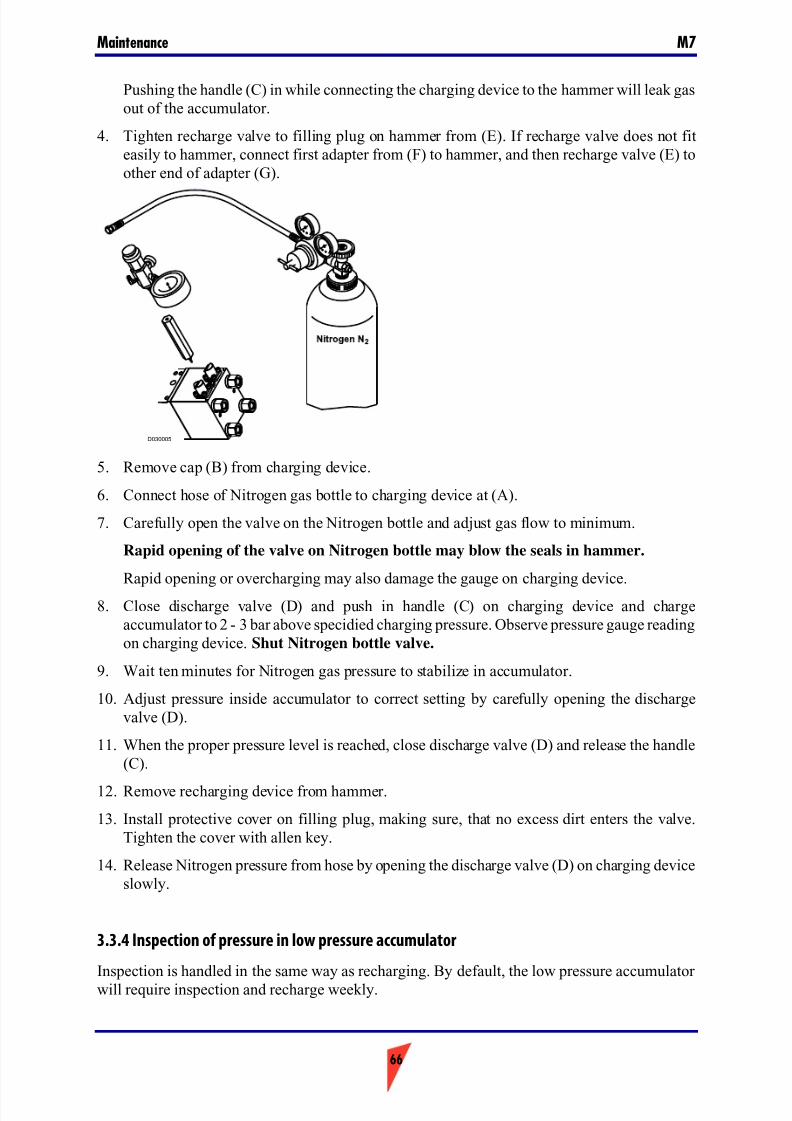
7/26/2019 Operators Manual M7
http://slidepdf.com/reader/full/operators-manual-m7 66/88
Maintenance M7
66
Pushing the handle (C) in while connecting the charging device to the hammer will leak gasout of the accumulator.
4. Tighten recharge valve to filling plug on hammer from (E). If recharge valve does not fiteasily to hammer, connect first adapter from (F) to hammer, and then recharge valve (E) toother end of adapter (G).
5. Remove cap (B) from charging device.
6. Connect hose of Nitrogen gas bottle to charging device at (A).
7. Carefully open the valve on the Nitrogen bottle and adjust gas flow to minimum.
Rapid opening of the valve on Nitrogen bottle may blow the seals in hammer.
Rapid opening or overcharging may also damage the gauge on charging device.
8. Close discharge valve (D) and push in handle (C) on charging device and chargeaccumulator to 2 - 3 bar above specidied charging pressure. Observe pressure gauge readingon charging device. Shut Nitrogen bottle valve.
9. Wait ten minutes for Nitrogen gas pressure to stabilize in accumulator.
10. Adjust pressure inside accumulator to correct setting by carefully opening the dischargevalve (D).
11. When the proper pressure level is reached, close discharge valve (D) and release the handle(C).
12. Remove recharging device from hammer.
13. Install protective cover on filling plug, making sure, that no excess dirt enters the valve.Tighten the cover with allen key.
14. Release Nitrogen pressure from hose by opening the discharge valve (D) on charging deviceslowly.
3.3.4 Inspection of pressure in low pressure accumulator
Inspection is handled in the same way as recharging. By default, the low pressure accumulator will require inspection and recharge weekly.
D030005

7/26/2019 Operators Manual M7
http://slidepdf.com/reader/full/operators-manual-m7 67/88
67
MaintenanceM7
Worn out seals may further reduce the recharging interval. In this case, please change seals atworkshop.
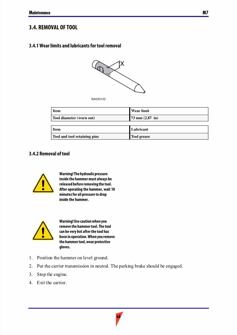
7/26/2019 Operators Manual M7
http://slidepdf.com/reader/full/operators-manual-m7 68/88
Maintenance M7
68
3.4. REMOVAL OF TOOL
3.4.1 Wear limits and lubricants for tool removal
3.4.2 Removal of tool
1. Position the hammer on level ground.
2. Put the carrier transmission in neutral. The parking brake should be engaged.
3. Stop the engine.
4. Exit the carrier.
Item Wear limit
Tool diameter (worn out) 73 mm (2.87 in)
Item Lubricant
Tool and tool retaining pins Tool grease
Warning! The hydraulic pressureinside the hammer must always be
released before removing the tool.
After operating the hammer, wait 10
minutes for oil pressure to drop
inside the hammer.
Warning! Use caution when you
remove the hammer tool. The tool
can be very hot after the tool has
been in operation. When you remove
the hammer tool, wear protective
gloves.
BA030122
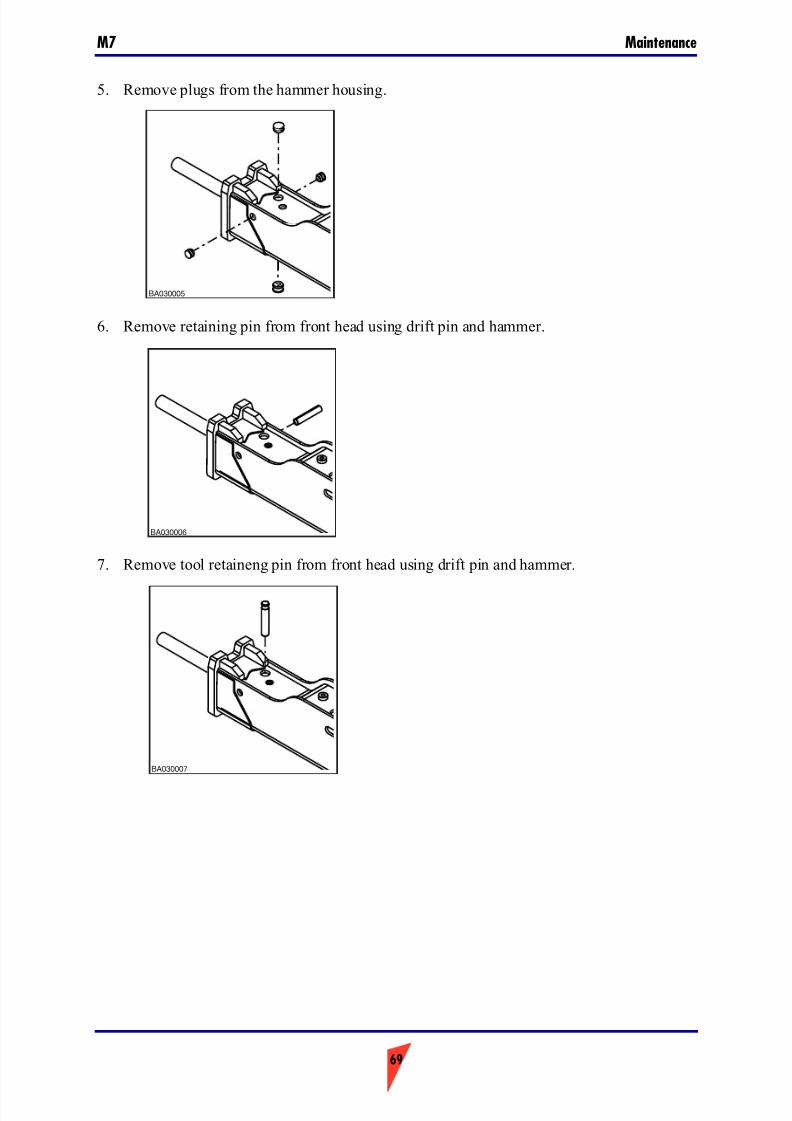
7/26/2019 Operators Manual M7
http://slidepdf.com/reader/full/operators-manual-m7 69/88
69
MaintenanceM7
5. Remove plugs from the hammer housing.
6. Remove retaining pin from front head using drift pin and hammer.
7. Remove tool retaineng pin from front head using drift pin and hammer.
BA030005
BA030006
BA030007

7/26/2019 Operators Manual M7
http://slidepdf.com/reader/full/operators-manual-m7 70/88
Maintenance M7
70
8. Remove tool. When you remove the hammer tool, wear protective gloves.
9. If necessary, use a suitable lifting device to remove the tool. Refer to table below for theweight of the tool.
10. After you have removed the tool, inspect the hammer tool and lower tool bushing for wear.
11. Refer to table below for the wear limit for tool and lower tool bushings. If you have toreplaced lower tool bushing, see the removal and installation of lower tool bushing.
3.4.3 Installation of tool
1. Clean tool.
2. Apply tool grease to tool.
3. Install tool.
4. Apply grease to tool retaining pin.
BA030008
BA030012
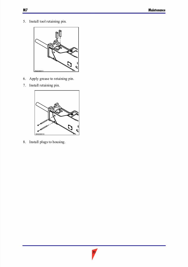
7/26/2019 Operators Manual M7
http://slidepdf.com/reader/full/operators-manual-m7 71/88
71
MaintenanceM7
5. Install tool retaining pin.
6. Apply grease to retaining pin.
7. Install retaining pin.
8. Install plugs to housing.
BA030011
BA030010
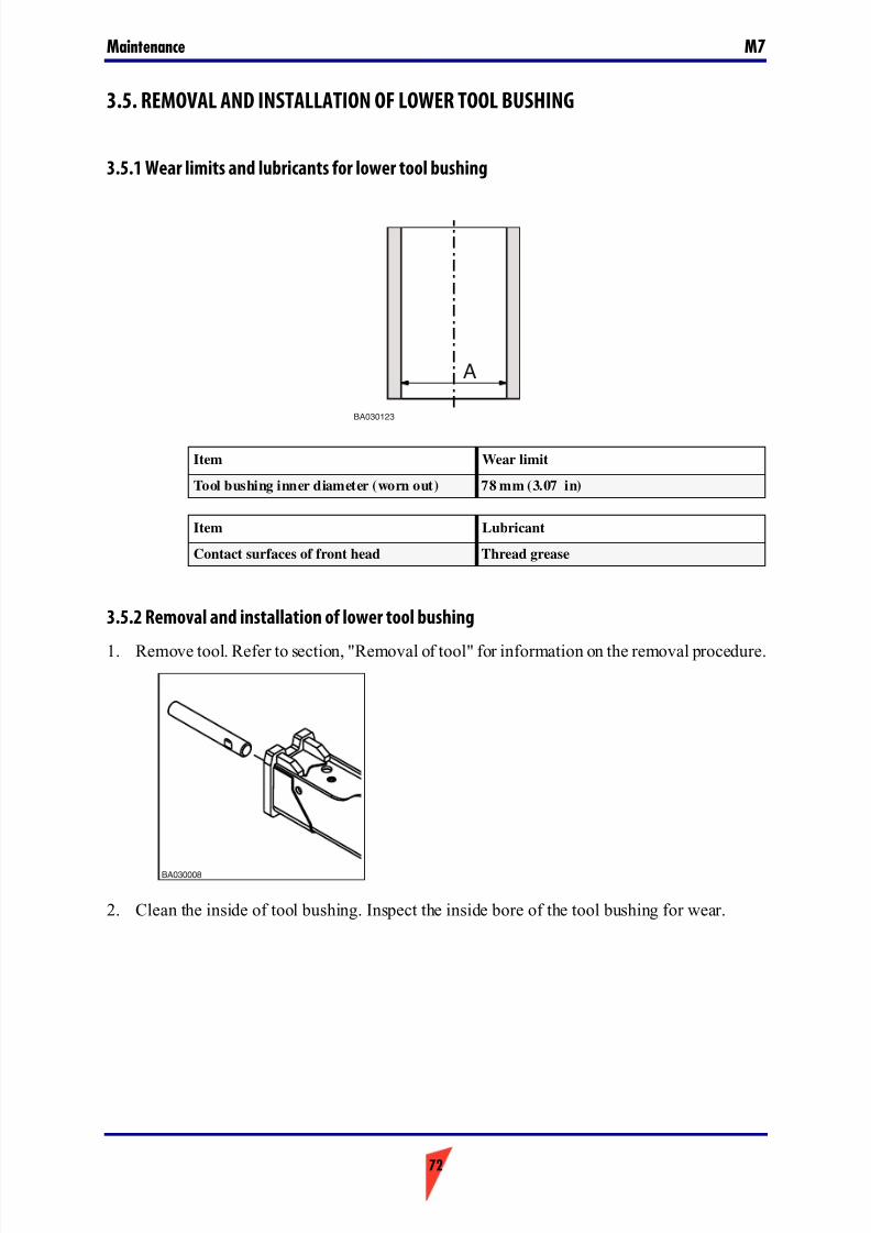
7/26/2019 Operators Manual M7
http://slidepdf.com/reader/full/operators-manual-m7 72/88
Maintenance M7
72
3.5. REMOVAL AND INSTALLATION OF LOWER TOOL BUSHING
3.5.1 Wear limits and lubricants for lower tool bushing
3.5.2 Removal and installation of lower tool bushing
1. Remove tool. Refer to section, "Removal of tool" for information on the removal procedure.
2. Clean the inside of tool bushing. Inspect the inside bore of the tool bushing for wear.
Item Wear limit
Tool bushing inner diameter (worn out) 78 mm (3.07 in)
Item Lubricant
Contact surfaces of front head Thread grease
BA030123
A
BA030008
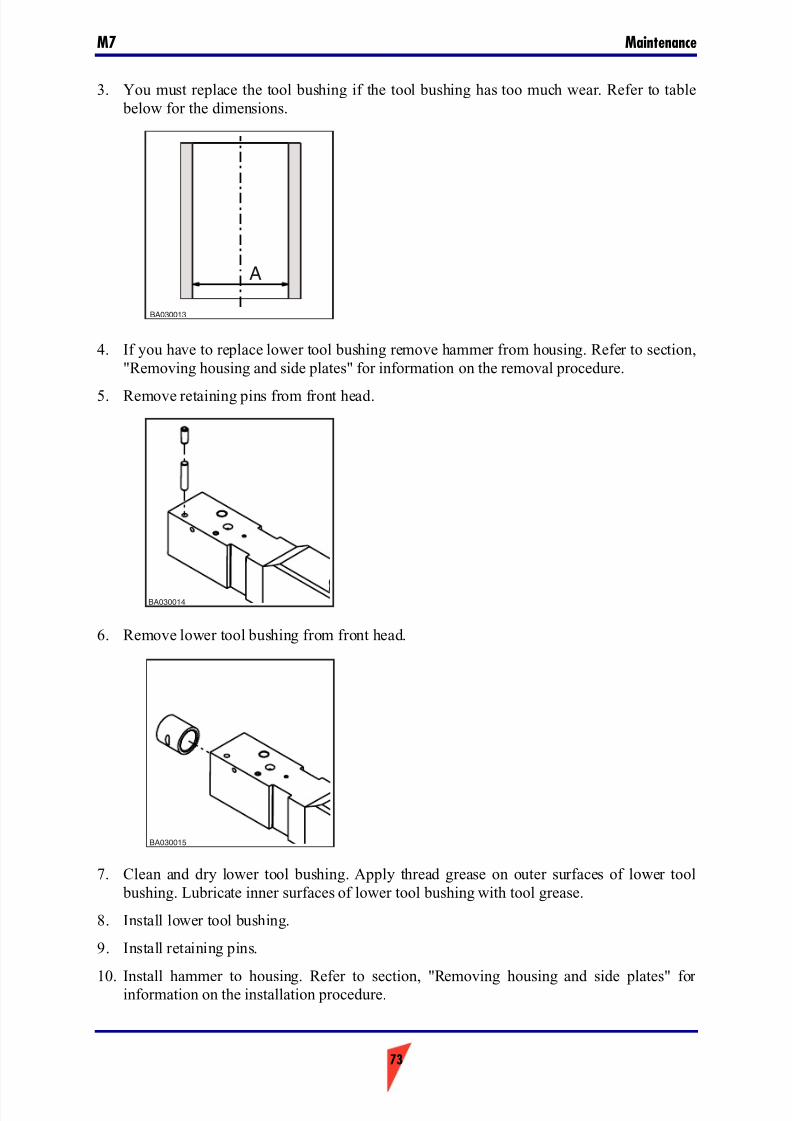
7/26/2019 Operators Manual M7
http://slidepdf.com/reader/full/operators-manual-m7 73/88
73
MaintenanceM7
3. You must replace the tool bushing if the tool bushing has too much wear. Refer to table below for the dimensions.
4. If you have to replace lower tool bushing remove hammer from housing. Refer to section,"Removing housing and side plates" for information on the removal procedure.
5. Remove retaining pins from front head.
6. Remove lower tool bushing from front head.
7. Clean and dry lower tool bushing. Apply thread grease on outer surfaces of lower tool bushing. Lubricate inner surfaces of lower tool bushing with tool grease.
8. Install lower tool bushing.
9. Install retaining pins.
10. Install hammer to housing. Refer to section, "Removing housing and side plates" for information on the installation procedure.
BA030013
A
BA030014
BA030015
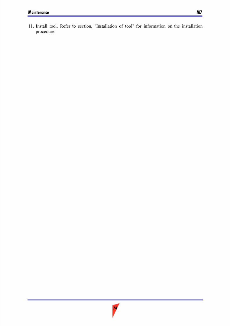
7/26/2019 Operators Manual M7
http://slidepdf.com/reader/full/operators-manual-m7 74/88
Maintenance M7
74
11. Install tool. Refer to section, "Installation of tool" for information on the installation procedure.
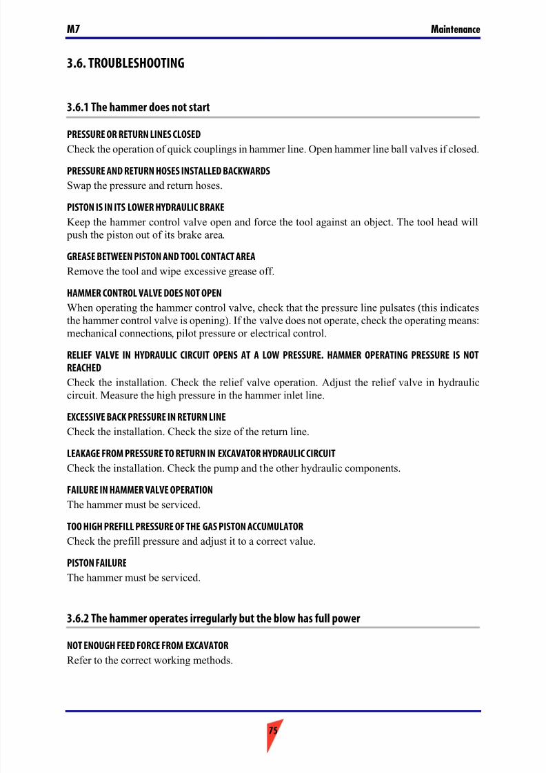
7/26/2019 Operators Manual M7
http://slidepdf.com/reader/full/operators-manual-m7 75/88
75
MaintenanceM7
3.6. TROUBLESHOOTING
3.6.1 The hammer does not start
PRESSURE OR RETURN LINES CLOSEDCheck the operation of quick couplings in hammer line. Open hammer line ball valves if closed.
PRESSURE AND RETURN HOSES INSTALLED BACKWARDS
Swap the pressure and return hoses.
PISTON IS IN ITS LOWER HYDRAULIC BRAKE
Keep the hammer control valve open and force the tool against an object. The tool head will push the piston out of its brake area.
GREASE BETWEEN PISTON AND TOOL CONTACT AREA
Remove the tool and wipe excessive grease off.
HAMMER CONTROL VALVE DOES NOT OPEN
When operating the hammer control valve, check that the pressure line pulsates (this indicatesthe hammer control valve is opening). If the valve does not operate, check the operating means:mechanical connections, pilot pressure or electrical control.
RELIEF VALVE IN HYDRAULIC CIRCUIT OPENS AT A LOW PRESSURE. HAMMER OPERATING PRESSURE IS NOT
REACHED
Check the installation. Check the relief valve operation. Adjust the relief valve in hydrauliccircuit. Measure the high pressure in the hammer inlet line.
EXCESSIVE BACK PRESSURE IN RETURN LINE
Check the installation. Check the size of the return line.
LEAKAGE FROM PRESSURE TO RETURN IN EXCAVATOR HYDRAULIC CIRCUIT
Check the installation. Check the pump and the other hydraulic components.
FAILURE IN HAMMER VALVE OPERATION
The hammer must be serviced.
TOO HIGH PREFILL PRESSURE OF THE GAS PISTON ACCUMULATOR
Check the prefill pressure and adjust it to a correct value.
PISTON FAILURE
The hammer must be serviced.
3.6.2 The hammer operates irregularly but the blow has full power
NOT ENOUGH FEED FORCE FROM EXCAVATOR
Refer to the correct working methods.
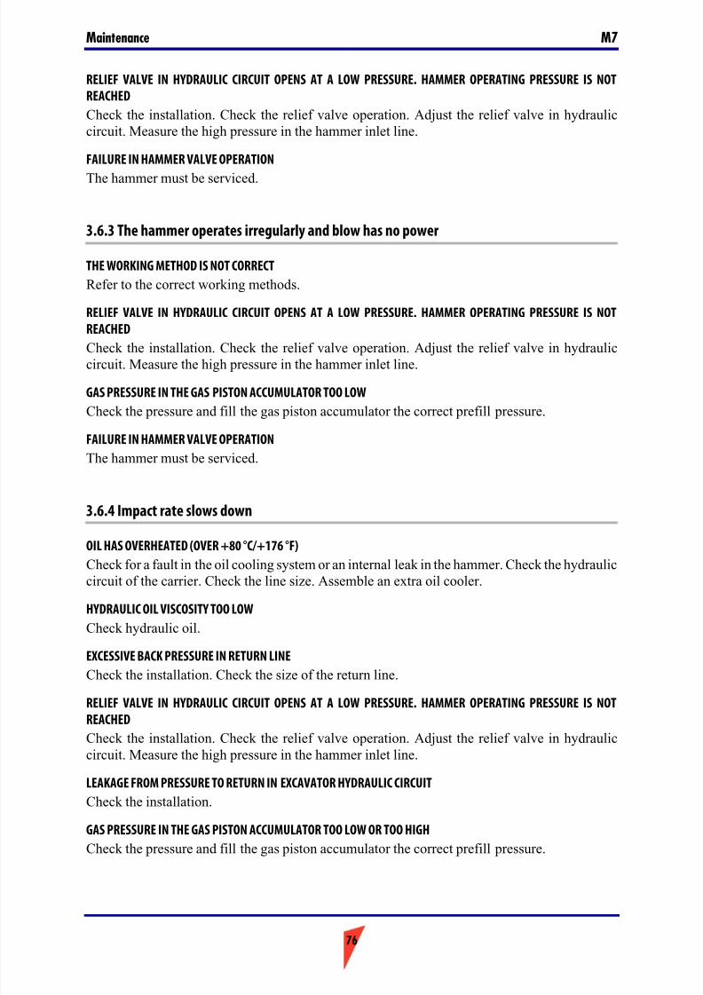
7/26/2019 Operators Manual M7
http://slidepdf.com/reader/full/operators-manual-m7 76/88
Maintenance M7
76
RELIEF VALVE IN HYDRAULIC CIRCUIT OPENS AT A LOW PRESSURE. HAMMER OPERATING PRESSURE IS NOT
REACHED
Check the installation. Check the relief valve operation. Adjust the relief valve in hydrauliccircuit. Measure the high pressure in the hammer inlet line.
FAILURE IN HAMMER VALVE OPERATION
The hammer must be serviced.
3.6.3 The hammer operates irregularly and blow has no power
THE WORKING METHOD IS NOT CORRECT
Refer to the correct working methods.
RELIEF VALVE IN HYDRAULIC CIRCUIT OPENS AT A LOW PRESSURE. HAMMER OPERATING PRESSURE IS NOT
REACHED
Check the installation. Check the relief valve operation. Adjust the relief valve in hydrauliccircuit. Measure the high pressure in the hammer inlet line.
GAS PRESSURE IN THE GAS PISTON ACCUMULATOR TOO LOW
Check the pressure and fill the gas piston accumulator the correct prefill pressure.
FAILURE IN HAMMER VALVE OPERATION
The hammer must be serviced.
3.6.4 Impact rate slows down
OIL HAS OVERHEATED (OVER +80 °C/+176 °F)
Check for a fault in the oil cooling system or an internal leak in the hammer. Check the hydrauliccircuit of the carrier. Check the line size. Assemble an extra oil cooler.
HYDRAULIC OIL VISCOSITY TOO LOW
Check hydraulic oil.
EXCESSIVE BACK PRESSURE IN RETURN LINE
Check the installation. Check the size of the return line.
RELIEF VALVE IN HYDRAULIC CIRCUIT OPENS AT A LOW PRESSURE. HAMMER OPERATING PRESSURE IS NOT
REACHED
Check the installation. Check the relief valve operation. Adjust the relief valve in hydrauliccircuit. Measure the high pressure in the hammer inlet line.
LEAKAGE FROM PRESSURE TO RETURN IN EXCAVATOR HYDRAULIC CIRCUIT
Check the installation.
GAS PRESSURE IN THE GAS PISTON ACCUMULATOR TOO LOW OR TOO HIGH
Check the pressure and fill the gas piston accumulator the correct prefill pressure.

7/26/2019 Operators Manual M7
http://slidepdf.com/reader/full/operators-manual-m7 77/88
77
MaintenanceM7
FAILURE IN HAMMER VALVE OPERATION
The hammer must be serviced.
3.6.5 Oil overheats
APPLICATION NOT CORRECT FOR HAMMER
Refer to recommended use and to correct working methods.
COOLING CAPACITY OF THE FACTORY OIL COOLER IS TOO SMALL
Assemble an extra oil cooler.
RELIEF VALVE IN HYDRAULIC CIRCUIT OPENS AT A LOW PRESSURE. HAMMER OPERATING PRESSURE IS NOT
REACHED
Check the installation. Check the relief valve operation. Adjust the relief valve in hydrauliccircuit. Measure the high pressure in the hammer inlet line.
HYDRAULIC OIL VISCOSITY TOO LOW
Check hydraulic oil.
LEAKAGE FROM PRESSURE TO RETURN IN EXCAVATOR HYDRAULIC CIRCUIT
Check the installation. Check the pump and the other hydraulic components.
INTERNAL OIL LEAK IN THE HAMMER
The hammer must be serviced.
EXCESSIVE BACK PRESSURE IN RETURN LINE
Check the installation.
3.6.6 Recurrent tool failure
APPLICATION NOT CORRECT FOR HAMMER
Refer to recommended use and to correct working methods.
ROUGH OPERATING PRACTICES
Refer to recommended use and to correct working methods.
TOOL DOES NOT GET ENOUGH LUBRICANT
Refer to recommended use and to correct working methods.
TOO LONG TOOL
Use shortest tool possible. Refer to recommended use and to correct working methods.
RAPID WEAR OF TOOL
Refer to recommended use and to correct working methods.
7/26/2019 Operators Manual M7
http://slidepdf.com/reader/full/operators-manual-m7 78/88
Maintenance M7
78
3.6.7 Further assistance
FURTHER ASSISTANCE
If further assistance is required, please prepare to answer the following questions before callingyour dealer.
■ Model and serial number ■ Working hours and service history
■ Carrier model
■ Installation: Oil flow, operating pressure and return line pressure if known
■ Application
■ Has the product operated normally before

7/26/2019 Operators Manual M7
http://slidepdf.com/reader/full/operators-manual-m7 79/88
79
SpecificationsM7
4. Specifications
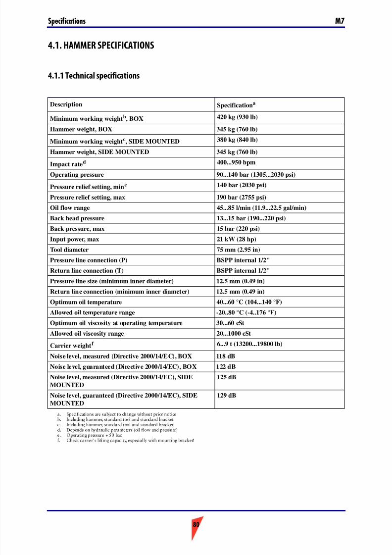
7/26/2019 Operators Manual M7
http://slidepdf.com/reader/full/operators-manual-m7 80/88
Specifications M7
80
4.1. HAMMER SPECIFICATIONS
4.1.1 Technical specifications
Description Specificationa
a. Specifications are subject to change without prior notice
Minimum working weightb, BOX
b. Including hammer, standard tool and standard bracket.
420 kg (930 lb)
Hammer weight, BOX 345 kg (760 lb)
Minimum working weightc, SIDE MOUNTED
c. Including hammer, standard tool and standard bracket.
380 kg (840 lb)
Hammer weight, SIDE MOUNTED 345 kg (760 lb)
Impact rated
d. Depends on hydraulic parameters (oil flow and pressure)
400...950 bpm
Operating pressure 90...140 bar (1305...2030 psi)
Pressure relief setting, mine
e. Operating pressure + 50 bar.
140 bar (2030 psi)
Pressure relief setting, max 190 bar (2755 psi)
Oil flow range 45...85 l/min (11.9...22.5 gal/min)
Back head pressure 13...15 bar (190...220 psi)
Back pressure, max 15 bar (220 psi)
Input power, max 21 kW (28 hp)
Tool diameter 75 mm (2.95 in)
Pressure line connection (P) BSPP internal 1/2"
Return line connection (T) BSPP internal 1/2"
Pressure line size (minimum inner diameter) 12.5 mm (0.49 in)
Return line connection (minimum inner diameter) 12.5 mm (0.49 in)
Optimum oil temperature 40...60 °C (104...140 °F)
Allowed oil temperature range -20..80 °C (-4..176 °F)
Optimum oil viscosity at operating temperature 30...60 cSt
Allowed oil viscosity range 20...1000 cSt
Carrier weightf
f. Check carrier's lifting capacity, especially with mounting bracket!
6...9 t (13200...19800 lb)
Noise level, measured (Directive 2000/14/EC), BOX 118 dB
Noise level, guaranteed (Directive 2000/14/EC), BOX 122 dB
Noise level, measured (Directive 2000/14/EC), SIDE
MOUNTED
125 dB
Noise level, guaranteed (Directive 2000/14/EC), SIDE
MOUNTED
129 dB

7/26/2019 Operators Manual M7
http://slidepdf.com/reader/full/operators-manual-m7 81/88
81
SpecificationsM7
4.1.2 Main dimensions: BOX
1 4 5 1
1 0 7 3
390 420
436
260 325
Ø75
140115
1 3 0
1 0 5
1 0 5
115
Ø23, 12 pcs
BA040002

7/26/2019 Operators Manual M7
http://slidepdf.com/reader/full/operators-manual-m7 82/88
Specifications M7
82
4.1.3 Main dimensions: SIDE MOUNTED
1 5 8 2
9 8 7
5 9 5
3 0 4
3 4 3
260
326 500
733
6 9 9
8 8 3
9 1 8
Ø70
176
Ø75
160
227BA040008

7/26/2019 Operators Manual M7
http://slidepdf.com/reader/full/operators-manual-m7 83/88
83
SpecificationsM7
4.1.4 Mounting bracket
D040005

7/26/2019 Operators Manual M7
http://slidepdf.com/reader/full/operators-manual-m7 84/88
Specifications M7
84
4.2. TOOL SPECIFICATIONS
Tool Part no. Length Weight Diameter
Chisel (A) BA071 750 mm (29.53in)
24 kg (50 lb) 75 mm (2.95in)
Moil point (B) BA073 750 mm (29.53
in)
25 kg (60 lb) 75 mm (2.95
in)
Pyramid (F) BA073K3 750 mm (29.53
in)
25 kg (60 lb) 75 mm (2.95
in)
A B C
BA040005
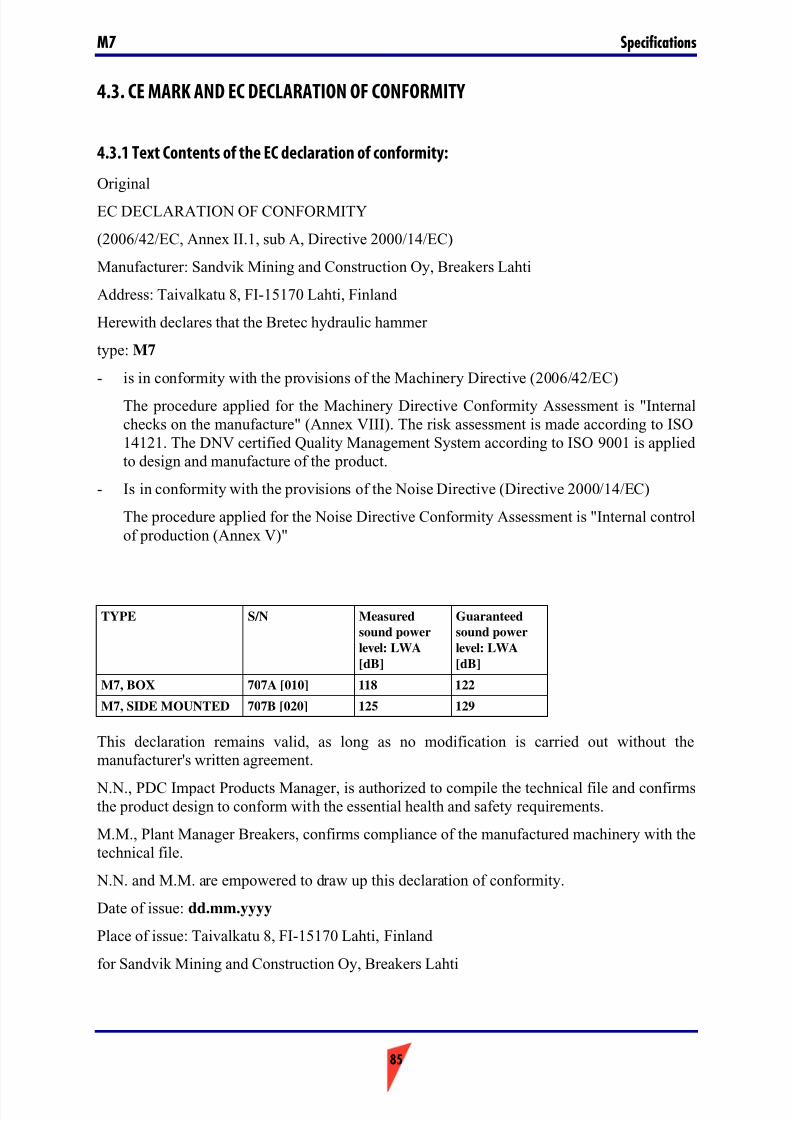
7/26/2019 Operators Manual M7
http://slidepdf.com/reader/full/operators-manual-m7 85/88
85
SpecificationsM7
4.3. CE MARK AND EC DECLARATION OF CONFORMITY
4.3.1 Text Contents of the EC declaration of conformity:
Original
EC DECLARATION OF CONFORMITY
(2006/42/EC, Annex II.1, sub A, Directive 2000/14/EC)
Manufacturer: Sandvik Mining and Construction Oy, Breakers Lahti
Address: Taivalkatu 8, FI-15170 Lahti, Finland
Herewith declares that the Bretec hydraulic hammer
type: M7
- is in conformity with the provisions of the Machinery Directive (2006/42/EC)
The procedure applied for the Machinery Directive Conformity Assessment is "Internalchecks on the manufacture" (Annex VIII). The risk assessment is made according to ISO14121. The DNV certified Quality Management System according to ISO 9001 is appliedto design and manufacture of the product.
- Is in conformity with the provisions of the Noise Directive (Directive 2000/14/EC)
The procedure applied for the Noise Directive Conformity Assessment is "Internal controlof production (Annex V)"
This declaration remains valid, as long as no modification is carried out without themanufacturer's written agreement.
N.N., PDC Impact Products Manager, is authorized to compile the technical file and confirmsthe product design to conform with the essential health and safety requirements.
M.M., Plant Manager Breakers, confirms compliance of the manufactured machinery with thetechnical file.
N.N. and M.M. are empowered to draw up this declaration of conformity.
Date of issue: dd.mm.yyyy
Place of issue: Taivalkatu 8, FI-15170 Lahti, Finland
for Sandvik Mining and Construction Oy, Breakers Lahti
TYPE S/N Measured
sound power
level: LWA
[dB]
Guaranteed
sound power
level: LWA
[dB]
M7, BOX 707A [010] 118 122
M7, SIDE MOUNTED 707B [020] 125 129

7/26/2019 Operators Manual M7
http://slidepdf.com/reader/full/operators-manual-m7 86/88
86

7/26/2019 Operators Manual M7
http://slidepdf.com/reader/full/operators-manual-m7 87/88
87

7/26/2019 Operators Manual M7
http://slidepdf.com/reader/full/operators-manual-m7 88/88