operator's manual manuel d'utilisation … · pb-2155 pb-2455 serial number 001001 &...
TRANSCRIPT

X753001880
04/04
MODEL
PB-2155
PB-2455Serial Number 001001 & UP
OPERATOR'S MANUAL
MANUEL D'UTILISATION
BEDIENUNGSANLEITUNG
MANUALE D'ISTRUZIONI
WARNING, SEE OPERATOR'S MANUAL
LIRE SOIGNEUSEMENT CE MANUEL AVANT TOUTE UTILISATION
ACHTUNG SIEHE BEDIENUNGSANLEITUNG
ATTENZIONE, LEGGETE IL MANUALE D'ISTRUZIONI
ENGLISH
ITALIANO
DEUTSCH
FRANÇAIS
X7531134600

2
WARNING DANGERRead rules for safe operation and instructions carefully. ECHO provides this Operator's Manual which must beread and understood for proper and safe operation.
TABLE OF CONTENTS
Introduction ............................................................... 2
- The Operator's Manual ....................................... 2
Manual Safety Symbols and Important Information .. 3
Safety ......................................................................... 3
- General Description ............................................ 3
- Decals ................................................................. 4
- International Symbols ......................................... 4
- Equipment ........................................................... 5
- Fuel ..................................................................... 5
- Personal Condition and Safety Equipment ......... 6
- Safe Operation .................................................... 7
- Extended Operation/Extreme Conditions ............ 8
Description ................................................................ 9
- Contents ............................................................. 9
Specifications ........................................................... 10
Assembly ................................................................. 10
- Install Blower Pipes .......................................... 10
- Install Vacuum Tube (Optional) ........................ 11
Pre-Operation ........................................................... 12
- Fuel ................................................................... 12
Operation ................................................................. 13
- Starting Cold Engine ......................................... 13
- Starting Warm Engine ....................................... 13
- Stopping Engine ............................................... 13
- Operating Blower .............................................. 14
- Operating Vacuum (Optional) ........................... 15
Maintenance ............................................................ 16
- Maintenance Intervals ...................................... 16
- Air filter ............................................................. 17
- Carburettor Adjustment .................................... 17
- Cooling System ................................................. 18
- Exhaust System ................................................. 19
- Spark Plug ......................................................... 19
- Fuel Filter .......................................................... 20
- Vacuum Bag (Optional) ..................................... 20
- Starter Rope Replacement ................................. 20
Troubleshooting ...................................................... 23
Storage ..................................................................... 24
Declarations ............................................................. 25
Specifications, descriptions and illustrative material in this
literature are as accurate as known at the time of publica-
tion, but are subject to change without notice. Illustrations
may include optional equipment and accessories, and may
not include all standard equipment.
INTRODUCTION
Welcome to the ECHO family. This ECHO product was designed and manufactured to provide long life and on-the-job-dependability. Read and understand this manual. You will find it easy to use and full of helpful operating tips andSAFETY messages.
THE OPERATOR'S MANUAL --contains specifications and information for operation, starting, stop-
ping, maintenance, storage and assembly specific to this product.
3POWER BLOWER
OPERATOR'S MANUAL
MANUAL SAFETY SYMBOLS AND IMPORTANT INFORMATION
Throughout this manual and on the product itself, you will find safety
alerts and helpful, information messages preceded by symbols or key
words. The following is an explanation of those symbols and key words
and what they mean to you.
This symbol accompanied by the words WARNING and
DANGER calls attention to an act or condition that can lead
to serious personal injury to operator and bystanders.
The circle with the slash symbol means whatever is shown
within the circle is prohibited.
SAFETY
GENERAL DESCRIPTION
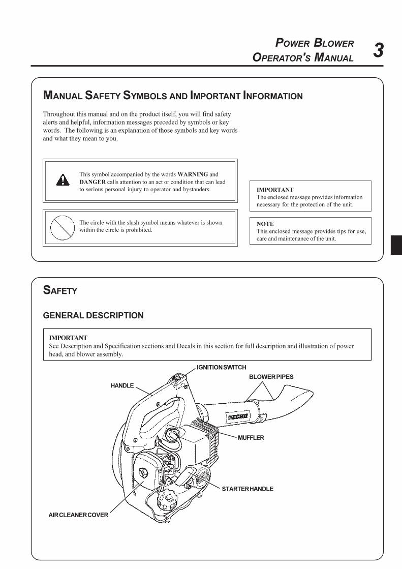
IMPORTANT
See Description and Specification sections and Decals in this section for full description and illustration of power
head, and blower assembly.
HANDLE
IGNITION SWITCH
BLOWER PIPES
MUFFLER
STARTER HANDLE
AIR CLEANER COVER
IMPORTANT
The enclosed message provides information
necessary for the protection of the unit.
NOTE
This enclosed message provides tips for use,
care and maintenance of the unit.
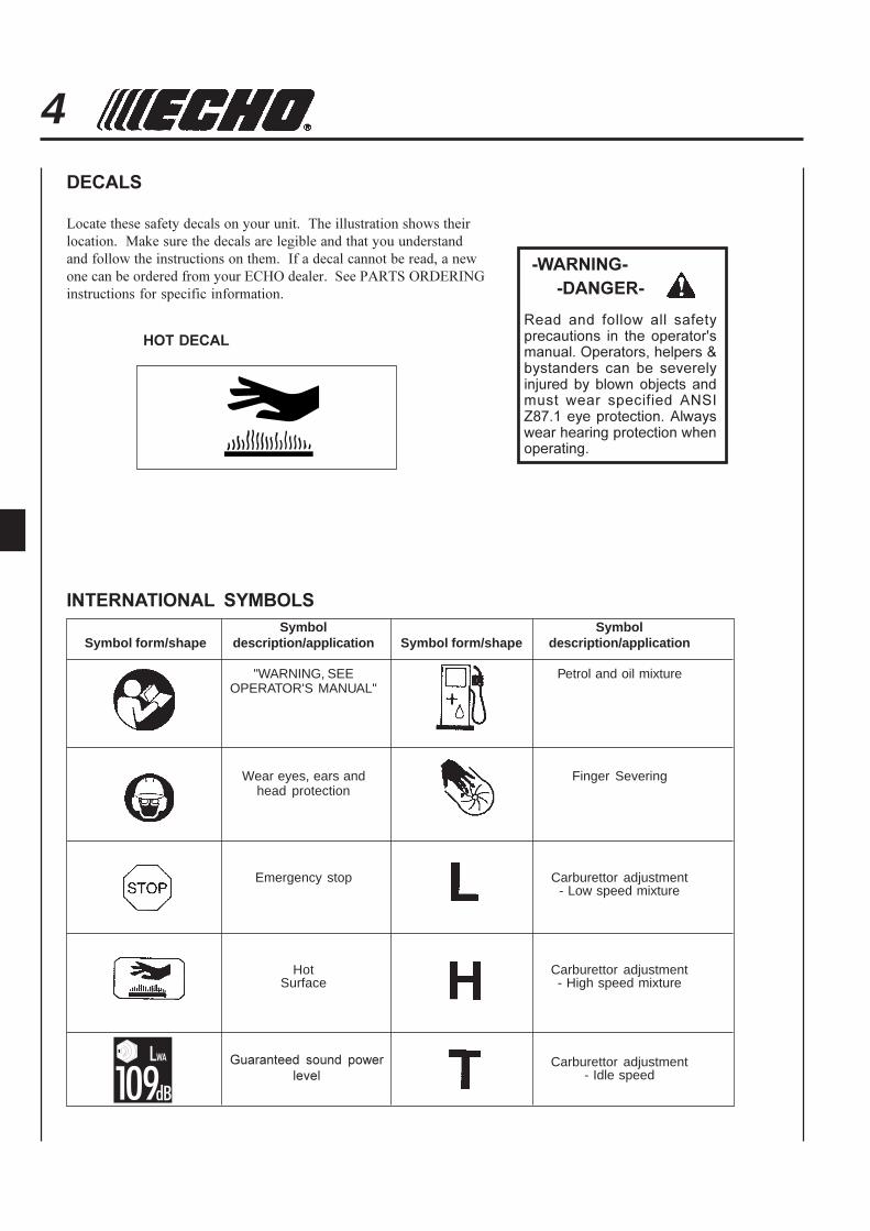
4DECALS
Locate these safety decals on your unit. The illustration shows their
location. Make sure the decals are legible and that you understand
and follow the instructions on them. If a decal cannot be read, a new
one can be ordered from your ECHO dealer. See PARTS ORDERING
instructions for specific information.
Read and follow all safetyprecautions in the operator'smanual. Operators, helpers &bystanders can be severelyinjured by blown objects andmust wear specified ANSIZ87.1 eye protection. Alwayswear hearing protection whenoperating.
-WARNING-
-DANGER-
HOT DECAL
INTERNATIONAL SYMBOLS
Symbol SymbolSymbol form/shape description/application Symbol form/shape description/application
"WARNING, SEE Petrol and oil mixtureOPERATOR'S MANUAL"
Wear eyes, ears and Finger Severinghead protection
Emergency stop Carburettor adjustment- Low speed mixture
Hot Carburettor adjustmentSurface - High speed mixture
Carburettor adjustment- Idle speed
Guaranteed sound power
level
5POWER BLOWER
OPERATOR'S MANUAL
EQUIPMENT
Before operation a complete check of the unit must be performed:
- Check unit for loose/missing nuts, bolts and screws. Tighten
and/or replace as needed.
- Inspect fuel lines, tank and area around carburettor for fuel leaks.
DO NOT operate unit if leaks are found.
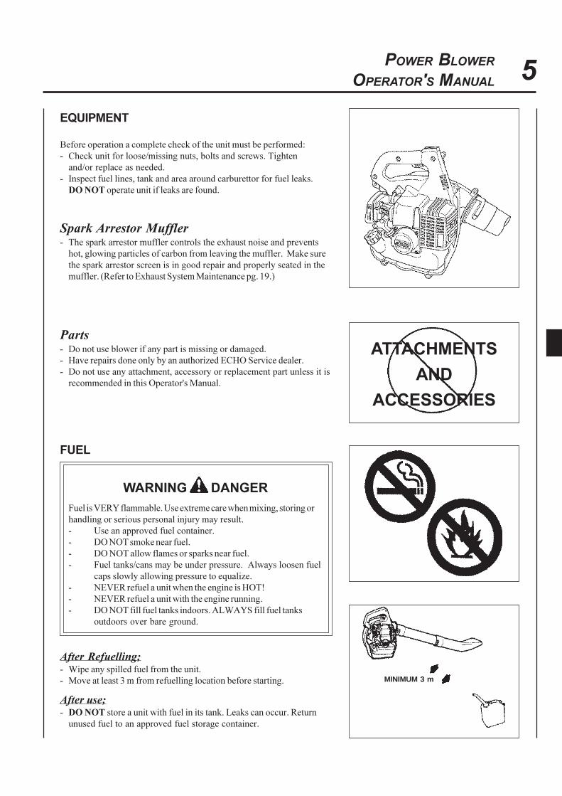
Spark Arrestor Muffler- The spark arrestor muffler controls the exhaust noise and prevents
hot, glowing particles of carbon from leaving the muffler. Make sure
the spark arrestor screen is in good repair and properly seated in the
muffler. (Refer to Exhaust System Maintenance pg. 19.)
Parts- Do not use blower if any part is missing or damaged.
- Have repairs done only by an authorized ECHO Service dealer.
- Do not use any attachment, accessory or replacement part unless it is
recommended in this Operator's Manual.
ATTACHMENTS
AND
ACCESSORIES
FUEL
WARNING DANGER
Fuel is VERY flammable. Use extreme care when mixing, storing or
handling or serious personal injury may result.
- Use an approved fuel container.
- DO NOT smoke near fuel.
- DO NOT allow flames or sparks near fuel.
- Fuel tanks/cans may be under pressure. Always loosen fuel
caps slowly allowing pressure to equalize.
- NEVER refuel a unit when the engine is HOT!
- NEVER refuel a unit with the engine running.
- DO NOT fill fuel tanks indoors. ALWAYS fill fuel tanks
outdoors over bare ground.
After Refuelling;- Wipe any spilled fuel from the unit.
- Move at least 3 m from refuelling location before starting.
After use;- DO NOT store a unit with fuel in its tank. Leaks can occur. Return
unused fuel to an approved fuel storage container.
MINIMUM 3 m

6
Physical Condition --Your judgment and physical dexterity may not be good:
- if you are over tired or sick,
- if you are taking medication,
- if you have taken alcohol or drugs.
Operate unit only if you are physically and mentally well.
Eye Protection --Wear goggles that meet ANSI Z 87.1 eye protection requirements
whenever you operate the blower.
Hand Protection --Wear no-slip, heavy duty work gloves to improve your grip on the
blower handle. Gloves also reduce the transmission of machine
vibration to your hands.
Breathing Protection --Wear a face mask to protect against dust.
Hearing Protection --ECHO recommends wearing hearing protection whenever unit is used.
Proper Clothing --Wear snug fitting, durable clothing;
- Pants should have long legs, shirts with long sleeves.
- DO NOT WEAR SHORTS,
- DO NOT WEAR TIES, SCARVES, JEWELRY.
Wear sturdy work shoes with nonskid soles;
- DO NOT WEAR OPEN TOED SHOES,
- DO NOT OPERATE UNIT BAREFOOTED.
PERSONAL CONDITION AND SAFETY EQUIPMENT
WARNING DANGERPower Blower users risk injury to themselves and others if the power blower is used improperly and
or safety precautions are not followed. Proper clothing and safety gear must be worn when operating a blower.
7POWER BLOWER
OPERATOR'S MANUAL
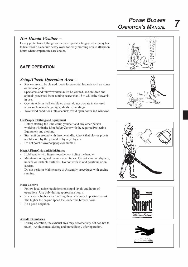
Hot Humid Weather --Heavy protective clothing can increase operator fatigue which may lead
to heat stroke. Schedule heavy work for early morning or late afternoon
hours when temperatures are cooler.
SAFE OPERATION
Setup/Check Operation Area --- Review area to be cleared. Look for potential hazards such as stones
or metal objects.
- Spectators and fellow workers must be warned, and children and
animals prevented from coming nearer than 15 m while the blower is
in use.
- Operate only in well ventilated areas: do not operate in enclosed
areas such as inside garages, sheds or buildings.
- Take wind conditions into account: avoid open doors and windows.
Use Proper Clothing and Equipment
- Before starting the unit, equip yourself and any other person
working within the 15 m Safety Zone with the required Protective
Equipment and clothing.
- Start unit on ground with throttle at idle. Check that blower pipe is
not blocked by the ground or by any objects.
- Do not point blower at people or animals.
Keep A Firm Grip and Solid Stance
- Hold handle with fingers together encircling the handle.
- Maintain footing and balance at all times. Do not stand on slippery,
uneven or unstable surfaces. Do not work in odd positions or on
ladders.
- Do not perform Maintenance or Assembly procedures with engine
running.
Noise Control
- Follow local noise regulations on sound levels and hours of
operations. Use only during appropriate hours.
- Never use a higher speed setting then necessary to perform a task.
The higher the engine speed the louder the blower noise.
- Be a good neighbor.
Avoid Hot Surfaces
- During operation, the exhaust area may become very hot, too hot to
touch. Avoid contact during and immediately after operation.
15 m
8
EXTENDED OPERATION/EXTREME CONDITIONS
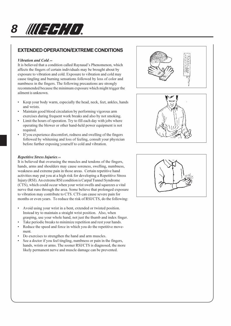
Vibration and Cold --
It is believed that a condition called Raynaud’s Phenomenon, which
affects the fingers of certain individuals may be brought about by
exposure to vibration and cold. Exposure to vibration and cold may
cause tingling and burning sensations followed by loss of color and
numbness in the fingers. The following precautions are strongly
recommended because the minimum exposure which might trigger the
ailment is unknown.
• Keep your body warm, especially the head, neck, feet, ankles, hands
and wrists.
• Maintain good blood circulation by performing vigorous arm
exercises during frequent work breaks and also by not smoking.
• Limit the hours of operation. Try to fill each day with jobs where
operating the blower or other hand-held power equipment is not
required.
• If you experience discomfort, redness and swelling of the fingers
followed by whitening and loss of feeling, consult your physician
before further exposing yourself to cold and vibration.
Repetitive Stress Injuries --
It is believed that overusing the muscles and tendons of the fingers,
hands, arms and shoulders may cause soreness, swelling, numbness,
weakness and extreme pain in those areas. Certain repetitive hand
activities may put you at a high risk for developing a Repetitive Stress
Injury (RSI). An extreme RSI condition is Carpal Tunnel Syndrome
(CTS), which could occur when your wrist swells and squeezes a vital
nerve that runs through the area. Some believe that prolonged exposure
to vibration may contribute to CTS. CTS can cause severe pain for
months or even years. To reduce the risk of RSI/CTS, do the following:
• Avoid using your wrist in a bent, extended or twisted position.
Instead try to maintain a straight wrist position. Also, when
grasping, use your whole hand, not just the thumb and index finger.
• Take periodic breaks to minimize repetition and rest your hands.
• Reduce the speed and force in which you do the repetitive move-
ment.
• Do exercises to strengthen the hand and arm muscles.
• See a doctor if you feel tingling, numbness or pain in the fingers,
hands, wrists or arms. The sooner RSI/CTS is diagnosed, the more
likely permanent nerve and muscle damage can be prevented.

9POWER BLOWER
OPERATOR'S MANUAL
1. SPARK PLUG - Provides spark to ignite fuel mixture.2. THROTTLE POSITION LEVER - Pull back to increase engine speed. Friction washers maintain throttle trigger
setting.3. MUFFLER/SPARK ARRESTER - The spark arrester muffler controls the exhaust noise while the spark arrester
prevents hot, glowing particles of carbon from leaving the muffler.4. FUEL TANK CAP - For closing the fuel tank.5. CHOKE LEVER - Lever is located on right side of the air cleaner. Move lever DOWN to close choke (starting
position) and for emergency stopping. Lift up to open choke (run position).6. AIR CLEANER - Contains replaceable felt element.7. IGNITION SWITCH - "SLIDE SWITCH" mounted on top of handle. Slide forward to start and run. Slide back to
stop.8. THROTTLE TRIGGER - Spring loaded to return to idle when released if throttle position lever is not engaged.9. BLOWER PIPES - Twist lock design.
10. STARTER HANDLE - Pull handle to start the engine. DO NOT let handle snap back or damage to unit will occur.11. PURGE BULB - Pumping purge bulb before starting draws fresh fuel from fuel tank to carburettor replacing air and
old fuel. Before starting, pump repeatedly (normally 3-4 times) until fuel is visible in "Clear" fuel return line.12. OPERATOR'S MANUAL - Included in plastic bag (co-pack). Read before operation and keep in a safe place for
future reference, i.e., operation, maintenance, storage and specifications.
1
4
7
8
9
10
2
7
8
11
6
5
5
3
12
DESCRIPTION
CONTENTS
1- Power Head
1- Blower Pipe Assembly
1- Plastic Bag
1- Operator's Manual

10
PB-2155 PB-2455
Dimensions :Length x Width x Height mm 330 x 215 x 340 330 x 215 x 340Weight kg 4.0 4.3
Engine :Type Air cooled Two stroke single cylinderEngine displacement mL (cm3) 21.2 23.6Maximum power kW 0.51 0.69Engine speed r/min 7,000 - 8,000 7,000 - 8,000Engine idle speed r/min 2,800 - 3,400 2,800 - 3,400Carburettor ZAMA Diaphragm model CIU type with purgeIgnition Flywheel magneto - CDI systemSpark plug CHAMPION RCJ-7YStarter Automatic recoil system
Air Volume with straight pipe : m3/min 8.7 9.0
Fuel : Regular grade petrol. Minimum 89 Octane unleaded petrol is recommended.Do not use fuel containing methyl alcohol or more than 10 % of ethyl alcohol.
Oil Two stroke, air cooled engine oil. ISO-L-EGD Standard (ISO/CD 13738),JASO FC grade and ECHO Premium 50 : 1 oil.
Ratio 50 : 1 (2 %)Tank Capacity : L 0.5Sound Pressure Level :
(Referred to EN27917) LpAav = dB (A) 101 103Guaranteed Sound Power Level :
(2000/14/EC) LWA = dB (A) 107 109Vibration : (Referred to ISO 7916) m/s2 7.2 10.1Blower pipe StandardVacuum kit Optional
ASSEMBLY
WARNING DANGERNever perform maintenance or assembly procedures with engine
running or serious personal injury may result.
INSTALL BLOWER PIPES
1. Remove tube retaining screw from blower housing. Align grooves
in straight pipe with pegs of blower housing and slide pipe onto
housing.
SPECIFICATIONS
11POWER BLOWER
OPERATOR'S MANUAL
Screw
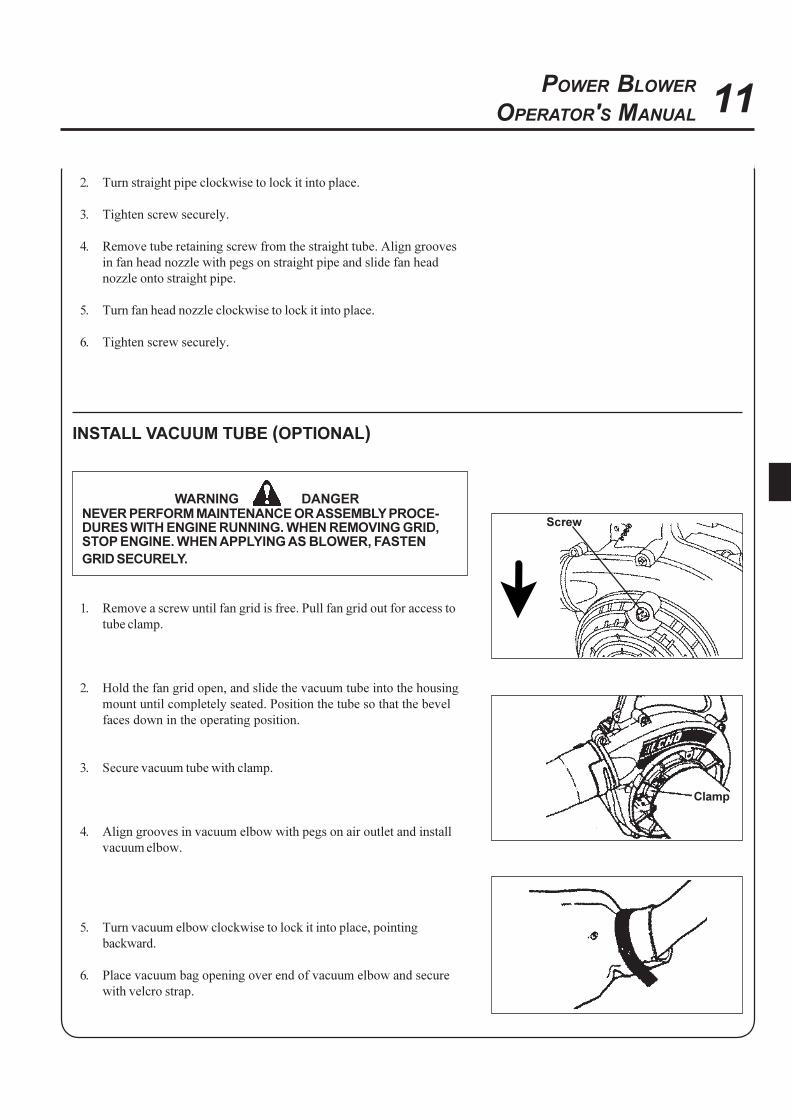
INSTALL VACUUM TUBE (OPTIONAL)
WARNING DANGERNEVER PERFORM MAINTENANCE OR ASSEMBLY PROCE-DURES WITH ENGINE RUNNING. WHEN REMOVING GRID,STOP ENGINE. WHEN APPLYING AS BLOWER, FASTEN
GRID SECURELY.
1. Remove a screw until fan grid is free. Pull fan grid out for access to
tube clamp.
2. Hold the fan grid open, and slide the vacuum tube into the housing
mount until completely seated. Position the tube so that the bevel
faces down in the operating position.
3. Secure vacuum tube with clamp.
4. Align grooves in vacuum elbow with pegs on air outlet and install
vacuum elbow.
5. Turn vacuum elbow clockwise to lock it into place, pointing
backward.
6. Place vacuum bag opening over end of vacuum elbow and secure
with velcro strap.
2. Turn straight pipe clockwise to lock it into place.
3. Tighten screw securely.
4. Remove tube retaining screw from the straight tube. Align grooves
in fan head nozzle with pegs on straight pipe and slide fan head
nozzle onto straight pipe.
5. Turn fan head nozzle clockwise to lock it into place.
6. Tighten screw securely.
Clamp
12
PRE-OPERATION
FUEL
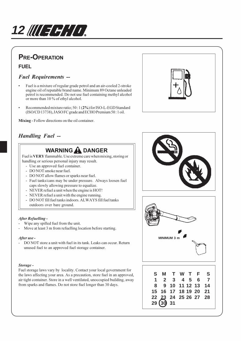
Fuel Requirements --
• Fuel is a mixture of regular grade petrol and an air-cooled 2-strokeengine oil of reputable brand name. Minimum 89 Octane unleadedpetrol is recommended. Do not use fuel containing methyl alcoholor more than 10 % of ethyl alcohol.
• Recommended mixture ratio; 50 : 1 (2%) for ISO-L-EGD Standard(ISO/CD 13738), JASO FC grade and ECHO Premium 50 : 1 oil.
Mixing - Follow directions on the oil container.
Handling Fuel --
WARNING DANGERFuel is VERY flammable. Use extreme care when mixing, storing or
handling or serious personal injury may result.
- Use an approved fuel container.
- DO NOT smoke near fuel.
- DO NOT allow flames or sparks near fuel.
- Fuel tanks/cans may be under pressure. Always loosen fuel
caps slowly allowing pressure to equalize.
- NEVER refuel a unit when the engine is HOT!
- NEVER refuel a unit with the engine running.
- DO NOT fill fuel tanks indoors. ALWAYS fill fuel tanks
outdoors over bare ground.
After Refuelling -
- Wipe any spilled fuel from the unit.
- Move at least 3 m from refuelling location before starting.
After use -
- DO NOT store a unit with fuel in its tank. Leaks can occur. Return
unused fuel to an approved fuel storage container.
Storage -
Fuel storage laws vary by locality. Contact your local government for
the laws affecting your area. As a precaution, store fuel in an approved,
air tight container. Store in a well ventilated, unoccupied building, away
from sparks and flames. Do not store fuel longer than 30 days.
S M T W T F S1 2 3 4 5 6 78 9 10 11 12 13 14
15 16 17 18 19 20 2122 23 24 25 26 27 2829 30 31
MINIMUM 3 m
13POWER BLOWER
OPERATOR'S MANUAL
OPERATION
IMPORTANTCheck unit for loose nuts, bolts and screws daily.
IMPORTANTRecoil starter: Use short pulls - only 1/2-2/3 of rope length forstarting. Do not allow the rope to snap back in. Always hold theunit firmly.
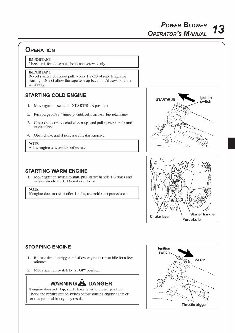
STARTING COLD ENGINE
1. Move ignition switch to START/RUN position.
2. Push purge bulb 3-4 times (or until fuel is visible in fuel return line).
3. Close choke (move choke lever up) and pull starter handle untilengine fires.
4. Open choke and if necessary, restart engine.
NOTEAllow engine to warm up before use.
STARTING WARM ENGINE1. Move ignition switch to start, pull starter handle 1-3 times and
engine should start. Do not use choke.
NOTEIf engine does not start after 4 pulls, use cold start procedures.
STOPPING ENGINE
1. Release throttle trigger and allow engine to run at idle for a fewminutes.
2. Move ignition switch to "STOP" position.
WARNING DANGERIf engine does not stop, shift choke lever to closed position.
Check and repair ignition switch before starting engine again or
serious personal injury may result.
START/RUNIgnitionswitch
Starter handle
Purge bulbChoke lever
STOP
Throttle trigger
Ignitionswitch
14OPERATING BLOWER
WARNING DANGERAlways wear safety glasses, hearing protection and a face filter
mask or serious personal injury may result.
Do not point the blower pipe in the direction of people or pets.
Read the Safety Section carefully.
IMPORTANT
To avoid engine damage due to over revving, do not block
blower pipe.
1. Use only during appropriate hours.
2. Make sure bevel at end of pipe faces downward.
3. Allow the engine to warm up at a fast idle for a few minutes.
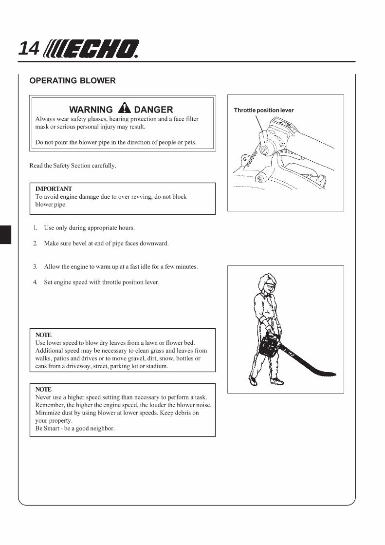
4. Set engine speed with throttle position lever.
NOTE
Use lower speed to blow dry leaves from a lawn or flower bed.
Additional speed may be necessary to clean grass and leaves from
walks, patios and drives or to move gravel, dirt, snow, bottles or
cans from a driveway, street, parking lot or stadium.
NOTE
Never use a higher speed setting than necessary to perform a task.
Remember, the higher the engine speed, the louder the blower noise.
Minimize dust by using blower at lower speeds. Keep debris on
your property.
Be Smart - be a good neighbor.
Throttle position lever

15POWER BLOWER
OPERATOR'S MANUAL
OPERATING VACUUM (OPTION)
WARNING DANGER• Always wear safety glasses and use a face filter mask. (Read the
safe operation section carefully.)
• Do not point the blower pipe in the direction of people or pets.
• Never operate unit without fan grid secured by thumb nut,
otherwise bodily harm may result.
NOTE
Do not block blower pipe to avoid engine damage due to over
speed.
1. Allow the engine to warm up at a fast idle for a few minutes.
2. Engine speed can be easily controlled by throttle trigger with
fingers or throttle position lever.
NOTE
Never use a higher speed setting than necessary to perform a task.
Remember, the higher the engine speed, the louder the blower noise.
NOTE
Use a low speed to blow dry leaves from a lawn or flower bed.
Additional speed may be necessary to clean grass and leaves from
walks, patios and drives or to move gravel, dirt, snow, bottles or cans
from a driveway, street or parking lot.
Throttle position lever
16
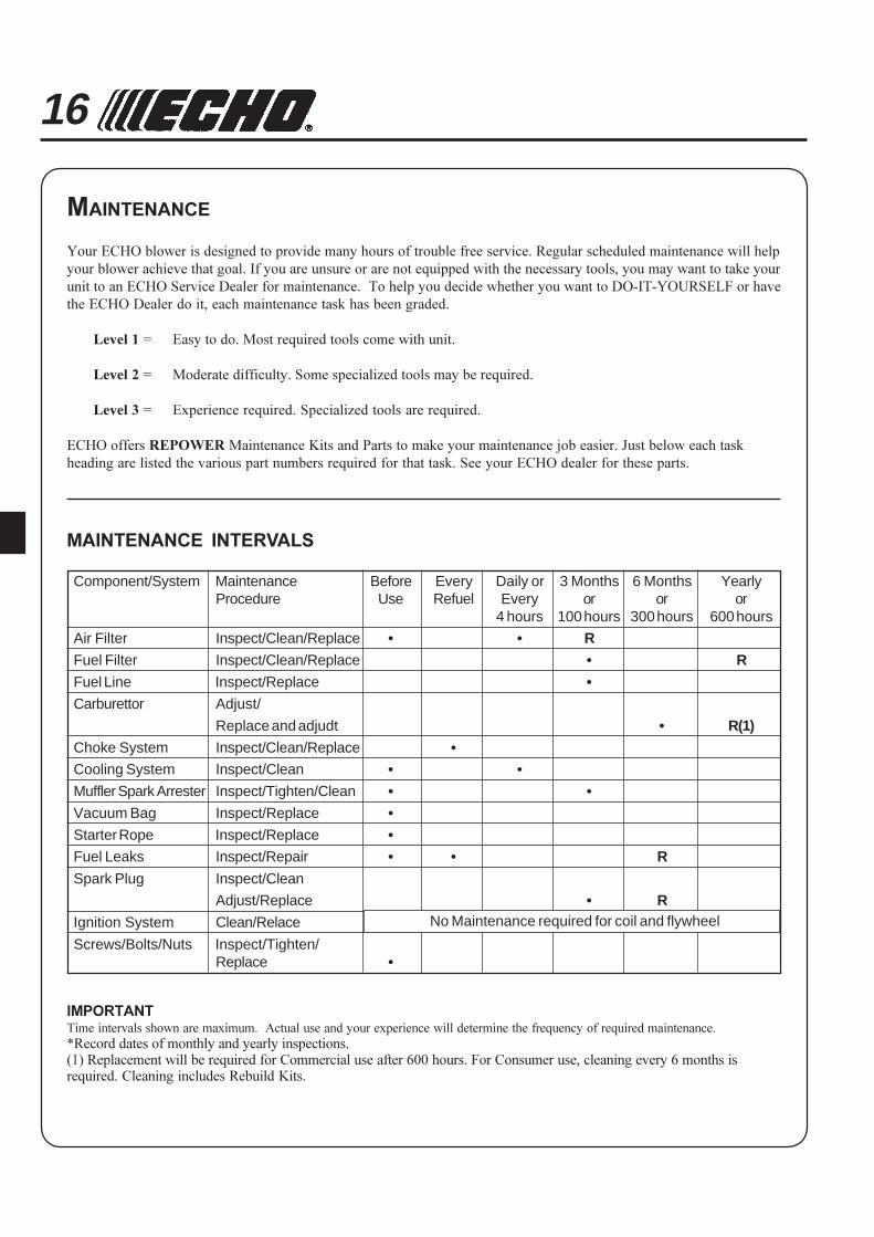
Component/System Maintenance Before Every Daily or 3 Months 6 Months YearlyProcedure Use Refuel Every or or or
4 hours 100 hours 300 hours 600 hours
Air Filter Inspect/Clean/Replace • • R
Fuel Filter Inspect/Clean/Replace • R
Fuel Line Inspect/Replace •
Carburettor Adjust/
Replace and adjudt • R(1)
Choke System Inspect/Clean/Replace •Cooling System Inspect/Clean • •
Muffler Spark Arrester Inspect/Tighten/Clean • •
Vacuum Bag Inspect/Replace •
Starter Rope Inspect/Replace •Fuel Leaks Inspect/Repair • • R
Spark Plug Inspect/Clean
Adjust/Replace • R
Ignition System Clean/Relace
Screws/Bolts/Nuts Inspect/Tighten/Replace •
MAINTENANCE
Your ECHO blower is designed to provide many hours of trouble free service. Regular scheduled maintenance will help
your blower achieve that goal. If you are unsure or are not equipped with the necessary tools, you may want to take your
unit to an ECHO Service Dealer for maintenance. To help you decide whether you want to DO-IT-YOURSELF or have
the ECHO Dealer do it, each maintenance task has been graded.
Level 1 = Easy to do. Most required tools come with unit.
Level 2 = Moderate difficulty. Some specialized tools may be required.
Level 3 = Experience required. Specialized tools are required.
ECHO offers REPOWER Maintenance Kits and Parts to make your maintenance job easier. Just below each task
heading are listed the various part numbers required for that task. See your ECHO dealer for these parts.
MAINTENANCE INTERVALS
IMPORTANTTime intervals shown are maximum. Actual use and your experience will determine the frequency of required maintenance.
*Record dates of monthly and yearly inspections.(1) Replacement will be required for Commercial use after 600 hours. For Consumer use, cleaning every 6 months isrequired. Cleaning includes Rebuild Kits.
No Maintenance required for coil and flywheel

17POWER BLOWER
OPERATOR'S MANUAL
AIR FILTER
Level 1.
Tools required: Cleaning brush, 25 mm or 50 mm medium bristle paint
brush.
Parts required: 90008 REPOWER AIR & FUEL FILTER KIT.
NOTE
Clean daily.
1. Close choke, remove wing nut, air cleaner cover and air filter.
2. Brush dust off filter.
CARBURETTOR ADJUSTMENT - GENERALLevel 2.
Tools required: Screwdriver, tachometer.
Parts required: none.
NOTE
Do not adjust carburetor unless necessary. If you have difficultly,
see your ECHO dealer.
AdjustersIdle Speed Adjuster (T) Control throttle opening at idle.
Low Speed Mixture Adjuster (L) Controls amount of fuel at low
speed and supplementary fuel for
smooth progression from idle to
high speed.
High Speed Mixture Adjuster (H) Controls amount of fuel at full
throttle
Before AdjustmentCheck that:
- Air filter is clean and properly installed.
- Spark arrestor screen and exhaust port are free of carbon
- Blower pipes are installed
Initial Adjustment1. With engine off, turn H adjuster anticlockwise to stop.
2. Turn L adjuster midway between stops.
3. Turn T adjuster until tip of adjuster just touches throttle plate;
then turn three turns clockwise.
H
T
L

18Final Adjustment
IMPORTANT
Limiter caps prevent exceeding emission limits and over rich
adjustment, but not over lean adjustment, which can cause
engine failure: Do not exceed recommended high speed engine
rev during operation, or for long periods during adjustment.
1. Start engine, run at idle for one minute.
2. Complete warm up by running at full throttle for 5 minutes,
operating choke twice to clear air from carburettor chambers.
3. Run at idle and accelerate to check for smooth transition from idle
to high speed; if engine hesitates, turn L adjuster anticlockwise 1/8
turn at a time until acceleration is smooth.
4. Adjust T adjuster to 3,000 r/min, using tachometer.
COOLING SYSTEMS
Level 2.
Tools required: 19 mm Spark Plug deep socket, 3 mm Allen wrench,
Phillips Screwdriver, Pointed Wood Stick, Cleaning Brush, 25 mm - 50
mm medium bristle paint brush.
Parts Required: None if you are careful.
IMPORTANT
To prevent overheating and engine seizure, cooling air comes
through the grille and is pushed by a cooling fan through the
cylinder fin area to an opening in the front of the engine cover,
taking away combustion heat. The grille and cylinder fins must be
kept clean of grass, dust and any debris. Engine failure due to lack
of this "Normal Maintenance" is not covered by warranty.
Cleaning GrilleRemove accumulated debris from crankcase intake grille above the fuel
tank.
Cleaning Cylinder Fins1. Remove spark plug.
2. Remove engine cover (seven screws) and clean cylinder fins to
allow cooling air to pass freely.
INTAKE
GRILLE
NOTE
When there is some trouble with the carburettor, contact your
distributor or dealer.
19POWER BLOWER
OPERATOR'S MANUAL
EXHAUST SYSTEM
Level 3.
Tools Required: Phillips Screwdriver. Scrench. 10 mm Open end
wrench. Soft metal brush. Wooden carbon scraper. 3 mm Allen
wrench, 4 mm Allen wrench.
Parts Required: Spark arrester screen, gasket.
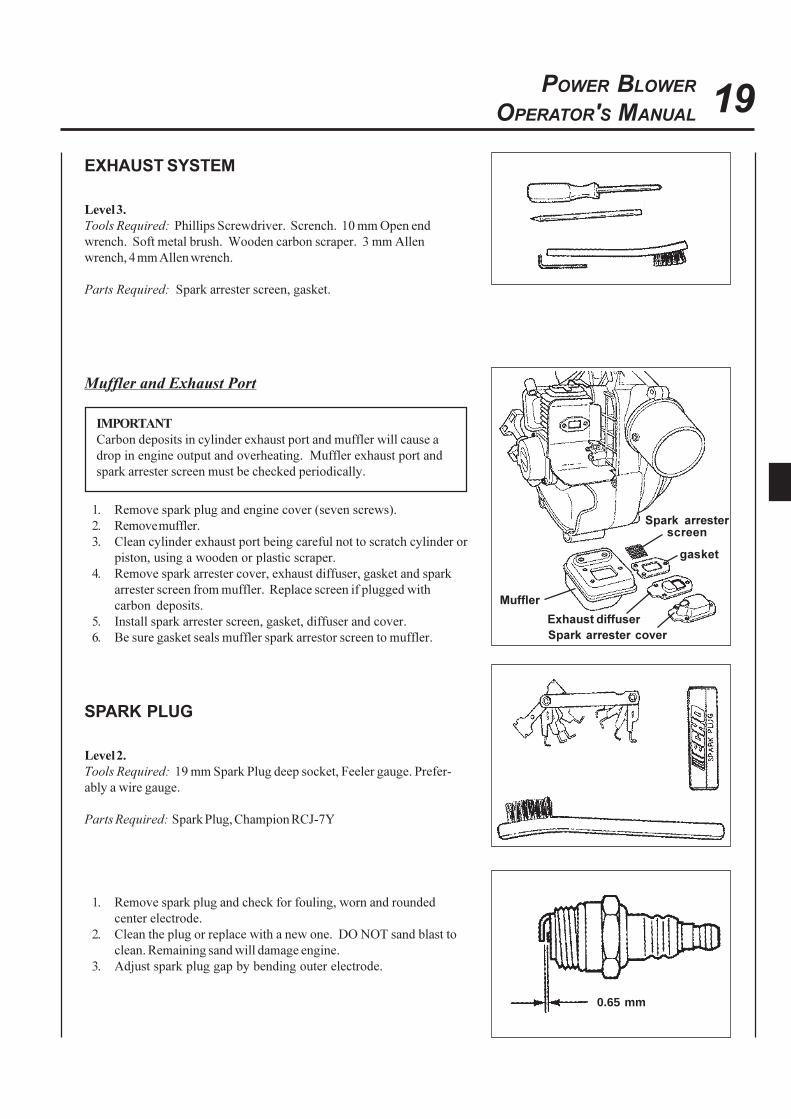
Muffler and Exhaust Port
IMPORTANT
Carbon deposits in cylinder exhaust port and muffler will cause a
drop in engine output and overheating. Muffler exhaust port and
spark arrester screen must be checked periodically.
1. Remove spark plug and engine cover (seven screws).
2. Remove muffler.
3. Clean cylinder exhaust port being careful not to scratch cylinder or
piston, using a wooden or plastic scraper.
4. Remove spark arrester cover, exhaust diffuser, gasket and spark
arrester screen from muffler. Replace screen if plugged with
carbon deposits.
5. Install spark arrester screen, gasket, diffuser and cover.
6. Be sure gasket seals muffler spark arrestor screen to muffler.
SPARK PLUG
Level 2.
Tools Required: 19 mm Spark Plug deep socket, Feeler gauge. Prefer-
ably a wire gauge.
Parts Required: Spark Plug, Champion RCJ-7Y
1. Remove spark plug and check for fouling, worn and rounded
center electrode.
2. Clean the plug or replace with a new one. DO NOT sand blast to
clean. Remaining sand will damage engine.
3. Adjust spark plug gap by bending outer electrode.
0.65 mm
Spark arrester cover
Exhaust diffuser
Spark arresterscreen
gasket
Muffler
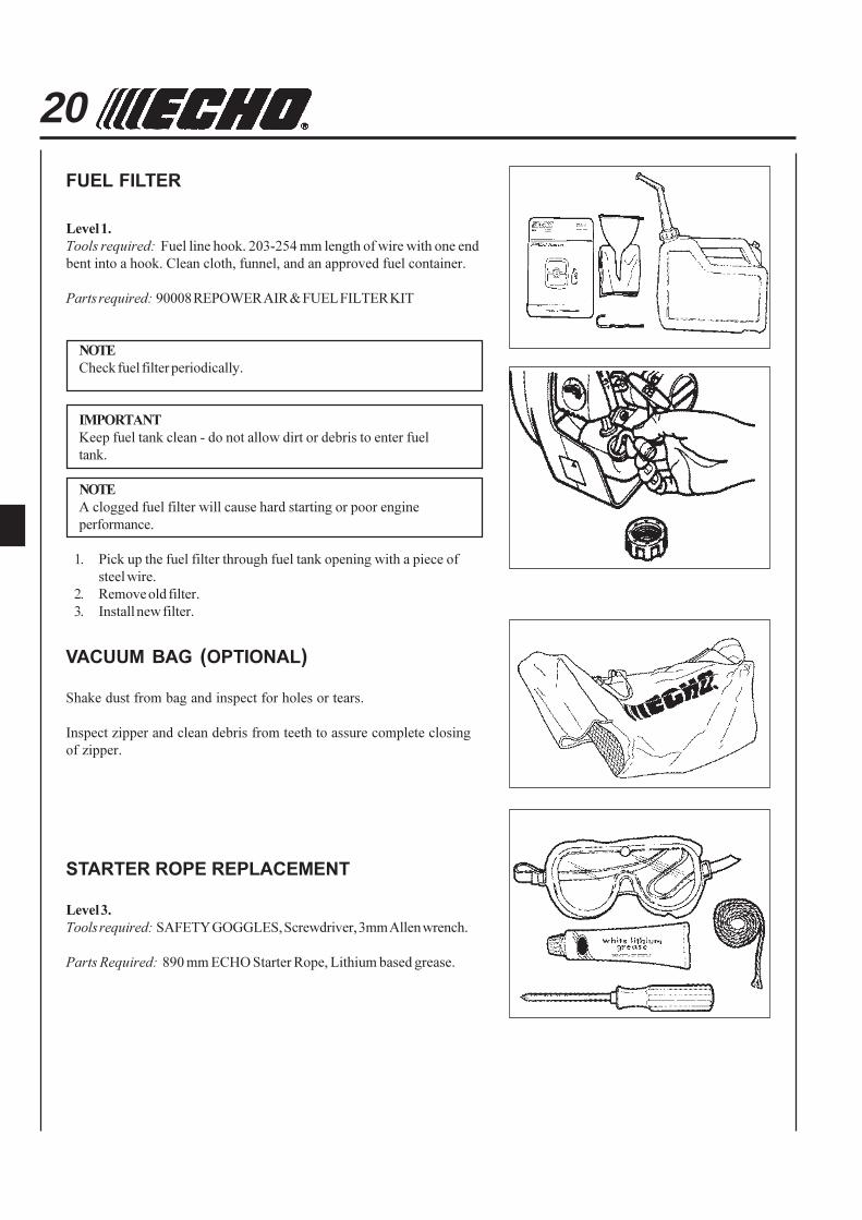
20FUEL FILTER
Level 1.
Tools required: Fuel line hook. 203-254 mm length of wire with one end
bent into a hook. Clean cloth, funnel, and an approved fuel container.
Parts required: 90008 REPOWER AIR & FUEL FILTER KIT
NOTE
Check fuel filter periodically.
IMPORTANT
Keep fuel tank clean - do not allow dirt or debris to enter fuel
tank.
NOTE
A clogged fuel filter will cause hard starting or poor engine
performance.
1. Pick up the fuel filter through fuel tank opening with a piece of
steel wire.
2. Remove old filter.
3. Install new filter.
VACUUM BAG (OPTIONAL)
Shake dust from bag and inspect for holes or tears.
Inspect zipper and clean debris from teeth to assure complete closing
of zipper.
STARTER ROPE REPLACEMENT
Level 3.
Tools required: SAFETY GOGGLES, Screwdriver, 3mm Allen wrench.
Parts Required: 890 mm ECHO Starter Rope, Lithium based grease.
21POWER BLOWER
OPERATOR'S MANUAL
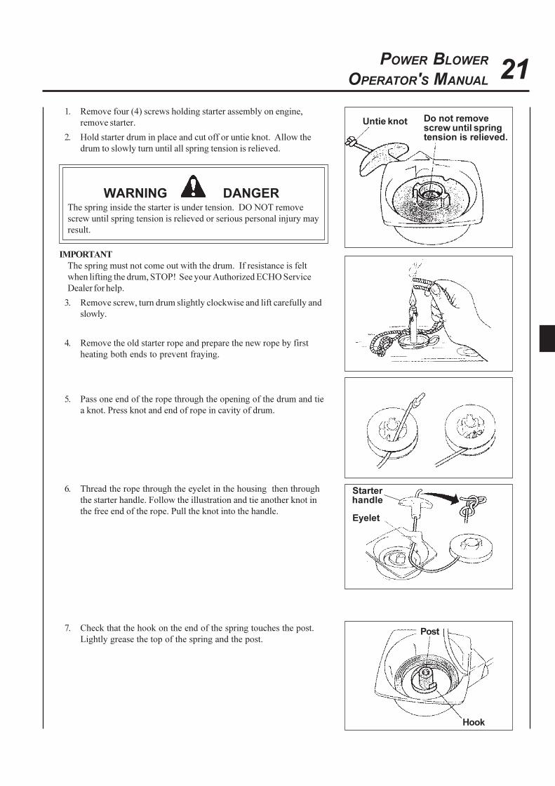
Untie knot
Starterhandle
Eyelet
1. Remove four (4) screws holding starter assembly on engine,
remove starter.
2. Hold starter drum in place and cut off or untie knot. Allow the
drum to slowly turn until all spring tension is relieved.
WARNING DANGERThe spring inside the starter is under tension. DO NOT remove
screw until spring tension is relieved or serious personal injury may
result.
IMPORTANT
The spring must not come out with the drum. If resistance is felt
when lifting the drum, STOP! See your Authorized ECHO Service
Dealer for help.
3. Remove screw, turn drum slightly clockwise and lift carefully and
slowly.
4. Remove the old starter rope and prepare the new rope by first
heating both ends to prevent fraying.
5. Pass one end of the rope through the opening of the drum and tie
a knot. Press knot and end of rope in cavity of drum.
6. Thread the rope through the eyelet in the housing then through
the starter handle. Follow the illustration and tie another knot in
the free end of the rope. Pull the knot into the handle.
Do not removescrew until springtension is relieved.
7. Check that the hook on the end of the spring touches the post.
Lightly grease the top of the spring and the post.
Hook
Post
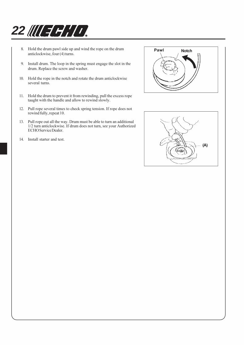
22Pawl Notch
(A)
8. Hold the drum pawl side up and wind the rope on the drum
anticlockwise, four (4) turns.
9. Install drum. The loop in the spring must engage the slot in the
drum. Replace the screw and washer.
10. Hold the rope in the notch and rotate the drum anticlockwiseseveral turns.
11. Hold the drum to prevent it from rewinding, pull the excess ropetaught with the handle and allow to rewind slowly.
12. Pull rope several times to check spring tension. If rope does notrewind fully, repeat 10.
13. Pull rope out all the way. Drum must be able to turn an additional1/2 turn anticlockwise. If drum does not turn, see your AuthorizedECHO Service Dealer.
14. Install starter and test.
23POWER BLOWER
OPERATOR'S MANUAL
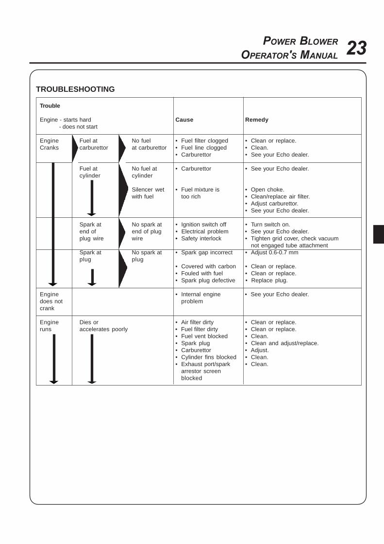
Trouble
Engine - starts hard Cause Remedy - does not start
Engine Fuel at No fuel • Fuel filter clogged • Clean or replace.Cranks carburettor at carburettor • Fuel line clogged • Clean.
• Carburettor • See your Echo dealer.
Fuel at No fuel at • Carburettor • See your Echo dealer.cylinder cylinder
Silencer wet • Fuel mixture is • Open choke.with fuel too rich • Clean/replace air filter.
• Adjust carburettor.• See your Echo dealer.
Spark at No spark at • Ignition switch off • Turn switch on.end of end of plug • Electrical problem • See your Echo dealer.plug wire wire • Safety interlock • Tighten grid cover, check vacuum
not engaged tube attachmentSpark at No spark at • Spark gap incorrect • Adjust 0.6-0.7 mmplug plug
• Covered with carbon • Clean or replace.• Fouled with fuel • Clean or replace.• Spark plug defective • Replace plug.
Engine • Internal engine • See your Echo dealer.does not problemcrank
Engine Dies or • Air filter dirty • Clean or replace.runs accelerates poorly • Fuel filter dirty • Clean or replace.
• Fuel vent blocked • Clean.• Spark plug • Clean and adjust/replace.• Carburettor • Adjust.• Cylinder fins blocked • Clean.• Exhaust port/spark • Clean.
arrestor screenblocked
TROUBLESHOOTING

24
STORAGE
Long Term Storage (Over 30 Days)
Do not store your unit for a prolonged period of time (30 days or longer)
without performing protective storage maintenance which includes the
following:
1. Store unit in a dry, dust free place, out of the reach of children.
WARNING DANGERDo not store in enclosure where fuel fumes may accumulate or
reach an open flame or spark or serious personal injury may
result.
2. Place the ignition switch in the "STOP" position.
3. Remove accumulation of grease, oil, dirt and debris from exterior of
unit.
4. Perform all periodic lubrication and services that are required.
5. Tighten all screws and nuts.
6. Drain the fuel tank completely and pull the recoil starter handle
several times to remove fuel from the carburettor.
7. Remove the spark plug and pour 1/4 oz. (1/2 tablespoon) of fresh,
clean ECHO 2-stroke engine oil into the cylinder through the spark
plug hole.
A. Place a clean cloth over the spark plug hole.
B. Pull the recoil starter handle 2-3 times to distribute the oil
inside the engine.
C. Observe the piston location through the spark plug hole.
Pull the recoil starter handle slowly until the piston reaches the
top of its travel and leave it there.
8. Install the spark plug (do not connect ignition cable).
9. Remove blower pipe assembly from unit.
25POWER BLOWER
OPERATOR'S MANUAL
GB
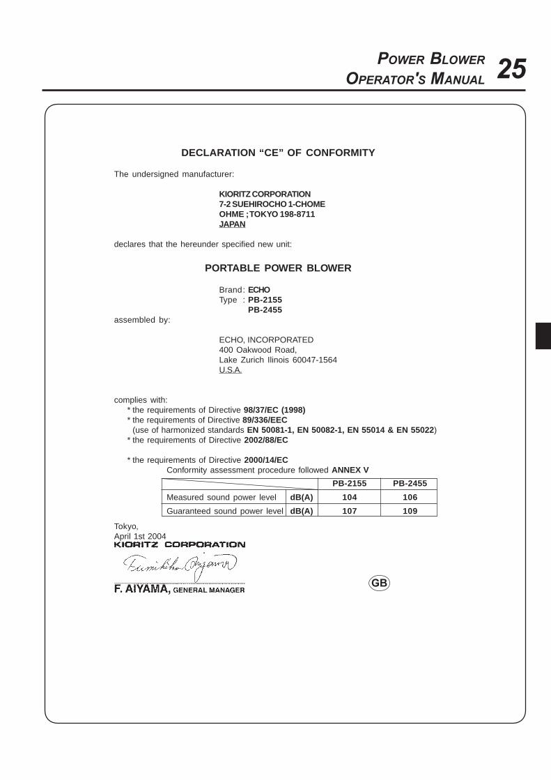
DECLARATION “CE” OF CONFORMITY
The undersigned manufacturer:
KIORITZ CORPORATION7-2 SUEHIROCHO 1-CHOMEOHME ; TOKYO 198-8711JAPAN
declares that the hereunder specified new unit:
PORTABLE POWER BLOWER
Brand: ECHOType : PB-2155
PB-2455assembled by:
ECHO, INCORPORATED400 Oakwood Road,Lake Zurich Ilinois 60047-1564U.S.A.
complies with:* the requirements of Directive 98/37/EC (1998)* the requirements of Directive 89/336/EEC
(use of harmonized standards EN 50081-1, EN 50082-1, EN 55014 & EN 55022)* the requirements of Directive 2002/88/EC
* the requirements of Directive 2000/14/ECConformity assessment procedure followed ANNEX V
PB-2155 PB-2455
Measured sound power level dB(A) 104 106
Guaranteed sound power level dB(A) 107 109
Tokyo,April 1st 2004

26

27POWER BLOWER
OPERATOR'S MANUAL

KIORITZ CORPORATION
7-2 SUEHIROCHO 1-CHOME, OHME, TOKYO, 198, JAPAN
PHONE: 81-428-326118 FAX: 81-428-32-6145
ECHO, INCORPORATED
400 Oakwood Road
Lake Zurich, IL 60047-1564
U.S.A.