operator´s manual rider 155 - hsqglobal´s manual rider 155 please read these instructions...
TRANSCRIPT

Operator´s manual
Rider 155
Please read these instructions carefully and make sureyou understand them before using the machine. English

Svenska – 31
Sve-5 225/232/235 Bruk 97-11-25, 08.4631

English – 1
Operator’s Manual forRider 155
CONTENTS
Safety rules for USA ........................................... 2Introduction ......................................................... 4
Driving and transport on public roads .............. 4Towing .............................................................. 4Intended use .................................................... 4Serial number ................................................... 5
Explanation of symbols ...................................... 6Placards ........................................................... 7
Safety instructions .............................................. 8General Use ..................................................... 8Driving on Slopes ........................................... 10Children .......................................................... 11Maintenance .................................................. 11Transport ........................................................ 12
Presentation ...................................................... 14Location of the controls .................................. 14Throttle/Choke lever ....................................... 15Speed limiter .................................................. 15Parking brake ................................................. 15Cutting unit ..................................................... 16Lift lever for cutting unit .................................. 16Lever for adjustment of cutting height ............ 17Seat ................................................................ 17Fuelling .......................................................... 17
Driving ................................................................ 18Before starting ................................................ 18Starting the engine ......................................... 18Driving the machine ....................................... 20Cutting tips ..................................................... 21Stopping the engine ....................................... 22Release lever ................................................. 22
Maintenance ...................................................... 23Maintenance schedule ................................... 23Removal of the machine hoods ..................... 24Checking and adjusting the steering wires .... 25
Adjusting the brake ........................................ 25Adjusting the throttle wire ............................... 26Service of air filter .......................................... 27Battery ............................................................ 28Ignition System .............................................. 28Inspection of the safety system ...................... 29Main fuse ....................................................... 30Checking the tyre pressure ............................ 30Checking the engine’s cooling air intake ........ 30Fitting the cutting unit ..................................... 31Removing the cutting unit .............................. 32Checking and adjustment of cutting unit’sground pressure ............................................. 33Checking the parallelism of the cutting unit ... 34Adjusting the parallelism of the cutting unit .... 34Replacing the cutting unit belt ........................ 35Service position for cutting unit ...................... 36Checking the blades ...................................... 39Replacing the break-pin ................................. 40Removal of BioClip plug ................................. 40
Lubrication ......................................................... 41Checking the engine’s oil level ....................... 41Changing the oil ............................................. 41Change of oil filter .......................................... 42Checking the transmission’s oil level ............. 42Lubricating the belt adjuster ........................... 42General lubrication ......................................... 42
Trouble shooting schedule .............................. 43Storage ............................................................... 44
Winter storage ................................................ 44Cover ............................................................. 44Service ........................................................... 44
Technical data ................................................... 45Service journal .................................................. 46
IMPORTANT INFORMATION
Read carefully through the Operator’s manual so that you know how to use and maintain theRider before you use it.
For service measures other than those described in this manual, please contact an authoriseddealer that provides parts and service.

2 – English
These instructions are for your safety. Read them carefully.
Safe operation practices for ride-on mowers
IMPORTANT!This cutting machine is capable of amputating hands and feet and throwing objects. Failure toobserve the following safety instructions could result in serious injury or death.
1. Safety rules for USA
I. General operation
1. Read, understand and follow all instructions inthe manual and on the machine beforestarting.
2. Only allow responsible adults, who are familiarwith the instructions, to operate the machine.
3. Clear the area of objects such as rocks, toys,wire, etc., which could be picked up andthrown by the blade.
4. Be sure the area is clear of other peoplebefore mowing. Stop the machine if anyoneenters the area.
5. Never carry passengers.6. Do not mow in reverse unless absolutely
necessary. Always look down and behindbefore and while backing.
7. Be aware of the mower discharge directionand do not point it at anyone. Do not operatethe mower without either the entire grasscatcher or the guard in place.
8. Slow down before turning.9. Never leave a running machine unattended.
Always turn off blades, set parking brake, stopengine and remove keys before dismounting.
10. Turn off blades when not mowing.11. Stop engine before removing grass catcher or
unclogging chute.12. Mow only in daylight or good artificial light.13. Do not operate the machine while under the
influence of alcohol or drugs.
14. Watch for traffic when operating near orcrossing roadways.
15. Use extra care when loading or unloading themachine into a trailer or truck.
II. Slope operationSlopes are a major factor related to loss-of-controland tip-over accidents, which can result in severeinjury or death. All slopes require extra caution. Ifyou cannot back up the slope or if you feel uneasyon it, do not mow it.
DOMow up and down slopes, not across.Remove obstacles such as rocks, tree limbs,etc.Watch for holes, ruts or bumps. Uneventerrain could overturn the machine. Tall grasscan hide obstacles.
Use slow speed. Choose a low gear so thatyou will not have to stop or shift while on theslope.Follow the manufacturer’s recommendationsfor wheel weights or counterweights to improvestability.Use extra care with grass catchers or otherattachments. These can change the stability ofthe machine.Keep all movement on the slopes slow andgradual. Do not make sudden changes inspeed or direction.Avoid starting or stopping on a slope. If tireslose traction, disengage the blades andproceed slowly straight down the slope.
DO NOTDo not turn on slopes unless necessary andthen, turn slowly and gradually downhill, ifpossible.Do not mow near drop-offs, ditches orembandments. The mower could suddenly turnover if a wheel is over the edge of a cliff orditch, or if an edge caves in.Do not mow on wet grass. Reduced tractioncould cause sliding.Do not try to stabilize the machine by puttingyour foot on the ground.Do not use grass catcher on steep slopes.
III. Children
Tragic accidents can occur if the operator is notalert to the presence of children. Children are oftenattracted to the machine and the mowing activity.Never assume that children will remain where youlast saw them.1. Keep children out of the mowing area and
under the watchful care of another responsibleadult.
2. Be alert and turn machine off if children enterthe area.
3. Before and when backing, look behind anddown for small children.
4. Never carry children. They may fall off and beseriously injured or interfere with safe machineoperation.
5. Never allow children to operate the machine.
6. Use extra care when approaching blindcorners, shrubs, trees or other objects that mayobscure vision.

English – 3
IV. Service
1. Use extra care in handling gasoline and otherfuels. They are flammable and vapours areexplosive.
a) Use only an approved container.
b) Never remove gas cap or add fuel with theengine running. Allow engine to cool beforerefuelling. Do not smoke.
c) Never refuel the machine indoors.
d) Never store the machine or fuel containerinside where there is an open flame, such asin a water heater.
2. Never run a machine inside a closed area.
3. Keep nuts and bolts, especially bladeattachment bolts, tight and keep equipment ingood condition.
4. Never tamper with safety devices. Check theirproper operation regularly.
5. Keep machine free of grass, leaves or otherdebris build-up. Clean up oil or fuel spillage.Allow machine to cool before storing.
6. Stop and inspect the equipment if you strike anobject. Repair, if necessary, before restarting.
7. Never make adjustments or repairs with theengine running.
8. Grass catcher components are subject to wear,damage and deterioration, which could exposemoving parts or allow objects to be thrown.Frequently check components and replace withmanufacturer’s recommended parts, whennecessary.
9. Mower blades are sharp and can cut. Wrap theblade(s) or wear gloves and use extra cautionwhen servicing them.
10. Check brake operation frequently. Adjust andservice as required.
Danger, keep hands and feet away
Travel and transport on public roadsCheck the relevant road traffic regulations beforedriving the machine on a public road. If transportingthe machine on another vehicle always useapproved securing devices and make sure that themachine is securely held.
TowingIf your machine has a hydrostatic transmission youshould only tow it very short distances at low speedif absolutely necessary, otherwise the transmissionmay be damaged.
Intended useThis machine is designed solely for cutting grasson conventional lawns and other cleared andleveled ground without obstacles, as rocks, stumpsetc., and, in conjunction with accessories suppliedby the manufacturer even for other special tasksfor which instructions are delivered with theaccessory. Use in any other way is considered ascontrary to the intended use. Compliance with andstrict adherence to the conditions of operation,service and repair as specified by the manufactureralso constitute essential elements of the intendeduse.This machine should be operated, serviced andrepaired only by persons who are familiar with itsparticular characteristics and who are acquaintedwith the relevant safety procedures.Accident prevention regulations, all other generallyrecognised regulations on safety and occupationalmedicine, and all road traffic regulations must beobserved at all times.Any arbitrary modifications carried out to thismachine may relieve the manufacturer of liability forany resulting damage or injury.
Safe operation practices for Ride-On MowersBefore starting cutting operations, train differentdriving operations on an open ground withoutpeople nearby until you feel familiar with handlingthe equipment. This is particularly important if youhave no or little prior experience of driving avehicle.Data indicates that operators, age 60 years andabove, are involved in a large percentage of ridingmower-related injuries. These operators shouldevaluate their ability to operate the riding mowersafely in order to protect themselves and othersfrom serious injury.Never carry children, even with the blades off. Theymay fall off and be seriously injured or interfere withsafe machine operation.
1. Safety rules for USA

4 – English
INTRODUCTION
Dear customer
Thank you for choosing a Husqvarna Rider. Husqvarna Riders are built to a unique design with afrontmounted cutting unit and a patented rear-wheel steering system. Riders are designed for maximumefficiency even in small or confined areas. Collected controls and a hydrostatic transmission controlled bypedals also contribute to the machine’s performance.
We hope you will find this operator’s manual very useful. By following its instructions (on operation, service,maintenance, etc.) you will significantly extend the life of the machine and even its second-hand value.
When you sell your Rider, make sure you pass on the operator’s manual to the new owner.
Travel and transport on public roads
Check the relevant road traffic regulations before driving the machine on a public road. If transporting themachine on another vehicle always use approved securing devices and make sure that the machine issecurely held.
Towing
Your machine is equipped with a hydrostatic transmission and, if necessary, you should only tow the machineover short distances and at a low speed, otherwise there is a risk of damaging the transmission.
Intended use
This machine is designed solely for cutting grass on conventional lawns and other cleared and leveledground without obstacles, as rocks, stumps etc., and, in conjunction with accessories supplied by themanufacturer even for other special tasks for which instructions are delivered with the accessory. Use in anyother way is considered as contrary to the intended use. Compliance with and strict adherence to theconditions of operation, service and repair as specified by the manufacturer also constitute essentialelements of the intended use.
This machine should be operated, serviced and repaired only by persons who are familiar with its particularcharacteristics and who are acquainted with the relevant safety procedures.
Accident prevention regulations, all other generally recognised regulations on safety and occupationalmedicine, and all road traffic regulations must be observed at all times.
Any arbitrary modifications carried out to this machine may relieve the manufacturer of liability for anyresulting damage or injury

English – 5
INTRODUCTION
Good service
Husqvarna products are sold all over the world and only through servicing dealers. This is to ensure that you,the customer, get the best support and service.
When you need spare parts or advice on service issues, warranty terms, etc., contact:
This Operator’s Manual belongs tomachine with serial number:
Serial number
The serial number can be found on the printed plate attached to the front, left-hand side under the seat.Stated on the plate, from the top are:
• The machines type designation.
• The manufacturer’s type number.
• The machine’s serial number.
State the type designation and serial number when ordering spare parts.
The engine identfication numbers appear on a decal affixed to the engine shrouding. The text states:
• Model no.
• Spec no.
• Serial no.
Please state these when ordering spare parts. Include letter suffixes, if there are any.
The transmission’s serial number is stated on the barcode decal located on the front of the housing on theleft-hand drive axle:
• Type designation is stated above the barcode and starts with the letter “K”.
• The serial number is stated above the barcode and has the prefix “s/n”.
• The manufacturer’s type number is stated under the barcode and has the prefix “p/n”.
State the type designation and serial number when ordering spare parts.
Engine Transmission

6 – English
These symbols are on the machine and in the operator’s manual.Study them carefully so that you know what they mean.
Read the operator’s manual
Reverse Neutral Fast Slow Engine off Battery Choke Fuel
Oil level Cutting height Backwards Forwards Ignition
Hydrostatic free wheel Use hearing protection Parking brake Brake Warning
Never use the machine if persons, especiallychildren, or animals, are in the vicinity.
STARTING INSTRUCTION• READ OPERATOR´S MANUAL.• CHECK ENGINE OIL LEVEL.• ENGAGE PARKING BRAKE AND LIFT CUTTING DECK IN TRANSPORT POSITION.• IF ENGINE IS COLD USE CHOKE.• START THE ENGINE.• RELEASE PARKING BRAKE BEFORE DRIVING.
INSTRUCTIONS DE DEMARRAGE• LIRE LE GUIDE DE CONDUITE.• VÉRIFIEZ LE NIVEAU D´HUILE MOTEUR.• SERREZ LE FREIN DE PARKING ET METTRE LE CARTER DE COUPE EN POSITION HAUT.• SI LE MOTEUR EST FROID, UTILISEZ LE STARTER.• ACTIONNEZ LE DÉMARREUR.• DESSERREZ LE FREIN DE PARKING
Drive very slowlywithout the cutting unit.
NR
EXPLANATION OF SYMBOLS
Speed limiter pedal forwards
Neutral
Speed limiter pedal reverse
Switch off the engine and take offthe ignition cable before repairs ormaintenance
Never carry passengers on themachine or equipment.
Warning!Risk that the
machine can tip overNever drive across a
slope
Keep hands and feet away frommoving parts.

English – 7
EXPLANATION OF SYMBOLS
8009-442
Placards
8 – English
8010-047
6003-002
8010-052
Safety instructionsThese instructions are for your safety. Read them carefully.
General use
• Read all the instructions in this operator’smanual and on the machine before you start it.Ensure you understand them and then observethem.
• Learn how to use the machine and its controlssafely and learn to how to stop quickly. Alsolearn to recognize the safety decals.
• Only allow the machine to be used by adultswho are familiar with its use.
• Make sure nobody else is in the vicinity of themachine when you start the engine, engage thedrive or drive off.
• Make sure animals and people maintain a safedistance from the machine.
• Stop the machine if any one enters the workingarea.
• Clear the area of objects such as stones, toys,wires, etc. that may become caught in the bladesand be thrown out.
• Look out for the ejector and do not direct ittowards anyone.
• Stop the engine and prevent the engine frombeing started until you have cleaned the cuttingunit or outlet channel.
• Remember the operator is responsible fordanger or accidents.
• Never carry passengers. The machine is onlyintended to be used by one person.
• Always look downwards and backwards beforeand while reversing. Keep watch for both largeand small obstacles.
• Slow before cornering.
• Switch off the blades when you are not mowing.
SAFETY INSTRUCTIONS
WARNING!This machine can sever hands and feet as well as throw objects.Failure to observe the safety instructions can result in serious injuries.
WARNING!The inserted symbol means that important safety instructions need to be observed. Itapplies to your safety.
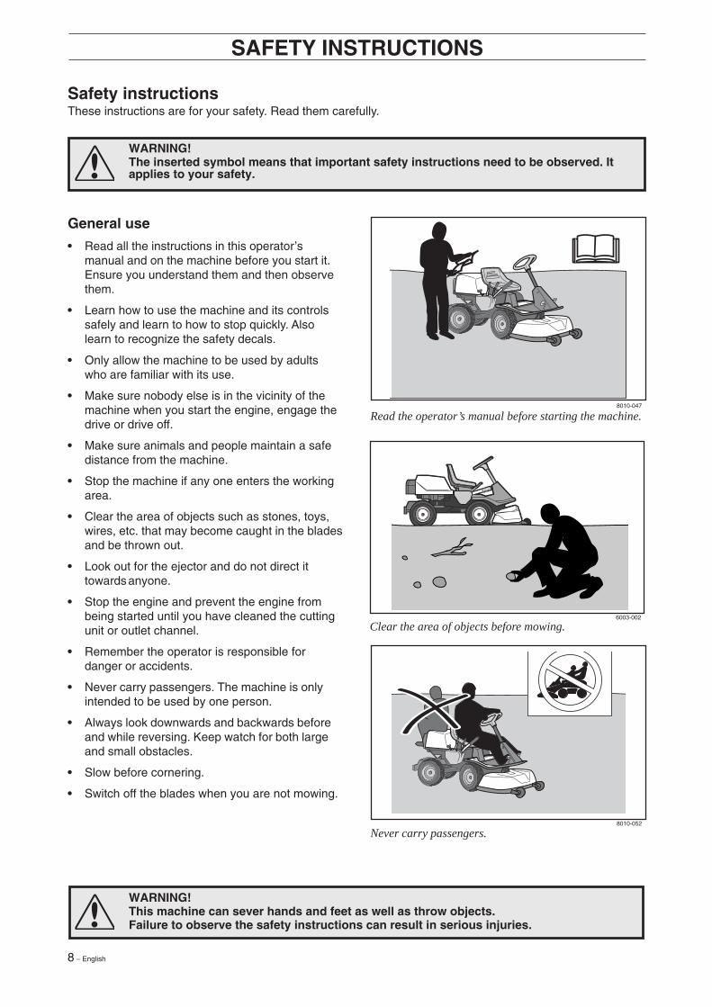
Never carry passengers.
Read the operator’s manual before starting the machine.
Clear the area of objects before mowing.

English – 9
6003-006
8011-292
• Take care when rounding a fixed object, so thatthe blades do not hit it. Never run the machineover foreign objects.
• Only use the machine in daylight or in otherwell-lit conditions. Keep the machine at a safedistance from holes or other irregularities in theground. Pay attention to other possible risks.
• Never use the machine if you are tired, if youhave consumed alcohol, or if you are takingother drugs or medication that can affect yourvision, judgment or co-ordination.
• Keep an eye on the traffic when working close toa road or when crossing it.
• Never leave the machine unsupervised with theengine running. Always stop the blades, applythe parking brake, stop the engine and removethe keys before leaving the machine.
• Never allow children or other persons nottrained in the use of the machine to use orservice it. Local laws may regulate the age ofthe user.
SAFETY INSTRUCTIONS
WARNING!Engine exhaust, some of itsconstituents and certain vehiclecomponents contain or emitchemicals considered to causecancer, birth defects or otherreproductive impairment. Theengine emits carbon monoxide,which is a colourless, poisonousgas. Do not use the machine inenclosed spaces.
WARNING!You must use approved personal protective equipment whenever you use themachine. Personal protective equipment cannot eliminate the risk of injury but it willreduce the degree of injury if an accident does happen. Ask your dealer for help inchoosing the right equipment.
• Make sure that you have first aid equipmentclose at hand when using the machine.
• Never use the machine when barefoot. Alwayswear protective shoes or protective boots,preferably with steel toes.
• Wear approved protective glasses or full-facevisor during assembly and when operating.
• Never wear loose fitting clothes that can catch inmoving parts.
• Use ear protectors to eliminate the risk forimpairment of hearing.
Keep children away from the area to be mowed.
Personal protective equipment.

10 – English
8010-054
6003-004
Be especially careful when driving on slopes.
Mow upwards and downwards on slopes, not sideways.
Driving on slopes
Driving on slopes is one of the operations wherethe risk of the driver losing control of the machineor of it overturning is the greatest; this can result inserious injury or death. All slopes demand extracare. If you cannot reverse up a slope or if you feelunsure, do not mow it.
Proceed as follows:
• Remove obstacles such as stones, branches,etc.
• Mow upwards and downwards, not sideways.
• Do not use the machine on ground that slopesmore than 15°.
• Avoid starting or stopping on a slope. If the tyresstart to slip, stop the blades and drive slowlydown the slope.
• Always drive smoothly and slowly on slopes.
• Do not make any sudden changes in speed ordirection.
• Avoid unnecessary turns on slopes, ifnecessary, turn slowly and gradually downwardsif possible.
• Watch out for and avoid driving over furrows,holes and bumps. It is easier for the machine tooverturn on uneven ground. Tall grass can hideobstacles.
• Drive slowly. Do not turn the wheel sharply. Themachine engine-brakes better in low gear.
• Take extra care if any attachments are fitted thatcan change the stability of the machine.
• Do not mow too close to edges, ditches orbanks. The machine can suddenly overturn ifone wheel comes over the edge of a steepslope or a ditch, or if an edge gives way.
• Do not mow wet grass. It is slippery, and tyrescan lose their grip so that the machine skids.
• Do not try to stabilize the machine by puttingyour foot on the ground.
• When cleaning the chassis the machine mustnever be driven close to an edge or ditch.
• Follow the manufacturer’s recommendationsregarding wheel weights or counterbalanceweights to increase stability.
SAFETY INSTRUCTIONS

English – 11
8010-057
8010-058
Children
• Serious accidents may occur if you fail to be onyour guard for children in the vicinity of themachine. Children are often attracted to themachine and mowing. Never assume thatchildren will remain where you last saw them.
• Keep children away from the area to be mowedand under close supervision by another adult.
• Keep an eye out and shut off the machine ifchildren enter the work area.
• Before and during reversing procedures, lookbehind you and down for small children.
• Never allow children to ride along. They can falloff and seriously injure themselves or be in theway for safe manoeuvring of the machine.
• Never allow children to operate the machine.
• Be particularly careful near corners, bushes,trees or other objects that block your view.
SAFETY INSTRUCTIONS
Never allow children to operate the machine.
Never fill the fuel tank indoors.
Maintenance
• Stop the engine. Prevent starting by removingthe ignition cable from the spark plug or removethe ignition key before making any adjustmentsor carrying out maintenance.
• Never fill the fuel tank indoors.
• Petrol and petrol fumes are poisonous andextremely flammable. Be especially careful whenhandling petrol, as carelessness can result inpersonal injury or fire.
• Only store fuel in containers approved for thepurpose.
• Never remove the fuel cap and fill the petroltank while the engine is running.
• Allow the engine to cool before refuelling. Donot smoke. Do not fill petrol in the vicinity ofsparks or naked flames.
• Electrical shock can cause injury. Do not touchwires while engine is running or cranked around.Do not test ignition system using your finger.
• Pay attention to the risk of environmentalinfluence when handling oil, oil filter, fuel andbattery. Observe the local waste regulations.
12 – English
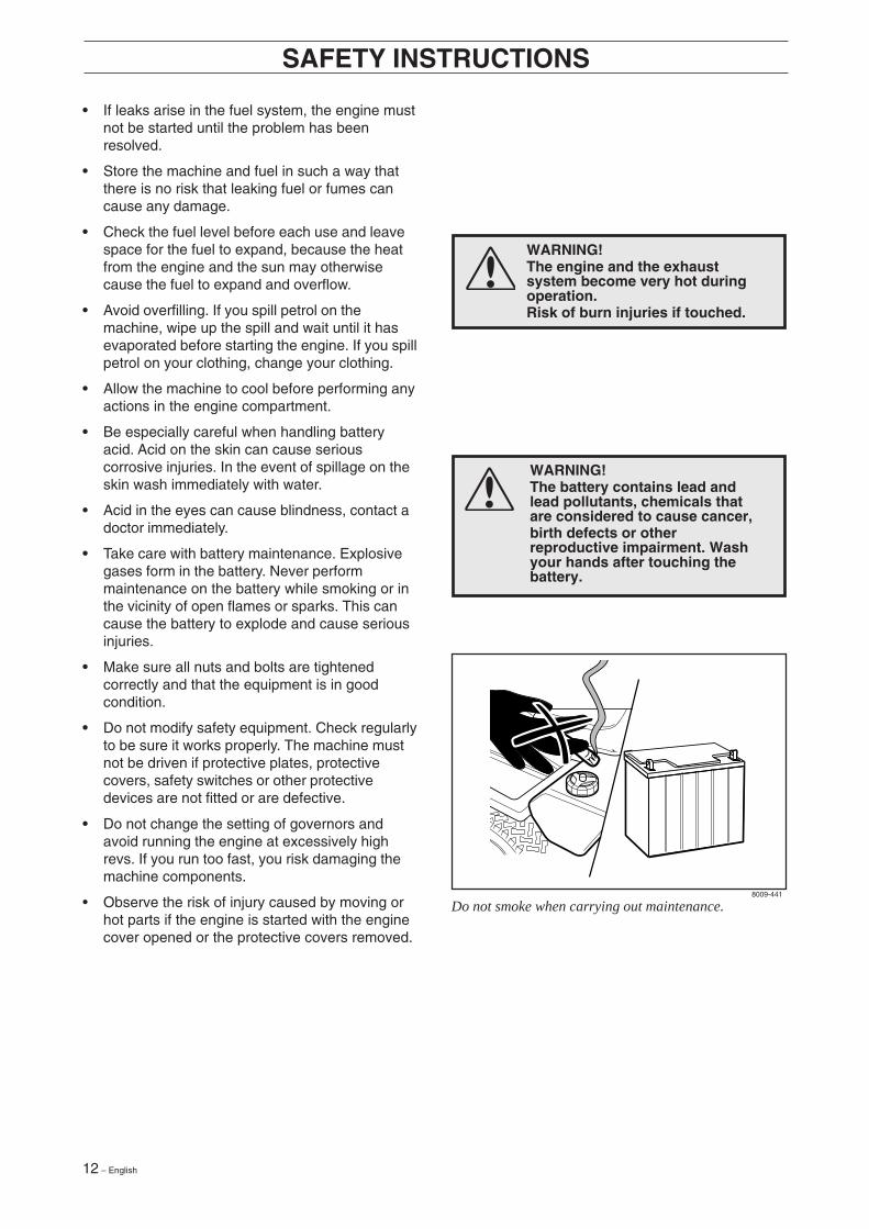
WARNING!The engine and the exhaustsystem become very hot duringoperation.Risk of burn injuries if touched.
WARNING!The battery contains lead andlead pollutants, chemicals thatare considered to cause cancer,birth defects or otherreproductive impairment. Washyour hands after touching thebattery.
8009-441
• If leaks arise in the fuel system, the engine mustnot be started until the problem has beenresolved.
• Store the machine and fuel in such a way thatthere is no risk that leaking fuel or fumes cancause any damage.
• Check the fuel level before each use and leavespace for the fuel to expand, because the heatfrom the engine and the sun may otherwisecause the fuel to expand and overflow.
• Avoid overfilling. If you spill petrol on themachine, wipe up the spill and wait until it hasevaporated before starting the engine. If you spillpetrol on your clothing, change your clothing.
• Allow the machine to cool before performing anyactions in the engine compartment.
• Be especially careful when handling batteryacid. Acid on the skin can cause seriouscorrosive injuries. In the event of spillage on theskin wash immediately with water.
• Acid in the eyes can cause blindness, contact adoctor immediately.
• Take care with battery maintenance. Explosivegases form in the battery. Never performmaintenance on the battery while smoking or inthe vicinity of open flames or sparks. This cancause the battery to explode and cause seriousinjuries.
• Make sure all nuts and bolts are tightenedcorrectly and that the equipment is in goodcondition.
• Do not modify safety equipment. Check regularlyto be sure it works properly. The machine mustnot be driven if protective plates, protectivecovers, safety switches or other protectivedevices are not fitted or are defective.
• Do not change the setting of governors andavoid running the engine at excessively highrevs. If you run too fast, you risk damaging themachine components.
• Observe the risk of injury caused by moving orhot parts if the engine is started with the enginecover opened or the protective covers removed.
SAFETY INSTRUCTIONS
Do not smoke when carrying out maintenance.

English – 13
8009-467
8010-061
SAFETY INSTRUCTIONS
• Never use the machine indoors or in spaceslacking proper ventilation. Exhaust fumescontain carbon monoxide, an odourless,poisonous and highly dangerous gas.
• Stop and inspect the equipment if you run overor into anything. If necessary, make repairsbefore starting.
• Never make adjustments with the enginerunning.
• The machine is tested and approved only withthe equipment originally provided orrecommended by the manufacturer.
• The blades are sharp and can cause cuts. Wrapthe blades or wear protective gloves whenhandling them.
• Check regularly that the parking brake works.Adjust and maintain as required.
• The mulching function should only be usedwhere better quality mowing is required and inknown areas.
• Reduce the risk of fire by removing grass, leavesand other debris that may have fastened on themachine. Allow the machine to cool beforeputting it in storage.
Transport
• The machine is heavy and can cause seriouscrush injuries. Be especially careful when it isloaded in or out of a car or on and off of a trailer.
• Use an approved trailer to transport themachine. Activate the parking brake and securethe machine using approved fasteners, such astension belts, chains or ropes when transporting.
• Check and observe local road traffic regulationsbefore transporting or driving the machine onroads.
IMPORTANT INFORMATION
The parking brake is not sufficient to lockthe machine during transport. Ensure yousecure the machine firmly to thetransporting vehicle. Reverse the machineon to the transporting vehicle to prevent itfrom overturning.
Regularly clean grass, leaves and other debris from themachine.
Never run the machine in an enclosed area.

14 – English
Presentation
Congratulations on your choice of a top qualityproduct which you will enjoy for many years.
These instructions describe the Rider 155. Thisrider mower is equipped with a 15.5 horsepowerKohler engine.
PRESENTATION
Location of the controls
1. Ignition lock
2. Throttle/Choke lever
3. Adjustment of cutting height
4. Lifting lever, cutting unit
5. Speed limiter for reversing
6. Speed limiter for driving forwards
7. Parking brake
8. Lock button for parking brake
9. Knobs for adjusting seat
10. Fuel tank cap
11. Main lock (under seat)
12. Lever for disengagement of drive
The power transmission from the engine is handledby a hydrostatic gearbox, which allows variablevariation of the speed by using the pedals.
There is one pedal for driving forwards and onepedal for reversing.
6017-213
8009-114

English – 15
PRESENTATION
Throttle and Choke lever
The engine speed is adjusted with the throttlecontrol, and thereby also the rotation speed of theblades.
The control is also used to activate the chokefunction. When the choke is used the enginereceives a richer mixture of fuel and air, whichsimplifies cold start.
1
2
2 1
WARNING!Make sure that branches do notobstruct the pedals when mowingunder bushes, otherwise you maylose control.
Parking brake
The parking brake is applied as follows:
1. Press down the brake pedal.
2. Press in the lock button on the steering column.
3. Release up the brake pedal while holding thebutton pressed.
The lock on the parking brake automaticallydisconnects when the brake pedal is pressed.
Speed limiter
The speed of the machine is steplessly regulatedwith two pedals. Pedal (1) is used to drive forwardsand pedal (2) for reversing.
6004-004H
6017-214A
6017-011

16 – English
PRESENTATION
Cutting unit
The Rider 155 is equipped with cutting unit.
• Combi - 1030 mm/41"
The combi deck functions as a mulching deck whena BioClip plug is mounted. Otherwise, the deck willfunction as a rear ejection deck.
Lifting of the cutting unit (transport position)
Lowering of the cutting unit (cutting position)
Lift lever for cutting unit
The lift lever is used to set the cutting unit intransport or cutting position.
If the lever is pulled back the unit will lift up and theblades will automatically stop rotating (transportposition).
If the lock button is pressed and the lever is movedforward the unit will be lowered and the blades willautomatically start rotating (cutting position).
The lever can also be used to temporarily regulatethe cutting height, e.g. for a small mound in thelawn.
6017-214
6004-011H
6004-012H

English – 17
PRESENTATION
Fuelling
The engine should be run on 87 octane (or higher)unleaded petrol/gasoline (no added oil).
Gasohol or MTBE mix, see “Technical Data”.
No other fuel is approved by Kohler Engines.
Do not fill the tank completely, leave an expansionarea of at least 2.5 cm (1").
Seat
The seat has a jointed attachment on the frontedge and can be tipped forward.
The seat can also be adjusted lengthways.
Release the knobs under the seat and adjust itforwards or backwards to the required position.
Lock the setting with the knobs.
Lever for adjustment of cutting height
With this lever the cutting height can be adjusted to9 different positions.
Combi 103 unit, 45-95 mm(1 3/4" - 3 3/4")
WARNING!Petrol/gasoline is highlyinflammable. Observe care andfill up with fuel outdoors (seesafety instructions).
6004-013H
6004-014H
6004-015

18 – English
Before starting
• Read the safety instructions and information onthe location and function of the controls beforestarting.
• Conduct daily maintenance before starting (see“Maintenance Schedule”).
DRIVING
Cold engine:3. Push the throttle control to position 3 (choke
position). In this position the engine receives aricher mixture so that the engine starts moreeasily.
1
2
12
3
6007-001H
6017-011
6007-004H
8009-431
IMPORTANT INFORMATION
The air intake grille in the engine coverbehind the driver’s seat must not beblocked by, for example, clothing, leaves,grass or dirt.
Impaired cooling of the engine. Risk ofmajor engine damage.
Starting the engine
1. Lift up the cutting unit by pulling the leverbackwards to locked position (transportposition).
2. Apply the parking brake. This is done as follows:
• Press down the brake pedal (1).
• Press in the lock button on the steeringcolumn (2).
• Release the brake pedal while the button isheld pressed.
The parking brake lock disconnectsautomatically when the brake pedal is presseddown.

English – 19
DRIVING
Warm engine:4. Set the throttle control midway between position
1 and 2.
WARNING!Never run the engine indoors, inenclosed or poorly ventilatedareas. The exhaust fumes containtoxic carbon monoxide.
6. When the engine has started release the ignitionkey to neutral position.
Push the throttle control to the required speed.For cutting 3/4 to full throttle.
IMPORTANT INFORMATION
Do not run the starter for more than about10 seconds at a time. If the engine doesnot start, wait about 60 seconds beforetrying again.
5. Turn the ignition key to start position.
12
3
STOP START
STOP START
6007-005H
6007-006
6007-007

20 – English
DRIVING
Driving the machine
1. Release the parking brake by pressing down thebrake pedal.
3. Select the required cutting height (1-9) with thecutting height lever.
To obtain a uniform cutting height it is importantthat the tyre pressures are equal on both frontwheels 60 kPa/8.5 PSI.
2 12. Carefully press down one of the pedals until the
correct speed is reached.
To drive forwards: press down pedal (1).To reverse: press down pedal (2).
6017-012
6017-214A
6007-008H
English – 21
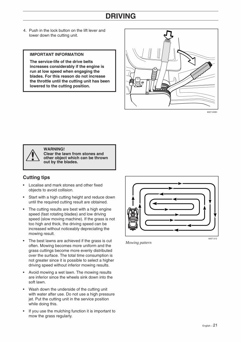
Mowing pattern
DRIVING
4. Push in the lock button on the lift lever andlower down the cutting unit.
WARNING!Clear the lawn from stones andother object which can be thrownout by the blades.
Cutting tips
• Localise and mark stones and other fixedobjects to avoid collision.
• Start with a high cutting height and reduce downuntil the required cutting result are obtained.
• The cutting results are best with a high enginespeed (fast rotating blades) and low drivingspeed (slow moving machine). If the grass is nottoo high and thick, the driving speed can beincreased without noticeably depreciating themowing result.
• The best lawns are achieved if the grass is cutoften. Mowing becomes more uniform and thegrass cuttings become more evenly distributedover the surface. The total time consumption isnot greater since it is possible to select a higherdriving speed without inferior mowing results.
• Avoid mowing a wet lawn. The mowing resultsare inferior since the wheels sink down into thesoft lawn.
• Wash down the underside of the cutting unitwith water after use. Do not use a high pressurejet. Put the cutting unit in the service positionwhile doing this.
• If you use the mulching function it is important tomow the grass regularly.
IMPORTANT INFORMATION
The service-life of the drive beltsincreases considerably if the engine isrun at low speed when engaging theblades. For this reason do not increasethe throttle until the cutting unit has beenlowered to the cutting position.
6007-212
6007-009H

22 – English
DRIVING
Stopping the engine
Preferably allow the engine to idle for a minute(always min 15 sec) to obtain normal workingtemperature before stopping it, if it has beenworking hard.
1. Lift up the cutting unit by pulling the lever backto the end position.
STOP START
MAX 15
WARNING!Never drive the machine onground with a slope of more than15°. Mow slopes upwards anddownwards, never across. Avoidsudden changes in direction.
Release lever
The release control must be pulled out in order forthe Rider to be moved when the engine is shutoff.
2. Pull back the throttle control and turn the ignitionkey to the STOP position.
3. When the Rider is at a standstill, press down theparking brake and push in the locking button.
6017-002
6007-014H
6007-015
6007-217H
English – 23
50 100
MAINTENANCE
25
WARNING!
No service procedures must be conducted on the engine or cutting unit unless:
• The engine is switched off.
• The ignition key is removed.
• The ignition cable is removed from the plug.
• The parking brake is applied.
• The cutting unit is disengaged.
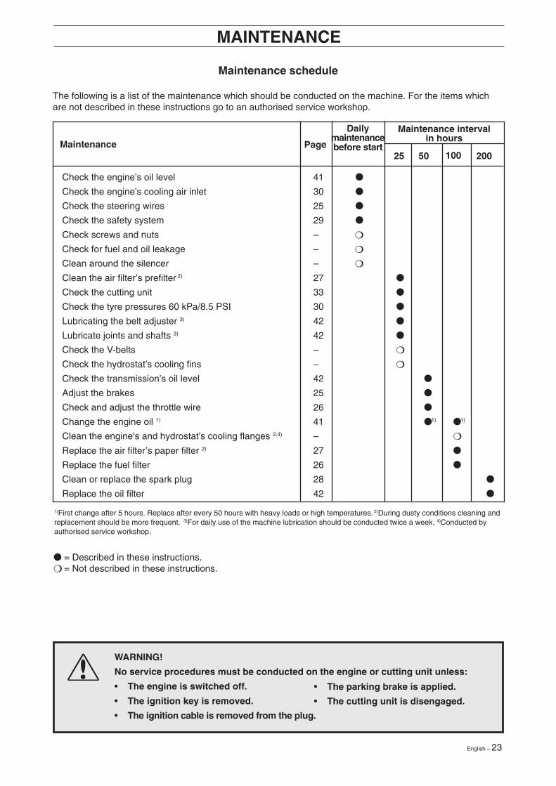
Maintenance schedule
The following is a list of the maintenance which should be conducted on the machine. For the items whichare not described in these instructions go to an authorised service workshop.
Dailymaintenancebefore start
● = Described in these instructions.❍ = Not described in these instructions.
Maintenance Page
Maintenance intervalin hours
1)First change after 5 hours. Replace after every 50 hours with heavy loads or high temperatures. 2)During dusty conditions cleaning andreplacement should be more frequent. 3)For daily use of the machine lubrication should be conducted twice a week. 4)Conducted byauthorised service workshop.
Check the engine’s oil level 41 ●
Check the engine’s cooling air inlet 30 ●
Check the steering wires 25 ●
Check the safety system 29 ●
Check screws and nuts – ❍
Check for fuel and oil leakage – ❍
Clean around the silencer – ❍
Clean the air filter’s prefilter 2) 27 ●
Check the cutting unit 33 ●
Check the tyre pressures 60 kPa/8.5 PSI 30 ●
Lubricating the belt adjuster 3) 42 ●
Lubricate joints and shafts 3) 42 ●
Check the V-belts – ❍
Check the hydrostat’s cooling fins – ❍
Check the transmission’s oil level 42 ●
Adjust the brakes 25 ●
Check and adjust the throttle wire 26 ●
Change the engine oil 1) 41 ● 1) ● 1)
Clean the engine’s and hydrostat’s cooling flanges 2,4) – ❍
Replace the air filter’s paper filter 2) 27 ●
Replace the fuel filter 26 ●
Clean or replace the spark plug 28 ●
Replace the oil filter 42 ●
200

24 – English
Removal of the machine hoods
Engine hoodThe engine is accessible for servicing when theengine hood is lifted up.
Tilt the seat forward, release the rubber strap underthe seat, and tilt the hood backwards.
MAINTENANCE
Left-hand fenderRelease the screws in the fender (2) and lift off thefender.
Right-hand fenderRemove the knob (1), the screws (2 and 3) and liftoff the fender.
Front hoodRelease the clip on the front hood and lift off thehood.
211
3
1
6008-001
6017-215
6017-003
6017-013

English – 25
Checking and adjustment of thesteering wires
The steering is controlled by means of wires.
These can in time become slack, which implies thatthe adjustment of the steering becomes altered.
Check and adjust the steering as follows:
1. Dismantle the frame-plate by releasing thescrews (two on each side).
MAINTENANCE
Adjusting the brake
The brake is adjusted as follows:
1. Release the lock nuts (1).
2. Tension the wire with the adjusting screw (2)until all the play in the wire is taken up.
3. Tighten the lock nuts (1).
4. The brakes should be checked again after theadjustment has been made.
WARNING!Poorly adjusted brakes can resultin reduced braking power.
3. If necessary, the wires can be adjusted bytightening the adjuster nuts on each side of thesteering collar. Do not tension the wires toomuch, they should only be tightened against thesteering collar.
Support the wire so it does not twist.
If you only tension one side the steering wheel’scentre position may change.
Check the wire tension as set out in point 2after you have made the adjustment.
2. Check the tension of the steering wires bypushing them together as shown in thediagram. It should be possible to push themtogether so that the distance between them ishalf as much, without using unnecessary force.
R I D E R 8 5 0
R I D E R 8 5 0
6008-008H
6008-009
6008-010
6008-239H

26 – English
MAINTENANCE
Adjusting the throttle wire
If the engine does not respond as it should do whenthe throttle lever is moved or if the top speed is notreached, the throttle wire may need adjusting.
1. Loosen the clamping screw (by the arrow), andslide the throttle to the choke position.
Replacement of the fuel filter
Replace the pipe fitted fuel filter every 100 runninghours (once per season) or more frequently if it isclogged.
Replace the filter as follows:
1. Fold open the engine cover.
2. Move the hose clips away from the filter. Use apair of flat pliers.
3. Pull off the filter from the hose ends.
4. Press in the new filter on the hose ends. Ifnecessary soap solution can be applied on thefilter ends to simplify fitting.
5. Push the hose clips back on the filter.
2. Pull the throttle wire’s casing as far as possibleupwards and check that the choke is fullyactuated.
3. Tighten the clamping screw.
4. Pull back the throttle to the full throttle positionand check that the choke is no longer actuated.
Adjust by the screw if required.
8009-455
8009-469
8009-456
8009-457

English – 27
Service of the air filter
If the engine seems to lack power or goesirregularly the reason may be that the air filter isclogged.
It is therefore important to service the air filter atregular intervals (see “Maintenance schedule” forcorrect service interval).
1. Fold open the engine cover.
2. Unscrew the wing nut (A) on top of the air filterand remove the cover.
3. Carefully remove the precleaner. Wash andreoil the precleaner every 25 hours of opera-tion. Wash the precleaner in warm water withdetergent. Rinse precleaner with clear warmwater. Squeeze water out (do not wring to avoidtearing). Allow to dry before lightly oiling withfresh engine oil and installing it over the paperfilter.
MAINTENANCE
6. Insert the paper filter and check that it is correctsealed to its seat. Tighten the paper filter wingnut and install the precleaner over the paperfilter.
7. Fit the air filter cover and tighten its wing nut.
8009-458
8009-459
8009-460
8009-461
8009-462
4. Replace the paper filter every 100 hours or if itis clogged with dirt. Unscrew the wing nut (B)and remove the paper filter.
IMPORTANT INFORMATION
Never use compressed air to clean the airfilters.
Paper filter should not be oiled or washed.It should be assembled dry.
5. The paper filter may be carefully tapped on ahard surface to remove dust. Do not try to washor blow it with compressed air.

28 – English
WARNING!Procedures on contact with acid
External: Rinse well with plenty of water.
Internal: Drink large quantities of water ormilk. Contact a doctor as soon aspossible.
Eyes: Rinse well with plenty of water.Contact a doctor as soon aspossible.
Batteries emit explosive gas. Sparks, flamesand cigarettes must absolutely not bebrought into the vicinity of the battery.
Battery
The battery is maintenance free. Check cables andconnections for abrasion and oxidation.
MAINTENANCE
Ignition system
The engine is equipped with an electronic ignitionsystem. Only the spark plug requires maintenance.
For recommended spark plug, see chapter“Technical data”.
IMPORTANT INFORMATION
Fitting the wrong spark plug type candamage the engine.
1. Remove the ignition cable shoe and cleanaround the spark plug.
2. Remove the spark plug with a 5/8" (16 mm)spark plug socket wrench.
3. Check the spark plug. Replace the spark plug ifthe electrodes are burned or if the insulation iscracked or damaged. Clean the spark plug witha steel brush if it is to be reused.
4. Measure the electrode gap with a gapping tool.The gap should be 1.02 mm/0.040". Adjust asnecessary by bending the side electrode.
5. Reinsert the spark plug, turning by hand toavoid damaging the threads.
6. After the spark plug is seated, tighten it with38-43 Nm (28-32 lbft).
7. Replace the ignition cable shoe.
IMPORTANT INFORMATIONInadequately tightened spark plugs cancause overheating and damage the engine.Tightening the spark plug too much candamage the threads in the cylinder head.
8009-468
1
2
3 4
1. Wire gauge2. Spark plug3. Side electrode4. Gap

English – 29
MAINTENANCE
Inspecting the safety system
The Rider is equipped with a safety system thatprevents starting or driving under the followingconditions:
The engine should only be possible to start whenthe cutting unit is in its raised position and thehydrostat pedals are in the neutral position.
The driver does not need to be seated in thedriver’s seat.
Make daily inspections to ensure that the safetysystem works by attempting to start the enginewhen one of the conditions is not met. Change theconditions and try again.
Check that the engine stops if you temporarilymove out off the driver’s seat while the cutting unitis lowered or the hydrostat pedals are not in theneutral position.
Starter
Ignition system
Works
Does not work

30 – English
MAINTENANCE
Check the engine’s cooling air intake
Clean the air intake grille in the engine coverbehind the driver’s seat.
Fold open the engine cover.
Check that the cooling intake is free from leaves,grass and dirt.
Check the air duct, located on the inside of theengine cover, ensure it is clean and does not rubagainst the cooling air intake.
If the cooling intake is blocked this will interfere withthe cooling of the engine, which can damage theengine.
Checking the tyre pressure
The tyre pressure should be 60 kPa(0.6 kp/cm2/8.5 PSI) all round.
To improve driving, the pressure on the rear tyrescan be reduced to 40 kPa (0.4 kp/cm2/5.6 PSI).
The maximum tyre pressure is 100 kPa(1.0 kp/cm2/14 PSI).
IMPORTANT INFORMATION
Different tyre pressures on the front tyreswill result in the blades cutting the grassat different heights.
Main fuse
The fuse is located in a loose holder under thebattery case cover, in front of the battery.Type: Flat-blade U-link, 15 A.Do not use any other type of fuse when replacing.A blown fuse indicates that the U-link has burnt off.Pull the fuse out of the holder when replacing.The fuse is used to protect the electrical system. Ifit blows again shortly after replacing this is due to ashort circuit, which must be rectified before themachine is used again.
WARNING!The cooling air intake rotateswhen the engine is running. Mindyour fingers.
R I D E R 8 5 0
R I D E R 8 5 0
6008-030
8009-470
8009-370
8009-431
Air intake grille
Cooling air intake
English – 31
MAINTENANCE
12
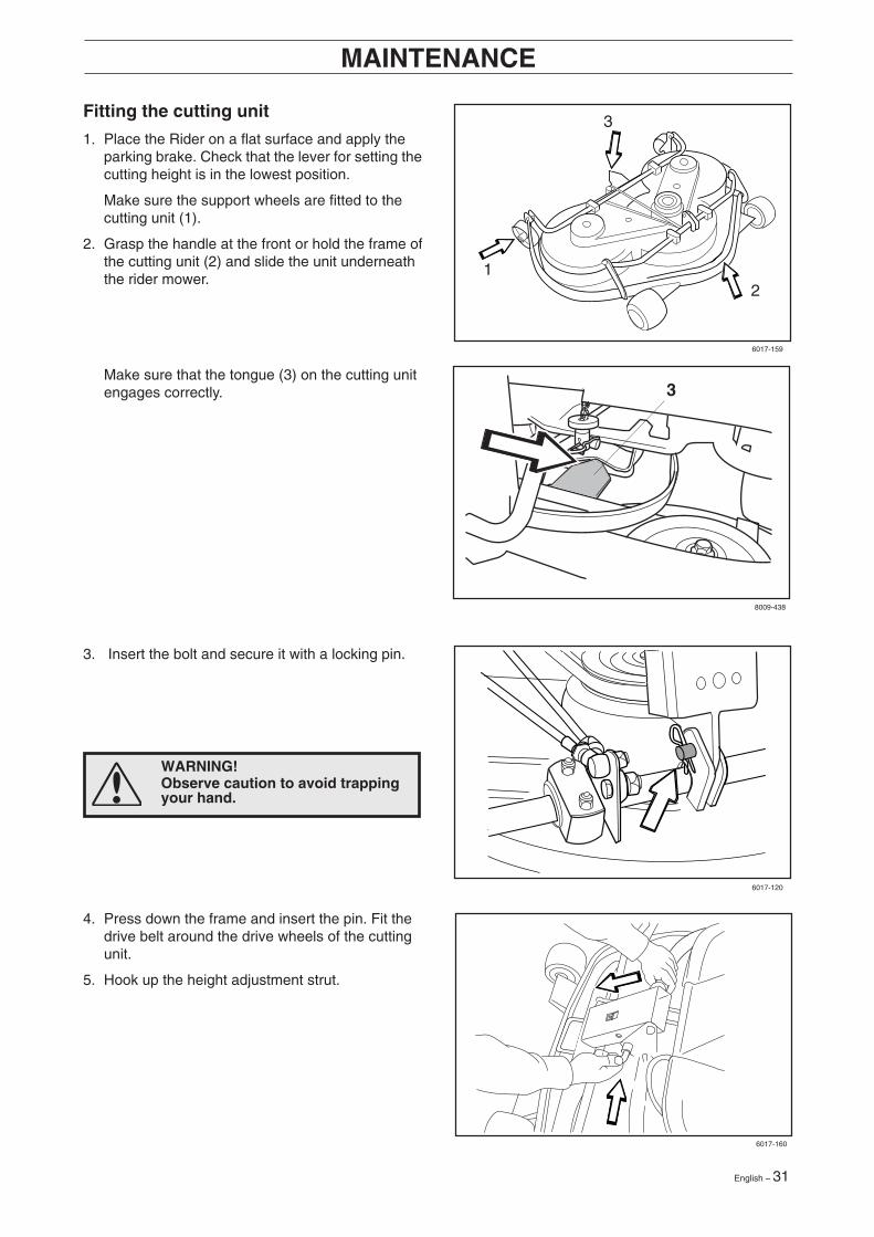
3Fitting the cutting unit
1. Place the Rider on a flat surface and apply theparking brake. Check that the lever for setting thecutting height is in the lowest position.
Make sure the support wheels are fitted to thecutting unit (1).
2. Grasp the handle at the front or hold the frame ofthe cutting unit (2) and slide the unit underneaththe rider mower.
3. Insert the bolt and secure it with a locking pin.
6017-159
6017-120
WARNING!Observe caution to avoid trappingyour hand.
8009-438
4. Press down the frame and insert the pin. Fit thedrive belt around the drive wheels of the cuttingunit.
5. Hook up the height adjustment strut.
6017-160
Make sure that the tongue (3) on the cutting unitengages correctly.

32 – English
6. Move the support wheels to their parkingposition.
7. Fit the front cover.
8009-439
8009-440
8. Secure the collet spring.
WARNING!Wear protective glasses wheninstalling or removing the cuttingunit. The collet spring whichtensions up the belt can go offand cause personal injury.
Removing the cutting unit
1. Carry out points 1-9 to put the cutting unit in theservice position, see “Service position for thecutting unit”.
2. Remove the bolt (3) and lift off the cutting unit.
2
3
1
6017-021
MAINTENANCE

English – 33
MAINTENANCE
Checking and adjustment of the cuttingunit’s ground pressure
To achieve the best cutting results the cutting unitshould follow the underlying surface withoutpressing too hard against it.
The pressure is adjusted with a screw on each sideof the machine.
1. Check the air pressure in the tyres 60 kPa(0.6 kp/cm2/8.5 PSI).
2. Place the Rider on a flat surface.
3. Put the lifting lever in the mowing position.
4. Place a set of bathroom scales under the cuttingunit’s frame (front edge) so that it rests on thescales. If necessary a block can be placedbetween the frame and scales so that thesupport wheels do not bear any weight.
5. Adjust the unit’s ground pressure by screwing inor out the adjusting screws located behind thefront wheels on both sides.
The ground pressure should be between12 and 15 kg (26.5-33 lb).
6017-216
6008-019

34 – English
MAINTENANCE
Adjusting the parallelism of the cuttingunit
1. Remove the front hood and right-hand fender.
2. Undo the nuts on the lift strut.
3. Screw out (extend) the stay to raise the rearedge of the cover.
Screw in (shorten) the stay to lower the rearedge of the cover.
4. Tighten the nuts after adjustment.
5. On completion of the adjustment the unit’sparallelism should be re-checked.
6. Fit the right-hand fender and the front hood. 6017-018
Checking the cutting unit’s parallelism
Check the parallelism of the cutting unit as follows:
1. Check the air pressure in the tyres 60 kPa(0.6 kp/cm2/8.5 PSI).
2. Place the machine on a level surface.
3. Put the lifting lever in the mowing position.
4. Measure the distance between the ground andthe front and rear edges of the cutting unit hood.The cutting unit should slope forwards slightly sothat the rear edge is 2-4 mm (1/8") higher thanthe front edge.
6017-217

English – 35
MAINTENANCE
Replacing the cutting unit belt
1. Remove the cutting unit.
2. Remove the front bolt from the parallel strut andtip the strut backwards. Push the heightadjustment strut forwards.
WARNING!Wear gloves to protect yourhands when working with theblades.
6017-154
8009-173
6017-161
4. Loosen the three bolts 1/2 - 1 turn. Press the sidesof the belt together to give maximum slack andtighten one of the bolts. Replace the belt andtighten as shown (see decal on cover). Set theblades at 90º to each other and loosen the boltagain. The spring ensures the correct belt tension.Check the positions of the blades again and adjustif necessary by repositioning the belt on the teeth.Tighten the three bolts to 45 Nm/32 lbft.
3. Loosen the two bolts holding the protective hoodand then lift off the hood.
Useful hint: Mark the positions of the blades onthe respective pulley using a felt-tip pen.
IMPORTANT INFORMATION
The blades on a Combi 103 unit should beset at 90 degrees to each other. In allother cases the blades can collide andcause serious damage to the cutting unit.
6016-111
5. Fit the protective cover over the belts andreplace the parallelism arm.

36 – English
MAINTENANCE
Service position for cutting unit
The cutting head can be placed in the serviceposition to provide easy access for cleaning, repairsand servicing. In the service position the cutting unitis raised and locked in the vertical position.
Placing in service position
1. Position the machine on flat ground. Apply theparking brake (A).Adjust the cutting unit to the lowest cuttingheight and lower the cutting unit (B).
2. Remove the front hood by removing the pin.(There are complete instructions on using theservice position inside the front hood).
3. Remove the two support wheels from under thefront hood.
8009-437
6017-219
6017-220

English – 37
MAINTENANCE
4. Fit the support wheels on either side of the rearof the cutting unit.
5. Disengage the spring for the drive belttensioning wheel.
6. Place a foot on the front edge of the cutting unitnear the wheel and raise the front edge of theunit to make it easier to remove the lift strut.
WARNING!Wear protective glasses whendismantling the cutting unit. Thespring which tensions up the beltcan go off and cause personalinjury.
6017-221
6017-222
8009-122
6017-223
7. Engage the strut in the holder.

38 – English
MAINTENANCE
Restoring from service position
To leave the service position, reverse theprocedures set out in “Placing in the serviceposition”. Make sure that the cutting unit’s ”lug” (3)enters the loop correctly on the underside of themachine, see diagram.
2
1
8. Lift off the drive belt (1). Then pull out the pin (2).
9. Pull the frame forwards and refit the pin.
10.Grasp the front edge of the cutting unit, pull outand raise into the service position.
If the cylindrical bolt, which is now holding thecutting unit is removed, the cutting unit can belifted off.
6017-225
6017-226
6017-227
8009-438
WARNING!Observe caution to avoidtrapping your hand.

English – 39
MAINTENANCE
Checking the blades
To achieve the best mowing results it is importantthat the blades are undamaged and well-sharpened.
Check that the blades’ attachment screws are tight.
IMPORTANT INFORMATION
Replacing or sharpening the bladesshould be conducted by an authorisedservice workshop.
IMPORTANT INFORMATION
Combi unit 103 should always have theblades in the relative position shown in thediagrams with an angle of 90° between theblades. Otherwise the blades can goagainst each other and damage the unit.
Combi 103
The blades should be balanced after sharpening.
Damaged blades should be replaced when hittingobstacles that result in a breakdown. Let theservicing dealer judge whether the blade can berepaired/ground or must be discarded.
8009-432
90° 90°

40 – English
MAINTENANCE
Replacing the break-pin
The blades are fitted with a break-pin to protect theCombi unit and its drive when colliding withobstacles. A domed, spring friction washer is fittedto each blade bolt. The washer must always bereplaced with a new washer if the blade bolt isloosened. Otherwise the break-pin can breakcausing the blades to collide.
Only use original spare parts. A set containing ablade, break-pin and friction washer can bepurchased from your dealer.
1. Put the cutting unit in the service position, see“Service position for the cutting unit\Placing inthe service position”.
2. Remove the blade (2A) by removing the bladebolt with washer and friction washer (2B).
3. Remove the remains of the broken break-pin (3).
4. Make sure the contact surfaces (4) on the bladeand the blade mounting are metallic clean.Clean if necessary.
5. Fit one new break-pin (5) in the blade mounting.
6. Fit the blade (6), make sure it is fitted asillustrated.
7. Fit a new friction washer (7) with the concaveface turned towards the blade.
8. Fit the blade bolt with washer (8). Tighteningtorque 45-50 Nm (4.5-5 kpm/32-36 lbft).
Removal of BioClip plug (Combi)
To change a Combi unit from BioClip function tocutting unit with rear ejection, remove the BioClipplug located under the unit with three screws.
1. Put the unit in the service position, see “Placingin the service position”.
2. Remove the three screws holding the BioClipplug, and remove the plug.
3. Tip: Fit three full-thread screws M8x15 mm inthe screw holes to protect the threads.
4. Replace the unit in normal position.
Fit the BioClip plug in the reverse order.
8009-137a
8009-289
6017-227
Removal of BioClip plug
Service position

English – 41
LUBRICATION
Changing the oil
The oil should be changed for the first time after5 hours of running time. Thereafter, it should bechanged every 100 hours of running time.
With heavy loads or high temperatures replace theoil after every 50 hours.
WARNING!Engine oil can be very hot if it isdrained off directly after theengine is stopped. Thereforeallow the engine to cool downfirst.
IMPORTANT INFORMATION
Used engine oil and oil filters arehazardous to health and environment andmust in accordance with the law not bepoured out on the ground or in the nature,and must be handed in to a workshop orother designated station for treatment.Avoid skin contact, wash with soap andwater in the event of spillage.
Check the engine’s oil level
Check the oil level in the engine when the Riderstands horizontal with the engine switched off.
Fold open the engine cover.
Release the dip stick and pull out. Wipe off the oiland insert again.
The dip stick must not be screwed down.
Now release the dip stick again and pull out. Checkthe oil level.
The oil level should lie between the markings on dipstick. If the level approaches the “ADD” mark, topup with oil to the “FULL” mark.
The oil is filled in the same hole for the dip stick.
Fill the oil slowly. Tighten the dipstick correctlybefore starting the engine. Start and run the engineat idling speed for approx. 30 seconds. Turn off theengine. Wait 30 seconds and check oil level. Ifnecessary fill so that the oil comes up to the “FULL”mark on the dipstick.
Use engine oil class SG or SH, 10W/30 abovefreezing point or 5W/30 below freezing point.
Do not mix different types of oil.
1. Place a receptacle under the engine oil drainplugs (A), located on the right-hand side of theengine.
2. Remove the dip stick and two drain plugs (A).
3. Let the oil run out into the receptacle.
4. Fit the drain plugs and tighten.
5. Fill up with oil to the “FULL” mark on the dipstick. The oil is filled in the same hole for the dipstick.See “Check the engine’s oil level” above forfilling instructions. The engine holds 1.9 litres(1.8 USqt) of oil.
6. Run the engine warm and then check that thereis no leakage from the drain plugs.
8009-471
8009-464
8009-465

42 – English
LUBRICATION
Lubricating the belt adjuster
The belt adjuster should be lubricated regularlyusing good quality molybdenum disulphidegrease*.1 nipple from the right-hand side under the engine’slower belt pulley, until grease is forced out.
With daily use lubrication should be conductedtwice a week.
General lubrication
All joints and bearings are lubricated onmanufacture with molybdenum sulphide grease.Re-grease with same type of grease*. Lubricate thesteering and control wires with engine oil.
The machine should be lubricated regularly, andtwice a week when used daily.
Check the transmission’s oil level
1. Remove the transmission cover. Loosen bothscrews (one on each side) and lift off thetransmission cover.
2. Check that there is oil in the transmission’s oiltank. Fill if necessary with engine oilSAE 10W/30 (class SF–CC).
6008-039H
6008-240H
6008-232
* Grease from well-known brand names (petrolcompanies, etc.) usually maintains a good quality.The most important property is that the greaseprovides good protection against corrosion.
8009-466
Change of oil filter
Replace oil filter every 200 operating hours. Drainoil first using the plug on the filter base. Removethe old filter using an oil filter tool. Lightly coatrubber gasket with new oil, then install filter byturning it to the right until hand tight. Tighten thefilter an additional 1/2 turn. Check that the drainplug is reinstalled before starting the engine.
Start engine and check for leakage.

English – 43
Problem Procedure
Engine will not start. • Fuel tank empty.• Spark plug defective.• Spark plug connection defective.• Dirt in carburettor or fuel pipe.
Starter does not pull round engine. • Battery flat.• Bad contact between cable and battery terminal.• Lift lever for cutting unit in wrong position.• Main fuse blown. The fuse is placed in front of the
battery, under the battery cover.• Ignition lock faulty.• Gear shift/hydrostat pedal not in neutral.• Hydrostat pedals not in the neutral position.• Faulty starter or starter circuit
Engine does not run smoothly. • Spark plug defective.• Carburettor incorrectly set.• Air filter clogged.• Fuel tank vent blocked.• Ignition setting defective.• Dirt in carburettor or fuel pipe.• Choking or incorrectly adjusted throttle cable.
Engine seems to have no power. • Air filter clogged.• Spark plug defective.• Dirt in carburettor or fuel pipe.• Carburettor incorrectly set.• Choking or incorrectly adjusted throttle cable
Engine overheats. • Engine overloaded.• Air intake or cooling flanges blocked.• Fan damaged.• Too little or no oil in engine.• Ignition defective.• Spark plug defective.
Battery does not charge. • One or more cells faulty.• Bad contact between battery terminals and cables.
Machine vibrates. • Blades are loose.• Engine is loose.• Imbalance on one or more blades, resulting from
damage or inferior balancing after sharpening.
Uneven mowing. • Blades blunt.• Cutting unit skew.• Long or wet grass.• Grass blockage under hood.• Different tyre pressures on right and left sides.• Over-speeding.• Drive belts slipping.• The blade has a broken break-pin.
TROUBLE SHOOTING SCHEDULE

44 – English
Winter storage
At the end of the season the machine shouldimmediately be put in order for storage, also if it isgoing to stand idle for more than 30 days. Fuelwhich is left to stand for long periods (30 days ormore) can leave tacky deposits which can blockthe carburettor and interfere with the engine.
Fuel stabiliser is an acceptable alternative to avoidtacky deposits during storage. Add stabiliser to thefuel in the tank or the storage container. Always usethe mixing ratios indicated by the manufacturer.Run the engine for at least 10 minutes after addingthe stabiliser so that it will reach the carburettor. Donot empty the fuel tank and carburettor if stabiliserhas been added.
STORAGE
WARNING!Never place an engine with fuel inthe tank indoors or in poorlyventilated areas where petrolfumes can come into contact withnaked flames, sparks or pilotflames in boilers, hot waterheaters, or drying cabinets, etc. Itis highly inflammable andnegligent usage can causesevere person injury and materialdamage. Drain off the fuel in anapproved container outdoors andwell clear of naked flames. Neveruse petrol for cleaning purposes.Use degreasing agents and hotwater instead.
To put the machine in order for storage follow theseinstructions:
1. Carefully clean the machine, especially underthe cutting unit. Touch-up paint damage to avoidrust.
2. Inspect the machine for worn or damaged partsand tighten loose screws and nuts.
3. Change the oil, and take care of the waste oil.
4. Empty the fuel tank. Start the engine and run ituntil the carburettor is emptied of fuel.
5. Remove the spark plug and pour about atablespoon of engine oil in the cylinder. Turnover the engine so that the oil is evenlydistributed and then refit the spark plug.
6. Grease all grease nipples, joints and axles.
7. Remove the battery. Clean it, charge it, andstore it is a cool place.
8. Store the machine is a clean and dry place andcover it over for extra protection.
Cover
There is a cover to protect your machine duringstorage or transport. Contact your dealer for ademonstration.
Service
When ordering spare parts state the purchase year,model, type, and serial number.
Always use genuine parts.
Annual inspection or trimming by an authorisedservice workshop is a good way of getting the bestout of your machine the next season.
6017-213

English – 45
Dimensions Rider 155
Length incl. cutting unit 2200 mm/7.22 ftWidth incl. cutting unit 1110 mm/3.64 ftHeight 1060 mm/3.52 ftWeight 282 kg/622 lb including Combi 103 unitWheel base 855 mm/2.8 ftTrack Front 715 mm/2.34 ft, rear 625 mm/2.05 ftTyre size 16 x 6.50 x 8Tyre pressure, front 60 kPa (0.6 kp/cm2/8.5 PSI)& rearMax. gradient 15°
Engine
Manufacture Kohler Engines model CV15Power 11.4/15.5 kW/h.p.Displacement 426 cm3/26 cuinFuel Min. 87 octane unleaded (Research min 90 octane)
(Gasohol < 10% etyl alcohol or MTBE < 15% by volume)Tank volume 7 litres/7.4 USqtOil SAE 10W/30 (SAE 5W/30 below freezing point)
class SG or SHOil volume 1.9 litres/1.8 USqtStart Electric starter
Noise emissions and cutting width
Measured noise level 100 dB(A)Guaranteed noise level 100 dB(A)Cutting width 1030 mm/41"
Electrical system
Type 12 V, negative groundBattery 12 V 24 Ah, maintenance freeSpark plug Champion RC12YC electrode gap = 1.02 mm/0.040"
Transmission
Manufacture Tuff Torq K46Oil SAE 10W/30, class SF-CC
Cutting unit
Type 3-blade unit with Combi functionCutting width 1030 mm/41"Cutting heights 9 positions, 45-95 mm/1 3/4"-3 3/4"Blade diameter 410 mm/16 1/4"
TECHNICAL DATA
We reserve the right to change technical specifications without prior notice.
Note that no legal claims are valid on the basis of information in this manual.
Use only genuine parts for repairs. The warranty is not valid if non genuine parts are used.
When this product is worn out or no longer used it should be returned tothe dealer or other appropriate body for recycling.

46 – English
○ ○ ○ ○ ○ ○ ○ ○ ○ ○ ○ ○ ○ ○ ○ ○ ○ ○ ○ ○ ○ ○ ○ ○ ○ ○ ○ ○ ○ ○ ○ ○ ○ ○ ○ ○ ○ ○ ○ ○ ○ ○ ○ ○ ○ ○ ○ ○ ○ ○ ○ ○ ○ ○ ○ ○ ○ ○ ○ ○ ○
○ ○ ○ ○ ○ ○ ○ ○ ○ ○ ○ ○ ○ ○ ○ ○ ○ ○ ○ ○ ○ ○ ○ ○ ○ ○ ○ ○ ○ ○ ○ ○ ○ ○ ○ ○ ○ ○ ○ ○ ○ ○ ○ ○ ○ ○ ○ ○ ○ ○ ○ ○ ○ ○ ○ ○ ○ ○ ○ ○ ○
○ ○ ○ ○ ○ ○ ○ ○ ○ ○ ○ ○ ○ ○ ○ ○ ○ ○ ○ ○ ○ ○ ○ ○ ○ ○ ○ ○ ○ ○ ○ ○ ○ ○ ○ ○ ○ ○ ○ ○ ○ ○ ○ ○ ○ ○ ○ ○ ○ ○ ○ ○ ○ ○ ○ ○ ○ ○ ○ ○ ○○ ○ ○ ○ ○ ○ ○ ○ ○ ○ ○ ○ ○ ○ ○ ○ ○ ○ ○ ○ ○ ○ ○ ○ ○ ○ ○ ○ ○ ○ ○ ○ ○ ○ ○ ○ ○ ○ ○ ○ ○ ○ ○ ○ ○ ○ ○ ○ ○ ○ ○ ○ ○ ○ ○ ○ ○ ○ ○ ○ ○
○ ○ ○ ○ ○ ○ ○ ○ ○ ○ ○ ○ ○ ○ ○ ○ ○ ○ ○ ○ ○ ○ ○ ○ ○ ○ ○ ○ ○ ○ ○ ○ ○ ○ ○ ○ ○ ○ ○ ○ ○ ○ ○ ○ ○ ○ ○ ○ ○ ○ ○ ○ ○ ○ ○ ○ ○ ○ ○ ○ ○
○ ○ ○ ○ ○ ○ ○ ○ ○ ○ ○ ○ ○ ○ ○ ○ ○ ○ ○ ○ ○ ○ ○ ○ ○ ○ ○ ○ ○ ○ ○ ○ ○ ○ ○ ○ ○ ○ ○ ○ ○ ○ ○ ○ ○ ○ ○ ○ ○ ○ ○ ○ ○ ○ ○ ○ ○ ○ ○ ○ ○
○ ○ ○ ○ ○ ○ ○ ○ ○ ○ ○ ○ ○ ○ ○ ○ ○ ○ ○ ○ ○ ○ ○ ○ ○ ○ ○ ○ ○ ○ ○ ○ ○ ○ ○ ○ ○ ○ ○ ○ ○ ○ ○ ○ ○ ○ ○ ○ ○ ○ ○ ○ ○ ○ ○ ○ ○ ○ ○ ○ ○
○ ○ ○ ○ ○ ○ ○ ○ ○ ○ ○ ○ ○ ○ ○ ○ ○ ○ ○ ○ ○ ○ ○ ○ ○ ○ ○ ○ ○ ○ ○ ○ ○ ○ ○ ○ ○ ○ ○ ○ ○ ○ ○ ○ ○ ○ ○ ○ ○ ○ ○ ○ ○ ○ ○ ○ ○ ○ ○ ○ ○
○ ○ ○ ○ ○ ○ ○ ○ ○ ○ ○ ○ ○ ○ ○ ○ ○ ○ ○ ○ ○ ○ ○ ○ ○ ○ ○ ○ ○ ○ ○ ○ ○ ○ ○ ○ ○ ○ ○ ○ ○ ○ ○ ○ ○ ○ ○ ○ ○ ○ ○ ○ ○ ○ ○ ○ ○ ○ ○ ○ ○
○ ○ ○ ○ ○ ○ ○ ○ ○ ○ ○ ○ ○ ○ ○ ○ ○ ○ ○ ○ ○ ○ ○ ○ ○ ○ ○ ○ ○ ○ ○ ○ ○ ○ ○ ○ ○ ○ ○ ○ ○ ○ ○ ○ ○ ○ ○ ○ ○ ○ ○ ○ ○ ○ ○ ○ ○ ○ ○ ○ ○
○ ○ ○ ○ ○ ○ ○ ○ ○ ○ ○ ○ ○ ○ ○ ○ ○ ○ ○ ○ ○ ○ ○ ○ ○ ○ ○ ○ ○ ○ ○ ○ ○ ○ ○ ○ ○ ○ ○ ○ ○ ○ ○ ○ ○ ○ ○ ○ ○ ○ ○ ○ ○ ○ ○ ○ ○ ○ ○ ○ ○
○ ○ ○ ○ ○ ○ ○ ○ ○ ○ ○ ○ ○ ○ ○ ○ ○ ○ ○ ○ ○ ○ ○ ○ ○ ○ ○ ○ ○ ○ ○ ○ ○ ○ ○ ○ ○ ○ ○ ○ ○ ○ ○ ○ ○ ○ ○ ○ ○ ○ ○ ○ ○ ○ ○ ○ ○ ○ ○ ○ ○
○ ○ ○ ○ ○ ○ ○ ○ ○ ○ ○ ○ ○ ○ ○ ○ ○ ○ ○ ○ ○ ○ ○ ○ ○ ○ ○ ○ ○ ○ ○ ○ ○ ○ ○ ○ ○ ○ ○ ○ ○ ○ ○ ○ ○ ○ ○ ○ ○ ○ ○ ○ ○ ○ ○ ○ ○ ○ ○ ○ ○
○ ○ ○ ○ ○ ○ ○ ○ ○ ○ ○ ○ ○ ○ ○ ○ ○ ○ ○ ○ ○ ○ ○ ○ ○ ○ ○ ○ ○ ○ ○ ○ ○ ○ ○ ○ ○ ○ ○ ○ ○ ○ ○ ○ ○ ○ ○ ○ ○ ○ ○ ○ ○ ○ ○ ○ ○ ○ ○ ○ ○
○ ○ ○ ○ ○ ○ ○ ○ ○ ○ ○ ○ ○ ○ ○ ○ ○ ○ ○ ○ ○ ○ ○ ○ ○ ○ ○ ○ ○ ○ ○ ○ ○ ○ ○ ○ ○ ○ ○ ○ ○ ○ ○ ○ ○ ○ ○ ○ ○ ○ ○ ○ ○ ○ ○ ○ ○ ○ ○ ○ ○
○ ○ ○ ○ ○ ○ ○ ○ ○ ○ ○ ○ ○ ○ ○ ○ ○ ○ ○ ○ ○ ○ ○ ○ ○ ○ ○ ○ ○ ○ ○ ○ ○ ○ ○ ○ ○ ○ ○ ○ ○ ○ ○ ○ ○ ○ ○ ○ ○ ○ ○ ○ ○ ○ ○ ○ ○ ○ ○ ○ ○
○ ○ ○ ○ ○ ○ ○ ○ ○ ○ ○ ○ ○ ○ ○ ○ ○ ○ ○ ○ ○ ○ ○ ○ ○ ○ ○ ○ ○ ○ ○ ○ ○ ○ ○ ○ ○ ○ ○ ○ ○ ○ ○ ○ ○ ○ ○ ○ ○ ○ ○ ○ ○ ○ ○ ○ ○ ○ ○ ○ ○
○ ○ ○ ○ ○ ○ ○ ○ ○ ○ ○ ○ ○ ○ ○ ○ ○ ○ ○ ○ ○ ○ ○ ○ ○ ○ ○ ○ ○ ○ ○ ○ ○ ○ ○ ○ ○ ○ ○ ○ ○ ○ ○ ○ ○ ○ ○ ○ ○ ○ ○ ○ ○ ○ ○ ○ ○ ○ ○ ○ ○
○ ○ ○ ○ ○ ○ ○ ○ ○ ○ ○ ○ ○ ○ ○ ○ ○ ○ ○ ○ ○ ○ ○ ○ ○ ○ ○ ○ ○ ○ ○ ○ ○ ○ ○ ○ ○ ○ ○ ○ ○ ○ ○ ○ ○ ○ ○ ○ ○ ○ ○ ○ ○ ○ ○ ○ ○ ○ ○ ○ ○
○ ○ ○ ○ ○ ○ ○ ○ ○ ○ ○ ○ ○ ○ ○ ○ ○ ○ ○ ○ ○ ○ ○ ○ ○ ○ ○ ○ ○ ○ ○ ○ ○ ○ ○ ○ ○ ○ ○ ○ ○ ○ ○ ○ ○ ○ ○ ○ ○ ○ ○ ○ ○ ○ ○ ○ ○ ○ ○ ○ ○
○ ○ ○ ○ ○ ○ ○ ○ ○ ○ ○ ○ ○ ○ ○ ○ ○ ○ ○ ○ ○ ○ ○ ○ ○ ○ ○ ○ ○ ○ ○ ○ ○ ○ ○ ○ ○ ○ ○ ○ ○ ○ ○ ○ ○ ○ ○ ○ ○ ○ ○ ○ ○ ○ ○ ○ ○ ○ ○ ○ ○
○ ○ ○ ○ ○ ○ ○ ○ ○ ○ ○ ○ ○ ○ ○ ○ ○ ○ ○ ○ ○ ○ ○ ○ ○ ○ ○ ○ ○ ○ ○ ○ ○ ○ ○ ○ ○ ○ ○ ○ ○ ○ ○ ○ ○ ○ ○ ○ ○ ○ ○ ○ ○ ○ ○ ○ ○ ○ ○ ○ ○
○ ○ ○ ○ ○ ○ ○ ○ ○ ○ ○ ○ ○ ○ ○ ○ ○ ○ ○ ○ ○ ○ ○ ○ ○ ○ ○ ○ ○ ○ ○ ○ ○ ○ ○ ○ ○ ○ ○ ○ ○ ○ ○ ○ ○ ○ ○ ○ ○ ○ ○ ○ ○ ○ ○ ○ ○ ○ ○ ○ ○
○ ○ ○ ○ ○ ○ ○ ○ ○ ○ ○ ○ ○ ○ ○ ○ ○ ○ ○ ○ ○ ○ ○ ○ ○ ○ ○ ○ ○ ○ ○ ○ ○ ○ ○ ○ ○ ○ ○ ○ ○ ○ ○ ○ ○ ○ ○ ○ ○ ○ ○ ○ ○ ○ ○ ○ ○ ○ ○ ○ ○
○ ○ ○ ○ ○ ○ ○ ○ ○ ○ ○ ○ ○ ○ ○ ○ ○ ○ ○ ○ ○ ○ ○ ○ ○ ○ ○ ○ ○ ○ ○ ○ ○ ○ ○ ○ ○ ○ ○ ○ ○ ○ ○ ○ ○ ○ ○ ○ ○ ○ ○ ○ ○ ○ ○ ○ ○ ○ ○ ○ ○
SERVICE JOURNAL
Work done Date, mileage, stamp, sign

English – 47
○ ○ ○ ○ ○ ○ ○ ○ ○ ○ ○ ○ ○ ○ ○ ○ ○ ○ ○ ○ ○ ○ ○ ○ ○ ○ ○ ○ ○ ○ ○ ○ ○ ○ ○ ○ ○ ○ ○ ○ ○ ○ ○ ○ ○ ○ ○ ○ ○ ○ ○ ○ ○ ○ ○ ○ ○ ○ ○ ○ ○
○ ○ ○ ○ ○ ○ ○ ○ ○ ○ ○ ○ ○ ○ ○ ○ ○ ○ ○ ○ ○ ○ ○ ○ ○ ○ ○ ○ ○ ○ ○ ○ ○ ○ ○ ○ ○ ○ ○ ○ ○ ○ ○ ○ ○ ○ ○ ○ ○ ○ ○ ○ ○ ○ ○ ○ ○ ○ ○ ○ ○
○ ○ ○ ○ ○ ○ ○ ○ ○ ○ ○ ○ ○ ○ ○ ○ ○ ○ ○ ○ ○ ○ ○ ○ ○ ○ ○ ○ ○ ○ ○ ○ ○ ○ ○ ○ ○ ○ ○ ○ ○ ○ ○ ○ ○ ○ ○ ○ ○ ○ ○ ○ ○ ○ ○ ○ ○ ○ ○ ○ ○○ ○ ○ ○ ○ ○ ○ ○ ○ ○ ○ ○ ○ ○ ○ ○ ○ ○ ○ ○ ○ ○ ○ ○ ○ ○ ○ ○ ○ ○ ○ ○ ○ ○ ○ ○ ○ ○ ○ ○ ○ ○ ○ ○ ○ ○ ○ ○ ○ ○ ○ ○ ○ ○ ○ ○ ○ ○ ○ ○ ○
○ ○ ○ ○ ○ ○ ○ ○ ○ ○ ○ ○ ○ ○ ○ ○ ○ ○ ○ ○ ○ ○ ○ ○ ○ ○ ○ ○ ○ ○ ○ ○ ○ ○ ○ ○ ○ ○ ○ ○ ○ ○ ○ ○ ○ ○ ○ ○ ○ ○ ○ ○ ○ ○ ○ ○ ○ ○ ○ ○ ○
○ ○ ○ ○ ○ ○ ○ ○ ○ ○ ○ ○ ○ ○ ○ ○ ○ ○ ○ ○ ○ ○ ○ ○ ○ ○ ○ ○ ○ ○ ○ ○ ○ ○ ○ ○ ○ ○ ○ ○ ○ ○ ○ ○ ○ ○ ○ ○ ○ ○ ○ ○ ○ ○ ○ ○ ○ ○ ○ ○ ○
○ ○ ○ ○ ○ ○ ○ ○ ○ ○ ○ ○ ○ ○ ○ ○ ○ ○ ○ ○ ○ ○ ○ ○ ○ ○ ○ ○ ○ ○ ○ ○ ○ ○ ○ ○ ○ ○ ○ ○ ○ ○ ○ ○ ○ ○ ○ ○ ○ ○ ○ ○ ○ ○ ○ ○ ○ ○ ○ ○ ○
○ ○ ○ ○ ○ ○ ○ ○ ○ ○ ○ ○ ○ ○ ○ ○ ○ ○ ○ ○ ○ ○ ○ ○ ○ ○ ○ ○ ○ ○ ○ ○ ○ ○ ○ ○ ○ ○ ○ ○ ○ ○ ○ ○ ○ ○ ○ ○ ○ ○ ○ ○ ○ ○ ○ ○ ○ ○ ○ ○ ○
○ ○ ○ ○ ○ ○ ○ ○ ○ ○ ○ ○ ○ ○ ○ ○ ○ ○ ○ ○ ○ ○ ○ ○ ○ ○ ○ ○ ○ ○ ○ ○ ○ ○ ○ ○ ○ ○ ○ ○ ○ ○ ○ ○ ○ ○ ○ ○ ○ ○ ○ ○ ○ ○ ○ ○ ○ ○ ○ ○ ○
○ ○ ○ ○ ○ ○ ○ ○ ○ ○ ○ ○ ○ ○ ○ ○ ○ ○ ○ ○ ○ ○ ○ ○ ○ ○ ○ ○ ○ ○ ○ ○ ○ ○ ○ ○ ○ ○ ○ ○ ○ ○ ○ ○ ○ ○ ○ ○ ○ ○ ○ ○ ○ ○ ○ ○ ○ ○ ○ ○ ○
○ ○ ○ ○ ○ ○ ○ ○ ○ ○ ○ ○ ○ ○ ○ ○ ○ ○ ○ ○ ○ ○ ○ ○ ○ ○ ○ ○ ○ ○ ○ ○ ○ ○ ○ ○ ○ ○ ○ ○ ○ ○ ○ ○ ○ ○ ○ ○ ○ ○ ○ ○ ○ ○ ○ ○ ○ ○ ○ ○ ○
○ ○ ○ ○ ○ ○ ○ ○ ○ ○ ○ ○ ○ ○ ○ ○ ○ ○ ○ ○ ○ ○ ○ ○ ○ ○ ○ ○ ○ ○ ○ ○ ○ ○ ○ ○ ○ ○ ○ ○ ○ ○ ○ ○ ○ ○ ○ ○ ○ ○ ○ ○ ○ ○ ○ ○ ○ ○ ○ ○ ○
○ ○ ○ ○ ○ ○ ○ ○ ○ ○ ○ ○ ○ ○ ○ ○ ○ ○ ○ ○ ○ ○ ○ ○ ○ ○ ○ ○ ○ ○ ○ ○ ○ ○ ○ ○ ○ ○ ○ ○ ○ ○ ○ ○ ○ ○ ○ ○ ○ ○ ○ ○ ○ ○ ○ ○ ○ ○ ○ ○ ○
○ ○ ○ ○ ○ ○ ○ ○ ○ ○ ○ ○ ○ ○ ○ ○ ○ ○ ○ ○ ○ ○ ○ ○ ○ ○ ○ ○ ○ ○ ○ ○ ○ ○ ○ ○ ○ ○ ○ ○ ○ ○ ○ ○ ○ ○ ○ ○ ○ ○ ○ ○ ○ ○ ○ ○ ○ ○ ○ ○ ○
○ ○ ○ ○ ○ ○ ○ ○ ○ ○ ○ ○ ○ ○ ○ ○ ○ ○ ○ ○ ○ ○ ○ ○ ○ ○ ○ ○ ○ ○ ○ ○ ○ ○ ○ ○ ○ ○ ○ ○ ○ ○ ○ ○ ○ ○ ○ ○ ○ ○ ○ ○ ○ ○ ○ ○ ○ ○ ○ ○ ○
○ ○ ○ ○ ○ ○ ○ ○ ○ ○ ○ ○ ○ ○ ○ ○ ○ ○ ○ ○ ○ ○ ○ ○ ○ ○ ○ ○ ○ ○ ○ ○ ○ ○ ○ ○ ○ ○ ○ ○ ○ ○ ○ ○ ○ ○ ○ ○ ○ ○ ○ ○ ○ ○ ○ ○ ○ ○ ○ ○ ○
○ ○ ○ ○ ○ ○ ○ ○ ○ ○ ○ ○ ○ ○ ○ ○ ○ ○ ○ ○ ○ ○ ○ ○ ○ ○ ○ ○ ○ ○ ○ ○ ○ ○ ○ ○ ○ ○ ○ ○ ○ ○ ○ ○ ○ ○ ○ ○ ○ ○ ○ ○ ○ ○ ○ ○ ○ ○ ○ ○ ○
○ ○ ○ ○ ○ ○ ○ ○ ○ ○ ○ ○ ○ ○ ○ ○ ○ ○ ○ ○ ○ ○ ○ ○ ○ ○ ○ ○ ○ ○ ○ ○ ○ ○ ○ ○ ○ ○ ○ ○ ○ ○ ○ ○ ○ ○ ○ ○ ○ ○ ○ ○ ○ ○ ○ ○ ○ ○ ○ ○ ○
○ ○ ○ ○ ○ ○ ○ ○ ○ ○ ○ ○ ○ ○ ○ ○ ○ ○ ○ ○ ○ ○ ○ ○ ○ ○ ○ ○ ○ ○ ○ ○ ○ ○ ○ ○ ○ ○ ○ ○ ○ ○ ○ ○ ○ ○ ○ ○ ○ ○ ○ ○ ○ ○ ○ ○ ○ ○ ○ ○ ○
○ ○ ○ ○ ○ ○ ○ ○ ○ ○ ○ ○ ○ ○ ○ ○ ○ ○ ○ ○ ○ ○ ○ ○ ○ ○ ○ ○ ○ ○ ○ ○ ○ ○ ○ ○ ○ ○ ○ ○ ○ ○ ○ ○ ○ ○ ○ ○ ○ ○ ○ ○ ○ ○ ○ ○ ○ ○ ○ ○ ○
○ ○ ○ ○ ○ ○ ○ ○ ○ ○ ○ ○ ○ ○ ○ ○ ○ ○ ○ ○ ○ ○ ○ ○ ○ ○ ○ ○ ○ ○ ○ ○ ○ ○ ○ ○ ○ ○ ○ ○ ○ ○ ○ ○ ○ ○ ○ ○ ○ ○ ○ ○ ○ ○ ○ ○ ○ ○ ○ ○ ○
○ ○ ○ ○ ○ ○ ○ ○ ○ ○ ○ ○ ○ ○ ○ ○ ○ ○ ○ ○ ○ ○ ○ ○ ○ ○ ○ ○ ○ ○ ○ ○ ○ ○ ○ ○ ○ ○ ○ ○ ○ ○ ○ ○ ○ ○ ○ ○ ○ ○ ○ ○ ○ ○ ○ ○ ○ ○ ○ ○ ○
○ ○ ○ ○ ○ ○ ○ ○ ○ ○ ○ ○ ○ ○ ○ ○ ○ ○ ○ ○ ○ ○ ○ ○ ○ ○ ○ ○ ○ ○ ○ ○ ○ ○ ○ ○ ○ ○ ○ ○ ○ ○ ○ ○ ○ ○ ○ ○ ○ ○ ○ ○ ○ ○ ○ ○ ○ ○ ○ ○ ○
○ ○ ○ ○ ○ ○ ○ ○ ○ ○ ○ ○ ○ ○ ○ ○ ○ ○ ○ ○ ○ ○ ○ ○ ○ ○ ○ ○ ○ ○ ○ ○ ○ ○ ○ ○ ○ ○ ○ ○ ○ ○ ○ ○ ○ ○ ○ ○ ○ ○ ○ ○ ○ ○ ○ ○ ○ ○ ○ ○ ○
○ ○ ○ ○ ○ ○ ○ ○ ○ ○ ○ ○ ○ ○ ○ ○ ○ ○ ○ ○ ○ ○ ○ ○ ○ ○ ○ ○ ○ ○ ○ ○ ○ ○ ○ ○ ○ ○ ○ ○ ○ ○ ○ ○ ○ ○ ○ ○ ○ ○ ○ ○ ○ ○ ○ ○ ○ ○ ○ ○ ○
SERVICE JOURNAL
Work done Date, mileage, stamp, sign

○ ○ ○ ○ ○ ○ ○ ○ ○ ○ ○ ○ ○ ○ ○ ○ ○ ○ ○ ○ ○ ○ ○ ○ ○ ○ ○ ○ ○ ○ ○ ○ ○ ○ ○ ○ ○ ○ ○ ○ ○ ○ ○ ○ ○ ○ ○ ○ ○ ○ ○ ○ ○ ○ ○ ○ ○ ○ ○ ○ ○
○ ○ ○ ○ ○ ○ ○ ○ ○ ○ ○ ○ ○ ○ ○ ○ ○ ○ ○ ○ ○ ○ ○ ○ ○ ○ ○ ○ ○ ○ ○ ○ ○ ○ ○ ○ ○ ○ ○ ○ ○ ○ ○ ○ ○ ○ ○ ○ ○ ○ ○ ○ ○ ○ ○ ○ ○ ○ ○ ○ ○
○ ○ ○ ○ ○ ○ ○ ○ ○ ○ ○ ○ ○ ○ ○ ○ ○ ○ ○ ○ ○ ○ ○ ○ ○ ○ ○ ○ ○ ○ ○ ○ ○ ○ ○ ○ ○ ○ ○ ○ ○ ○ ○ ○ ○ ○ ○ ○ ○ ○ ○ ○ ○ ○ ○ ○ ○ ○ ○ ○ ○○ ○ ○ ○ ○ ○ ○ ○ ○ ○ ○ ○ ○ ○ ○ ○ ○ ○ ○ ○ ○ ○ ○ ○ ○ ○ ○ ○ ○ ○ ○ ○ ○ ○ ○ ○ ○ ○ ○ ○ ○ ○ ○ ○ ○ ○ ○ ○ ○ ○ ○ ○ ○ ○ ○ ○ ○ ○ ○ ○ ○
○ ○ ○ ○ ○ ○ ○ ○ ○ ○ ○ ○ ○ ○ ○ ○ ○ ○ ○ ○ ○ ○ ○ ○ ○ ○ ○ ○ ○ ○ ○ ○ ○ ○ ○ ○ ○ ○ ○ ○ ○ ○ ○ ○ ○ ○ ○ ○ ○ ○ ○ ○ ○ ○ ○ ○ ○ ○ ○ ○ ○
○ ○ ○ ○ ○ ○ ○ ○ ○ ○ ○ ○ ○ ○ ○ ○ ○ ○ ○ ○ ○ ○ ○ ○ ○ ○ ○ ○ ○ ○ ○ ○ ○ ○ ○ ○ ○ ○ ○ ○ ○ ○ ○ ○ ○ ○ ○ ○ ○ ○ ○ ○ ○ ○ ○ ○ ○ ○ ○ ○ ○
○ ○ ○ ○ ○ ○ ○ ○ ○ ○ ○ ○ ○ ○ ○ ○ ○ ○ ○ ○ ○ ○ ○ ○ ○ ○ ○ ○ ○ ○ ○ ○ ○ ○ ○ ○ ○ ○ ○ ○ ○ ○ ○ ○ ○ ○ ○ ○ ○ ○ ○ ○ ○ ○ ○ ○ ○ ○ ○ ○ ○
○ ○ ○ ○ ○ ○ ○ ○ ○ ○ ○ ○ ○ ○ ○ ○ ○ ○ ○ ○ ○ ○ ○ ○ ○ ○ ○ ○ ○ ○ ○ ○ ○ ○ ○ ○ ○ ○ ○ ○ ○ ○ ○ ○ ○ ○ ○ ○ ○ ○ ○ ○ ○ ○ ○ ○ ○ ○ ○ ○ ○
○ ○ ○ ○ ○ ○ ○ ○ ○ ○ ○ ○ ○ ○ ○ ○ ○ ○ ○ ○ ○ ○ ○ ○ ○ ○ ○ ○ ○ ○ ○ ○ ○ ○ ○ ○ ○ ○ ○ ○ ○ ○ ○ ○ ○ ○ ○ ○ ○ ○ ○ ○ ○ ○ ○ ○ ○ ○ ○ ○ ○
○ ○ ○ ○ ○ ○ ○ ○ ○ ○ ○ ○ ○ ○ ○ ○ ○ ○ ○ ○ ○ ○ ○ ○ ○ ○ ○ ○ ○ ○ ○ ○ ○ ○ ○ ○ ○ ○ ○ ○ ○ ○ ○ ○ ○ ○ ○ ○ ○ ○ ○ ○ ○ ○ ○ ○ ○ ○ ○ ○ ○
○ ○ ○ ○ ○ ○ ○ ○ ○ ○ ○ ○ ○ ○ ○ ○ ○ ○ ○ ○ ○ ○ ○ ○ ○ ○ ○ ○ ○ ○ ○ ○ ○ ○ ○ ○ ○ ○ ○ ○ ○ ○ ○ ○ ○ ○ ○ ○ ○ ○ ○ ○ ○ ○ ○ ○ ○ ○ ○ ○ ○
○ ○ ○ ○ ○ ○ ○ ○ ○ ○ ○ ○ ○ ○ ○ ○ ○ ○ ○ ○ ○ ○ ○ ○ ○ ○ ○ ○ ○ ○ ○ ○ ○ ○ ○ ○ ○ ○ ○ ○ ○ ○ ○ ○ ○ ○ ○ ○ ○ ○ ○ ○ ○ ○ ○ ○ ○ ○ ○ ○ ○
○ ○ ○ ○ ○ ○ ○ ○ ○ ○ ○ ○ ○ ○ ○ ○ ○ ○ ○ ○ ○ ○ ○ ○ ○ ○ ○ ○ ○ ○ ○ ○ ○ ○ ○ ○ ○ ○ ○ ○ ○ ○ ○ ○ ○ ○ ○ ○ ○ ○ ○ ○ ○ ○ ○ ○ ○ ○ ○ ○ ○
○ ○ ○ ○ ○ ○ ○ ○ ○ ○ ○ ○ ○ ○ ○ ○ ○ ○ ○ ○ ○ ○ ○ ○ ○ ○ ○ ○ ○ ○ ○ ○ ○ ○ ○ ○ ○ ○ ○ ○ ○ ○ ○ ○ ○ ○ ○ ○ ○ ○ ○ ○ ○ ○ ○ ○ ○ ○ ○ ○ ○
○ ○ ○ ○ ○ ○ ○ ○ ○ ○ ○ ○ ○ ○ ○ ○ ○ ○ ○ ○ ○ ○ ○ ○ ○ ○ ○ ○ ○ ○ ○ ○ ○ ○ ○ ○ ○ ○ ○ ○ ○ ○ ○ ○ ○ ○ ○ ○ ○ ○ ○ ○ ○ ○ ○ ○ ○ ○ ○ ○ ○
○ ○ ○ ○ ○ ○ ○ ○ ○ ○ ○ ○ ○ ○ ○ ○ ○ ○ ○ ○ ○ ○ ○ ○ ○ ○ ○ ○ ○ ○ ○ ○ ○ ○ ○ ○ ○ ○ ○ ○ ○ ○ ○ ○ ○ ○ ○ ○ ○ ○ ○ ○ ○ ○ ○ ○ ○ ○ ○ ○ ○
○ ○ ○ ○ ○ ○ ○ ○ ○ ○ ○ ○ ○ ○ ○ ○ ○ ○ ○ ○ ○ ○ ○ ○ ○ ○ ○ ○ ○ ○ ○ ○ ○ ○ ○ ○ ○ ○ ○ ○ ○ ○ ○ ○ ○ ○ ○ ○ ○ ○ ○ ○ ○ ○ ○ ○ ○ ○ ○ ○ ○
○ ○ ○ ○ ○ ○ ○ ○ ○ ○ ○ ○ ○ ○ ○ ○ ○ ○ ○ ○ ○ ○ ○ ○ ○ ○ ○ ○ ○ ○ ○ ○ ○ ○ ○ ○ ○ ○ ○ ○ ○ ○ ○ ○ ○ ○ ○ ○ ○ ○ ○ ○ ○ ○ ○ ○ ○ ○ ○ ○ ○
○ ○ ○ ○ ○ ○ ○ ○ ○ ○ ○ ○ ○ ○ ○ ○ ○ ○ ○ ○ ○ ○ ○ ○ ○ ○ ○ ○ ○ ○ ○ ○ ○ ○ ○ ○ ○ ○ ○ ○ ○ ○ ○ ○ ○ ○ ○ ○ ○ ○ ○ ○ ○ ○ ○ ○ ○ ○ ○ ○ ○
○ ○ ○ ○ ○ ○ ○ ○ ○ ○ ○ ○ ○ ○ ○ ○ ○ ○ ○ ○ ○ ○ ○ ○ ○ ○ ○ ○ ○ ○ ○ ○ ○ ○ ○ ○ ○ ○ ○ ○ ○ ○ ○ ○ ○ ○ ○ ○ ○ ○ ○ ○ ○ ○ ○ ○ ○ ○ ○ ○ ○
○ ○ ○ ○ ○ ○ ○ ○ ○ ○ ○ ○ ○ ○ ○ ○ ○ ○ ○ ○ ○ ○ ○ ○ ○ ○ ○ ○ ○ ○ ○ ○ ○ ○ ○ ○ ○ ○ ○ ○ ○ ○ ○ ○ ○ ○ ○ ○ ○ ○ ○ ○ ○ ○ ○ ○ ○ ○ ○ ○ ○
○ ○ ○ ○ ○ ○ ○ ○ ○ ○ ○ ○ ○ ○ ○ ○ ○ ○ ○ ○ ○ ○ ○ ○ ○ ○ ○ ○ ○ ○ ○ ○ ○ ○ ○ ○ ○ ○ ○ ○ ○ ○ ○ ○ ○ ○ ○ ○ ○ ○ ○ ○ ○ ○ ○ ○ ○ ○ ○ ○ ○
○ ○ ○ ○ ○ ○ ○ ○ ○ ○ ○ ○ ○ ○ ○ ○ ○ ○ ○ ○ ○ ○ ○ ○ ○ ○ ○ ○ ○ ○ ○ ○ ○ ○ ○ ○ ○ ○ ○ ○ ○ ○ ○ ○ ○ ○ ○ ○ ○ ○ ○ ○ ○ ○ ○ ○ ○ ○ ○ ○ ○
○ ○ ○ ○ ○ ○ ○ ○ ○ ○ ○ ○ ○ ○ ○ ○ ○ ○ ○ ○ ○ ○ ○ ○ ○ ○ ○ ○ ○ ○ ○ ○ ○ ○ ○ ○ ○ ○ ○ ○ ○ ○ ○ ○ ○ ○ ○ ○ ○ ○ ○ ○ ○ ○ ○ ○ ○ ○ ○ ○ ○
○ ○ ○ ○ ○ ○ ○ ○ ○ ○ ○ ○ ○ ○ ○ ○ ○ ○ ○ ○ ○ ○ ○ ○ ○ ○ ○ ○ ○ ○ ○ ○ ○ ○ ○ ○ ○ ○ ○ ○ ○ ○ ○ ○ ○ ○ ○ ○ ○ ○ ○ ○ ○ ○ ○ ○ ○ ○ ○ ○ ○
SERVICE JOURNAL
Work done Date, mileage, stamp, sign
´+H-[¶5c¨

English – 49

114 01 35-95
2002W39´+H-[¶5c¨