operator´s manual rider proflex 21 - hsqglobal€¦ · presentation ... the last chapter in the...
TRANSCRIPT

Operator´s manual
Rider ProFlex 21
Please read these instructions carefully and make sureyou understand them before using the machine. English

Svenska – 31
Sve-5 225/232/235 Bruk 97-11-25, 08.4631
English – 1
Operator’s Manual forRider ProFlex 21
CONTENTS
IMPORTANT INFORMATION
Read through these instructions carefullyso that you know how to use and maintainthe machine before using it.
For servicing other than described in thismanual contact an authorised dealer forparts and service.
Introduction ......................................................... 2Driving and transport on public roads .............. 2Towing .............................................................. 2Use ................................................................... 2Serial number ................................................... 3
Explanation of symbols ...................................... 4Safety instructions .............................................. 5
General use ..................................................... 5Driving on slopes ............................................. 7Children ............................................................ 8Maintenance .................................................... 8Transport ........................................................ 10
Presentation ...................................................... 11Location of the controls .................................. 11Throttle control ............................................... 12Choke lever .................................................... 12Speed limiter .................................................. 12Cutting unit ..................................................... 13Lift lever for cutting unit .................................. 13Lever for adjustment of cutting height ............ 14Parking brake ................................................. 14Seat ................................................................ 14Fuelling .......................................................... 14
Driving ................................................................ 15Before starting ................................................ 15Starting the engine ......................................... 15Driving the machine ....................................... 16Cutting tips ..................................................... 18Stopping the engine ....................................... 19Disengage lever ............................................. 19
Maintenance ...................................................... 20Maintenance schedule ................................... 20Dismantling of the machine hoods ................. 22Checking the engine’s cooling air intake ........ 23Checking the transmission’s air intake ........... 23Checking and adjusting the steering wires .... 24Checking and adjustment of throttle wire ....... 25Checking and adjustment of throttle wire ....... 25
Adjusting the hydrostatic wire ........................ 26Adjusting the brakes ....................................... 27Checking the tyre pressure ............................ 27Replacement of air filter ................................. 28Replacement of fuel filter ............................... 29Cleaning the pulse air filter ............................ 29Checking the fuel pump’s air filter .................. 29Checking the battery acid level ...................... 30Ignition system ............................................... 30Checking the safety system ........................... 31The parts of the cutting unit ........................... 32Fitting the cutting unit ..................................... 32Setting the parallelism .................................... 34Setting the cutting height ............................... 34Checking and adjusting the groundpressure ......................................................... 35Replacing the break-pin (BioClip) .................. 35Service position for the cutting unit ................ 36Checking the blades ....................................... 36Dismantling the cutting unit ............................ 37Removing the attachment frame .................... 39Dismantling the belts ...................................... 39Assembling the belts ...................................... 40Changing the cutting unit’s belts .................... 41Removal of BioClip plug ................................. 43Cutting unit models ........................................ 43
Lubrication ......................................................... 44Lubrication chart ............................................ 44General lubrication ......................................... 45Lubricating wires ............................................ 45Lubrication instructions according to chart .... 45
Trouble shooting schedule ............................... 50Storage ............................................................... 51
Winter storage ................................................ 51Service ........................................................... 51
Wiring diagram .................................................. 52Technical data ................................................... 53EU declaration of conformity ........................... 55Service journal .................................................. 56
2 – English
INSTRUCTION
Dear customer
Thank you for choosing a Husqvarna Rider. Husqvarna Riders are built to a unique design with a front-mounted cutting unit and a patented rear-wheel steering system. Riders are designed for maximum efficiencyeven in small or confined areas. The closely grouped controls and pedal-operated hydrostatic transmissionalso contribute to the performance of this machine.
We hope you will find this operator’s manual very useful. By following its instructions (on operation, service,maintenance, etc.) you will significantly extend the life of the machine and even its second-hand value.
When you sell your Rider, make sure you pass on the operator’s manual to the new owner. The last chapterin the operator’s manual consists of a Service Journal. Make sure that all service work and repairs arerecorded. A well-documented service history reduces the costs of seasonal maintenance and influences thesecond-hand value of the machine. Remember to take along the operator’s manual when you take the Riderto the workshop for servicing.
Travel and transport on public roads
Check the relevant road traffic regulations before driving the machine on a public road. If transporting themachine on another vehicle always use approved securing devices and make sure that the machine issecurely held.
Towing
If your machine has a hydrostatic transmission you should only tow it very short distances at low speed ifabsolutely necessary, otherwise the transmission may be damaged.
Intended use
This machine is designed solely for cutting grass on conventional lawns and other cleared and leveledground without obstacles, as rocks, stumps etc., and, in conjunction with accessories supplied by themanufacturer even for other special tasks for which instructions are delivered with the accessory. Use in anyother way is considered as contrary to the intended use. Compliance with and strict adherence to theconditions of operation, service and repair as specified by the manufacturer also constitute essentialelements of the intended use.
This machine should be operated, serviced and repaired only by persons who are familiar with its particularcharacteristics and who are acquainted with the relevant safety procedures.
Accident prevention regulations, all other generally recognised regulations on safety and occupationalmedicine, and all road traffic regulations must be observed at all times.
Any arbitrary modifications carried out to this machine may relieve the manufacturer of liability for anyresulting damage or injury
English – 3
SAFETY INSTRUCTIONS
Good service
Husqvarna products are sold all over the world and only through servicing dealers. This is to ensure that you,the customer, get the best support and service. For example, before this machine was delivered it wasinspected and adjusted by your dealer. See the certificate in the Service Journal in this manual.
When you need spare parts or advice on service issues, warranty terms, etc., contact:
This Operator’s Manual belongs tomachine with serial number:
Serial number
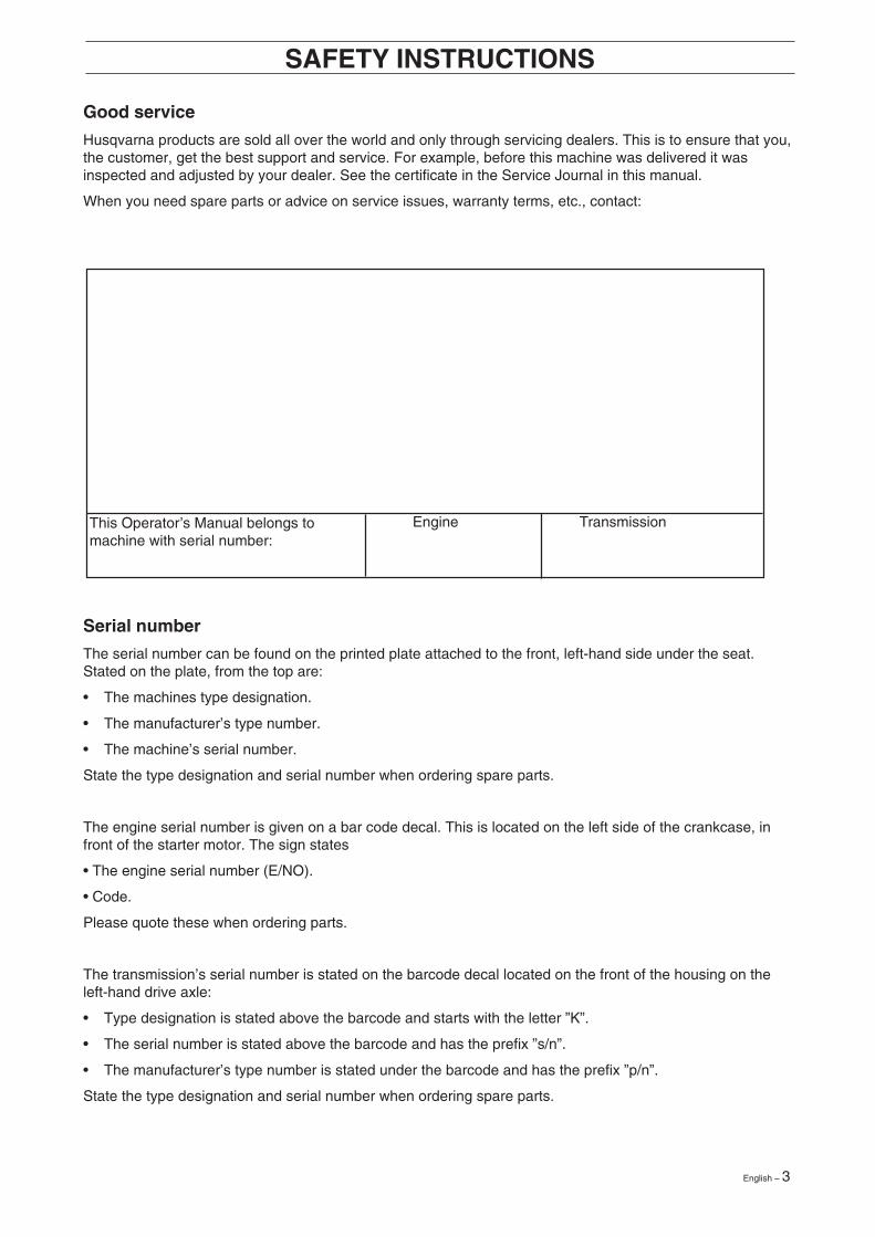
The serial number can be found on the printed plate attached to the front, left-hand side under the seat.Stated on the plate, from the top are:
• The machines type designation.
• The manufacturer’s type number.
• The machine’s serial number.
State the type designation and serial number when ordering spare parts.
The engine serial number is given on a bar code decal. This is located on the left side of the crankcase, infront of the starter motor. The sign states
• The engine serial number (E/NO).
• Code.
Please quote these when ordering parts.
The transmission’s serial number is stated on the barcode decal located on the front of the housing on theleft-hand drive axle:
• Type designation is stated above the barcode and starts with the letter ”K”.
• The serial number is stated above the barcode and has the prefix ”s/n”.
• The manufacturer’s type number is stated under the barcode and has the prefix ”p/n”.
State the type designation and serial number when ordering spare parts.
Engine Transmission
4 – English
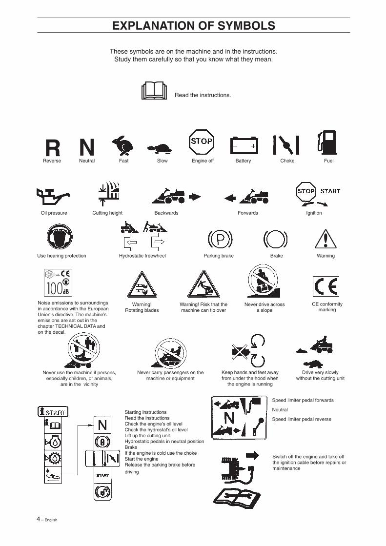
These symbols are on the machine and in the instructions.Study them carefully so that you know what they mean.
Read the instructions.
Reverse Neutral Fast Slow Engine off Battery Choke Fuel
Oil pressure Cutting height Backwards Forwards Ignition
Use hearing protection Hydrostatic freewheel Parking brake Brake Warning
Speed limiter pedal forwards
Neutral
Speed limiter pedal reverse
Switch off the engine and take offthe ignition cable before repairs ormaintenance
NR
EXPLANATION OF SYMBOLS
Starting instructionsRead the instructionsCheck the engine’s oil levelCheck the hydrostat’s oil levelLift up the cutting unitHydrostatic pedals in neutral positionBrakeIf the engine is cold use the chokeStart the engineRelease the parking brake before
driving
Keep hands and feet awayfrom under the hood when
the engine is running
Never carry passengers on themachine or equipment
Never use the machine if persons,especially children, or animals,
are in the vicinity
Drive very slowlywithout the cutting unit
CE conformitymarking
Never drive acrossa slope
Warning! Risk that themachine can tip over
Warning!Rotating blades
Noise emissions to surroundingsin accordance with the EuropeanUnion’s directive. The machine’semissions are set out in thechapter TECHNICAL DATA andon the decal.
English – 5
8010-047
6003-002
8010-052
Safety instructionsThese instructions are for your safety. Read them carefully.
General use
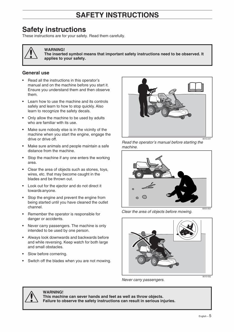
• Read all the instructions in this operator’smanual and on the machine before you start it.Ensure you understand them and then observethem.
• Learn how to use the machine and its controlssafely and learn to how to stop quickly. Alsolearn to recognize the safety decals.
• Only allow the machine to be used by adultswho are familiar with its use.
• Make sure nobody else is in the vicinity of themachine when you start the engine, engage thedrive or drive off.
• Make sure animals and people maintain a safedistance from the machine.
• Stop the machine if any one enters the workingarea.
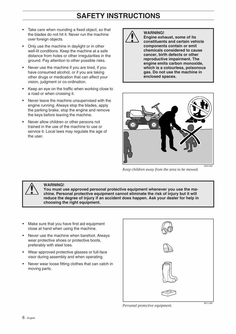
• Clear the area of objects such as stones, toys,wires, etc. that may become caught in theblades and be thrown out.
• Look out for the ejector and do not direct ittowards anyone.
• Stop the engine and prevent the engine frombeing started until you have cleaned the outletchannel.
• Remember the operator is responsible fordanger or accidents.
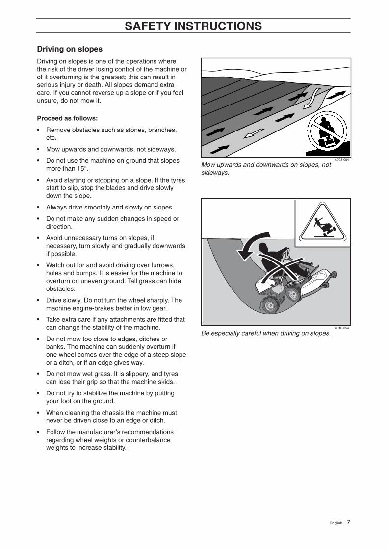
• Never carry passengers. The machine is onlyintended to be used by one person.
• Always look downwards and backwards beforeand while reversing. Keep watch for both largeand small obstacles.
• Slow before cornering.
• Switch off the blades when you are not mowing.
SAFETY INSTRUCTIONS
WARNING!This machine can sever hands and feet as well as throw objects.Failure to observe the safety instructions can result in serious injuries.
WARNING!The inserted symbol means that important safety instructions need to be observed. Itapplies to your safety.
Never carry passengers.
Read the operator’s manual before starting themachine.
Clear the area of objects before mowing.
6 – English
6003-006
8011-292
• Take care when rounding a fixed object, so thatthe blades do not hit it. Never run the machineover foreign objects.
• Only use the machine in daylight or in otherwell-lit conditions. Keep the machine at a safedistance from holes or other irregularities in theground. Pay attention to other possible risks.
• Never use the machine if you are tired, if youhave consumed alcohol, or if you are takingother drugs or medication that can affect yourvision, judgment or co-ordination.
• Keep an eye on the traffic when working close toa road or when crossing it.
• Never leave the machine unsupervised with theengine running. Always stop the blades, applythe parking brake, stop the engine and removethe keys before leaving the machine.
• Never allow children or other persons nottrained in the use of the machine to use orservice it. Local laws may regulate the age ofthe user.
SAFETY INSTRUCTIONS
WARNING!Engine exhaust, some of itsconstituents and certain vehiclecomponents contain or emitchemicals considered to causecancer, birth defects or otherreproductive impairment. Theengine emits carbon monoxide,which is a colourless, poisonousgas. Do not use the machine inenclosed spaces.
WARNING!You must use approved personal protective equipment whenever you use the ma-chine. Personal protective equipment cannot eliminate the risk of injury but it willreduce the degree of injury if an accident does happen. Ask your dealer for help inchoosing the right equipment.
• Make sure that you have first aid equipmentclose at hand when using the machine.
• Never use the machine when barefoot. Alwayswear protective shoes or protective boots,preferably with steel toes.
• Wear approved protective glasses or full-facevisor during assembly and when operating.
• Never wear loose fitting clothes that can catch inmoving parts.
Keep children away from the area to be mowed.
Personal protective equipment.
English – 7
8010-054
6003-004
Be especially careful when driving on slopes.
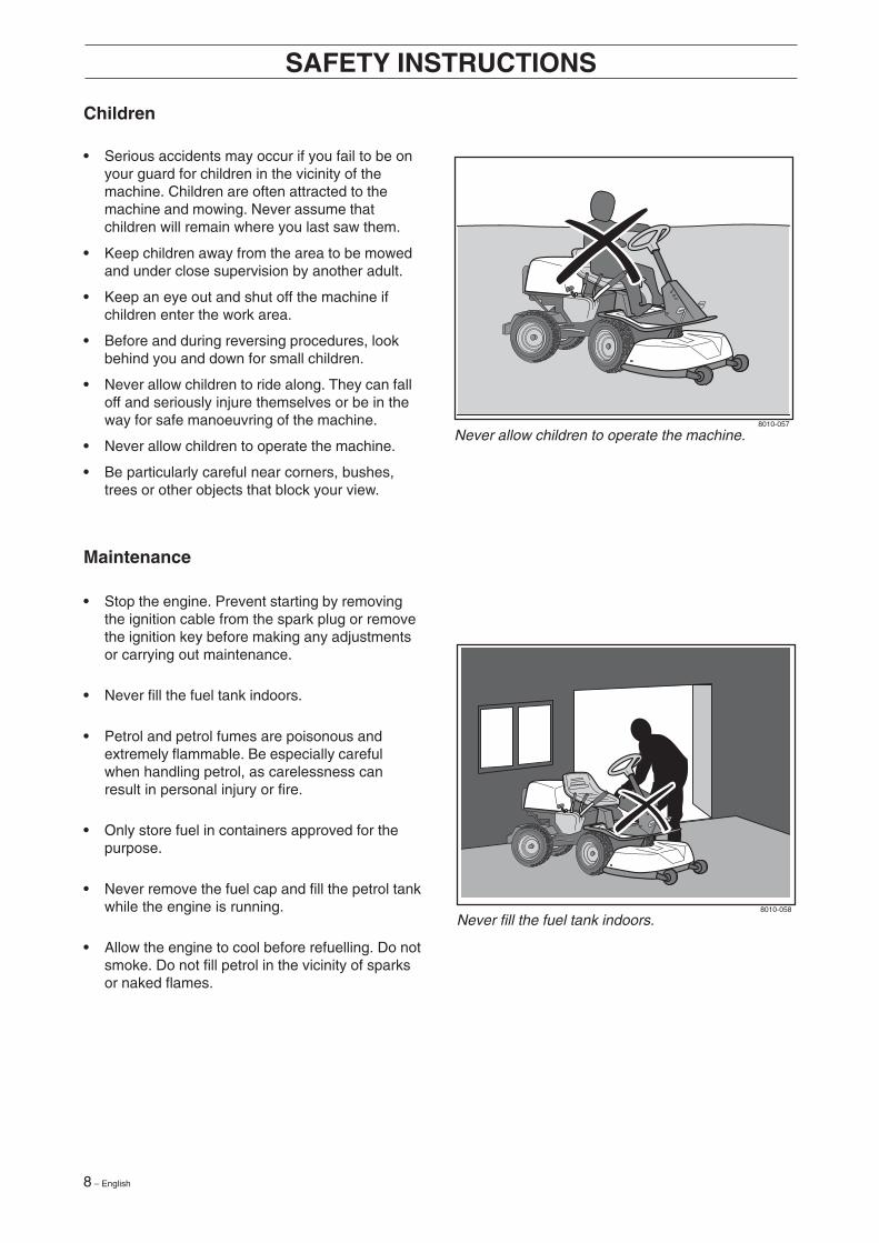
Mow upwards and downwards on slopes, notsideways.
Driving on slopes
Driving on slopes is one of the operations wherethe risk of the driver losing control of the machine orof it overturning is the greatest; this can result inserious injury or death. All slopes demand extracare. If you cannot reverse up a slope or if you feelunsure, do not mow it.
Proceed as follows:
• Remove obstacles such as stones, branches,etc.
• Mow upwards and downwards, not sideways.
• Do not use the machine on ground that slopesmore than 15°.
• Avoid starting or stopping on a slope. If the tyresstart to slip, stop the blades and drive slowlydown the slope.
• Always drive smoothly and slowly on slopes.
• Do not make any sudden changes in speed ordirection.
• Avoid unnecessary turns on slopes, ifnecessary, turn slowly and gradually downwardsif possible.
• Watch out for and avoid driving over furrows,holes and bumps. It is easier for the machine tooverturn on uneven ground. Tall grass can hideobstacles.
• Drive slowly. Do not turn the wheel sharply. Themachine engine-brakes better in low gear.
• Take extra care if any attachments are fitted thatcan change the stability of the machine.
• Do not mow too close to edges, ditches orbanks. The machine can suddenly overturn ifone wheel comes over the edge of a steep slopeor a ditch, or if an edge gives way.
• Do not mow wet grass. It is slippery, and tyrescan lose their grip so that the machine skids.
• Do not try to stabilize the machine by puttingyour foot on the ground.
• When cleaning the chassis the machine mustnever be driven close to an edge or ditch.
• Follow the manufacturer’s recommendationsregarding wheel weights or counterbalanceweights to increase stability.
SAFETY INSTRUCTIONS
8 – English
8010-057
8010-058
Children
• Serious accidents may occur if you fail to be onyour guard for children in the vicinity of themachine. Children are often attracted to themachine and mowing. Never assume thatchildren will remain where you last saw them.
• Keep children away from the area to be mowedand under close supervision by another adult.
• Keep an eye out and shut off the machine ifchildren enter the work area.
• Before and during reversing procedures, lookbehind you and down for small children.
• Never allow children to ride along. They can falloff and seriously injure themselves or be in theway for safe manoeuvring of the machine.
• Never allow children to operate the machine.
• Be particularly careful near corners, bushes,trees or other objects that block your view.
SAFETY INSTRUCTIONS
Never allow children to operate the machine.
Never fill the fuel tank indoors.
Maintenance
• Stop the engine. Prevent starting by removingthe ignition cable from the spark plug or removethe ignition key before making any adjustmentsor carrying out maintenance.
• Never fill the fuel tank indoors.
• Petrol and petrol fumes are poisonous andextremely flammable. Be especially carefulwhen handling petrol, as carelessness canresult in personal injury or fire.
• Only store fuel in containers approved for thepurpose.
• Never remove the fuel cap and fill the petrol tankwhile the engine is running.
• Allow the engine to cool before refuelling. Do notsmoke. Do not fill petrol in the vicinity of sparksor naked flames.
English – 9
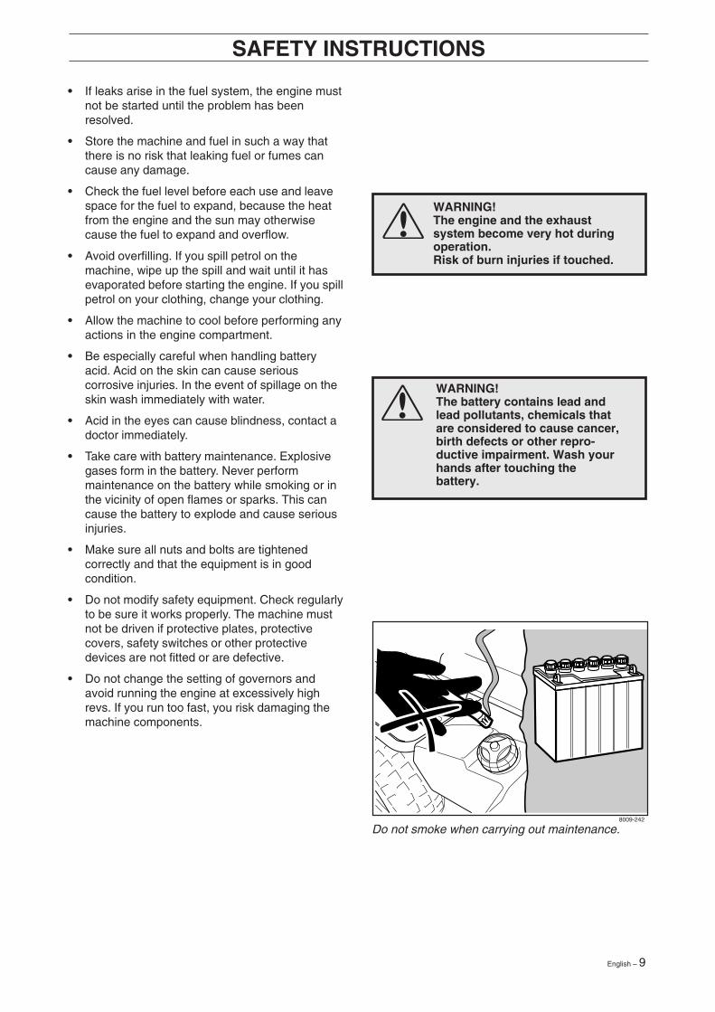
WARNING!The engine and the exhaustsystem become very hot duringoperation.Risk of burn injuries if touched.
WARNING!The battery contains lead andlead pollutants, chemicals thatare considered to cause cancer,birth defects or other repro-ductive impairment. Wash yourhands after touching thebattery.
8009-242
• If leaks arise in the fuel system, the engine mustnot be started until the problem has beenresolved.
• Store the machine and fuel in such a way thatthere is no risk that leaking fuel or fumes cancause any damage.
• Check the fuel level before each use and leavespace for the fuel to expand, because the heatfrom the engine and the sun may otherwisecause the fuel to expand and overflow.
• Avoid overfilling. If you spill petrol on themachine, wipe up the spill and wait until it hasevaporated before starting the engine. If you spillpetrol on your clothing, change your clothing.
• Allow the machine to cool before performing anyactions in the engine compartment.
• Be especially careful when handling batteryacid. Acid on the skin can cause seriouscorrosive injuries. In the event of spillage on theskin wash immediately with water.
• Acid in the eyes can cause blindness, contact adoctor immediately.
• Take care with battery maintenance. Explosivegases form in the battery. Never performmaintenance on the battery while smoking or inthe vicinity of open flames or sparks. This cancause the battery to explode and cause seriousinjuries.
• Make sure all nuts and bolts are tightenedcorrectly and that the equipment is in goodcondition.
• Do not modify safety equipment. Check regularlyto be sure it works properly. The machine mustnot be driven if protective plates, protectivecovers, safety switches or other protectivedevices are not fitted or are defective.
• Do not change the setting of governors andavoid running the engine at excessively highrevs. If you run too fast, you risk damaging themachine components.
SAFETY INSTRUCTIONS
Do not smoke when carrying out maintenance.
10 – English
8010-060
8010-061
SAFETY INSTRUCTIONS
• Never use the machine indoors or in spaceslacking proper ventilation. Exhaust fumescontain carbon monoxide, an odourless,poisonous and highly dangerous gas.
• Stop and inspect the equipment if you run overor into anything. If necessary, make repairsbefore starting.
• Never make adjustments with the enginerunning.
• The machine is tested and approved only withthe equipment originally provided orrecommended by the manufacturer.
• The blades are sharp and can cause cuts. Wrapthe blades or wear protective gloves whenhandling them.
• Check regularly that the parking brake works.Adjust and maintain as required.
• The mulching unit should only be used wherebetter quality mowing is required and in knownareas.
• Reduce the risk of fire by removing grass, leavesand other debris that may have fastened on themachine. Allow the machine to cool beforeputting it in storage.
Transport
• The machine is heavy and can cause seriouscrush injuries. Be especially careful when it isloaded in or out of a car or on and off of a trailer.
• Use an approved trailer to transport the ma-chine. Activate the parking brake, shutoff the fuelsupply and secure the machine using approvedfasteners, such as tension belts, chains or ropeswhen transporting.
• Check and observe local road traffic regulationsbefore transporting or driving the machine onroads.
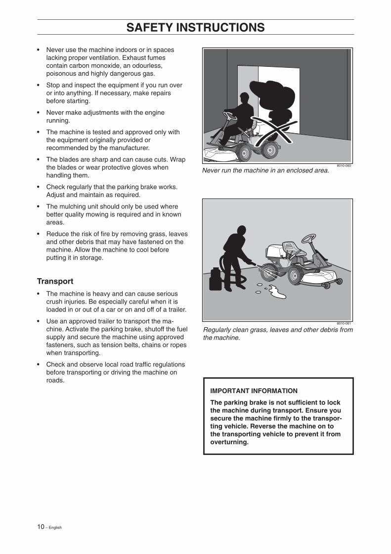
IMPORTANT INFORMATION
The parking brake is not sufficient to lockthe machine during transport. Ensure yousecure the machine firmly to the transpor-ting vehicle. Reverse the machine on tothe transporting vehicle to prevent it fromoverturning.
Regularly clean grass, leaves and other debris fromthe machine.
Never run the machine in an enclosed area.
English – 11
Presentation
These instructions describe the Rider ProFlex 21.
The Rider ProFlex 21 is equipped with a 21-horsepower four-stroke V-twin Kawasaki engine.
The power transmission from the engine is handled by a hydrostatic gearbox, which enables variable speedby using the pedals.
One pedal for driving forward and one for reverse.
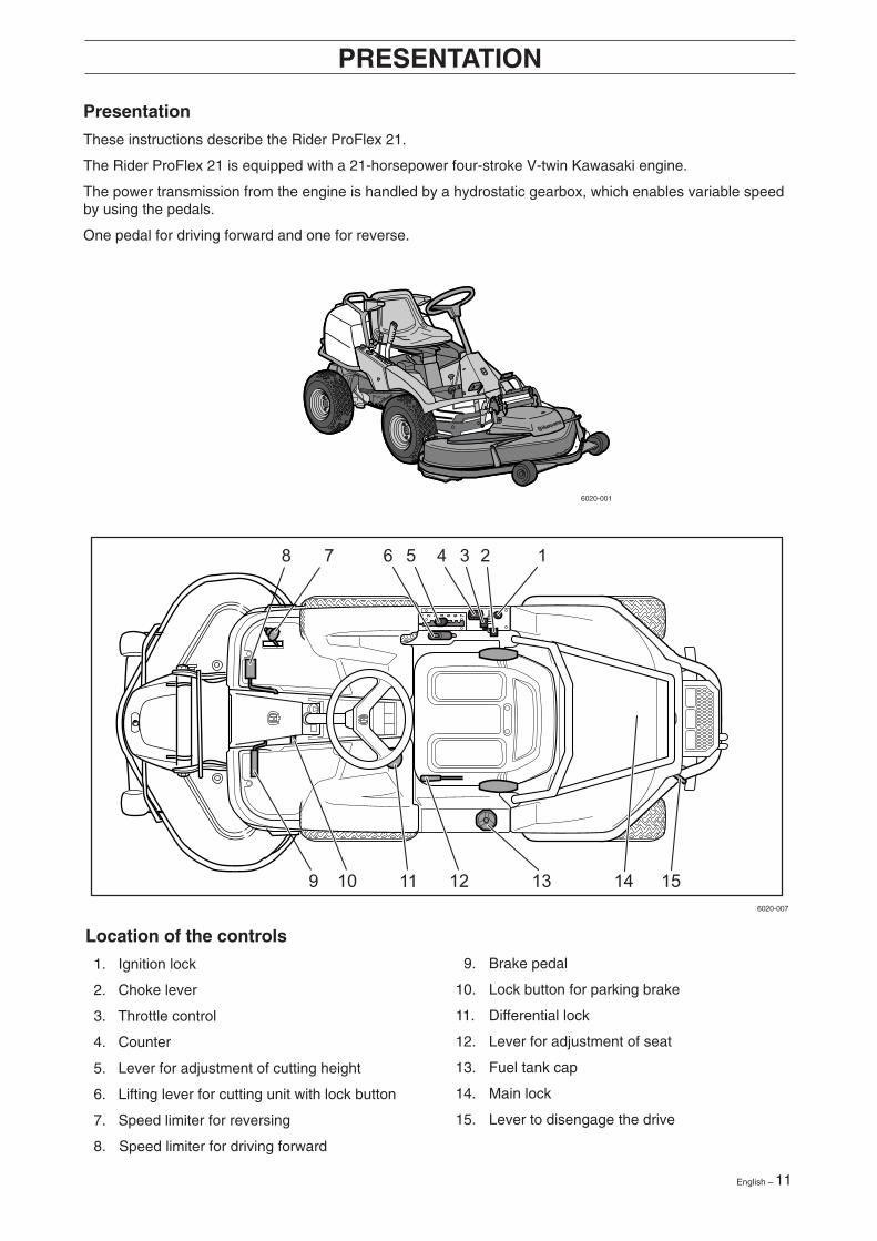
Location of the controls
1. Ignition lock
2. Choke lever
3. Throttle control
4. Counter
5. Lever for adjustment of cutting height
6. Lifting lever for cutting unit with lock button
7. Speed limiter for reversing
8. Speed limiter for driving forward
PRESENTATION
9. Brake pedal
10. Lock button for parking brake
11. Differential lock
12. Lever for adjustment of seat
13. Fuel tank cap
14. Main lock
15. Lever to disengage the drive
6020-001
6020-007
12 – English
PRESENTATION
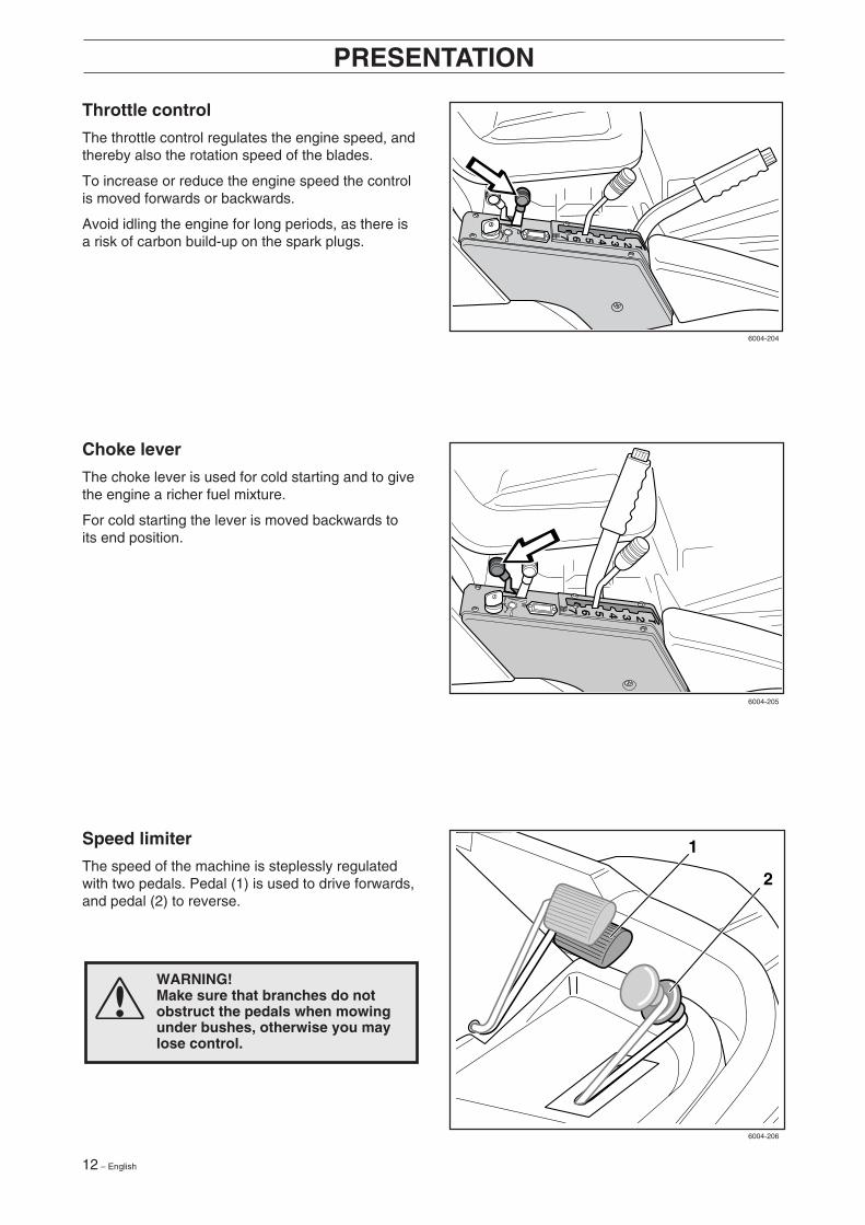
Throttle control
The throttle control regulates the engine speed, andthereby also the rotation speed of the blades.
To increase or reduce the engine speed the controlis moved forwards or backwards.
Avoid idling the engine for long periods, as there isa risk of carbon build-up on the spark plugs.
Choke lever
The choke lever is used for cold starting and to givethe engine a richer fuel mixture.
For cold starting the lever is moved backwards toits end position.
Speed limiter
The speed of the machine is steplessly regulatedwith two pedals. Pedal (1) is used to drive forwards,and pedal (2) to reverse.
WARNING!Make sure that branches do notobstruct the pedals when mowingunder bushes, otherwise you maylose control.
1
2
6004-204
6004-205
6004-206
English – 13
Cutting unit
Rider ProFlex can be equipped with numerousattachments.
The BioClip unit finely cuts the lawn by cutting thegrass several times before returning the clippings tothe lawn as fertiliser.
Cutting unit with rear ejection, i.e. the grass cuttingsare ejected behind the unit.The Combi unit functions as a BioClip unit when aBioClip plug is fitted, but can be reset to rearejection by removing the BioClip plug.For identification of the cutting unit, see ”Mainte-nance \ Cutting unit models”.
PRESENTATION
Examples of the accessories for Rider ProFlex:
• Brush
• Snow plough
• Wheel weights
• Snow chains
• Dozer
• Edger
• Electric attachment lift
• BioClip cutting unit
• Gravel rake
• Trailer
Lowering of the cutting unit
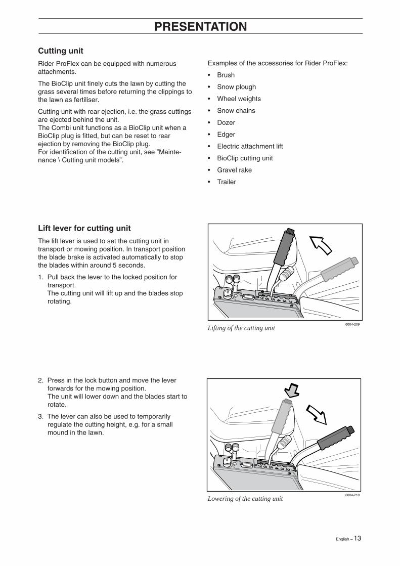
Lifting of the cutting unit
2. Press in the lock button and move the leverforwards for the mowing position.The unit will lower down and the blades start torotate.
3. The lever can also be used to temporarilyregulate the cutting height, e.g. for a smallmound in the lawn.
Lift lever for cutting unit
The lift lever is used to set the cutting unit intransport or mowing position. In transport positionthe blade brake is activated automatically to stopthe blades within around 5 seconds.
1. Pull back the lever to the locked position fortransport.
The cutting unit will lift up and the blades stoprotating.
6004-210
6004-209
14 – English
PRESENTATION
WARNING!Petrol is highly inflammable.Exercise care and refuel outdoors(see safety instructions).
Fuelling
The engine runs on unleaded petrol with aminimum octane rating of 87 (not mixed with oil).We recommend the use of biodegradable alkylatepetrol. Refer to the ”Technical data” for informationon methanol and ethanol fuels.
Seat
The seat has a jointed attachment on the front edgeand can be tipped forward.
The seat can also be adjusted lengthways.
To adjust move the lever under the front edge of theseat to the left, so that the seat can be movedforward or backwards to the required position.
Parking brake
The parking brake is applied as follows:
1. Push down the brake pedal.
2. Fully depress the lock button on the steeringcolumn.
3. Release the brake pedal while holding thebutton pressed.
The parking brake lock disengages automaticallywhen the brake pedal is pressed.
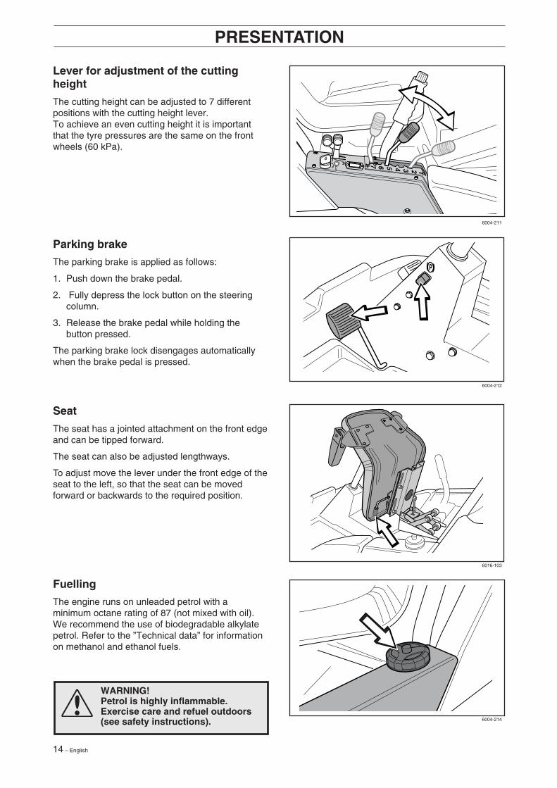
Lever for adjustment of the cuttingheight
The cutting height can be adjusted to 7 differentpositions with the cutting height lever.To achieve an even cutting height it is importantthat the tyre pressures are the same on the frontwheels (60 kPa).
6004-211
6004-212
6016-103
6004-214

English – 15
Before starting
• Read the sections headed ”Safety instructions”and ”Presentation” before starting the mower.
• Carry out daily maintenance before starting (see”Maintenance \ Maintenance Schedule”).
• Adjust the seat to the required position.
DRIVING
4. Turn the ignition key to the start position.
3. If the engine is cold move the choke leverbackwards to its end position.
2. Move the throttle control to the middle position.
Starting the engine
1. Lift up the cutting unit by pulling the lever back-wards to locked position (transport position) andapply the parking brake.
6007-201
6007-202
6007-203
6007-204
16 – English
DRIVING
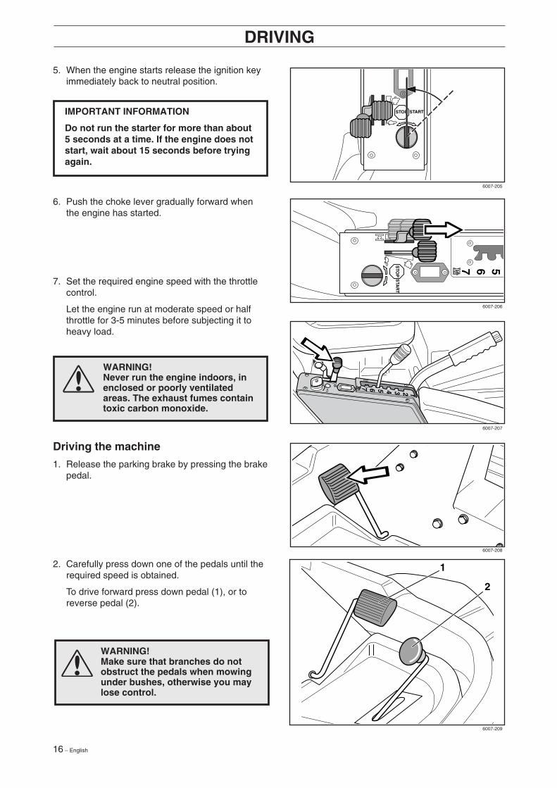
2. Carefully press down one of the pedals until therequired speed is obtained.
To drive forward press down pedal (1), or toreverse pedal (2).
Driving the machine
1. Release the parking brake by pressing the brakepedal.
7. Set the required engine speed with the throttlecontrol.
Let the engine run at moderate speed or halfthrottle for 3-5 minutes before subjecting it toheavy load.
6. Push the choke lever gradually forward whenthe engine has started.
5. When the engine starts release the ignition keyimmediately back to neutral position.
WARNING!Never run the engine indoors, inenclosed or poorly ventilatedareas. The exhaust fumes containtoxic carbon monoxide.
IMPORTANT INFORMATION
Do not run the starter for more than about5 seconds at a time. If the engine does notstart, wait about 15 seconds before tryingagain.
WARNING!Make sure that branches do notobstruct the pedals when mowingunder bushes, otherwise you maylose control.
1
2
6007-205
6007-206
6007-207
6007-208
6007-209
English – 17
3. Select the required cutting height (1–7) with thecutting height lever.
DRIVING
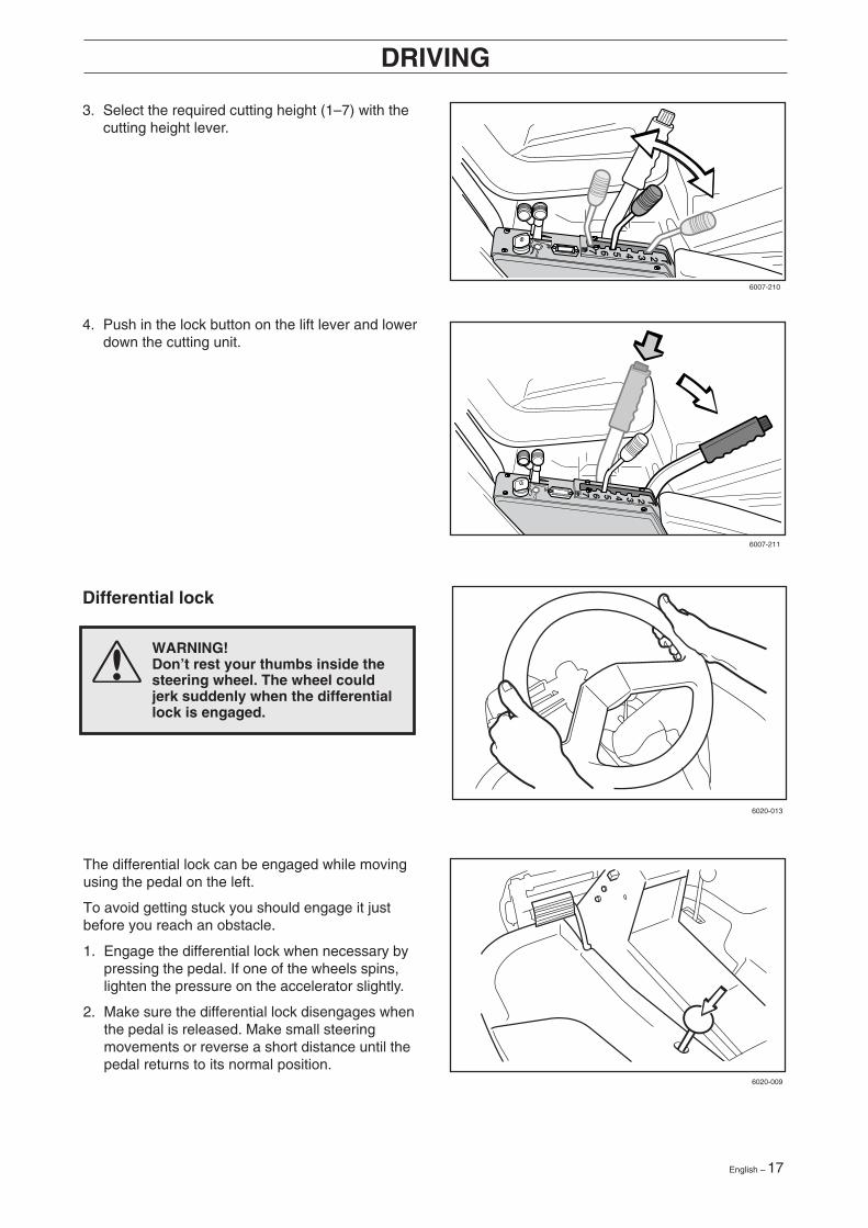
Differential lock
WARNING!Don’t rest your thumbs inside thesteering wheel. The wheel couldjerk suddenly when the differentiallock is engaged.
The differential lock can be engaged while movingusing the pedal on the left.
To avoid getting stuck you should engage it justbefore you reach an obstacle.
1. Engage the differential lock when necessary bypressing the pedal. If one of the wheels spins,lighten the pressure on the accelerator slightly.
2. Make sure the differential lock disengages whenthe pedal is released. Make small steeringmovements or reverse a short distance until thepedal returns to its normal position.
4. Push in the lock button on the lift lever and lowerdown the cutting unit.
6007-210
6007-211
6020-013
6020-009
18 – English
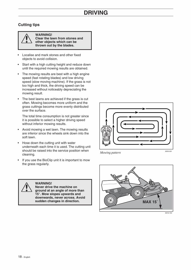
Mowing pattern
• Localise and mark stones and other fixedobjects to avoid collision.
• Start with a high cutting height and reduce downuntil the required mowing results are obtained.
• The mowing results are best with a high enginespeed (fast rotating blades) and low drivingspeed (slow moving machine). If the grass is nottoo high and thick, the driving speed can beincreased without noticeably depreciating themowing result.
• The best lawns are achieved if the grass is cutoften. Mowing becomes more uniform and thegrass cuttings become more evenly distributedover the surface.
The total time consumption is not greater sinceit is possible to select a higher driving speedwithout inferior mowing results.
• Avoid mowing a wet lawn. The mowing resultsare inferior since the wheels sink down into thesoft lawn.
• Hose down the cutting unit with waterunderneath each time it is used. The cutting unitshould be raised into the service position whencleaning.
• If you use the BioClip unit it is important to mowthe grass regularly.
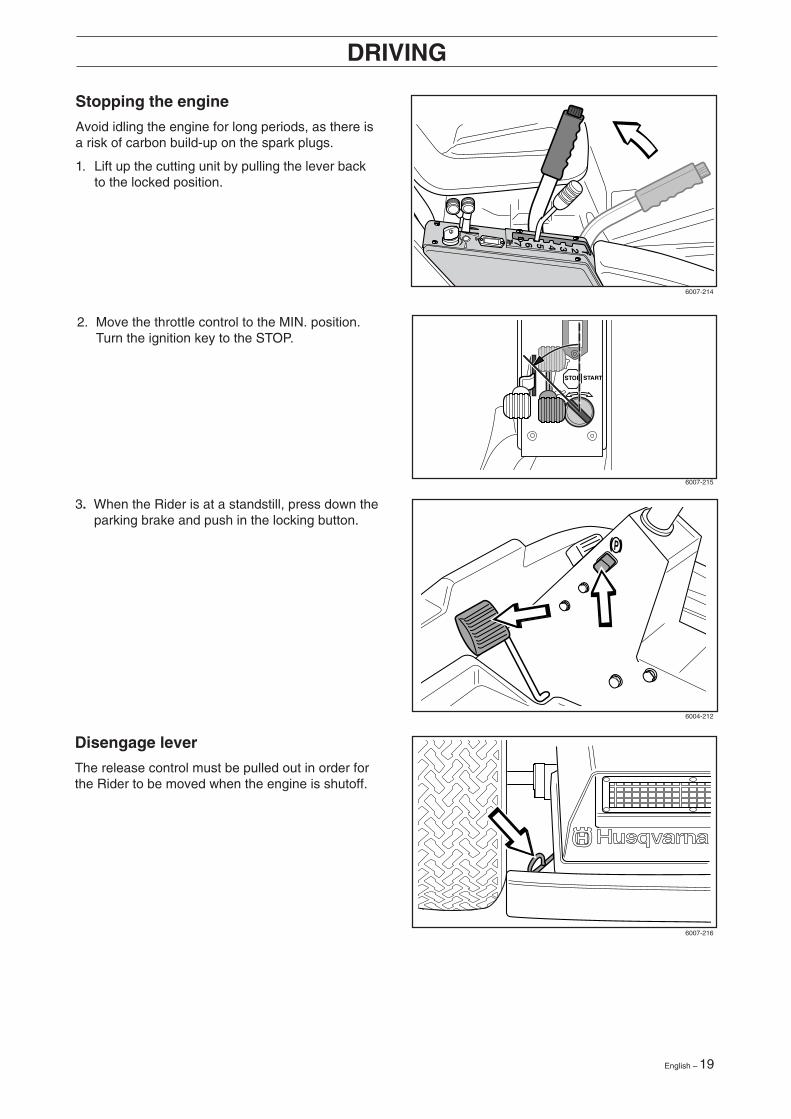
MAX 15
Cutting tips
WARNING!Clear the lawn from stones andother objects which can bethrown out by the blades.
WARNING!Never drive the machine onground at an angle of more than15°. Mow slopes upwards anddownwards, never across. Avoidsudden changes in direction.
DRIVING
6003-001
6016-104
English – 19
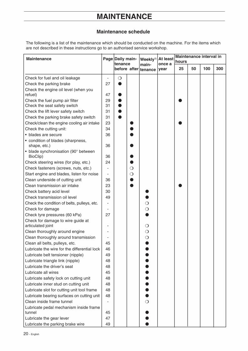
Stopping the engine
Avoid idling the engine for long periods, as there isa risk of carbon build-up on the spark plugs.
1. Lift up the cutting unit by pulling the lever backto the locked position.
DRIVING
2. Move the throttle control to the MIN. position.Turn the ignition key to the STOP.
Disengage lever
The release control must be pulled out in order forthe Rider to be moved when the engine is shutoff.
3. When the Rider is at a standstill, press down theparking brake and push in the locking button.
6007-214
6007-215
6004-212
6007-216
20 – English
MAINTENANCE
Maintenance interval inhours
Daily main-tenancebefore after
Weekly3)
main-tenance
At leastonce ayear
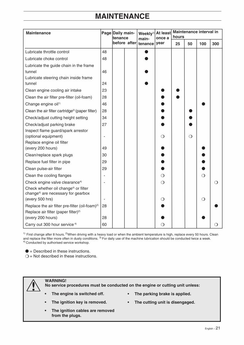
Maintenance schedule
The following is a list of the maintenance which should be conducted on the machine. For the items whichare not described in these instructions go to an authorised service workshop.
25 50 100 300
PageMaintenance
Check for fuel and oil leakage - ❍
Check the parking brake 27 ●
Check the engine oil level (when yourefuel) 47 ●
Check the fuel pump air filter 29 ● ●Check the seat safety switch 31 ●
Check the lift lever safety switch 31 ●
Check the parking brake safety switch 31 ●
Check/clean the engine cooling air intake 23 ● ●
Check the cutting unit: 34 ●
• blades are secure 36 ●
• condition of blades (sharpness,shape, etc.) 36 ●
• blade synchronisation (90° betweenBioClip) 36 ●
Check steering wires (for play, etc.) 24 ●
Check fasteners (screws, nuts, etc.) - ❍
Start engine and blades, listen for noise - ❍
Clean underside of cutting unit 36 ●
Clean transmission air intake 23 ● ●
Check battery acid level 30 ●
Check transmission oil level 49 ●
Check the condition of belts, pulleys, etc. - ❍
Check for damage - ❍
Check tyre pressures (60 kPa) 27 ●
Check for damage to wire guide atarticulated joint - ❍
Clean thoroughly around engine - ❍
Clean thoroughly around transmission - ❍
Clean all belts, pulleys, etc. 45 ●
Lubricate the wire for the differential lock 46 ●
Lubricate belt tensioner (nipple) 49 ●
Lubricate triangle link (nipple) 48 ●
Lubricate the driver’s seat 48 ●
Lubricate all wires 45 ●
Lubricate safety lock on cutting unit 48 ●
Lubricate inner stud on cutting unit 48 ●
Lubricate slot for cutting unit tool frame 48 ●
Lubricate bearing surfaces on cutting unit 48 ●
Clean inside frame tunnel - ❍
Lubricate pedal mechanism inside frametunnel 45 ●
Lubricate the gear lever 47 ●
Lubricate the parking brake wire 49 ●
English – 21
1) First change after 8 hours. 2)When driving with a heavy load or when the ambient temperature is high, replace every 50 hours. Cleanand replace the filter more often in dusty conditions. 3) For daily use of the machine lubrication should be conducted twice a week.4) Conducted by authorised service workshop.
MAINTENANCE
WARNING!No service procedures must be conducted on the engine or cutting unit unless:
● = Described in these instructions.❍ = Not described in these instructions.
Maintenance interval inhours
Daily main-tenancebefore after
Weekly3)
main-tenance
At leastonce ayear 25 50 100 300
PageMaintenance
Lubricate throttle control 48 ●
Lubricate choke control 48 ●
Lubricate the guide chain in the frame
tunnel 46 ●
Lubricate steering chain inside frametunnel 24 ●
Clean engine cooling air intake 23 ● ●
Clean the air filter pre-filter (oil-foam) 28 ● ●
Change engine oil1) 46 ● ●
Clean the air filter cartridge2) (paper filter) 28 ● ●
Check/adjust cutting height setting 34 ● ●
Check/adjust parking brake 27 ● ●
Inspect flame guard/spark arrestor(optional equipment) - ❍ ❍
Replace engine oil filter(every 200 hours) 49 ● ●
Clean/replace spark plugs 30 ● ●
Replace fuel filter in pipe 29 ● ●
Clean pulse-air filter 29 ● ●
Clean the cooling flanges - ❍ ❍
Check engine valve clearance4) - ❍ ❍
Check whether oil change4) or filterchange4) are necessary for gearbox(every 500 hrs) - ❍ ❍
Replace the air filter pre-filter (oil-foam)2) 28 ● ●
Replace air filter (paper filter)2)
(every 200 hours) 28 ● ●
Carry out 300 hour service 4) 60 ❍ ❍
• The engine is switched off.
• The ignition key is removed.
• The ignition cables are removedfrom the plugs.
• The parking brake is applied.
• The cutting unit is disengaged.
22 – English
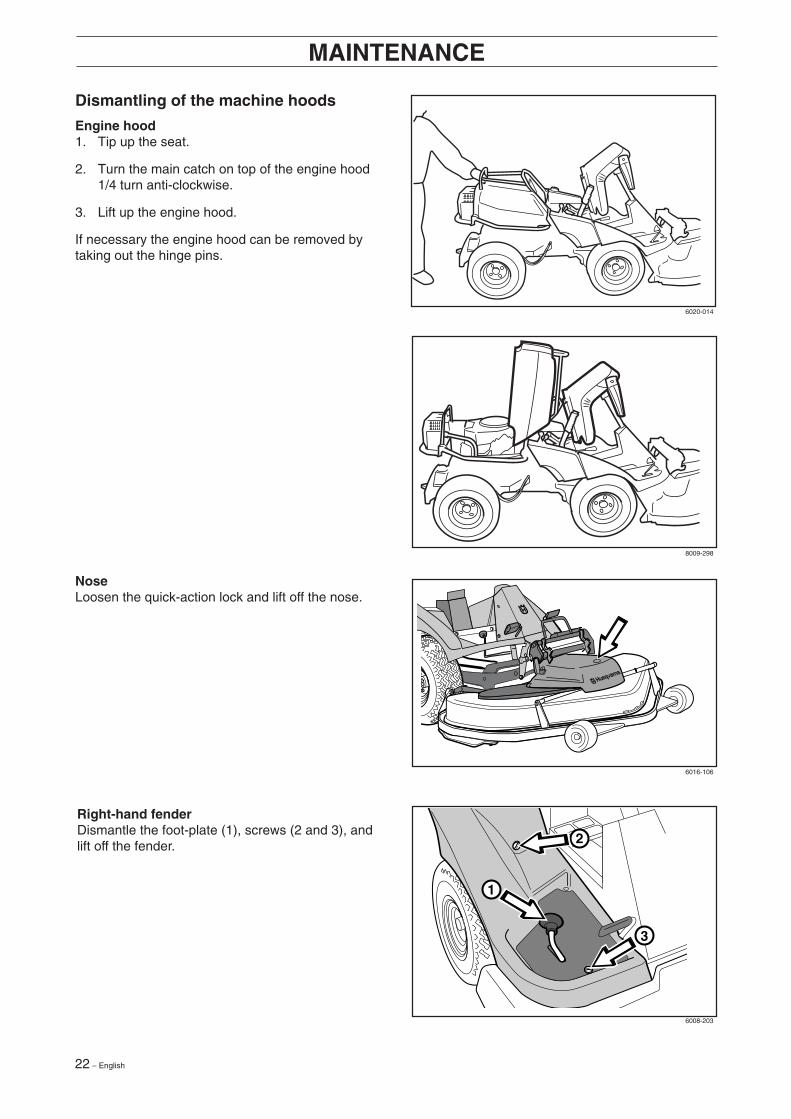
Dismantling of the machine hoods
Engine hood1. Tip up the seat.
2. Turn the main catch on top of the engine hood1/4 turn anti-clockwise.
3. Lift up the engine hood.
If necessary the engine hood can be removed bytaking out the hinge pins.
MAINTENANCE
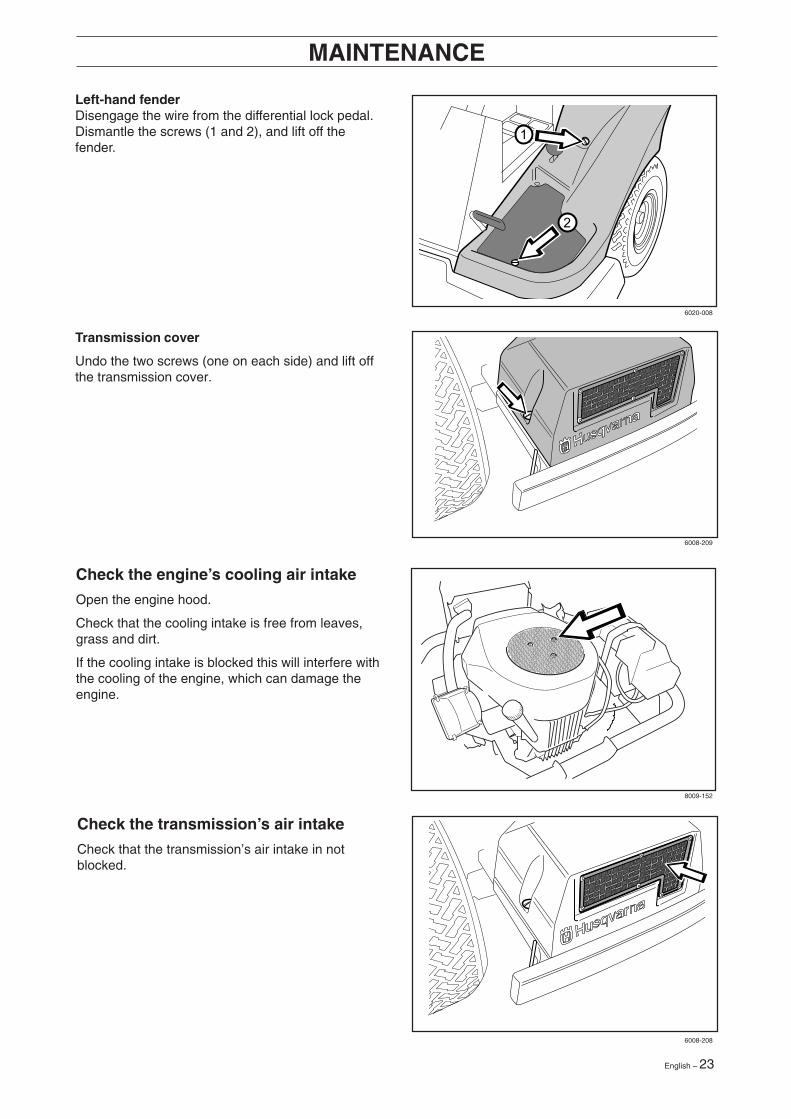
NoseLoosen the quick-action lock and lift off the nose.
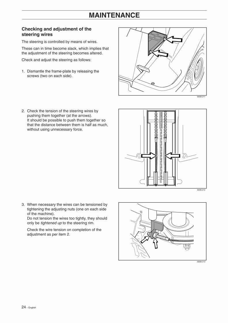
Right-hand fenderDismantle the foot-plate (1), screws (2 and 3), andlift off the fender.
1
2
3
6020-014
8009-298
6016-106
6008-203
English – 23
MAINTENANCE
Check the engine’s cooling air intake
Open the engine hood.
Check that the cooling intake is free from leaves,grass and dirt.
If the cooling intake is blocked this will interfere withthe cooling of the engine, which can damage theengine.
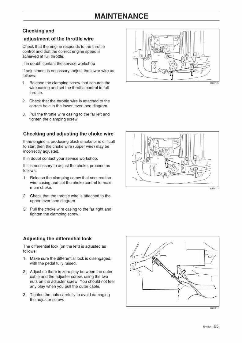
Left-hand fenderDisengage the wire from the differential lock pedal.Dismantle the screws (1 and 2), and lift off thefender.
Transmission cover
Undo the two screws (one on each side) and lift offthe transmission cover.
Check the transmission’s air intake
Check that the transmission’s air intake in notblocked.
6020-008
6008-209
8009-152
6008-208
24 – English
Checking and adjustment of thesteering wires
The steering is controlled by means of wires.
These can in time become slack, which implies thatthe adjustment of the steering becomes altered.
Check and adjust the steering as follows:
1. Dismantle the frame-plate by releasing thescrews (two on each side).
MAINTENANCE
2. Check the tension of the steering wires bypushing them together (at the arrows).It should be possible to push them together sothat the distance between them is half as much,without using unnecessary force.
3. When necessary the wires can be tensioned bytightening the adjusting nuts (one on each sideof the machine).Do not tension the wires too tightly, they shouldonly be tightened up to the steering rim.
Check the wire tension on completion of theadjustment as per item 2.
6008-211
6008-212
6008-213
English – 25
Checking and
adjustment of the throttle wire
Check that the engine responds to the throttlecontrol and that the correct engine speed isachieved at full throttle.
If in doubt, contact the service workshop
If adjustment is necessary, adjust the lower wire asfollows:
1. Release the clamping screw that secures thewire casing and set the throttle control to fullthrottle.
2. Check that the throttle wire is attached to thecorrect hole in the lower lever, see diagram.
3. Pull the throttle wire casing to the far left andtighten the clamping screw.
Checking and adjusting the choke wire
If the engine is producing black smoke or is difficultto start then the choke wire (upper wire) may beincorrectly adjusted.
If in doubt contact your service workshop.
If it is necessary to adjust the choke, proceed asfollows:
1. Release the clamping screw that secures thewire casing and set the choke control to maxi-mum choke.
2. Check that the throttle wire is attached to theupper lever, see diagram.
3. Pull the choke wire casing to the far right andtighten the clamping screw.
MAINTENANCE
Adjusting the differential lock
The differential lock (on the left) is adjusted asfollows:
1. Make sure the differential lock is disengaged,with the pedal fully raised.
2. Adjust so there is zero play between the outercable and the adjuster screw, using the twonuts on the adjuster screw. You should not feelany play when you pull the outer cable.
3. Tighten the nuts carefully to avoid damagingthe adjuster screw.
8009-176
8009-177
6020-011
26 – English
MAINTENANCE
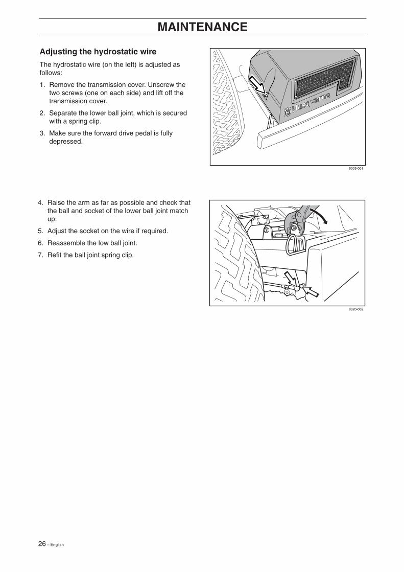
Adjusting the hydrostatic wire
The hydrostatic wire (on the left) is adjusted asfollows:
1. Remove the transmission cover. Unscrew thetwo screws (one on each side) and lift off thetransmission cover.
2. Separate the lower ball joint, which is securedwith a spring clip.
3. Make sure the forward drive pedal is fullydepressed.
4. Raise the arm as far as possible and check thatthe ball and socket of the lower ball joint matchup.
5. Adjust the socket on the wire if required.
6. Reassemble the low ball joint.
7. Refit the ball joint spring clip.
6003-001
6020-002
English – 27
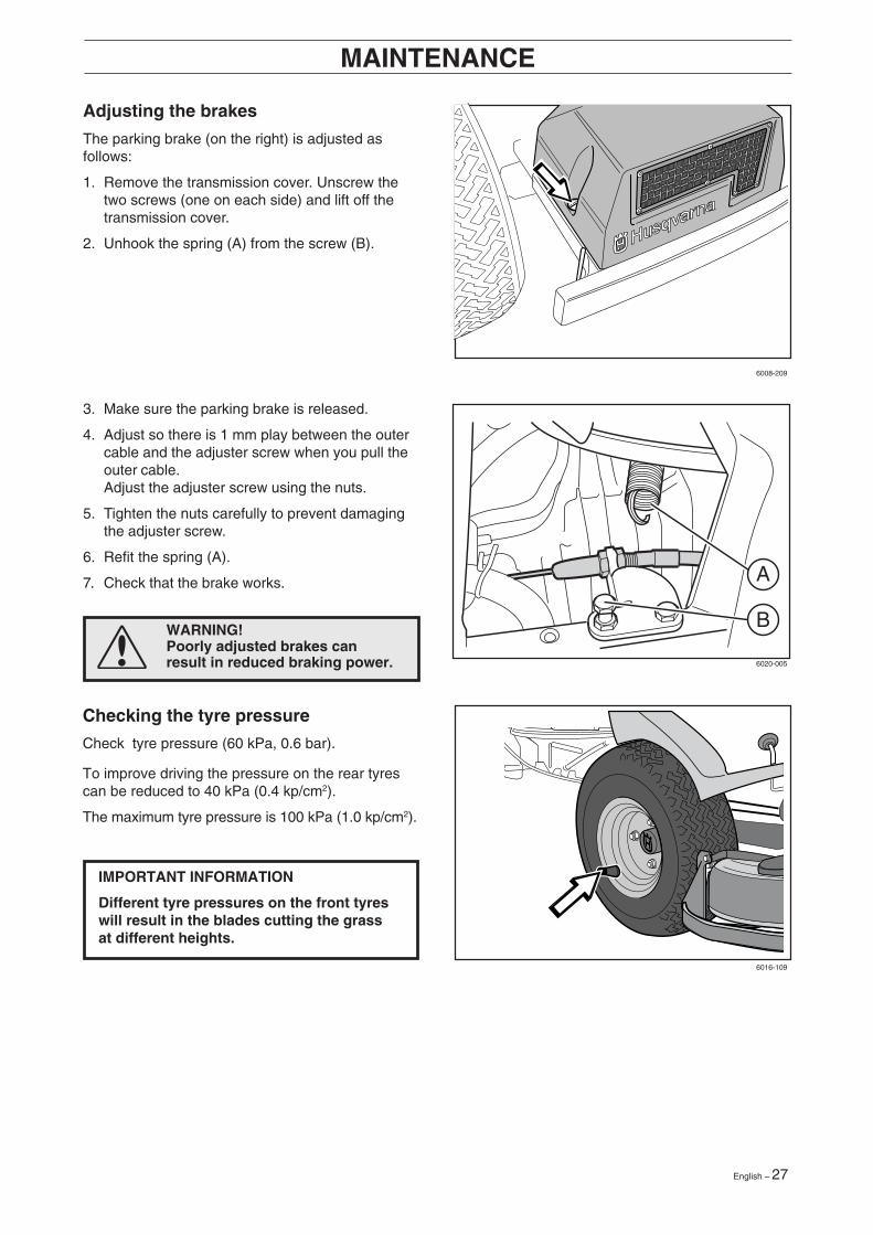
Adjusting the brakes
The parking brake (on the right) is adjusted asfollows:
1. Remove the transmission cover. Unscrew thetwo screws (one on each side) and lift off thetransmission cover.
2. Unhook the spring (A) from the screw (B).
MAINTENANCE
WARNING!Poorly adjusted brakes canresult in reduced braking power.
3. Make sure the parking brake is released.
4. Adjust so there is 1 mm play between the outercable and the adjuster screw when you pull theouter cable.Adjust the adjuster screw using the nuts.
5. Tighten the nuts carefully to prevent damagingthe adjuster screw.
6. Refit the spring (A).
7. Check that the brake works.
Checking the tyre pressure
Check tyre pressure (60 kPa, 0.6 bar).
To improve driving the pressure on the rear tyrescan be reduced to 40 kPa (0.4 kp/cm2).
The maximum tyre pressure is 100 kPa (1.0 kp/cm2).
IMPORTANT INFORMATION
Different tyre pressures on the front tyreswill result in the blades cutting the grassat different heights.
B
A
6008-209
6020-005
6016-109
28 – English
Replacing the air filter
If the engine seems to lack power or does not runsmoothly this may be because the air filter isclogged. If run with a soiled air filter, carbon canbuild-up on the spark plugs and lead tomalfunctioning.
It is therefore important to replace the air filter atregular intervals (see ”Maintenance \ MaintenanceSchedule” for correct service interval).
Clean/ replace the air filter as follows:
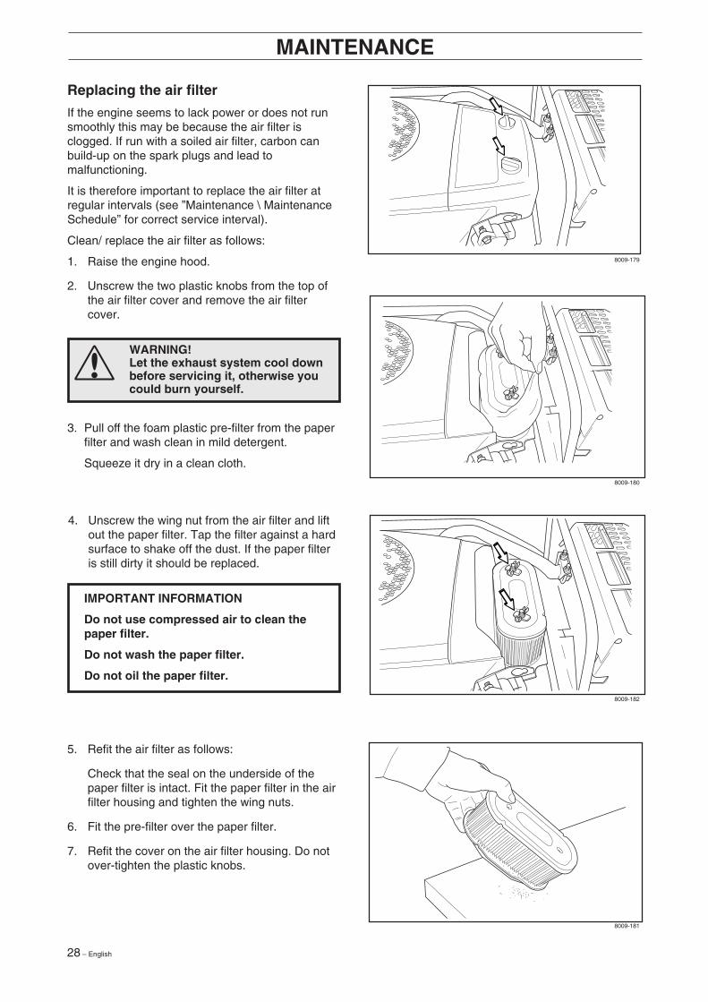
1. Raise the engine hood.
2. Unscrew the two plastic knobs from the top ofthe air filter cover and remove the air filtercover.
MAINTENANCE
3. Pull off the foam plastic pre-filter from the paperfilter and wash clean in mild detergent.
Squeeze it dry in a clean cloth.
WARNING!Let the exhaust system cool downbefore servicing it, otherwise youcould burn yourself.
5. Refit the air filter as follows:
Check that the seal on the underside of thepaper filter is intact. Fit the paper filter in the airfilter housing and tighten the wing nuts.
6. Fit the pre-filter over the paper filter.
7. Refit the cover on the air filter housing. Do notover-tighten the plastic knobs.
IMPORTANT INFORMATION
Do not use compressed air to clean thepaper filter.
Do not wash the paper filter.
Do not oil the paper filter.
4. Unscrew the wing nut from the air filter and liftout the paper filter. Tap the filter against a hardsurface to shake off the dust. If the paper filteris still dirty it should be replaced.
8009-179
8009-180
8009-182
8009-181
English – 29
MAINTENANCE
Cleaning the pulse air filter
1. Open the engine hood.
2. Loosen the four quick-action clips and lift off thecover and remove the filter.
3. Blow out the filter using compressed air.
4. Replace the filter in the cover and secure thecover using the quick-action clips. Replace theengine hood.
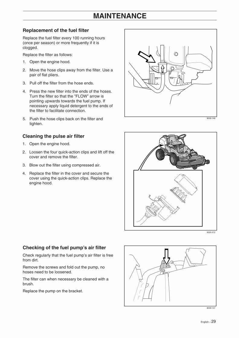
Replacement of the fuel filter
Replace the fuel filter every 100 running hours(once per season) or more frequently if it isclogged.
Replace the filter as follows:
1. Open the engine hood.
2. Move the hose clips away from the filter. Use apair of flat pliers.
3. Pull off the filter from the hose ends.
4. Press the new filter into the ends of the hoses.Turn the filter so that the ”FLOW” arrow ispointing upwards towards the fuel pump. Ifnecessary apply liquid detergent to the ends ofthe filter to facilitate connection.
5. Push the hose clips back on the filter andtighten.
Checking of the fuel pump’s air filter
Check regularly that the fuel pump’s air filter is freefrom dirt.
Remove the screws and fold out the pump, nohoses need to be loosened.
The filter can when necessary be cleaned with abrush.
Replace the pump on the bracket.
8009-146
6020-012
8009-147
30 – English
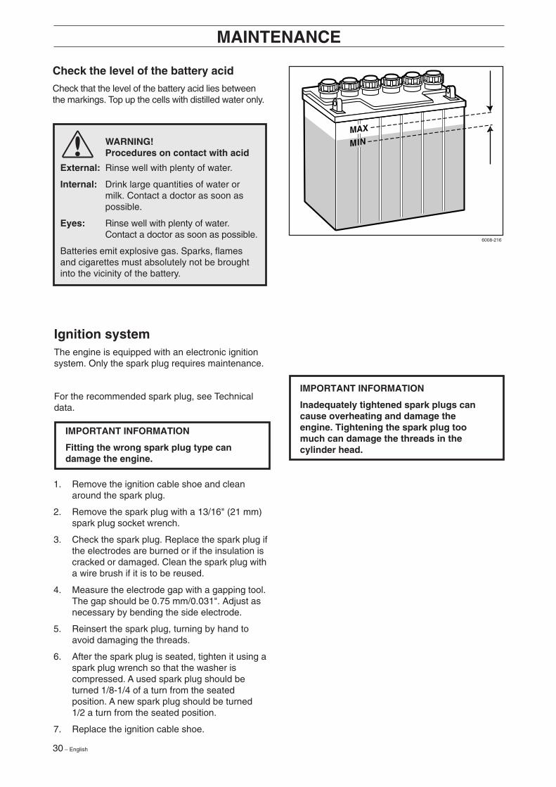
Check the level of the battery acid
Check that the level of the battery acid lies betweenthe markings. Top up the cells with distilled water only.
WARNING!Procedures on contact with acid
External: Rinse well with plenty of water.
Internal: Drink large quantities of water ormilk. Contact a doctor as soon aspossible.
Eyes: Rinse well with plenty of water.Contact a doctor as soon as possible.
Batteries emit explosive gas. Sparks, flamesand cigarettes must absolutely not be broughtinto the vicinity of the battery.
MAINTENANCE
Ignition systemThe engine is equipped with an electronic ignitionsystem. Only the spark plug requires maintenance.
For the recommended spark plug, see Technicaldata.
IMPORTANT INFORMATION
Fitting the wrong spark plug type candamage the engine.
1. Remove the ignition cable shoe and cleanaround the spark plug.
2. Remove the spark plug with a 13/16" (21 mm)spark plug socket wrench.
3. Check the spark plug. Replace the spark plug ifthe electrodes are burned or if the insulation iscracked or damaged. Clean the spark plug witha wire brush if it is to be reused.
4. Measure the electrode gap with a gapping tool.The gap should be 0.75 mm/0.031". Adjust asnecessary by bending the side electrode.
5. Reinsert the spark plug, turning by hand toavoid damaging the threads.
6. After the spark plug is seated, tighten it using aspark plug wrench so that the washer iscompressed. A used spark plug should beturned 1/8-1/4 of a turn from the seatedposition. A new spark plug should be turned1/2 a turn from the seated position.
7. Replace the ignition cable shoe.
IMPORTANT INFORMATION
Inadequately tightened spark plugs cancause overheating and damage theengine. Tightening the spark plug toomuch can damage the threads in thecylinder head.
6008-216
English – 31
MAINTENANCE
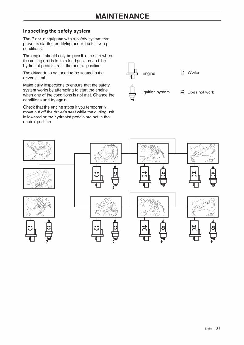
Inspecting the safety system
The Rider is equipped with a safety system thatprevents starting or driving under the followingconditions:
The engine should only be possible to start whenthe cutting unit is in its raised position and thehydrostat pedals are in the neutral position.
The driver does not need to be seated in thedriver’s seat.
Make daily inspections to ensure that the safetysystem works by attempting to start the enginewhen one of the conditions is not met. Change theconditions and try again.
Check that the engine stops if you temporarilymove out off the driver’s seat while the cutting unitis lowered or the hydrostat pedals are not in theneutral position.
Ignition system
Works
Does not work
Engine
32 – English
MAINTENANCE
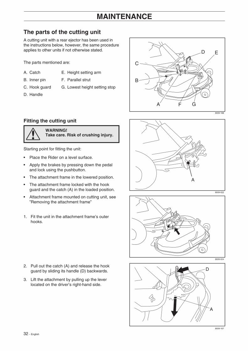
The parts of the cutting unitA cutting unit with a rear ejector has been used inthe instructions below, however, the same procedureapplies to other units if not otherwise stated.
The parts mentioned are:
A. Catch E. Height setting arm
B. Inner pin F. Parallel strut
C. Hook guard G. Lowest height setting stop
D. Handle
2. Pull out the catch (A) and release the hookguard by sliding its handle (D) backwards.
3. Lift the attachment by pulling up the leverlocated on the driver’s right-hand side.
Fitting the cutting unit
Starting point for fitting the unit:
• Place the Rider on a level surface.
• Apply the brakes by pressing down the pedaland lock using the pushbutton.
• The attachment frame in the lowered position.
• The attachment frame locked with the hookguard and the catch (A) in the loaded position.
• Attachment frame mounted on cutting unit, see”Removing the attachment frame”
1. Fit the unit in the attachment frame’s outerhooks.
WARNING!Take care. Risk of crushing injury.
A
A
D
A
B
C
D
F
E
G
8009-188
8009-022
8009-024
8009-167
English – 33
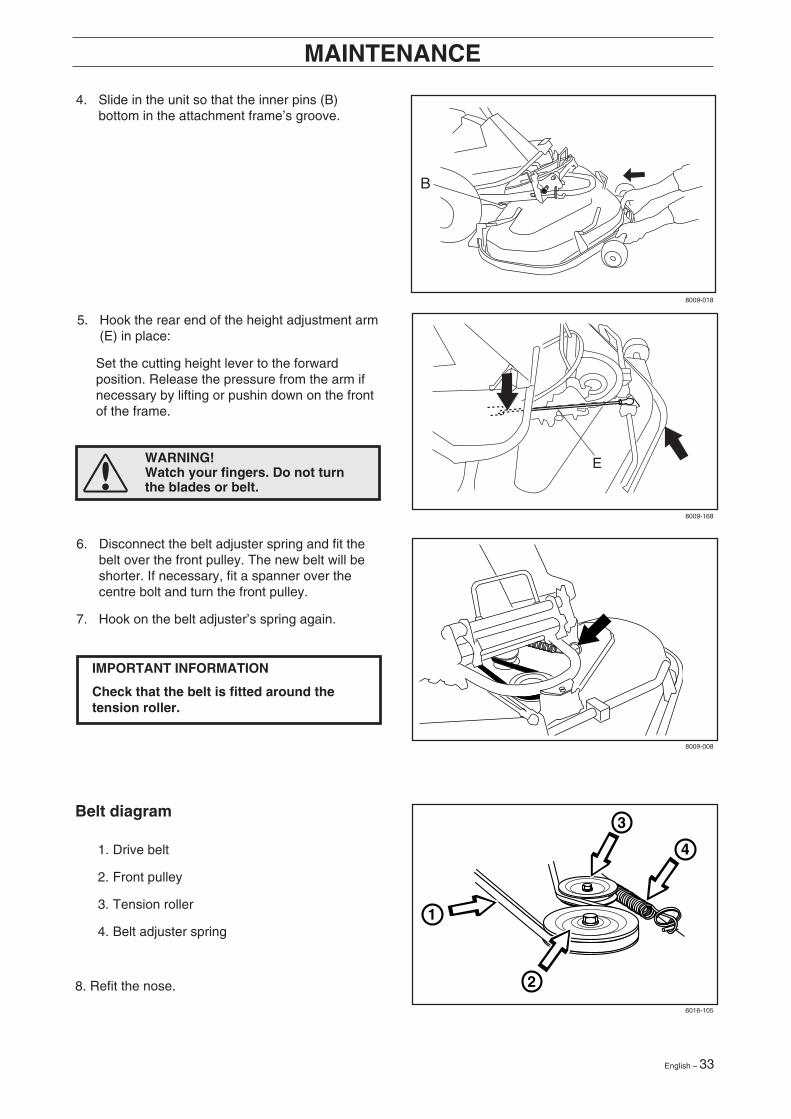
5. Hook the rear end of the height adjustment arm(E) in place:
Set the cutting height lever to the forwardposition. Release the pressure from the arm ifnecessary by lifting or pushin down on the frontof the frame.
6. Disconnect the belt adjuster spring and fit thebelt over the front pulley. The new belt will beshorter. If necessary, fit a spanner over thecentre bolt and turn the front pulley.
7. Hook on the belt adjuster’s spring again.
MAINTENANCE
4. Slide in the unit so that the inner pins (B)bottom in the attachment frame’s groove.
IMPORTANT INFORMATION
Check that the belt is fitted around thetension roller.
Belt diagram
1. Drive belt
2. Front pulley
3. Tension roller
4. Belt adjuster spring
8. Refit the nose.
WARNING!Watch your fingers. Do not turnthe blades or belt.
2
3
4
1
E
8009-018
8009-168
8009-008
6016-105
34 – English
MAINTENANCE
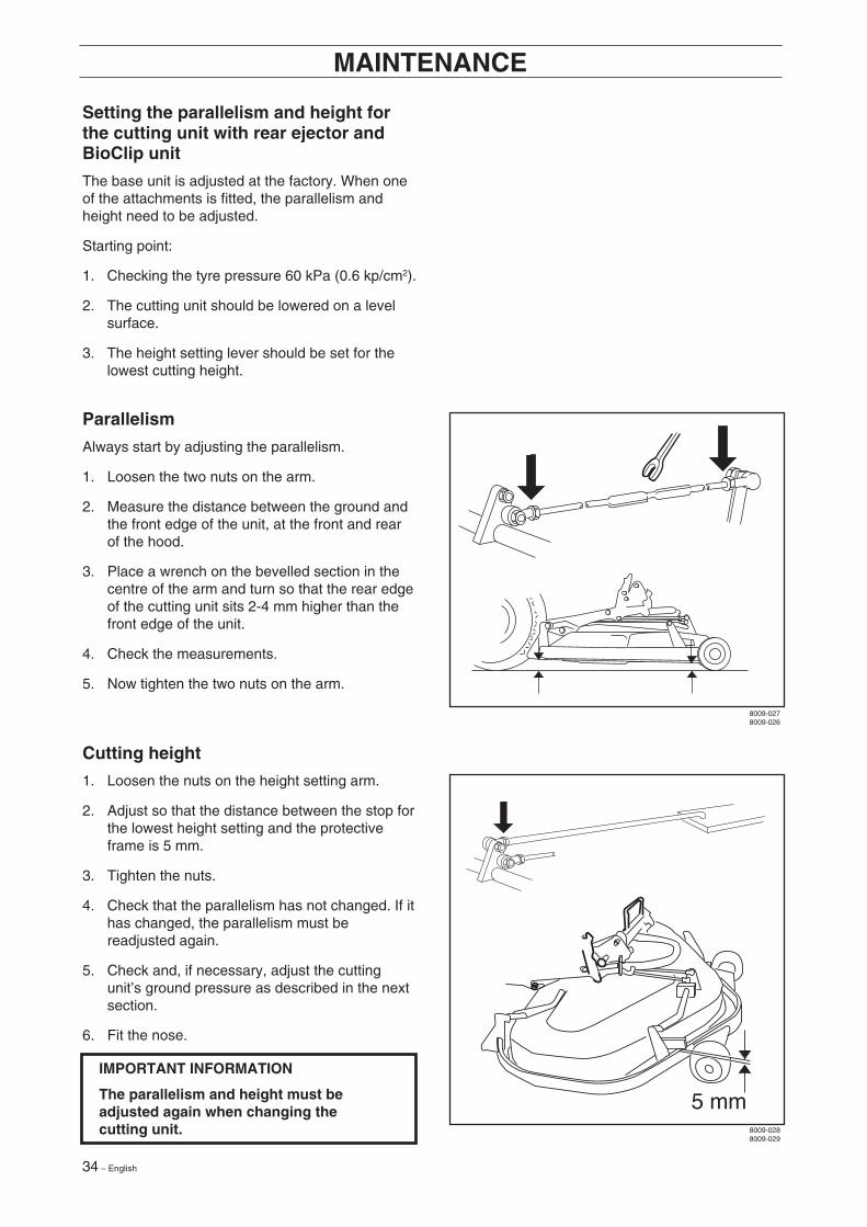
Setting the parallelism and height forthe cutting unit with rear ejector andBioClip unit
The base unit is adjusted at the factory. When oneof the attachments is fitted, the parallelism andheight need to be adjusted.
Starting point:
1. Checking the tyre pressure 60 kPa (0.6 kp/cm2).
2. The cutting unit should be lowered on a levelsurface.
3. The height setting lever should be set for thelowest cutting height.
IMPORTANT INFORMATION
The parallelism and height must beadjusted again when changing thecutting unit.
Parallelism
Always start by adjusting the parallelism.
1. Loosen the two nuts on the arm.
2. Measure the distance between the ground andthe front edge of the unit, at the front and rearof the hood.
3. Place a wrench on the bevelled section in thecentre of the arm and turn so that the rear edgeof the cutting unit sits 2-4 mm higher than thefront edge of the unit.
4. Check the measurements.
5. Now tighten the two nuts on the arm.
Cutting height
1. Loosen the nuts on the height setting arm.
2. Adjust so that the distance between the stop forthe lowest height setting and the protectiveframe is 5 mm.
3. Tighten the nuts.
4. Check that the parallelism has not changed. If ithas changed, the parallelism must bereadjusted again.
5. Check and, if necessary, adjust the cuttingunit’s ground pressure as described in the nextsection.
6. Fit the nose.
8009-0278009-026
8009-0288009-029

English – 35
MAINTENANCE
Checking and adjustment of the cuttingunit’s ground pressure
To achieve the best cutting results the cutting unitshould follow the underlying surface without pres-sing too hard against it.The pressure is adjusted with a screw on each sideof the machine.
Adjusting of the cutting unit’s ground pressure isconducted as follows:
1. Place a set of bathroom scales under the cuttingunit’s frame (front edge) so that it rests on thescales. If necessary a block can be placedbetween the frame and scales so that the sup-port wheels do not bear any weight.
2. Adjust the unit’s ground pressure by screwing inor out the adjusting screws located behind thefront wheels on both sides.
The ground pressure should be between 12 and15 kg and the springs evenly tensioned.
Replacing the break-pin (BioClip 103)
The blades are fitted with a break-pin to protect theBioClip unit and its drive when colliding withobstacles. A domed, spring friction washer is fittedto each blade bolt. The washer must always bereplaced with a new washer when replacing thebreak-pin. Otherwise the break-pin can breakcausing the blades to collide.
Only use original spare parts. A set containing ablade, break-pin and friction washer can bepurchased from your dealer.
1. Put the unit in the service position, see ”Placingin the service position”.
2. Remove the blade (2A) by removing the bladebolt with washer and friction washer (2B).
3. Remove the remains of the broken break-pin(3).
4. Make sure the contact surfaces (4) on the bladeand the blade mounting are free from metal.Clean if necessary.
5. Fit one new break-pin (5) in the blademounting.
6. Fit the blade (6), make sure it is fitted asillustrated.
7. Fit a new friction washer (7) with the concaveface turned towards the blade.
8. Fit the blade bolt with washer (8). Tighteningtorque 45-50 Nm (4,5-5 kpm)
2B
3
4
4
6
2A
7
8
5
6016-107
6008-222
8009-137
36 – English
MAINTENANCE
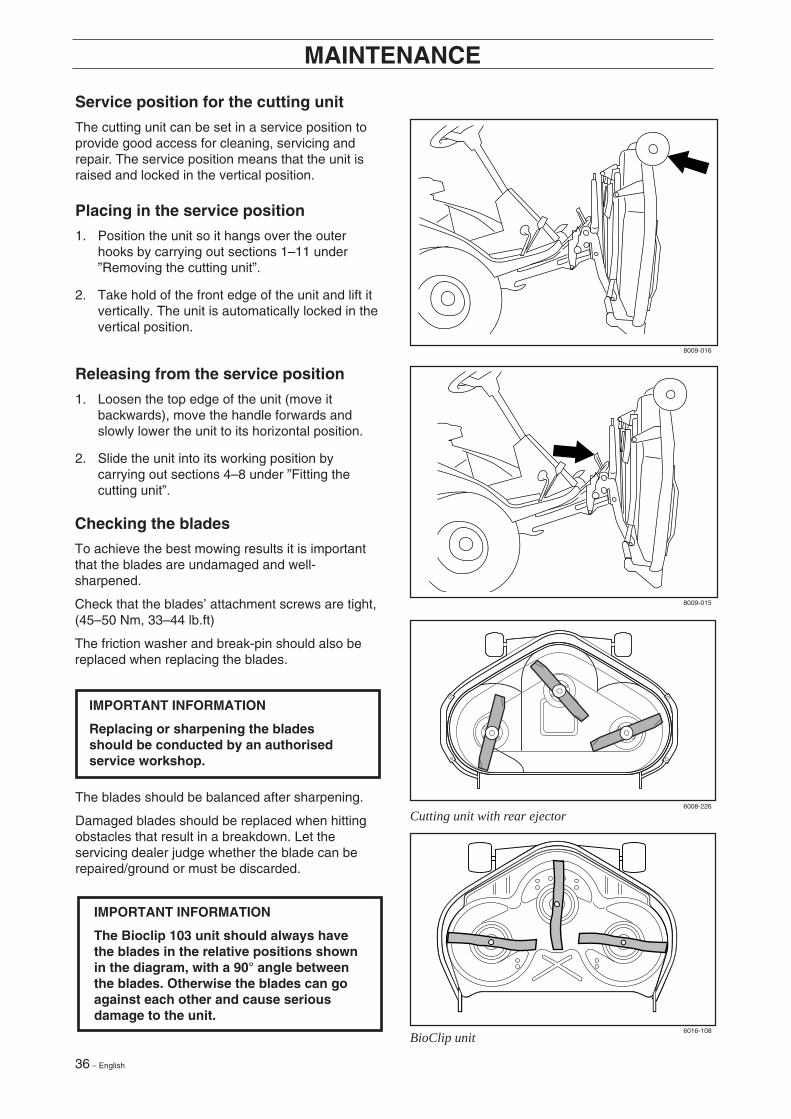
Service position for the cutting unit
The cutting unit can be set in a service position toprovide good access for cleaning, servicing andrepair. The service position means that the unit israised and locked in the vertical position.
Placing in the service position
1. Position the unit so it hangs over the outerhooks by carrying out sections 1–11 under”Removing the cutting unit”.
2. Take hold of the front edge of the unit and lift itvertically. The unit is automatically locked in thevertical position.
Releasing from the service position
1. Loosen the top edge of the unit (move itbackwards), move the handle forwards andslowly lower the unit to its horizontal position.
2. Slide the unit into its working position bycarrying out sections 4–8 under ”Fitting thecutting unit”.
IMPORTANT INFORMATION
The Bioclip 103 unit should always havethe blades in the relative positions shownin the diagram, with a 90° angle betweenthe blades. Otherwise the blades can goagainst each other and cause seriousdamage to the unit.
IMPORTANT INFORMATION
Replacing or sharpening the bladesshould be conducted by an authorisedservice workshop.
Checking the blades
To achieve the best mowing results it is importantthat the blades are undamaged and well-sharpened.
Check that the blades’ attachment screws are tight,(45–50 Nm, 33–44 lb.ft)
The friction washer and break-pin should also bereplaced when replacing the blades.
The blades should be balanced after sharpening.
Damaged blades should be replaced when hittingobstacles that result in a breakdown. Let theservicing dealer judge whether the blade can berepaired/ground or must be discarded.
8009-016
8009-015
6008-226
6016-108
Cutting unit with rear ejector
BioClip unit

English – 37
Dismantling the cutting unit
MAINTENANCE
8. Hang the belt around the handle.
5. Remove the belt adjuster’s spring.
6. Take the belt off the front pulley.
7. Hook on the belt adjuster’s spring again.
3. Lift up the unit using the lifting lever.
4. Remove the nose.
WARNING!Take care. Risk of crushing injury
1. Place the Rider on a level surface.
2. Apply the brakes by pressing down the pedaland lock using the pushbutton.
8009-001
8009-007
8009-008
8009-009
38 – English
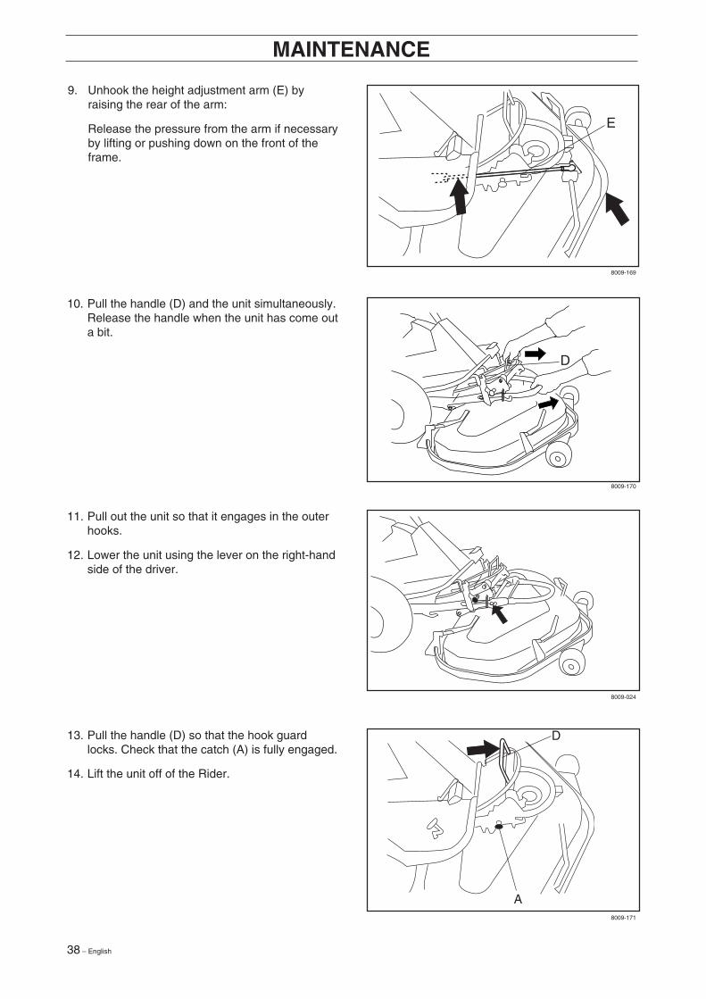
9. Unhook the height adjustment arm (E) byraising the rear of the arm:
Release the pressure from the arm if necessaryby lifting or pushing down on the front of theframe.
MAINTENANCE
13. Pull the handle (D) so that the hook guardlocks. Check that the catch (A) is fully engaged.
14. Lift the unit off of the Rider.
11. Pull out the unit so that it engages in the outerhooks.
12. Lower the unit using the lever on the right-handside of the driver.
10. Pull the handle (D) and the unit simultaneously.Release the handle when the unit has come outa bit.
8009-169
8009-170
8009-024
8009-171
English – 39
MAINTENANCE
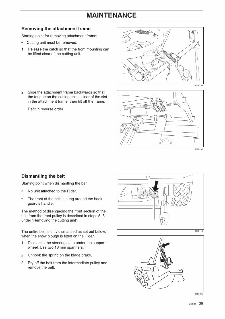
Dismantling the belt
Starting point when dismantling the belt:
• No unit attached to the Rider.
• The front of the belt is hung around the hookguard’s handle.
The method of disengaging the front section of thebelt from the front pulley is described in steps 5–8under ”Removing the cutting unit”.
The entire belt is only dismantled as set out below,when the snow plough is fitted on the Rider.
1. Dismantle the steering plate under the supportwheel. Use two 13 mm spanners.
2. Unhook the spring on the blade brake.
3. Pry off the belt from the intermediate pulley andremove the belt.
Removing the attachment frame
Starting point for removing attachment frame:
• Cutting unit must be removed.
1. Release the catch so that the front mounting canbe lifted clear of the cutting unit.
2. Slide the attachment frame backwards so thatthe tongue on the cutting unit is clear of the slotin the attachment frame, then lift off the frame.
Refit in reverse order.
8009-184
8009-185
6016-114
8009-005
40 – English
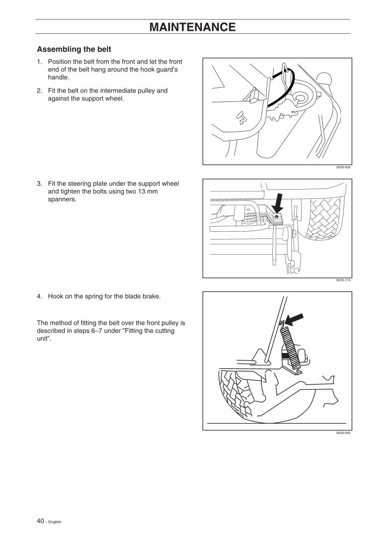
Assembling the belt
1. Position the belt from the front and let the frontend of the belt hang around the hook guard’shandle.
2. Fit the belt on the intermediate pulley andagainst the support wheel.
MAINTENANCE
4. Hook on the spring for the blade brake.
The method of fitting the belt over the front pulley isdescribed in steps 6–7 under ”Fitting the cuttingunit”.
3. Fit the steering plate under the support wheeland tighten the bolts using two 13 mmspanners.
8009-009
6016-114
8009-005
English – 41
MAINTENANCE
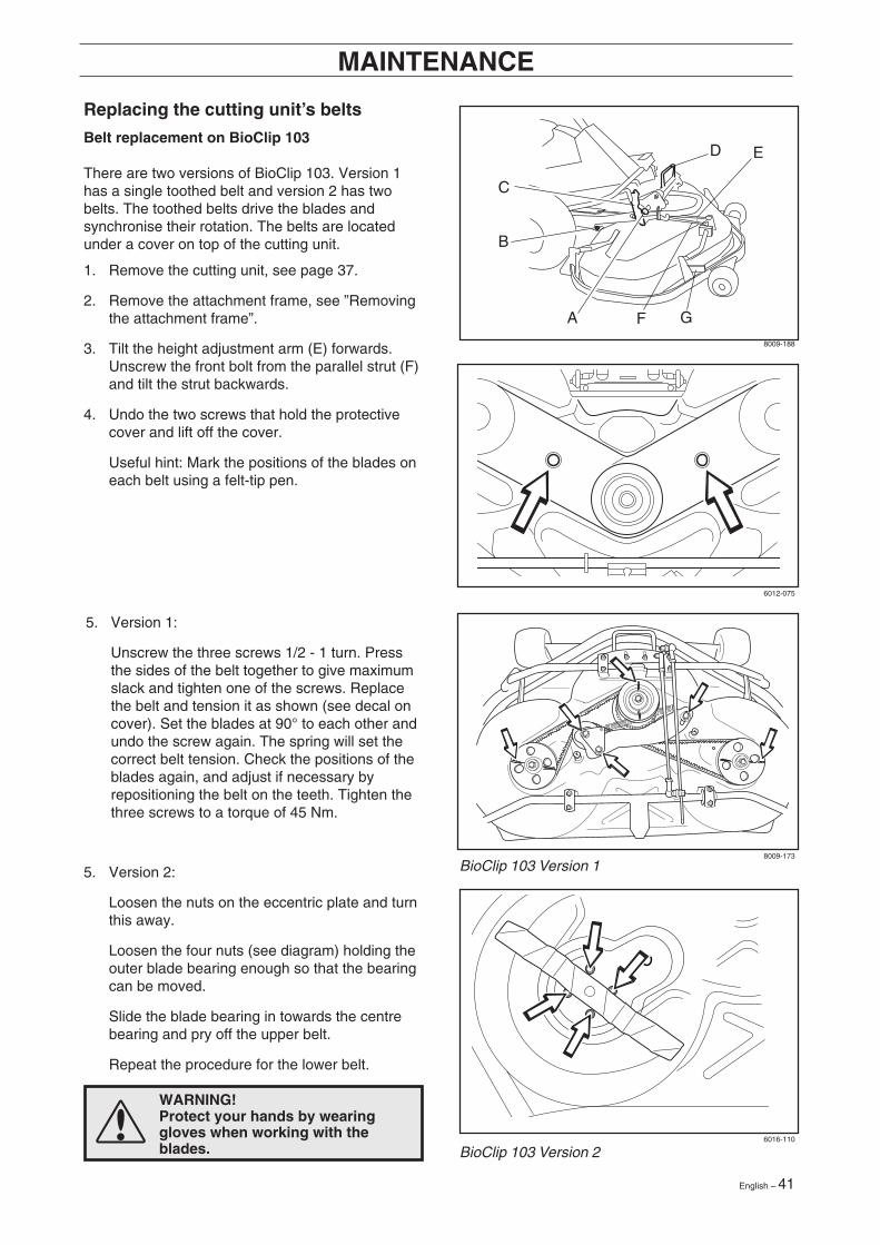
Replacing the cutting unit’s belts
Belt replacement on BioClip 103
There are two versions of BioClip 103. Version 1has a single toothed belt and version 2 has twobelts. The toothed belts drive the blades andsynchronise their rotation. The belts are locatedunder a cover on top of the cutting unit.
1. Remove the cutting unit, see page 37.
2. Remove the attachment frame, see ”Removingthe attachment frame”.
3. Tilt the height adjustment arm (E) forwards.Unscrew the front bolt from the parallel strut (F)and tilt the strut backwards.
4. Undo the two screws that hold the protectivecover and lift off the cover.
Useful hint: Mark the positions of the blades oneach belt using a felt-tip pen.
5. Version 2:
Loosen the nuts on the eccentric plate and turnthis away.
Loosen the four nuts (see diagram) holding theouter blade bearing enough so that the bearingcan be moved.
Slide the blade bearing in towards the centrebearing and pry off the upper belt.
Repeat the procedure for the lower belt.
WARNING!Protect your hands by wearinggloves when working with theblades.
A
B
C
D
F
E
G
8009-188
6012-075
8009-173
6016-110
BioClip 103 Version 1
BioClip 103 Version 2
5. Version 1:
Unscrew the three screws 1/2 - 1 turn. Pressthe sides of the belt together to give maximumslack and tighten one of the screws. Replacethe belt and tension it as shown (see decal oncover). Set the blades at 90° to each other andundo the screw again. The spring will set thecorrect belt tension. Check the positions of theblades again, and adjust if necessary byrepositioning the belt on the teeth. Tighten thethree screws to a torque of 45 Nm.

42 – English
MAINTENANCE
Belt change on cutting unit with side or rearejection and Combi unit
On these cutting units with ”collision-proof” blades,the blades are driven by one V-belt. Do as follows tochange the V-belt:
1. Loosen the unit frame (1), the bolt on theparallelism arm (2) and the two bolts on thehood (3). Lift off the cutting unit’s hood.
2. Loosen the spring that tensions the V-belt andpry off the belt.
Reverse the procedure to fit the new belt.
6. Version 2:
Assembly: First fit the lower belt and then theupper belt.
Ensure the blades are positioned as set out inthe diagram, at 90 degrees to each other,otherwise the belts must be adjusted. When theblade bearings are loose the belts can bemoved around to the next tooth.
Tighten the nuts enough so that the bearingsrest against the cutting hood but still can bemoved.
Tension the belt by turning the eccentric adjusteron top of the cutting hood. Tighten the nut.
Tighten all nuts on the blade bearings.
7. Version 2:
When the belt can be moved 7 mm inwards usinga force of 10 N the belt is adjusted correctly.
8. Version 1 and 2:
Fit the cover over the belts and refit the parallelstrut and attachment frame.
1
2
3
3
6016-111
6012-079
6016-113
6012-080
IMPORTANT INFORMATION
On BioClip 103 units the belts must be setat 90° to each other. In all other cases theblades can collide and cause seriousdamage to the cutting unit.
English – 43
8009-289
6017-108
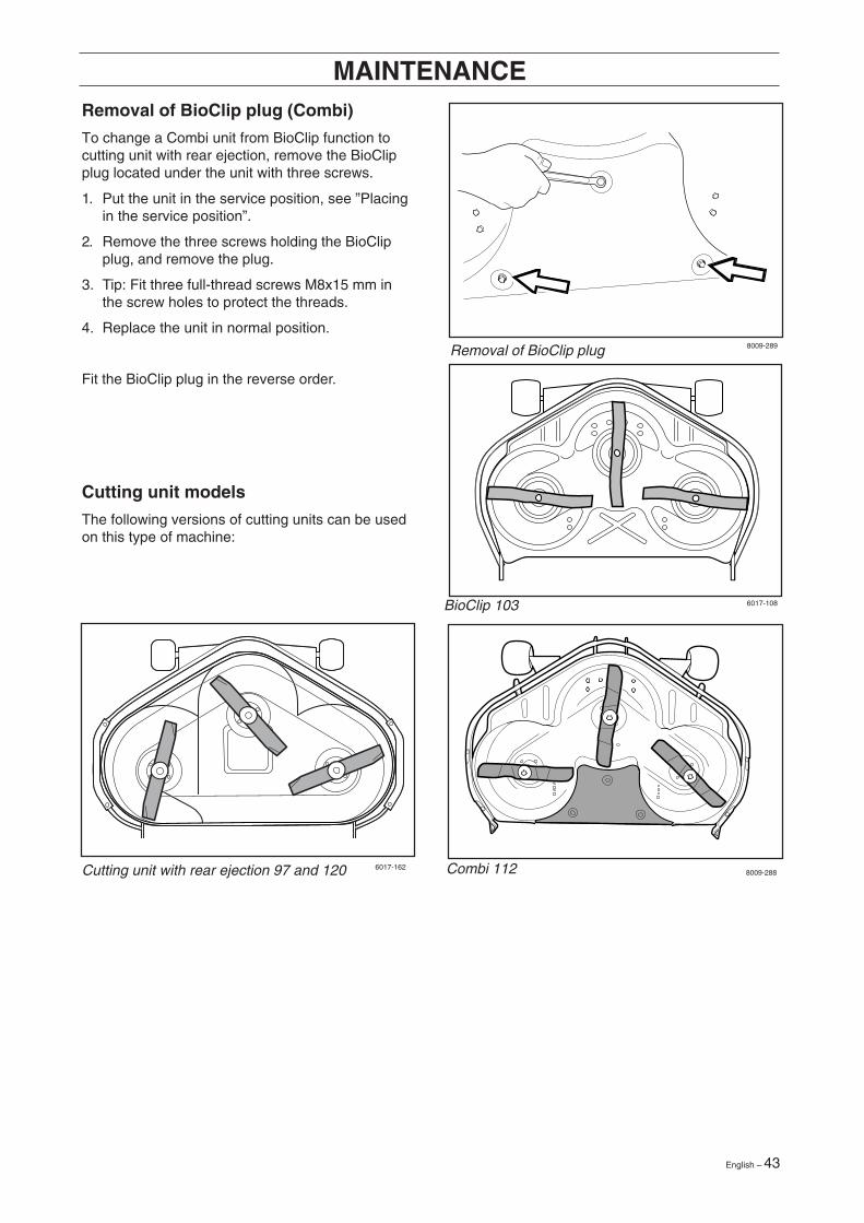
Combi 112 8009-2886017-162
BioClip 103
MAINTENANCERemoval of BioClip plug (Combi)
To change a Combi unit from BioClip function tocutting unit with rear ejection, remove the BioClipplug located under the unit with three screws.
1. Put the unit in the service position, see ”Placingin the service position”.
2. Remove the three screws holding the BioClipplug, and remove the plug.
3. Tip: Fit three full-thread screws M8x15 mm inthe screw holes to protect the threads.
4. Replace the unit in normal position.
Fit the BioClip plug in the reverse order.
Cutting unit models
The following versions of cutting units can be usedon this type of machine:
Cutting unit with rear ejection 97 and 120
Removal of BioClip plug
44 – English
LUBRICATION
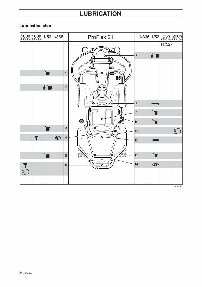
Lubrication chart
ProFlex 21 1/3651/365(365/365)(365/365)
1/52
(1/52)
1/52 200h 25h(365/365)500h
(365/365)100h
1
2
7
8
9
10
11
12
13
14
3
4
5
6
8009-163
English – 45
LUBRICATION
General
Remove the ignition key to prevent accidental movement during lubrication.
If lubricating with an oil can, fill the can with engine oil.
If lubricating with grease, use grease 503 98 96-01 or a similar chassis grease or bearing grease with goodcorrosion resistance, unless otherwise specified.
If the Rider is used daily it should be lubricated twice a week.
Wipe off excess lubricant after lubrication.
It is important that lubricant does not get onto the drive surfaces of the belts or pulleys. If this happens, try toclean it off with white spirit. If the belt continues to slip it must be replaced. Do not use petrol or otherpetroleum products to clean V-belts.
Lubricating wires
Lubricate both ends of the wires, moving the controls through their full travel range while doing so. Refit therubber protectors over the wires after lubrication. Wires with a casing will seize up unless lubricatedregularly. If a wire seizes it can cause operating problems, such as difficulty disengaging the differential lock.
If a wire does seize up, remove it and hang it up vertically. Lubricate with light engine oil until the oil starts todrip from the lower end. Useful hint: Fill a small plastic bag with oil, tape it tightly around the wire casing andhang the wire vertically from the bag overnight. If this does not free up the wire then it must be replaced.
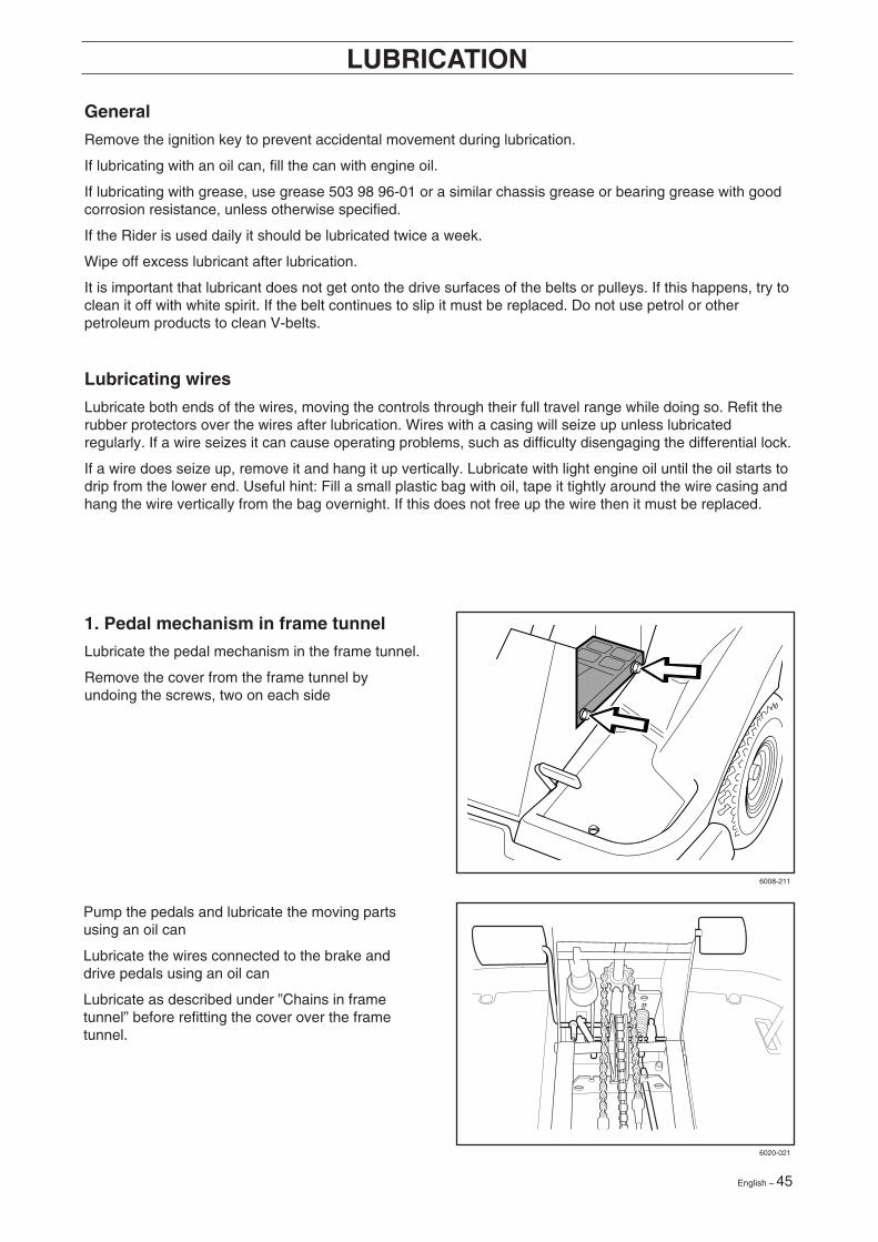
1. Pedal mechanism in frame tunnel
Lubricate the pedal mechanism in the frame tunnel.
Remove the cover from the frame tunnel byundoing the screws, two on each side
Pump the pedals and lubricate the moving partsusing an oil can
Lubricate the wires connected to the brake anddrive pedals using an oil can
Lubricate as described under ”Chains in frametunnel” before refitting the cover over the frametunnel.
6008-211
6020-021
46 – English
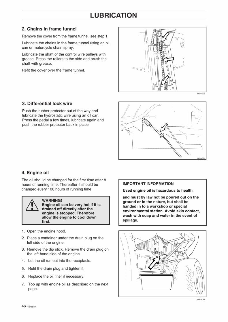
2. Chains in frame tunnel
Remove the cover from the frame tunnel, see step 1.
Lubricate the chains in the frame tunnel using an oilcan or motorcycle chain spray.
Lubricate the shaft of the control wire pulleys withgrease. Press the rollers to the side and brush theshaft with grease.
Refit the cover over the frame tunnel.
LUBRICATION
3. Differential lock wire
Push the rubber protector out of the way andlubricate the hydrostatic wire using an oil can.Press the pedal a few times, lubricate again andpush the rubber protector back in place.
4. Engine oil
The oil should be changed for the first time after 8hours of running time. Thereafter it should bechanged every 100 hours of running time.
WARNING!Engine oil can be very hot if it isdrained off directly after theengine is stopped. Thereforeallow the engine to cool downfirst.
1. Open the engine hood.
2. Place a container under the drain plug on theleft side of the engine.
3. Remove the dip stick. Remove the drain plug onthe left-hand side of the engine.
4. Let the oil run out into the receptacle.
5. Refit the drain plug and tighten it.
6. Replace the oil filter if necessary.
7. Top up with engine oil as described on the nextpage.
IMPORTANT INFORMATION
Used engine oil is hazardous to health
and must by law not be poured out on theground or in the nature, but shall behanded in to a workshop or specialenvironmental station. Avoid skin contact,wash with soap and water in the event ofspillage.
6020-022
6020-023
8009-160
English – 47
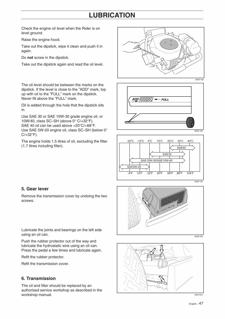
Check the engine oil level when the Rider is onlevel ground.
Raise the engine hood.
Take out the dipstick, wipe it clean and push it inagain.
Do not screw in the dipstick.
Take out the dipstick again and read the oil level.
LUBRICATION
The oil level should be between the marks on thedipstick. If the level is close to the ”ADD” mark, topup with oil to the ”FULL” mark on the dipstick.Never fill above the ”FULL” mark.
Oil is added through the hole that the dipstick sitsin.
Use SAE 30 or SAE 10W-30 grade engine oil, or10W/40, class SC–SH (above 0° C/+32°F).SAE 40 oil can be used above +20°C/+68°F.Use SAE 5W-20 engine oil, class SC–SH (below 0°C/+32°F).
The engine holds 1.5 litres of oil, excluding the filter(1.7 litres including filter).
5. Gear lever
Remove the transmission cover by undoing the twoscrews.
Lubricate the joints and bearings on the left sideusing an oil can.
Push the rubber protector out of the way andlubricate the hydrostatic wire using an oil can.Press the pedal a few times and lubricate again.
Refit the rubber protector.
Refit the transmission cover.
6. Transmission
The oil and filter should be replaced by anauthorised service workshop as described in theworkshop manual.
ADD FULL
ADD FULL
-20 C
-4 F 14 F 32 F 50 F 68 F 86 F 104 F
SAE30
SAE40
SAE10W-30/SAE10W-40
-10 C 0 C 10 C 20 C 30 C 40 C
SAE5W-20
8009-158
8009-159
8009-140
6008-209
6020-024
48 – English
LUBRICATION
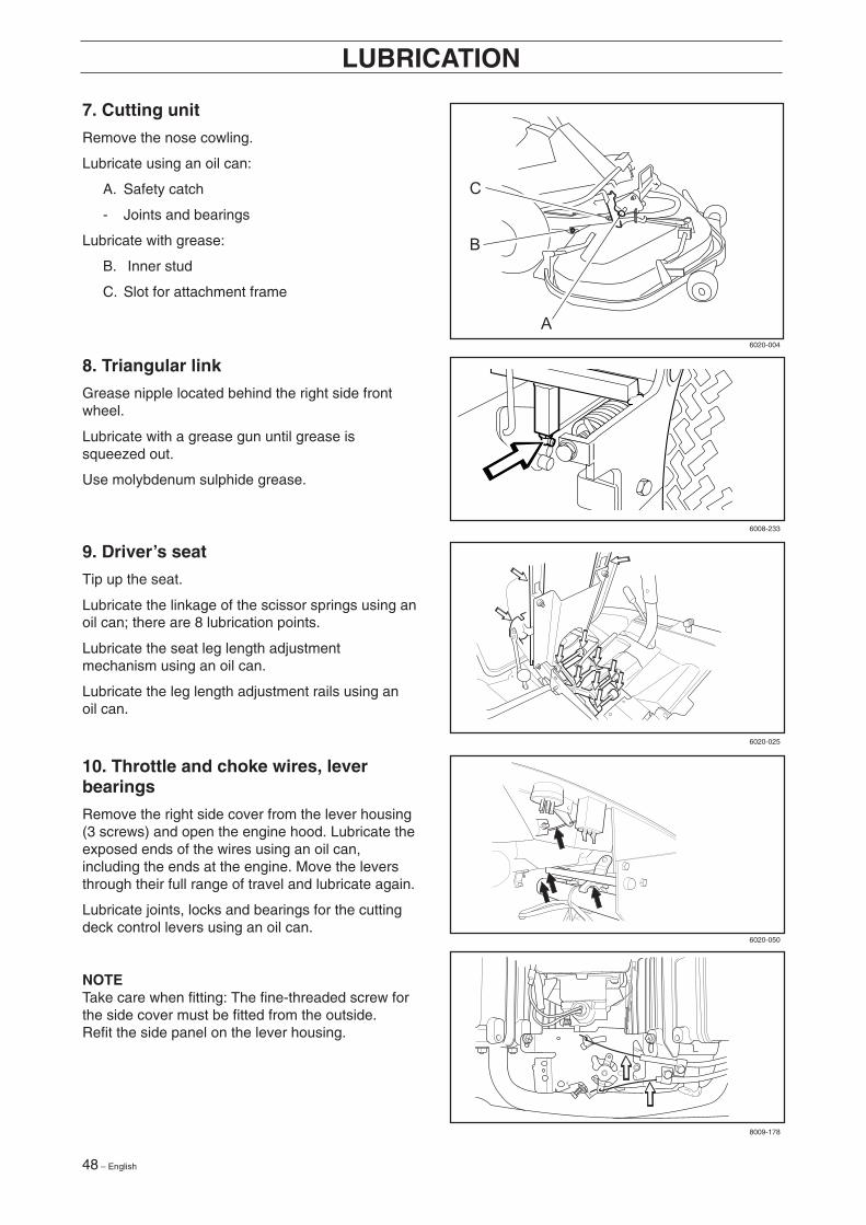
7. Cutting unit
Remove the nose cowling.
Lubricate using an oil can:
A. Safety catch
- Joints and bearings
Lubricate with grease:
B. Inner stud
C. Slot for attachment frame
8. Triangular link
Grease nipple located behind the right side frontwheel.
Lubricate with a grease gun until grease issqueezed out.
Use molybdenum sulphide grease.
9. Driver’s seat
Tip up the seat.
Lubricate the linkage of the scissor springs using anoil can; there are 8 lubrication points.
Lubricate the seat leg length adjustmentmechanism using an oil can.
Lubricate the leg length adjustment rails using anoil can.
10. Throttle and choke wires, leverbearings
Remove the right side cover from the lever housing(3 screws) and open the engine hood. Lubricate theexposed ends of the wires using an oil can,including the ends at the engine. Move the leversthrough their full range of travel and lubricate again.
Lubricate joints, locks and bearings for the cuttingdeck control levers using an oil can.
NOTETake care when fitting: The fine-threaded screw forthe side cover must be fitted from the outside.Refit the side panel on the lever housing.
6020-004
6008-233
6020-025
6020-050
8009-178
English – 49
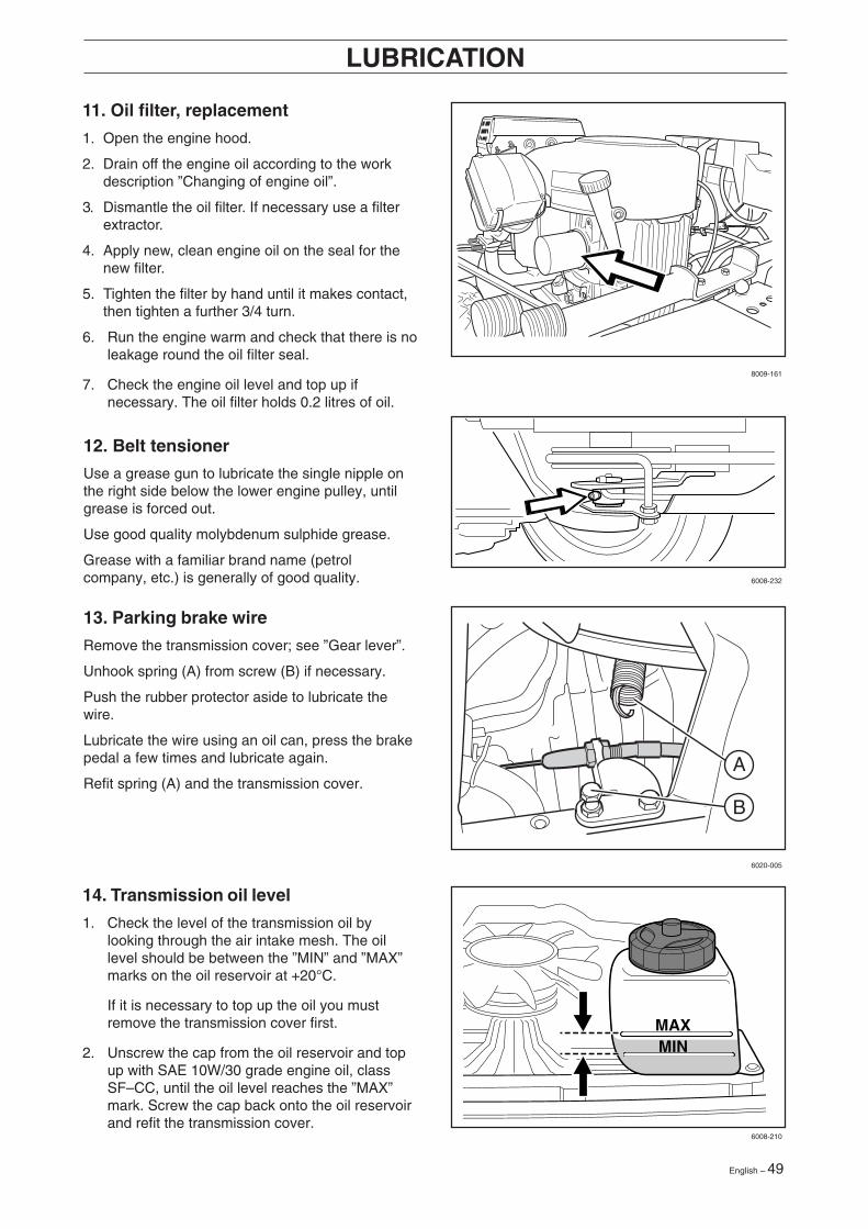
11. Oil filter, replacement
1. Open the engine hood.
2. Drain off the engine oil according to the workdescription ”Changing of engine oil”.
3. Dismantle the oil filter. If necessary use a filterextractor.
4. Apply new, clean engine oil on the seal for thenew filter.
5. Tighten the filter by hand until it makes contact,then tighten a further 3/4 turn.
6. Run the engine warm and check that there is noleakage round the oil filter seal.
7. Check the engine oil level and top up ifnecessary. The oil filter holds 0.2 litres of oil.
LUBRICATION
12. Belt tensioner
Use a grease gun to lubricate the single nipple onthe right side below the lower engine pulley, untilgrease is forced out.
Use good quality molybdenum sulphide grease.
Grease with a familiar brand name (petrolcompany, etc.) is generally of good quality.
13. Parking brake wire
Remove the transmission cover; see ”Gear lever”.
Unhook spring (A) from screw (B) if necessary.
Push the rubber protector aside to lubricate thewire.
Lubricate the wire using an oil can, press the brakepedal a few times and lubricate again.
Refit spring (A) and the transmission cover.
14. Transmission oil level
1. Check the level of the transmission oil bylooking through the air intake mesh. The oillevel should be between the ”MIN” and ”MAX”marks on the oil reservoir at +20°C.
If it is necessary to top up the oil you mustremove the transmission cover first.
2. Unscrew the cap from the oil reservoir and topup with SAE 10W/30 grade engine oil, classSF–CC, until the oil level reaches the ”MAX”mark. Screw the cap back onto the oil reservoirand refit the transmission cover.
B
A
8009-161
6008-232
6020-005
6008-210

50 – English
TROUBLE SHOOTING SCHEDULE
Problem Procedure
Engine will not start. • Fuel tank empty.• Plugs defective.• Plug connections defective.• Dirt in carburettor or fuel pipe.
Starter does not pull round engine. • Battery flat.• Bad contact between cables and battery terminals.• Lift lever for cutting unit in wrong position.• Main fuse blown. The fuse is located in front of the
battery under the battery cover.• Ignition lock faulty.• Brake not engaged• Hydrostat pedals not in the neutral position
Engine does not run smoothly. • Plugs defective.• Carburettor incorrectly set.• Air filter clogged.• Fuel tank vent blocked.• Ignition setting defective.• Dirt in fuel pipe.• Choking or incorrectly adjusted throttle cable
Engine seems to have no power. • Air filter clogged.• Plug defective.• Dirt in carburettor or fuel pipe.• Carburettor incorrectly set.• Choking or incorrectly adjusted throttle cable
Engine overheats. • Engine overloaded.• Air intake or cooling flanges blocked.• Fan damaged.• Too little or no oil in engine.• Ignition defective.• Plugs defective.
Battery does not charge. • One or more cells in the battery faulty.• Bad contact between battery terminals and cables.
Machine vibrates. • Blades are loose.• Engine is loose.• Imbalance on one or more blades, resulting from
damage or inferior balancing after sharpening.
Uneven mowing. • Blades blunt.• Cutting unit set skew.• Long or wet grass.• Grass blockage under hood.• Different tyre pressures on right and left sides.• Over-speeding• Drive belts slipping.• The blade has a broken break-pin (BioClip)
English – 51
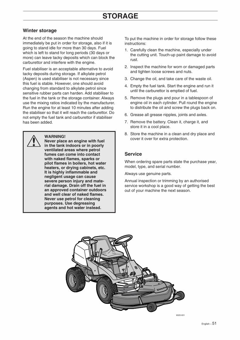
STORAGE
To put the machine in order for storage follow theseinstructions:
1. Carefully clean the machine, especially underthe cutting unit. Touch-up paint damage to avoidrust.
2. Inspect the machine for worn or damaged partsand tighten loose screws and nuts.
3. Change the oil, and take care of the waste oil.
4. Empty the fuel tank. Start the engine and run ituntil the carburettor is emptied of fuel.
5. Remove the plugs and pour in a tablespoon ofengine oil in each cylinder. Pull round the engineto distribute the oil and screw the plugs back on.
6. Grease all grease nipples, joints and axles.
7. Remove the battery. Clean it, charge it, andstore it in a cool place.
8. Store the machine in a clean and dry place andcover it over for extra protection.
Service
When ordering spare parts state the purchase year,model, type, and serial number.
Always use genuine parts.
Annual inspection or trimming by an authorisedservice workshop is a good way of getting the bestout of your machine the next season.
Winter storage
At the end of the season the machine shouldimmediately be put in order for storage, also if it isgoing to stand idle for more than 30 days. Fuelwhich is left to stand for long periods (30 days ormore) can leave tacky deposits which can block thecarburettor and interfere with the engine.
Fuel stabiliser is an acceptable alternative to avoidtacky deposits during storage. If alkylate petrol(Aspen) is used stabiliser is not necessary sincethis fuel is stable. However, one should avoidchanging from standard to alkylate petrol sincesensitive rubber parts can harden. Add stabiliser tothe fuel in the tank or the storage container. Alwaysuse the mixing ratios indicated by the manufacturer.Run the engine for at least 10 minutes after addingthe stabiliser so that it will reach the carburettor. Donot empty the fuel tank and carburettor if stabiliserhas been added.
WARNING!Never place an engine with fuelin the tank indoors or in poorlyventilated areas where petrolfumes can come into contactwith naked flames, sparks orpilot flames in boilers, hot waterheaters, or drying cabinets, etc.It is highly inflammable andnegligent usage can causesevere person injury and mate-rial damage. Drain off the fuel inan approved container outdoorsand well clear of naked flames.Never use petrol for cleaningpurposes. Use degreasingagents and hot water instead.
6020-001
52 – English
WIRING DIAGRAM
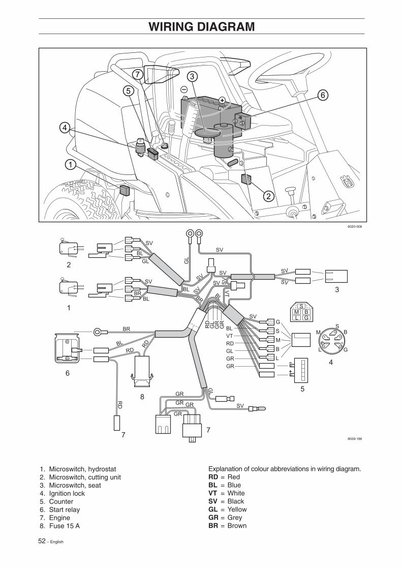
1. Microswitch, hydrostat2. Microswitch, cutting unit3. Microswitch, seat4. Ignition lock5. Counter6. Start relay7. Engine8. Fuse 15 A
Explanation of colour abbreviations in wiring diagram.RD = RedBL = BlueVT = WhiteSV = BlackGL = YellowGR = GreyBR = Brown
6020-006
8009-186
English – 53
TECHNICAL DATA
When the service life of this product has been served and it is no longer used it should bereturned to the dealer or to an applicable station for recycling.
Dimensions Rider ProFlex 21
Length, base machine 2 030 mmWidth, base machine 900 mmHeight 1 100 mmKerb weight, base machine 287 kg without cutting unitWheelbase 940 mmTrack 720 mmTyre size 18 x 7.50 x 8Tyre pressure, front & rear 60 kPa (0,6 kp/cm2)Max. gradient 15°
Engine
Manufacture KawasakiModel FH641V-AS50Power 15,5/21 kW/hkDisplacement 675 cm3 / 41.19 cu.in.Fuel min. 87 octane unleaded (max. methanol 5%,
max. ethanol 10%, max, MTBE 15%)Tank volume 10 litresOil SAE 30 or SAE 10W/30, SAE 10W/40 class SC-SHOljevolym 1.5 litres /1.6 US qtOil volume incl. filter 1.7 litres /1.8 US qtStart Electric starter
Noise emissions and cutting width Bio 103, Combi 112
Measured noise level 100 dB(A)Guaranteed noise level 100 dB(A)Cutting width 1030 - 1120 mm
Noise emissions and cutting width Rear 120
Measured noise level 101 dB(A)Guaranteed noise level 102 dB(A)Cutting width 1200 mm
Electrical system
Type 12 V, negative earthedBattery 12 V, 24 AhMain fuse Spade connector 15 ASpark plug NGK BPR4ES, electrode gap = 0.75 mm / 0.030"
Transmission
Manufacture Tuff Torq K 66Oil SAE 10W/30, class SF-CCOil capacity, total 2,5 litres
Rider ProFlex 21
54 – English
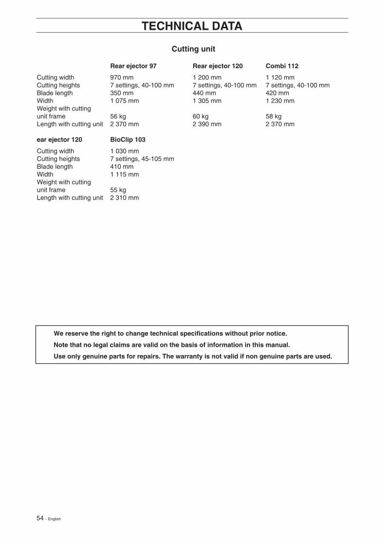
Cutting unit
Rear ejector 97 Rear ejector 120 Combi 112
Cutting width 970 mm 1 200 mm 1 120 mmCutting heights 7 settings, 40-100 mm 7 settings, 40-100 mm 7 settings, 40-100 mmBlade length 350 mm 440 mm 420 mmWidth 1 075 mm 1 305 mm 1 230 mmWeight with cuttingunit frame 56 kg 60 kg 58 kgLength with cutting unit 2 370 mm 2 390 mm 2 370 mm
ear ejector 120 BioClip 103
Cutting width 1 030 mmCutting heights 7 settings, 45-105 mmBlade length 410 mmWidth 1 115 mmWeight with cuttingunit frame 55 kgLength with cutting unit 2 310 mm
TECHNICAL DATA
We reserve the right to change technical specifications without prior notice.
Note that no legal claims are valid on the basis of information in this manual.
Use only genuine parts for repairs. The warranty is not valid if non genuine parts are used.

English – 55
EU-DECLARATION OF CONFORMITY
EU declaration of conformity (Only applies to Europe)
Husqvarna AB, SE-561 82 Huskvarna, Sweden, tel: +46-36-146500, declares under sole responsibility that theRider Husqvarna Rider ProFlex 21, from 2002’s serial numbers and onwards (the year is clearly stated in plain texton the rating plate with subsequent serial number), complies with the requirements of the COUNCIL’S DIRECTIVES:
- of June 22, 1998 ”relating to machinery” 98/37/EC, annex IIA.- of May 3, 1989 ”relating to electromagnetic compatibility” 89/336/EEC, and applicable supplements.- of May 8, 2000 ”relating to the emission of noise to surroundings” 2000/14/EC.Information regarding noise emissions and the mowing width, see the Technical Data.
The following harmonised standards have been applied: EN292-2, EN836.
The registered body 0404, SMP Svensk Maskinprovning AB, Fyrisborgsgatan 3, SE-754 50 Uppsala, Sweden hasissued the report with number 01/901/010 regarding the assessment of conformity according to annex VI to theCOUNCIL’S DIRECTIVE of May 8, 2000 ”relating to the emission of noise to surroundings” 2000/14/EC.
Huskvarna January 3, 2002
Roger Andersson, Development Manager/Garden Products
56 – English
SERVICEJOURNAL
Work done
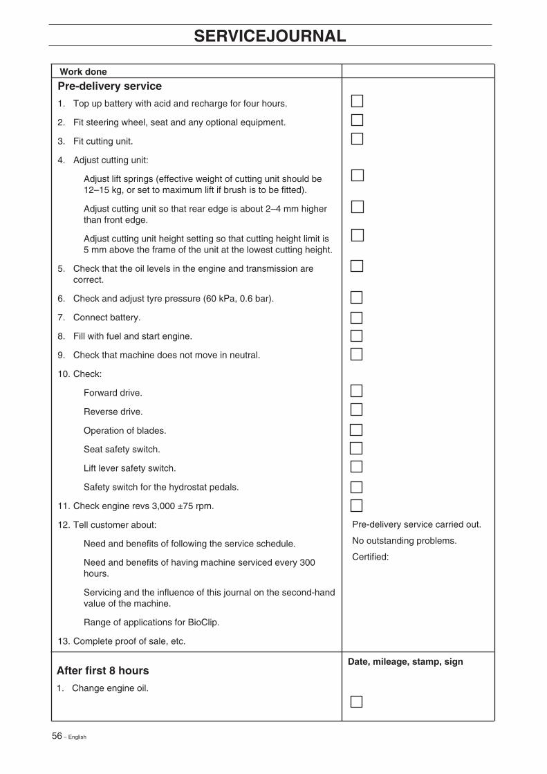
Pre-delivery service
1. Top up battery with acid and recharge for four hours.
2. Fit steering wheel, seat and any optional equipment.
3. Fit cutting unit.
4. Adjust cutting unit:
Adjust lift springs (effective weight of cutting unit should be12–15 kg, or set to maximum lift if brush is to be fitted).
Adjust cutting unit so that rear edge is about 2–4 mm higherthan front edge.
Adjust cutting unit height setting so that cutting height limit is5 mm above the frame of the unit at the lowest cutting height.
5. Check that the oil levels in the engine and transmission arecorrect.
6. Check and adjust tyre pressure (60 kPa, 0.6 bar).
7. Connect battery.
8. Fill with fuel and start engine.
9. Check that machine does not move in neutral.
10. Check:
Forward drive.
Reverse drive.
Operation of blades.
Seat safety switch.
Lift lever safety switch.
Safety switch for the hydrostat pedals.
11. Check engine revs 3,000 ±75 rpm.
12. Tell customer about:
Need and benefits of following the service schedule.
Need and benefits of having machine serviced every 300hours.
Servicing and the influence of this journal on the second-handvalue of the machine.
Range of applications for BioClip.
13. Complete proof of sale, etc.
Pre-delivery service carried out.
No outstanding problems.
Certified:
After first 8 hours
1. Change engine oil.
Date, mileage, stamp, sign
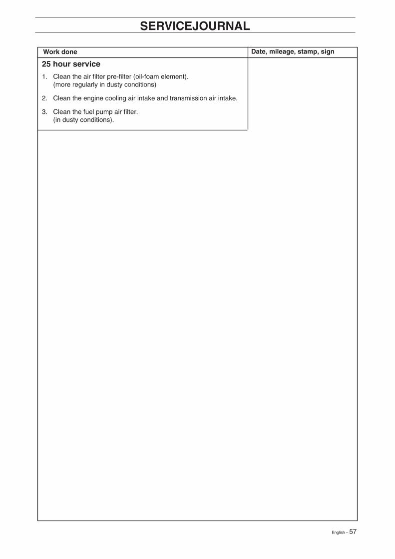
English – 57
SERVICEJOURNAL
Work done Date, mileage, stamp, sign
25 hour service
1. Clean the air filter pre-filter (oil-foam element).(more regularly in dusty conditions)
2. Clean the engine cooling air intake and transmission air intake.
3. Clean the fuel pump air filter.(in dusty conditions).
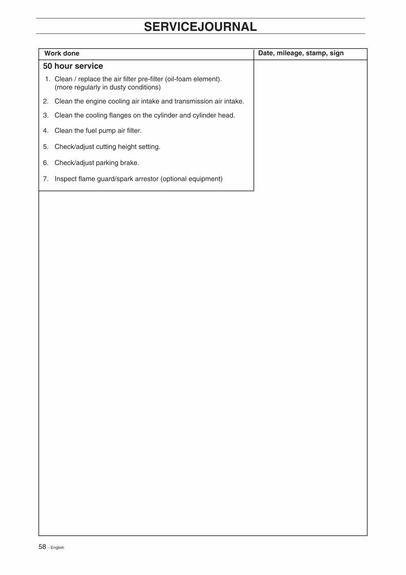
58 – English
SERVICEJOURNAL
Work done Date, mileage, stamp, sign
50 hour service
1. Clean / replace the air filter pre-filter (oil-foam element).(more regularly in dusty conditions)
2. Clean the engine cooling air intake and transmission air intake.
3. Clean the cooling flanges on the cylinder and cylinder head.
4. Clean the fuel pump air filter.
5. Check/adjust cutting height setting.
6. Check/adjust parking brake.
7. Inspect flame guard/spark arrestor (optional equipment)
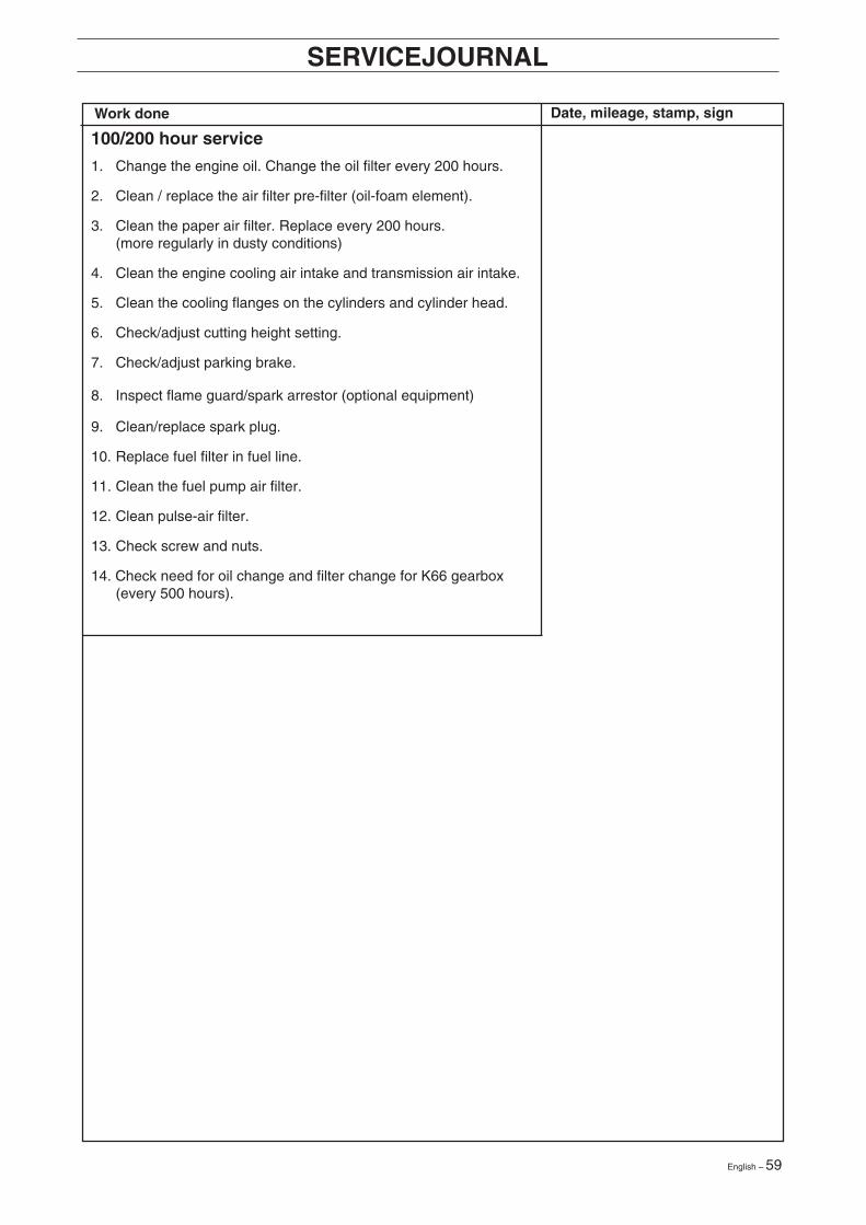
English – 59
SERVICEJOURNAL
Work done Date, mileage, stamp, sign
100/200 hour service
1. Change the engine oil. Change the oil filter every 200 hours.
2. Clean / replace the air filter pre-filter (oil-foam element).
3. Clean the paper air filter. Replace every 200 hours.(more regularly in dusty conditions)
4. Clean the engine cooling air intake and transmission air intake.
5. Clean the cooling flanges on the cylinders and cylinder head.
6. Check/adjust cutting height setting.
7. Check/adjust parking brake.
8. Inspect flame guard/spark arrestor (optional equipment)
9. Clean/replace spark plug.
10. Replace fuel filter in fuel line.
11. Clean the fuel pump air filter.
12. Clean pulse-air filter.
13. Check screw and nuts.
14. Check need for oil change and filter change for K66 gearbox(every 500 hours).
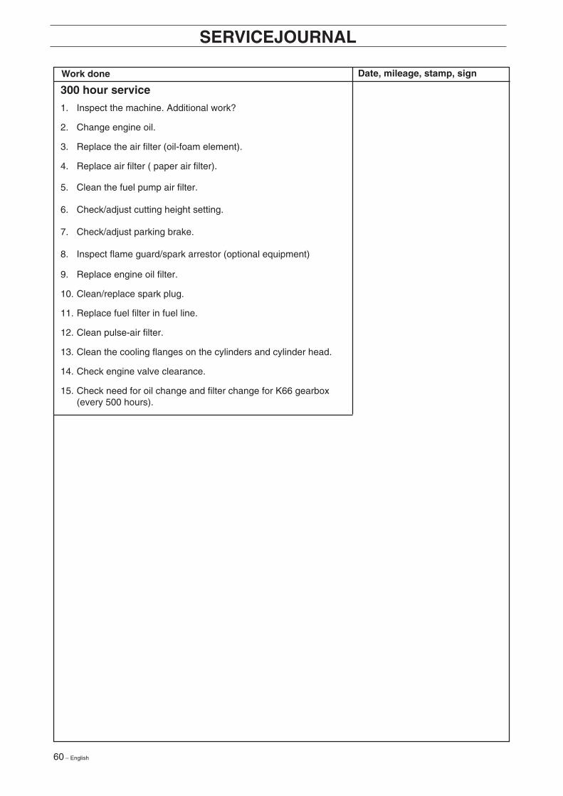
60 – English
SERVICEJOURNAL
Work done Date, mileage, stamp, sign
300 hour service
1. Inspect the machine. Additional work?
2. Change engine oil.
3. Replace the air filter (oil-foam element).
4. Replace air filter ( paper air filter).
5. Clean the fuel pump air filter.
6. Check/adjust cutting height setting.
7. Check/adjust parking brake.
8. Inspect flame guard/spark arrestor (optional equipment)
9. Replace engine oil filter.
10. Clean/replace spark plug.
11. Replace fuel filter in fuel line.
12. Clean pulse-air filter.
13. Clean the cooling flanges on the cylinders and cylinder head.
14. Check engine valve clearance.
15. Check need for oil change and filter change for K66 gearbox(every 500 hours).
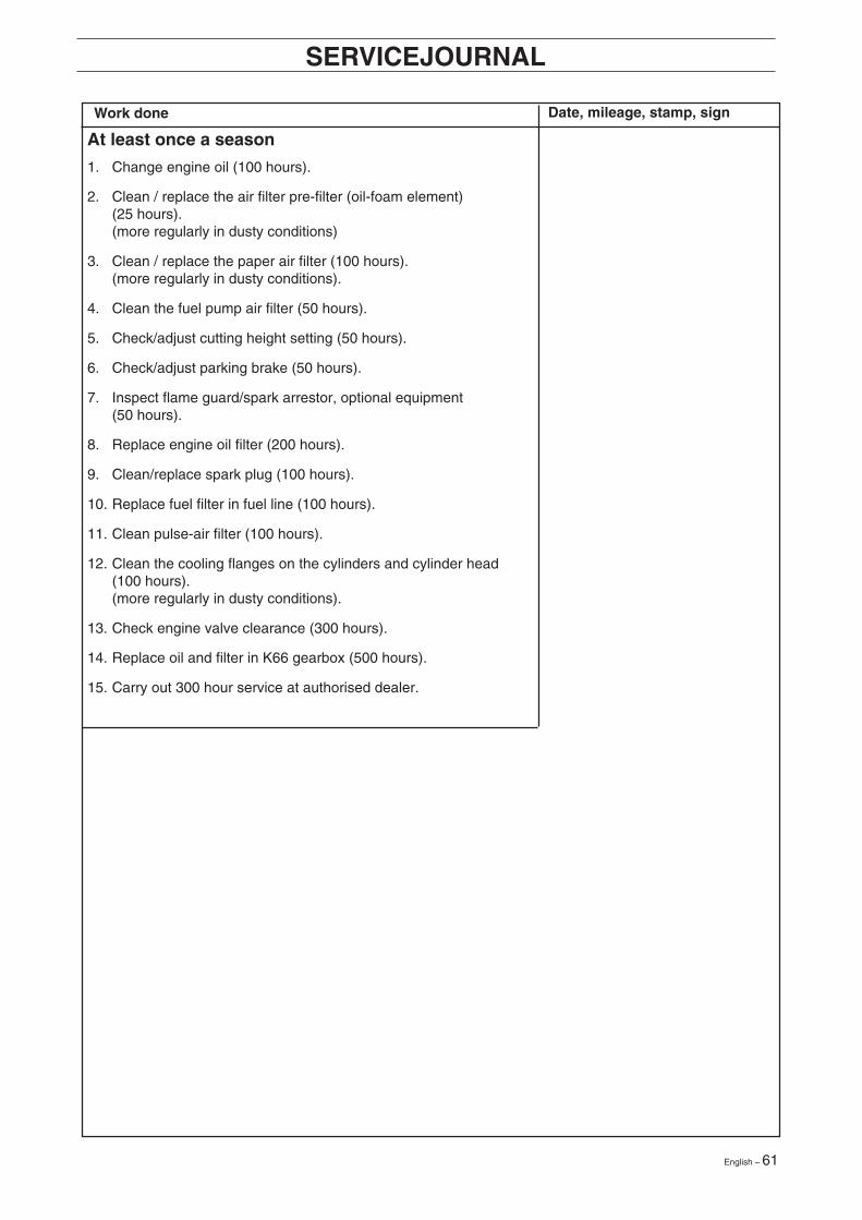
English – 61
SERVICEJOURNAL
Work done Date, mileage, stamp, sign
At least once a season
1. Change engine oil (100 hours).
2. Clean / replace the air filter pre-filter (oil-foam element)(25 hours).(more regularly in dusty conditions)
3. Clean / replace the paper air filter (100 hours).(more regularly in dusty conditions).
4. Clean the fuel pump air filter (50 hours).
5. Check/adjust cutting height setting (50 hours).
6. Check/adjust parking brake (50 hours).
7. Inspect flame guard/spark arrestor, optional equipment(50 hours).
8. Replace engine oil filter (200 hours).
9. Clean/replace spark plug (100 hours).
10. Replace fuel filter in fuel line (100 hours).
11. Clean pulse-air filter (100 hours).
12. Clean the cooling flanges on the cylinders and cylinder head(100 hours).(more regularly in dusty conditions).
13. Check engine valve clearance (300 hours).
14. Replace oil and filter in K66 gearbox (500 hours).
15. Carry out 300 hour service at authorised dealer.

62 – English
○ ○ ○ ○ ○ ○ ○ ○ ○ ○ ○ ○ ○ ○ ○ ○ ○ ○ ○ ○ ○ ○ ○ ○ ○ ○ ○ ○ ○ ○ ○ ○ ○ ○ ○ ○ ○ ○ ○ ○ ○ ○ ○ ○ ○ ○ ○ ○ ○ ○ ○ ○ ○ ○ ○ ○ ○ ○ ○ ○ ○
○ ○ ○ ○ ○ ○ ○ ○ ○ ○ ○ ○ ○ ○ ○ ○ ○ ○ ○ ○ ○ ○ ○ ○ ○ ○ ○ ○ ○ ○ ○ ○ ○ ○ ○ ○ ○ ○ ○ ○ ○ ○ ○ ○ ○ ○ ○ ○ ○ ○ ○ ○ ○ ○ ○ ○ ○ ○ ○ ○ ○
○ ○ ○ ○ ○ ○ ○ ○ ○ ○ ○ ○ ○ ○ ○ ○ ○ ○ ○ ○ ○ ○ ○ ○ ○ ○ ○ ○ ○ ○ ○ ○ ○ ○ ○ ○ ○ ○ ○ ○ ○ ○ ○ ○ ○ ○ ○ ○ ○ ○ ○ ○ ○ ○ ○ ○ ○ ○ ○ ○ ○○ ○ ○ ○ ○ ○ ○ ○ ○ ○ ○ ○ ○ ○ ○ ○ ○ ○ ○ ○ ○ ○ ○ ○ ○ ○ ○ ○ ○ ○ ○ ○ ○ ○ ○ ○ ○ ○ ○ ○ ○ ○ ○ ○ ○ ○ ○ ○ ○ ○ ○ ○ ○ ○ ○ ○ ○ ○ ○ ○ ○
○ ○ ○ ○ ○ ○ ○ ○ ○ ○ ○ ○ ○ ○ ○ ○ ○ ○ ○ ○ ○ ○ ○ ○ ○ ○ ○ ○ ○ ○ ○ ○ ○ ○ ○ ○ ○ ○ ○ ○ ○ ○ ○ ○ ○ ○ ○ ○ ○ ○ ○ ○ ○ ○ ○ ○ ○ ○ ○ ○ ○
○ ○ ○ ○ ○ ○ ○ ○ ○ ○ ○ ○ ○ ○ ○ ○ ○ ○ ○ ○ ○ ○ ○ ○ ○ ○ ○ ○ ○ ○ ○ ○ ○ ○ ○ ○ ○ ○ ○ ○ ○ ○ ○ ○ ○ ○ ○ ○ ○ ○ ○ ○ ○ ○ ○ ○ ○ ○ ○ ○ ○
○ ○ ○ ○ ○ ○ ○ ○ ○ ○ ○ ○ ○ ○ ○ ○ ○ ○ ○ ○ ○ ○ ○ ○ ○ ○ ○ ○ ○ ○ ○ ○ ○ ○ ○ ○ ○ ○ ○ ○ ○ ○ ○ ○ ○ ○ ○ ○ ○ ○ ○ ○ ○ ○ ○ ○ ○ ○ ○ ○ ○
○ ○ ○ ○ ○ ○ ○ ○ ○ ○ ○ ○ ○ ○ ○ ○ ○ ○ ○ ○ ○ ○ ○ ○ ○ ○ ○ ○ ○ ○ ○ ○ ○ ○ ○ ○ ○ ○ ○ ○ ○ ○ ○ ○ ○ ○ ○ ○ ○ ○ ○ ○ ○ ○ ○ ○ ○ ○ ○ ○ ○
○ ○ ○ ○ ○ ○ ○ ○ ○ ○ ○ ○ ○ ○ ○ ○ ○ ○ ○ ○ ○ ○ ○ ○ ○ ○ ○ ○ ○ ○ ○ ○ ○ ○ ○ ○ ○ ○ ○ ○ ○ ○ ○ ○ ○ ○ ○ ○ ○ ○ ○ ○ ○ ○ ○ ○ ○ ○ ○ ○ ○
○ ○ ○ ○ ○ ○ ○ ○ ○ ○ ○ ○ ○ ○ ○ ○ ○ ○ ○ ○ ○ ○ ○ ○ ○ ○ ○ ○ ○ ○ ○ ○ ○ ○ ○ ○ ○ ○ ○ ○ ○ ○ ○ ○ ○ ○ ○ ○ ○ ○ ○ ○ ○ ○ ○ ○ ○ ○ ○ ○ ○
○ ○ ○ ○ ○ ○ ○ ○ ○ ○ ○ ○ ○ ○ ○ ○ ○ ○ ○ ○ ○ ○ ○ ○ ○ ○ ○ ○ ○ ○ ○ ○ ○ ○ ○ ○ ○ ○ ○ ○ ○ ○ ○ ○ ○ ○ ○ ○ ○ ○ ○ ○ ○ ○ ○ ○ ○ ○ ○ ○ ○
○ ○ ○ ○ ○ ○ ○ ○ ○ ○ ○ ○ ○ ○ ○ ○ ○ ○ ○ ○ ○ ○ ○ ○ ○ ○ ○ ○ ○ ○ ○ ○ ○ ○ ○ ○ ○ ○ ○ ○ ○ ○ ○ ○ ○ ○ ○ ○ ○ ○ ○ ○ ○ ○ ○ ○ ○ ○ ○ ○ ○
○ ○ ○ ○ ○ ○ ○ ○ ○ ○ ○ ○ ○ ○ ○ ○ ○ ○ ○ ○ ○ ○ ○ ○ ○ ○ ○ ○ ○ ○ ○ ○ ○ ○ ○ ○ ○ ○ ○ ○ ○ ○ ○ ○ ○ ○ ○ ○ ○ ○ ○ ○ ○ ○ ○ ○ ○ ○ ○ ○ ○
○ ○ ○ ○ ○ ○ ○ ○ ○ ○ ○ ○ ○ ○ ○ ○ ○ ○ ○ ○ ○ ○ ○ ○ ○ ○ ○ ○ ○ ○ ○ ○ ○ ○ ○ ○ ○ ○ ○ ○ ○ ○ ○ ○ ○ ○ ○ ○ ○ ○ ○ ○ ○ ○ ○ ○ ○ ○ ○ ○ ○
○ ○ ○ ○ ○ ○ ○ ○ ○ ○ ○ ○ ○ ○ ○ ○ ○ ○ ○ ○ ○ ○ ○ ○ ○ ○ ○ ○ ○ ○ ○ ○ ○ ○ ○ ○ ○ ○ ○ ○ ○ ○ ○ ○ ○ ○ ○ ○ ○ ○ ○ ○ ○ ○ ○ ○ ○ ○ ○ ○ ○
○ ○ ○ ○ ○ ○ ○ ○ ○ ○ ○ ○ ○ ○ ○ ○ ○ ○ ○ ○ ○ ○ ○ ○ ○ ○ ○ ○ ○ ○ ○ ○ ○ ○ ○ ○ ○ ○ ○ ○ ○ ○ ○ ○ ○ ○ ○ ○ ○ ○ ○ ○ ○ ○ ○ ○ ○ ○ ○ ○ ○
○ ○ ○ ○ ○ ○ ○ ○ ○ ○ ○ ○ ○ ○ ○ ○ ○ ○ ○ ○ ○ ○ ○ ○ ○ ○ ○ ○ ○ ○ ○ ○ ○ ○ ○ ○ ○ ○ ○ ○ ○ ○ ○ ○ ○ ○ ○ ○ ○ ○ ○ ○ ○ ○ ○ ○ ○ ○ ○ ○ ○
○ ○ ○ ○ ○ ○ ○ ○ ○ ○ ○ ○ ○ ○ ○ ○ ○ ○ ○ ○ ○ ○ ○ ○ ○ ○ ○ ○ ○ ○ ○ ○ ○ ○ ○ ○ ○ ○ ○ ○ ○ ○ ○ ○ ○ ○ ○ ○ ○ ○ ○ ○ ○ ○ ○ ○ ○ ○ ○ ○ ○
○ ○ ○ ○ ○ ○ ○ ○ ○ ○ ○ ○ ○ ○ ○ ○ ○ ○ ○ ○ ○ ○ ○ ○ ○ ○ ○ ○ ○ ○ ○ ○ ○ ○ ○ ○ ○ ○ ○ ○ ○ ○ ○ ○ ○ ○ ○ ○ ○ ○ ○ ○ ○ ○ ○ ○ ○ ○ ○ ○ ○
○ ○ ○ ○ ○ ○ ○ ○ ○ ○ ○ ○ ○ ○ ○ ○ ○ ○ ○ ○ ○ ○ ○ ○ ○ ○ ○ ○ ○ ○ ○ ○ ○ ○ ○ ○ ○ ○ ○ ○ ○ ○ ○ ○ ○ ○ ○ ○ ○ ○ ○ ○ ○ ○ ○ ○ ○ ○ ○ ○ ○
○ ○ ○ ○ ○ ○ ○ ○ ○ ○ ○ ○ ○ ○ ○ ○ ○ ○ ○ ○ ○ ○ ○ ○ ○ ○ ○ ○ ○ ○ ○ ○ ○ ○ ○ ○ ○ ○ ○ ○ ○ ○ ○ ○ ○ ○ ○ ○ ○ ○ ○ ○ ○ ○ ○ ○ ○ ○ ○ ○ ○
○ ○ ○ ○ ○ ○ ○ ○ ○ ○ ○ ○ ○ ○ ○ ○ ○ ○ ○ ○ ○ ○ ○ ○ ○ ○ ○ ○ ○ ○ ○ ○ ○ ○ ○ ○ ○ ○ ○ ○ ○ ○ ○ ○ ○ ○ ○ ○ ○ ○ ○ ○ ○ ○ ○ ○ ○ ○ ○ ○ ○
○ ○ ○ ○ ○ ○ ○ ○ ○ ○ ○ ○ ○ ○ ○ ○ ○ ○ ○ ○ ○ ○ ○ ○ ○ ○ ○ ○ ○ ○ ○ ○ ○ ○ ○ ○ ○ ○ ○ ○ ○ ○ ○ ○ ○ ○ ○ ○ ○ ○ ○ ○ ○ ○ ○ ○ ○ ○ ○ ○ ○
○ ○ ○ ○ ○ ○ ○ ○ ○ ○ ○ ○ ○ ○ ○ ○ ○ ○ ○ ○ ○ ○ ○ ○ ○ ○ ○ ○ ○ ○ ○ ○ ○ ○ ○ ○ ○ ○ ○ ○ ○ ○ ○ ○ ○ ○ ○ ○ ○ ○ ○ ○ ○ ○ ○ ○ ○ ○ ○ ○ ○
○ ○ ○ ○ ○ ○ ○ ○ ○ ○ ○ ○ ○ ○ ○ ○ ○ ○ ○ ○ ○ ○ ○ ○ ○ ○ ○ ○ ○ ○ ○ ○ ○ ○ ○ ○ ○ ○ ○ ○ ○ ○ ○ ○ ○ ○ ○ ○ ○ ○ ○ ○ ○ ○ ○ ○ ○ ○ ○ ○ ○
SERVICEJOURNAL
Work done Date, mileage, stamp, sign
English – 63
○ ○ ○ ○ ○ ○ ○ ○ ○ ○ ○ ○ ○ ○ ○ ○ ○ ○ ○ ○ ○ ○ ○ ○ ○ ○ ○ ○ ○ ○ ○ ○ ○ ○ ○ ○ ○ ○ ○ ○ ○ ○ ○ ○ ○ ○ ○ ○ ○ ○ ○ ○ ○ ○ ○ ○ ○ ○ ○ ○ ○
○ ○ ○ ○ ○ ○ ○ ○ ○ ○ ○ ○ ○ ○ ○ ○ ○ ○ ○ ○ ○ ○ ○ ○ ○ ○ ○ ○ ○ ○ ○ ○ ○ ○ ○ ○ ○ ○ ○ ○ ○ ○ ○ ○ ○ ○ ○ ○ ○ ○ ○ ○ ○ ○ ○ ○ ○ ○ ○ ○ ○
○ ○ ○ ○ ○ ○ ○ ○ ○ ○ ○ ○ ○ ○ ○ ○ ○ ○ ○ ○ ○ ○ ○ ○ ○ ○ ○ ○ ○ ○ ○ ○ ○ ○ ○ ○ ○ ○ ○ ○ ○ ○ ○ ○ ○ ○ ○ ○ ○ ○ ○ ○ ○ ○ ○ ○ ○ ○ ○ ○ ○○ ○ ○ ○ ○ ○ ○ ○ ○ ○ ○ ○ ○ ○ ○ ○ ○ ○ ○ ○ ○ ○ ○ ○ ○ ○ ○ ○ ○ ○ ○ ○ ○ ○ ○ ○ ○ ○ ○ ○ ○ ○ ○ ○ ○ ○ ○ ○ ○ ○ ○ ○ ○ ○ ○ ○ ○ ○ ○ ○ ○
○ ○ ○ ○ ○ ○ ○ ○ ○ ○ ○ ○ ○ ○ ○ ○ ○ ○ ○ ○ ○ ○ ○ ○ ○ ○ ○ ○ ○ ○ ○ ○ ○ ○ ○ ○ ○ ○ ○ ○ ○ ○ ○ ○ ○ ○ ○ ○ ○ ○ ○ ○ ○ ○ ○ ○ ○ ○ ○ ○ ○
○ ○ ○ ○ ○ ○ ○ ○ ○ ○ ○ ○ ○ ○ ○ ○ ○ ○ ○ ○ ○ ○ ○ ○ ○ ○ ○ ○ ○ ○ ○ ○ ○ ○ ○ ○ ○ ○ ○ ○ ○ ○ ○ ○ ○ ○ ○ ○ ○ ○ ○ ○ ○ ○ ○ ○ ○ ○ ○ ○ ○
○ ○ ○ ○ ○ ○ ○ ○ ○ ○ ○ ○ ○ ○ ○ ○ ○ ○ ○ ○ ○ ○ ○ ○ ○ ○ ○ ○ ○ ○ ○ ○ ○ ○ ○ ○ ○ ○ ○ ○ ○ ○ ○ ○ ○ ○ ○ ○ ○ ○ ○ ○ ○ ○ ○ ○ ○ ○ ○ ○ ○
○ ○ ○ ○ ○ ○ ○ ○ ○ ○ ○ ○ ○ ○ ○ ○ ○ ○ ○ ○ ○ ○ ○ ○ ○ ○ ○ ○ ○ ○ ○ ○ ○ ○ ○ ○ ○ ○ ○ ○ ○ ○ ○ ○ ○ ○ ○ ○ ○ ○ ○ ○ ○ ○ ○ ○ ○ ○ ○ ○ ○
○ ○ ○ ○ ○ ○ ○ ○ ○ ○ ○ ○ ○ ○ ○ ○ ○ ○ ○ ○ ○ ○ ○ ○ ○ ○ ○ ○ ○ ○ ○ ○ ○ ○ ○ ○ ○ ○ ○ ○ ○ ○ ○ ○ ○ ○ ○ ○ ○ ○ ○ ○ ○ ○ ○ ○ ○ ○ ○ ○ ○
○ ○ ○ ○ ○ ○ ○ ○ ○ ○ ○ ○ ○ ○ ○ ○ ○ ○ ○ ○ ○ ○ ○ ○ ○ ○ ○ ○ ○ ○ ○ ○ ○ ○ ○ ○ ○ ○ ○ ○ ○ ○ ○ ○ ○ ○ ○ ○ ○ ○ ○ ○ ○ ○ ○ ○ ○ ○ ○ ○ ○
○ ○ ○ ○ ○ ○ ○ ○ ○ ○ ○ ○ ○ ○ ○ ○ ○ ○ ○ ○ ○ ○ ○ ○ ○ ○ ○ ○ ○ ○ ○ ○ ○ ○ ○ ○ ○ ○ ○ ○ ○ ○ ○ ○ ○ ○ ○ ○ ○ ○ ○ ○ ○ ○ ○ ○ ○ ○ ○ ○ ○
○ ○ ○ ○ ○ ○ ○ ○ ○ ○ ○ ○ ○ ○ ○ ○ ○ ○ ○ ○ ○ ○ ○ ○ ○ ○ ○ ○ ○ ○ ○ ○ ○ ○ ○ ○ ○ ○ ○ ○ ○ ○ ○ ○ ○ ○ ○ ○ ○ ○ ○ ○ ○ ○ ○ ○ ○ ○ ○ ○ ○
○ ○ ○ ○ ○ ○ ○ ○ ○ ○ ○ ○ ○ ○ ○ ○ ○ ○ ○ ○ ○ ○ ○ ○ ○ ○ ○ ○ ○ ○ ○ ○ ○ ○ ○ ○ ○ ○ ○ ○ ○ ○ ○ ○ ○ ○ ○ ○ ○ ○ ○ ○ ○ ○ ○ ○ ○ ○ ○ ○ ○
○ ○ ○ ○ ○ ○ ○ ○ ○ ○ ○ ○ ○ ○ ○ ○ ○ ○ ○ ○ ○ ○ ○ ○ ○ ○ ○ ○ ○ ○ ○ ○ ○ ○ ○ ○ ○ ○ ○ ○ ○ ○ ○ ○ ○ ○ ○ ○ ○ ○ ○ ○ ○ ○ ○ ○ ○ ○ ○ ○ ○
○ ○ ○ ○ ○ ○ ○ ○ ○ ○ ○ ○ ○ ○ ○ ○ ○ ○ ○ ○ ○ ○ ○ ○ ○ ○ ○ ○ ○ ○ ○ ○ ○ ○ ○ ○ ○ ○ ○ ○ ○ ○ ○ ○ ○ ○ ○ ○ ○ ○ ○ ○ ○ ○ ○ ○ ○ ○ ○ ○ ○
○ ○ ○ ○ ○ ○ ○ ○ ○ ○ ○ ○ ○ ○ ○ ○ ○ ○ ○ ○ ○ ○ ○ ○ ○ ○ ○ ○ ○ ○ ○ ○ ○ ○ ○ ○ ○ ○ ○ ○ ○ ○ ○ ○ ○ ○ ○ ○ ○ ○ ○ ○ ○ ○ ○ ○ ○ ○ ○ ○ ○
○ ○ ○ ○ ○ ○ ○ ○ ○ ○ ○ ○ ○ ○ ○ ○ ○ ○ ○ ○ ○ ○ ○ ○ ○ ○ ○ ○ ○ ○ ○ ○ ○ ○ ○ ○ ○ ○ ○ ○ ○ ○ ○ ○ ○ ○ ○ ○ ○ ○ ○ ○ ○ ○ ○ ○ ○ ○ ○ ○ ○
○ ○ ○ ○ ○ ○ ○ ○ ○ ○ ○ ○ ○ ○ ○ ○ ○ ○ ○ ○ ○ ○ ○ ○ ○ ○ ○ ○ ○ ○ ○ ○ ○ ○ ○ ○ ○ ○ ○ ○ ○ ○ ○ ○ ○ ○ ○ ○ ○ ○ ○ ○ ○ ○ ○ ○ ○ ○ ○ ○ ○
○ ○ ○ ○ ○ ○ ○ ○ ○ ○ ○ ○ ○ ○ ○ ○ ○ ○ ○ ○ ○ ○ ○ ○ ○ ○ ○ ○ ○ ○ ○ ○ ○ ○ ○ ○ ○ ○ ○ ○ ○ ○ ○ ○ ○ ○ ○ ○ ○ ○ ○ ○ ○ ○ ○ ○ ○ ○ ○ ○ ○
○ ○ ○ ○ ○ ○ ○ ○ ○ ○ ○ ○ ○ ○ ○ ○ ○ ○ ○ ○ ○ ○ ○ ○ ○ ○ ○ ○ ○ ○ ○ ○ ○ ○ ○ ○ ○ ○ ○ ○ ○ ○ ○ ○ ○ ○ ○ ○ ○ ○ ○ ○ ○ ○ ○ ○ ○ ○ ○ ○ ○
○ ○ ○ ○ ○ ○ ○ ○ ○ ○ ○ ○ ○ ○ ○ ○ ○ ○ ○ ○ ○ ○ ○ ○ ○ ○ ○ ○ ○ ○ ○ ○ ○ ○ ○ ○ ○ ○ ○ ○ ○ ○ ○ ○ ○ ○ ○ ○ ○ ○ ○ ○ ○ ○ ○ ○ ○ ○ ○ ○ ○
○ ○ ○ ○ ○ ○ ○ ○ ○ ○ ○ ○ ○ ○ ○ ○ ○ ○ ○ ○ ○ ○ ○ ○ ○ ○ ○ ○ ○ ○ ○ ○ ○ ○ ○ ○ ○ ○ ○ ○ ○ ○ ○ ○ ○ ○ ○ ○ ○ ○ ○ ○ ○ ○ ○ ○ ○ ○ ○ ○ ○
○ ○ ○ ○ ○ ○ ○ ○ ○ ○ ○ ○ ○ ○ ○ ○ ○ ○ ○ ○ ○ ○ ○ ○ ○ ○ ○ ○ ○ ○ ○ ○ ○ ○ ○ ○ ○ ○ ○ ○ ○ ○ ○ ○ ○ ○ ○ ○ ○ ○ ○ ○ ○ ○ ○ ○ ○ ○ ○ ○ ○
○ ○ ○ ○ ○ ○ ○ ○ ○ ○ ○ ○ ○ ○ ○ ○ ○ ○ ○ ○ ○ ○ ○ ○ ○ ○ ○ ○ ○ ○ ○ ○ ○ ○ ○ ○ ○ ○ ○ ○ ○ ○ ○ ○ ○ ○ ○ ○ ○ ○ ○ ○ ○ ○ ○ ○ ○ ○ ○ ○ ○
○ ○ ○ ○ ○ ○ ○ ○ ○ ○ ○ ○ ○ ○ ○ ○ ○ ○ ○ ○ ○ ○ ○ ○ ○ ○ ○ ○ ○ ○ ○ ○ ○ ○ ○ ○ ○ ○ ○ ○ ○ ○ ○ ○ ○ ○ ○ ○ ○ ○ ○ ○ ○ ○ ○ ○ ○ ○ ○ ○ ○
SERVICEJOURNAL
Work done Date, mileage, stamp, sign
64 – English
○ ○ ○ ○ ○ ○ ○ ○ ○ ○ ○ ○ ○ ○ ○ ○ ○ ○ ○ ○ ○ ○ ○ ○ ○ ○ ○ ○ ○ ○ ○ ○ ○ ○ ○ ○ ○ ○ ○ ○ ○ ○ ○ ○ ○ ○ ○ ○ ○ ○ ○ ○ ○ ○ ○ ○ ○ ○ ○ ○ ○
○ ○ ○ ○ ○ ○ ○ ○ ○ ○ ○ ○ ○ ○ ○ ○ ○ ○ ○ ○ ○ ○ ○ ○ ○ ○ ○ ○ ○ ○ ○ ○ ○ ○ ○ ○ ○ ○ ○ ○ ○ ○ ○ ○ ○ ○ ○ ○ ○ ○ ○ ○ ○ ○ ○ ○ ○ ○ ○ ○ ○
○ ○ ○ ○ ○ ○ ○ ○ ○ ○ ○ ○ ○ ○ ○ ○ ○ ○ ○ ○ ○ ○ ○ ○ ○ ○ ○ ○ ○ ○ ○ ○ ○ ○ ○ ○ ○ ○ ○ ○ ○ ○ ○ ○ ○ ○ ○ ○ ○ ○ ○ ○ ○ ○ ○ ○ ○ ○ ○ ○ ○○ ○ ○ ○ ○ ○ ○ ○ ○ ○ ○ ○ ○ ○ ○ ○ ○ ○ ○ ○ ○ ○ ○ ○ ○ ○ ○ ○ ○ ○ ○ ○ ○ ○ ○ ○ ○ ○ ○ ○ ○ ○ ○ ○ ○ ○ ○ ○ ○ ○ ○ ○ ○ ○ ○ ○ ○ ○ ○ ○ ○
○ ○ ○ ○ ○ ○ ○ ○ ○ ○ ○ ○ ○ ○ ○ ○ ○ ○ ○ ○ ○ ○ ○ ○ ○ ○ ○ ○ ○ ○ ○ ○ ○ ○ ○ ○ ○ ○ ○ ○ ○ ○ ○ ○ ○ ○ ○ ○ ○ ○ ○ ○ ○ ○ ○ ○ ○ ○ ○ ○ ○
○ ○ ○ ○ ○ ○ ○ ○ ○ ○ ○ ○ ○ ○ ○ ○ ○ ○ ○ ○ ○ ○ ○ ○ ○ ○ ○ ○ ○ ○ ○ ○ ○ ○ ○ ○ ○ ○ ○ ○ ○ ○ ○ ○ ○ ○ ○ ○ ○ ○ ○ ○ ○ ○ ○ ○ ○ ○ ○ ○ ○
○ ○ ○ ○ ○ ○ ○ ○ ○ ○ ○ ○ ○ ○ ○ ○ ○ ○ ○ ○ ○ ○ ○ ○ ○ ○ ○ ○ ○ ○ ○ ○ ○ ○ ○ ○ ○ ○ ○ ○ ○ ○ ○ ○ ○ ○ ○ ○ ○ ○ ○ ○ ○ ○ ○ ○ ○ ○ ○ ○ ○
○ ○ ○ ○ ○ ○ ○ ○ ○ ○ ○ ○ ○ ○ ○ ○ ○ ○ ○ ○ ○ ○ ○ ○ ○ ○ ○ ○ ○ ○ ○ ○ ○ ○ ○ ○ ○ ○ ○ ○ ○ ○ ○ ○ ○ ○ ○ ○ ○ ○ ○ ○ ○ ○ ○ ○ ○ ○ ○ ○ ○
○ ○ ○ ○ ○ ○ ○ ○ ○ ○ ○ ○ ○ ○ ○ ○ ○ ○ ○ ○ ○ ○ ○ ○ ○ ○ ○ ○ ○ ○ ○ ○ ○ ○ ○ ○ ○ ○ ○ ○ ○ ○ ○ ○ ○ ○ ○ ○ ○ ○ ○ ○ ○ ○ ○ ○ ○ ○ ○ ○ ○
○ ○ ○ ○ ○ ○ ○ ○ ○ ○ ○ ○ ○ ○ ○ ○ ○ ○ ○ ○ ○ ○ ○ ○ ○ ○ ○ ○ ○ ○ ○ ○ ○ ○ ○ ○ ○ ○ ○ ○ ○ ○ ○ ○ ○ ○ ○ ○ ○ ○ ○ ○ ○ ○ ○ ○ ○ ○ ○ ○ ○
○ ○ ○ ○ ○ ○ ○ ○ ○ ○ ○ ○ ○ ○ ○ ○ ○ ○ ○ ○ ○ ○ ○ ○ ○ ○ ○ ○ ○ ○ ○ ○ ○ ○ ○ ○ ○ ○ ○ ○ ○ ○ ○ ○ ○ ○ ○ ○ ○ ○ ○ ○ ○ ○ ○ ○ ○ ○ ○ ○ ○
○ ○ ○ ○ ○ ○ ○ ○ ○ ○ ○ ○ ○ ○ ○ ○ ○ ○ ○ ○ ○ ○ ○ ○ ○ ○ ○ ○ ○ ○ ○ ○ ○ ○ ○ ○ ○ ○ ○ ○ ○ ○ ○ ○ ○ ○ ○ ○ ○ ○ ○ ○ ○ ○ ○ ○ ○ ○ ○ ○ ○
○ ○ ○ ○ ○ ○ ○ ○ ○ ○ ○ ○ ○ ○ ○ ○ ○ ○ ○ ○ ○ ○ ○ ○ ○ ○ ○ ○ ○ ○ ○ ○ ○ ○ ○ ○ ○ ○ ○ ○ ○ ○ ○ ○ ○ ○ ○ ○ ○ ○ ○ ○ ○ ○ ○ ○ ○ ○ ○ ○ ○
○ ○ ○ ○ ○ ○ ○ ○ ○ ○ ○ ○ ○ ○ ○ ○ ○ ○ ○ ○ ○ ○ ○ ○ ○ ○ ○ ○ ○ ○ ○ ○ ○ ○ ○ ○ ○ ○ ○ ○ ○ ○ ○ ○ ○ ○ ○ ○ ○ ○ ○ ○ ○ ○ ○ ○ ○ ○ ○ ○ ○
○ ○ ○ ○ ○ ○ ○ ○ ○ ○ ○ ○ ○ ○ ○ ○ ○ ○ ○ ○ ○ ○ ○ ○ ○ ○ ○ ○ ○ ○ ○ ○ ○ ○ ○ ○ ○ ○ ○ ○ ○ ○ ○ ○ ○ ○ ○ ○ ○ ○ ○ ○ ○ ○ ○ ○ ○ ○ ○ ○ ○
○ ○ ○ ○ ○ ○ ○ ○ ○ ○ ○ ○ ○ ○ ○ ○ ○ ○ ○ ○ ○ ○ ○ ○ ○ ○ ○ ○ ○ ○ ○ ○ ○ ○ ○ ○ ○ ○ ○ ○ ○ ○ ○ ○ ○ ○ ○ ○ ○ ○ ○ ○ ○ ○ ○ ○ ○ ○ ○ ○ ○
○ ○ ○ ○ ○ ○ ○ ○ ○ ○ ○ ○ ○ ○ ○ ○ ○ ○ ○ ○ ○ ○ ○ ○ ○ ○ ○ ○ ○ ○ ○ ○ ○ ○ ○ ○ ○ ○ ○ ○ ○ ○ ○ ○ ○ ○ ○ ○ ○ ○ ○ ○ ○ ○ ○ ○ ○ ○ ○ ○ ○
○ ○ ○ ○ ○ ○ ○ ○ ○ ○ ○ ○ ○ ○ ○ ○ ○ ○ ○ ○ ○ ○ ○ ○ ○ ○ ○ ○ ○ ○ ○ ○ ○ ○ ○ ○ ○ ○ ○ ○ ○ ○ ○ ○ ○ ○ ○ ○ ○ ○ ○ ○ ○ ○ ○ ○ ○ ○ ○ ○ ○
○ ○ ○ ○ ○ ○ ○ ○ ○ ○ ○ ○ ○ ○ ○ ○ ○ ○ ○ ○ ○ ○ ○ ○ ○ ○ ○ ○ ○ ○ ○ ○ ○ ○ ○ ○ ○ ○ ○ ○ ○ ○ ○ ○ ○ ○ ○ ○ ○ ○ ○ ○ ○ ○ ○ ○ ○ ○ ○ ○ ○
○ ○ ○ ○ ○ ○ ○ ○ ○ ○ ○ ○ ○ ○ ○ ○ ○ ○ ○ ○ ○ ○ ○ ○ ○ ○ ○ ○ ○ ○ ○ ○ ○ ○ ○ ○ ○ ○ ○ ○ ○ ○ ○ ○ ○ ○ ○ ○ ○ ○ ○ ○ ○ ○ ○ ○ ○ ○ ○ ○ ○
○ ○ ○ ○ ○ ○ ○ ○ ○ ○ ○ ○ ○ ○ ○ ○ ○ ○ ○ ○ ○ ○ ○ ○ ○ ○ ○ ○ ○ ○ ○ ○ ○ ○ ○ ○ ○ ○ ○ ○ ○ ○ ○ ○ ○ ○ ○ ○ ○ ○ ○ ○ ○ ○ ○ ○ ○ ○ ○ ○ ○
○ ○ ○ ○ ○ ○ ○ ○ ○ ○ ○ ○ ○ ○ ○ ○ ○ ○ ○ ○ ○ ○ ○ ○ ○ ○ ○ ○ ○ ○ ○ ○ ○ ○ ○ ○ ○ ○ ○ ○ ○ ○ ○ ○ ○ ○ ○ ○ ○ ○ ○ ○ ○ ○ ○ ○ ○ ○ ○ ○ ○
○ ○ ○ ○ ○ ○ ○ ○ ○ ○ ○ ○ ○ ○ ○ ○ ○ ○ ○ ○ ○ ○ ○ ○ ○ ○ ○ ○ ○ ○ ○ ○ ○ ○ ○ ○ ○ ○ ○ ○ ○ ○ ○ ○ ○ ○ ○ ○ ○ ○ ○ ○ ○ ○ ○ ○ ○ ○ ○ ○ ○
○ ○ ○ ○ ○ ○ ○ ○ ○ ○ ○ ○ ○ ○ ○ ○ ○ ○ ○ ○ ○ ○ ○ ○ ○ ○ ○ ○ ○ ○ ○ ○ ○ ○ ○ ○ ○ ○ ○ ○ ○ ○ ○ ○ ○ ○ ○ ○ ○ ○ ○ ○ ○ ○ ○ ○ ○ ○ ○ ○ ○
○ ○ ○ ○ ○ ○ ○ ○ ○ ○ ○ ○ ○ ○ ○ ○ ○ ○ ○ ○ ○ ○ ○ ○ ○ ○ ○ ○ ○ ○ ○ ○ ○ ○ ○ ○ ○ ○ ○ ○ ○ ○ ○ ○ ○ ○ ○ ○ ○ ○ ○ ○ ○ ○ ○ ○ ○ ○ ○ ○ ○
SERVICEJOURNAL
Work done Date, mileage, stamp, sign
´+H%6¶6$¨

English – 65

´+H%6¶6$¨2002W11
114 00 52-26