operator’s manual - scag giant-vacgiant-vac.com/manuals/truck...
TRANSCRIPT

PART NO. 03350PRINTED 7/2013PRINTED IN USA
© 2013Scag Giant-VacDivision of Metalcraft of Mayville, Inc.
Congratulations on owning a Scag Giant-Vac truck loader! This manual contains the operating instructions and safety information for your Scag Giant-Vac truck loader. Reading this manual can provide you with assistance in maintenance and adjustment procedures to keep your truck loader performing to maximum efficiency. The specific models that this book covers are listed on the inside cover. Before operating your truck loader, please read all the information enclosed.
OPERATOR’S MANUAL
TRUCK LOADERTow BehindModel: TL20W-29BV TL20W-26CH-EFI

WARNINGFAILURE TO FOLLOW SAFE OPERATING PRACTICES MAY RESULT
IN SERIOUS INJURY OR DEATH.
Read this manual completely as well as other manuals that came with your truck •loader.
ALWAYS FOLLOW OSHA APPROVED OPERATION.•
Become familiar with the safe operation of the equipment, operator controls and •safety signs.
Check operation of brake, tail, marker and license plate lights frequently. Replace as •required.
Make sure the operator of the tow vehicle has the operator of the truck loader in full •view at all times. Also, when operating the unit, instruct the operator to stay to the side of the machine, never in front or behind.
Keep all shields and guards securely in place.•
Be sure all safety features are attached, adjusted and functioning properly.•
Before performing any maintenance or service, stop the machine and remove the •spark plug wire.
If a mechanism becomes clogged, stop the engine and wait for all moving parts to •stop before cleaning.
Keep hands, feet and clothing away from power-driven parts.•
REMEMBER - YOUR TRUCK LOADER IS ONLY AS SAFE AS THE OPERATOR!
HAzARD CONTROL AND ACCIDENT PREvENTION ARE DEPENDENT UPON THE AWARENESS, CONCERN, PRUDENCE, AND PROPER TRAINING OF THE PERSONNEL INvOLvED IN THE OPERATION, TRANSPORT, MAINTENANCE, AND STORAGE OF THE EqUIPMENT.
This manual covers the operating instructions and illustrated parts list for:
TL20W-29Bv with a serial number of 009A00001 to 009A99999
TL20W-26CH-EFI with a serial number of 010A00001 to 010A99999
Always use the entire serial number listed on the serial number tag when referring to this product.

I
RTable of Contents
Table of ContentsGENERAL INFORMATIONSECTION 1 - ...................................................................................1
1.1 INTRODUCTION ...........................................................................................................................................1
1.2 DIRECTION REFERENCE ...........................................................................................................................1
1.3 SERvICING THE ENGINE AND DRIvE TRAIN COMPONENTS .................................................................1
1.4 SYMBOLS ....................................................................................................................................................2
SAFETY INFORMATIONSECTION 2 - ......................................................................................32.1 INTRODUCTION ...........................................................................................................................................3
2.2 SIGNAL WORDS ..........................................................................................................................................3
2.3 BEFORE OPERATION CONSIDERATIONS ................................................................................................3
2.4 OPERATION CONSIDERATIONS ................................................................................................................5
2.5 MAINTENANCE CONSIDERATIONS & STORAGE ....................................................................................6
2.6 USING A SPARK ARRESTOR .....................................................................................................................6
2.7 SPARK IGNITION SYSTEM .........................................................................................................................6
2.8 SAFETY AND INSTRUCTIONAL DECALS .................................................................................................7
SPECIFICATIONSSECTION 3 - ................................................................................................83.1 ENGINE ........................................................................................................................................................8
3.2 IMPELLER ....................................................................................................................................................8
3.3 WEIGHTS AND DIMENSIONS .....................................................................................................................8
OPERATING INSTRUCTIONSSECTION 4 - ...........................................................................104.1 CONTROLS AND INSTRUMENT IDENTIFICATION ................................................................................10
4.2 INITIAL RUN-IN PROCEDURES ................................................................................................................11
4.3 CONNECTING TO TOW vEHICLE .............................................................................................................11
4.4 STARTING THE ENGINE ...........................................................................................................................12
4.5 OPERATION ...............................................................................................................................................12
4.6 HILLSIDE OPERATION ..............................................................................................................................13
4.7 UNCOUPLING THE UNIT FROM THE TOW vEHICLE ..............................................................................13
4.8 AFTER OPERATION ..................................................................................................................................14
4.9 REMOvING CLOGGED MATERIAL ..........................................................................................................15
MAINTENANCESECTION 5 - ..................................................................................................165.1 MAINTENANCE CHART - RECOMMENDED SERvICE INTERvALS ......................................................16
5.2 ENGINE OIL ...............................................................................................................................................17
5.3 ENGINE FUEL SYSTEM ............................................................................................................................17
5.4 ENGINE AIR CLEANER .............................................................................................................................17
5.5 WHEELS & TIRES ......................................................................................................................................17
5.6 TRAILER LIGHTS .......................................................................................................................................17
II
R Table of Contents
ILLUSTRATED PARTS LISTSECTION 6 - ..............................................................................186.1 SCAG GIANT-vAC APPROvED ATTACHMENTS AND ACCESSORIES..................................................18
NOTES ..............................................................................................................................................................19
INTAKE AND DISCHARGE ASSEMBLY .........................................................................................................20
INTAKE AND DISCHARGE ASSEMBLY .........................................................................................................21
IMPELLER ASSEMBLY ...................................................................................................................................22
IMPELLER ASSEMBLY ...................................................................................................................................23
TRAILER ASSEMBLY ......................................................................................................................................24
TRAILER ASSEMBLY ......................................................................................................................................25
FUEL SYSTEM .................................................................................................................................................26
FUEL SYSTEM .................................................................................................................................................27
ELECTRICAL SYSTEM ...................................................................................................................................28
ELECTRICAL SYSTEM ...................................................................................................................................29
TL20W - TRUCK LOADER DECALS ...............................................................................................................30
TL20W - TRAILER LIGHT WIRING DIAGRAM ...............................................................................................31
LIMITED WARRANTY - TRUCK LOADERS .........................................................................Inside Back Cover
1
Section 1
INTRODUCTION1.1
Your Scag Giant-Vac product was built to the highest standards in the industry. However, the prolonged life and maximum efficiency of your truck loader depends on you following the operating, maintenance and adjustment instructions in this manual.
If additional information or service is needed, contact your Scag Giant-Vac Dealer.
We encourage you to contact your dealer for repairs. All Scag Giant-Vac dealers are informed of the latest methods to service this equipment and provide prompt and efficient service in the field or at their service shop. They carry a full line of Scag Giant-Vac service parts.
- IMPORTANT -
The replacement of any part on this product by other than the manufacturer's authorized replacement part may adversely affect the performance, durability or safety of this product.
Use of other than original Scag Giant-Vac replacement parts will void the warranty.
When ordering parts, always give the model and serial number of your product. The serial number plate is located on the frame next to the engine.
USE ONLY SCAG GIANT-vAC APPROvED ATTACHMENTS AND ACCESSORIES.
Attachments and accessories manufactured by companies other than Scag Giant-Vac are not approved for use on this machine. See Section 6-1.
GENERAL INFORMATION
WARNINGFor pictorial clarity, some illustrations and figures in this manual may show shields, guards or plates open or removed. Under no circumstances should this product be operated without these devices in place.
All information is based upon product information available at the time of approval for printing. Scag Giant-Vac reserves the right to make changes at any time without notice and without incurring any obligation.
DIRECTION REFERENCE1.2
The “Right” and “Left”, “Front” and “Rear” of the machine are referenced from the operator’s right and left when in the normal operating position and facing the forward travel direction.
SERvICING THE ENGINE AND DRIvE 1.3 TRAIN COMPONENTS
Details regarding the service and repair of the engine are not covered in this manual; only routine maintenance and general service instructions are provided. For service of these components during the limited warranty period, it is important to contact your Scag Giant-Vac dealer or find a local authorized servicing agent of the component manufacturer. Any unauthorized work done on these components during the warranty period may void your warranty.

2
Section 1
SYMBOLS1.4
SYMBOL DESCRIPTION SYMBOL DESCRIPTION
Choke
Transmission
On/Start
Spring Tension on Idler
Off/Stop
Oil
Spinning Fan Blades
Thrown Object Hazard
Fast
Slow
Continuously Variable - Linear Pinch Point
Keep Bystanders Away
Read Operator's Manual
481039S

3
Section 2
INTRODUCTION2.1
Your truck loader is only as safe as the operator. Carelessness or operator error may result in serious bodily injury or death. Hazard control and accident prevention are dependent upon the awareness, concern, prudence, and proper training of the personnel involved in the operation, transport, maintenance and storage of the equipment. Make sure every operator is properly trained and thoroughly familiar with all of the controls before operating. The owner/user can prevent and is responsible for accidents or injuries occurring to themselves, other people or property.
READ THIS OPERATOR’S MANUAL BEFORE ATTEMPTING TO START YOUR TRUCK LOADER.
A replacement manual is available from your authorized Scag Giant-Vac Dealer or by contacting Scag Giant-Vac Service Department at P.O. Box 152, Mayville, WI 53050 or contact us via the Internet at www.giant-vac.com. The manual for this machine can be downloaded by using the model and serial number or use the contact form to make your request. Please indicate the complete model and serial number of your Scag Giant-Vac product when requesting replacement manuals.
SIGNAL WORDS2.2
This symbol means “Attention! Become Alert! Your Safety is Involved!" The symbol is used with the following signal words to attract your attention to safety messages found on the decals on the machine and throughout this manual. The message that follows the symbol contains important information about safety. To avoid injury and possible death, carefully read the message! Be sure to fully understand the causes of possible injury or death.
SIGNAL WORD:
It is a distinctive word found on the safety decals on the machine and throughout this manual that alerts the viewer to the existence and relative degree of the hazard.
DANGER
The signal word “DANGER” denotes that an extremely hazardous situation exists on or near the machine that could result in high probability of death or irreparable injury if proper precautions are not taken.
WARNING
The signal word “WARNING” denotes that a hazard exists on or near the machine that can result in injury or death if proper precautions are not taken.
CAUTION
The signal word “CAUTION” is a reminder of safety practices on or near the machine that could result in personal injury if proper precautions are not taken.
Your safety and the safety of others depends significantly upon your knowledge and understanding of all correct operating practices and procedures of this machine.
BEFORE OPERATION 2.3 CONSIDERATIONS
Check the engine oil level and add oil as needed 1. to bring the level up to the FULL mark. See engine owner's manual for oil specifications.
NEVER allow children to operate this machine. Do 2. not allow adults to operate this machine without proper instructions.
Keep bystanders, children and pets away from the 3. machine.
Do not operate when children and/or others are 4. present. Keep children out of the work area and in the watchful care of a responsible adult other than the operator. Be alert and turn machine off if a child enters the area.
DO NOT allow children to ride or play on the 5. machine, it is not a toy.
SAFETY INFORMATION
4
Section 2
DO NOT operate the machine under the influence of 6. alcohol or drugs.
Before and during reverse operation, look behind 7. and down for small children and/or pets.
If the operator(s) or mechanic(s) cannot read 8. English, it is the owner's responsibility to explain this material to them.
DO NOT wear loose fitting clothing. Loose clothing, 9. jewelry or long hair could get tangled in moving parts. Do not operate the machine wearing shorts; always wear adequate protective clothing including long pants. Wearing safety glasses, safety shoes and a helmet is advisable and is required by some local ordinances and insurance regulations.
WARNINGAlways wear hearing protection. Operating this machine over prolonged periods of time can cause loss of hearing.
Keep the machine and attachments in good 10. operating condition. Keep all shields and safety devices in place. If a shield, safety device or decal is defective or damaged, repair or replace it before operating the machine.
WARNINGBelts, belt guards, hoses, intake nozzles and discharge tubes are subject to wear, damage and/or deterioration, which could expose moving parts or allow objects to be thrown. Frequently check components and replace with manufacturer's recommended parts when necessary.
Thoroughly inspect the area where the equipment is 11. to be used and remove all foreign objects.
Evaluate the terrain to determine what accessories 12. and attachments are needed to properly and safely perform the job. Use only approved attachments and accessories.
See Section 5.3 ENGINE FUEL SYSTEM for fueling 13. procedure.
Use a funnel or spout to prevent spillage.14.
Never refuel indoors.15.
Keep flammable objects (cigarettes, matches, etc.), 16. open flames and sparks away from the fuel tank and fuel container. Use only approved containers.
WARNINGFuel is highly flammable. Take the following precautions:
Store fuel in containers specifically designed for this purpose.
Refuel outdoors only and do not smoke while refueling.
Add fuel before starting the engine. Never remove the cap on the fuel tank or add fuel while the engine is running or when the engine is hot.
If fuel is spilled, do not attempt to start the engine but move the machine away from the area of spillage and avoid creating any source of ignition until fuel vapors have disappeared.
Replace all fuel tank and container caps securely.
Check the inlet hose, discharge, debris receiver 17. box and components frequently for signs of wear or deterioration and replace as needed to prevent injury from thrown objects going through weak or torn spots.
Never attempt to make any adjustments while the 18. engine is running unless specifically recommended by the manufacturer.
Check the engine mounting bolts at frequent 19. intervals for proper tightness.
Use care when hooking or unhooking the machine to 20. a tow vehicle.
Check operation of brake, tail, side marker and 21. license plate lights frequently. Replace failed or damaged parts as needed.

5
Section 2
OPERATION CONSIDERATIONS2.4
This truck loader is designed for use at highway speeds in normal conditions.
CAUTIONTow at speeds appropriate for conditions. Reduce speeds for:
• Rough Roads
• Winding Roads
• Cornering
• Adverse weather including rain, snow, ice and high winds
Know the function of all controls and how to stop 1. quickly in case of an emergency.
Do not carry passengers. Keep bystanders, children 2. and pets away from the machine.
Make sure the hose and boom are secured before 3. transporting your Truck Loader.
Do not operate without the discharge connected to a 4. debris receiver box.
Do not overload the machine by attempting to chip 5. or shred any material beyond the manufacturer's recommendation.
Do not operate on slopes if you are uneasy or 6. uncertain. Ultimate responsibility for safe operation on slopes rests with the operator.
Exercise extreme caution when making turns or 7. changing direction on slopes. Keep all movements slow and gradual.
Slow down and use caution when making turns and 8. crossing roads and side walks.
Be sure of your footing. Poor footing could cause a 9. slip and fall accident.
When using this machine, never direct the material 10. being collected toward bystanders or allow anyone near the machine while in operation.
Do not operate around cars, windows, or other items 11. which could be damaged by blown debris.
Before attempting to start the engine, inspect the 12. machine, inlet hose, discharge, debris receiver box, shields and safety devices for any damage. Correct any problems before operating.
Stop on level ground and shut off the engine before 13. leaving the operator's position for any reason including emptying the debris box or clearing an obstruction in the intake or discharge.
If the truck loader ever plugs, shut off the engine, 14. and wait for all movement to stop before removing the obstruction.
WARNINGDO NOT use your hand to dislodge the clogged material. Use a stick or other device to remove clogged material after the engine has stopped running and the blower fan has stopped turning.
If the machine begins to vibrate abnormally, shut the 15. machine off immediately. Inspect the machine and have repairs made before restarting.
Be alert for holes, rocks, roots and other hidden 16. hazards in the terrain. Cautiously enter a new area. Be alert for hidden hazards.
Do not operate near drop-offs, ditches or 17. embankments. You could lose your footing, balance or drive the machine off the edge.
Use only in daylight or good artificial light.18.
Do not leave the machine unattended.19.
The machine and attachments should be stopped 20. and inspected for damage after striking a foreign object, and damage should be repaired before restarting and operating the machine.
Keep hands and feet away from blower intake and 21. discharge. Contact can injure.
CAUTIONDo not touch the engine or the muffler while the engine is running or immediately after stopping. These areas may be hot enough to cause a burn.

6
Section 2
DANGERDO NOT run the engine inside a building or a confined area without proper ventilation. Exhaust fumes are hazardous and contain carbon monoxide which can cause brain injury and death.
Keep hands and feet away from all other moving 22. parts. Contact can injure.
Use care when approaching blind corners, shrubs, 23. trees, or other objects that may obscure vision.
NEVER leave the machine running unattended.24.
MAINTENANCE CONSIDERATIONS & 2.5 STORAGE
Check impeller on a regular basis for bent, worn 1. or cracked blades. Only replace impellers. Do not straighten or weld the impeller fan.
Never make adjustments to the machine with the 2. engine running unless specifically instructed to do so. If the engine is running, keep hands, feet, and clothing away from moving parts.
Never operate the machine when uncoupled from 3. the tow vehicle.
Disconnect spark plug wire to prevent accidental 4. starting of the engine when servicing or adjusting the machine. Wait for all movement to stop before adjusting, cleaning or repairing.
Keep all nuts, bolts and screws tight, especially 5. the impeller bolt, to ensure the machine is in safe working condition.
Do not change the engine governor settings or 6. overspeed the engine. See the engine operator's manual for information on engine settings.
To reduce fire hazard, keep the muffler and engine 7. free of grass, leaves, excessive grease, oil and dirt.
Park the machine on level ground.8.
Block the wheels to prevent the machine from 9. moving.
Lower the Support Leg to the ground and secure 10. with the spring latch when the machine is not attached to a tow vehicle. See Figure 2-1.
SPRING LATCH
REAR SUPPORTLEG
Lowering the Rear Support LegFigure 2-1.
NEVER allow untrained personnel to service the 11. machine.
Keep all parts in good working condition. Replace all 12. worn or damaged decals.
Use jack stands to support components when 13. required.
Let the engine cool before storing.14.
Keep the unit locked in a secure location and 15. disconnect the battery to prevent unauthorized personnel, especially children, from playing and/or tampering with the unit.
DO NOT store the machine near an open flame.16.
Always follow the engine manufacturer's 17. recommendation for storing and returning to service.
Shut off fuel while storing or transporting.18.
USING A SPARK ARRESTOR2.6
The engine on this machine may not be equipped with a spark arrestor muffler. It is in violation of California Public Resource Code Section 4442 to use or operate this engine on or near any forest covered, brush covered or grass covered land unless the exhaust system is equipped with a spark arrestor meeting any applicable local or state laws. Other states or federal areas may have similar laws. Check with your state or local authorities for regulations pertaining to these requirements.
SPARK IGNITION SYSTEM2.7
This spark ignition system complies with Canadian ICES-002.

7
Section 2
SAFETY AND INSTRUCTIONAL DECALS2.8
484983
485122
485126
Molden in Fuel Tank
485139

8
Section 3
SPECIFICATIONSENGINE3.1
General Type ................................................................................................Heavy Duty Industrial/Commercial GasolineModel:
Scag Giant-Vac Model TL20-26CH-EFI .............................................................................Kohler Command ECH749Scag Giant-Vac Model TL20-29BV ....................................................................................Briggs & Stratton Vanguard
Displacement:Kohler ECH749................................................................................................................................................... 747ccBriggs & Stratton ................................................................................................................................................ 896cc
Type:Kohler (ECH749) .......................................................... 4-Cycle, Air Cooled, Electronic Fuel Injection Gasoline, OHVBriggs & Stratton .................................................................................4-Cycle, Air-Cooled, Naturally Aspirated, OHV
Cylinders ..................................................................................................................................... 2 with Cast Iron SleevesGovernor ........................................................................Mechanical Type with Variable Speed Control Set At 3800 RPMIdle Speed:
Kohler .......................................................................................................................................................... 1400 RPMBriggs & Stratton ......................................................................................................................................... 1750 RPM
Carburation:Kohler (ECH749) ....................................................................................................................Electronic Fuel InjectionBriggs & Stratton .......................................................................................................... Fixed Jet Sidedraft Carburetor
Fuel Pump:Kohler .................................................................................................................... Mechanical with In-Line Fuel FilterBriggs & Stratton ................................................................................................... Mechanical with In-Line Fuel Filter
Fuel ...................................................................................... Non-Leaded Gasoline with a Minimum Octane Rating of 87Oil Pump ...........................................................................................................................Full Pressure w/Full-Flow FilterStarter ........................................................................................................................ Electric Starting with Solenoid Shift
IMPELLER3.2
Impeller Diameter ..................................................................................... Balanced 20" Steel with Tapered Locking HubNumber of Blades .................................................................................................................................. 4 - Blade, 3/8"
CFM (cubic feet / min.) .............................................................................................................................................. 4680Wear Liner ..........................................................................................................................................................1/4" SteelIntake Hose ......................................................................................................................................................... 10' x 12"Discharge ................................................................................................................................................................ 5' x 8"
WEIGHTS AND DIMENSIONS 3.3
Hitch Height ...................................................................................................................................................... AdjustableHitch Ball Diameter ...............................................................................................................................2" (optional Pintle)Hitch Class Required ............................................................................................................................................. Class IIDischarge Height ........................................................................................................................................................108"Weight ..................................................................................................................................................................... 1286#Tire Size:
(2) Rear - ..............................................................................................................................................ST205/17 D15Tire Pressure:
(2) Rear .....................................................................................................................................................50 PSI Max.

9
Section 3

10
Section 4
CAUTIONDo not attempt to operate this machine unless you have read this manual. Learn the location and purpose of all controls and instruments before you operate.
CONTROLS AND INSTRUMENT 4.1 IDENTIFICATION
Before operating the truck loader, familiarize yourself with all truck loader and engine controls. Knowing the location, function and operation of these controls is important for safe and efficient operation.
OPERATING INSTRUCTIONSIgnition Switch (Figure 4-1).1. The ignition switch is used to start the engine and has three positions; OFF, ON, and START.
Engine Throttle Control (Figure 4-1).2. Used to control the engine speed. Pushing the lever inboard increases engine speed. Pulling the lever outboard decreases engine speed. Full outboard position is the IDLE position. Full inboard is the operating position.
Engine Choke Control (Figure 4-1).3. Used to start a cold engine.
Tongue Jack (Figure 4-1). 4. Used to raise and lower the ball hitch receiver or optional pintle hitch onto or off of the tow vehicle.
Safety Chains (Figure 4-1). 5. Used to connect to the tow vehicles cradle draw bar in criss-cross fashion in case of an accidental disconnect.
OPTIONAL
FUEL SHUTOFFVALVE
ENGINE THROTTLECONTROL
ENGINE CHOKECONTROL
TONGUEJACK
SAFETY CHAINS
REAR SUPPORTLEG
INTAKE HOSEBOOM ASSEMBLY
FUEL TANKGAUGE
IGNITIONSWITCH
Controls and InstrumentsFigure 4-1.
11
Section 4
Rear Support Leg (Figure 4-1).6. Used to support the truck loader when disconnected from the tow vehicle.
WARNINGFailure to lower the Rear Support Leg when the Truck Loader is not connected to a tow vehicle can result in unit rollover, unit damage and personal injury.
Fuel Tank Gauge (Figure 4-1). 7. Indicates the amount of fuel in the fuel tank.
Fuel Shutoff valve (Figure 4-1). 8. Located under the fuel tank. Used to shut off fuel supply to the engine. Rotate the valve counter clockwise to supply fuel. Rotate the valve clockwise to shut off fuel supply.
Intake Hose Boom Assembly (Figure 4-1).9. Used to support the intake hose. The support chain can be raised or lowered until the intake nozzle floats 2-3 inches from the ground to help make operation easy and comfortable.
INITIAL RUN-IN PROCEDURES4.2
FIRST DAY OF USE OR APPROxIMATELY 20 HOURS
Change the engine oil and oil filter after the first 20 1. hours of operation. (See Section 5.2).
Check for loose hardware. Tighten as needed.2.
Check tire pressure. Adjust pressure if necessary. 3. (See Section 5.5).
CONNECTING TO TOW vEHICLE4.3
Back the tow vehicle up to the truck loader. 1.
Raise or lower the tongue jack until the ball coupler 2. on the truck loader is approximately 3-4 inches higher than the ball hitch on the tow vehicle. Flip the lock lever up on the ball hitch coupler.
With assistance behind, back up slowly, align the ball 3. hitch coupler and ball hitch.
Lower the front of the truck loader using the wheel 4. jack until the ball hitch coupler drops completely onto the ball hitch. Rock the truck loader back and forth several of times to ensure full coupling of the ball hitch.
Lock the ball hitch coupler lever. Use a clevis pin 5. or padlock through the locking hole in the lever to prevent accidental disconnect.
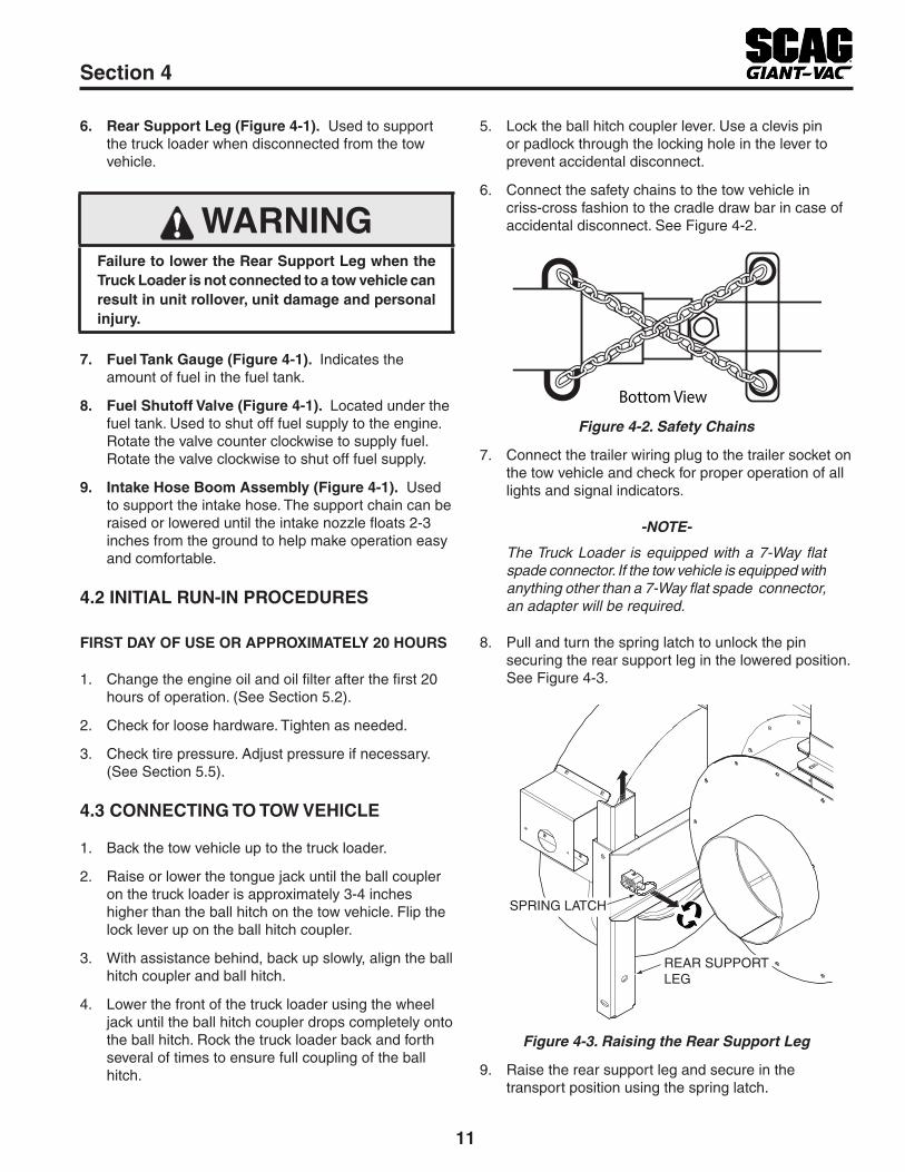
Connect the safety chains to the tow vehicle in 6. criss-cross fashion to the cradle draw bar in case of accidental disconnect. See Figure 4-2.
Bottom View
Safety ChainsFigure 4-2.
Connect the trailer wiring plug to the trailer socket on 7. the tow vehicle and check for proper operation of all lights and signal indicators.
-NOTe-
The Truck Loader is equipped with a 7-Way flat spade connector. If the tow vehicle is equipped with anything other than a 7-Way flat spade connector, an adapter will be required.
Pull and turn the spring latch to unlock the pin 8. securing the rear support leg in the lowered position. See Figure 4-3.
SPRING LATCH
REAR SUPPORTLEG
Raising the Rear Support LegFigure 4-3.
Raise the rear support leg and secure in the 9. transport position using the spring latch.
12
Section 4
STARTING THE ENGINE4.4
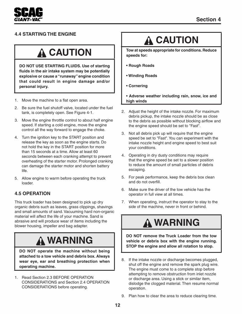
CAUTIONDO NOT USE STARTING FLUIDS. Use of starting fluids in the air intake system may be potentially explosive or cause a “runaway” engine condition that could result in engine damage and/or personal injury.
Move the machine to a flat open area.1.
Be sure the fuel shutoff valve, located under the fuel 2. tank, is completely open. See Figure 4-1.
Move the engine throttle control to about half engine 3. speed. If starting a cold engine, move the engine control all the way forward to engage the choke.
Turn the ignition key to the START position and 4. release the key as soon as the engine starts. Do not hold the key in the START position for more than 15 seconds at a time. Allow at least 60 seconds between each cranking attempt to prevent overheating of the starter motor. Prolonged cranking can damage the starter motor and shorten battery life.
Allow engine to warm before operating the truck 5. loader.
OPERATION4.5
This truck loader has been designed to pick up dry organic debris such as leaves, grass clippings, shavings and small amounts of sand. Vacuuming hard non-organic material will affect the life of your machine. Sand is abrasive and will produce wear of items including the blower housing, impeller and bag adapter.
WARNINGDO NOT operate the machine without being attached to a tow vehicle and debris box. Always wear eye, ear and breathing protection when operating machine.
Read Section 2.3 BEFORE OPERATION 1. CONSIDERATIONS and Section 2.4 OPERATION CONSIDERATIONS before operating.
CAUTIONTow at speeds appropriate for conditions. Reduce speeds for:
• Rough Roads
• Winding Roads
• Cornering
• Adverse weather including rain, snow, ice and high winds
Adjust the height of the intake nozzle. For maximum 2. debris pickup, the intake nozzle should be as close to the debris as possible without blocking airflow and the engine speed should be set to "Fast".
Not all debris pick up will require that the engine 3. speed be set to "Fast". You can experiment with the intake nozzle height and engine speed to best suit your conditions.
Operating in dry dusty conditions may require 4. that the engine speed be set to a slower position to reduce the amount of small particles of debris escaping.
For peak performance, keep the debris box clean 5. and do not overfill.
Make sure the driver of the tow vehicle has the 6. operator in full view at all times.
When operating, instruct the operator to stay to the 7. side of the machine, never in front or behind.
WARNINGDO NOT remove the Truck Loader from the tow vehicle or debris box with the engine running. STOP the engine and allow all rotation to stop.
If the intake nozzle or discharge becomes plugged, 8. shut off the engine and remove the spark plug wire. The engine must come to a complete stop before attempting to remove obstruction from inlet nozzle or discharge area. Using a stick or similar item, dislodge the clogged material. Then resume normal operation.
Plan how to clear the area to reduce clearing time.9.

13
Section 4
Collecting debris into piles for the machine to 10. intercept prior to start up will save time and fuel as well as wear and tear on the unit.
Keep the truck loader's intake nozzle and discharge 11. clean.
Use a slow travel speed when clearing heavy or 12. large amounts of material.
HILLSIDE OPERATION4.6
Slopes are a major factor related to loss-of-control and tip over accidents which can result in severe injury or death. All slopes require extra caution.
WARNINGDO NOT operate on steep slopes. Poor footing could cause a slip and fall accident. ALWAYS FOLLOW OSHA APPROvED OPERATION.
Do not operate on slopes if you are uneasy or 1. uncertain. Ultimate responsibility for safe operation on slopes rests with the operator.
Be sure of footing on slopes.2.
Caution must be used when operating on slopes, 3. especially when the grass is wet. Wet grass reduces traction and control.
To prevent tipping or loss of control, keep all 4. movements on slopes slow and gradual.
Do not turn on slopes unless necessary, and then 5. turn slowly and down hill when possible.
Do not start or stop on slopes. If tires lose traction, 6. stop the unit and proceed slowly straight down the slope.
Be alert for holes, rocks, roots, ruts and other hidden 7. hazards in the terrain. Uneven terrain could cause a slip and fall accident.
Do not operate near drop-offs, ditches, or 8. embankments. The operator could lose footing or balance or unit could suddenly turn over if a wheel is over the edge of a cliff or ditch, or if the edge caves in.
UNCOUPLING THE UNIT FROM THE TOW 4.7 vEHICLE
Park the machine on a flat, level surface only. Do not 1. park the machine on an incline.
Disconnect the trailer wiring plug from the tow 2. vehicle.
Unhook the safety chains from the rear of the tow 3. vehicle.
Unlock the ball hitch coupler lever on the unit and flip 4. up.
Crank down the tongue jack until the ball hitch 5. coupler on the unit clears the ball hitch on the tow vehicle.
Pull and turn the spring latch to unlock the pin 6. securing the rear support leg in the transport position. See Figure 4-4.
SPRING LATCH
REAR SUPPORTLEG
Lowering the Rear Support LegFigure 4-4.
Lower the rear support leg to the lowermost position 7. and secure with the spring latch.
WARNINGFaiure to lower the Rear Support Leg when the Truck Loader is not connected to a tow vehicle can result in unit rollover, unit damage and personal injury.
Block the wheels to prevent the machine from 8. moving. See Figure 4-5.

14
Section 4
Wheel ChocksFigure 4-5.
Pull the tow vehicle away.9.
AFTER OPERATION4.8
When machine is not in operation, in storage or 1. transporting, lock the hose support boom and secure hose on the storage pin. Pull and turn the spring latch to lock the pin securing the hose support boom in the transport position. See Figure 4-6 & Figure 4-7.
SPRING LATCH
HOSE SUPPORTBOOM
Locking the Hose Support BoomFigure 4-6.
HOSE STORAGEPIN
Hose Storage PinFigure 4-7.
After the engine has cooled down, wash the entire 2. machine after each use. Do not use high pressure spray or direct the spray onto electrical components.
- IMPORTANT -
Do not wash a hot or running engine. Cold water will damage the engine. Use compressed air to clean the engine if it is hot.
Keep the entire machine clean to inhibit serious heat 3. damage to the engine.
DANGERTo avoid injury from burns, allow the engine to cool before removing the fuel tank cap and refueling.
Check the tire pressure. Adjust pressure if 4. necessary.
15
Section 4
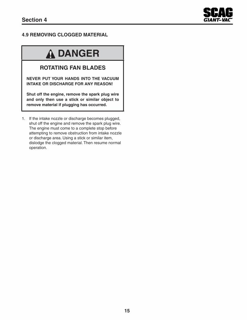
REMOvING CLOGGED MATERIAL4.9
DANGERROTATING FAN BLADES
NEvER PUT YOUR HANDS INTO THE vACUUM INTAKE OR DISCHARGE FOR ANY REASON!
Shut off the engine, remove the spark plug wire and only then use a stick or similar object to remove material if plugging has occurred.
If the intake nozzle or discharge becomes plugged, 1. shut off the engine and remove the spark plug wire. The engine must come to a complete stop before attempting to remove obstruction from intake nozzle or discharge area. Using a stick or similar item, dislodge the clogged material. Then resume normal operation.

16
Section 5
MAINTENANCE CHART - RECOMMENDED SERvICE INTERvALS5.1
HOURS
PROCEDURE COMMENTSBREAK-IN (FIRST 10)
8 20 50 100 200 500
X Check all hardware for tightness
X Check engine oil levelSee eng ine opera to r ' s manual
X *Clean truck loader
XCheck trailer lights for proper operation
C h e c k D a i l y b e f o r e operating
XCheck condition of impeller blades and impeller housing
X Change engine oil and filterSee eng ine opera to r ' s manual
X *Clean air filter elementSee eng ine opera to r ' s manual
X Check condition of fuel lines
X Check all hardware for tightness
X Change engine oilSee eng ine opera to r ' s manual
X *Clean air cleaner element See eng ine opera to r ' s manual
X *Clean Fuel CupSee eng ine opera to r ' s manual
X *Replace engine air filterSee eng ine opera to r ' s manual
X Clean and Adjust Spark PlugSee eng ine opera to r ' s manual
X Replace Spark PlugSee eng ine opera to r ' s manual
* Perform these maintenance procedures more frequently under extreme dusty or dirty conditions.
MAINTENANCE

17
Section 5
Never fuel the machine indoors or in an enclosed 4. trailer.
Never store the machine or fuel container where 5. there is an open flame, spark or pilot light such as on a water heater or other appliances.
Never fill containers inside a vehicle or on a truck 6. or trailer bed with a plastic liner. Always place containers on the ground away from your vehicle before filling.
Remove the machine from the truck or trailer and 7. fuel on level ground. If this is not possible, then refuel the machine with a portable container, rather than from a gasoline dispenser nozzle.
Keep the nozzle in contact with the rim of fuel tank 8. or container opening at all times until fueling is complete. Do not use a nozzle lock-open device.
If fuel is spilled on clothing, change clothing 9. immediately and wash affected skin.
Replace gas cap and tighten securely. 10.
ENGINE AIR CLEANER5.4
A. CLEANING AND/OR REPLACING AIR CLEANER ELEMENT
For any air cleaner, the operating environment dictates the air cleaner service periods. Inspect and clean the air cleaner element after every 50 hours of operation or monthly, whichever occurs first and replace the element if required or every 200 hours. Refer to the Engine Operator’s Manual furnished with this truck loader for instructions.
- NOTe -
In extremely dusty conditions it may be necessary to check the element once or twice daily to prevent engine damage.
WHEELS & TIRES5.5
Check the condition of wheel assemblies after 8 hours of operation or daily.
TRAILER LIGHTS5.6
Check the trailer lights for proper operation every day before operation. Replace any defective component before operating.
ENGINE OIL5.2
A. CHECKING ENGINE CRANKCASE OIL LEvEL
The engine oil level should be checked after every 8 hours of operation or daily as instructed in the Engine Operator’s Manual furnished with this truck loader.
B. CHANGING ENGINE CRANKCASE OIL
After the first 20 hours of operation, change the engine crankcase oil and replace the oil filter. Thereafter, change the engine crankcase oil after every 100 hours of operation or bi-weekly, whichever occurs first. Refer to the Engine Operator’s Manual furnished with this truck loader for instructions.
ENGINE FUEL SYSTEM5.3
DANGERTo avoid injury from burns, allow the engine to cool before removing the fuel tank cap and refueling.
A. FILLING THE FUEL TANK
Fill the fuel tank at the beginning of each operating day. Fill to the bottom of the filler neck insert (approximately 5-1/2 gallons indicating Full (F) on the fuel gauge) at the beginning of each operating day. Do not overfill. Use clean, fresh unleaded gasoline with a minimum octane rating of 87 and a maximum of 10% Ethanol.
DO NOT use E85 Fuel. Using E85 Fuel will cause severe damage to the engine.
To avoid personal injury or property damage, use extreme care in handling gasoline. Gasoline is extremely flammable and the vapors are explosive.
Extinguish all cigarettes, cigars, pipes and other 1. sources of ignition.
Use only an approved gasoline container.2.
Never remove the gas cap or add fuel with the 3. engine running. Allow the engine to completely cool before fueling.

18
Section 6
SCAG GIANT-vAC APPROvED ATTACHMENTS AND ACCESSORIES.6.1
Attachments and accessories manufactured by companies other than Scag Giant-Vac are not approved for use on this machine.
Scag Giant-Vac approved attachments and accessories:
Roadside Package (p/n 9xxx) - Includes Wheel Chocks, Wheel Chock Storage Boxes, Cones and • Cone Holder
Truck Loader Light Kit (p/n 9xxx)•
ILLUSTRATED PARTS LIST

19
Section 6
NOTES

20
Section 6
A
1
2
3
4
4
5
55
5
6
6
6
7
8
9
10
12
11
13
22
15
1416
17
1920
18
6
21
23
23
24
25
INTAKE AND DISCHARGE ASSEMBLY

21
Section 6
Ref. No.
Part No. Description
12345678910111213141516171819202122232425
484939-0348506045247904001-3204041-0704021-0946261742632745247748494748489448506548135-2845244004001-6304021-1042631246261248507548507604003-2342620948136-2304021-0804001-203
Hose, Metal Galv. Interlock 8" Dia. x 60"Clamp, Tube 8" Dia.Elbow, Exhaust - TL20WBolt, Hex Head 3/8-16 x 1-1/4"Flatwasher, 3/8-.391 X .938 X .105Nut, Elastic Stop 3/8-16Stack, Discharge w / Decals - TL20W (incl. #12)Bracket, License PlateWeldment, BoomDisk, Anti-FrictionChain w / 2-HooksSpring LatchHose, 12" O.D. x 120" - .045 w / WearstripBand, Hose SupportBolt, Hex Head 5/16-18 x 3-1/2"Nut, Elastic Stop 5/16-18Nozzle, 12"Handle Assembly w / Grips (incl. #19, 20)Grip, 1-1/4 x 6"Grip, 1-1/4 x 20"Bolt, Carriage 3/8-16 x 1"Bracket, Hose ProtectorClamp, 12" O.D.Nut, Elastci Stop 1/4-20Bolt, Hex Head 1/4-20 x 4"
INTAKE AND DISCHARGE ASSEMBLY
22
Section 6
B
B
1
23
4
54
4
6
7
88
821
20
9
10
1112
13
141516
17
17
18
18
19
20 21
8
4
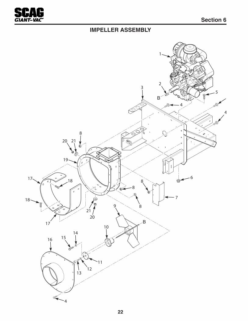
IMPELLER ASSEMBLY

23
Section 6
Ref. No.
Part No. Description
1
2345
678910111213141516171819202122
48495748500348500448500548495804063-3245243004017-2604001-1204001-1704019-0342620904019-0445245548482042613804030-0704015-2204030-0404001-2145247446258304014-0746260204020-0404041-04452501452520
Engine, 29HP Briggs & Stratton Vanguard (not available through Scag Giant-Vac)Muffler, 29hp Briggs & Stratton (not shown)Exhaust Manifold, 29hp Briggs & Stratton (not shown)Wire Guard, 29hp Briggs & Stratton (not shown)Engine, 26.5hp Kohler EFI (not available through Scag Giant-Vac)Key, 3/8 x 3/8 x 3-1/2"Base & Frame Weldment w / DecalsBolt, Hex Head Serrated Flange 3/8-16 x 3/4"Bolt, Hex Head 5/16-18 x 1-3/4"Bolt, Hex Head 5/16-18 x 2" (LH Front)Nut, Serrated Flange 5/16-18Bracket, Hose ProtectorNut, Serrated Flange 3/8-16Impeller Weldment, TL20WHub, Tapered Locking Q2 x 1-7/16"Cover Plate, Hub Taper - TL20WLockwasher, 5/8"Socket Head Cap Screw, 5/8-18 x 1-3/4"Lockwasher, 3/8"Bolt, Hex Head 3/8-16 x 1-3/4"Cover, Housing - TL20WWearliner Kit w/ HardwareCapscrew, 3/8-16 x 1-1/4"Housing Weldment w / DecalsNut, 3/8-16Flatwasher, 1/2-.516 x .938 x 12 Ga.Weldment, Exhaust Deflector - 29hp Briggs & StrattonWeldment, Exhaust Deflector - 26.5hp Kohler EFI
IMPELLER ASSEMBLY

24
Section 6
TRAILER ASSEMBLY
11
23
412
41
2
3
5
4
24
5
4
9
9
9
12
10
1119
24
42
13
14
15
16
16
16
20
21
2242
28
1718
25
1718
26 27
16
16
2942
1718
230
31
1817
33
7
6
34
3536
37
12
38
39
8
40
4232

25
Section 6
Ref. No.
Part No. Description
1
234567891011121314151617181920212223242526
27282930313233343536373839404142
48507848510504040-0704001-3704021-0748506448484904001-1946261648499048505304003-3904021-0804001-7042620742632604003-2304041-0704021-0948506248505045241304001-11904001-20404021-2345249048494848509148509204028-0204019-0648478304001-7145248948508042620804001-14504021-0745248804003-3904019-0242629348511004043-0904040-14
Ball Hitch, 2"Pintle Hitch (optional)Flatwasher, 1/2-.531 x 1.062 x .095Bolt, Hex Head 1/2-13 x 5-1/2"Nut, Elastic Stop 1/2-13Safety Chain, 5/16 x 36"Jack, Single Wheel Stow AwayBolt, Hex Head 3/8-16 x 1"Draw Bar w / DecalsBattery Box w / StrapSpacer, Battery BoxBolt, Hex Head 1/4-20 x 6"Nut, Elastic Stop 1/4-20Bolt, Hex Head 1/2-13 x 1-1/4"Fuel Tank MountBracket, Canister MountBolt, Carriage 3/8-16 x 1"Flatwasher, 3/8-.391 x .938 x .105Nut, Elastic Stop 3/8-16Quick Pin Assembly w / LanyardWasher, RubberWeldment, Hose HolderBolt, Hex Head 5/8-11 x 5-1/2"Bolt, Hex Head 5/8-11 x 4-3/4" Grade 8Nut, Center Lock 5/8-11Fender Weldment, RHWheel Assembly, 205 / 75-D15 (6-Ply)Rim, 15 x 5Tire, 205 / 75-D15 (6-Ply)Nut, Lug 1/2-20 UNFNut, Serrated Flange 1/2-13Axle, 2000 LBS - 5 Lug, 47"Bolt, Hex Head 1/2-13 x 1-1/2"Fender Weldment, LHGrommet, RubberSupport Channel, TL20WBolt, Hex Head 1/2-13 x 3-1/2"Nut, Elastic Stop 1/2-13Ball Hitch MountBolt, Carriage 1/4-20 x 1-1/4"Nut, Serrated Flange 1/4-20Plate, SpacerPin, SnapFlatwasher, 5/8-.656 x 1.312 x .095 HardenedFlatwasher, 1/4-.312 x .750 x .065
TRAILER ASSEMBLY

26
Section 6
FUEL SYSTEM
2014 TL20W Fuel System
To Fuel Pump
To Engine Purge Port
Tank
Purge
A
AB
B
3
2
1
4
5
6
7 8*9
*10
*10
*11
15
16
17
18
19
19
20
12
1321
22
20
23
28
24
25
26
27
22
22
22
23
3113
14
7
29
30

27
Section 6
Ref. No.
Part No. Description
12345678910111213141516171819202122232425262728293031
46261148428648425948424248257148374748059-01483617***48434704030-0304001-08484287484285484333484343-0148030-2248434504001-0848059--0548059-0204019-0342632648136-1704003-04484279-0104001-7004019-0604040-15
Fuel Tank, TL20WFuel Cap, TetheredFuel Gauge Assembly, 11 (incl. #4)Seal, Fuel GaugeBushing, 0.56 Dia. VitonFuel Shutoff Valve w / ScreenClamp, Fuel Hose 1/4" I.D.Hose, Fuel Line 1/4" (order by inch)Fuel Filter (contact engine manufacturer)Clamp (contact engine manufacturer)Fuel Hose (contact engine manufacturer)Hose, Vapor Recovery 1/4" (order by the inch)Lockwasher, 5/16"Bolt, Hex Head 5/16-18 x 3/4"Carbon Canister, 400ccGrommet, VitonRemote VentMender, 1/4 x 3/16 w / 0.02 HoleClamp, 3/8"Hose, Vapor Recovery 3/16" (order by inch)Bolt, Hex Head 5/16-18 x 3/4"Clamp, Vapor Recovery 3/16"Clamp, Fuel Hose 7/32" O.D.Nut, Serrated Flange 5/16-18Bracket, Canister MountClampBolt, Carriage 5/16-18 x 1"Tube, Fuel Tank InsertBolt, Hex Head 1/2-13 x 1-1/4"Nut, Serrated Flange 1/2-13Flatwasher, 5/16-.375 x .875 x .083
FUEL SYSTEM

28
Section 6
GROUND (BLACK)TO ENGINE POSITIVE (RED)
TO ENGINE STARTER
1
1
2
2
3 3
416 15
5
8
6
7
8
9
7
1011
13
11
13
108
7
9
96
8
1412
8
ELECTRICAL SYSTEM

29
Section 6
Ref. No.
Part No. Description
12345678910111213141516
48499004020-0204001-06*48504348504104011-2348511248504048507248503948507748511104011-0648029-1348029-11
Battery Box w / StrapNut, 1/4-20Bolt, Hex Head 1/4-20 x 0.63Battery (not available through Scag Giant-Vac)Wire Harness, TL20W (incl. #8, 13, 15)Side Marker Light, YellowScrew, #8-18 x 3/4" Self TapWire Harness Adapter, Side Marker Light - ShortSide Marker Light, RedGrommet, Tail LightStop / Turn / Tail LightLight, License PlateWire Harness Adapter, Tail LightScrew, #10-32 x 3/4" Self TapBattery Cable, Red 25"Battery Cable, Black 27"
ELECTRICAL SYSTEM
30
Section 6
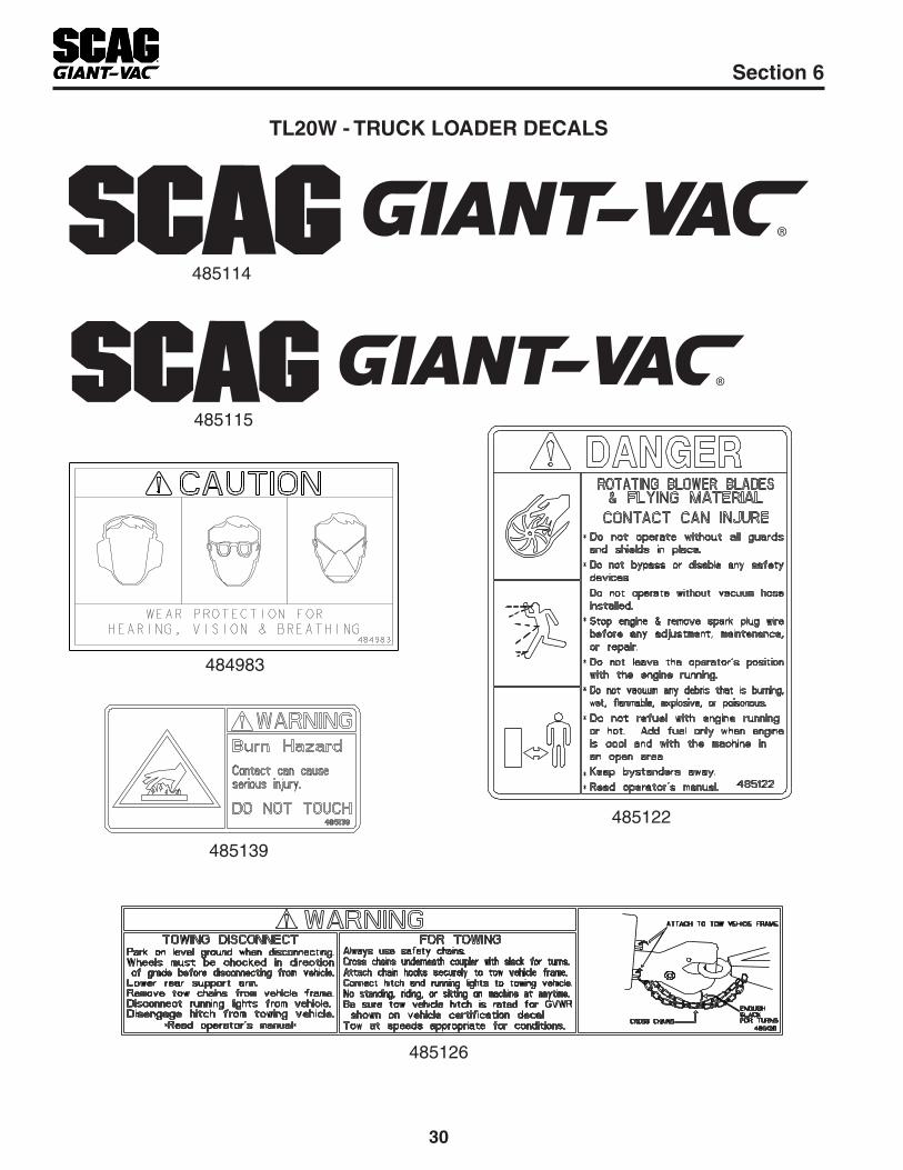
485114
TL20W - TRUCK LOADER DECALS
485115
484983
485122
485126
485139

31
Section 6
TL20W - TRAILER LIGHT WIRING DIAGRAM
L.H. TAIL LIGHTR.H. TAIL LIGHT
R.H. REAR SIDEMARKER LIGHT
L.H. REAR SIDEMARKER LIGHT
R.H. FRONT SIDEMARKER LIGHT
L.H. FRONT SIDEMARKER LIGHT
LICENSE PLATE LIGHT
TOW VEHICLECONNECTOR
L.H. TAIL LIGHTR.H. TAIL LIGHT
R.H. REAR SIDEMARKER LIGHT
L.H. REAR SIDEMARKER LIGHT
R.H. FRONT SIDEMARKER LIGHT
L.H. FRONT SIDEMARKER LIGHT
LICENSE PLATE LIGHT
TOW VEHICLECONNECTOR
RED
WHITE
BLACK
RED W/WHITE STRIPE
GREENYELLOW
WHITE
BROWNBROWN
BR
OW
N
BR
OW
N
BR
OW
N
WH
ITE
WH
ITE
WH
ITE
WH
ITE
WH
ITE
YE
LLOW
GR
EE
N
BR
OW
NB
RO
WN
WHITEWHITE
BLACK
RE
D W
/WH
ITE
ST
RIP
E
RE
D
BLA
CK
BLA
CK
WH
ITE
WH
ITE
SERIAL NUMBER RANGETL20W-26CH-EFI (010A00001 to 010A00012)TL20W-29BV (009A00001 to 009A00060)TLB25-35BV (011A00001 to 011A00016)TLB25-37CH (012A00001 to 012A00008)TLB25-48KBD (013A00001 to 013A00006)
SERIAL NUMBER RANGETL20W-26CH-EFI (010A00013 & Higher)TL20W-29BV (009A00061 & Higher)TLB25-35BV (011A00017 & Higher)TLB25-37CH (012A00009 & Higher)TLB25-48KBD (013A00009 & Higher)

LIMITED WARRANTY - TRUCK LOADERSAny part of the Truck Loader manufactured by Scag Giant-Vac and found, in the reasonable judgment of Scag Giant-Vac, to be defective in materials or workmanship, will be repaired or replaced by an Authorized Scag Giant-Vac Service Dealer without charge for parts and labor during the periods specified below. This warranty is limited to the original purchaser and is not transferable. Proof of purchase will be required by the dealer to substantiate any warranty claims. All warranty work must be performed by an Authorized Scag Giant-Vac Service Dealer.
This warranty is limited to the following specified periods from the date of the original retail purchase for defects in materials or workmanship:
Wear items including impellers, wear liners, nose cones, hoses, bearings and tires are not included in this warranty.•Frame, blower housing and structural components are warranted for two (2) year (parts and labor) for commercial and •
non-commercial use.Engines and electric starters are covered by the engine manufacturer’s warranty period. Therefore, there are no warranties made, •
expressed or implied, for engines by Scag Giant-Vac.Batteries are covered for ninety (90) days.•Any Scag Giant-Vac product used for rental purposes is covered by a 90 day warranty. •
The Scag Giant-Vac Truck Loader, including any defective part must be returned to an Authorized Scag Giant-Vac Service Dealer within the warranty period. The expense of delivering the truck loader to the dealer for warranty work and the expense of returning it to the owner after repair will be paid for by the owner. Scag Giant-Vac’s responsibility is limited to making the required repairs and no claim of breach of warranty shall be cause for cancellation or rescission of the contract of sale of any Scag Giant-Vac product. “Non-Commercial” use is defined as a single property owner, where the single property is the residence of the owner of the Scag Giant-Vac product. If the truck loader is used on more than the owners single property, it is deemed commercial use and the “non-commercial” warranty does not apply. Scag Giant-Vac reserves the right to deny and / or void the non-commercial warranty if it believes it to be in commercial use.
This warranty does not cover any product that has been subject to misuse, neglect, negligence, or accident, or that has been operated in any way contrary to the operating instructions as specified in the Operator’s Manual. The warranty does not apply to any damage to any truck loader that is the result of improper maintenance, or to any truck loader or parts that have not been assembled or installed as specified in the Operator’s Manual and Assembly Manual. The warranty does not cover any truck loader that has been altered or modified, changing performance or durability. In addition, the warranty does not extend to repairs made necessary by normal wear, to items subject to abrasion wear, or by the use of parts or accessories which, in the reasonable judgment of Scag Giant-Vac, are either incompatible with the Scag Giant-Vac Truck Loader or adversely affect its operation, performance or durability.
Scag Giant-vac reserves the right to change or improve the design of any product without assuming any obligation to modify any product previously manufactured. All other implied warranties for truck loader are limited in duration to the two (2) year warranty for commercial and non-commercial use or ninety (90) days used for rental purpose. Accordingly, any such implied warranties including merchantability, fitness for a particular purpose, or otherwise, are disclaimed in their entirety after the expiration of the appropriate warranty period. Scag Giant-Vac’s obligation under this warranty is strictly and exclusively limited to the repair or replacement of defective parts and Scag Giant-Vac does not assume or authorize anyone to assume for them any other obligation. Some states do not allow limitations on how long an implied warranty lasts, so the above limitation may not apply to you.
Scag Giant-Vac assumes no responsibility for incidental, consequential or other damages including, but not limited to, expense for gasoline, expense of delivering the truck loader to an Authorized Scag Giant-Vac Service Dealer and expense of returning it to the owner, mechanic’s travel time, telephone or telegram charges, rental of a like product during the time warranty repairs are being performed, travel, loss or damage to personal property, loss of revenue, loss of use of the truck loader, loss of time or inconvenience. Some states do not allow the exclusion or limitation of incidental or consequential damages, so the above limitation or exclusion may not apply to you. This warranty gives you specific legal rights, and you may also have other rights which vary from state to state.