operators manuel international cub cadet 72, 104, 105, 124, znd 125 tractors
DESCRIPTION
Operators Manuel International Cub Cadet 72, 104, 105, 124, znd 125 tractorsTRANSCRIPT

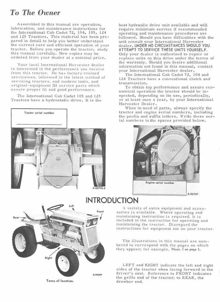
INTRODUCTION
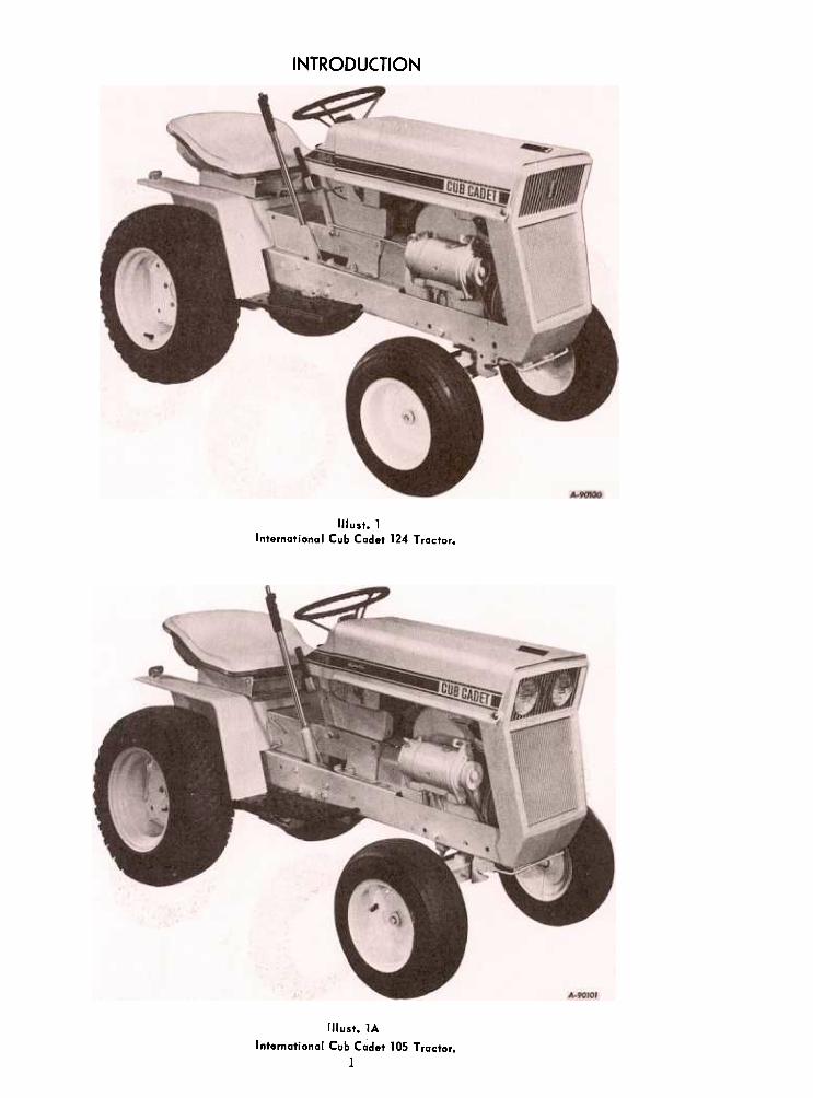
Illust. 1International Cub Cadet 124 Tractor.
(Ilust. 1A
International Cub Cadet 105 Tractor.
1
INTRODUCTION
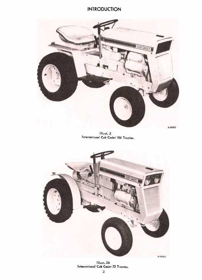
Illust.2Internatianal Cub Cadet 104 Tractor.
Illust. 2AInternatianal Cub Cadet 72 Tractar.
2
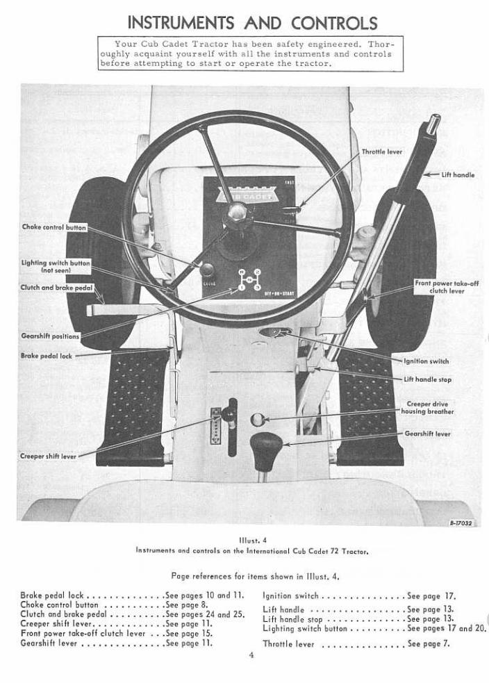


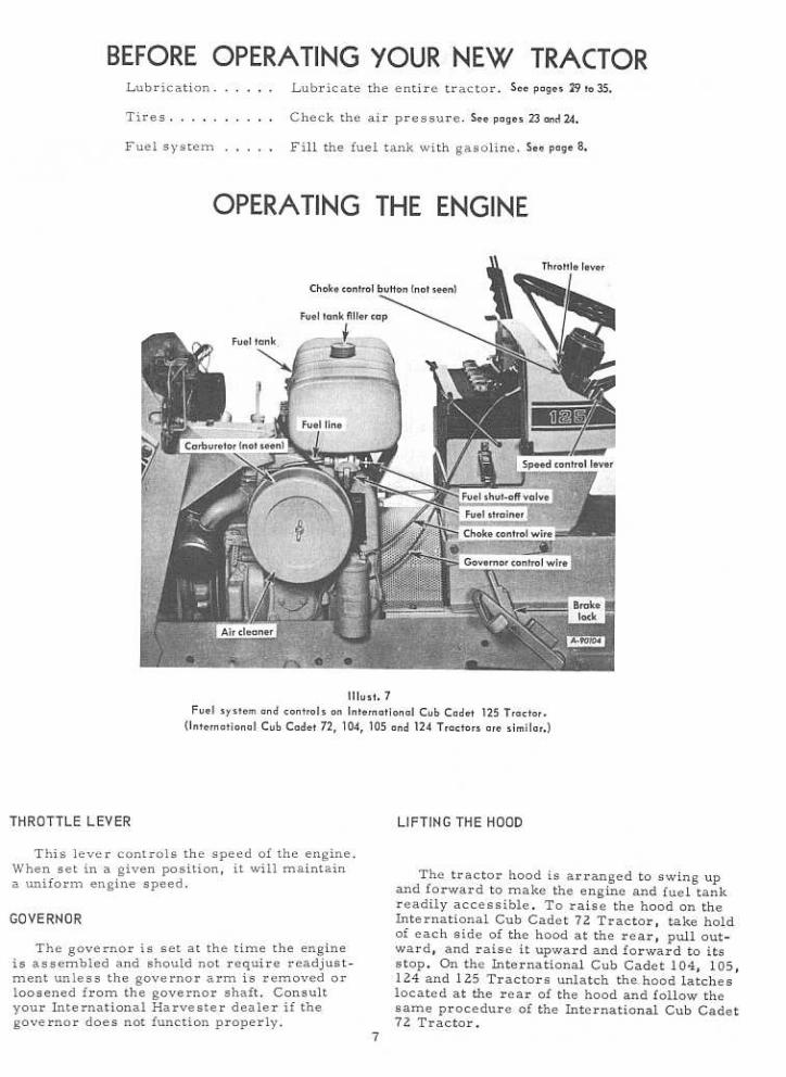
OPERATING THE ENGINE
STARTING THE ENGINE
Be sure the fuel shut-off valve is open.
control button all the way in. Do not use thechoke to enrich the fuel mixture, except whennecessary to start the engine.
Manual Starting '(Tractors without electric storting):Raise the tractor hood. The retractable starteris mounted on a support plate at the front of theengin~ at the right side of the tr actor.
2. Pull the choke control button all the wayout (see Illust.4or5}. More or less choking may benecessary due to variations in temperature,grade of fuel, etc. Little or none will beneeded when the engine is warm.
Put the gearshift lever in the neutral posi-tion and lock the brake. Turn the key ignitionswitch clockwise.
Give a quick steady pull on the retractablestarter handle to start the engine. Do not jerk,or pull it out to its very end in a rough manner.A steady pull will accomplish just as much.Always pull the handle so the cord is in astraight line through the guide. Maintain yourhold on the handle and allow the cord to returl}slowly. Releasing the handle when the cable isextended will shorten the life of the starter.
3. Place the throttle lever halfway between"SLOW" and "FAST". See Illust. 4 or 5.
4. Electric Starting: The engine cannot bestarted unless the brake pedal is pressed allthe way down to activate the safety startingswitch.
International Cub Cadet 72, 104, and 1'24 Tractors:Check to see that the gearshift lever is in theneutral position. See Illust. 4.
International Cub Cadet 105 and 125 Tractors:Check to see that the speed control lever is inth " N " ot O Se pOSI Ions. ee Illust. 6. 5. After the engine starts, slowly release
the clutch pedal and gradually push the chokecontrol button all the way in. Do not use thechoke to enrich the fuel mixture, except whennecessary to start the engine.
STOPPING THE ENGINE
All Models: Turn the ignition key clockwiseto the "START" position and release it as soonas the engine starts; however do not operate themotor-generator for more than 30 seconds atanyone time. If the engine does not start withinthis time, turn the key "OFF" and wait a fewminutes, then try again. Move the throttle lever to the "SLOW" po-
sition and allow the engine to idle for a shorttime before stopping. Then turn the key to the"OFF" position.
5. After the engine starts, slowly releasethe brake pedal and gradually push the choke
FUEL SHUT.OFF VALVEFUEL SYSTEM
Be sure the shut-off valve on the fuelstrainer under the gasoline tank is open.Screw out the needle stem (Shut-off valve) un-til the seat on the stem is tight against thestop, to prevent leakage or seepage when thevalve is in its full-open position.
Fill the fuel tank with clean, fresh, regulargrade gasoline, preferably at the end of eachday's use. This will force out any moisture-laden air and prevent condensation in the fueltank. Do not mix oil with the gasoline.
CLEANING THE FUEL STRAINER AND SEDIMENT BOWLThe fuel tank filler cap has an ai.r vent.Keep the vent open at all times to assureproper flow of the fuel. After every 25 hours of operation, clean
the fuel strainer as follows:
Caution! Never remove the fuel tank capor fill the fuel tank when the engine is running,is hot, or when near an open flame. Do notsmoke when working around inflammable fuel,as the air around the tractor is mixed with ahighly explosive vapor. When pouring fuel,keep the container or hose nozzle in contactwith the metal of the fuel tank to avoid thepossibility of an electric spark igniting thega s. Do not spill ga s oline on a hot engine.
1. Close the shut-off valve. See Illusts. 9 and 9A.Loosen the knurled nut under the sedimentbowl and remove the bowl and screen.
2. Clean the sediment bowl and screen.
3. When reassembling, be sure the gasketbetween the bowl and the main body is in goodcondition and does not leak. Use a new gasketif necessary.
8
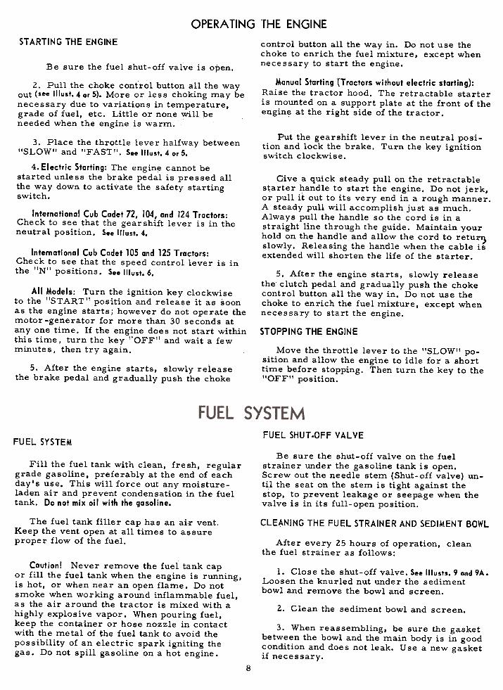
FUEL SYSTEM
Illust.9Carburetor and fuel strainer.
(International Cub Cadet 72 Tractor)
(1Iust.9ACarburetar and fuel strainer.
(International Cub Cadet 104, 105, 124 and 125 Tractars)
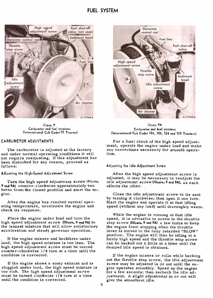
CARBURETOR ADJUSTMENTS For a final check of the high speed adjust-ment, operate the engine under load and makeany corrections necessary for smooth opera-tion.
Adjusting the Idle Adjustment Screw
The carburetor is adjusted at the factoryand under normal operating conditions it willnot require readjusting. If this adjustment hasbeen disturbed for any reason, proceed asfollows:
Adjusting the High-Speed Adjustment Screw After the high speed adjustment screw isadjusted, it may be necessary to readjust theidle. adjustment screw (1IIusts. 9 and 9A), as eachaffects the other..
Turn the high speed adjustment screw (1IIusts.9 and 9A) counter-clockwise approximately twoturns from the closed position and start the en-gine.
Close the idle adjustment screw to its seatby turning it clockwise; then open it one turn.Start the engine and operate it at fast idlingspeed (without any load) until thoroughly warm.
After the engine has reached normal oper~ating temperature, accelerate the engine andcheck its response.
While the engine is running at fast idlespeed, it is advisable to screw in the throttlestop screw (1IIusts. 9 and 9A) a few turns to keepthe engine from stopping when the throttlelever is moved to the fully retarded "SLOW"position. The engine will then be idling at afairly high speed and the throttle stop screwcan be backed out a little at a time until thedesired idle speed is obtained.
Place the engine under load and turn thehigh speed adjustment screw (1III/sts. 9 and 9A) tothe leanest mixture that will allow satisfactoryacceleration and steady governor operation.
If the engine misses and backfires underload, the high speed mixture is too lean. Thehigh speed adjustment screw must be turnedcounter-clockwise l/4 turn at a time until thecondition is corrected. If the engine mis'ses or rolls while backing
out the throttle stop screw, the idle adjustmentscrew may be adjusted in or out until the en-gine operates smoothly. Speed up the enginefor a few seconds; then recheck the idle ad-justment. A slight adjustment in or out willgive the smoothest idle.
If the engine shows a sooty exhaust and issluggish under load, the high speed mixture istoo rich. The high speed adjustment screwmust be turned clockwise 1/4 turn at a timeuntil the condition is corrected.
9
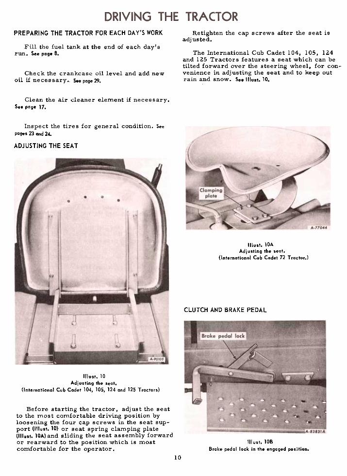
PREPARING THE TRACTOR FOR EACH DAY'S WORK Retighten the cap screws after the seat isadjusted.
Fill the fuel tank at the end of each day'srun. See page 8. The International Cub Cadet 104, lOS, 124
and 125 Tractors features a seat which can betilted forward over the steering wheel, for con-venience in adjusting the seat and to keep outrain and snow. See Illust. 10.
Check the crankcase oil level and add newoil if ne ce s s ary. See page 29.
Clean the air cleaner element if necessary.See page 17.
Inspect the tires for general condition. Seepages 23 and 24-
ADJUSTING THE SEAT
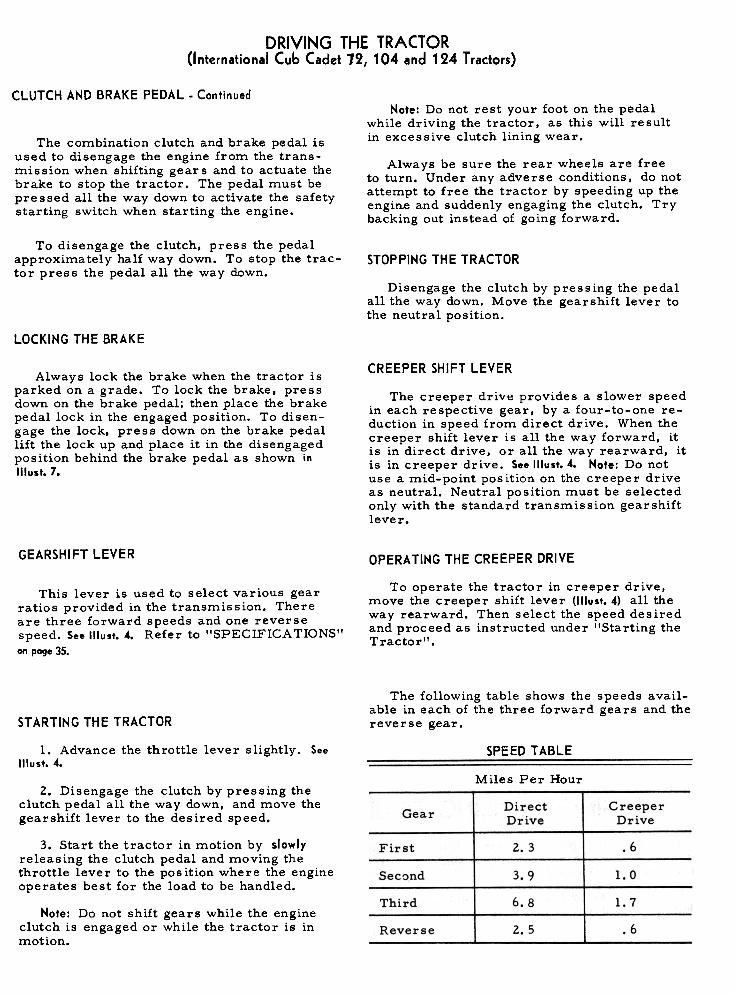
Illust. lOAAdjusting the seat.
(Internatianal Cub Cadet 72 T ractar.)
CLUTCH AND BRAKE PEDAL
Illust. 10Adj usting the seat.
(Internatianal Cub Cadet 104, 105, 124 and 125 Tractars)
Before starting the tractor, adjust the seatto the most comfortable driving position byloosening the four cap screws in the seat sup-port (lllust. 10) or seat spring clamping plate(lllust. lOA) and sliding the seat assembly forwardor rearward to the position which is mostcomfortable for the operator.
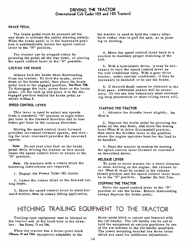
III ust. lOB
Brake pedal lack in the engaged position.
10
DRIVING THE TRACTOR(I nternational Cub Cadet 12, 104 and 124 Tractors)
CLUTCH AND BRAKE PEDAL. ContinuedNote: Do not rest your foot on the pedal
while driving the tractor, as this will resultin excessive clutch lining wear.The combination clutch and brake pedal is
used to disengage the engine from the trans-mission when shifting gears and to actuate thebrake to stop the tractor. The pedal must bepressed all the way down to activate the safetystarting switch when starting the engine.
Always be sure the rear wheels are freeto turn. Under any adverse conditions, do notattempt to free the tractor by speeding up theengine and suddenly engaging the clutch. Trybacking out instead of going forward.
To disengage the clutch, press the pedalapproximately half way down. To stop the trac-tor press the pedal all the way down.
STOPPING THE TRACTOR
Disengage the clutch by pressing the pedalall the way down. Move the gearshift lever tothe neutral position.
LOCKING THE BRAKE
CREEPER SHIFT LEVERAlways lock the brake when the tractor is
parked on a grade. To lock the brake, pressdown on the brake pedal; then place the brakepedal lock in the engaged position. To disen-gage the lock, press down on the brake pedallift the lock up and place it in the disengagedposition behind the brake pedal as shown inIllust. 7.
The creeper drive provides a slower speedin each respective gear, by a four-to-one re-duction in speed from direct drive. When thecreeper shift lever is all the way forward, itis in direct drive, or all the way rearward, itis in creeper drive. See 1(lust. 4. Note: Do notuse a mid-point position on the creeper driveas neutral. Neutral position must be selectedonly with the standard transmission gearshiftlever.
GEARSHIFT LEVER OPERATING THE CREEPER DRIVE
To operate the tractor in creeper drive,move the creeper shift lever (1IIust.4) all theway rearward. Then select the speed desiredand proceed as instructed under !'Starting theTractor".
This lever is used to select various gearratios provided in the transmission. Thereare three forward speeds and one reversespeed. See Illust. 4. Refer to "SPECIFICA TlaNS"on page 35.
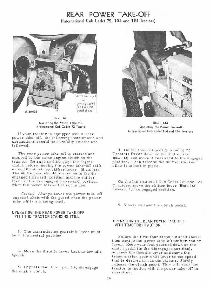
The following table shows the speeds avail-able in each of the three forward gears and thereverse
gear.STARTING THE TRACTOR
SPEED TABLE1. Advance the throttle lever slightly. SeeIllust. 4.
Miles Per Hour2. Disengage the clutch by pressing the
clutch pedal all the way down. and move thegearshift lever to the desired speed.
CreeperDrive
DirectDriveGear
.62.3First3. Start the tractor in motion by slowlyreleasing the clutch pedal and moving thethrottle lever to the pos ition where the engineoperates best for the load to be handled.
1.0Sec~nd 3.9
Third 6.8 1.7Note: Do not shift gears while the engine
clutch is engaged or while the tractor is inmotion.
2.5 .6
Reverse
DRIVING THE TRACTOR(International Cub Cadet 105 and 125 Tractors)
BRAKE PEDAL
the tractor is used to hold the rotary tillerback rather than to pull the unit, as in plow-ing or mowing.
The brake pedal must be pressed all theway down to activate the safety starting switch.When the brake pedal is in the depressed posi-tion it automatically moves the speed controllever to the "Nil position.
4. Move the speed control lever back to aposition to maintain proper mulching of thesoil.
The tractor can be stopped either bypressing the pedal all the way down, or placingthe speed control lever in the I'NII position.
5. With a hydrostatic drive, it may be nec-essary to vary the speed control lever asthe soil conditions vary. With a gear drivetractor, under similar conditions, it may benecessary to de clutch or to use the brake.
LOCKING THE BRAKE
Always lock the brake when dismountingfrom the tractor. To lock the brake, pressdown on the brake pedal; .then place the brakepedal lock in the engaged position. S..lllust. 10B.To disengage the lock, press down on the brakepedal, lift the lock up and place it in the dis-engaged position behind the brake pedal asshown in Illust. 7.
6. If desired depth cannot be obtained in thefirst pass. additional passes will be neces-sary. Do not use tine extensions when attempt-ing deep penetration or when tilling heavy soil.
SPEED CONTROL LEVER
This lever is used to select any speedsfrom a standstill IINII position to eight milesper hour in the forward direction and to fourmiles per hour in the reverse direction.
STARTING THE TRACTOR1. Advance the throttle lever slightly. See
1!lust.6.
2. Dep~ess the brake pedal by pressing thepedal all the way down, and move the towinglever (I'luit. 6) in drive (horizontal) position,then move the throttle lever to the positionwhere the engine operates best for the load tobe handled.
Moving the speed control lever forwardprovides increased forward speeds. and mov -ing the lever rearward provides the reversedspeeds.
Note: Do not rest your foot on the brakepedal while driving the tractor as this wouldcause the speed control lever to return to the!'N'I position.
Note: On tractors with a rotary tiller thefollowing instructions are required.
1. Engage the Power Take- Off clutch.
2. Lower the rotary tiller to the desired cut-ting depth.
3. Start the tractor in motion by movingthe speed control lever forward or rearwardas described above.
RELEASE LEVERTo push or move tractor for a short distance
or when working on the engine, the release le-ver (1IIust.6) must be locked in the release(down) position and the speed control lever mustbe in the "N" position. Caution: Do Not Tow.
STOPPING THE TRACTORMove the speed control lever to the I'NI'
position or use the brake. Before dismountingalways depress the brake pedal.
3. Move the speed control lever to start for-ward motion. Note: In rotary tilling application,
three-point hitch is raised and lowered withthe lift handle. The lift handle can be set tohold the equipment at various positions by useof the six notches in the lift handle quadrant.The lower mounting bracket has three holeswhich are used for additional adjustment.
Trailing-type equipment must be hitched tothe tractor only at the hitch hole in the draw-bar. See Illusts. 13 and 13A.
When the tractor has a three-point hitch(1IIusts. 13 and 13A) equipment adaptable to the
12

OPERATING THE FRONT POWER TAKE-OFF CLUTCH
1. Move the throttle lever back to mediumor low idle speed.
The clutch is factory adjusted and shouldnot require further adjustment under normaloperating conditions. However, if clutchslippage should occur. It is recommendedthat you see your International Harvesterdealer for satisfactory servicing of the clutch,as special equipment and instructions arerequired.
2. Move the front power take-off clutchlever (forward) to the engaged position.(rearward) to the disengaged position. See'"usts. 4 or S.
After considerable clutch use, it may benecessary to readjust the button clearance asdescribed below to assure proper clutch dis-engagement.
Hote: It is recommended that the clutchlever be placed in the forward or engagedposition when the tractor is being used with-out front power take -off equipment.
ADJUSTING THE CLUTCH
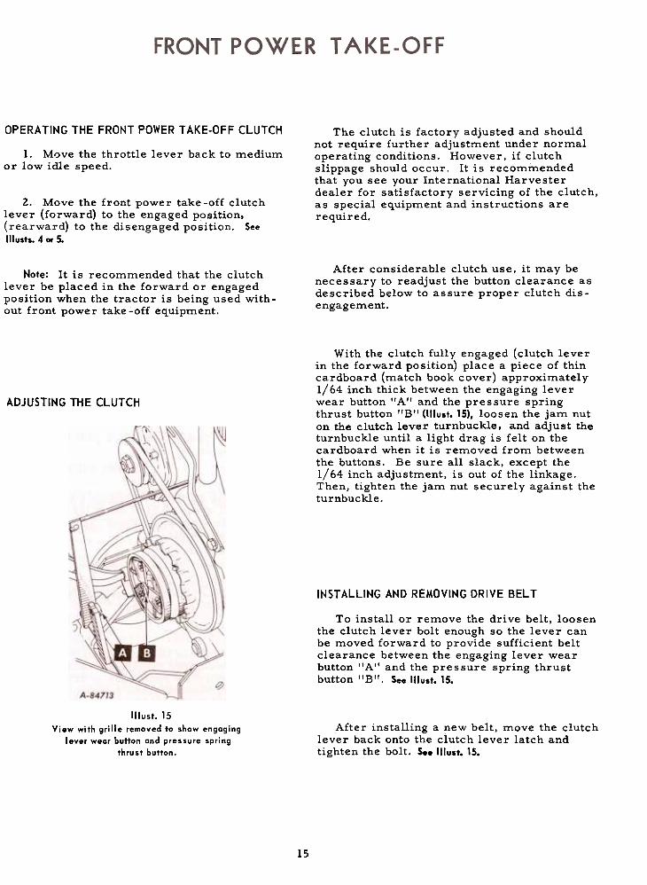
With the clutch fully engaged (clutch leverin the forward position) place a piece of thincardboard (match book cover) approximately1/64 inch thick between the engaging leverwear button I'A'I and the pressure springthrust button "B'I (1IIust. 15), loosen the jam nuton the clutch lever turnbuckle, and adjust theturnbuckle until a light drag is felt on thecardboard when it is removed from betweenthe buttons. Be sure all slack, except the1/64 inch adjustment, is out of the linkage.Then, tighten the jam nut securely against theturnbuckle.
It~ST ALLING AND REMOVING DRIVE BELT
To install or remove the drive belt, loosenthe clutch lever bolt enough so the lever can
be moved forward to provide sufficient beltclearance between the engaging lever wearbutton IIAII and the pressure spring thrustbutton IIBII. See Illust. 15.
After installing a new belt, move the clutchlever back onto the clutch lever latch andtighten the bolt. See ttlust. 15.
Illust. 15
View with grille removed to show engoginglever wear button and pressure spring
thrust button.
15
UNIT
Note: A slightly sluggish action of the con-trollever returning to neutral may exist duringthe break-in period. A few hours of runningwill eliminate this. No adjustments are neces-sary.
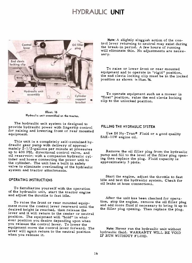
To raise or lower front or rear mountedequipment and to operate in "rigid ,. position,the end clevis locking clip must be in the lockedposition as shown in Illust. 16.
To operate equipment such as a mower in"float" position, raise the end clevis lockingclip to the unlocked position.
Illust. 16Hydraulic unit assembled on the tractor.
The hydraulic unit system is designed toprovide hydraulic power with fingertip controlfor raising and lowering front or rear mountedequipment.
FILLING THE HYDRAULIC SYSTEM
Use IH Hy-Tranle> Fluid or a good qualitySAE -I OW engine oil.
This unit is a completely self-contained hy-draulic gear pump with delivery of approxi-mately 2-l/2-gallons per minute at pressuresup to 400 PSI, directional control valve, andoil reservoir; with a companion hydraulic cyl-inder and hoses connecting the power unit tothe cylinder. The unit has a built in safetyvalve to eliminate overloading of the hydraulicsystem and tractor attachments.
Remove the oil filler plug from the hydraulicpump and fill to the level of the filler plug open-ing then replace the plug. Fluid capacity isapproximately 3 pints.
Start the engine. adjust the throttle to fastidle and test the hydraulic system. Check foroil leaks at hose connections.
OPERATING INSTRUCTIONS
To familiarize yourself with the operationof the hydraulic unit. start the tractor engineand adjust the throttle to fast idle.
After the unit has been checked for opera-tion, stop the engine, remove the oil filler plugand add more fluid if necessary to bring it up tothe filler plug opening. Then replace the plug.
To raise the front or rear mounted equip-ment move the control lever rearward until thedesired height is reached, then release thelever and it will return to the center or neutralposition. The equipment will "hold" in what-ever position you desire depending upon whenyou release the control lever. To lower theequipment move the control lever forward. Thelever will again return to the neutral positionwhen you release it.
Note: Never run the hydraulic unit withouthydraulic fluid. WARRANTY WILL BE VOIDIF RUN WITHOUT FLUID.
16
~
ENGINE COOLING
This tractor has an air cooled engine. Airmust be able to circulate freely around theengine, through the screen and shroud, andover the fins of the cylinder head and cylinderblock.
Keep these areas free of accumulateddirt and trash or the engine will overheat andresult in damaged moving parts.
DRY-TYPE AIR CLEANER
Incoming air for combustion is filtered bya dry-type air cleaner having a filter elementinside of the cover.
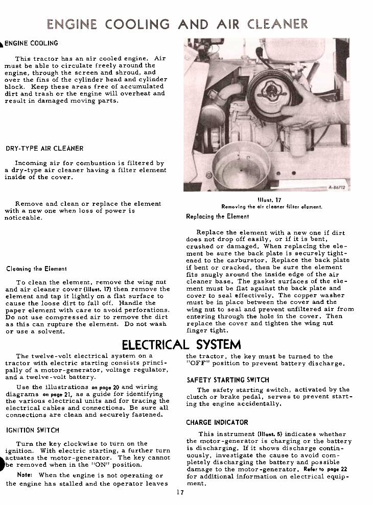
Remove and clean or replace the elementwith a new one when loss of power isnoticeable.
Illust. 17Removing the air cleaner filter element.
Replacing the Element
Replace the element with a new one if dirtdoes not drop off easily, or if it is bent,crushed or damaged. When replacing the ele-ment be sure the back plate is securely tight-ened to the carburetor. Replace the backplate
Cleaning the Element if bent or cracked, then be sure the elementfits snugly around the inside edge of the air
To clean the element, remove the wing nut cleaner base. The gasket sur~ace s of the ele-and air cleaner cover (1IIust. 17) then remove the ment must be flat against the back plate andelement and tap it lightly on a flat surface to cover to seal effectively. The copper washercause the loose dirt to falloff. Handle the must be in place between the cover and thepaper element with care to avoid perforations. wing nut to seal and prevent unfiltered air fromDo not use compressed air to remove the dirt entering through the hole in the cover. Thenas this can rupture the element. Do not wash replace the cover and tighten the wing nutor use a solvent. finger tight.
ELECTRICAL SYSTEMThe twelve-volt electrical system on a the tractor, the key must be turned to the
tractor with electric starting consists princi- "OFF" position to prevent battery discharge.pally of a motor-generator, voltage regulator,and a twelve-volt battery. SAFETY STARTING SWITCH
Use the illustrations on page 20 and wiring The safety starting switch activated by thediagrams on page 21, as a guide for identifying clutch or brake pedal serve~ to prevent start-the va~ious electrical units a?d for tracing the ing the engine accide~tally.electrIcal cables and connectIons. Be sure allconnections are clean and securely fastened.
IGNITION SWITCHCHARGE INDICA TOR
This instrument (1!lust. 5) indicates whetherthe motor-generator is charging or the batteryis discharging. If it shows discharge contin-uously, investigate the cause to avoid com-pletely discharging the battery and possibledamage to the motor -generator. Refer to poge 22for additional information on electrical equip-ment.
Turn the key clockwise to turn on theignition. With electric starting, a further turn~actuates
the motor-generator. The key cannot,be removed when in the lION" position.
Note: When the t:ngine is not operating orthe engine has stalled and the operator leaves
17

ELECTRICAL SYSTEMIGNITION TIMINGLIGHTING SWITCH BUTTON
Pull the button (1IIust. 20A) out to turn on thelights and push it in to turn off the lights.
CIGARETTE LIGHTER
Push the lighter to make electrical contact.When it pops back it is ready for use.
SPARK PLUG
Hote: Remove all dirt from the base of thespark plug before removing the spark plug.
Remove the spark ~lug after every 100hours of operation for cleaning and checkingthe gap. See IJlust. 18. When making this adjust-ment, always bend the outer electrode. Neverbend the center electrode. as it may damagethe insulator. If the gap between the electrodesis too great, the engine will misfire and behard to start.
Always use a spark plug wrench when re-moving or reinstalling the plug.
Be sure the gasket is in good condition,and screw the plug in tightly. Do not tightenmore than enough to compress the gasket toseal the plug and assure a good heat transferbetween the plug and the cylinder head. Tightenthe plug 1/2 to 3/4 turns past finger tight.
Illust.18AAdjusting the breaker points.
Set gap at .O20.inch.
Cleaning the Spark Plug
Sandblasting is the recommended method ofcleaning the spark plug. Never scrape or cleanthe insulator with anything which wiU scratchthe porcelain. Scratched porcelain allowscarbon and dirt to accumulate much faster.
Remove the breaker point cover after every100 hours of operation for cleaning the pointsand resetting the gap (1IIust. 18A). Replace badlypitted or burned points.
For more precise timing, a timing light Ishould be used. The engine has a timing sighthole which is located in the right side of theengine bearing plate on the International CubCadet 72 Tractor or in the right side of theblower housing in the International Cub Cadet104, lOS, 124 and 125 Tractors. See "lust. 18B.
With the engine running at 1/3 throttle, ormore, adjust the breaker points until the "SP"mark on the flywheel is centered in the sighthole. Nate: The "SP" mark will appear 20 de-grees before top dead center. The other markis the top center mark and is stamped with"DC " below the mark.
Illust. 18Checking the spark plug gap.
Set gap at .O25-inch.
Illust. 18BLocation of timing sight hole.
(Motor-generator has been removed to better
illustrate the location).
Replace a defective plug with a new plug.See your International Harvester dealer for acorrect replacement plug.
18
ELECTRICAL SYSTEM
MOTOR-GENERATOR
Removing
and Replacing the Motor-Generator Belt
The motor-generator (12-volt, negativeground) will function as a cranking motor whenthe ignition key is turned to the "START"position, driving the engine by means of abelt.
Replace the motor-generator belt when itbecomes badly worn. To remove the old belt,loosen the motor-generator brace bolt "A" andmounting bolt,s "B", 1!lust. 20. Move the gener-ator in toward the engine and slip the old beltoff the pulleys and over the crankshaft. Installthe new belt in the reverse order of removaland adjust the belt to the proper tension.When the engine is operating. the unit will
function as a generator.
MOTOR-GENERATOR BELT VOL TAGE REGULATOR
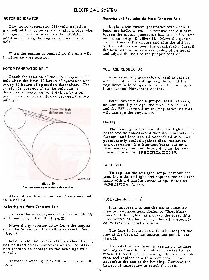
Check the tension of the motor -generatorbelt after the first 10 hours of operation andevery 50 hours of operation thereafter. Thetension is correct when the belt can bedeflected a maximum of 1/4-inch by a tenpound force applied midway between the twopulleys.
A satisfactory generator charging rate ismaintained by the voltage regulator. If theregulator fails to operate correctly, see yourInternational Harvester dealer.
Note: Never place a jumper lead between,or accidentally bridge, the "BAT'I terminaland the IIF'I terminal on the regulator, as thiswill damage the regulator.
LIGHTS
The headlights are sealed-beam lights. Theparts are so constructed that the filament, re-flector, and lens are all assembled in a unitpermanently sealed against dirt, moisture,and corrosion. If a filament burns out or alens breaks, the complete unit must be re-placed. Refer to "SPECIFICA TIONS't.
TAILLIGHT
To replace the taillight lamp, remove thelens from the taillight and replace the taillightlamp with a 4 candle power lamp. Refer to"SPECIFICATIONS".Illust.19
Correct motor-generotor belt tension.
FUSE (Electric Lighting)Also follow this procedure when a new belt
is installed.
Adjusting the Motor-Generator Belt It is important to use the same capacityfuse for replacement. Refer to "Specifica-tions ". If the lights fail, check the fuse. If afuse continually burns out, check the electri-cal wiring for short circuits.
Loosen the motor-generator brace bolt flAIland mounting bolts f'B", Illust. 20.
Move the generator away from the engineuntil the tension on the belt is correct. SeeIllust. 19.
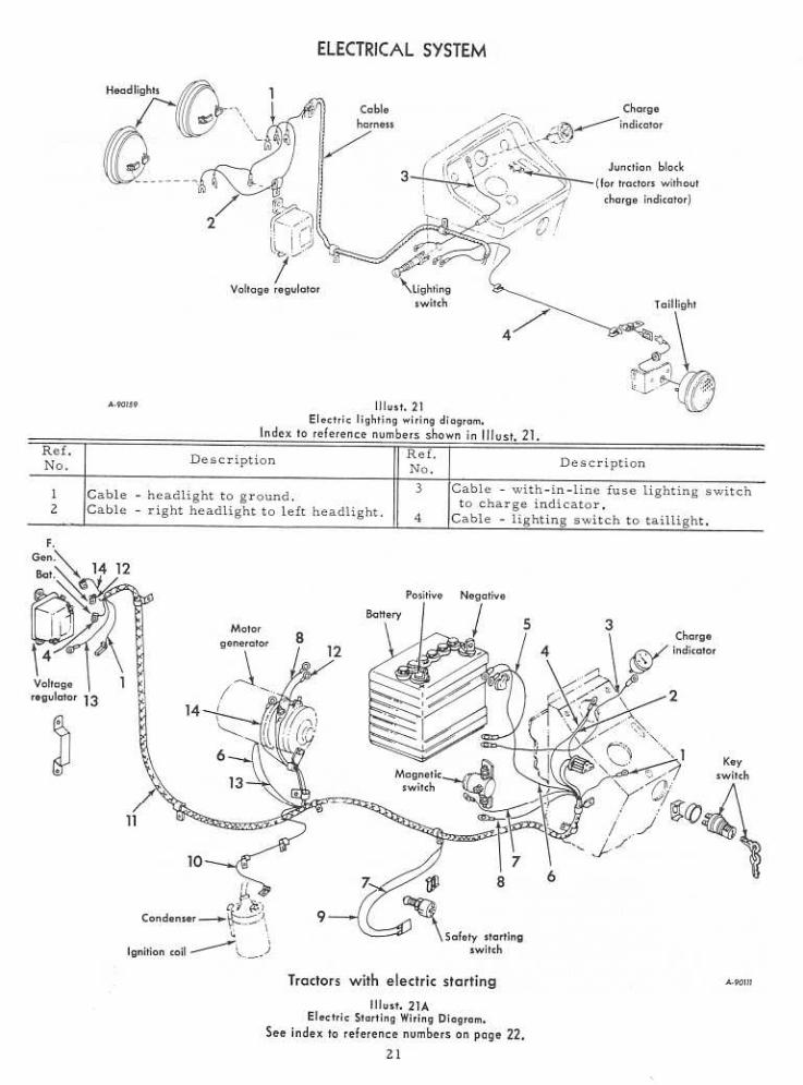
The fuse is located in a fuse housing in theline at the back of the instrument panel. SeeIllust.21.
Note: Under no circumstances should a prybar be used on the motor -generator to obtainbelt tension as damage to the bearings willire suIt.
To install a new fuse, press in on the fusehousing cap and turn counterclockwise to re-move it from the fuse housing. Remove the oldfuse and replace it with a new one. Then re-assemble the cap to the housing. Remove thebattery if necessary to reach the fuse.
Tighten mounting bolts "B" and brace bolt"A".
lq

ELECTRICAL SYSTEM
Jllust.20Electrical units an the right side af the tractor.
"lust. 20AElectrical units on the left side of the tractor.
20
ELECTRICAL SYSTEM
Index to reference numbers shown in Illust. 21A.
Ref.
No.Ref.No. DescriptionDescription
1
8
9
10
3
4 1112
5 13
6
Cable -lighting switch to headlampjunction -violet.
Cable -key switch "BAT" terminal tocharge indicator "NEa. II terminal -
light green.Cable assembly. Charge indicator to
magnetic switch.Cable -charge indicator lINEa. II ter-
minal to regulator "BA T" terminal-gray.
Cable -battery positive (+) terminal tomagnetic switch.
Cable -battery neg.ative (-) terminal tomotor generator ground -white.
Cable -safety starting switch to mag-netic switch -orange w/black tracer.
14
Cable -magnetic switch to generator 'IA'Iterminal -red.
Cable -safety starting switch to key ig-nition switch "ST" terminal -orange.
Cable -ignition coil positive (+) ter-minal to key ignition switch "IGN"terminal -black.Cable
harness.Cable -regulator "GEN" terminal to
generator "A" terminal -light blue.Cable -ground junction to voltage regu-
lator base ground -white with blacktracer.Cable
-generator "F" terminal to volt-age regulator "F" terminal -yellow.
7
STORAGE BATTERY Keeping the battery fully charged not onlyadds to its life but makes it available for instantuse
when needed.Battery and Cabl es
Before working on any part of the electri-cal system, disconnect the battery groundcable at the battery negative (-) terminal. SeeIllust.20. Do not reconnect this cable until allwork has been completed. This will preventshorting and damage to any of the electricalunits. Examine the electrical cables occasion-ally to be sure they are not being frayed bycontact with adjacent parts.
Liquid
Level
Check the battery at least once a month forwater level.
The electrolyte (acid and water) in eachcell should be at ring level at all times to pre-vent battery failure. When the electrolyte isbelow this level, add pure, distilled water.
When replacing a battery, make certain theground cable is connected to the negative (-)terminal on the battery. Be sure the rubberboot is properly positioned over the positive(+) terminal on the battery. Note: Both cablesmust be assembled with the nuts to the insideof the terminals to prevent shorting againstthe pedestal.
Acid or electrolyte should never be addedexcept by a skilled battery man. Under nocircumstances add any special battery 'Idopes, IIsolutions or powders.
Cleaning and Servicing the Battery
Caution! Electric storage batteries give offhighly inflammable hydrogen gas when charg-ing and continue to do so for some time afterreceiving a steady charge.
Caution! Do not under any circumstancesallow an electric spark or an open flame nearthe battery. Do not lay tools across batteryterminals as this may result in a spark orshort circuit which may cause an explosion.Be careful to avoid spilling any electrolyteon hands or clothing.
Occasionally remove the battery cables andbrighten the terminal contact surfaces withwire wool, and reassemble them. Apply alight coat of vaseline or chassis lubricant. Besure the terminals are clamped tightly andthat the battery is fastened securely in the bat-tery box. Replace unserviceable cable. Keepthe vent holes in the battery filler caps open.
For dependable battery service, see yourInternational Harvester dealer.
22
FRONT WHEEL TOE-IN
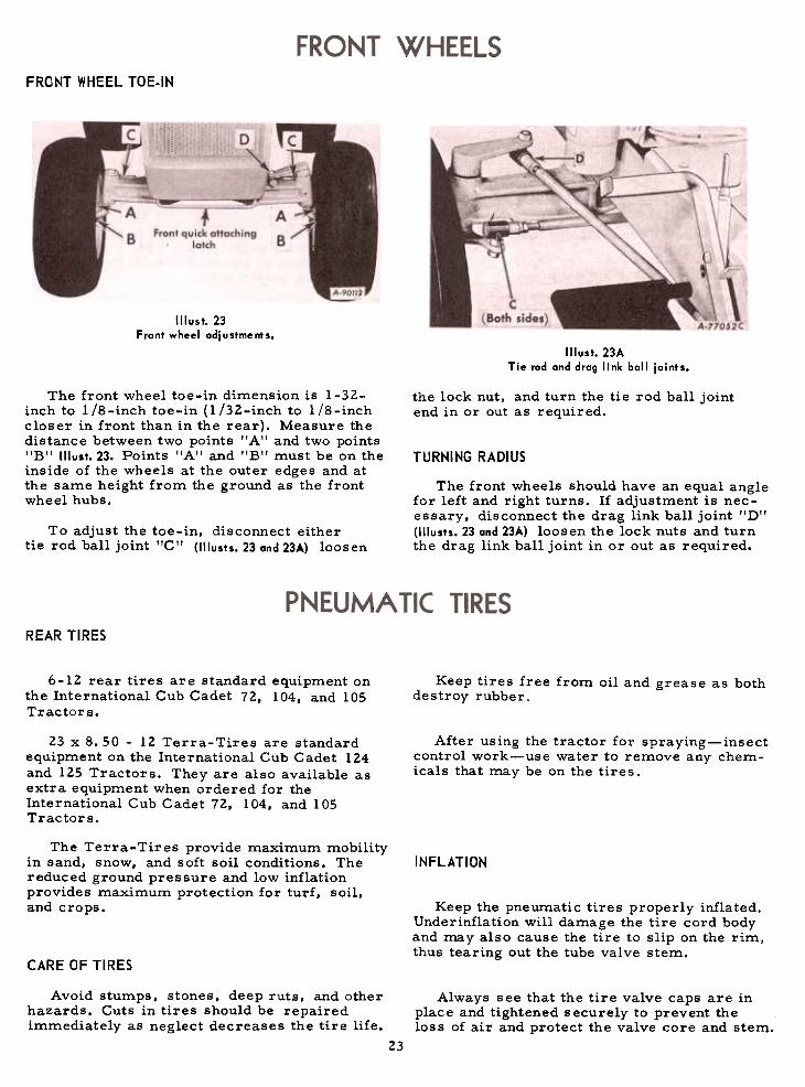
Illust. 23Front wheel odjustments.
Illust. 23ATie rod ond drog link ball joints.
The front wheel toe-in dimension is 1-32-inch to liS-inch toe-in (1/32-inch to liS-inchcloser in front than in the rear). Measure thedistance between two points "A'I and two points"B" Illust.23. Points "A'! and "B" must be on theinside of the wheels at the outer edges and atthe same height from the ground as the frontwheel hubs.
the lock nut, and turn the tie rod ball jointend in or out as required.
TURNING RADIUS
The front wheels should have an equal anglefor left and right turns. If adjustment is nec-essary, disconnect the drag link ball joint I'D'!(1IIusts. 23 and 23...) loosen the lock nuts and turnthe drag link ball joint in or out as required.
To adjust the toe-in, disconnect eithertie rod ball joint "C" (1IIusts. 23 and 23A) loosen
REAR TIRES
6-12 rear tires are standard equipment onthe International Cub Cadet 72, 104, and 105Tractors.
Keep tires free from oil and grease as bothdestroy rubber.
23 x 8.50 -12 Terra-Tires are standardequipment on the International Cub Cadet 124and 125 Tractors. They are also available asextra equipment when ordered for theInternational Cub Cadet 72, 104, and 105Tractors.
After using the tractor for spraying-insectcontrol work-use water to remove any chem-icals that may be on the tires.
The Terra-Tires provide maximum mobilityin sand, snow, and soft soil conditions. Thereduced ground pressure and low inflationprovides maximum protection for turf, soil,and crops.
INFLATION
Keep the pneumatic tires properly inflated.Underinflation will damage the tire cord bodyand may also cause the tire to slip on the rim,thus tearing out the tube valve stem.
CARE OF TIRES
Avoid stumps, stones, deep ruts, and otherhazards. Cuts in tires should be repairedimmediately as neglect decreases the tire life.
Always see that the tire valve caps are inplace and tightened securely to prevent theloss of air and protect the valve core and stem.
23
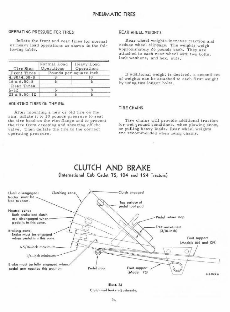

CLUTCH AND BRAKE
(International Cub Cadet 72, 104 and 124 Tractors)
As the clutch and brake are both operatedby the same pedal, care must be taken tomaintain a neutral zone so the clutch is dis-engaged when the brake is applied.
ADJUSTING THE CLUTCH
It is important that a clearance of .050-inch be maintained between the clutch releaselever and the clutch release bearing. In orderto maintain this clearance. the pedal shouldhave a free movement of approximately 3/16-inch. See Illust. 24. This measurement is takenat the point of contact of the pedal arm withthe front edge of the pedal return stop.
The clutch pedal adjustments are set at thefactory and should not require frequent atten-tion unless the linkage has been disturbed orwhen the pedal movement becomes less than3/ l6-inch. When it is necessary to adjust theclutch, turn the adjusting nut !'AII on the clutchrelease rod (1IIust. 25) in or out as required toget the proper measurements.
ADJUSTING THE BRAKE
The brake should engage when the pedalarm is pressed down to within a maximum ofl-5/l6-inches and a minimum of 3/4-inch dis-tance above the top of the left foot support,which serves as the pedal stop. See IIIust. 24.
It may be possible to push the pedal all theway down to the pedal stop, but this is of noconcern as long as the brake is engaged whenthe pedal a-rm is at least 3/4-inch above ttlepedal
stop.
To adjust the brake, loosen the jam nut"B" and turn the brake lever adjusting screwlICIt (1IIust. 25) in or out as required to get thismeasurement. The brake must not engagebefore the pedal arm is within the maximumdistance of 1-5/16-inches above the pedal stop.
Illust. 25
Clutch and brake adjustments.
25
BRAKE(International Cub Cadet 105 and 125 Tractors)
=,
A-86719 A
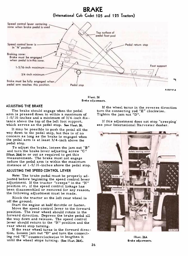
Illust.26Brake adjustments.
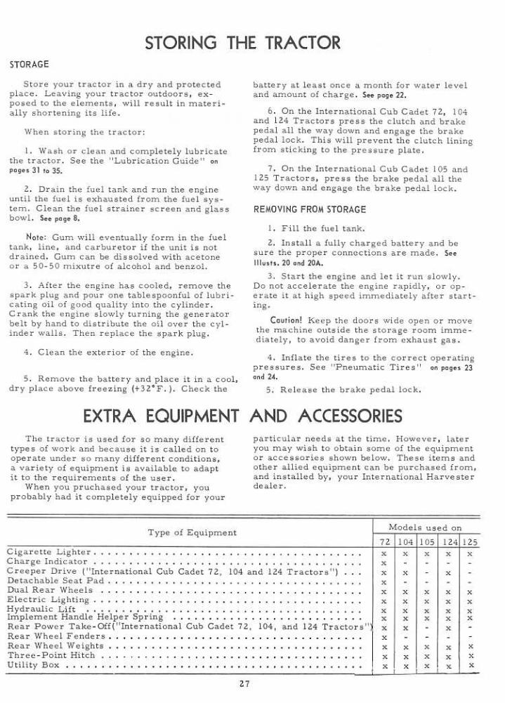
If the wheel turns in the reverse directionturn the connecting rod l'Elf clockwise.Tighten the jam nut I'DI'.
If this adjustment does not stop "creepingsee your International Harvester dealer.
ADJUSTING THE BRAKEThe brake should engage when the pedal
arm is pressed down to within a maximum of1-5/16-inches and a minimum of 3/4-inch dis-tance above the top of the left foot support,which serves as the pedal stop. See Illust. 26.
It may be possible to push the pedal all theway down to the pedal stop, but this is of noconcern as long as the brake is engaged whenthe pedal arm is at least 3/4 -inch above the
pedal stop.To adjust the brake. loosen the jam nut "B"
and turn the brake lever adjusting screw "c"(1IIust. 26A) in or out as required to get thismeasurement. The brake must not engagebefore the pedal arm is within the maximumdistance of 1-5/16-inches above the pedal stop.
ADJUSTING THE SPEED CONTROL LEVERNote: The brake pedal must be properly ad-
justed before beginning the speed control leveradjustment. If the tractor "creeps" in the "N"position or, if the speed control linkage hasbeen disassembled or removed for any reason,the following adjustment must be made.
Block the tractor so the left rear wheel isoff the ground.
Start the engine at half throttle or faster.Move the speed control lever to the forward
position. The rear wheel should rotate in theforward direction. Depress the brake pedal allthe way down and release. The speed controllever should return to the "N" position and therear wheel stop turning.
1£ the rear wheel turns in the forward direc-tion, loosen jam nut "D" and turn the connect-ing rod I'E" counterclockwise to lengthen ituntil the wheel stops turning. (See Illust. 26A).
Illust. 26ABrake adjustments.
26
TROUBLE SHOOTING
Possible RemedyPossible Cause
LACK OF POWER -Continued
Incorrect timing or faulty ignition. Clutch slipping (Models 72, 104 and 124)
Brake drags.
See "Breaker Points and Spark Plug" on pages18 and 19.
Adjust the free travel of the pedal; see pages 24and 25.
Adjust the brake; see pages 24 and 25.
ENGINE OVERHEATS
Insufficient cool air, dirty air intake screen, Keep the air intake area and cooling fins clean;shroud, or cooling fins. See "Engine Cooling and Air Cleaner"
on poge 17.
CREEPING
Speed control lever out of adjustment (Models 105 and 125) See !'Speed Cont,rol Lever Adjustment!'on poge 26.
':' See your International Harvester dealer.
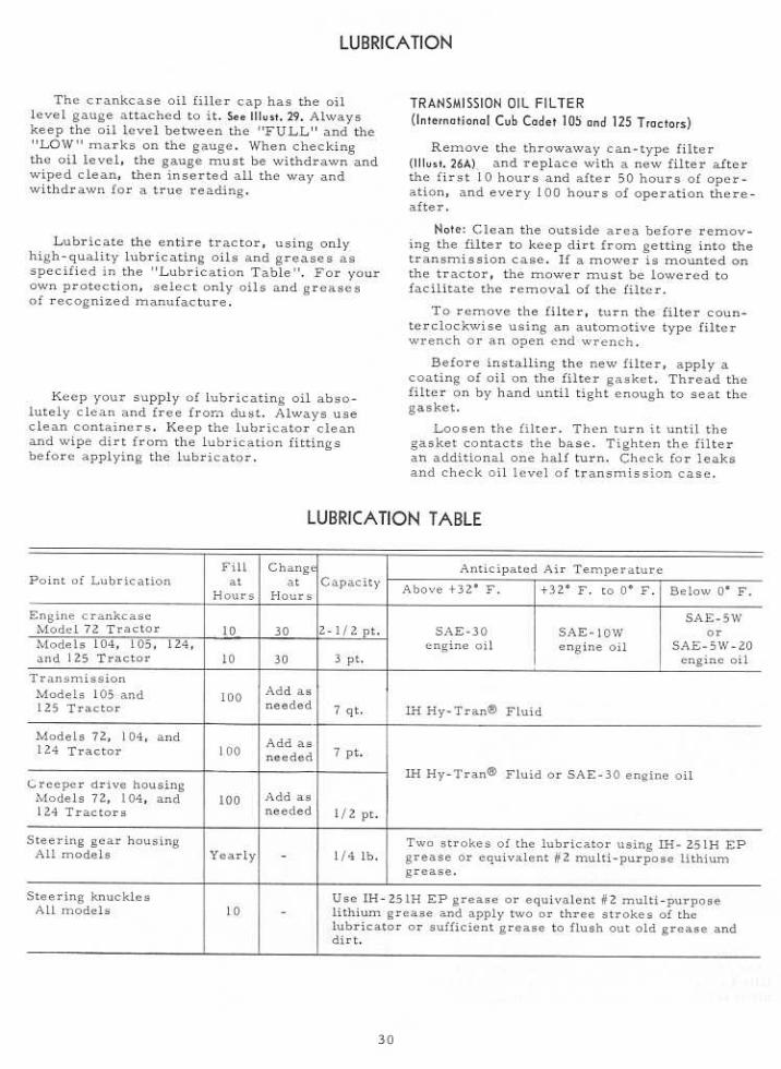
ENGINE OIL
The tractor is shipped from the factorywith shipaway engine oil in the crankcase. Ifthe engine is to be operated at temperaturesbetween +75 degrees F and 0 degrees F, thisoil can be used for the first five hours ofoperation. If the temperatures are not withinthis range, drain the oil from the crankcaseand replace it with new oil as specified in theII Lubrication T able", The engine oil must be
drained and replaced with new oil every 30hours of engine operation thereafter.
Oils designated "For Service MS" arerecommended for this engine.
To aid starting. the selection of crankcaselubricating oils should be based on the lowestanticipated temperature until the next drainperiod.
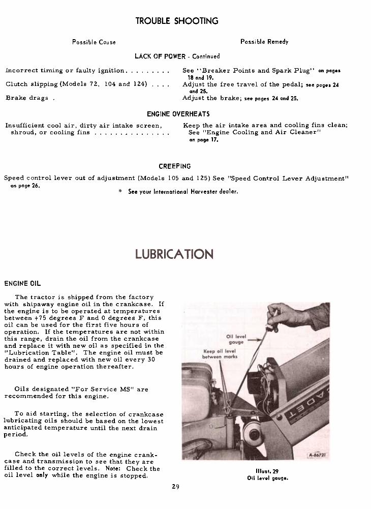
Check the oil levels of the engine crank-case and transmission to see that they arefilled to the correct levels. Note: Check theoil level only while the engine is stopped. Illust.29
Oil level gauge.
29

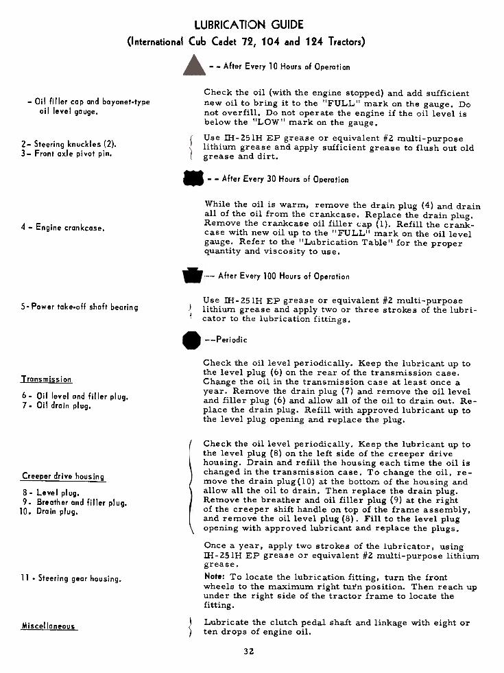
LUBRICATION GUIDE
(International Cub Cadet 72, 104 and 124 Tractors)
--After Every 10 Hours of Operation
-Oil filler cap and bayonet-typeoil level gauge.
Check the oil (with the engine stopped) and add sufficientnew oil to bring it to the "FULL" mark on the gauge. Donot overfill. Do not operate the engine if the oil level isbelow the "LOW" mark on the gauge.
Use IH-25lH EP grease or equivalent #2 multi-purposelithium grease and apply sufficient grease to flush out oldgrease
and dirt.
2- Steering knuckles (2).3- Front oxle pivot pin.
--After Every 30 Hours of Operation
While the oil is warm, remove the drain plug (4) and drainall of the oil from the crankcase. Replace the drain plug.Remove
the crankcase oil filler (;ap (1). Refill the crank-case with new oil up to the "FULL" mark on the oil levelgauge.
Refer to the "Lubrication Table" for the properquantity and viscosity to use.
4 -Engine crankcase.
--After Every 100 Hours of Operation
Use IH -25lH EP grease or equivalent #2 multi-purposelithium grease and apply two or three strokes of the lubri-cator to the lubrication fittings.
S-Power
take-off shaft bearing
--Periodic
Check the oil level periodically. Keep the lubricant up tothe level plug (6) on the rear of the transmission case.Change the oil in the transmission case at least once ayear. Remove the drain plug (7) and remove the oil leveland filler plug (6) and allow all of the oil to drain out. Re-place the drain plug. Refill with approved lubricant up tothe level plug opening and replace the plug.
Transmission
6. Oil level and filler plug.7. Oil drain plug.
Creeper drive housing
8. Level plug.9. Breather and filler plug.
10. Drain plug.
\
11 .Steering gear hausing.
Check the oil level periodically. Keep the lubricant up tothe level plug (8) on the left side of the creeper drivehousing. Drain and refill the housing each time the oil ischanged in the transmission case. To change the oil, re-move the drain plug (10) at the bottom of the housing andallow all the oil to drain. Then replace the drain plug.Remove the breather and oil filler plug (9) at the rightof the creeper shift handle on top of the frame assembly,and remove the oil level plug (8). Fill to the level plugopening with approved lubricant and replace the plugs.
Once a year, apply two strokes of the lubricator, usingill-251H EP grease or equivalent #2 multi-purpose lithiumgrease.Note: To locate the lubrication fitting, turn the frontwheels to the maximum right turn position. Then reach upunder the right side of the tractor frame to locate thefitting.
Lubricate the clutch pedal shaft and linkage with eight orten drops of engine oil.Miscellaneou§
31.
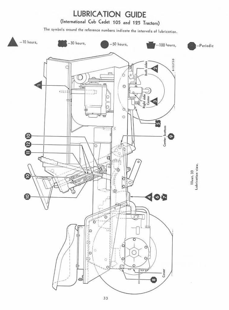

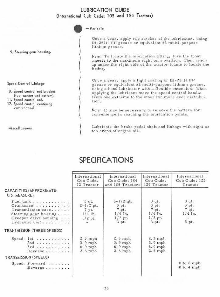
LUBRICATION GUIDE(International Cub Cadet 105 and 125 Tractors)
--After Every 10 Hours of Operation
1. Oil filler cap and bayonet-typeail level gauge.
Check the oil (with the engine stopped) and add sufficientnew oil to bring it to the "FULL" mark on the gauge. Donot overfill. Do not operate the engine if the oil level isbelow the "LOW" mark on the gauge.
Use IH-25lH EP grease or equivalent #2 multi-purposelithium grease and apply sufficient grease to flush out oldgrease and dirt.
2. Steering knuckles (2).3. Front axle pivot pin.
Note: After the first 10 hours only, remove the old filterand replace with a new filter as instructed on page 30.Change the oil filter after 50 hours and every 100 hoursof operation thereafter.
4. Transmission ail filter,
--After Every 30 Hours of Operation
While the oil is warm, remove the drain plug (5) anddrain all of the oil from the crankcase. Replace the drainplug. Remove the crankcase oil filler cap (I). Refill thecrankcase with new oil up to the "FULL" mark on the oillevel gauge. Refer to the "Lubrication Table" for theproper quantity and viscosity to use.
S. Engine crankcase.
--After Every 50 Hours of Operotion
Note: After the first 50 hours only, remove the old filterand replace with a new filter as instructed on poge 30.Change the oil filter every 100 hours of operationthereafter.
6. Transmission oil filter.
.--After Every 100 Hours of Operation
7. Transmission oil filter. Change the oil filter and replace with a new filter asinstructed on poge 30.
--Periodi c
Transmission Check the oil level periodically. Keep the lubricant up tothe level plug (8) on the rear of the transmission casecover.
8.
Oil level and filler plug.
34

MEMORANDA
39

MEMORANDA
40

MEMBER, NATIONAL SAFETY COUNCIL
Accidents
be
No accident-prevention program can be suc-
cessful without the wholehearted co-operation
of the person who is directly responsible for the
operation of equipment.
To read accident reports from allover the
country is to be convinced that a large number
of accidents can be prevented only by the
operator anticipating the result before the
accident is caused and doing something about
it. No power-driven equipment, whether it be
transportation or processing, whether it be on
the highway, in the harvest field or in the
industrial plant, can be safer than the man who
is at the controls. If accidents are to be pre-
vented-and they can be prevented-it will be
done by the operators who accept a full measure
of their responsibility.
It is true that the designer, the manufacturer,
the safety engineer can help; and they will help,
but their combined efforts can be wiped out by
a single careless act of the operator.It is said that r 'the best kind of a safety
device is a careful operator. II We ask you
to be that kind of an operator.
Price $1.00
