opportunities for organic rankine cycles in the process industries
TRANSCRIPT

Opportunities for Organic
Rankine cycles (ORCs) in
the Process Industries
T.P. Handayani
A.P. Harvey
D.A. Reay
R. Law
Sustainable Thermal Energy Management in the Process Industries International Conference
(SusTEM2011)
25-26 October 2011, Newcastle upon Tyne, United Kingdom

Author background
1st year MPhil Student at School of Chemical
Engineering and Advanced Materials, Newcastle
University
Working on EPSRC funded OPTITHERM project:
OPTImising THermal Energy Recovery, utilisation and
Management
Overall aim to produce an Organic Rankine cycle
(ORC) Expert System software package

Presentation Outline
1. Introduction
2. Working fluids in ORCs
3. Configurations of ORC machines
4. ORC Manufacturer
5. Proposed decision tree
6. Conclusions

Presentation Outline
1. Introduction
2. Working fluids in ORCs
3. Configurations and applications of
ORC machines
4. ORC Manufacturer
5. Proposed decision tree
6. Conclusions

Introduction : Low grade waste heat
Low grade heat (> 100oC) released to
environment create thermal pollution
Steam Rankine cycle economical to
recover high grade waste heat (> 350oC)

Introduction : What is an ORC ?
Moran, M.J. et al,
What is an ORC ?
Similiar to steam cycle but utilizes
an Organic fluid instead of water
Mario Gaia, 2011
Mario Gaia, 2011

Introduction : How does it work ?
Pump
Condenser
Turbine
Evaporator
Saturated Liquid
Saturated Vapour Saturated Vapour
W power
Saturated Liquid
Work
Waste heat
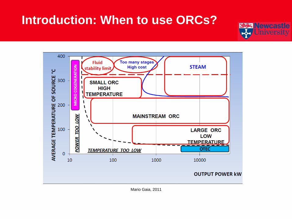
Introduction: When to use ORCs?
Mario Gaia, 2011

Introduction: When to use ORCs ?
Low grade waste
heat < 350oC
Direct
use
possibility
?
Heat
exchanger
recovery
possibility
?
Refrigeran
t required
on site ?
40-60 K
lift useful
?
Electrical
demand ?
Waste
heat
temperatu
re >100 C
Export heat ?
Pipe and duct
work?
Heat exchanger
network Absorption “chiller” Heat pump ORC
Yes Yes
Yes Yes
Yes
Yes
No No No
No
No
Objective : To show when to use an ORC in the process
industry
Presentation Outline
1. Introduction
2. Working fluids in ORCs
3. Configurations and applications of
ORC machines
4. ORC Manufacturer
5. Proposed decision tree
6. Conclusions

Introduction: Working fluids in ORCs
Chen et al Recommended
in ORCs
Why?
-Reduce droplets in outlet
turbine
- No superheat needed
-Low critical temperature
compared to water
Key rule to select the
working fluid:
Choose the temperature
closest to the waste heat
source
Chen et al, 2010

Presentation Outline
1. Introduction
2. Working fluids in ORCs
3. Configurations and applications of
ORC machines
4. ORC Manufacturer
5. Proposed decision tree
6. Conclusions

Configurations of ORCs
1. Conventional ORC
2. Dual Source ORC
3. Regenerative ORC
4. Recuperative ORC

Configuration of ORC
1. Conventional ORC
2. Dual Source ORC
3. Regenerative ORC
4. Recuperative ORC
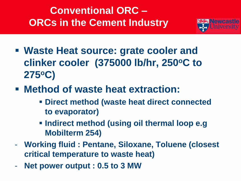
Conventional ORC –
ORCs in the Cement Industry
Waste Heat source: grate cooler and
clinker cooler (375000 lb/hr, 250oC to
275oC)
Method of waste heat extraction:
Direct method (waste heat direct connected
to evaporator)
Indirect method (using oil thermal loop e.g
Mobilterm 254)
- Working fluid : Pentane, Siloxane, Toluene (closest
critical temperature to waste heat)
- Net power output : 0.5 to 3 MW

Conventional ORC –
ORCs in the Cement Industry - 2
Heidelberger Zement ORC (Legmann, 2002)
Conventional ORC
Conventional
ORC Indirect
method

Conventional ORC –
ORCs in the Refinery Industry
Process Waste Heat
source
Source
temperature
(oC)
Average ORCs
system size (kW)
Atmospheric Distillation L, C 150 1794
Vacuum Distillation L, C 150 1947
Fluid Catalytic Cracking L, C 150 732
Hydrocracking L, C 146 1685
Hydrogen Plant G 150 3559
Catalytic Reforming L, C 137 4700
Hydrotreating L, C 121 1031
Hydrofening L, C 121 1087
Waste heat source in “West Coast” oil refinery
(Drake, 1985)
Working fluids : R113
L = liquid; C = condensable vapor, G = Gas Potential for ORC
Possible Heat source

Conventional ORC –
ORC in the Refinery Industry
Rose, R. K, 1979
Conventional
ORC
Working fluid: Fluorocarbon (banned now)
Bypass valve to take full
evaporator load if there is problem
in turbine

Conventional ORC –
ORC in the Refinery Industry
Working fluid: R113
Drake, R. 1985
Parallel utilization of ORC
(each ORC provide 750 –
1500 kW)
First
ORC
Second
ORC

Conventional ORC –
ORC in the Refinery Industry
Working fluid: R113
Drake, R. 1985
Parallel utilization of ORC
(each ORC provide 750 –
1500 kW)
Configurations of ORCs
1. Conventional ORC
2. Dual Source ORC
3. Regenerative ORC
4. Recuperative ORC
Dual source ORC –
in the Cement Industry
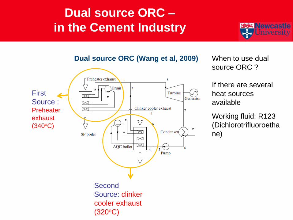
Dual source ORC (Wang et al, 2009)
First
Source : Preheater
exhaust
(340oC)
Second
Source: clinker
cooler exhaust
(320oC)
Working fluid: R123
(Dichlorotrifluoroetha
ne)
When to use dual
source ORC ?
If there are several
heat sources
available

Dual source ORC –
in the Cement Industry
Dual source ORC (Wang et al, 2009)
Dual source ORC –
ORCs in the Food Industry
Waste heat :
- Foul gas from the fryer (120oC)
- Effluent gas stream from the heat
exchanger to the stack (140oC)
Working fluid : R245fa
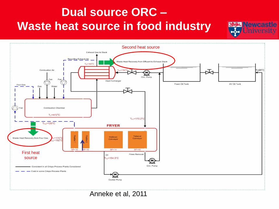
Dual source ORC –
Waste heat source in food industry
Anneke et al, 2011
First heat
source
Second heat source
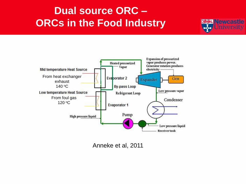
Dual source ORC –
ORCs in the Food Industry
From foul gas
120 oC
From heat exchanger
exhaust
140 oC
Anneke et al, 2011

Configurations of ORCs
1. Conventional ORC
2. Dual Source ORC
3. Regenerative ORC
4. Recuperative ORC

What is Regenerative ORC ?
Regenerative ORC is one that uses a
feed water heater to recover the outlet
turbine vapour
Objective (Mago et al, 2008):
To increase the thermal efficiency
To decrease the irreversibility
To increase the second law efficiency

Comparison Conventional ORC and
Regenerative ORC
Moran, M.J. et Pump
Condenser
Turbine
Evaporator
Pump
Condenser
HP Turbine
Evaporator
Feed water
heater
Pump Moran et al, 2008
Conventional ORC Regenerative ORC
Lp Turbine
The waste heat: furnace flue gas waste heat (398oC – 454oC)
Working fluid : Toluene (critical temperature 320oC)

Configurations of ORCs
1. Conventional ORC
2. Dual Source ORC
3. Regenerative ORC
4. Recuperative ORC

What is recuperative ORC?
Recuperative ORC is one that uses a
recuperator employing the turbine outlet
vapor to heat up the working fluid going
to the boiler (Hjartarson, 2009)
Why use a recuperator:
To reduce the heat load in the evaporator
To increase the thermal efficiency

Recuperative ORC –
ORCs in chemical industry
Waste heat: Furnace (220OC – 400oC)
Tested three types of ORC
in Elkem ferrosilicon plant.
Configuration with one
recuperator produced
maximum power compared
to basic and two
recuperator types
(Hjartarson, 2009)

ORC configuration - Summary
ORC
type
Conventional Dual Source Regenerative Recuperative
What ?
Why ?
When ?
Where ?
1 heat source
Pump,
Evaporator,
Condensor,
Turbine
Generator
2 heat source,
Pump,
Evaporator,
Condensor,
Turbine
Generator
1 heat source,
Pump, Evaporator,
Condensor,
Turbine,
Feed water heater
Generator
1 heat source,
Pump, Evaporator,
Condensor,
Turbine,
Recuperator
Generator
To convert
waste heat to
electrical power
To produce more
power, To increase
thermal efficiency,
to reduce
irreversibility
To produce more
power, To increase
thermal efficiency,
to reduce
irreversibility
To produce more
power, To increase
thermal efficiency,
to reduce
irreversibility
Waste heat
>100 C
electrical power
2 Waste heat
source >100 C
If thermal
efficiency low
If thermal
efficiency low
Most industrial
plant (Cement,
Refinery)
Cement, food
industry
Glass industry
Chemical

Presentation Outline
1. Introduction
2. Working fluids in ORCs
3. Configurations and applications of
ORC machines
4. ORC Manufacturer
5. Proposed decision tree
6. Conclusions
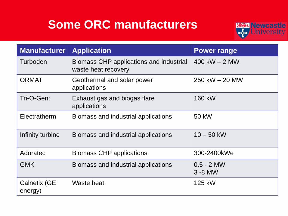
Some ORC manufacturers
Manufacturer Application Power range
Turboden Biomass CHP applications and industrial
waste heat recovery
400 kW – 2 MW
ORMAT Geothermal and solar power
applications
250 kW – 20 MW
Tri-O-Gen: Exhaust gas and biogas flare
applications
160 kW
Electratherm Biomass and industrial applications
50 kW
Infinity turbine Biomass and industrial applications
10 – 50 kW
Adoratec Biomass CHP applications 300-2400kWe
GMK Biomass and industrial applications 0.5 - 2 MW
3 -8 MW
Calnetix (GE
energy)
Waste heat 125 kW
Presentation Outline
1. Introduction
2. Working fluids in ORCs
3. Configurations and applications of
ORC machines
4. ORC Manufacturer
5. Proposed decision tree
6. Conclusions

Proposed decision tree
Waste Heat
Temperature
Working fluid temperature
near to waste heat
temperature? Increase the evaporator pressure
and decrease the condenser
pressure
Check the quality of vapour
in outlet turbine
If the quality of
vapour in turbine
outlet < 90%
Superheat ed
the vapor in
turbine inlet
using steam
generator
Improve the quality of
vapor in turbine outlet
Reheat the vapor
from first turbine
before enter the
second turbine
Regenerative
open feed water
heater
Dual
Source
ORC
Recuperative
ORC
Increase the
efficiency ?
Two heat
source ?
Stop
No
No
No
Yes
No
Yes
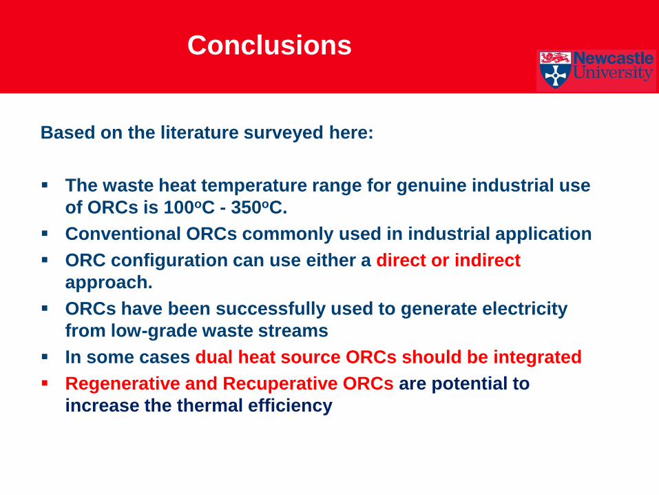
Conclusions
Based on the literature surveyed here:
The waste heat temperature range for genuine industrial use
of ORCs is 100oC - 350oC.
Conventional ORCs commonly used in industrial application
ORC configuration can use either a direct or indirect
approach.
ORCs have been successfully used to generate electricity
from low-grade waste streams
In some cases dual heat source ORCs should be integrated
Regenerative and Recuperative ORCs are potential to
increase the thermal efficiency

Acknowledgement
EPSRC project entitled OPTITHERM:
OPTImising THermal Energy, Recovery,
utilisation and Management in the
process industries (project no.
EP/G061467/1)
Partner universities
Other industrial partners

Thank you for your attention