optex vxi series datasheet - store & retrieve data anywhere
TRANSCRIPT

SPECIFICATIONS
Detection methodPIR coverage
PIR distance limitDetectable speed
SensitivityPower inputCurrent drawAlarm period
Warm-up periodAlarm output
Trouble outputTamper output
LED indicator
RF interferenceOperating temperatureEnvironment humidity
International protectionMounting
Mounting heightWeight
Accessories
* Specifications and design are subject to change without prior notice.
Model VXI-R VXI-RAM VXI-RDAM
12.0 m (40 ft) wide / 16 zones12 - 2.5 m (5 levels)
0.3 – 1.5 m/s (1 - 5 ft/s)2.0°C (3.6°F) at 0.6 m/s (2 ft/s)
3 – 9 V DC(Lithium or Alkaline Battery)10μA (standby) / 4 mA (max)
at 3 V DC2.0 ±1 sec.
Approx. 60 sec. (LED blinks)N.C. / N.O. Selectable-Solid State Switch 10 V DC 0.01 A (max)N.C. / N.O. Selectable-Solid State Switch 10 V DC 0.01 A (max)
No alarm 10 V/m
95% max.IP55
Wall, Pole (Outdoor, Indoor)0.8 – 1.2 m (2.64 ft – 3'94 ft)
Connector for POWER and ALARM, Connector for TROUBLE, Screw (4×20mm) ×2, Masking seal ×3
Detection methodPIR coverage
PIR distance limitDetectable speed
SensitivityPower input
Current draw
Alarm periodWarm-up period
Alarm outputTrouble output
LED indicator
RF interferenceOperating temperatureEnvironment humidity
International protectionMounting
Mounting heightWeight
Accessories
Passive infrared
Disable: During normal operation.Enable: During WALK TEST or LED SW on.
Red: Warm-up, alarm, masking detection (VXI-RAM only)
-20 – +60°C (-4 – +140°F)
500 g (17.7 oz.)
9μA (standby) / 4 mA (max) at 3 V DC
Passive infrared & Microwave
18μA (standby) / 8 mA (max)at 3 V DC
Disable: During normal operation.Enable: During WALK TEST or LED SW on.Red: Warm-up, alarm, masking detection.Yellow: Warm-up, MW detect.
-20 – +45°C (-4 – +113°F)
600 g (21.2 oz.)
12.0 m (40 ft) 90° wide / 16 zones12 - 2.5 m (5 levels)
0.3 – 1.5 m/s (1 - 5 ft/s)2.0°C (3.6°F) at 0.6 m/s (2 ft/s)
9.5 – 18 V DC24 mA (max) at 12 V DC
2.0 ±1 sec.Approx. 60 sec. (LED blinks)
N.C. / N.O. Selectable 28 V DC 0.1 A (max)
N.C. 28 V DC 0.1 A (max) open when cover removed.
No alarm 10 V/m
95% max.IP55
Wall, Pole (Outdoor, Indoor)0.8 – 1.2 m (2.64 ft – 3'94 ft)
Screw (4×20 mm) ×2 , Wiring sponge ×3 , Masking seal ×3
Passive infrared
Red: Warm-up, alarm,masking detection (VXI-AM only)
-30 – +60°C (-22 – +140°F)
500 g (17.7 oz.)
N.C. 28 V DC 0.1 A (max)
20 mA (max) at 12 V DC
-
Model VXI-ST VXI-AM VXI-DAM
Unit:mm(inch)
The actual detectiondistance is dependenton the thermal conditionswithin the given environment.
SIDE VIEW (Detection Distance by Positions)
Position 1 : Approx. 12m/40ft (Default)
0 5m 10m 12m
1m
Position 2 : Approx. 8.5m/27.9ft
0 5m 10m 12m
1m
Position 3 : Approx. 6.0m/19.7ft
0 5m 10m 12m
1m
Position 4 : Approx. 3.5m/11.5ft
0 5m 10m 12m
1m
Position 5 : Approx. 2.5m/8.2ft
0 5m 10m 12m
1m
TOP VIEW(Area diagram for D position)
12m
10m
5m
12m 12m10m 10m5m 5m00a
b
c
d
ef
g hi
j
k
l
m
n
b
d k
m
MW
PIRDA B C E F G
185.9(7.32)
105.5(4.15 ) Pitch=83.5(3.29)
DETECTION AREA DIMENSIONS
TEL:Tech:URL:
+1-909-993-5770(800) 966-7839http://www.optexamerica.com/
OPTEX INCORPORATED (USA)
TEL:URL:
+55-11-2225-0934http://www.optexdobrasil.com.br/
OPTEX DO BRASIL LTDA.
TEL:URL:
+91-124-4035704http://www.optex.net/in/
OPTEX PINNACLE INDIA PRIVATE LIMITED
TEL:URL:
+82-2-719-5971http://www.optexkorea.com/
OPTEX KOREA CO., LTD. (KOREA)
OPTEX (DONGGUAN) CO., LTD. SHANGHAI OFFICE (CHINA)TEL:URL:
+86-21-34600673http://www.optexchina.com/
TEL :URL:
+44-1628-631000http://www.optex-europe.com/
OPTEX (EUROPE) LTD. (UK)
TEL:URL:
+33-437-55-50-50http://www.optex-security.com/
OPTEX SECURITY SAS (FRANCE)
TEL:URL:
+48-22-598-06-55http://www.optex.com.pl/
OPTEX SECURITY Sp.z o.o. (POLAND)
5-8-12 Ogoto Otsu Shiga 520-0101 JAPANTEL:URL:
+81-77-579-8670http://www.optex.co.jp/e/
OPTEX CO., LTD. (JAPAN)
No. 77040-00-15747-1306
Passive infrared & Microwave
35 mA (max) at 12 V DC
Red: Warm-up, alarm,masking detection.
Yellow: Warm-up, MW detect.
-20 – +45°C (-4 – +113°F)
600 g (21.2 oz.)
VXI-T-Bracket BATTERY BOX (RBB-01)
*Battery not included.
Wall Tamper (WRS-04)for R, RAM, RDAM models
Different values of EOL resistances can be instantly set by plugging in optional modules. Please refer to the relevant control panels manual to confirm matching resistance values.
Plug in EOL(End of line) Resistor Modules
CR123A x 3(3.0VDC)CR2 x 3(3.0VDC)1/2AA x 3(3.6VDC)1/2AA x 6(7.2VDC x 3)*
*3.6 VDC 1/2 AA battery in series.
Alarm: 2.2kΩ / Tamper: 4.7kΩ / Trouble: 2.2kΩPEU-A(PACK)
Alarm: 4.7kΩ / Tamper: 4.7kΩ / Trouble: 6.8kΩPEU-B(PACK)
Alarm: 1.0kΩ / Tamper: 1.0kΩ / Trouble: 12kΩPEU-C(PACK)
Alarm: 1.0kΩ / Tamper: 1.0kΩ / Trouble: 3.0kΩPEU-D(PACK)
Alarm: 1.1kΩ / Tamper: 1.1kΩ / Trouble: 15kΩPEU-E(PACK)
Alarm: 5.6kΩ / Tamper: 5.6kΩ / Trouble: 5.6kΩPEU-F(PACK)
series
VXI-ST
VXI-AM
VXI-DAM
WIRED MODEL
: 12m wide 2PIRs standard
: Anti-masking
: 2PIRs with Microwave
BATTERY OPERATED MODEL
VXI-R
VXI-RAM
VXI-RDAM
: Battery operated 12m 2PIRs
: Battery operated Anti-masking
: Battery operated 2PIRs with Microwave
*VXI-DAM and VXI-RDAM can not be used due tomicrowave interference.
OPTIONS
Without a back box (VXI-ST / AM / DAM)
181.9(7.16)
64.5(2.54)
With a back box (VXI-R / RAM / RDAM)
70.9(2.80)
71.3(2.81)
for wired models
for ST, AM, DAM modelsWall Tamper (WRS-02)
*Not applicable for a use of a set of dual technology models (DAM & RDAM).
− Flexible Detection Patterns− Expanded Features in a Down-sized Body− Digitally Enhanced Reliability
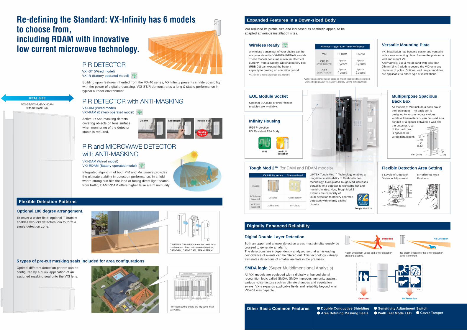
Flexible Detection Patterns
PIR DETECTOR
Optional 180 degree arrangement.
To cover a wider field, optional T-Bracket enables two VXI detectors join to form a single detection zone.
PIR DETECTOR with ANTI-MASKING
Active IR Anti-masking detects covering objects on lens surface when monitoring of the detector status is required.
PIR and MICROWAVE DETECTORwith ANTI-MASKING
Integrated algorithm of both PIR and Microwave provides the ultimate stability in detection performance. In a field where strong sun hits the land or facing direct light beams from traffic, DAM/RDAM offers higher false alarm immunity.
5 types of pre-cut masking seals included for area configurations
Optimal different detection pattern can be configured by a quick application of an assigned masking seal onto the VXI lens.
VXI-DAM (Wired model)VXI-RDAM (Battery operated model)
VXI-AM (Wired model)VXI-RAM (Battery operated model)
Other Basic Common Features ● Double Conductive Shielding● Area Defining Masking Seals
VXI reduced its profile size and increased its aesthetic appeal to be adapted at various installation sites.
Digital Double Layer Detection
Both an upper and a lower detection areas must simultaneously be crossed to generate an alarm. The detections are independently analyzed so that a misleading coincidence of events can be filtered out. This technology virtually eliminates detections of smaller animals in the premises.
Digitally Enhanced Reliability
Expanded Features in a Down-sized Body
Wireless Ready
Flexible Detection Area SettingTough Mod 2TM (for DAM and RDAM models)
No DetectionDetection
etc.
No Detection
All VXI models are equipped with a digitally enhanced signal recognition logic called SMDA. SMDA improves immunity against various noise factors such as climate changes and vegetation sways. VXIs expands applicable fields and reliability beyond what VX-402 was capable.
SMDA logic (Super Multidimensional Analysis)
No alarm when only the lower detectionarea is blocked.
VXI-ST (Wired model)VXI-R (Battery operated model)
mm (inch)
8 Horizontal AreaPositions
5 Levels of DetectionDistance Adjustment
OPTEX Tough Mod TM Technology enables a long-time sustainability of Dual-detection technology. Gold-plated Tough Mod increases durability of a detector to withstand hot and humid climates. Now, Tough Mod 2 extends the capability of Dual-detection to battery operated detectors with energy saving circuits.
VXI installation has become easier and versatile with a new mounting plate. Secure the plate on a wall and mount VXI.Alternatively, use a metal band with less than 25mm (1inch) width to secure the VXI onto any diameter of poles. Optional wall tamper modules are applicable to either type of installations.
Versatile Mounting Plate
Images
PCB boardMaterial Ceramic
Gold-platedAntennaMaterial
VX Infinity series Comventional
Wireless Trigger Life Time* Reference
VXI
CR123(3VDC 1300mAh) 6years 4years
4years 2yearsCR2
(3VDC 750mAh)
R, RAM
Approx
RDAM
Approx
Approx Approx
A wireless transmitter of your choice can be accommodated in VXI-R/RAM/RDAM models. These models consume minimum electrical current* from a battery. Optional battery box (RBB-01) can expand the battery capacity to prolong an operation period.
Optional EOL(End of line) resistor modules are available.
IP55 ProtectionUV Resistant ASA Body
*WTLT is an approximation based on hypothetical condition operated with settings; LED(OFF), AM(ON), Battery Saving Timer(120sec)
*As low as 9 micro amperage at a standby.
Infinity Housing
Anti UVProtection
IP55
All models of VXI include a back box in their packages. The back box is designed to accommodate various wireless transmitters or can be used as a conduit or a spacer between a wall and the detector. Use of the back box is optional for wired installations.
Multipurpose SpaciousBack Box
Tough Mod.2TM
Tough MicroWave Unit
2
EOL Module Socket
Use for masking optional area. Use for two wing area setting.(A or G position)
1 2
a jihgfedcb nmlka jihgfedcb nmlk
Use for masking optional area. Use for two wing area setting.(A or G position)
1 2
a jihgfedcb nmlka jihgfedcb nmlk
Use for masking optional area. Use for two wing area setting.(A or G position)
1 2
a jihgfedcb nmlka jihgfedcb nmlk
REAL SIZE
VXI-ST/VXI-AM/VXI-DAMwithout Back Box
Disarm Sabotaged Trouble out
Trouble signal
Detection
Alarm when both upper and lower detectionarea are blocked.
Glass epoxy
Tin-plated
35(1.38)
130(5.12)
30(1.18)
CAUTION: T-Bracket cannot be used for a combination of two microwave detectors; DAM-DAM, DAM-RDAM, RDAM-RDAM.
Pre-cut masking seals are included in all packages.
Building upon features inherited from the VX-40 series, VX Infinity presents infinite possibility with the power of digital processing. VXI-ST/R demonstrates a long & stable performance in typical outdoor environment.
● Cover Tamper● Sensitivity Adjustment Switch● Walk Test Mode LED
Re-defining the Standard: VX-Infinity has 6 modelsto choose from, including RDAM with innovativelow current microwave technology.