optical and electrical properties of thin films of
TRANSCRIPT
Int. J. Electrochem. Sci., 7 (2012) 10666 - 10678
International Journal of
ELECTROCHEMICAL SCIENCE
www.electrochemsci.org
Optical and Electrical Properties of Thin Films of Polyaniline
and Polypyrrole
Hasoon Salah Abdulla* and Abdullah Ibrahim Abbo
University of Baghdad- College of Science for Women-Physics department *E-mail: [email protected]
Received: 7 August 2012 / Accepted: 30 September 2012 / Published: 1 November 2012
We prepared conducting thin films of polypyrrole and polyaniline doped with (BF4)-1
and studied some
important electrical, optical and structural properties of them. Polypyrrole and Polyaniline thin films
were prepared by electrochemical oxidation polymerization of pyrrole and aniline. The variation of
electrical conductivity with temperature was investigated and indicated the semiconducting nature of
these films with two activation energies in the experimental temperature range. The Density Functional
Theory (DFT) based on Becke-3-Lee-Yang-Parr (B3LYP) level with 6-31+G* basis was used to
compute the electronic spectrum frequencies for monomers and dimers of aniline and pyrrole and
compared satisfactorily with our experimental results for optical absorption, especially in the case of
polyaniline. The morphologies of polypyrrole and polyaniline were studied and showed that they
comparable to those mentioned in literature.
Keywords: Polypyrrole, Polyaniline, conducting polymer, thin films, electrical conductivity, Optical
band gap, XRD, UV-Vis absorption, Morphology.
1. INTRODUCTION
Conjugated Conducting polymers such as Polypyrrole (PPY), Polyaniline (PANI),
Polythiophene (PT) and so forth are the most interesting conducting polymers due to their excellent
chemical and electrochemical stability. They are easy to prepare in the form of large area thin films
and are capable of storing charge throughout their entire volume [1, 2]. Conjugated polymers, most
notably polypyrrole (PPY), polythiophene (PT), polyaniline (PANi), poly(3,4-ethylenedioxythiophene)
(PEDOT), and poly(p-phenylene vinylene) (PPV) have been synthesized, in free-standing film and
bulky powder forms, using electrochemical or chemical polymerization methods [3]. PPY and PANi
can be formed chemically or electrochemically through oxidative polymerization of pyrrole and aniline
monomers, the final form of PPY and PANi are those of a long conjugated backbone as seen in Figure

Int. J. Electrochem. Sci., Vol. 7, 2012
10667
1.2. These polymers have resonance structures that resemble the aromatic or quinoid forms. In its
neutral state the polymer is not conducting, the conductivity of both polymers (PPY and PANi) is
≈10-10
(Ω. cm)-1
and they become conducting only in the oxidized state and have a conductivity of 10-3
-- 102
and 101(Ω. cm)
-1 for PPY and PANi, respectively [4, 5]. The charge associated with the oxidized
state is typically delocalized over several units of these polymer and can form a radical cation
(polaron) or a dication (Bipolaron) [6, 7]. The introduction of charge to the chain can transform the
aromatic structure in to the lower band gap quinoid structure.
Figure 1. (a) Polypyrrole structure (b) with polarons state (c) with bipolaron state Chemical
structures of polypyrrole In neutral (a) aromatic and (b) quinoid forms and in oxidized form
with (c) polarons states (d) Bipolarons states
Figure 2. (a) Emeraldine form of PANi (b) with polarons states (c) with Bipolaron states

Int. J. Electrochem. Sci., Vol. 7, 2012
10668
The properties of these polymers are very sensitive to fabrication conditions and to the type of
preparation technique used. Therefore, the study of the properties of these conducting polymers with
respect to different growing as well as ambient conditions is of high importance. These conjugating
polymers thin films have been studied by many workers, because of their special electrical properties,
their considerable thermal stability and oxidation resistance, these properties are favorable in
applications such as optoelectronic, biosensors, electrochromic displays and chemical sensors [8-12],
electrode materials in electro-catalysis in solar energy conversion [13, 14]. These conducting polymers
have excellent mechanical and electrical properties and can be produced continuously as flexible film
by electrochemical techniques. In Some applications of PANI has an electrical conductivity between
10-10
― 10-2
(Ω cm)-1
and they are used as hole injection layers for flexible light emitting diodes [15,
16]. These polymers are useful in the design of new structures, which are stable, and soluble in some
cases, they have a delocalized conjugated structure. Materials with conjugated structures have been
extensively studied for their rapid photoinduced charge separation and a relatively slow charge
recombination of hole-electron pairs [17]. Liu and Coworkers [18] prepared PANI/Tio2 films and
applied them to solar cells. Natural polyaniline has a forbidden band gap of 2.8 eV showing strong
absorption for visible light; some researchers used it in photocatalysis [19, 20], doped polyaniline has
an optical band gap 2.21 eV and room electrical conductivity (σ 25 = 3.12 x 10⁻²
(Ω.cm)-1
) [21]. Films
of PPY, PANI and PT are obtained directly through anodic polymerization of their monomers in
aqueous or organic electrolytes. The preparation of PPY by oxidation of pyrrole dates back to 1888
[22] and by electrochemical polymerization to 1957. This organic polymer in fact attracted general
interest and was found to be electrically conductive in 1963. Polyaniline was first synthesized in 1862
[23] and has been extensively studied as a conducting polymer since the 1980s [9, 24]. Depending on
the synthesis conditions, it can be obtained in several forms and different structures. The physical form
of each of polypyrrole and polyaniline is usually as an intractable powder resulting from chemical
polymerization or an insoluble film resulting from electropolymerization [25-27]. Electrochemical
method has the merit of easy control of morphology and electrical properties, but there stills the
commercial mass production problem. The calculation of excitation energies density functional theory
one of the most successful methods in the investigation of optical absorption spectrum, and is
developing rapidly as a cost-effective general procedure for studying physical properties of molecules
[28, 29]. We have present in this paper our investigation of electrical, structural and optical properties
(UV-Visible.) of polyaniline and polypyrrole thin films.
2. EXPERIMENTAL DETAILS
2.1 Materials
Aniline, pyrrole, lithium tetrafluoroborate and acetonitrile (Sigma –Aldrich) were all used as
received. Two Platinum electrodes having 6 cm2 surface area were used as working and counter
electrodes with inter-electrode distance of 2 cm.
Int. J. Electrochem. Sci., Vol. 7, 2012
10669
2.2 Preparation of conducting polymer thin films
Thin films of polypyrrole were synthesized using electrochemical oxidative polymerization
technique, polymerization was carried out in a cell by mixing 0.1M of pyrrole and 0.1M of LiBF4, the
solutions were degassed by argon bubbling for 10 min duration, the period of synthesis was 20
minutes, similar concentrations of aniline and salt were used for the polymerization of polyaniline
films. The oxidation potential values between working and counter electrodes were 5 and 7V for
pyrrole and aniline, respectively, the current increases sharply and stabilizes after some minutes at
values of 13.8 mA/cm2 and 27 mA/cm
2 for pyrrole and aniline respectively, the working electrode
surface then becomes covered by black and dark blue for polypyrrole and polyaniline, respectively.
This electrochemical polymerization gives us p-type films, it’s an easy matter to dope or dedope the
samples using chemical or electrochemical technique, for undoped samples, it’s quite enough to be
dope them by chemical methods “treated with the vapor of the dopant at room temperature for 1
hours”. The dopants could be I2, Br2, AsF5 etc. For example, I2 is a good material for vapor phase
doping (though it can also used in solution); a typical reaction might proceed as follows: polymer +I2
→ (polymer+) (I3
-). On the other hand, for n-doping, the dopant could be an alkaline metal, for
example, Na+. A more elegant and well controllable process is offered by electrochemical doping. This
method is conducted in an electrochemical cell, by choosing a specific potential value; the doping level
of the polymer can be precisely controlled and the polymer acting as the working electrode is either
oxidized (electrons are taken out of the material) or reduced (electrons are put into the material), until
an electrochemical equilibrium is reached. Finally, the thin films were chemically dedoped by washing
successively by methanol. UV-Visible measurements were carried out on a spectrum shimadzu.
Absorption Spectra were obtained by depositing the films of polypyrrole and polyaniline on clean
quartz substrates. Electrical conductivity of thin films was measures using four-point probe method
with 2400 Keithley source-meter. X-ray diffraction (XRD) studies were carried out using a Shimadzu-
Japan (Model: XRD6000). The XRD patterns were recorded in 2ϴ range of 5-60º with step width
0.05º and step time 0.6 sec using CuKα radiation (λ=1.54060 Å).
3. RESULTS AND DISCUSSION
3.1 Electrical properties
The primary means of characterizing all the polymers prepared was through conductivity
measurements. The measurement of dc conductivities was accomplished through use of the 4-probe
van der Pauw technique. In this method, four conductive metal probes are placed in line; current is
injected and collected through the two outer probes, while the potential drop between the two inner
probes is monitored. The I-V characteristics of thin films of doped polypyrrole and Polyaniline were
recorded at room temperature and are found to be linear, the values of electrical conductivities at room
temperature of doped thin films of PPY and PANi are 100 and 0.5 (Ω.cm
)-1
, respectively. These
values of electrical conductivity of the as-synthesized polymers (doping with (BF4)-1
) were found

Int. J. Electrochem. Sci., Vol. 7, 2012
10670
greater than Iodine or bromine doping of dedoped polymer, which indicating a rather low doping level
in these dedoped polymers. This difference in the values of conductivity is attributed to the effect of
methanol treatment on the films, which shows that methanol has another effect other than dedoping, it
is suggested that methanol plays an important role in the inhabitation of the reactive sites on the resin
of polymer [30]. In addition, the chemical methods for doping the polymers by the gas molecules make
these polymers relatively unstable in air, they lost the iodine through evaporation and the same results
were found for polyaniline. Electrical conduction in these Polymers is dominant by polarons and
bipolarons. At low doping levels, the chain is ionized and produce a radical cation (Polaron) which
does not contribute significantly to the conductivity [31, 32], however at higher doping levels the
polarons can combine or ionize to form spinless dications (Bipolarons) which extend over few rings.
As the strength of applied field increases the number of such polarons and bipolarons increases which
means an increase in current [33]. Doping results in the alternation of the aromatic configuration to the
higher energy quinoid configuration and confines the charge localized along the Chain, which means
increase in conductivity [34]. We observed that the temperature dependence for each polymer behaves
in the usual activated manner indicating semiconducting property. This suggests that the conductivity
increase with temperature is due to the increase of efficiency of charge transfer [35-37]. It is also
proposed that the thermal curling affects the chain alignment of the polymer, which leads to the
increase of conjugation length and which in turn brings about the increase in conductivity. Also, there
will be molecular rearrangement on heating, which make the molecules favorable for electron
delocalization [38]. We determined the electrical conductivity for few samples in temperature rang 300
to 400K; we found that these variations follow the Arrhenius model [39]. Plots of ln(σ) vs 1/T have
been shown in Figure. 3.
2.0E-3 4.0E-3 6.0E-3 8.0E-3 1.0E-2 1.2E-2
1/T(Kelvin)
-4.00
-3.00
-2.00
-1.00
0.00
Ln(
)
PANi
-3.0E+0
-2.0E+0
-1.0E+0
0.0E+0
1.0E+0
Ln
(
)
+ PPY
-1
Figure 3. Plot of Ln σ versus 1 / T for polypyrrole and polyaniline thin films

Int. J. Electrochem. Sci., Vol. 7, 2012
10671
The slope gives information about activation energies, we found that each of PPY and PANi
thin films doped with (BF4)-1
has two activation energies, in the temperature ranges (300 to 360 K) and
(80 to 360 K) for PPY; while for PANi from (300 to 360K) and (145 to 360 K), they are (0.053, 0.0124
eV) for PPY and (0.11, 0.037eV) for PANi. The activation energies of our samples do not differ
significantly from the activation energies reported in literature data for PPY [40-43] and for PANi
[44-47].
This variation of conductivity with temperature can be explained in terms of structural changes
occurring in these thin films with temperature. In as Polymerize thin films of PPY and PANi there is
some lattice defects, geometrical and physical imperfections randomly distributed on the surface and
the volume of the film are responsible for the physical properties of thin films.
3.2 Optical properties
The absorption spectra of PPY and PANi thin films have been recorded over wavelength range
300 to 900 nm using a USB 2000 spectrophotometer at the room temperature.
Figure 4. UV-Visible of doped Polypyrrole with (BF4)-1
Figure 5. UV-Visible of doped Polyaniline with (BF4)-1

Int. J. Electrochem. Sci., Vol. 7, 2012
10672
Figures 4 and 5 show the block diagrams of optical detection systems of thin films of
polypyrrole and polyaniline, respectively.
Figure 6. UV-Visible of non Polypyrrole
The absorption peak at 334 nm is attributed to the transition of electron from the highest
occupied molecular orbital (HOMO) to the lowest unoccupied molecular orbital (LUMO) which is
related to π→π* electronic transition. We also observed two absorption peaks at about 417 and 710 nm
assigned to the polaron and bipolaron band transitions for polyaniline [48-51]. Polypyrrole also
showed three bands, one at 305 nm corresponding to π→π* inter band transition and the other bands
are at 419 and 750 nm which are also assigned to polaron and bipolaron band transitions for
polypyrrole [52-55].
Table 1. Theoretical and Experimental of optical frequencies of monomer, dimer and polymer
Theoretical calculation of monomers
and dimers frequencies(nm)
Experimental
frequencies(nm)
Assignments
pyrrole bipyrrole aniline Bianiline* polypyrrole polyaniline
345 348 335 362 305 334 π→π*
450 474 420 427 419 417 polaron
877 680 735 754 750 710 bipolaron
*DFT based on Becke-3-Lee-Yang-Parr (B3LYP) level with STO-3G basis
The peak at 750 nm in polypyrrole spectrum has been assigned to –NH– species, which are
generated during doping, a correlation between the intensity of this peak and the conductivity of the
sample seems to exist as shown in Figure 6 of the spectrum of non-doping of polypyrrole, the same
result was found for the non-doped film of polyaniline. We performed theoretical calculations to
justify the interpretation of our results using hyperchem program for theoretical calculation of the
electronic structures of pyrrole and aniline and there radical cations by using the Density Functional
Int. J. Electrochem. Sci., Vol. 7, 2012
10673
Theory (DFT) based on Becke-3-Lee-Yang-Parr (B3LYP) level and standard 6-31+G* basis. From
these calculations, the π→π* transition was estimated theoretically to occur at around 335nm,
comparable to the experimental of about 334nm for PANi. Thus, we got an excellent agreement
between the experimental and computed frequencies of optical spectra for PANi. The computational
results of PPY were less satisfying. This might be attributed to that our calculations did not extend
beyond dimmer units. The calculated electronic transition frequencies for monomers and dimers are
listed in table1.
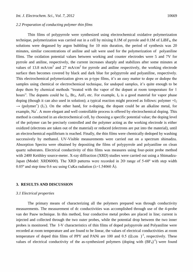
The energy band gap of these polymers has been calculated with the help of absorption spectra.
To calculate the optical band gap energy from absorption Spectra, the tauc relation is used [33]
α hν = A [ hν – Eg ]n ---------------(1)
where hν is the photon energy, h is Planck’s constant, α is the absorption Coefficient, Eg is the
optical energy gap, A is the constant, for direct transitions n=1/2. We plot a graph between (α hν)2
versus hν, the extrapolation of the straight line to (αhν)2 = 0 axis gives Eg. Figure 7 shows the plots of
(αhν)2 versus hν for the polypyrrole and polyaniline doped with (BF4)
-1, respectively. The values of Eg
obtained for doped polypyrrole and polyaniline are 1.75 and 1.60 eV, respectively.
1.20 1.60 2.00 2.40 2.80
Photon Energy (eV)
0.00E+0
1.00E+7
2.00E+7
( h
)
0.00E+0
4.00E+5
8.00E+5
( h
)
2
PANi PPY+
Figure 7. Plot of (hν) 2
vs. hν for for thin films of PPY and PANi
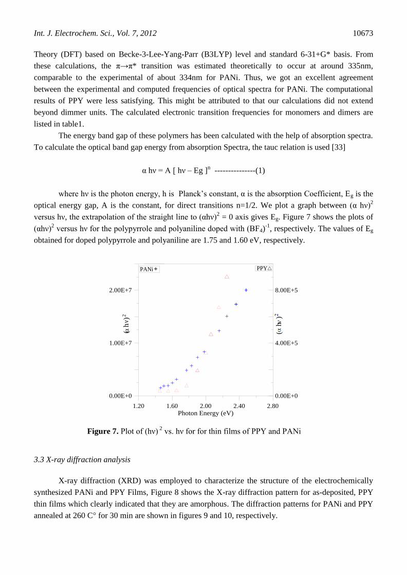
3.3 X-ray diffraction analysis
X-ray diffraction (XRD) was employed to characterize the structure of the electrochemically
synthesized PANi and PPY Films, Figure 8 shows the X-ray diffraction pattern for as-deposited, PPY
thin films which clearly indicated that they are amorphous. The diffraction patterns for PANi and PPY
annealed at 260 C° for 30 min are shown in figures 9 and 10, respectively.

Int. J. Electrochem. Sci., Vol. 7, 2012
10674
Figure 8. XRD Patterns of PPY thin films as-deposited
0.00 20.00 40.00 60.00
0.00
100.00
200.00
300.00
Inte
nsity
Figure 9. XRD Patterns of PANi thin Film (annealed at 260 Cº)
These figures indicates that the annealed films partially crystalline, the pattern of PANi film
includes three prominent broad peaks and few smaller peaks riding over a broad hump, indicating that
chain ordering is predominantly limited to short range.
The broad peaks observed at about 2θ =12º and 24.6º are similar to those observed by other
workers [56, 57]. The other peaks located at 2θ =38º and 44.7º and the first 2 peaks are also similar to
those mentioned in literature [58, 59]. The diffraction pattern of PPY thin film shows a peak at about
2θ = 12º [60], and a hump around at 2θ = 24º which is typical for conducting amorphous polymer
polypyrrole [61, 62].
Int. J. Electrochem. Sci., Vol. 7, 2012
10675
0.00 10.00 20.00 30.00 40.00 50.00
0.00
100.00
200.00
300.00
400.00
Figure 10. XRD Patterns of PPY thin Film (annealed at 260 Cº)
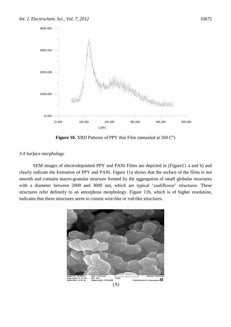
3.4 Surface morphology
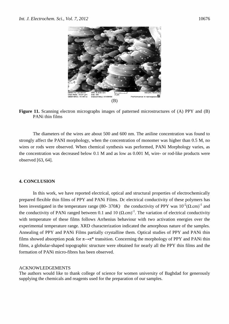
SEM images of electrodeposited PPY and PANi Films are depicted in (Figure11 a and b) and
clearly indicate the formation of PPY and PANi. Figure 11a shows that the surface of the films is not
smooth and contains macro-granular structure formed by the aggregation of small globular structures
with a diameter between 2000 and 3000 nm, which are typical ‘cauliflower’ structures. These
structures refer definetly to an amorphous morphology. Figure 11b, which is of higher resolution,
indicates that these structures seem to consist wire-like or rod-like structures.
(A)
Int. J. Electrochem. Sci., Vol. 7, 2012
10676
(B)
Figure 11. Scanning electron micrographs images of patterned microstructures of (A) PPY and (B)
PANi thin films
The diameters of the wires are about 500 and 600 nm. The aniline concentration was found to
strongly affect the PANI morphology, when the concentration of monomer was higher than 0.5 M, no
wires or rods were observed. When chemical synthesis was performed, PANi Morphology varies, as
the concentration was decreased below 0.1 M and as low as 0.001 M, wire- or rod-like products were
observed [63, 64].
4. CONCLUSION
In this work, we have reported electrical, optical and structural properties of electrochemically
prepared flexible thin films of PPY and PANi Films. Dc electrical conductivity of these polymers has
been investigated in the temperature range (80- 370K) the conductivity of PPY was 10-2
(Ω.cm)-1
and
the conductivity of PANi ranged between 0.1 and 10 (Ω.cm)-1
. The variation of electrical conductivity
with temperature of these films follows Arrhenius behaviour with two activation energies over the
experimental temperature range. XRD characterization indicated the amorphous nature of the samples.
Annealing of PPY and PANi Films partially crystalline them. Optical studies of PPY and PANi thin
films showed absorption peak for π→π* transition. Concerning the morphology of PPY and PANi thin
films, a globular-shaped topographic structure were obtained for nearly all the PPY thin films and the
formation of PANi micro-fibres has been observed.
ACKNOWLEDGEMENTS
The authors would like to thank college of science for women university of Baghdad for generously
supplying the chemicals and reagents used for the preparation of our samples.
Int. J. Electrochem. Sci., Vol. 7, 2012
10677
References
1. A. Rudge, J. Davey, I. Raistrick and S. Gottesfeld, J. Power Sources., 47 (1994) 89.
2. T. Shoa, J. D. Madden, C. E. Fok and T. Mirfakhrai, Adv. Sci. Tech., 61 (2008) 26.
3. D. C. Trivedi, in H.S. Lalwa (Ed.), Handbook of Organic Conductive Molecules and Polymers,
John Wiley & Sons, New York (1997).
4. A. G. MacDiarmid, Angew. Chem. Int. Ed. Engl., 40 (2001) 2581.
5. R. B. Kaner, Electrochem. Sci. Technol. Polym., Elsevier Science, New York (1990) 97.
6. F. N. Stephen, Li. Gaoquan and K. Asgeir, organic letters., 3 (2001) 1583.
7. H. Chon, S. I. Woo and S. -E. Park, Elservier Science B. V., 102 (1996) 304.
8. A. G. MacDiarmid, J. C. Chiang, A. F. Richter and A. J. Epstein, Synth Met., 18 (1987) 285.
9. E. M. Genes, A. Boyle, M. Lapkowski and C. Tsintavis, Synth Met., 36 (1990) 139.
10. A. O. Patil, A. J. Heeger and F. Wudl, Chem Rev., 88 (1988) 183.
11. P. Novak, K. Muller, K. Santhanam and O. Haas, Chem Rev., 97 (1997) 207.
12. W. P. Elizabeth, J. R. Antonio and M. S. Wrighton, J Phys Chem., 89 (1985) 1441.
13. Y. Guo,Y. Zhang, H. Liu, S. W. Lai, Y. Li, Yu. Li, Wo. Hu, S. Wang, C. M. Che and D. Zhu, J.
Phys. Chem. Lett., 1 (2010) 327.
14. S. Bereznev, J. Kois, I. Golovtsov, A. Opik and E. Mellikov, Thin Solid Films., 511–512 (2006)
425.
15. A. J. Heeger and J. long, Optics& photonic news., 7 (1996) 24.
16. G. Yu, J. Gao, J. C. Hummelen, F. Wudl and A. J. Heeger, Science 270 (1995) 1789.
17. Y. G. Wang, H. Q. Li and Y. Y. Xia, Adv. Mater., 18 (2006) 2619.
18. Z.R. Liu, J.R. Zhou, H.L. Xue, L. Shen, H.D. Zang and W.Y. Chen, Synth. Met., 156 (2006) 721.
19. Yu. Shuping, Xi. Mingjun, H. Kefei, W. Zhongming, Y. Wensheng and Z. Hong, Thin Solid
Films., 519 (2010) 357.
20. Li. Jing, Z. Lihua, Wu Yinghui, H. Yutaka, Z. Aiqing and T. Heqing, Polym., 47 (2006) 7361.
21. F. Yakuphanoglu, E. Basaran, B. F. Senkal and E. Sezer, J. Phys. Chem. B., 110 (2006) 16908.
22. E. M. Ronald, J. Electronic Materials., 15 (1986) 61.
23. H. Letheby, J Chem Soc., 15 (1862) 161.
24. A. F. Diaz and J. A. Logan, J Electroanal Chem., 11 (1980) 111.
25. A. G. MacDiarmid and A. J. Epstein, Chem Soc., 88 (1989) 317.
26. I. Bekri-Abbes and E. Srasra, J. Polym.Res., 18 (2011) 659.
27. A. G. MacDiarmid, J. C. Chiang, M. Halpern, W. S. Huang, S. L. Mu, L. D. Somasiri, W. Q. Wu
and S. I. Yaniger, Mol Cryst Liq Cryst., 121 (1985) 173.
28. A. D. Becke, J. Chem. Phys., 98 (1992) 5648.
29. J. B. Foresman, M. Head-Gordon, J. A. Pople and M. J. Frisch, J. Phys. Chem., 96 (1992) 135.
30. A. W. Ahmed, Irq. J. Chem. Petrol. Eng.,10 (2009) 57.
31. V. Bocchi and G.P. Gardini, J. Chem. Soc. Commun., (1986) 148.
32. R. B. Bjorklund and I. Lundstorm, J. Electron. Mater., 13 (1984) 211.
33. V. Shakatawat, N. Jain, R. Saxena, N. S. Saxena and T. P. Sharama, J. Optoelectron .Adv. M., 9
(2007) 2130.
34. M. N. Kumar, M. Nagabhooshanam, M. Anand Rao and M. Bhagvanth Rao, Cryst. Res. Technol.,
36 (2001) 309.
35. M. Leclerc, G. D. Aparno and G. Zotti, Synth Met., 55 (1993) 1527.
36. F. Zuo, M. Angelopoulos, A. G. Macdiarmide and A. J. Epstein, Phys Rev B., 36 (1987) 3475.
37. M. A. Chougule, S. G. Pawar, P. R. Godse, R. N. Mulik, S. Sen and V. B. Patil, Soft. Nanosci.
Letter., 1 (2011) 6.
38. A. Kobayashi, H. Ishikawa, K. Amano, M. Satoh and E. Hasegawa, J. Appl. Phys., 74 (1993) 296.
39. M. Gosh, A. Barman, A. K. Meikap, S. K. De and S. Chatterjee, Phys. Lett A., 260 (1999) 138.
40. V. Shaktawat, K. Sharma and N.S. Saxena, J. Ovonic Res., 6 (2010) 239.

Int. J. Electrochem. Sci., Vol. 7, 2012
10678
41. P. S. Abthagir and R. Saraswathi, Mater. Chem. Phys., 92 (2005) 21.
42. E. Buhks and I. M. Hodg, Chem. Phys., 83 (1985) 5976.
43. C. Basavaraja, N. R. Kim, E. A. Jo, R. Pierson, D. S. Huh and A. Venkataraman, Bull. Korean
Chem. Soc., 30 (2009) 2701.
44. M. B. Malino and K. Triyana, The 3rd
Asian Phys. Symp., (APS 2009) 73. Bandung, Indonesia.
45. E. E. Tanriverdi, A. T. Uzumcu, H. Kavas, A. Demir and A. Baykal, Nano-Micro Lett., 3 (2011)
99.
46. Y. Long, L. Zhang, Z. chen, K. Huang, Y. Yang, H. Xiao, M. Wan, A. Jin and C. Gu, Phys. Rev.,
B71 (2005) 165412.
47. Y. M. Lee, S. Y. Ha, Y. K. Lee, D. H. Suh and S. Y. Hong, Ind. Eng. Chem. Res., 38 (1999) 1917.
48. W. Yin and E. Ruckenstein, Synth. Met., 108 (2000) 39.
49. N. Kuramoto and A. Tomita, Polym., 38 (1997) 3055.
50. Y. Sun, M. Diarmid and A. J. Epstein, J. Chem. Soc. Chem.Commun., 7 (1990) 529.
51. B. C. Roy, M. D. Gupta, L. Bhoumik and J. K. Ray, Synth. Met., 130 (2002) 27.
52. Z. L. Wang, X. Y. Kong, Y. Ding, P. Gao, W. L. Hughes, R. Yang, Z. L. Wang, X. Y. Kong and Y.
Zhang, Adv. Funct. Mater., 14 (2004) 943.
53. H. Shiigi, M. Kishimoto, H. Yakabe, B. Deore and T. Nagaoka, Anal. Sci., 18 (2002) 41.
54. C. C. Bof Bufon, J. Vollmer, T. Heinzel, P. Espindola, H. John and J. Heinze, J. Phys. Chem., B
109 (2005) 19191.
55. M. R. Nabid and A. A. Entezami, J. Appl. Polym. Sci., 94 (2004) 254.
56. H. A. Gemeay, A. I. Mansour, G. R. El-Sharkawy and B. A. Zaki, Eur. Polym. J., 41 (2005) 2575.
57. H. Narayan, A. M. Montano, M. L. Hernandez, J.A. Hernandez, C. P. Gonzalez and C.A. Ortiz, J.
Mater. Environ. Sci., 3 (2012) 137.
58. S.A. Ghani and H. C. Young, J. Phys. Sci., 21 (2010) 81.
59. S. O. Vilelaa, M. A. Soto-Oviedob, A. P. Albersc and R. Faezd, Mater. Res., 10 (2007) 297.
60. L. M. Yee, A. Kassim, H.N.M. Ekramul Mahmud, A. M. Sharif and M. J. Haron, Malaysian J.
Anal. Sci., 11 (2007) 133.
61. J. P. Wang, Y. Xu, J. Wang, X. Du, F. Xiao and J. Li, Synth. Met., 160 (2010) 1826.
62. N. Z. Bohari, Z. A. Talib, M. A. Yunos and A. Kassim, Int. J. Phys. Sci.,7 (2012) 1670.
63. X. Lu, Y. Yu, L. Chen, H. Mao, L. Wang, W. Zhang and Y. Wei, Polym., 46 (2005) 5329.
64. J. Huang, S .Virji, B. H. Weiller and R. B. Kaner, J. Am. Chem. Soc.,125 (2003) 314.
© 2012 by ESG (www.electrochemsci.org)