optical measurement and interferometrysite.iugaza.edu.ps/aabuzarifa/files/metro20152_ch7.pdf ·...
TRANSCRIPT
© Oxford University Press 2013. All rights reserved.
Chapter 7
Optical Measurement and Interferometry
© Oxford University Press 2013. All rights reserved.

Optical measurement provides a simple, easy, accurate and reliable means for carrying out inspection and measurements in the industry
the projected image should be clear, sharp and dimensionally accurate.
Application of interference of light is of utmost interest in metrology
Lasers are also being increasingly used in interferometers for precision measurement.
Introduction
© Oxford University Press 2013. All rights reserved.

Optical magnification is one of the most widely used techniques in metrology.
the primary requirement is visual magnification of small objects to a high degree with the additional provision for taking measurements.
Optical Measurement Techniques
© Oxford University Press 2013. All rights reserved.
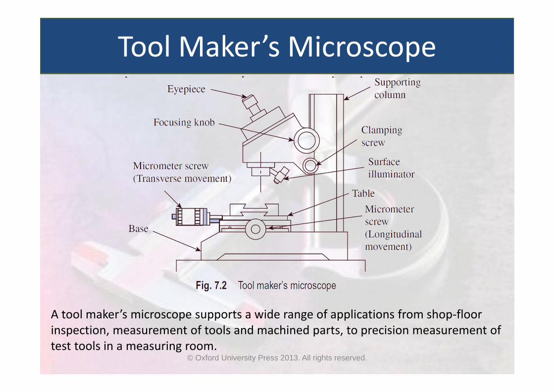
A tool maker’s microscope supports a wide range of applications from shop‐floor inspection, measurement of tools and machined parts, to precision measurement of test tools in a measuring room.
Tool Maker’s Microscope
© Oxford University Press 2013. All rights reserved.

It features a vertical supporting column, which is robust and carries the weight of all other parts of the microscope
The work‐piece is loaded on an XY stage, which has provision for translatory motion in two principal directions in the horizontal plane
The entire optical system is housed in the measuring head
When the image is viewed through the eye‐piece, a reticle provides the reference or datum to facilitate measurement
A surface illuminator provides the required illumination of the object, so that a sharp and clear image can be obtained
Tool Maker’s Microscope
© Oxford University Press 2013. All rights reserved.

An optical square is useful in turning the line of sight 90 degrees from its original path
The incident ray is reflected internally from two faces and emerges out of the square at exactly 900 to the incident light
Any slight deviation or misalignment of the prism does not affect the right angle movement of the light ray
Optical Squares
© Oxford University Press 2013. All rights reserved.
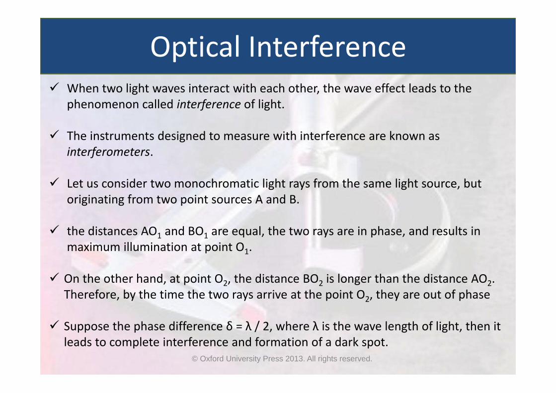
When two light waves interact with each other, the wave effect leads to the phenomenon called interference of light.
The instruments designed to measure with interference are known as interferometers.
Let us consider two monochromatic light rays from the same light source, but originating from two point sources A and B.
the distances AO1 and BO1 are equal, the two rays are in phase, and results in maximum illumination at point O1.
On the other hand, at point O2, the distance BO2 is longer than the distance AO2. Therefore, by the time the two rays arrive at the point O2, they are out of phase
Suppose the phase difference δ = λ / 2, where λ is the wave length of light, then it leads to complete interference and formation of a dark spot.
Optical Interference
© Oxford University Press 2013. All rights reserved.

This process repeats on either side of O1 on the screen, resulting in the formation of alternate dark and bright areas.
Optical Interference
© Oxford University Press 2013. All rights reserved.

The phenomenon of interference is made use of for carrying out precise measurements of very small linear dimensions, and the measurement technique is popularly known as interferometry.
This technique is used in a variety of metrological applications such as inspection of machine parts for straightness, parallelism, flatness, measurement of very small diameters, and so on.
Calibration and reference grade slip gauges are verified by interferometry technique.
The instrument used for making measurements using interferometry technique is called an interferometer.
Interferometry
© Oxford University Press 2013. All rights reserved.
Optical Flats
© Oxford University Press 2013. All rights reserved.

© Oxford University Press 2013. All rights reserved.
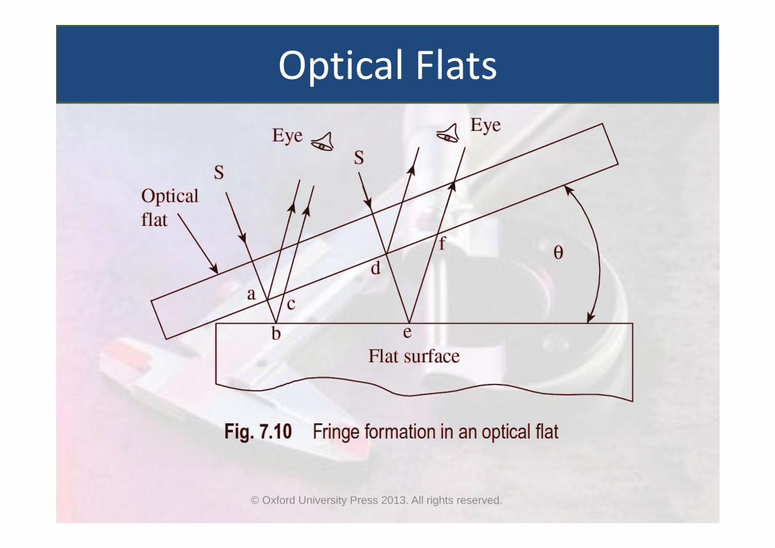
Optical Flats An optical flat is a disk of high quality glass or quartz
When an optical flat is laid over a flat reflecting surface, it orients at a small angle θ, because of the presence of air cushion between the two surfaces.
When light from a monochromatic light source is made to fall on an optical flat, which is oriented at a very small angle with respect to a flat reflecting surface, alternate band of light and dark patches are seen by the eye
In case of a perfectly flat surface, the fringe pattern is regular, parallel and uniformly spaced. Any deviation from this pattern is a measure of error in the flatness of the surface being measured

Comparative Measure with Optical Flats
© Oxford University Press 2013. All rights reserved.

Whereas an interferometer works on the same basic principle as that of an optical flat, it is provided with arrangements in order to control the lay and orientation of fringes.
It is also provided with a viewing or recording system, which eliminates the measurement errors.
Interferometers
© Oxford University Press 2013. All rights reserved.
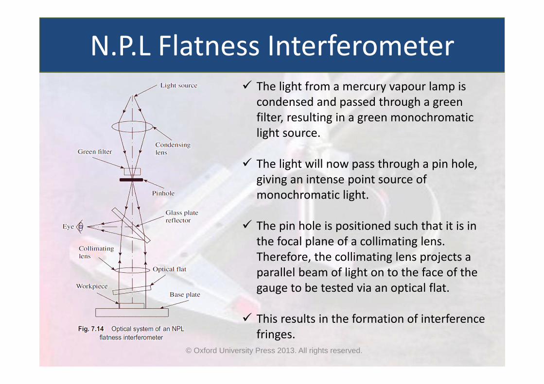
The light from a mercury vapour lamp is condensed and passed through a green filter, resulting in a green monochromatic light source.
The light will now pass through a pin hole, giving an intense point source of monochromatic light.
The pin hole is positioned such that it is in the focal plane of a collimating lens. Therefore, the collimating lens projects a parallel beam of light on to the face of the gauge to be tested via an optical flat.
This results in the formation of interference fringes.
N.P.L Flatness Interferometer
© Oxford University Press 2013. All rights reserved.

This interferometer is used for determining actual lengths of slip gauges. Since the measurement calls for high degree of accuracy and precision, the instrument should be used under highly controlled physical conditions.
Pitter – N.P.L. Gauge Interferometer
© Oxford University Press 2013. All rights reserved.

Interference fringes can be observed with a light intensity that is 1000 times morethan any other monochromatic light source.
Laser Interferometers
© Oxford University Press 2013. All rights reserved.

In interferometry, laser light exhibits similar properties as that of any ‘normal’ light.
The fixed unit called the laser head consists of laser, a pair of semi‐reflectors and two photo‐diodes. The sliding unit will have a corner cube mounted on it.
The corner cube is a glass disk whose back surface has three polished faces mutually at right angles to each other.
The corner cube, thus, will reflect light by 1800, regardless of the angle at which light is incident on it.
The photo‐diodes will electronically measure the fringe intensity and provide an accurate means for measuring displacement.
Laser Interferometers
© Oxford University Press 2013. All rights reserved.

Scales Typically involve a readout system in which an index point is moved
mechanically until it frames the scale line and thereby reads the amount of movement that has taken place
In more advanced optical instruments, photoelectric scale viewing systems are preferred. They enable more precise settings, higher speed and remote viewing.
The reading of the scale is accomplished electronically. Photo‐detectors sense the differing light intensity as the scale divisions are moved across a stationary photo‐detector.
Scales with continuously repeating pattern of lines or groves, which are more closely spaced, are called reticles.
Scales, Gratings and Reticles
© Oxford University Press 2013. All rights reserved.
There are two types of gratings; the ‘Ronchi rulings’ and ‘phase gratings’.
Ronchi rulings consist of strips that are alternatively opaque and transmitting, with spacing of 300 to 1000 per millimetre.
The phase gratings consist of triangularly shaped, contiguous grooves similar to spectroscopic diffraction gratings.
The main element that makes a microscope a measuring instrument is the reticle. It provides a reference in the form of cross‐wires for taking measurements.
The cross‐wires, sometimes also called as ‘cross hairs’ are usually etched on glass and fitted to the eye‐piece of the microscope.
Scales, Gratings and Reticles
© Oxford University Press 2013. All rights reserved.

A variety of reticles are used with microscopes for precise setting to measure part features. Figure illustrates four types of reticles, which are normally used.
Scales, Gratings and Reticles
© Oxford University Press 2013. All rights reserved.