optical networking for quantum key distribution and quantum
TRANSCRIPT

Optical Networking for Quantum Key Distribution and Quantum Communications
T E Chapuran1, P Toliver1, N A Peters1, J Jackel1, M S Goodman1,5, R J Runser2, S R McNown2, N Dallmann3, R J Hughes3, K P McCabe3,J E Nordholt3, C G Peterson3, K T Tyagi3, L. Mercer4 and H. Dardy4
1Telcordia Technologies, One Telcordia Drive, Piscataway, NJ 08854, USA2 Laboratory for Telecommunications Sciences, College Park, MD 20740 USA3 Los Alamos National Laboratory, Los Alamos, NM 87545, USA4 Naval Research Laboratory, Washington D.C., USA 20475
E-mail: [email protected]
Abstract. Modern optical networking techniques have the potential to greatly extend the applicability of quantum communications by moving beyond simple point-to-point optical links, and by leveraging existing fibre infrastructures. We experimentally demonstrate many of the fundamental capabilities that are required. These include optical-layer multiplexing, switching, and routing of quantum signals; quantum key distribution (QKD) in a dynamically reconfigured optical network; and coexistence of quantum signals with strong conventional telecom traffic on the same fibre. We successfully operate QKD at 1310 nm over a fibre shared with four optically amplified data channels near 1550 nm. We identify the dominant impairment as spontaneous anti-Stokes Raman scattering of the strong signals, quantify its impact, and measure and model its propagation through fibre. We describe a quantum networking architecture which can provide the flexibility and scalability likely to be critical for supportingwidespread deployment of quantum applications.
1. IntroductionThe ultimate usefulness of most communications services depends strongly on the ability to network, i.e., to efficiently connect many end users with each other or with shared resources. Much of the experimental research on Quantum Key Distribution (QKD) has focused on improving transmission performance over a fixed end-to-end connection between a single pair of quantum endpoints, Alice and Bob. However, this type of connectivity does not scale well,because the level of resources that are required increases very rapidly with the number of end users. Efficient networking solutions are clearly needed to move QKD and other types of quantum communications beyond the realm of niche deployments.
Many of the technologies, components and techniques needed to address these problems have been developed over the past quarter century for use in conventional optical fibre networks. Early fibre networks utilized optics solely for point-to-point (PTP) transmission between opaque nodes, in which all networking functions were implemented electronically. In contrast, modern fibre networks increasingly take advantage of optical transparency, in which a subset of critical networking functions such as switching, routing and multiplexing are preferentially performed in the optical layer [1]. This enables the establishment of multiple optically transparent lightpaths through a network domain, and highly dynamic re-routing or reconfiguration of these lightpaths. Applied to QKD, optical networking offers the prospect of flexible and scalable on-demand connectivity for a large number of Alice-Bob pairs. End-to-end key establishment over an untrusted network is feasible for lightpaths compatible with the maximum attenuation allowed
5 Current address: DARPA/DSO, 3701 North Fairfax Dr., Arlington VA 22203; work performed while affiliated with Telcordia

by the QKD system. Communications over longer end-to-end paths, or between endpoints with incompatible QKD systems, can be routed on demand via a shared set of ‘trusted relay’ nodes in secured locations [2-8]. The network can also provide endpoints with optically transparent access to other shared resources, such as ‘centralized’ entangled-photon sources for QKD. Finally, optical networking offers the prospect of leveraging costly infrastructure already deployed for telecom and enterprise networks, via wavelength-division multiplexing (WDM) of quantum and conventional data signals onto the same fibres. A central question for the future of QKD is to what extent it can attain wide applicability by taking advantage of these major advances in conventional optical networking.
Achieving this vision requires developing new capabilities, and validating them in realistic network environments. In this paper, we experimentally demonstrate a number of fundamental capabilities of optical networking as applied to QKD. These include optical routing, automated restoration after network path reconfiguration, and multiplexing and transmission of QKD with strong conventional WDM channels on the same fibre. We also examine practical considerations for applying optical networking architectures and technologies to QKD, and resulting impacts on the quantum signals in these environments. Although the experiments and analyses reported in this paper focus entirely on QKD, many of the results are likely to also carry implications for a broader range of quantum communications services which rely on the transport of photonic qubits over fibre networks.
The earliest QKD optical networking experiments were reported by Townsend’s group [9-10], which measured quantum bit error rates (QBER) for QKD signals transmitted through a 1:3 passive optical splitter to facilitate distribution of QKD signals to three different receivers. Following this work, several additional groups proposed passive fibre distribution networks to transmit key to multiple nodes [11-13]. Our group reported the first demonstrations of QKD through optical switches, including key establishment through several types of switch fabrics, and optical protection switching between two fibre paths connecting Alice and Bob [14]. Honjo et al. used a planar lightwave circuit (PLC) switch to connect Alice with either of two Bobs, demonstrating low QBER in the presence of crosstalk from a much stronger channel on a different path through the switch [15]. Optical switching has also been used in a portion of the DARPA quantum network [8], and investigated in a three-node QKD configuration at NIST [16].
The first experiment using WDM to combine QKD with an uncorrelated data channel on the same fibre was reported by Townsend [17]. WDM is often employed for carrying ‘bright’ synchronization pulses along with the quantum signals, and has occasionally been used to support one or a small number of data channels. However, few experiments have reflected the environments encountered in routing quantum signals through a modern telecom or enterprise network, in which very strong (~1 mW) data channels create substantial impairments which must be understood and mitigated. Early work with multi-channel WDM can be found in [18, 19] and [20], for QKD signals near 1310 nm or 1550 nm, respectively.
Our approach differs from, but is complementary with, the ‘trusted relay’ backbone architecture demonstrated by the SECOQC collaboration [2-4], and related approaches [5] which build on concepts developed for the DARPA quantum network [6-8]. For example, the SECOQC network is constructed from a collection of fixed PTP QKD links, with a variety of QKD technologies, connecting opaque quantum nodes in secured locations. Networking functions are performed entirely in the electronic domain, in a trusted network dedicated to QKD.
The following section provides a brief overview of the role of optical networking in quantum communications. Section 3 presents experimental results on the operation of QKD in dynamically reconfigurable networks, while Section 4 reports results on combining QKD with strong data channels in shared network environments. Section 5 provides a summary and conclusions.

2. The Role of Optical Networking in Quantum CommunicationsThe value of communications depends strongly on the number and variety of endpoints that are accessible. For example, for peer-to-peer applications such as voice calls, file transfers, or QKD sessions between a pair of end users, Metcalfe’s Law suggests that the value of the service is roughly proportional to the square of the number of users that can be interconnected. The value of shared resources on a network such as Web servers, key servers, or entangled photon sources, also depends strongly on the number and variety of end users to which access can be provided. Optical fibre is the most practical way to reach a large number of endpoints, whether end users or servers; however, static PTP fibre connections are not scalable to large numbers of endpoints. Efficiently interconnecting these endpoints is an optical networking problem.
Quantum communications can take advantage of the technologies, components and architectures developed over the past two decades for conventional fibre communications. Figure 1 provides a schematic overview of two different types of reconfigurable quantum communications networks. The boxes labelled A and B represent quantum endpoints (Alices and Bobs) at a variety of locations. The cloud on the left represents a network domain dedicated entirely to quantum-based services. (In addition to quantum signals, this network might also carry a small number of directly related classical signals, e.g. the ‘public’ reconciliation channels forQKD.) The cloud on the right represents a shared network domain, in which quantum channels are wavelength multiplexed onto fibres carrying conventional optical data traffic in a typical large telecom (carrier) or enterprise (private business) network. Within each of the two clouds, the endpoints are interconnected by a mesh of optical routers. These could be simple fibre switches, wavelength-selective switches, or other existing devices capable of independently routing wavelengths through the node. An important point is that these routers are optically transparent, and do not themselves originate or terminate quantum signals. The quantum signals are transmitted transparently end-to-end between Alice and Bob. As a result, the optical routers themselves need not be trusted or physically secured.
Optical Router
A1
WDM
A2
WDM
A3
WDM
B2
WDM
B3
WDM
B1
WDM
Processing Node
Dedicated to Quantum Shared Quantum and Telecom
Inter-Network LinkEntangled
PhotonSource GW
GW
Gateway
Gateway
A2
B1
B2
B3
A1
A3
Optical RouterOptical Router
A1
WDM
A2
WDM
A3
WDM
B2
WDM
B3
WDM
B1
WDM
A1
WDM
A2
WDM
A3
WDM
B2
WDM
B3
WDM
B1
WDM
A1
WDM
A2
WDM
A3
WDM
B2
WDM
B3
WDM
B1
WDM
Processing Node
Dedicated to Quantum Shared Quantum and Telecom
Inter-Network LinkInter-Network LinkEntangled
PhotonSource GW
GWGWGW
GW
Gateway
Gateway
A2
B1
B2
B3
A1
A3
A2
B1
B2
B3
A1
A3
Figure 1. Schematic view of two types of reconfigurable optical network domains. See text for discussion.
Within each network domain, the optical layer provides some of the networking functionality, rather than simply PTP transmission as in the trusted relay model. The optical routing and multiplexing are electronically controlled, and can be dynamically reconfigured as needed. This provides flexible, optical layer on-demand connectivity between any Alice and any Bob in the domain (within the range limitations of the quantum signals for the particular service

being provided, e.g., QKD). It also avoids the scalability problems associated with dedicated connections for every Alice-Bob pair. In addition, reliability is enhanced by the ability to optically reroute signals along alternate paths in the case of network failures, congestion, or high error rates due for example to noise or other interference.
Optical-layer reconfigurability also provides end users with transparent access to shared resources, such as ‘centralized’ entangled photon sources for on-demand entanglement-based QKD. Processing nodes, including trusted relays, can similarly be placed on the network and accessed on an as needed basis, for example to extend QKD range or to interface between incompatible quantum transmission systems.. It has been correctly stated that transparent optical networks do not increase the range of QKD, and in fact decrease it somewhat due to attenuation in the additional optical components required for networking functionality [3,8]. However, the choice is not restricted to fully transparent networks versus fully opaque networks. Modern fibre networks utilize a judicious combination of transparent networking and shared intermediate nodes (e.g., digital regenerators for classical optical signals). This hybridized approach has the potential to significantly reduce the number of opaque nodes required, along with the associated cost, complexity, and potential security requirements.
Large communications networks are almost invariably constructed from sub-networks or administrative domains, such as the two clouds shown in figure 1, for reasons of scalability and manageability. A limited number of gateways in each domain are used for interconnection and routing of traffic among the various domains. Optical reconfigurability between endpoints and gateways supports efficient aggregation of traffic headed for other domains (e.g., over the inter-network link in figure 1), and efficient distribution of traffic upon its arrival. This hierarchical approach is characteristic of communications networks, with different architectures and technologies in the access, metro, and core (long-haul) regimes, driven by different distance scales, traffic patterns, and cost considerations. In the quantum realm, for example, inter-network links could involve different types of fibre-based implementations, chains of quantum repeaters, or free-space links. Gateways provide the necessary adaptations, and often play an important role in securing communications entering or leaving a domain. For these reasons, gateways are natural locations for secured opaque processing nodes needed to support quantum services.
The advantages of reconfigurable optical networks apply to both ‘dedicated’ and ‘shared’ network domains of the type indicated in figure 1. However, shared quantum/telecom networks bring the additional prospect of leveraging hundreds of billions of dollars of investment in embedded infrastructure, which could be a critical enabler for quantum communications.
3. QKD in Dynamically Reconfigurable Fibre NetworksOne of the most fundamental elements of networking is the ability to route signals along chosen paths through multiple network links. Routing can be classified as static or dynamic, depending on the time scale or the level of effort involved in changing routes. We focus in this section on dynamically reconfigurable approaches, for example electronically controlled switches and multiplexers, as opposed to manual reconfiguration of fibres, filters, or wavelength-selective routing components. Per-fibre routing can be performed using a variety of all-optical switching technologies. Dynamic per-wavelength routing in a multi-wavelength environment typically utilizes a combination of optical switching with wavelength multiplexing and demultiplexing.
Our group reported the first tests of QKD through transparent optical switching fabrics[14]. This included successful secret key establishment through a 4 x 4 switch based on 2D micro-electromechanical systems (MEMS) technology, which is widely utilized today, as well as through lithium niobate (LiNbO3) and opto-mechanical devices. We also later established QKD keys through a commercial network element with a 128 x 128 matrix of 3D-MEMS switches [18]. More recently, we have reported the first demonstration of QKD through a reconfigurable optical add drop multiplexer (ROADM), a network element combining multiplexing and MEMS switching for per-wavelength routing in the 1.5 m fibre transmission window [21].

Transparent optical switching, originally developed for conventional telecom networks, thus makes it feasible to route qubits through a fibre network between a pair of quantum endpoints. Dynamic reconfigurability also supports other important networking functions such as optical protection switching, which is heavily deployed to reroute signals past fibre cuts or failed equipment. We have previously demonstrated a QKD application of the widely deployed 1+1 optical protection architecture [22]. Alice’s QKD signals were sent through a 50:50 optical power splitter into two separate fibre paths to Bob’s location, where a 2 x 1 opto-mechanical switch was used to manually select either of the two arriving signals to achieve the lowest bit error rate [14].
The dynamically reconfigurable optical networking architectures in figure 1 place additional demands on QKD systems, compared with PTP or statically routed fibre paths. In particular, a practical QKD system for this environment needs to be able to automatically respond to network path reconfiguration, which can produce substantial changes in the attenuation, time delay, and polarization state of the signals arriving at Bob’s location6. A new ‘network-friendly’ fibre-based QKD system was developed for experiments in optical networking environments [23]. This system is known as ‘F3’ because it is the 3rd generation of fibre QKD systems developed at Los Alamos. F3 is a weak-coherent pulse, one-way, phase-encoded design, performing the BB84 protocol [24] and transmitting at 1550 nm. It utilizes InGaAs avalanche photodiodes (APDs) cooled to 210 K and operated in Geiger mode, with a clock rate of 10 MHz and afterpulse blocking (set to 40 s for these experiments). The APDs were Epitaxx model EPM239BA, with detection efficiencies of approximately 21% and dark count probabilities per ns of ~2x10⁻⁵ to 3x10⁻⁵ at operating bias. F3 incorporates a full suite of protocols, including, error correction [25], privacy amplification [26], and authentication [27] which is particularly important in fibre-based QKD. In addition, F3 incorporates a number of new features to improve performance, stability and robustness in networking environments [23].
Day 1 Day 2 Day 3
Sifted bit rate
Secret bit rate
QBER
Day 4
Q
Day 1 Day 2 Day 3
Sifted bit rate
Secret bit rate
QBER
Day 4Day 1 Day 2 Day 3
Sifted bit rate
Secret bit rate
QBER
Day 4
Q
Figure 2. Automated operation of F3 1550 nm QKD system over a static 25 km in-ground network fibre path, dedicated to QKD. See text for discussion.
6 While fibre-based QKD systems most often employ phase encoding of the qubits, the optical phase modulator at Bob usually is polarization dependent, and reduces system throughput if the incoming photons are not appropriately aligned.

The F3 QKD system is software controlled, highly automated, and uses adaptive control to respond to sudden and/or slowly varying changes in the network environment [23]. Figure 2 provides an example of data obtained over a 25-km round trip path through a portion of the ATDNet transparent optical networking tested [28], between Adelphi MD and College Park MD. The quantum signals travelled over a dedicated, static in-ground fibre path in this experiment with a total path loss, including connectors, of ~9 dB. The system was operated unattended over nearly four days, with an average of =0.2 photons per pulse. To focus on the overall trends in the data, the display shows a moving average of 60 one-second QKD sessions. The average quantum bit error rate (QBER) and final secret key rate were 5.9% and 1090 b/s, respectively, during quantum transmissions. After accounting for overheads associated with system tuning, processing, and classical communications, a total of more than 38 million authenticated secret bits were shared between Alice and Bob. Despite slow drifts over time, the overall performance of the system was quite stable over the four-day period. The very strong anti-correlation of the QBER and secret bit rate curves, easily apparent in the data, reflects the behaviour expected asthe privacy amplification process accounts for variations in the quantum bit error rate.
The F3 system utilizes an auto-synchronization technique, using the quantum pulses themselves to align the timing of the detectors with the incoming photons [23]. Rubidium (Rb) oscillators are incorporated into Alice and Bob, providing a timing reference to automatically synchronize the detector gates with the arrival of the quantum channel pulses. At Bob, the detector gates are periodically swept in time, and a timing histogram is obtained of the detected events. The frequency of the Rb oscillator at Bob is tuned to maintain the phase-based QKDinterference pattern at a stable position, with sub-nanosecond accuracy. Large changes in the optical path length (frame offsets) can be established using a predetermined bit sequence sent from Alice to Bob. Thus F3 does not require a ‘bright’ synchronization pulse at a separate wavelength, as frequently used in QKD systems. This is a significant benefit for networking experiments and applications. It avoids any need to dedicate a valuable network wavelength for synchronization, or to require separate QKD and synchronization wavelengths to travel the same path through a wavelength-routed network. It also avoids timing shifts in the two signals due to chromatic dispersion when the (common) fibre path length is changed due to network reconfiguration. Quantum auto-synchronization also does not require dedicated time slots as in time-multiplexed approaches (with a bright pulse at the QKD wavelength), or a GPS antenna which may not always be available.
The ability of the F3 system to automatically respond to network path reconfiguration was investigated as shown in figure 3. Using two paths through a single 4 x 4 2D-MEMS switch, the QKD signals could be routed over three different fibre paths from Alice to Bob: a 10-km fibre spool, the 25-km network loopback route described earlier, and a direct (<5 m) fibre connecting the two endpoints. Each of the two passes through the switch increased the insertion loss by approximately 2.1 dB. The mean photon number was increased to = 0.4 for this experiment.
Figure 3 plots the secret bit rate and QBER as a function of time. Initially Alice and Bob were connected through the 10 km fibre spool, with an average QBER of 3.5% and a secret bit rate of roughly 3 kb/s. The route was then switched to the 25-km ATDNet path, and the QKD system automatically re-established synchronization and resumed key exchange after 19 minutes. Due to the large increase in attenuation and corresponding decrease in signal-to-noise ratio at Bob, keys were generated over the ATDNet link at a considerably lower rate and with a higher QBER. Finally the quantum channel was switched to the direct optical path, and the system automatically resynchronized, and resumed key exchange after 7 minutes. The final secret key rate was higher than along the original path due to the lower attenuation in the short fibre.

25kmATDNet
2D MEMS Switch 10km 2D MEMS Switch
UMCP
DirectF3
ALICEF3
BOB
10km ATDNet Direct
Re-syncTime
Re-syncTime
QBER7.5%
QBER3.5%
QBER3.5%
Sec
ret
Bit
Ra
te (
bit
s/s
ec)
1k
2k
3k
4k
Time
25kmATDNet
2D MEMS Switch 10km 2D MEMS Switch
UMCP
DirectF3
ALICEF3
BOB
10km ATDNet Direct
Re-syncTime
Re-syncTime
QBER7.5%
QBER3.5%
QBER3.5%
Sec
ret
Bit
Ra
te (
bit
s/s
ec)
1k
2k
3k
4k
Time
Figure 3. Automated QKD resynchronization after network path reconfiguration, using only the quantum channel.
To our knowledge, this was the first demonstration of QKD resynchronization following
network path reconfiguration using quantum clock recovery [29]. The QKD endpoints had no notification of the reconfigurations or the new path lengths, since none would be generated in the event of network protection switching or rerouting due to network maintenance. Upon reconfiguration, the fibre attenuation varied by as much as 9 dB, and the delay by as much as 125 s. The change in polarization state upon path reconfiguration was arbitrary and unpredictable. The results described above were obtained with an initial, non-optimized version of the software control algorithm, and we expect to be able to reduce the secret keying recovery time to less than 1 minute with improvements in the polarization tuning and re-timing routines.
A single Alice and Bob were used in this experiment, to simulate network path reconfiguration between fixed endpoints. However, the results indicate that a given Alice or Bob should be able to establish on-demand connections to a variety of partners on a dynamic reconfigurable network, without external synchronization channels.
4. Coexistence of QKD and Telecom Channels in Shared-Fibre NetworksDelivering quantum applications (or for that matter, any limited set of services) over a dedicated fibre network provides great flexibility, but also bears substantial cost penalties relative to conventional optical communications. Indeed, one of the major trends in communications in recent years has been to move services such as voice, data and video away from service-specific infrastructures, and onto converged networks. Over the past two decades the accessible bandwidth on a telecom fibre has increased by more than four orders of magnitude [1], due to a rapid increase in both data modulation rates and the number of wavelengths on a fibre. Large enterprises and governments, as well as telecom carriers, build or lease high-speed dense WDM (DWDM) networks [1]. This greatly increases the efficiency of fibre transmission, reducing the cost of providing a fixed bandwidth channel. However, the cost of the fibre infrastructure itself is
much less susceptible to sharp declines, because its installation is highly labour intensive. Utilizing conventional fibre networks for quantum communications provides an opportunity to leverage the large investment in existing infrastructure, and to reach the widest possible range of endpoints. However, shared networks also create major challenges due to the extremely large mismatch in optical power levels between classical and quantum channels.
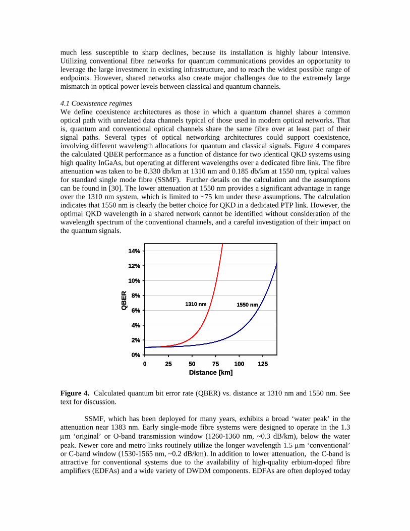
4.1 Coexistence regimesWe define coexistence architectures as those in which a quantum channel shares a common optical path with unrelated data channels typical of those used in modern optical networks. That is, quantum and conventional optical channels share the same fibre over at least part of their signal paths. Several types of optical networking architectures could support coexistence, involving different wavelength allocations for quantum and classical signals. Figure 4 compares the calculated QBER performance as a function of distance for two identical QKD systems using high quality InGaAs, but operating at different wavelengths over a dedicated fibre link. The fibre attenuation was taken to be 0.330 db/km at 1310 nm and 0.185 db/km at 1550 nm, typical values for standard single mode fibre (SSMF). Further details on the calculation and the assumptions can be found in [30]. The lower attenuation at 1550 nm provides a significant advantage in range over the 1310 nm system, which is limited to ~75 km under these assumptions. The calculation indicates that 1550 nm is clearly the better choice for QKD in a dedicated PTP link. However, theoptimal QKD wavelength in a shared network cannot be identified without consideration of the wavelength spectrum of the conventional channels, and a careful investigation of their impact on the quantum signals.
0%
2%
4%
6%
8%
10%
12%
14%
0 25 50 75 100 125
Distance [km]
QB
ER
1550 nm1310 nm
0%
2%
4%
6%
8%
10%
12%
14%
0 25 50 75 100 125
Distance [km]
QB
ER
1550 nm1310 nm
Figure 4. Calculated quantum bit error rate (QBER) vs. distance at 1310 nm and 1550 nm. See text for discussion.
SSMF, which has been deployed for many years, exhibits a broad ‘water peak’ in the attenuation near 1383 nm. Early single-mode fibre systems were designed to operate in the 1.3 m ‘original’ or O-band transmission window (1260-1360 nm, ~0.3 dB/km), below the water peak. Newer core and metro links routinely utilize the longer wavelength 1.5 m ‘conventional’ or C-band window (1530-1565 nm, ~0.2 dB/km). In addition to lower attenuation, the C-band is attractive for conventional systems due to the availability of high-quality erbium-doped fibre amplifiers (EDFAs) and a wide variety of DWDM components. EDFAs are often deployed today

in the longer metro-area links (e.g., >50 km). Optical amplifiers with comparable performance are not available in the O-band, and are not commonly used at these wavelengths. WDM is feasible but considerably less common in the O-band than in the C-band. Additional standard wavelength bands have been defined by the ITU-T [31], but are less frequently used in metro-area applications. Due to the long useful lifetimes of fibre and transmission systems, existing networks contain a mixture of fibre and equipment types with different vintage and performance (e.g., attenuation, chromatic dispersion, polarization effects), even along a single logical fibre path.
These considerations suggest several natural coexistence regimes. Placing QKD in the 1.3-m window leaves the 1.5-m band free for the DWDM designs typical of modern metro-area architectures. A second alternative is to carry both the QKD and classical signals in the 1.5-m band, for example using DWDM ROADMs for routing both types of traffic. A third approach would place QKD in the 1.5-m window, in older legacy systems where data traffic occupies the 1.3 m band. The region between the 1.3-m and 1.5-m transmission windows is also accessible in networks built entirely with modern fibres that have low water-peak absorption.
4.2 Coexistence of 1.3 m QKD with 1.5 m DWDM The earliest experiments which combined QKD signals and data on the same fibre were reported by Townsend [17], who multiplexed phase-modulated 1.3-m QKD signals with a single 1.5-m data channel over 28 km of installed fibre. However, no privacy amplification or yield of secret bits was reported. The received power in the data channel was varied from -50 dBm to -13 dBm, with error-free performance observed for power levels below roughly –29 dBm. With the received data channel power at this level, the impact on the error rate of the quantum channel was measured for three different data wavelengths. With the data channel tuned to 1505, 1551, and 1591 nm, the QBER was 22%, 6.5%, and 4% respectively. The strong wavelength dependence was attributed to the cooled Ge APD, optical components in the single-photon receiver, and the WDM demultiplexer, resulting in a rejection of 40 to 56 dB for the data channels. Townsend concluded that the performance was limited by out-of-band noise rejection (in the 1550-nm region). Our experiments demonstrate that sources of in-band noise (such as laser noise extending into the 1310 QKD region, and scattering effects) are also capable of producing serious limitations, and generally need to be carefully suppressed as well.
Our initial experiments utilized a particularly challenging data spectrum, consisting of high-power (+2 dBm total) EDFA-amplified DWDM signals produced by a commercial network element. This spectrum, shown in figure 5, included four amplified data channels, an optical supervisory channel (OSC), and a broad background from amplified spontaneous emission noise (ASE) generated by the EDFA. A lower noise region is visible below 1500 nm, although measurement sensitivity to extremely low noise levels is limited in this figure by the dynamic range of the optical spectrum analyzer (OSA).
We investigated coexistence with these signals by placing the QKD channel within the lower noise region of the spectrum, at 1310 nm. The experiments used a second-generation fibre QKD system from Los Alamos (F2), which was originally designed for point-to-point transmission [32]. The F2 QKD system is a one-way, phase-encoded, weak-coherent pulse design, operating the B92 protocol [33] at a clock rate of 100 kHz. Although B92 is not as secure as BB84, both protocols should respond similarly to the physical layer impairments which are the subject of this study. F2 utilizes a Fujitsu InGaAs APD detector cooled to 120 K and operated in Geiger mode, with an efficiency of ~11% and a dark count rate per ns of ~1 x 10⁻⁴ at operating bias. The system included the full set of QKD protocols, including error correction, privacy amplification [26] and authentication [27].

1300nm 1400nm 1500nm 1600nm
-110
-100
-90
-80
-70
-60
-50
-40
-30
-20
-10
0
10-4
10-3
10-2
10-1
100
101
102
103
104
105
106
107
Avg
. Po
wer [ph
otons
/ns]
Avg
. P
owe
r [d
Bm
]
Wavelength
1510 nmOSC
EDFAASE
Avg QKD Power Level @ 100 kHz rep rate
Low Noise Regionfor QKD
4 DWDM s
Figure 5. Optical spectrum analyzer plot of DWDM signals from a commercial network element, used for coexistence experiments with 1310-nm QKD. (The individual DWDM peaks are not
resolvable on this scale.)
The QKD power level was roughly -110 dBm, more than 11 orders of magnitude lower than the total DWDM spectral power; for reference, this is shown as a dashed line near the bottom of figure 5. Since average power is dependent on QKD transmission rate, the right vertical scale on the figure gives an alternative comparison in terms of photons per ns (corresponding to the ~1 ns detector gate widths used for InGaAs APDs). Within the amplification region of the EDFA, the ASE noise alone can produce hundreds of photons per detector gate, within each 0.1 nm resolution band of the optical spectrum analyzer, which would overwhelm the single-photon QKD signals. In addition, the detector’s efficiency is approximately independent of wavelength in this region, and it would integrate over the full spectrum presented to Bob. Extremely high rejection of the entire 1.5 m spectrum is thus needed at Bob’s receiver in order to operate in this environment.
The extremely large mismatch in optical power between the classical and quantum signals also means that QKD is susceptible to noise and impairments far smaller than those normally taken into account when designing conventional optical fibre networks. When a band cut-off filter was installed at the OSA input to suppress the strong 1.5 m signals and eliminate artifacts caused by them, the spectrum revealed roughly –69 dBm of noise (0.8 photons/ns) still remaining in each 0.1nm resolution band across a broad spectrum in the 1310-nm region. Even in systems without optical amplifiers, we found that 1.3-m in-band noise is readily produced by spontaneous emission tails from 1.5-m lasers operated at telecom power levels, generating prohibitively high background noise levels for QKD signals.
Successful extraction of the QKD signals thus requires pre-filtering of 1.3-m in-band noise generated by the conventional channels before Alice’s signals are multiplexed onto the fibreas well as post-filtering of 1.5-m out-of-band noise at Bob’s detector. Typically filter isolation of 30 to 40 dB is adequate for conventional WDM systems. However, in our experiments we used a low-loss, double-stage thin-film 1.3/1.5 m band multiplexer to provide >67 dB pre-filtering of

in-band noise at Alice (while combining the quantum and classical signals), and a double-stage band demultiplexer to obtain > 110 dB rejection of the out-of-band signals (while separating the quantum and classical signals) prior to Bob’s QKD detector. The total insertion loss of the multiplexer/demultiplexer pair was 2.4 dB. The complete experimental configuration is sketched in figure 6. The variable attenuator was used to adjust the launched power of the DWDM system, while the mean photon number at the output of Alice was fixed at =0.5. The purpose of the optional 1310 nm bandpass (BP) filter preceding Bob’s detector which will be discussed below.
Successful operation of QKD in the presence of the DWDM spectrum was first demonstrated over a short (<<1 km) fibre, with a secret bit rate of 500 bits/s and a QBER of 3.6%. The optional BP filter was not used for these measurements. As shown in figure 6, the performance was independent of whether the DWDM system was run at full power or turned off, indicating that the filtering architecture provided adequate noise suppression and isolation.
Transmission impairments, such as photon scattering and nonlinear interactions, can also be generated as signals travel through a fibre. Thus, it is important to investigate the interaction of classical and quantum channels over a range of relevant fibre lengths. In a second experiment, we inserted a 10 km fibre spool (3.4 dB insertion loss) into the path between Alice and Bob. The 10 km results are also shown in figure 6, both with and without the optional BP filter.
0
100
200
300
400
500
600
700
800
0 2 4 6 8 10 ∞Attenuation of WDM System [dB]
QK
D T
hro
ug
hp
ut
[Bit
s/s
ec]
1
n
EDFA15xx nmDWDM System
1
n
EDFAbandmux
banddemux
VarAtten
1310 nmQKD System Alice Bob
(QBER %)
Secret Yield(<< 1 km fiber)
(3.6%)QBER(3.6%)
(3.6%)Secret Yield (10 km fiber)
(7.5%)
10 km FiberLoss (3.4 dB)
1310 BP FilterLoss (2.2 dB)(4.4%)
Secret Yield w/BP Filter (10 km fiber)(4.3%)
Initial Key Bits (10 km fiber)
Anti-StokesScattered Light < 1410 nm
1310 nmBP Filter
<< 1km Fiber
Fiber
WDM SystemOFF
WDM SystemFull Power
0
100
200
300
400
500
600
700
800
0 2 4 6 8 10 ∞Attenuation of WDM System [dB]
QK
D T
hro
ug
hp
ut
[Bit
s/s
ec]
1
n
EDFA15xx nmDWDM System
1
n
EDFAbandmux
banddemux
VarAtten
1310 nmQKD System Alice Bob
(QBER %)
Secret Yield(<< 1 km fiber)
(3.6%) Secret Yield(<< 1 km fiber)
(3.6%)QBER(3.6%)QBER(3.6%)
(3.6%)(3.6%)Secret Yield (10 km fiber)
(7.5%)
Secret Yield (10 km fiber)
(7.5%)
10 km FiberLoss (3.4 dB)10 km Fiber
Loss (3.4 dB)
1310 BP FilterLoss (2.2 dB)1310 BP FilterLoss (2.2 dB)(4.4%)(4.4%)
Secret Yield w/BP Filter (10 km fiber)(4.3%)
Secret Yield w/BP Filter (10 km fiber)(4.3%)(4.3%)
Initial Key Bits (10 km fiber)
Initial Key Bits (10 km fiber)
Anti-StokesScattered Light < 1410 nm
Anti-StokesScattered Light < 1410 nm
1310 nmBP Filter1310 nmBP Filter
<< 1km Fiber
FiberFiberFiber
WDM SystemOFF
WDM SystemFull Power
Figure 6. Impact of fiber transmission on 1.3 m QKD/1.5 m DWDM coexistence.
With the 10 km fibre, but no BP filter in place, the secret key throughput with the DWDM system turned off (left-most point on the graph) was reduced from 500 to roughly 200 bits/s due to the additional 3.4 dB loss. However, as the DWDM system power was increased, QKD throughput dropped rapidly and the QBER rose to over 7.5%. No yield of secret bits was obtained with DWDM power above -2 dBm. The optical spectrum at the output of Bob’s 1.3-m band demultiplexer showed evidence of in-band broadband noise. The initial (sifted) key rate for the 10-km experiment actually increased with DWDM system power, which also can be indicative of an increased noise background. Since these effects were not observed in the short-fibre configuration, the noise appears to be the result of impairments generated in the 10-km fibre

spool. Due to the wide-band nature of the observed noise, a portion of it falls within the wide 1.3-m passband of the demultiplexer at Bob’s receiver.
To reduce the impact of this noise on QKD performance, a 1.5 nm BP filter centred at 1310 nm was added after the band demultiplexer. As shown in figure 6, the approximately 2.2 dB BP filter loss reduced the throughput in the 10-km configuration to 100 secret bits/s when the DWDM system was turned off. However, with the BP filter in place, no degradation in the throughput or the QBER was observed as the DWDM power was increased to its maximum level of +2 dBm. To our knowledge, this was the first demonstration of coexistence of QKD with strong multi-wavelength signals characteristic of a telecom environment [19].
Using the augmented filtering architecture, including the BP filter, the QKD throughput and QBER were measured for a short fibre (<< 1 km) as well as for transmission lengths of 10 km and 25 km, with the DWDM system alternately turned off or turned on at full power. These results, shown in Figure 7, show no observable impairment due to coexistence with the amplified DWDM system operating at full power, a common environment in modern metro-area networks.
Initial Key RateSecret Key RateInitial Key Rate+WDMSecret Key Rate+WDM (QBER)
1
10
100
1000
0 5 10 15 20 25
Distance [km]
Bit
s/se
c
(3.3%)
(4.6%)
(4.3%)
Initial Key RateSecret Key RateInitial Key Rate+WDMInitial Key Rate+WDMSecret Key Rate+WDMSecret Key Rate+WDMSecret Key Rate+WDM (QBER)
1
10
100
1000
0 5 10 15 20 25
Distance [km]
Bit
s/se
c
(3.3%)
(4.6%)
(4.3%)
Figure 7. Impact of fiber transmission on coexistence of 1310 nm QKD with a commercial amplified 1.5m DWDM system.
4.3 Transmission impairments in coexistence architectures Determining the origin of the noise background and its dependence on fibre length is critical for understanding under what circumstances coexistence is feasible. To further investigate these effects, 6 dBm of CW power from a 1550.9 nm laser was launched into 25, 50, 75 and 100-km lengths of SMF-28 fibre [19, 34]. The CW signal was pre-filtered to suppress the laser’s spontaneous emission noise below 1510 nm, with a rejection of ~50 dB. After transmission through the fibre spools, the signals were filtered to suppress the strong laser peak (by > 110 dB) so the noise spectrum below 1510 nm could be accurately measured with a highly sensitive OSA.
Figure 8 shows the OSA spectrum of the pre-filtered CW signal and the spectrum recorded at the output filter from the various fibre measurements. The approximate transfer function of the output filter is also shown. In the back-to-back case (0-km fibre), no measurable noise was generated below 1510 nm. However, as the fibre spans were inserted, a broad noise spectrum became clearly visible. The noise is strongest at the output of the 25-km fibre, and its magnitude is reduced over longer distances. Similar results were obtained for other fibre types, including non-zero dispersion shifted fibre (NZ-DSF) and large effective area fibre. The broad width, spectral shape, and magnitude of the noise are consistent with spontaneous Raman scattering of the light from the CW source [35].

DWDM ChannelQKD Channel
anti-Stokesscattering
DWDM ChannelQKD Channel
anti-Stokesscattering
Figure 8. Optical spectrum of a CW signal and the noise it generates in transmission through various lengths of SMF-28 fibre.
Raman scattering, in which light interacts with vibrational modes (optical phonons) in fibre, has been widely studied as a method of optical amplification. Raman amplifiers utilize a pump (or set of pump) wavelength(s) to provide gain to lower energy signal wavelengths through a stimulated Stokes Raman scattering process distributed throughout roughly 20 km of optical fibre. This process has also been studied as a fibre transmission impairment for DWDM systems, where signals themselves act as dynamic pumps that provide noisy gain to neighbouring wavelengths. These analyses concentrate on stimulated rather than spontaneous scattering, since the DWDM signal powers are significantly larger than the spontaneous scattering powers. However, the extremely low signal levels associated with QKD transmission can be less than the spontaneous Raman scattering background.
In Stokes Raman scattering, the incoming photon produces a lower energy photon and a phonon. In our experimental system, the DWDM (pump) channels are at a higher wavelength (lower energy) than the wavelengths of interest for the QKD channel. This is the domain of anti-Stokes Raman scattering, in which a pump photon interacts with an existing phonon, generating a higher energy scattered photon. The Stokes process is much more efficient than anti-Stokes, since it does not require the prior existence of a phonon. However, even for the anti-Stokes case, we observe spontaneously scattered noise levels in Figure 8 that are significant relative to the average QKD channel power. QKD channels can be placed only at wavelengths where this spontaneous anti-Stokes Raman noise (SASRN) level is well below the average QKD power.
The propagation of this noise level is of interest, as it will ultimately limit the fibre length over which coexistence is feasible. The general Raman pump-signal interaction is given by:
PSPSdz
dS
PSSPdz
dP
222
111
where P and S are the pump (DWDM) and signal (noise) powers, respectively, and , , and are the wavelength-dependent fibre attenuation, spontaneous Raman scattering coefficient, and stimulated Raman scattering coefficient, respectively. For the very low signal powers being considered here, the stimulated scattering terms (1PS and 2PS) and the spontaneous scattering

from signal to pump (1S) can all be neglected. The signal noise power can then be solved as a function of propagation distance z:
212
2112
2
1
21
)0(
)0()(
z
zz
zeP
eePzS
The attenuation spectra from each of the four 25-km spools of SMF-28 were calculated by measuring the input and output powers from a wideband optical noise source, assuming a spectrally constant connector loss. The spontaneous scattering coefficients for each spool were also calculated by applying a 6-dBm pump at 1550.92 nm to each spool individually, then using the measured spectral noise at S(25-km) to solve the above equations for 2. Verification of this model was accomplished by concatenating the spools, measuring the noise powers from each successive length (Figure 8), and comparing these values to those calculated from the equations above. Figure 9 shows good agreement between model and measurement at 3 different wavelengths, with some small differences attributed to measurement error for low measured SASRN powers. Note that SASRN power grows rapidly at first, and then decreases more slowly. At distances well past the peak of the function, the rate of decrease as a function of distance is determined by the lower of the attenuations at the pump and signal wavelengths (1 and 2, respectively). Note that although the absolute noise power from anti-Stokes Raman scattering reaches a peak for fibre lengths below 25 km (see figure 9), the QKD signal-to-noise continues to decrease monotonically with distance, since the 1310 nm signal is attenuated more rapidly than the 1550 nm pump.
-115
-105
-95
-85
-75
0 20 40 60 80 100
Distance (km)
SA
SR
N P
ow
er
(dB
m) Experimental MeasurementModel Result
1475 nm
1425 nm
1375 nm
Figure 9. Propagation of spontaneous anti-Stokes Raman noise (SASRN) through spools of SMF-28 fibre, at three different wavelengths.
Successful coexistence of QKD with amplified DWDM systems in the C-band requires an appropriate combination of wavelength separation and wavelength filtering, for fibres of length greater than a few kilometres. The extremely broad Raman spectrum extends on the order of 200 nm above and below the pump wavelength. For the QKD system and filtering architecture described above, and +6 dBm of launched power near 1550 nm, it has been shown that a wavelength separation of at least ~170 nm is needed [36]. An advantage of adopting such a wide channel spacing is that relatively simple, low cost filters can be utilized. With substantially narrower filters, or weaker classical signals, closer wavelength spacings would be feasible. However, for operation in typical telecom or enterprise network environments, it is critical to be

able to accommodate total classical signal strengths on the order of 0 dBm or above for transmission over tens of km.
4.4 QKD wavelengths for shared-fibre networksSection 4.1 identified three natural coexistence regimes for shared-fibre networks. Sections 4.2 and 4.3 have focused on the first of these regimes. Placing QKD in the 1.3-m window leaves the 1.5-m band free for the DWDM traffic typical of modern metro-area networks. We have shown that the dominant impairments are in-band spontaneous emission noise and Raman scattering from the strong conventional traffic. These effects are minimized by the large wavelength separation from the conventional channels, allowing the use of relatively simple, low-cost filtering architectures, even in the presence of node-based EDFAs. Similar filtering techniques have successfully been applied [30] to develop a quantum bypass for the mid-span EDFAs found in many fibre spans longer than 50 km. The primary disadvantage is the limited QKD range at 1310 nm (less than ~80 km with current APDs). Nevertheless, in many if not most cases, the 1.3-m window will be the most favourable location for QKD in a shared-fibre network, contrary to conventional wisdom.
Placing QKD in the 1.5-m band along with conventional traffic is most likely to be attractive when longer QKD range is essential. However, coexistence with optical amplifiers will be very difficult in such systems. The much stronger ASE and Stokes and anti-Stokes Raman scattering from nearby conventional channels is likely to require very high isolation, narrowband (~10 GHz) filters for noise suppression in WDM environments. In addition to Raman scattering, four-wave mixing (FWM) has been identified as a significant impairment [37] in such systems, and one that can depend strongly on the detailed channel plan for the conventional signals [21].
The advantage of longer QKD reach might be more easily achieved by carrying QKD in the 1.5-m window in older legacy systems, in which data traffic occupies the 1.3 m band. In this approach, the noise from Stokes Raman scattering will be greater than the anti-Stokes scattering reported above, for the same wavelength separation. However, the QKD signal-to-noise contribution from Raman Stokes scattering will decrease more slowly as a function of fibre length than in the 1310-nm QKD and 1550-nm data combination. QKD coexistence in the Raman Stokes regime is currently under experimental investigation in our laboratory.
5. Discussion and Conclusions Optical networking has the potential to greatly expand the applicability and usefulness of quantum communications by moving beyond simple point-to-point links, and by leveraging the large investment in existing optical fibre infrastructure. In a series of systematic investigations, we have demonstrated many of the fundamental capabilities required for taking advantage of optical networking techniques for QKD. These include optical-layer multiplexing, switching, and routing of QKD signals through a network; QKD operation in a dynamically reconfigurable optical network; and coexistence of QKD with strong (~0dBm) conventional telecom signals on the same fibre.
The networking approach described in this paper, which takes advantage of the optical layer, differs from but is complementary with ‘trusted relay’ architectures [2-8]. On its own, optical networking can support end-to-end key establishment over a completely untrusted network, within an appropriate metro-scale geographic range. It can also provide access to shared resources such as entangled photon sources and gateways to neighbouring or distant networks. When combined with trusted relays, it can reduce the number of secured intermediate quantum nodes that are required, while increasing the flexibility, scalability and reliability of connecting geographically scattered endpoints to a quantum backbone node. Optical networking also carries the potential for sharing existing telecom and enterprise infrastructure, a major economic advantage which could prove critical in increasing the adoption of quantum communications.

Modern optical networks are complex, hierarchical, and inhomogeneous systems. Understanding the feasible operating regimes for quantum communications, i.e., the domains of use for QKD and other quantum applications, will be critical for moving beyond niche applications, and towards widespread deployment. Although much work still remains to be done, the results reported in this paper represent an important step in this direction.
AcknowledgementsWe gratefully acknowledge that this work was supported by IARPA, and hosted by the Laboratory for Telecommunications Sciences.
References
[1] Berthold J, Saleh A A M, Blair L and Simmons J M 2008 J. Lightwave Tech. 26 1104
[2] Poppe A, Peev M and Maurhart O 2008 Int. J. Quant. Inf. 6 209
[3] Alléaume R et al. 2007 Preprint quant-ph/0701168v1
[4] Dianati M and Alléaume R, 2006 Preprint quant-ph/0610202v2
[5] Chen T-Y et al 2008 Preprint quant-ph/0810.1264v2
[6] Elliott C, 2002 New J. Phys. 4 46
[7] Elliott C, Pearson D and Troxel G 2003 SIGCOMM '03: Proc. of the 2003 Conf. on Applications, technologies, architectures, and protocols for computer communications (Munich) (New York: ACM) 227
[8] Elliott C 2006 Chapter 4 in Quantum Communications and Cryptography, ed. A V Sergienko (Boca Raton, FL: CRC Press) 83
[9] Townsend P D 1996 European Conf. on Optical Commun., WeB1.6
[10] Townsend P D 1997 Nature 385 47
[11] Nishioka T, Ishizuka H, Hasegawa T and Abe J 2002 IEEE Photon. Technol. Lett. 14 576
[12] Kumavor P, Beal A, Yelin S, Donkor E and Wang B 2005 J. Lightwave Tech. 23 268
[13] Fernandez V, Colins R J, Gordon K J, Townsend P D and Buller G S 2007 IEEE J. Quantum Electronics 43 130
[14] Toliver P et al 2003 IEEE Photon. Technol. Lett. 15 1669
[15] Honjo T, Inoue K, Sahara A, Yamazaki E and Takahashi H 2006 Optics Commun. 263 120
[16] Ma L, Chang T, Mink A, Slattery O, Hershman B and Tang X 2007 IEEE Com. Lett. 111019
[17] Townsend P D 1997 Electron. Lett. 33 188

[18] Goodman M S et al. 2003 IEEE Lasers and Electro-Optics Society 2003 (LEOS '03) 2 1040
[19] Toliver P et al. 2004 IEEE Lasers and Electro-Optics Society 2004 (LEOS '04) 2 491
[20] Xia T J, Chen D Z, Wellbrock G, Zavriyev A, Beal A C and Lee KM 2006 Optical Fiber Commun. Conf. OTuJ7
[21] Peters N A et al. 2008 submitted for publication.
[22] Telcordia Technologies 2006 Generic Requirement GR-1400-CORE
[23] Hughes R J et al 2005 Proc. SPIE 5893 589301
[24] Bennett C H and Brassard G 1984 Proc. IEEE Int. Conf. on Computers, Systems, and Signal Processing (Bangalore) (New York: IEEE) 175
[25] Brassard G and Salvail L 1994 Lecture Notes Comput. Sci. 765 410
[26] Bennett et al. 1992 J. Crypto. 5 3
[27] Wegman M N and Carter J L 1981 J. Comp. Sys. Sci. 22 265
[28] Runser R J, Toliver P and McNown S 2002 IEEE Lasers and Electro-Optics Society 2002 (LEOS '02) 2 407
[29] Runser R J et al. 2006 Opt. Fiber Commun. Conf. OFL1
[30] Runser R J et al. 2007 Proc. SPIE 6476 647601
[31] ITU-T 2002 Recommendation G.694.1
[32] Hughes R J, Morgan G and Peterson C 2000 J. Mod. Opt. 47 533
[33] Bennett C H 192 Phys. Rev. Lett. 68 3121
[34] Chapuran T E et al. 2005 Proc. SPIE 5815 164
[35] Mandelbaum I and Bolshtyansky M 2003 IEEE Photonics Tech. Lett. 15 1704
[36] Nweke N I et al 2005 Appl. Phys. Lett. 87 174103
[37] Toliver P et al 2007 Conference on Lasers and Electro-Optics (CLEO ’07) CaThBB1