optical slip-ring connector - open...
TRANSCRIPT

OPTICAL SLIP-RING CONNECTOR
Item Type text; Proceedings
Authors Xu, Guoda; Bartha, John M.; McNamee, Stuart; Rheaume, Larry;Khosrowabadi, Allen
Publisher International Foundation for Telemetering
Journal International Telemetering Conference Proceedings
Rights Copyright © International Foundation for Telemetering
Download date 02/05/2018 22:43:19
Link to Item http://hdl.handle.net/10150/607336

OPTICAL SLIP-RING CONNECTOR
Dr. Guoda XuPhysical Optics Corp.
John M. BarthaPhysical Optics Corp.
Stuart McNamee412TW/TSD
Larry Rheaume412TW/TSD
Allen KhosrowabadiTybrin Corp.
ABSTRACT
Current ground-based tracking systems at the DoD test and training ranges requiretransmission of a variety of signals from rotating platform to fixed control and processcenter. Implementation of commercial off the shelf (COTS) solution for transmitting high-speed, multiple-channel data signals over a rotational platform prompt the development ofan advanced electro-optic hybrid rotating-to-fixed information transmission technology.
Based on current demand, an Air Force-sponsored Small Business Innovative Research(SBIR) contract has been awarded to Physical Optics Corporation (POC) to modifyexisting tracking mounts with a unique electro-optic hybrid rotary joint (EOHRJ). TheEOHRJ under current development is expected to provide the following features: 1)include a specially designed electrical slip-ring, which is able to accommodate hundreds oftransmission channels, including electrical power, control, feedback, and low-speed datasignals; 2) include an optical fiber slip-ring which, by incorporating with electrical timedivision mulitplexing (TDM) and optical wavelength division multiplexing (WDM)technologies, is able to provide multiple channel, high data rate (over gigabits per second),

and bi-directional signal transmission; and 3) is designed to be reliable for harshenvironmental operation, adaptive to stringent size requirement, and accommodating toexisting electrical and mechanical interfaces.
Besides the military use, other possible commercial applications include on boardmonitoring of satellite spinners, surveillance systems, instrumentation and multi spectralvision systems, emergency/medical instruments, remote sensing, and robotics.
KEY WORDS
Electrical slip-ring, Fiber Optical Rotary Joint, Tracker SystemWavelength Division Multiplexing (WDM), and Time-Division Multiplexing (TDM)
INTRODUCTION
The current video tracker, Kineto Tracking Mount (KTM), is used at the DoD for rangesafety, fight vision, and other real-time applications. Most KTM systems use cable wrap orwaveguide rotary joints for transmission of electrical data, video and audio signals, andother information from numerous sensors on a rotating platform to control and processsystems at a fixed location. With the swift development of modern technology andapplications, there has been a tendency to add more sensors to existing mounts, whichresults in an increased number of data stream channels and an increased data rate for eachchannel in a data stream. For instance, in the current KTM system, more than 100 signalchannels, distributed from dc to radio frequency (RF) bands, be connected from a rotatingplatform to a fixed center. In addition, high definition color video and infrared sensors to beinstalled on future tracking systems generate high-rate data streams exceeding hundreds ofMbits per second (Mbps), even Gbits per second (Gbps). In order to make modern sensing,control, and processing systems operate accurately at highspeed, a reliable, speed-matched,rotating-to-fixed signal transmission technology is urgently needed.
At the moment, there are three available approaches being used to transmit electricalsignals from a rotating platform to a fixed position: 1) copper slip ring, 2) the cable wrapstructure, and 3) waveguide rotary joint. All three approaches required severe limitations onthe operational performance of rotational transmission systems. The copper slip ring canonly operate at relatively low speed, say, under 30 Mbps because many factors, such asphysical contact, moisture, and difficult impedance match, always put a limit on systemoperation speed. The cable wraps limits ability in continuous rotation without dropping thetracker and unwrapping the cables. This results in a limited angular tracking range. Mostcable wrap connectors used in existing military and civilian systems have to confine theirrotation in azimuth to about 540 degrees. Rotary waveguide joints are employed for signal

transmission through the axes of the waveguide mount, so their applications are limited onlyin radar and microwave antenna transmission systems.
The introduction of lightwave technology into today’s communication, computer, andsensor networks [1] for both military and industrial applications has spawned numerousnew phoptonic components that are smaller, lighter, faster, and more reliable than theirpurely electronic counterparts. Optics and photonics are gaining in popularity because oftheir intrinsic high-speed, high information volume, and immunity to electromagneticinterference (EMI). At the same time, they have become affordable. Based on currentdemand, an Air Force-sponsored Small Business Innovative Research (SBIR) contract hasbeen awarded to Physical Optics Corporation (POC) to develop a unique electro-optichybrid rotary joint (EOHRJ) for existing KTM systems application. The EOHRJ undercurrent development is expected to provide a number of unique features. First, it includes aspecially designed comprehensive electrical slip ring (ESR), which is capable ofaccommodating hundreds of transmission channels, including electrical power, control,feedback, and low-speed data signals. Second, it includes a state-of-the-art on-axis fiber-optic rotary joint (FORJ) which, by incorporating with electrical time division multiplexing(TDM) and optical wavelength division multiplexing (WDM) technologies, is able toprovide multiple channel, high data rate (over Gbps), and bi-directional signal transmission.Third, the EOHRJ, an integrated version of ESR and FORJ, is designed and fabricated tobe compact and adaptive to existing KTM space; rugged and reliable for harshenvironmental operation; and accommodating to existing electrical and mechanicalinterfaces. By closely working with user requirements, the future-developed EOHRJ will beincorporated into the current KTM system to improve its system function and performance.This paper presents our current joint work in this project. We first address our motivation inEOHRJ development. We then present the FORJ, including its architecture, majorfunctional parts, and initial testing results. The specially designed ESR to be integrated withFORJ and adapted to the existing KTM is then covered more completely. Finally, thepresentation is ended with application scenario and concluding remarks.
THE MOTIVATION OF ELECTRO-OPTIC HYBRID ROTARY JOINT (EOHRJ)DEVELOPMENT
Many current weapons systems use a variety of sensors and testing devices to monitor andmeasure systematic, environmental, and other operational factors. These sensors and testingdevices may operate in different frequency or wavelength bands, and in differentenvironmental conditions. What makes the task more difficult is that in many cases thesensors and testing devices are often distributed on a rotating platform and the receivedsignals have to be transmitted from the rotating platform at the testing field to a fixed pointat the command or process center. For example, Air Force’s current mobile optical KTMtracker systems are equipped with a number of optical and electrical sensing devices,

including high frame rate cameras. During the space test operation, the sensor platform hasto trace fast moving targets in both horizontal and vertical dimension, and send all types ofsignals to base center. At the same time, the electrical power, control, and command signalshave to be transmitted from base center to rotating platform. Presently, the function ofrotating to fixed (RTF) signal transmission is handled by a large number of electrical cables(nearly 200). The current use of wrap cables as RTF connectors has straightly limited therotating angle of the entire tracker system to 380 degrees. Whenever the angle is over thislimit, the wrapped cables have to be unwrapped to avoid breaking, which often lead tomissing a target, thus causing loss of time, money, and manpower. Furthermore, usingdiversified cables to transmit wide range of signals limits system operation speed to lessthan 100 Mbps. To overcome the above problems, a special and comprehensive rotaryjoint, which is capable of handling RTF transmission for all types of signals, is urgentlydemanded. It is motivated by this demand that the current program has been initiated. Theaim of the program is to develop a unique EOHRJ to replace all cable wrap joints and, atthe same time, furnish additional high-speed signal channels to the existing tracker system.Investigation continues for the following tasks to achieve this goal: 1) develop a uniqueFORJ, incorporated with electrical TDM optical WDM, to perform RTF function for high-speed signals (up to GBPS); 2) develop a special ESR to handle RTF function for all dc,low-speed, and high-power signals; and 3) generate a unique EOHRJ by integrating FORJwith ESR to complete the KTM system modification. Figure 1 shows the schematic of afuture KTM system, which will be equipped with POC’s EOHRJ.
Figure 1Future KTM System Equipped with EOHRJ
DEVELOPMENT OF AN ON-AXIS FORJFOR HIGH-SPEED SIGNAL RTF TRANSMISSION
Current KTM tracking platform is equipped with 35 mm model 4E cameras, that arecapable of frame rates of 6 to 360 frames per second (fps). The high frame rates allow forsuper slow motion examination of events such as weapons separations, parachutedeployment tests, load extractions, and munitions dispersals. In the near future, even higherspeed cameras (over 1,000 fps) will be used. These high-speed cameras generate videosignals with over GBPS data rate, such high data rate is impossible to be handled byexisting RTF structures. In order to overcome this bottleneck, an on-axis FORJ, which usescurrent advanced fiber optics and photonics technologies, has been investigated by POC.
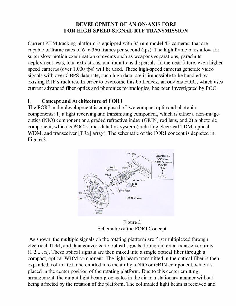
I. Concept and Architecture of FORJThe FORJ under development is composed of two compact optic and photoniccomponents: 1) a light receiving and transmitting component, which is either a non-image-optics (NIO) component or a graded refractive index (GRIN) rod lens, and 2) a photoniccomponent, which is POC’s fiber data link system (including electrical TDM, opticalWDM, and transceiver [TRx] array). The schematic of the FORJ concept is depicted inFigure 2.
As shown, the multiple signals on the rotating platform are first multiplexed throughelectrical TDM, and then converted to optical signals through internal transceiver array(1.2,..., n). These optical signals are then mixed into a single optical fiber through acompact, optical WDM component. The light beam transmitted in the optical fiber is thenexpanded, collimated, and emitted into the air by a NIO or GRIN component, which isplaced in the center position of the rotating platform. Due to this center emittingarrangement, the output light beam propagates in the air in a stationary manner withoutbeing affected by the rotation of the platform. The collimated light beam is received and
Figure 2Schematic of the FORJ Concept

focused back to a single optical fiber by the second NIO or GRIN component. The receivedlight is carried to the second WDM component, where the optical signals (1,2, …, n) aredemultiplexed and sent to the command base for detection, electrical time divisiondemultiplexing, and further signal processing. In this way, multichannel signals from arotating platform can be transmitted to the fixed ground center. Following a similar process,the signals from the ground center can be transmitted to the rotating platform, because theoptical components involved in this FORJ system (optical fiber, NIO or GRIN lens, WDM,and optical transceivers) are all bi-directionally operable. Therefore, not only can thecontrol center receive sensed signals from rotating platform for monitoring and processing,but it can also send signals (such as actuator command, switching, or feedback signals)back to any one of the sensor arrays for controlling. In addition, because all the above-mentioned optical components are able to carry or handle over GBPS signals, the FORL setinherently provides high data rate capability.
II. Major Functional Components for FORJThe on-axis FORJ is designed to be small, compact, and rugged, it consists of opticalfibers, a pair of NIO or GRIN components, and a pair of POC’s fiber data link sets whichinclude electrical TDM, optical WDM, and electro-optic transceivers. We now brieflyintroduce the most important functional components: NIO and GRIN lens, electrical TDM,optical WDM, and POC’s fiber optic data link system.
1. Non-Imaging-Optic (NIO) ComponentsPrinciple: Unlike conventional lenses, which function on the principle of light refraction,NIO components function on the principle of total internal reflection (TIR) and Lagraneinvariant characterization of light propagation through an optical system for paraxial beams[2-4]. The structure can be realized in either a dielectric or metallic configuration. Theformer, which operates on TIR principles (in which the reflection coefficient is exactlyequal to 100), while the latter relies on low loss reflection from finely, polished metal toconcentrate the beam.
Design and Example: A typical NIO structure is shown in Figure 3.
Figure 3Typical NIO Structure

According to Liouville’s theorem, the following relation always holds true: D sinθ2 = d sinθ1 (1-1)
Where D and d represent the diameters of the cross-sections at the large and small ends ofthe NIO component, respectively; and θ2 and θ1 represent the light beam divergence angelsat the corresponding ends. For this application, d and θ1 at one end are determined by theoptical fibers used, while the aperture at the other end can be decided easily by the beamcollimation requirement. The transition curve (or surface morphology) between these twoends can be designed by using POC’s in-house ray tracing program to achieve peakcollection efficiency allowed by Liouville’s theorem. Assume that an NIO component isdesigned to connect a single mode fiber of d= 8.5 µm, NA = 0.11 in one end. To provide acollimated beam in the other end with a beam divergence angle of 0.05 degree, the largeaperture in the other end will be 1.071 mm.
2. GrinLensesBesides NIO components, market available graded index (GRIN) lens can also play therole of the light transmitting and receiving function in the FORJ.
Principle: The refractive index profile in the GRIN lens is approximately quadratic;therefore, it guides light in the same manner [5-6]:
N(r) = Na (1- A r2/2) (2-1)Where r is the radial distance from the optical (and geometric) axis, N(r) is the refractiveindex at radius r, and Na is on the optical axis. Figure 4 illustrates the light transmissionthrough a GRIN lens.
Figure 4Light Propagation in GRIN Rod Lens. (a) Guided Light in aGRIN Lens; and (b) A Pair of ¼ Pitch GRIN Rod Lenses forLight Transmission in ORFIT System.

Design and Example: If a point light source (such as light emitted from an optical fiber)is placed against the end face of a 0.25 pitch GRIN lens, an expanded and collimated lightbeam will be emitted from the other end face. Here, pitch length is an effective focal lengthof GRIN lens. Reciprocally, the collimated light beam can be focused into an optical fiberby another identical GRIN lens. In our first prototype FORJ, we use a pair of quarter pitchGRIN lenses of 3-mm aperture to collimate and focus the light beams. The resulted lightRTF transmission loss was measured to be in 0.9 to 1.2 dB range.
3. Electrical TDMIn this program, electrical TDM has been employed to interleave multiple lower-speedsignal channels for transmission over one higher-speed channel.
Principle: The operating principle of TDM is depicted in Figure 5.
As shown, with the help of a synchronizing clock signal, N channel signals in a frame canbe timely multiplexed into one single transmission channel in the transmitter side, and in thereceiver side, the multiplexed signal can be timely demuliplexed back to N channel signalswith the help of the common clock signal.
Design and Example: In our fiber data link system, a 16x1 TDM circuit has been designedand fabricated with a clock rate of 10 MHz.
Figure 5Operating Principle of TDM: with the Help of SynchronizingClock Signal N to 1 and 1 to N, Channel Transformation isRealized.

4. Optical WDMIn this project, by using optical wavelength division multiplexing (WDM) technology,multiple wavelength optical signals from different channels and different signal formats canbe independently and simultaneously transmitted in a single optical fiber.
Principle: POC’s WDM component consists of only three parts: a fiber array on a siliconV-groove substrate, a molded lens, and a planar diffraction grating. When multichanneloptical signals with wavelength separation of ∆λ are transmitted into the input fiber array,they are first collimated by the aspherical molded lens, then each of collimated light beamsis incident onto the dispersion grating and diffracted back to a pre designated position. Withproper design [7-9], the light beams from all the fibers are focused by the same lens and arereceived by common output fiber.
Design and Example: Following POC’s design procedure presented in literature [9] and[10], the WDM devices with required channels, 4, 8, or more, can be produced into a smalland compact case. Figure 6 shows a four-channel WDM component that was used in theinitial phase I project.
Figure 6Four-channel WDM Component
5. Multimedia Transmission systemsFor initial FORJ testing, a pair of POC’s 4104/4104A multimedia transmission systemswere used to send and receive multiple RTF transmitted signals. The system providessimultaneous one-way transmission of four baseband video channels and four audiochannels over one multimode fiber. The demultiplexers use subcarrier frequency

modulation to combine audio and video electrical signals (which simulate the imagesreceived in KLM system). This system does not need user adjustment, enabling quick setupand trouble-free operation. Figure 7 shows the block diagram of this system.
Figure 7Demultiplexers Using Subcarrier Frequency Modulation to Combine Audio and Video
Electrical Signals
III. FORJ Prototype and Performance Demonstration
Before investigation of a formal EOHRJ for KTM use, POC has designed and fabricated aFORJ prototype to simulate KTM function. The initial FORJ prototype and its performancedemonstration setup are shown in Figure 8.
Figure 8Initial FORJ Prototype in Performance Demonstration Setup
Each rotating shaft includes two FORJ units located at the ends. Four real-time videosignals were used to verify its multiple channel RTF transmission capability. These signalswere input to the transmitter set of the POC 4104 multimedia system, where four electricalsignals were first digitized and transformed to four optical signals at four pre designed

wavelengths. Then these optical signals were multiplexed into one optical fiber, and inputthrough an ST connector to the rotating shaft. In the rotating shaft the multiplexed signalexperienced consequently two times of RTF transmission through two FORJ units. Finally,the output signal from the rotating shaft was sent to the receiver set of POC 4104 system, inwhich the optical signal was reconverted to its original video signals throughdemultiplexing, demodulation, and the D/A conversion process, and shown on a four-section monitor. During the continuous rotation of shaft, all four channels of video signalswere transmitted smoothly without interruption. The transmission loss of the entire systemwas measured to be 8 dB, with each FORJ contributing 3dB loss.
DEVELOPMENT OF A SPECIAL ELECTRICAL SLIP RING (ESR)FOR ELECTRICAL POWER AND LOW-SPEED SIGNAL RTF TRANSMISSION
In addition to the FORJ for high-speed signal RTF transmission, a comprehensive electricalslip ring (ESR) is in investigation to handle all electrical signals (these signals aretransmitted by wrap cables in current KTM systems). Then, by integrating the FORJ unitwith this ESR, the demanded EOHRJ can thus be generated to meet our application goal.
1. Concept and ArchitectureThe development of a KTM matched ESR and EOHRJ faces the following challengingproblems. First, the number of signal channels to be transmitted in KTM is exceptionallylarge. As many as 200 cable lines may be involved. Second, the types of the signals to behandled are very versatile, ranging from DC to RF signals and small power to high powersignals. Third, the existing space for ESR assembly in the KTM system is very limited andstringent. The narrow portion is only 4.5 inches in diameter. Fourth, the FORJ has to beintegrated in the on-axis position, forming a unique set of EOHRJ to handle all types ofsignals. Finally, the EOHRJ has to be reliable and able to operate in a harsh workingenvironment.
In response to the above challenge, POC proposes to develop a three layer integratedEOHRJ structure. The entire EOHRJ is composed of three integrated functional rotaryjoints. The outmost piece is designed to carry the power, ground, and high current ratedcables. The inner piece is designed to carry all signals from feedback, shielded, and twistedpair cables. The central piece is the FORJ, which is inserted at the axial position to handleall high-speed and low-power signals. In order to meet the space demands, a concentric,drum type of ESR configuration is utilized to form an overlapped power and signal sliprings. Nearly a hundred rings are arranged adjacent to each other along the centerline.Figure 9 shows the schematic of the entire slip ring structure.

2. Design and Fabrication IssuesAs mentioned, this KTM matched ESR consists of two portions of slip rings: the power slipring and low-speed signal slip ring. The former includes up to 66 rings to handle system-required electrical power supplies, rating from 12 V to 115 V , and 3 A to 25 A in current.The later includes up to 186 rings to handle system control, feedback, and switching signaltransmission, operating from dc to lower RF bands. Both slip rings use solid coin silverrings and silver graphite brushes. The solid silver rings arc vacuum cast with an epoxydielectric onto a steel rotor structure as a group. They are not stacked on a rotor structure asis common with other slip ring manufacturers. The silver rings are turned to be concentricwith bearing diameter and thro bore. This method of construction produces a slip ring thatis exceptionally reliable mechanically and electrically. Solid coin silver rings cast as agroup to the rotor structure climinate the problems that are associated with plated ringsurfaces and stacked slip ring rotors, which make it more suitable to handle vibration andtemperature extremes. This type of rotor structure climinates virtually all paths from ring toring and ring to ground. The dynamic resistance (as low as 0.010 ohm) of this slip ring isexpected to be stable over very long periods of time because the ring surface does notchange as is the case for plated ring surfaces. The entire slip ring will be made of stainlesssteel, except for the outside cover, which is aluminum. All wires are cast in dielectric epoxyfor insulation, and also to prevent any movement during transport or operation. All contactswill be soldered, using silver solder compound. To increase the lifetime, all bearings will besealed and lubricated.
Figure 9Schematic of Three-layer Integrated EOMRJ andits Attachment to the KTM System

III. EOHRJ Assembly and InstallationAs shown in Figure 10, the limited space available on the KTM requires the extension ofthe bottom housing to accommodate the length of the two sets of slip rings. Both slip ringassemblies are self-contained and covered individually. To integrate the slip ring assemblieswith the current KTM in the limited space, a housing support is designed to control theadverse effects of uncontrolled vibrations. This housing will have three functions:1. Support the vertical axial position for both slip ring assemblies:2. Provide an anchor to the stator base of the instrument slip ring and the stator of theFORJ; and3. Environmentally shield and protect all three slip rings.
Figure 10Wooden Model of the Double Slip Ring Structure with its Internal Housing Attached
The design of the housing support involves minimal machining, using a circular ring withtwo (top and bottom) flanges attached with pin and counter-sink bolt construction forincreased mechanical strength. Figure 10 shows a wooden model of the double slip ringstructure with its internal housing attached. Presently, the designed slip rings are infabrication.

CONCLUDING REMARKS
In this paper, we presents our work in development of a unique electro-optic hybrid rotaryjoint for current ground-based electro-optic tracking system applications. By integrating aunique on-axis fiber optical rotary joint with a specially designed two-layer concentricelectrical slip ring structure, a comprehensive EOHRJ will be produced to replace existingwrap-cable RTF structure in the current tracker systems. It is expected that, with theEOHRJ equipped, future tracker systems will be able to realize rotating-to-fixed signaltransmission for all types of signals channels, including electrical power, ground, control,and feedback signals, as well as high-speed video, audio, and data signals.
Besides the tracker system application, the developed EOHRJ technology will result in ageneric electrical and optical slip ring architecture, on which a number of structuralalternatives can be developed to numerous other military and commercial applicationsinvolving the transmission of large amounts of data and signals to and from movingplatforms. Potential applications include robotics (used to fabricate automobiles andaircraft); surveillance systems (used for monitoring aircraft and automobile traffic);instrumentation and observation systems located on rotating platforms (such as turbines andjet engines); multi spectral vision systems located on automobiles and aircraft; and flightdata recorders.
REFERENCES
1. Midwinter, J.E., “The Threat of Optical Communications” Electronics &Communication Eng. Journal, (1994),pp33-38
2. Moslehi, B., et al., “Fiber Optic Coupling Based on Nonimaging Expanded BeamOptics,” Opt. Lett., Vol. 14, (1989) pp.1327-29
3. Ng, J., et al., “Efficient Expanded-Beam Multimode Fiber Optic Coupler Based onNonimaging optics,” OSA Annual Meeting (OPT CON), MR 4, Santa Clara, CA(1989)
4. Welford W.T. and Winston R., “High Collection Nonimaging Optics,” Academic Press(1989)
5. Wood R.W., “Physical Optics”, Optical Society of America, Washington, D.C., (1988)pp.88-91 and Plate 3,
6. Nippon Sheet Glass Co., “The Theory and Design of SELFLOC LENS,” (1982)7. Moslehi B., Harvey P., Ng J., and Jannson T., “Fiber-Optic Wavelength-Division
Multiplexing and Demultiplexing Using Volume Holographic Gratings," Opt. Lett.,Vol. 14, (1989) pp.1388-90
8. M. Iida, H. Asakura, K. Eda, and K. Hagiwara, “Narrow-Band Ten-Channel OpticalMultiplexer Using a Fourier Diffraction Grating,” Appl. Opt., Vol.31, (1992)pp.4051-57

9. J. Hirsh, V.Y. Kalindjian, F.S.Lin, M.R. Wang, G.D. Xu, and T. Jannson, “HighChannel Density Broadband Wavelength Division Muliplexers Based on PeriodGrating Structures,” SPIE., Vol. 2532, (1995) pp.171-81
10. Xu G.D., Lin F.S., Bartha J.M., and Jannson T., “Wavelength Division MultiplexingDevices With High-Wavelength Shift Tolerance and Their Applications in BroadbandNetwork Communication Systems”, SPIE., Vol.2690, (1996) pp.370-79