optical torque reversal and spin-orbit rotational doppler
TRANSCRIPT

HAL Id: hal-01256744https://hal.archives-ouvertes.fr/hal-01256744
Submitted on 19 Jan 2016
HAL is a multi-disciplinary open accessarchive for the deposit and dissemination of sci-entific research documents, whether they are pub-lished or not. The documents may come fromteaching and research institutions in France orabroad, or from public or private research centers.
L’archive ouverte pluridisciplinaire HAL, estdestinée au dépôt et à la diffusion de documentsscientifiques de niveau recherche, publiés ou non,émanant des établissements d’enseignement et derecherche français ou étrangers, des laboratoirespublics ou privés.
Distributed under a Creative Commons Attribution - ShareAlike| 4.0 InternationalLicense
Optical torque reversal and spin-orbit rotationalDoppler shift experiments.Davit Hakobyan, Etienne Brasselet
To cite this version:Davit Hakobyan, Etienne Brasselet. Optical torque reversal and spin-orbit rotational Doppler shiftexperiments.. Optics Express, Optical Society of America - OSA Publishing, 2015, 23 (24), pp.31230-9.10.1364/OE.23.031230. hal-01256744

Optical torque reversal and spin-orbitrotational Doppler shift experiments
Davit Hakobyan and Etienne Brasselet∗Univ. Bordeaux, CNRS, Laboratoire Ondes et Matiere d’Aquitaine,
UMR 5798, F-33400 Talence, France∗[email protected]
Abstract: We report on optical rotational Doppler frequency shiftexperiments in the context of a counter-intuitive optomechanical phe-nomenon that is the angular analog of so-called negative optical radiationforces, which involves spin-orbit scattering of light. In practice, spin-orbitopto-mechanical effects arising from the interaction between polarized lightand azimuthally varying birefringent optical elements are retrieved frommechano-optical experiments that involve spatial of the medium. Two kindsof experiments (single-beam and two-beam geometries) are performed andboth approaches are discussed in the framework of previous dynamicalgeometric phase and rotational Doppler shift experiments based on spinand/or orbital angular momentum of light.
OCIS codes: (120.4880) Optomechanics; (050.4865) Optical vortices; (050.2555) Form bire-fringence; (310.6628) Subwavelength structures, nanostructures.
References and links1. R. A. Beth, “Mechanical detection and measurement of the angular momentum of light,” Phys. Rev. 50, 115–125
(1936).2. M. E. J. Friese, T. A. Nieminen, N. R. Heckenberg, and H. Rubinsztein-Dunlop, “Optical torque controlled by
elliptical polarization,” Opt. Lett. 23, 1–3 (1998).3. M. E. J. Friese, T. A. Nieminen, N. R. Heckenberg, and H. Rubinsztein-Dunlop, “Optical alignment and spinning
of laser-trapped microscopic particles,” Nature 394, 348–350 (1998).4. S. H. Simpson and S. Hanna, “Optical trapping of spheroidal particles in gaussian beams,” J. Opt. Soc. Am. A
24, 430–443 (2007).5. J. Chen, J. Ng, K. Ding, K. H. Fung, Z. Lin, and C. T. Chan, “Negative optical torque,” Sci. Rep. 42, 6386 (2014).6. D. Hakobyan and E. Brasselet, “Left-handed optical radiation torque,” Nature Photon. 8, 610–614 (2014).7. A. Dogariu, S. Sukhov, and J. J. Saenz, “Optically induced ’negative forces,”’ Nature Photon. 7, 24–27 (2013).8. O. Brzobohaty, V. Karasek, M. Siler, L. Chvatal, T. Cizmar, and P. Zemanek, “Experimental demonstration of
optical transport, sorting and self-arrangement using a ’tractor beam,”’ Nature Photon. 7, 123–127 (2013).9. V. Kajorndejnukul, W. Ding, S. Sukhov, C.-W. Qiu, and A. Dogariu, “Linear momentum increase and negative
optical forces at dielectric interface,” Nature Photon. 7, 787–790 (2013).10. O. V. Angelsky, A. Y. Bekshaev, P. P. Maksimyak, A. P. Maksimyak, S. G. Hanson, and C. Y. Zenkova, “Orbital
rotation without orbital angular momentum: mechanical action of the spin part of the internal energy flow in lightbeams,” Opt. Express 20, 3563–3571 (2012).
11. K. Y. Bliokh, A. Y. Bekshaev, and F. Nori, “Extraordinary momentum and spin in evanescent waves,” NatureCommun. 5, 3300 (2014).
12. S. B. Wang and C. T. Chan, “Lateral optical force on chiral particles near a surface,” Nat. Commun. 5, 3307(2014).
13. A. Canaguier-Durand and C. Genet, “Transverse spinning of a sphere in a plasmonic field,” Phys. Rev. A 89,033841 (2014).
14. A. Y. Bekshaev, K. Y. Bliokh, and F. Nori, “Transverse Spin and Momentum in Two-Wave Interference,” Phys.Rev. X 5, 011039 (2015).
15. K. Y. Bliokh and F. Nori, “Transverse and longitudinal angular momenta of light,” Phys. Rep. 592, 1–38 (2015).
1
16. L. Marrucci, C. Manzo, and D. Paparo, “Optical spin-to-orbital angular momentum conversion in inhomogeneousanisotropic media,” Phys. Rev. Lett. 96, 163905 (2006).
17. Y. Shimotsuma, P. G. Kazansky, J. Qiu, and K. Hirao, “Self-organized nanogratings in glass irradiated by ultra-short light pulses,” Phys. Rev. Lett. 91, 247405 (2003).
18. M. Beresna, M. Gecevicius, P. G. Kazansky, and T. Gertus, “Radially polarized optical vortex converter createdby femtosecond laser nanostructuring of glass,” Appl. Phys. Lett. 98, 201101 (2011).
19. G. Biener, A. Niv, V. Kleiner, and E. Hasman, “Formation of helical beams by use of Pancharatnam-Berry phaseoptical elements,” Opt. Lett. 27, 1875-1877 (2002).
20. M. Born and E. Wolf, Principles of Optics (Pergamon, 2005).21. C. Maurer, A. Jesacher, S. Furhapter, S. Bernet, and M. Ritsch-Marte, “Tailoring of arbitrary optical vector
beams,” New. J. Phys. 9, 78 (2007).22. G. E. Somargren, “Up/down frequency shifter for optical heterodyne interferometry,” J. Opt. Soc. Am. 65, 960–
961 (1975).23. B. A. Garetz and S. Arnold, “Variable frequency shifting of circularly polarized laser radiation via rotating half-
wave retardation plate,” Opt. Commun. 31, 1–3 (1979).24. R. Simon, H. J. kimble, and E. C. G. Sudarshan, “Evolving geometric phase and its dynamical manifestation as
a frequency shift: an optical experiment,” Phys. Rev. Lett. 61, 19–22 (1988).25. F. Bretenaker and A. L. Floch, “Energy exchange between a rotating retardation plate and a laser beam,” Phys.
Rev. Lett. 65, 2316 ((1990)).26. K. Y. Bliokh, Y. Gorodetski, V. Kleiner, and E. Hasman, “Coriolis effect in optics: unified geometric phase and
spin-hall effect” Phys. Rev. Lett. 101, 030404 (2008).27. N. Dahan, Y. Gorodetski, K. Frischwasser, V. Kleiner, and E. Hasman, “Geometric doppler effect: spin-split
dispersion of thermal radiation,” Phys. Rev. Lett. 105, 136402 (2010).28. P. J. Allen, “A radiation torque experiment,” Am. J. Phys. 34, 1185–1192 (1966).29. J. Courtial, K. Dholakia, D. A. Robertson, L. Allen, and M. J. Padgett, “Measurement of the rotational frequency
shift imparted to a rotating light beam possessing orbital angular momentum,” Phys. Rev. Lett. 80, 3217–3219(1998).
30. L. Allen, M. Babiker, and W. L. Power, “Azimuthal doppler shift in light beams with orbital angular momentum,”Opt. Commun. 112, 141–144 (1994).
31. G. Nienhuis, “Doppler effect induced by rotating lenses,” Opt. Commun. 132, 8–14 (1996).32. I. Bialynicki-Birula and Z. Bialynicka-Birula, “Rotational frequency shift,” Phys. Rev. Lett. 78, 2539–2542
(1997).33. G. Milione, S. Evans, D. A. Nolan, and R. R. Alfano “Higher order Pancharatnam-Berry phase and the angular
momentum of light,” Phys. Rev. Lett. 108, 190401 (2012).34. J. Courtial, D. A. Robertson, K. Dholakia, L. Allen, and M. J. Padgett, “Rotational frequency shift of a light
beam,” Phys. Rev. Lett. 81, 3217–3219 (1998).35. L. Chen and W. She, “Sorting photons of different rotational doppler shifts (rds) by orbital angular momentum
of single-photon with spin-orbit-rds entanglement,” Opt. Express 16, 14629–14634 (2008).
1. Introduction
It is a common knowledge that light can exert torque on matter, which is associated with light-matter angular momentum exchange following the principles of mechanics. The founding ex-periment on optical radiation torque is that reported by Beth in 1936, who measured the spinangular momentum carried by circularly polarized light by means of a torsion pendulum madeof a transparent birefringent crystal slab [1]. Several decades later, the spin angular momen-tum of light became a powerful tool in the development of optical manipulation techniques.Indeed, the angular degree of freedom of microparticles can be all-optically controlled via dis-sipative [2] or non-dissipative [3] transfer of spin angular momentum to matter, the direction ofthe optical torque being that of the incident spin angular momentum.
Intriguingly, a few years ago, it has been predicted that a tightly focused circularly polarizedGaussian beam could exert a torque directed oppositely to that of the incident angular momen-tum on wavelength-sized prolate particles made of transparent isotropic media [4]. Much morerecently, the case of arrays of dielectric microspheres with wavelength size has also been inves-tigated numerically [5] whereas the experimental identification of such counter-intuitive opticaltorque has been reported by using transparent space-variant form-birefringent optical elementsilluminated by paraxial circularly polarized Gaussian beam [6].
2
Bea
mp
rop
agat
ion
‘Right-handed’ torque
z
‘Left-handed’ torque
z > 0
sz > 0
z < 0
sz < 0 sz > 0 sz = 0
z = 0z < 0z = 0
sz = 0 sz < 0
z > 0
a b
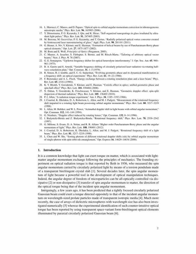
Fig. 1. Illustration of intuitive and counter-intuitive mechanical manifestations of an opticaltorque per photon τz exerted on matter by an incident Gaussian beam carrying (spin) op-tical angular momentum sz per photon along its propagation direction z. (a) Right-handedsituation, szτz > 0 whatever sz. (b) Left-handed situation, szτz < 0 whatever sz.
Noticeably, the angular analog of negative optical forces [6] has been introduced as a ‘left-handed’ effect rather than a ‘negative’ one, hence avoiding potential confusion with the sign ofthe incident angular momentum, which can be positive or negative, irrespective of whether itinduces usual or counter-intuitive mechanical effects. Also, this echoes the fact that physicistsusually refer to a phenomenon as being left-handed to emphasize its counter-intuitive nature.The concept is summarized in Fig. 1 where both right-handed and left-handed manifestationsof the optical torque per photon τz, are illustrated in the case of an incident Gaussian beampropagating along the z axis and carrying a (spin) angular momentum per photon sz. Namelythe former case corresponds to szτz > 0 whereas the latter situation refers to szτz < 0, whateveris the value of sz.
In fact, unconventional manifestations of mechanical effects of light attracted some attentionduring the past few years. In particular, several studies have been devoted to the concept of so-called negative optical forces, namely optical forces that push objects upstream of an incidentphoton flux, see review paper [7], whose first experimental demonstrations have been reportedquite recently [8, 9]. Other examples of non-trivial optomechanics have also been observed,such as optical forces driven by the spin momentum density [10], and predicted, such as trans-verse optical forces and torques [11–14] that are directed perpendicular to the incident photonflux. Regarding the angular momentum of light, it is likely that its transverse and longitudinalcomponents of both spin and orbital nature [15] will bring other optomechanical surprises inthe future.
Here we present complementary experimental analysis with respect to the original reporton optical torque reversal that takes place in the case of space-variant optically anisotropictransparent media [6]. Indeed, in the latter work, the observations consisted in the detection ofrotational Doppler frequency shifts when such spin-orbit optical couplers are rotated aroundthe propagation axis of the incident beam, which is associated to optical torque exerted on thesample. This was done by observing interference pattern obtained from the coherent superposi-tion of the output beam and a non-collinear reference beam. In present study, we report on thetwo-beam (output and reference fields) collinear variant and single-beam (output field alone)option. Both approaches are compared and discussed in the framework of previous dynamicalgeometric phase and rotational Doppler shift experiments based on spin and/or orbital angularmomentum of light.
3
3

a
m = 1/2
d
m = 1
g
m = 3/2
b e h
c f i
x
y
Fig. 2. Design and characterization of azimuthally varying half-wave plate retarders ofazimuthal order m = 1/2 (upper row), 1 (middle row) and 3/2 (bottom row) used in thiswork, with 532 nm operating wavelength. For each m: the left panel shows slow-axis spatialdistribution in the (x,y) plane, where segments refer to the local slow-axis local orientation;the middle panel is the image of the inhomogeneous retarder observed between crossedlinear polarizers whose direction are indicated as white cross in panel (d); the right paneldisplays output intensity profile for circularly polarized incident Gaussian beam, whichcorresponds to an optical vortex beam of topological charge ±2m where the sign dependson the incident polarization state handedness.
2. Spin-orbit optomechanics of space variant birefringent media
2.1. Materials: dielectric q-plates
Following previous work [6], optical torque reversal experiments reported here are performedusing nanostructured glass slabs having a uniform birefringent phase retardation of π (i.e. half-wave plate condition) for the considered wavelength (here 532 nm) and azimuthally varyingoptical axis orientation angle ψ of the form ψ = mφ with m half-integer and φ the usual polarangle in the (x,y) plane, as illustrated in Figs. 2(a)–2(c).
These anisotropic inhomogeneous optical elements, often called ‘q-plates’ in reference tothe work by Marrucci et al. [16], have been fabricated by Altechna R&D using femtosecondlaser writing of self-assembled nanostructures in silica glass. Indeed, subwavelength structur-ing induces form birefringence with in-plane slow/fast axis oriented perpendicular/parallel tothe nanograting wavevector [17]. This is assessed experimentally by observing the samples inbetween crossed linear polarizers, as shown in Figs. 2(d)–2(f).
2.2. Optical consequences of spin-orbit interaction
As detailed in [18], the magnitude of the induced effective optical anisotropy can be preciselycontrolled by adjusting the various writing parameters. By specifying the half-wave plate con-dition, an incident circularly polarized paraxial Gaussian beam carrying (spin) angular mo-mentum per photon σ h (σ = ±1) along the propagation axis z will emerge from the samplewith a total angular momentum that is the sum of a −σ h spin contribution and a 2σmh or-bital contribution [16], which accounts for a complex representation for the electric field ofthe form exp(−iωt + ikz) with ω the angular frequency of light, k the wavevector and time t.
4

In other words, an incident circularly polarized paraxial Gaussian beam is transformed into acontra-circularly polarized optical vortex beam carrying on-axis optical phase singularity withtopological charge 2σm. In fact, this can be easily grasped by evaluating the Jones matrix ofa static q-plate of order m in the circular polarization basis (c+,c−), with cσ = (x+ iσy)/
√2.
Namely, up to an unimportant phase factor,
J(m)static =
(0 e+2imφ
e−2imφ 0
). (1)
Optical vortex generation is therefore described by applying J(m)static on the incident Jones vector
(1,0)T when σ = 1 or (0,1)T when σ =−1, XT being the transpose of X .This is experimentally illustrated in Figs. 2(g)–2(i) where the output doughnut-shaped inten-
sity pattern is shown for m = 1/2, 1 and 3/2. Such optical spin-orbit interaction phenomenonthat couples the spin and orbital angular momentum contributions of light finds its origin in thegeometric phase arising from the spatial rotation of the local coordinate frame attached to theanisotropy axis [19].
2.3. Mechanical consequences of spin-orbit interaction
Besides optical vortex generation from spin-orbit interaction, mechanical effects may also oc-cur. Indeed, angular momentum conservation of the light-matter system implies that an opticalradiation torque τz per photon is exerted on the spin-orbit coupler. More precisely, under inci-dent circularly polarized Gaussian beam with helicity σ , one has
τ(σ)z = τ
(σ)z,spin + τ
(σ)z,orbital , (2)
where the spin and orbital contribution to the total torque are respectively τ(σ)z,spin = 2σ h and
τ(σ)z,orbital =−2σmh, which gives
τ(σ)z = 2σ(1−m)h . (3)
More generally, in the case of an elliptically polarized incident beam characterized by theellipticity angle χ [20] (−π/4 ≤ χ ≤ π/4), which carries hsin2χ spin angular momentumper photon, the optical radiation torque can be found by decomposing the incident field on thecircular polarization basis. One obtains
τ(χ)z =
12
[(1+ sin2χ)τ
(+)z +(1− sin2χ)τ
(−)z
], (4)
henceτ(χ)z = 2sin2χ (1−m)h . (5)
Right-handed optical torque, τ(χ)z sin2χ > 0, is thus obtained for m < 1 whereas left-handed
situation, τ(χ)z sin2χ < 0, occurs for m> 1 when the radiation torque is dominated by the orbital
contribution rather than that of the spin. On the other hand, the particular case m = 1 gives zerotorque, which is a mere consequence of the rotational invariance of the medium around the zaxis. The case of an incident linearly polarized Gaussian beam (χ = 0) also leads to zero nettorque but this results from the exact compensation between the respective contributions of thetwo circular components of the field.
5

2.4. Experimental approach
Optical radiation torque reversal is here addressed by considering two distinct rotationalDoppler shift experiments performed using a continuous-wave laser source operating at 532 nmwavelength. Both experiments, which consist to rotate the sample around the z axis at constantangular frequency Ω, are presented and analyzed in the next section.
The main idea is to probe the opto-mechanical effect of light on the q-plate from the assess-ment of the mechano-optical effect of the rotating q-plate on light, thereby circumventing thepractical difficulty associated with the direct observation of light-induced rotation. Indeed, aspreviously discussed in [6], the fact that a circularly polarized incident beam exerts a nonzerooptical radiation torque (which implies m 6= 1) on the sample is associated with a rotationalDoppler frequency shift δω imparted to the output contra-circularly polarized light field as theq-plate is rotated. The expression of the frequency shift can be derived following energy con-servation principle for the ‘light+matter’ system considered as isolated, namely w+ hδω = 0where w = τzΩ is the work per photon produced on the slab, which gives
δω = 2σΩ(m−1) . (6)
It is also instructive to retrieve Eq. (6) from Jones formalism by evaluating the time-dependentJones matrix that describes the rotating q-plate. First, we note that the optical axis orientationangle ψ , in the fixed reference frame (x,y,z), is rotated by an angle (1−m)ϕ when the sampleis rotated by an angle ϕ around the z axis. The dynamical Jones matrix in the circular polariza-tion basis is thus obtained from Eq. (1) by applying the transformation ψ → ψ +(1−m)Ωt,assuming that the static q-plate starts to rotate with angular velocity Ω at t = 0. This gives
J(m)dynamic =
(0 e+2i[mφ+(1−m)Ωt]
e−2i[mφ+(1−m)Ωt] 0
). (7)
According to the adopted complex representation mentioned above that implies angular fre-quency definition of the form−∂Φ/∂ t, where Φ denotes the phase of the optical field, one thusretrieves from Eq. (7) the expression for the frequency shift given by Eq. (6).
3. Spin-orbit rotational Doppler shift experiments
3.1. Two-beam experiment
In a first set of experiments we have accessed to rotational Doppler shift by using the setupshown in Fig. 3. In practice, the temporal behavior of interferograms obtained using a Mach-Zehnder interferometer is video recorded. Such interferogram consists of the collinear coherentsuperposition of the output light field with a reference Gaussian beam whose circular polariza-tion state is orthogonal to that of the incident Gaussian beam. The q-plate is rotated at constantangular velocity Ω≈ 0.4 rad/s by placing the samples on a motor-controlled rotating stage. Theresults are shown in Fig. 4 for m = (1/2,1,3/2).
For each m, a snapshot of the 2|m|-arm spiraling intensity pattern observed in the (x,y) planeis shown in Figs. 4(a)–(c). The dynamics of the latter pattern is quantitatively retrieved bylooking at the time dependence of the correlation coefficient C between the intensity patterns attime 0 and t, see Figs. 4(d)–(f) that correspond to 120 seconds acquisition time duration. Theobserved time dependence of C(t) as a function of m follows the predicted dependence of thefrequency shift δω given by Eq. (6). Indeed, overall static behavior is found for m = 1, which isbasically associated with the rotational invariance around the z axis of the q-plate. In contrast,when m 6= 1, C(t) exhibits sinusoidal behavior with angular frequency ΩC that satisfies theexpected relationship ΩC = |δω|= 2|(m−1)Ω|. Indeed, data fitting gives ΩC = 0.36 rad/s form = 1/2 and ΩC = 0.40 rad/s for m = 3/2.
6

M
HWP PBS QWP
QWP
NPBS
M
CCDP
QP
Fig. 3. Sketch of the two-beam rotational Doppler experimental set-up used to videorecordthe interference pattern between (i) the frequency shifted output beam emerging from thesample, labeled c(ω+2σΩ(m−1))
−σ , illuminated by collimated circularly polarized Gaussian
beam with waist radius w≈ 1 mm and helicity σ , c(ω)σ , and (ii) a collinear reference beam
with helicity −σ , c(ω)−σ . Optical elements: P is linear polarizer, HWP is half-wave plate,
QWP is quarter-wave plate, QP is q-plate, M is mirror, PBS is polarizing beam splitter,NPBS is non-polarizing beam splitter, CCD is imaging device.
0 40 80 120
0
1
t (s)
C(I
(0),
I(t)
)
m = 1/2. Fitting line 0.45+ 0.51sin(0.36t+0,61)
0 40 80 120
0
1
m = 1
0 40 80 120
0
1
t(s)
C(I
(0),
I(t)
)
m = 3/2 fitting line 0.668+0.3184sin(0.4t+1.19)
a
m = 1/2
d
m = 1
m = 3/2
b e
c f
x
y
g
h
i
T
t
x
y
0 40 80 120
0
1
t(s)
C(I
(0),
I(t)
)
m = 3/2 fitting line 0.668+0.3184sin(0.4t+1.19)
0 40 80 120
0
1
t(s)
C(I
(0),
I(t)
)
m = 3/2 fitting line 0.668+0.3184sin(0.4t+1.19)
t (s)
t (s)
t (s)
C
C
C
0 40 80 120
0
1
t(s)
C(I
(0),
I(t)
)
m = 3/2 fitting line 0.668+0.3184sin(0.4t+1.19)
Fig. 4. Two-beam rotational Doppler experimental results for m = 1/2 (upper row), m = 1(middle row) and m = 3/2 (bottom row) by using the set-up depicted in Fig. 3. For eachm: left panel displays a snapshot of the interference intensity pattern observed in the (x,y)plane at t = 0; middle panel shows the time dependence of the correlation coefficient Cbetween intensity patterns at t = 0 and t where the solid line (for m = 1/2 and 3/2) refersto fit by sinusoidal function, see text for details; right panel is a volumetric representationof the recorded interferogram in the (x,y, t) spatiotemporal frame during T = 120 s.
Remarkably, the reminiscence of optical torque reversal from a right-handed to a left-handedsituation while the input angular momentum is kept fixed as m increases from 1/2 to 3/2 [seethe factor m− 1 in Eq. (5)] is retrieved from the space-time representation of the interfero-grams shown in Figs. 4(g)–(i). Indeed, handedness reversal of the screw-shaped spatiotemporalinterferograms is observed when passing from m = 1/2 [Fig. 4(g)] to m = 3/2 [Fig. 4(i)].
7
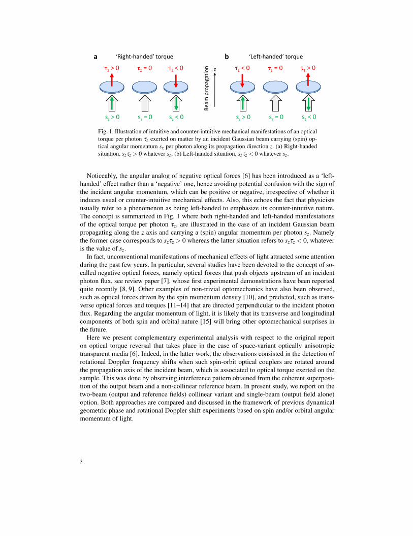
3.2. Single-beam experiment
Following the sketch shown in Fig. 5, reference-free interference pattern can also be obtained byusing a linearly polarized (here along the x axis) incident Gaussian beam instead of a circularlypolarized one. Indeed, the incident field can be described in that case as a coherent superpositionof orthogonally polarized circularly polarized identical Gaussian beams, each of them exertingon the sample an optical radiation torque with equal magnitude and opposite sign. Although thetotal torque exerted on the sample is zero, the individual optomechanical contributions of eachcircularly polarized component of the incident field can nevertheless be retrieved by rotatingthe sample at constant angular frequency Ω.
Practically, this is done by projecting the output field along the y axis by placing a linearpolarizer after the sample, as depicted in Fig. 5. This allows orthogonal circularly polarizedoutput components to interfere and produce a 4|m|-fold rotationally symmetric patterns in the(x,y) plane, as illustrated in the insets of Fig. 6 that correspond to the situation at rest. Moreprecisely, the output field just after the q-plate is described by
E(m,Ω=0)after QP = J(m)
static (1/√
2,1/√
2)T = cos(2mφ)x+ sin(2mφ)y . (8)
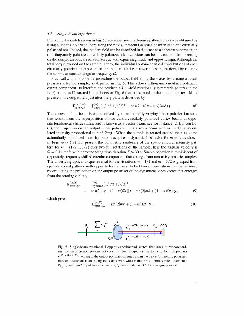
The corresponding beam is characterized by an azimuthally varying linear polarization statethat results from the superposition of two contra-circularly polarized vortex beams of oppo-site topological charges ±2m and is known as a vector beam, see for instance [21]. From Eq.(8), the projection on the output linear polarizer thus gives a beam with azimuthally modu-lated intensity proportional to sin2(2mφ). When the sample is rotated around the z axis, theazimuthally modulated intensity pattern acquires a dynamical behavior for m 6= 1, as shownin Figs. 6(a)–6(c) that present the volumetric rendering of the spatiotemporal intensity pat-tern for m = (1/2,1,3/2) over two full rotations of the sample; here the angular velocity isΩ = 0.44 rad/s with corresponding time duration T ≈ 30 s. Such a behavior is reminiscent ofoppositely frequency shifted circular components that emerge from non-axisymmetric samples.The underlying optical torque reversal for the situations m = 1/2 and m = 3/2 is grasped fromspatiotemporal patterns with opposite handedness. In fact these observations can be retrievedby evaluating the projection on the output polarizer of the dynamical Jones vector that emergesfrom the rotating q-plate,
E(m,Ω)after QP = J(m)
dynamic (1/√
2,1/√
2)T ,
= cos(2[mφ +(1−m)Ωt)]x+ sin(2[mφ +(1−m)Ωt)]y , (9)
which givesE(m,Ω)
after Pout= sin(2[mφ +(1−m)Ωt)]y . (10)
CCDPin Pout
QP
Fig. 5. Single-beam rotational Doppler experimental sketch that aims at videorecord-ing the interference pattern between the two frequency shifted circular componentsc(ω+2σΩ(1−m))
σ , owing to the output polarizer oriented along the y axis for linearly polarizedincident Gaussian beam along the x axis with waist radius w ≈ 1 mm. Optical elements:Pin/out are input/output linear polarizers, QP is q-plate, and CCD is imaging device.
8

x
y
a m = 1/2 b m = 1 c m = 3/2
t x
y
TEx
per
imen
t
d m = 1/2 e m = 1 f m = 3/2
Mo
del
Fig. 6. Single-beam rotational Doppler experiment for m = 1/2 (left column), m = 1 (mid-dle column) and m = 3/2 (right column) following the set-up shown in Fig. 5. Snapshotof the intensity profile in the (x,y) plane of the linearly polarized output component that isorthogonal to that of a linearly polarized incident Gaussian beam is shown in the inset ofeach panel whereas the spatiotemporal behavior are represented with volumetric renderingover a duration that corresponds to two full rotations of the sample, T ≈ 30 s. Upper row:experiment. Bottom row: model.
The resulting intensity pattern thus has angular frequency [(m− 1)/m]Ω, which matches withthe observed time-periodic behavior in Figs. 6(a)–6(c). Assuming a radial dependence of theoutput beam of the form of a paraxial Laguerre-Gaussian beam with azimuthal index l = 2m andradial index p = 0 (which formally neglects the radial modal content of the field generated bythe q-plate, but does not affect qualitatively the predictions) the corresponding spatiotemporalintensity pattern is described as
I(r, t) = (r/w)4|m| exp(−2r2/w2)sin2(2[mφ +(1−m)Ωt]) , (11)
where w is the beam waist radius, see Figs. 6(d)–6(f) and a fair agreement with experimentaldata is obtained.
4. Discussion and conclusion
Early rotational Doppler frequency shift experiments were performed with uniform uniaxialoptical retarders, namely rotating half-wave plates [22, 23] where the frequency shift impartedto light has been treated using Jones formalism. Later, variants have been also reported, forinstance using a rotating quarter-wave plate, albeit described from the point of view of the geo-metric phase [24]. Still, in [24], Simon et al. have emphasized the equivalence of the rotationalDoppler effect and geometric phase in systems with rotating elements. Such an equivalencehas been rediscussed later in the framework of energy conservation considerations in [25] byBretenaker and Le Floch, who also provided identical conclusions supported by experimentalobservations. Rotational Doppler shift experiments have also been extended to the case of or-bital angular momentum [29], which has provided experimental foundations to earlier theoreti-cal predictions [30–32]. On the other hand, present work should also be replaced in the context
9

of vector beams since they are involved in the single-beam experiment. Indeed, when rotated,a vector beam acquires a geometric phase that is related to its rotational symmetry [33]. Sincein our case the generated vector beam is put into rotation, see Eq. (9), the measured rotationalfrequency shift manifests as a dynamical geometric phase for vector beams.
From a general point of view, the equivalence mentioned above is not restricted to propagat-ing fields and also holds for surface waves as reported for instance by Bliokh et al. in [26] inthe case of visible domain radiation (λ ∼ 0.5 µm) and by Dahan et al. in [27] in the case ofthermal radiation (λ ∼ 10 µm).
Noticeably, the connection between optical radiation torque driven by the spin angular mo-mentum of light and rotation-induced frequency shift has been discussed a long time beforeabove mentioned works, in the case of a microwave experiment [28].
In such context, present experiments carried out with space-variant optically anisotropicstructures, which are basically spin-orbit scattering transparent optical elements, constitute anoptomechanical spin-orbit approach to the long-lasting topic of optical rotational Doppler fre-quency shifts, dynamical geometric phase and angular momentum of light. In particular wemention the unified picture in terms of the Coriolis effect reported in [26] and that is associatedto observations in a noninertial reference frame, noting that in our case it is the medium thatrotates instead of the observer; in turn one passes from one situation to another by mere changeof sign of the involved angular velocity.
We also note that the spin-orbit version proposed here shares some analogy with previous ex-perimental work regarding the additive contribution of the spin and orbital angular momentumcomponents of light to the frequency shift [34]. Moreover, our results bring an an experimentalplayground to previous theoretical study that discussed the use of spin-orbit rotational Dopplerfrequency shifts for encoding an extra degree of freedom into a light field [35]. Finally, as faras optomechanics itself is concerned, we stress that the direct experimental observation of aleft-handed optical radiation torque is still an open issue at present day on which we shouldhopefully report in a near future.
Acknowledgment
This study has been carried out with financial support from the French State, managed bythe French National Research Agency (ANR) in the frame of “the Investments for the future”Programme IdEx Bordeaux – LAPHIA (ANR-10-IDEX-03-02).
10